1
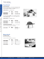
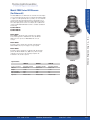
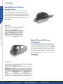
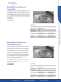
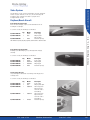
Strobe
StrobeLighting
Lighting
Avionics & Accessories
Stobe Systems
The following are strobe system recommendations. The basic model/part
numbers are given. However, in some cases, the aircraft voltage and
mounting location of the light are needed to specify the exact
model/part number needed.
Raytheon/Beech Aircraft
Early model twin engine-1966
Due to the slanted wing-tip, require custom fabricated brackets for
mounting the strobe lights.
To convert to strobes, the following is recommended:
P/N 01-0770028-05
P/N 01-0770058-03
Qty.
Model
1
2
HDACF
A625
Description
Whelen Engineering Co., Inc.
Power supply
Wing-tip strobe
light assembly
P/N 01-0750206-00
1
HD60
Installation package
REF: All Barons (95-55, A55, B55, C55, D55) & all Travel Airs. 1957 thru 1969
Early model single engine-1966
Excluding any modified wing-tip, use position lights at the wing-tip
extremity.
To convert to strobes, the following is recommended:
Qty.
P/N 01-0770028-05
P/N 01-0770054-00
P/N 01-0770054-02
P/N 01-0750206-00
1
1
1
1
Model
Description
HDACF
A650PG14
A650PR14
HD60
Power supply
Wing-tip light
Wing-tip light
Installation package
Single engine 1967-1973
Use position lights installed under clear fairings at the wing-tips most
forward position.
To convert to strobes, the following is recommended:
Model
Description
P/N 01-0770028-05
P/N 01-0770058-03
P/N 01-0770024-00
Qty.
1
2
1
HDACF
A625
A500AV14
P/N 01-0770024-01
1
A500AV28
P/N 01-0750205-00
1
HDT390
Power supply
Wing-tip strobe light
Tail strobe/position
light (lens may be
removed to reduce
heat build-up)
Tail strobe/position
light (lens may be
removed to reduce
heat build-up)
Installation package
214.320.9770
D a l l a s Av i o n i c s
800.527.2581
263
Strobe
StrobeLighting
Lighting
Avionics & Accessories
Raytheon/Beech Aircraft
Whelen Engineering Co., Inc.
Baron, Rudder Mount Oscillating Beacon replacement
Single engine 1974 and Later
Use a commonality wing-tip, that enlarged the clear fairing by
approximately six inches.
To convert to Whelen strobes the following is recommended:
Qty.
P/N 01-0770028-05
P/N 01-0790028-03
P/N 01-0770024-00
P/N 01-0770024-01
P/N 01-0750205-00
1
2
1
1
1
Model
Description
HDACF
D900283
A500AV14
A500AV28
HDT390
Power supply
Wing-tip strobe light
Tail strobe/position light
Tail strobe/position light
Installation package
To convert the existing Rudder Mount Oscillating Beacon to a solid state
Halogen Flasher, the following is recommended:
P/N 01-0790044-57
Qty.
Model
Description
1
9004457
Flashing anti-collision
light assembly (red)
The Oscillating Beacon first appeared in 1970 on the then new E55, until
1982. All Model 58’s used it from 1970 thru 2000.
Duke, Oscillating Beacon replacement
To convert the existing Oscillating Beacon to a solid state Halogen Flasher,
the following is recommended:
264
Qty.
Model
Description
P/N 01-0790044-01
1
9004401
P/N 01-0790044-17
1
9004417
Flashing anti-collision
light assembly (red),
5-hole mount
Flashing anti-collision
light assembly (red),
8-hole mount
214.320.9770
D a l l a s Av i o n i c s
800.527.2581
Strobe
StrobeLighting
Lighting
Avionics & Accessories
Raytheon/Beech Aircraft
Rotating Beacon Replacement
Qty.
Model
Description
P/N 01-0770029-29
1
HRCFAR
P/N 01-0770029-30
1
HRCFAW
P/N 01-0770029-31
1
HRCFAS
P/N 19-130074-009
1
A440
Standard assembly,
red lens
Standard assembly,
white lens
Standard assembly,
split red/white lens
Mounting adapter
(required for new
fuselage mounting)
Whelen Engineering Co., Inc.
To convert the existing Rotating Beacon to a strobe, the following
is recommended:
Round rotating beacon was used on the vertical fin of all Barons from
1961-1969. Models using this light are 95-55 (1961), A55 (1962-63), B55
(1964-1982), C55 (1966-1967), D55 (1968-1969).
Note: The B55 Baron continued to use this beacon until production
stopped in 1982.
Cessna Aircraft
Note: Whelen does not have specific kits set up. However, the following
are strobe system recommendations.
Wing-tip strobes for early model single engine through 1961
Excluding any modified wing-tip, use position lights at the
wing-tip extremity.
To convert to strobes, the following is recommended:
Qty.
P/N 01-0770028-05
P/N 01-0770054-00
P/N 01-0770054-02
P/N 01-0750206-00
1
1
1
1
Model
Description
HDACF
A650PG14
A650PR14
HD60
Power supply
Wing-tip light
Wing-tip light
Installation package
Wing-tip strobes for single engine 1962-1969
Requires modification to the factory wing-tip to accommodate the
light assemblies.
To convert to strobes, the following is recommended:
Qty.
P/N 01-0770028-05
P/N 01-0770054-00
P/N 01-0770054-02
P/N 01-0750206-00
1
1
1
1
Model
Description
HDACF
A650PG14
A650PR14
HD60
Power supply
Wing-tip light
Wing-tip light
Installation package
214.320.9770
D a l l a s Av i o n i c s
800.527.2581
265
Strobe
StrobeLighting
Lighting
Avionics & Accessories
Cessna Aircraft
Wing-tip strobes for single engine 1972
Later excluding any modified wing-tip, spare wires were installed at the
factory from a switch position on the instrument panel to the farthest rib
in each wing-tip. This allows mounting of the power supplies adjacent
to the strobe light, which reduces installation time significantly. Wing-tip
strobes were also an option in the early 70’s. We estimate that 40%-50%
had factory installed systems.
Replacement parts for aircraft with factory installed systems:
Model
Description
P/N 01-0770006-09
Qty.
2
A490TCCF
P/N 02-0250274-00
P/N 68-4290001-30
2
2
A427
A428
Wing-tip strobe
power supply
Wing-tip strobe tube
Wing-tip strobe lens
Whelen Engineering Co., Inc.
Recommended parts for aircraft without factory installed systems:
Model
Description
P/N 01-0770006-09
Qty.
2
A490TCCF
P/N 02-0250276-00
2
A610
P/N 68-2290005-30
P/N 01-0750216-00
2
1
A612
HT
Wing-tip strobe
power supply
Wing-tip strobe
tube assembly
Wing-tip strobe lens
Installation package
Note: A small percentage of 1972 and later aircraft used the
1962-1969 wing-tip.
Rotating Beacon replacement for early model single engine
through 1966
The first form of anti-collision light for aircraft was a rotating beacon.
These beacons were installed from the late 50’s through 1966.
To convert the rotating beacon to a strobe, the following is recommended:
266
Qty.
Model
Description
P/N 01-0770029-29
1
HRCFAR
P/N 01-0770029-30
1
HRCFAW
P/N 01-0770029-31
P/N 19-130074-009
1
1
HRCFAS
A440
Standard assembly,
red lens
Standard assembly,
white lens
Standard assembly, split
Red/white lens
mounting adapter
(required fuselage
mounting)
214.320.9770
D a l l a s Av i o n i c s
800.527.2581
Strobe
StrobeLighting
Lighting
Avionics & Accessories
Cessna Aircraft
Quartz Halogen Flasher replacement for single engine vertical
fin, 1967 and later
In 1967 Cessna changed from a Rotating Beacon to a Quartz Halogen
Flasher Beacon. This has a 150-watt 28V quartz halogen lamp, or
a 125-watt 14V quartz halogen lamp, operated from a solid state
electronic module.
Qty.
Model
Description
P/N 01-0770019-18
1
A470AR
P/N 01-0770019-19
1
A470AW
P/N 01-0770019-20
1
A470AS
P/N 01-0770062-03
1
A490ATSC
P/N 01-730068-000
P/N 01-0750218-00
1
1
H102
HT10
Strobe light
assembly, red
Strobe light
assembly, white
Strobe light
assembly, split
red/white
Power supply
assembly
Mounting adapter
Installation package
Whelen Engineering Co., Inc.
To convert to a strobe, the following is recommended:
Cessna 300A, B, C & D Twin Engines
The system for these airplanes requires fabricated brackets for affixing
the power supplies, and for attaching the strobe to a new position light
bracket.
To convert to strobes, the following is recommended:
Qty.
Model
Description
P/N 01-0770006-08
P/N 01-0770058-03
P/N 01-0770024-01
3
2
1
A490TCF
A625
A500AV
P/N 01-0750216-00
1
HT
Power supply
Wing-tip strobe light
Tail strobe/position
light
Installation package
The remaining Cessna 300-400 Series Twin Engines
The system for these airplanes requires the same hardware as
above, however, they had factory installed Grimes assemblies from
approximately 1969 and later. To replace the existing system, all
parts must be replaced and some wiring must be changed along
with custom fabricated brackets.
Rotating Beacon replacement.
To convert the existing rotating beacon to a strobe, the following is
recommended:
Qty.
Model
Description
P/N 01-0770029-29
1
HRCFAR
P/N 01-0770029-30
1
HRCFAW
P/N 01-0770029-31
1
HRCFAS
P/N 19-130074-009
1
A440
Standard assembly,
red lens
Standard assembly,
white lens
Standard assembly,
split red/white lens
Mounting adapter
(required for new
fuselage mounting)
214.320.9770
D a l l a s Av i o n i c s
800.527.2581
267
Strobe
StrobeLighting
Lighting
Avionics & Accessories
Cessna Aircraft
Cessna Citation Series
Whelen has an STC’d system to convert factory installed Grimes wing-tip
strobes. The initial STC ST22BO was for Citation 550, S550 & 560, serial
number 128 thru 256. The following is recommended:
P/N 01-0716164-03—STC (# ST22BO) includes:
Qty.
Model
Description
2
1
1
9010104
9015905
9015906
Power supply
Strobe light assembly
Strobe light assembly
P/N 01-0790101-04
P/N 01-0790159-05
P/N 01-0790159-06
The second system, STC ST0010BO covers serial number 257 and later,
and any aircraft that installed Cessna service bulletin SB560-33-08 from
serial number 0001 thru 0256.
Whelen Engineering Co., Inc.
P/N 01-0716164-05—STC (#ST0010BO) includes:
Qty.
Model
Description
2
1
1
9010104
9020603
9020604
Power supply
Strobe light assembly
Strobe light assembly
P/N 01-0790101-04
P/N 01-0790206-03
P/N 01-0790206-04
Oscillating Beacon replacement
To convert the existing rudder mount oscillating beacon to a solid state
quartz halogen flasher, the following is recommended:
Qty.
Model
Description
1
9004433
Flashing anti-collision
light assembly
P/N 01-0790044-33
Mooney Aircraft
Early Model Flat Wing
Exterior position light mounting.
To convert to strobes, the following is recommended:
Qty.
268
Model
Description
P/N 01-0770028-05
P/N 01-0770054-00
1
1
HDACF
A650PG14
P/N 01-0770054-02
1
A650PR14
P/N 01-0750206-00
1
HD60
Power supply
Wing-tip strobe/position
light
Wing-tip strobe/position
light
Installation package
214.320.9770
D a l l a s Av i o n i c s
800.527.2581
Strobe
StrobeLighting
Lighting
Avionics & Accessories
Mooney Aircraft
Enclosed Wing-tip (New Installation)
Model
Description
P/N 01-0770028-05
P/N 01-0770054-00
Qty.
1
1
HDACF
A650PG14
P/N 01-0770054-02
1
A650PR14
P/N 01-0770024-00
1
A500AV14
P/N 01-0770024-01
1
A500AV28
P/N 01-0750205-00
1
HDT390
Power supply
Wing-tip strobe/
position light
Wing-tip strobe/
position light
Tail strobe/position
light assembly, 14V
Tail strobe/position
light assembly, 28V
Installation package
Whelen Engineering Co., Inc.
To convert to strobes, the following is recommended:
Enclosed Wing-tip (Hoskins/SDI Replacement)
Slight modification required to convert to strobes, the following
is recommended:
Qty.
Model
Description
P/N 01-0770028-05
P/N 01-0770058-03
3
2
A490TCF
A625
P/N 01-0750216-00
P/N 01-0770024-00
1
1
HT
A500AV14
P/N 01-0770024-01
1
A500AV28
Power supply
Wing-tip strobe
light assembly
Installation package
Tail strobe/position
light assembly, 14V
Tail strobe/position
light assembly, 28V
Rotating Beacon Replacement
To convert the existing rotating beacon to a strobe, the following
is recommended:
Qty.
Model
Description
P/N 01-0770029-29
1
HRCFAR
P/N 01-0770029-30
1
HRCFAW
P/N 01-0770029-31
1
HRCFAS
P/N 19-130074-009
1
A440
Standard assembly,
red lens
Standard assembly,
white lens
Standard assembly,
split red/white lens
Mounting adapter
(required for new
fuselage mounting)
214.320.9770
D a l l a s Av i o n i c s
800.527.2581
269
Strobe
StrobeLighting
Lighting
Avionics & Accessories
Piper Aircraft
Single Engines and Piper Aztec
The same wing-tip strobe system can be used on most Piper
aircraft models.
To convert to strobes, the following is recommended:
Model
Description
P/N 01-0770028-05
P/N 01-0770054-00
Qty.
1
1
HDACF
A650PG14
P/N 01-0770054-02
1
A650PR14
P/N 01-0750206-00
1
HD60
Power supply
Wing-tip strobe/position
light 14V
Wing-tip strobe/position
light 14V
Installation package
Whelen Engineering Co., Inc.
Piper Navajo
System is as follows:
Model
Description
P/N 01-0770028-05
P/N 01-0770054-01
Qty.
1
1
HDACF
A650PG28
P/N 01-0770054-03
1
A650PR28
P/N 01-0770024-03
1
A500AH28
P/N 01-0750205-00
1
HDT390
Power supply
Wing-tip strobe/position
light, 28V
Wing-tip strobe/position
light, 28V
Tail position/strobe light
assembly, 28V
Installation package
Piper Cheyenne I, II, & IIXL
Factory equipped with Whelen strobes.
Rotating Beacon Replacement
To convert the existing rotating beacon to a strobe, the following
is recommended:
270
Qty.
Model
Description
P/N 01-0770029-29
1
HRCFAR
P/N 01-0770029-30
P/N 01-0770029-31
1
1
HRCFAW
HRCFAS
P/N 19-130074-009
1
A440
Standard assembly,
red lens
Standard, white lens
Standard assembly,
split red/white lens
Mounting adapter
(required for new
fuselage mounting)
214.320.9770
D a l l a s Av i o n i c s
800.527.2581
Strobe
StrobeLighting
Lighting
Aircraft with Standard Wing-tips
This is the most widely used system on the market. It provides all
of the necessary components for anti-collision and position lights,
without the need for a remote taillight. The power supply is mounted
in the fuselage, and the shielded cable is run to the lights.
The following is recommended:
Model
Description
P/N 01-0770028-05
P/N 01-0790006-00
Qty.
1
1
HDACF
A600PG14
P/N 01-0790006-02
1
A600PR14
P/N 01-0750206-00
1
HD60
Power supply
Wing-tip strobe/
position/tail
light, 14V
Wing-tip strobe/
position/tail
light, 14V
Installation package
Aircraft with Enclosed Wing-tip Fairings
If the position and strobe lights are to be mounted under a clear
fairing, the need for a third tail strobe is required.
To convert to strobes, the following is recommended:
Qty.
Model
Description
Power supply
Wing-tip strobe/
position light, 14V
Wing-tip strobe/
position light, 14V
Tail position/strobe
light assembly
Installation package
P/N 01-0770028-05
P/N 01-0770054-00
1
1
HDACF
A650PG14
P/N 01-0770054-02
1
A650PR14
P/N 01-0770024-00
1
A500AV14
P/N 01-0750205-00
1
HDT390
Aircraft with Wing-tip Mounted Power Supplies
If the builder chooses to mount the strobe power supplies in the wings,
adjacent to the light head assemblies the following is recommended:
Model
Description
P/N 01-0770062-03
P/N 01-0790006-00
Qty.
2
1
A490ATSC
A600PG14
P/N 01-0790006-02
1
A600PR14
P/N 01-0750215-00
2
HS5
Power supply
Wing-tip strobe/
position/tail
light, 14V
Wing-tip strobe/
position/tail
light, 14V
Installation package
214.320.9770
Aircraft with Enclosed Wing-tip Fairings and Wing-tip
Mounted Power Supplies
If the position and strobe lights are to be mounted under a clear
fairing, the need for a third tail strobe is required.
The following is recommended:
Model
Description
P/N 01-0770062-03
P/N 01-0770054-00
Qty.
2
1
A490ATSC
A650PG14
P/N 01-0770054-02
1
A650PR14
P/N 01-0770024-00
1
A500AV14
P/N 01-0750215-00
3
HS5
Power supply
Wing-tip strobe/
position/tail
light, 14V
Wing-tip strobe/
position/tail
light, 14V
Tail position/strobe
light assembly, 14V
Installation package
D a l l a s Av i o n i c s
800.527.2581
Whelen Engineering Co., Inc.
Avionics & Accessories
Homebuilts & Kit Aircrafts
271
Light
LightRequirements,
Requirements,Locations
Locations&&Distribution
Distribution
Avionics & Accessories
Anti-Collision & Position Light
Requirements, Locations, &
Distribution Patterns
Installation Locations
Wing-tip
All aircraft must have an approved anti-collision light and position light
system for nighttime operations. The position lights consist of an Aviation
Red on the left side, an Aviation Green on the right, and an Aviation White
taillight (REF. FAR 23.1389). The position lights must be wired independent
of the anti-collision lights.
The anti-collision lighting system is required under FAR PART 91.205(c).
There are different requirements affecting different aircraft. These
aircraft are categorized by the date of application or certificate type.
Home built aircraft are determined by the date of issuance of the
Experimental Operating Limitations. The different categories are
as follows:
Whelen Engineering Co., Inc.
• Aircraft for which type certificate was applied for after
April 1, 1957 to August 10, 1971:
These anti-collision systems must produce a minimum of 100
effective candela in aviation Red or White (REF. FAR 23.1397), 360˚
around the aircraft's vertical axis, 30˚ above and below the horizontal
plane (REF. FAR 23.1401).
• Aircraft for which type certificate was applied for after
August 11, 1971 to July 18, 1977:
These anti-collision systems must produce a minimum of 400
effective candela in aviation Red or White (REF. FAR 23.1397), 360˚
around the aircraft's vertical axis, 30˚ above and below the horizontal
plane (REF. FAR 23.1401).
• Aircraft for which type certificate was applied for after
July 18, 1977:
These anti-collision systems must produce a minimum of 400
effective candela in aviation Red or White (REF. FAR 23.1397), 360˚
around the aircraft's vertical axis, 75˚ above and below the horizontal
plane (REF. FAR 23.1401).
Radio Noise Suppression
Whelen strobe light lenses P/N A428, A457A, A612 and the A402A
are available with an advanced RF shielding technique that Whelen
engineering developed to reduce radio interference. When properly
grounded to the aircraft structure, these radio shielded strobe light
heads will reduce the radiated RF energy created by the trigger pulse
as much as 15-17 DB. (To locate RF shielded parts, refer to Whelen
Engineering’s strobe light parts list). A429 strobe light head, use the
A428-D which is an RF shielded A428 lens epoxied into an A426 retainer.
A470A, can be radio shielded by replacing the existing lens with
P/N A402A-D( ) color. A500A, use the A457B-D, V or H which is an
RF shielded A457A lens epoxied into an A425A-V or H lens retainer.
A650 strobe light head, use the A626-D which is an RF shielded A612
lens epoxied into an A626 lens retainer.
The installation time for wing-tip strobe light systems will vary depending
on the type of system being installed. Installation time can be greatly
reduced if it is done in conjunction with an annual or 100-hour inspection.
The major difference in the systems is the location of the strobe power
supply. They can be mounted locally, one in each wing-tip, or a single
power supply mounted in the fuselage.
There has been some concern in the past with running the high voltage
cable through the wings and by the fuel tanks. For there to be an explosion
two conditions must be met. There must be an explosive atmosphere,
and there must be a source of ignition. For there to be an explosive
atmosphere inside the wing, it would require a fuel tank leaking into the
wing. However, strobe power cables are not routed through the wing
bays, they are routed forward or aft. Then there is the matter of spark
for ignition. For this to occur there would have to be a breakdown of
the cable insulation. This is very unlikely if the cable has been properly
installed. The power supplies are designed to turn off when there is a
short. With power supplies mounted in the wing, the input wires still
need to be run to provide power to them.
Fuselage
Another option is to install fuselage mounted units. They can be either
self contained, in which the power supply and light head are one unit, or
remote light heads run off a separate power supply. To meet the field of
coverage, one must be on the top of the fuselage and one on the bottom.
Vertical Fin
Lastly if applicable, a single anti-collision light can be mounted on the
vertical stabilizer. It also can be either a self contained unit or a remote
light head, depending on the aircraft.
How to Choose A Power Supply
The power supply needed depends on the application, and the mounting
location. The model HDA,CF series is a fuselage mounted power supply
that will power two or three lights. The model HTS,CF series is designed
for installation adjacent to the strobe light head and will power one light
assembly. The model HT,CF series is the most economical power supply
when adding only one light. It mounts adjacent to the strobe light head
assembly. (Not legal for light output with red strobe light) Most other
Whelen power supplies are application specific, contact factory for
details. Unless otherwise noted, all power supplies are CometFlash®.
About CometFlash®
Whelen engineering is proud to have introduced the CometFlash CF, a
major advancement in the field of safety lighting. By pulsing the flash
tube four times in rapid succession, the effective “on-time” of the strobe
is increased from 2/1000 of a second to 4/10 of a second. This increases
your airplane’s visibility. The development of the CometFlash® reflects
Whelen’s dedication to safety.
272
214.320.9770
D a l l a s Av i o n i c s
800.527.2581
Position
PositionLight
LightAssemblies
Assemblies
Avionics & Accessories
Model 70905 Series LED Beacons
(For Rotorcraft)
The Model 70905 Series are FAA TSO’d self-contained anti-collision lights
for rotorcraft. An external power unit is not required. The durability of LED’s
as a light source will significantly reduce operating costs associated with
spare part replacement and premature failure of existing light sources.
All units meet the minimum requirements stated in FAR Parts 27 & 29 for
anti-collision light systems used on rotorcraft, Ref; Class I (150 effective
candela) of SAE AS8017a Minimum Performance standards. (Available in
28 volts only).
P/N 01-0770905-01
P/N 01-0770905-02
P/N 01-0770905-03
Model 7090501 is designed to replace existing beacons with the
5 hole-mounting pattern on a 4.656 Dia. bolt circle. (Ref. Whelen
70285 series). It incorporates an MS3102R10SL-3P connector
for input.
70905-01
Model 7090502
Designed to replace existing remote mounted strobe lights (Ref.
Whelen A470A series). A power supply is no longer required.
Model 7090503
Designed to replace existing beacons with the 3-3/4” Dia. mounting
pattern. (Ref. Whelen HRCFA series, 90081 Series, and the old style
rotating beacons). It has the same mounting hole pattern. No
modification to the aircraft is required.
70905-02
Specifications
Power Consumption
LED Color
Weight
Exposed Height
Exposed Diameter
Approvals
70905-01
70905-02
70905-03
0.45 AMPS @ 28VDC
Aviation red
1.4 lbs.
4.04”
3.66”
FAA/TSO-C96a
0.45 AMPS @ 28VDC
Aviation red
1.2 lbs.
4.14”
3.66”
FAA/TSO-C96a
0.45 AMPS @ 28VDC
Aviation red
1.1 lbs.
3.1”
2.8”
FAA/TSO-C96a
Whelen Engineering Co., Inc.
Model 7090501
70905-03
214.320.9770
D a l l a s Av i o n i c s
800.527.2581
273
LED
LEDLighting
Lighting
Avionics & Accessories
Model 90088 Series LED Ground
Recognition Light
The Model 90088 Series is a ground recognition light assembly. The
solid-state circuitry obsoletes the “old style” oscillating mechanical
beacon, (no moving parts). There is no EMI or RFI produced. Reduced
current draw results in no inrush current spikes to show up on your strike
finder. Crisp on off cycles compared to flashing and mechanical beacons.
All units comply with the color requirements stated in FAR Parts 23, and
25 for Aviation Red. They are compatible with existing ground recognition
light mounting patterns and profiles without altering the aircraft.
P/N 01-0790088-( )
Whelen Engineering Co., Inc.
Specifications
Power Consumption
LED Color
Weight
Exposed Height
Length
Description
Approvals
0.45 AMPS @ 28VDC
Aviation red
1.8 lbs. (nominal)
2.70”
9.87”
Ground recognition light
FAA design conformity
RTCA/DO-160d
Model 70875 Series LED Forward
Position Lights
The Model 70875 Series, are fully FAA TSO’d forward position lights.
They result in a high quality, long lasting, modern alternative to existing
incandescent and halogen forward position lights. The solid state LED
light source has shown conservative lab life results greater than 20,000
hours. They are Shock & Vibration resistant due to no fragile filament to
break or burn out. The lens design is hard-coated polycarbonate. These
advantages will greatly reduce operating costs. All units comply with
the color requirements stated in FAR Parts 23, 25, 27 and 29 for Aviation
Red, and Aviation Green. They are compatible with existing position light
mounting patterns and profiles.
P/N 01-0770875-01
P/N 01-0770875-02
Specifications
Power Consumption
Weight:
Exposed Height
Exposed Diameter
0.35 AMPS @ 28VDC
0.26 lbs.
1.39”
3.92”
Model 7087501
LED Color
Description
Approvals
274
Aviation red
Green position light 28V
FAA/TSO-C30c Type II
214.320.9770
Model 7087502
Aviation green
Red position light 28V
FAA/TSO-C30c Type I
D a l l a s Av i o n i c s
800.527.2581
LED
LEDLighting
Lighting
The Model 90285 series are forward position light modules for enclosed
wing-tips. They are designed to eliminate the need for dual mounted
position lights typical with most corporate and commuter aircraft. They
have all the advantages associated with using LED’s as a light source
to improve reliability and reduce operating costs. All units comply with
the color requirements stated in FAR Parts 23, 25, 27 and 29 for Aviation
Red and Aviation Green. Contact factory regarding custom designs for
specific aircraft.
P/N 01-0790285-01
P/N 01-0790285-02
Specifications
Power Consumption
Weight
Exposed Height
Exposed Diameter
LED Color
Description
Approvals
0.6 AMPS @ 28VDC
0.55 lbs.
1.52”
4.78”
Model 9028501
Model 9028502
Aviation red
Green position light 28V
FAA/TSO-C30c Type II
Aviation green
Red position light 28V
FAA/TSO-C30c Type I
Model 70900 Series LED Beacons
(For Fixed Wing Aircraft)
Whelen Engineering Co., Inc.
Avionics & Accessories
Model 90285 Series LED Forward
Position Lights
The Model 70900 Series are FAA TSO’d self-contained anti-collision
lights for fixed wing aircraft. An external power unit is not required.
The durability of LED’s as a light source will result in a high quality,
long lasting modern alternative to existing anti-collision lighting. The
solid state LED light source has shown conservative lab life results
greater than 20,000 hours. There is no EMI or RFI produced. The lens
design is one-piece construction that is much less susceptible to
environmental or chemical breakdown. Low current draw means no
inrush current that is inherent with strobes and halogen flashers. All
units meet the minimum requirements stated in FAR Parts 23 & 25 for
anti-collision light systems used on fixed wing aircraft, Ref; Class III
(100 effective candela) of SAI AS8017a Minimum Performance
standards. (Specify voltage when ordering).
Models 7090002 & 7090003, are designed to replace existing remote
mounted strobe lights (Ref. Whelen A4704A series). A strobe power
supply is no longer required.
P/N 01-0770900-02
P/N 01-0770900-03
Specifications
LED Color
Weight
Exposed Height
Exposed Diameter
Power Consumption
Description
Approvals
214.320.9770
D a l l a s Av i o n i c s
Aviation red
1.1 lbs.
4.14”
3.66”
Model 709002
Model 709003
0.85 AMPS @ 14VDC
Red LED beacon, 14V
FAA/TSO-C96a
0.425 AMPS @ 28VDC
Red LED Beacon, 28V
FAA/TSO-C96a
800.527.2581
275
Position
PositionLight
LightAssembly
Assembly
Avionics & Accessories
Whelen Engineering Co., Inc.
276
Models 7090004 & 7090005
Designed to replace existing light assemblies with the 3-3/4” Dia.
mounting pattern. (Ref. Whelen HRCFA series, 90081 Series, and the
“old style” rotating beacons). It has the same mounting hole pattern.
No modification to the aircraft is required.
P/N 01-0770900-04
P/N 01-0770900-05
Specifications
LED Color
Weight
Exposed Height
Exposed Diameter
Power Consumption
Description
Approvals
Aviation red
1.1 lbs.
3.1”
2.8”
Model 7090004
Model 7090005
0.85 AMPS @ 14VDC
Red, 3-3/4 dia mount, 1V
FAA/TSO-C96a
0.425 AMPS @ 28VDC
Red, 3-3/4 dia mount, 28V
FAA/TSO-C96a
214.320.9770
D a l l a s Av i o n i c s
800.527.2581
The model 70844 series are LED instrument post light assemblies.
They are designed to illuminate the instrument panel, and function
as instrument mounting bolts. It is a high quality, long lasting, modern
alternative to standard incandescent post lights. They offer significant
technological upgrades over existing products. Utilizing LED technology,
the following advantages are offered. Long life—approximately
20,000 hours.
A reduced power consumption—compared to alternative light
sources. Shock and vibration resistant—no fragile filament to burn
out. Light—produces bright white light. No EMI or RFI interference.
P/N 01-0770844-00
P/N 01-0770844-01
P/N 01-0770844-02
P/N 01-0770844-03
Specifications
Weight
Exposed Height
Power Consumption
Drawing Number
0.03 lbs.
1.00" w/o spacer, 1.12" w/spacer
0.02 AMPS @ 14V, & 0.02 AMPS @ 28V
70844
Model
Description
Approvals
7084400
7084401
7084402
7084403
14V, 1.00" post
14V, 1.50" post
28V, 1.00" post
28V, 1.50" post
—
—
—
—
A350 & A350CN Series
FAA/PMA Approved
Instrument post light assemblies designed to illuminate the instrument
panel and function as instrument mounting bolts. The A350 is identical to
the A350CN, but without the connector nut.
P/N 01-0770116-( )
P/N 01-0770119-( )
Whelen Engineering Co., Inc.
70844 Series
Avionics & Accessories
Interior
InteriorLighting
Lighting
Specifications
Weight
Exposed Height
Power Consumption
Drawing Number A350
Drawing Number A350CN
0.037 lbs.
875” w/o spacer, 1.00” w/spacer
0.2 AMPS @ 6V, 0.08 AMPS @ 14V, & 0.04 AMPS @ 28V
70116
0119
Model Number
Description
A350
A350CN
Instrument post light assemblies
Instrument post light assemblies
Ordering Options
Lens Colors
Post Colors
Post Heights
Voltages
IW = Instrument white
CL = Clear
RD = Red
BK = Black
GR = Grey
SH = Short (1.875”)
LG = Long (2.375”)
6 = (328 lamp)
14 = (330 lamp)
28 = (327 lamp)
A350
A350CN
214.320.9770
D a l l a s Av i o n i c s
800.527.2581
277
Interior
InteriorLighting
Lighting
Avionics & Accessories
70348 Series
Instrument post light assemblies designed to illuminate the instrument
panel and function as instrument mounting bolts. The unit has a #10-32
mounting thread, and uses the #327 lamp. 28V only.
P/N 01-0770348-00—7034800
P/N 01-0770348-01—7034801
P/N 01-0770348-02—7034802
P/N 01-0770348-03—7034803
Specifications
Whelen Engineering Co., Inc.
Weight
Exposed Height
Power Consumption
Drawing Number
0.037 lbs.
0.856”
0.04 AMPS @ 28V
70348
Model
Description
7034800
7034801
7034802
7034803
28V, inst. white
28V, red w/spacer
28V, clear
28V, red
C70190 Series
Interior gooseneck light assembly featuring a positive off-position
and rheostat controlled light intensity. Uses the #1495 lamp. Available
in 28V only.
P/N 01-0770190( )
Ordering Code Example:
Model P/N
70190
70190 - B - 12
Lens Color
W = Clear
R = Red
B = Blue
(Inst. White)
Arm Length in Inches
04 = 4", 06 = 6" 08 = 8"
10 = 10", 12 = 12", 14 = 14", 16 = 16",
18 = 18", 20 = 20", 22 = 22", 24 = 24"
Specifications
278
Weight
Lamp
Power Consumption
Drawing Number
0.3 lbs.
6 watt
0.3 AMPS @ 28V
70190
Model
Description
Approvals
70190( )
As requested (see chart)
FAA/PMA (12” Only)
214.320.9770
D a l l a s Av i o n i c s
800.527.2581
Interior
InteriorLighting
Lighting
Avionics & Accessories
A315-HI Series
Cockpit utility light assembly which rotates for convenience in reading
maps and illuminating instrument panels. Furnished with a right angle
bracket for ease of mounting. Available with Instrument white (blue)
lens, red or clear. Uses a 14V #1414 lamp or a 28V #1495 lamp.
P/N 01-0770113-00—A315HIR1
P/N 01-0770113-01—A315HIR2
P/N 01-0770113-02—A315HIW1
P/N 01-0770113-03—A315HIW2
P/N 01-0770113-04—A315HIB1
P/N 01-0770113-05—A315HIB2
Weight
Height
Depth
Width
Power Consumption
Drawing Number
0.07 lbs.
2.2”
0.93”
0.87”
0.46 AMPS @ 14V, 0.3 AMPS @ 28V
70113
Model
Description
Approvals
A315HIR1
A315HIR2
A315HIW1
A315HIW2
A315HIB1
A315HIB2
14V, red lens
28V, red lens
14V, white lens
28V, white lens
14V, instrument white lens
28V, instrument white lens
—
—
—
—
—
—
Whelen Engineering Co., Inc.
Specifications
A315-LO Series
Cockpit utility light assembly which rotates for convenience in
reading maps and illuminating instrument panels. Optional right
angle bracket available for ease of mounting. Uses a 14V #1893
lamp or a 28V #1864 lamp.
P/N 01-0770106-00—A315LO14
P/N 01-0770106-01—A315LO28
Specifications
Weight
Height
Depth
Width
Power Consumption
Drawing Number
0.06 lbs.
2.18”
0.81”
0.81”
0.33 AMPS @ 14V, 0.17 AMPS @ 28V
70106
Model
Description
A315LO14
A315LO28
14V
28V
214.320.9770
D a l l a s Av i o n i c s
800.527.2581
279
Exterior
ExteriorLighting
Lighting
Avionics & Accessories
A715-1 Series
A fixture that accommodates a standard PAR 36 lamp assembly
available with or without a lamp. Used on Beechcraft.
P/N 01-0770155-00—A7151
P/N 01-0770155-02—7015502
Specifications
Whelen Engineering Co., Inc.
Depth
Diameter
Weight With Lamp
Weight Less Lamp
Drawing Number
2.12”
4.75”
1.0 lbs.
0.4 lbs.
70155
Model
Description
Approvals
A7151
7015502
Housing only, less lamp
Housing with #Q5596 lamp
FAA/PMA
—
Installation Cable Kits
All cable kits include all required connectors for hooking up the strobe
light to the power supply only, warming placards and the Installation
Service Manual. All cable is 16 gauge 3/c shielded. The cable diameter is
.275”. The weight is .050 lbs. per linear foot. Kits do not include switches
or breakers.
P/N 01-0750215-00
P/N 01-0750218-00
P/N 01-0750214-00
P/N 01-0750206-00
P/N 01-0750205-00
P/N 01-0750216-00
Model
Description
Approvals
HS5
HT10
HS30
HD60
HDT390
HT
5’ cable kit
10’ cable kit
30’ cable kit
60’ cable kit
90’ cable kit
Install kit only no cable
––
––
––
––
––
––
Replacement Connectors for Cables
P/N 01-0430011-00
P/N 01-0410823-00
P/N 01-0230007-00
P/N 01-0430011-00
280
Model
Description
Approvals
A441
A442
A444
A446
3 position male connector with pins
3 position female connector with sockets
2 position male connector with pins
2 position female connector with sockets
––
––
––
––
214.320.9770
D a l l a s Av i o n i c s
800.527.2581
Power
PowerSupplies
Supplies
Avionics & Accessories
HDACF Series
FAA/PMA Approved
The model HDACF series provides simultaneous flashing, alternate
flashing or both. It will operate one, two or three–strobe light heads.
Operating the wing-tip strobes in the alternating mode will provide an
accumulated 42 joules of power to each light. When in the simultaneous
mode, the accumulated power to each light is 21 joules. In the three-light
mode, the wing-tips will flash simultaneous at an accumulated 21 joules
each, they alternate with a third light operating at an accumulated 42
joules. On trigger selector outlet, a switch mounted in place of the jumper
will allow wing-tip outlets two and three to be turned off, while the tail
outlet #1 will remain on. This function is commonly used when the third
light is for ground operations. This power supply will operate from
10 to 30VDC.
Whelen Engineering Co., Inc.
P/N 01-0770028-05
Specifications
Power Consumption
Weight
Length
Width
Height
Model
Description
Drawing Number
7.0 AMPS @ 14VDC; 3.5 AMPS @ 28VDC
2.1 lbs.
5.50”
5.0”
2.37”
HDACF
A413AHDACF power supply
70028
HTSCF Series
FAA/PMA Approved
The model HTSCF series operates one strobe light head. Its compact size
allows mounting in the wing-tip and/or the tail, adjacent to the light head.
It produces an accumulated 34 joules of power, and can be equipped to
flash simultaneously with up to five other like units by connecting an
18-gauge wire between outlet #3 on the input power connector. This
power supply will operate from 10 to 30VDC.
P/N 01-0770062-03
Specifications
Power Consumption
Weight
Length
Width
Height
Model
Description
Drawing Number
214.320.9770
D a l l a s Av i o n i c s
4.0 AMPS @ 14VDC; 2.0 AMPS @ 28VDC
1.7 lbs.
5.0”
2”
3.06”
A490ATSC
A490ATS CF power supply
70062
800.527.2581
281
Power
PowerSupplies
Supplies
Avionics & Accessories
HTCF Series
FAA/PMA Approved
The model HTCF series operates one strobe light head. Their our most
compact unit and can be mounted in the wing-tip and/or the tail adjacent
to the light head. It produces an accumulated 19 joules of power. It will
only meet 400 CP when used with the A470A-W. This unit cannot be
synchronized. This power supply operates from 10 to 30VDC.
(Not approved for use with red strobe light).
P/N 01-0770006-08—A490TCF
P/N 01-0770006-14—A490TCFM
P/N 01-0770006-15—7000615
Specifications
Whelen Engineering Co., Inc.
Power Consumption
Weight
Length
Width
Height
Drawing Number
1.7 AMPS @ 14VDC; 0.85 AMPS @ 28VDC
1.2 lbs.
5.0”
3.12”
2.38”
70006
Model
Description
A490TCF
A490TCFM
7000615
Standard unit, 20” leads, AMP connectors
20” leads, Molex connectors
20” leads, no connectors
HTCCF Series
FAA/PMA Approved
The model HTCCF series is the same as the A490ATSCF but has a
mounting plate with additional holes that directly replaces factory
installed systems on single engine Cessna’s, Aero Commanders, and
Grumman Americans.
P/N 01-0770006-09—A490TCCF
P/N 01-0770006-12—7000612
P/N 01-0770006-16—7000616
P/N 01-0770006-17—7000617
Specifications
Power Consumption
Weight
Length
Width
Height
Drawing Number
Model
A490TCCF
7000612
7000616
7000617
282
1.7 AMPS @ 14VDC; 0.85 AMPS @ 28VDC
1.2 lbs.
5.0”
3.12”
2.38”
70006
Description
Standard unit, 20” leads, AMP connectors
9” output, 7” input, leads (Cessna 172)
20” leads, mS conn. on output lead
3” output, 7” input & 4 pos. AMPS connector (Cessna) (182,206)
214.320.9770
D a l l a s Av i o n i c s
800.527.2581
Power
PowerSupplies
Supplies
Avionics & Accessories
90101 Series
FAA/TSO-C96a Approved
The model 90101 series is similar to the HTCF but has military
connectors. It is available in single flash or comet flash. Several
different configurations are available for application
specific installations.
P/N 01-0790101-00—9010100
P/N 01-0790101-01—9010101
P/N 01-0790101-02—9010102
P/N 01-0790101-04—9010104
P/N 01-0790101-05—9010405
Power Consumption
Weight
Length
Width
Height
Drawing Number
Model
9010100
9010101
9010102
9010104
9010405
Whelen Engineering Co., Inc.
Specifications
4 AMPS @ 14VDC; 2 AMPS @ 28VDC
1.7 lbs.
5.0”
3.12”
3.50”
90101
Description
24 joule, single flash
24 joule, single flash, old style mtg. plate
24 joule, single flash, w/add on mtg. plate
34 joule, comet flash, replaces Grimes 60-2799
when used with mounting brackets FAA/TSO-C96a
34 joule, comet flash FAA/TSO-C96a
90079 Series
FAA/PMA Approved
The model 90079 series is similar to the HDA,CF series, but has
military connectors. Connectors two and three (wing-tips) will
operate simultaneously, and will alternate with connector 1 (tail).
When operating two lights use connectors one and two to operate
in the alternating mode.
P/N 01-0790079-04—9007904
P/N 01-0790079-06—9007906
Specifications
Power Consumption
Weight
Length
Width
Height
Drawing Number
Model
9007904
9007906
214.320.9770
D a l l a s Av i o n i c s
7 AMPS @ 14VDC; 3.5 AMPS @ 28VDC
2.3 lbs.
5.50”
5.0”
2.40”
90079
Description
42 joule, comet flash, replaces Grimes 60-1750-1 & 3
42 joule, comet flash, socket outputs, w/add on mtg. brackets
800.527.2581
283
Light
LightHeads
Heads
Avionics & Accessories
A600 PG/PR Series
Wing-tip anti-collision, forward position, and tail position lights, all in one
compact unit. Tail position light eliminates the need for a tail mounted
position light. Available in 14 or 28V, and in a radio-shielded version. The
forward position lamp is 26 watts and the tail light lamp is 25 watts.
P/N 01-0790006-00—A600PG14
P/N 01-0790006-01—A600PG28
P/N 01-0790006-02—A600PR14
P/N 01-0790006-03—A600PR28
P/N 01-0790006-04—A600PGD1
P/N 01-0790006-05—A600PGD2
P/N 01-0790006-06—A600PRD1
P/N 01-0790006-07—A600PRD2
P/N 01-0790006-12—9000612
P/N 01-0790006-13—9000613
Whelen Engineering Co., Inc.
Specifications
Position Lamps
Power Consumption
Weight
Exposed Height
Length
Width
Drawing Number
Model
A600PG14
A600PG28
A600PR14
A600PR28
A600PGD14
A600PGD28
A600PRD14
A600PRD28
9000612
9000613
284
4 AMPS @ 14VDC; 2 AMPS @ 28VDC
0.8 lbs.
2.4”
5.63”
1.7”
90006
Description
Position green, 14V
Position green, 28V
Position red, 14V
Position red, 28V
Position green, 14V, radio shielded
Position green, 28V, radio shielded
Position red, 14V, radio shielded
Position red, 28V, radio shielded
Position green, 28V, radio shielded,
used on Cirrus Design
Position red, 28V, radio shielded,
used on Cirrus Design
214.320.9770
Approvals
FAA/TSO-C30b, FAA/PMA
FAA/TSO-C30b, FAA/PMA
FAA/TSO-C30b, FAA/PMA
FAA/TSO-C30b, FAA/PMA
—
—
—
—
FAA/TSO-C30b, FAA/PMA
FAA/TSO-C30b, FAA/PMA
D a l l a s Av i o n i c s
800.527.2581
Light
LightHeads
Heads
Avionics & Accessories
A650 PG/PR Series
FAA/PMA Approved
Whelen Engineering Co., Inc.
Wing-tip with anti-collision and forward position lights. Can be used to
convert non-Whelen position lights into a position/anti-collision light
system. The small size allows for mounting into a wing-tip enclosure.
Available in 14 or 28V, and in a radio-shielded version. The forward
position lamp is 26 watts.
P/N 01-0770054-00—A650PG14
P/N 01-0770054-01—A650PG28
P/N 01-0770054-02—A650PR14
P/N 01-0770054-03—A650PR28
P/N 01-0770054-04—A650PGD14
P/N 01-0770054-05—A600PGD28
P/N 01-0770054-06—A600PRD14
P/N 01-0770054-07—A600PRD28
Specifications
Pos. Lamp
Power Consumption
Weight
Exposed Height
Length
Width
Drawing Number
Model
A650PG14
A650PG28
A650PR14
A650PR28
A650PGD14
A600PGD28
A600PRD14
A600PRD28
2 AMPS @ 14VDC; 1 AMPS @ 28VDC
0.6 lbs.
2.4”
4.0”
1.7”
70054
Description
Position green, 14V
Position green, 28V
Position red, 14V
Position red, 28V
Position green, 14V, radio shielded
Position green, 28V, radio shielded
Position red, 14V, radio shielded
Position red, 28V, radio shielded
A650 Series
FAA/PMA Approved
Converts existing Whelen W1285 position lights into a position/
anti-collision light system by removing the existing retainer and
replacing it with the A650 assembly. Available in a radio
shielded version.
P/N 01-0770053-00—A650
P/N 01-0770053-13—A650D
Specifications
Weight
Exposed Height
Drawing Number
Model
A650
A650D
214.320.9770
D a l l a s Av i o n i c s
0.2 lbs.
2.4”
70053
Description
Standard unit
Radio shielded
800.527.2581
285
Light
LightHeads
Heads
Avionics & Accessories
A625 Series
The model A625 has many different applications. It can be used for
aircraft with tip-tanks; with enclosed position lights (under a fairing),
or as an add on strobe on the wing or the tail. Available in a
radio-shielded version.
P/N 01-0770058-03—A625
P/N 01-0770058-13—A625D
P/N 01-0770058-04—A625R
P/N 01-0770058-14—A625DR
P/N 01-0770058-15—7005815
P/N 01-0770058-16—7005816
Specifications
Whelen Engineering Co., Inc.
Weight
Exposed Height
Drawing Number
Model
A625
A625D
A625R
A625DR
7005815
7005816
0.2 lbs.
1.7”
70058
Description
Approvals
Standard unit, clear lens
Radio shielded, clear lens
Standard unit, red lens
Radio shielded, red lens
Radio shielded, 3/c cable, 12” ground braid
Radio shielded, 24” 3/c cable, w/mS connector
FAA/PMA
FAA/PMA
—
—
FAA/PMA
FAA/PMA
70821 Series
Remote streamlined strobe light assembly. Easily mounted on the
wing-tip for anti-collision or on the vertical fin for ground recognition.
It is recommended for the wing-tips on Cessna single engine aircraft
1970-71. Its sleek aerodynamic shape allows it to be mounted where
surface area is at a premium, or to simply “clean up” the look of the
airplane. It can be added as a low profile ground recognition light
when mounted on the vertical fin or fuselage. A mounting adapter
plate facilitates mounting.
P/N 01-0770821-00—7082100
P/N 01-0770821-01—7082101
P/N 01-0770821-02—7082102
P/N 01-0770821-03—7082103
Specifications
Weight
Exposed Height
Length
Width
Drawing Number
Model
7082100
7082101
7082102
7082103
286
0.3 lbs.
1.8”
3.5
1.8”
70821
Description
Standard unit, clear lens
Radio shielded, clear lens
Standard unit, red lens
Radio shielded, red lens
214.320.9770
D a l l a s Av i o n i c s
800.527.2581
Light
LightHeads
Heads
Avionics & Accessories
A610 & A612 Series
Whelen Engineering Co., Inc.
The Model A610 flash tube and the Model A612 glass lens are used for
installing wing-tip strobes in single engine Cessna’s 1972 and later. The
existing position light retainer is modified to accommodate the lens, and
the flash tube is mounted directly behind. The unique magnifying design
of the A612 lens increases the light intensity by two to three times in the
horizontal plane. These items may be used for custom installations or
as spare parts for existing light assemblies. The A612 lens is available
in aviation red, and an RFI coated version. Lenses meet material
requirements of MIL-C-7989B class B.
P/N 02-0250276-00—A610
P/N 02-0250276-03—A610M
P/N 02-0250276-01—5027601
P/N 02-0250276-02—5027602
P/N 68-2290005-30—A612
P/N 68-2290005-34—A612D
P/N 68-2290005-50—A612R
P/N 68-2290005-54—A612RD
Specifications
A610
Flash Tube Weight
A612
Lens Weight
Drawing Number A610
Drawing Number A612
Model
A610
A610M
5027601
5027602
A612
A612D
A612R
A612RD
0.09 lbs.
0.08 lbs.
50276
90005
Description
Standard unit, 6” leads
Molex connector, 6” leads
14” leads
12.5” leads
Standard clear lens
Radio shielded, clear lens
Standard red lens
Radio-shielded, red lens
214.320.9770
Approvals
FAA/PMA
FAA/PMA
FAA/PMA
FAA/PMA
FAA/PMA
—
—
—
D a l l a s Av i o n i c s
800.527.2581
287
Light
LightHeads
Heads
Avionics & Accessories
Whelen Engineering Co., Inc.
288
A500A Series
Combination strobe/tail navigation light used when the wing-tip
anti-collision lights are mounted in an enclosure and can’t provide
360˚ of strobe coverage. It is a direct replacement for the standard
tail position light. Available in a radio-shielded version. Voltage
(14 or 28), and mounting, (horizontal or vertical) must be specified
when ordering.
P/N 01-0770024-00—A500AV14
P/N 01-0770024-01—A500AV28
P/N 01-0770024-02—A500AH14
P/N 01-0770024-03—A500AH28
P/N 01-0770024-04—A500AVD1
P/N 01-0770024-05—A500AVD2
P/N 01-0770024-06—A500AHD1
P/N 01-0770024-07—A500AHD2
P/N 01-0770024-25—A500ASP2
P/N 01-0770024-16—A500ABV1
P/N 01-0770024-15—A500ABV2
Specifications
Weight
Exposed Height
Diameter
Drawing Number
0.3 lbs.
1.7”
1.5”
70024
Model
Description
Approvals
A500AV14
A500AV28
A500AH14
A500AH28
A500AVD14
A500AVD28
A500AHD14
A500AHD28
A500ASP28
A500ABV14
A500ABV28
Vertical mount, 14V
Vertical mount, 28V
Horizontal mount, 14V
Horizontal mount, 28V
Vertical mount, 14V, radio shielded
Vertical mount, 28V, radio shielded
Horizontal mount, 14V, radio shielded
Horizontal mount, 28V, radio shielded
Vertical mount, 28V, 50” cables, no connectors
Beech special 14V, MS connector
Beech special 24V, MS connector
FAA/PMA, FAA/TSO-C30b
FAA/PMA, FAA/TSO-C30b
FAA/PMA, FAA/TSO-C30b
FAA/PMA, FAA/TSO-C30b
—
—
—
—
—
—
—
214.320.9770
D a l l a s Av i o n i c s
800.527.2581
Light
LightHeads
Heads
Avionics & Accessories
A470A Series
FAA/PMA Approved
Whelen Engineering Co., Inc.
A remote strobe light assembly, compatible with all Whelen power
supplies. It can be installed on the fuselage or the vertical fin. The
unique polycarbonate optic lens and reflector design, re-directs stray
light rays into the horizontal plane to provide the maximum 360˚ of
uniform light coverage possible. Available in three different lens colors,
aviation red, aviation white, and split aviation red/white, and available in
radio-shielded configurations. All assemblies require either the Model
H102 or H103 mounting adapter.
P/N 01-0770019-18—A470AR
P/N 01-0770019-19—A470AW
P/N 01-0770019-20—A470AS
P/N 01-0770019-21—A470ADR
P/N 01-0770019-22—A470ADW
P/N 01-0770019-23—A470ADS
Specifications
Weight
Exposed Height
Diameter
Drawing Number
Model
A470AR
A470AW
A470AS
A470ADR
A470ADW
A470ADS
0.3 lbs.
3.75”
2.5”
70019
Description
Standard assembly,
red lens
Standard assembly,
white lens
Standard assembly,
split red/white lens
Radio shielded assembly,
red lens
Radio shielded assembly,
white lens
Radio shielded assembly,
split red/white lens
214.320.9770
D a l l a s Av i o n i c s
800.527.2581
289
Light
LightHeads
Heads
Avionics & Accessories
H102 & H103
Designed for the Model A470A and the Model A450 series remote strobe
light head assemblies. The Model H102 allows flush mounting of the light
head to the skin of the fuselage, or the vertical stabilizer, on later model
Cessna single engines. The H103 is designed for strobe assemblies to be
installed in the standard 3-3/4” diameter-rotating beacon mounting hole.
P/N 07-730068-000—H102
P/N 11-230079-000—H103
H103
Specifications
H102
Drawing Number H102
Drawing Number H103
Whelen Engineering Co., Inc.
Model
H102
H103
30068
30079
Description
Flush mount adapter
Rotating beacon mount adapter
Approvals
FAA/PMA
—
A450 Series
FAA/PMA Approved
A remote strobe light assembly compatible with all Whelen power
supplies. It can be installed on the fuselage or the vertical fin. The
pyrex glass lens (clear only) makes the assembly suitable for use
in severe vibration, chemical and moisture conditions, i.e. agricultural
aircraft. Requires either the Model H102 or the Model H103
mounting adapter.
P/N 01-0770032-00
Specifications
290
214.320.9770
Weight
Exposed Height
Diameter
Drawing Number
0.3 lbs.
2.25”
2.5”
70032
Model
Description
A450
Standard assembly, clear lens
D a l l a s Av i o n i c s
800.527.2581
Light
LightHeads
Heads
Avionics & Accessories
90111 Series
FAA/PMA Approved
A remote strobe light assembly compatible with all Whelen power
supplies. Can be installed on the wing-tip or the tail.
P/N 01-0790111-00—9011100
P/N 01-0790111-02—9011102
Weight
Exposed Height
Width
Length
Drawing Number
0.5 lbs.
2.08”
1.75”
2.5”
90111
Model
Description
9011100
9011102
Shielded, clear lens (BeechJet)
Shielded, masked red lens, (Piper)
Whelen Engineering Co., Inc.
Specifications
90028 Series
A wing-tip strobe light used on Beech aircraft with commonality
wing-tip 1974 and later. It is a direct replacement for 30-0467-( ),
30-1331-( ) and the 30-1467-( ) series.
P/N 01-0790028-00—9002800
P/N 01-0790028-01—9002801
P/N 01-0790028-03—D900283
P/N 01-0790028-05—D900285
P/N 01-0790028-07—D900287
P/N 01-0790028-09—D900289
Specifications
Weight
Exposed Height
Length
Depth
Drawing Number
0.4 lbs.
1.87”
4.37”
2.25”
90028
Model
Description
Approvals
9002800
9002801
D900283
D900285
D900287
D900289
Replacement flash tube assembly, unpainted
Replacement flash tube assembly, painted (white)
Wing-tip light assembly, 45˚ mtg. bracket
Tail light assembly, 90˚ mtg. bracket
Wing-tip light assembly, 45˚ mtg. bracket, MS connector
Tail light assembly, 90˚ mtg. bracket, MS connector
—
—
—
—
—
—
214.320.9770
D a l l a s Av i o n i c s
800.527.2581
291
Light
LightHeads
Heads
Avionics & Accessories
90159 Series
FAA/TSO-C30c, FAA/TSO-C96A Approved
Wing-tip strobe anti-collision and navigation light assembly, STC #ST22BO
for Cessna Citation Models 550, S550, and 560. Can be installed on other
aircraft with minor modifications. Unit will replace 30-1085 assemblies.
P/N 01-0790159-05—9015905
P/N 01-0790159-06—9015906
P/N 01-0790159-07—9015907
P/N 01-0790159-08—9015908
Specifications
Whelen Engineering Co., Inc.
Weight
Exposed Height
Length
Width
Forward Position Lamp
Tail Position Lamp
Drawing Number
1.9 lbs.
3.6”
11.03”
3.06”
2 AMPS @ 28V
2 AMPS @ 28V
90159
Model
Description
9015905
9015906
9015907
9015908
Left wing-tip (red position lens) no tail position light
Right wing-tip (green position lens) no tail position light
Left wing-tip with tail position light
Right wing-tip with tail position light
90206 Series
FAA/TSO-C30c, FAA/TSO-C96A Approved
Wing-tip strobe anti-collision & navigation light assembly, STC
#ST00101BO for Cessna Citation Model 560, serial numbers 257 and up.
Unit will replace 30-1085 assemblies.
P/N 01-0790206-03—9020603
P/N 01-0790206-04—9020604
P/N 01-0790206-07—9020607
P/N 01-0790206-08—9020608
Specifications
292
Weight
Exposed Height
Length
Width
Forward Position Lamp
Tail Position Lamp
Drawing Number
1.9 lbs.
3.6”
11.03”
3.06”
2 AMPS @ 28V
2 AMPS @ 28V
90206
Model
Description
9020603
9020604
9020607
9020608
Left wing-tip (red position lens) no tail position light
Right wing-tip (green position lens) no tail position light
Left wing-tip with tail position light
Right wing-tip with tail position light
214.320.9770
D a l l a s Av i o n i c s
800.527.2581
Self-Contained
Self-ContainedLight
LightAssemblies
Assemblies
Avionics & Accessories
HR,CFA Series
FAA/PMA Approved
Whelen Engineering Co., Inc.
The model HR,CFA series is a self-contained comet flash strobe
anti-collision light. The unique polycarbonate optic lens and reflector
design redirects stray light rays into the horizontal plane to provide
maximum 360˚ of uniform light coverage. Available in three different
lens colors, aviation red, aviation white, and split aviation red/white
and in radio shielded configurations. FAA approved as a direct
replacement for any rotating beacon that uses a 3-3/4” diameter
mounting hole. Can be installed in the vertical fin, or the fuselage.
Fuselage installation requires the A440 mounting adapter. Operates
between 10 to 30VDC.
P/N 01-0770029-29—HR,CFAR
P/N 01-0770029-30—HR,CFAW
P/N 01-0770029-31—HR,CFAS
P/N 01-0770029-32—HR,CFADR
P/N 01-0770029-33—HR,CFADW
P/N 01-0770029-34—HR,CFADS
Specifications
Weight
Height
Diameter
Power Consumption
Drawing Number
1.5 lbs.
7.25”
3.7”
3.2 AMPS @ 14V, 1.6 AMPS @ 28V
70029
Model
Description
HRCFAR
HRCFAW
HRCFAS
HRCFADR
HRCFADW
HRCFADS
Standard assembly, red lens
Standard assembly, white lens
Standard assembly, split red/white lens
Radio shielded, red lens
Radio shielded, white lens
Radio shielded, split red/white lens
90081 Series
FAA/PMA Approved
Specifications
Self-contained, 150-watt, halogen flashing anti-collision light. It uses
a 3-3/4” diameter rotating beacon mounting hole. Available in 28V only.
-01 and -02 units are supplied with the A440 mounting adapter.
P/N 01-0790081-00—9008100
P/N 01-0790081-01—9008101
P/N 01-0790081-02—9008102
214.320.9770
Weight
Height
Diameter
Power Consumption
Drawing Number
1.3 lbs.
4.0”
3.7”
5.5 AMPS @ 28V
90081
Model
Description
9008100
9008101
9008102
Vertical fin mount
Upper fuselage mount
Lower fuselage mount
D a l l a s Av i o n i c s
800.527.2581
293
Self-Contained
Self-ContainedLight
LightAssemblies
Assemblies
Avionics & Accessories
70285 Series
FAA/PMA Approved
Whelen Engineering Co., Inc.
Self-contained comet flash strobe anti-collision light. It utilizes the
same lens/reflector and strobe tube as the model HRCFA, however,
its vibration resistant, heavy-duty construction is specially designed
for helicopter applications. It has a fixed mounting adapter, and an
MS input connector. Available in three different lens colors, aviation
red, aviation white, and split aviation red/white and in radio shielded
configurations. FAA approved as a direct replacement for any
rotating beacon that uses a 3-3/4” diameter mounting hole. Unit
will operate between 10 to 30VDC.
P/N 01-0770285-21—7028521
P/N 01-0770285-22—7028522
P/N 01-0770285-23—7028523
P/N 01-0770285-24—7028524
P/N 01-0770285-25—7028525
P/N 01-0770285-26—7028526
P/N 01-0770285-27—7028527
P/N 01-0770285-28—7028528
Specifications
Weight
Height
Diameter
Power Consumption
Drawing Number
1.5 lbs.
8.0”
3.7”
3.2 AMPS @ 14V, 1.6 AMPS @ 28V
70285
Model
Description
7028521
7028522
7028523
7028524
7028525
7028526
7028527
7028528
Shielded, red lens
Shielded, red lens w/.31 mask
White lens
Split red/white lens
Red lens
Shielded, red lens w/.29 mask
White lens, w/lock wire
Shielded, split red/white lens
SA,CF Series
FAA/PMA Approved
Specifications
P/N 01-0770030-01
Weight
Height
Diameter
Power Consumption
Drawing Number
1.5 lbs.
5.50”
3.7”
3.2 AMPS @ 14V, 1.6 AMPS @ 28V
70030
Model
Description
SACF
Aviation white lens
Self-contained comet flash strobe anti-collision light which utilizes
the same power supply and housing as the model HR,CFA. It uses
an aviation white glass lens only, ideal for agricultural applications
where chemicals are used. Because the lens has no optics built in,
it produces 300 effective candle power. It uses a 3-3/4” diameter
mounting hole. Fuselage installation requires the A440 mounting
adapter. Operates between 10 to 30VDC.
294
214.320.9770
D a l l a s Av i o n i c s
800.527.2581
Self-Contained
Self-ContainedLight
LightAssemblies
Assemblies
FAA/PMA Approved
The model A440 mounting adapter, is for fuselage installations for the
HRCFA series, and the SACF series.
P/N 19-130074-009
Specifications
Drawing Number
30074
Model
Description
A440
Mounting adapter
70509 Series
Self-contained halogen flashing anti-collision light with the same
mounting pattern as the factory installed beacon on single engine
Cessna’s 1967 and later. Available in three different lens colors,
aviation red, aviation white, and split aviation red/white. When used
in conjunction with the Model 50519 mounting adapter, it can replace
rotating beacons with the 3-3/4” diameter mounting hole.
P/N 01-0770509-00—7050900
P/N 01-0770509-01—7050901
P/N 01-0770509-02—7050902
P/N 01-0770509-03—7050903
P/N 01-0770509-04—7050904
P/N 01-0770509-05—7050905
P/N 01-0770509-07—7050907
P/N 11-350519-001—50519001
50519001
Whelen Engineering Co., Inc.
Avionics & Accessories
A440 Mounting Adapter
Note: not recommended for installation on helicopters or
twin engine aircraft.
Specifications
Weight
Height
Diameter
Power Consumption
Drawing Number
0.27 lbs.
3.75”
2.65”
2.7 AMPS @ 14V, 1.3 AMPS @ 28V
70509
Model
Description
Approvals
7050900
7050901
7050902
7050903
7050904
7050905
7050907
50519001
14V, red lens
14V, white lens
14V, red/white lens
28V, red lens
28V, white lens
28V, red/white lens
28V, red lens w/mask, Cessna single engines
Optional mounting adapter
FAA/TSO-C96A
FAA/TSO-C96A
FAA/TSO-C96A
FAA/TSO-C96A
FAA/TSO-C96A
FAA/TSO-C96A
FAA/TSO-C96A
—
214.320.9770
D a l l a s Av i o n i c s
800.527.2581
295
Self-Contained
Self-ContainedLight
LightAssemblies
Assemblies
Avionics & Accessories
90044 Series
FAA/TSO-C96A Approved
Self-contained, 150-watt, quartz halogen flashing anti-collision light.
Factory installed on Lear 31, Falcon 900 and Cessna Citation X. It is also
a direct replacement for oscillating beacons on most corporate aircraft.
Specifications
Weight
Height
Power Consumption
Drawing Number
Replaces
5-Hole
Whelen Engineering Co., Inc.
296
To determine the model required for replacement the
following information is needed: lens color—(red or
white), upper or lower mounting location, number of
mounting holes, (5, 8, or 9), weight and position installed.
Beacons installed on the rudder, example: Citations and
Barons require a 2.25 lbs. assembly. Top replacement on
GII and GIII require 9004401 or 9004402 in conjunction with
the 16-hole mounting plate.
P/N 06-170618-00 — 18 hole mounting plates for GII
8-Hole
P/N 01-0790044-01
P/N 01-0790044-02
P/N 01-0790044-03
P/N 01-0790044-04
P/N 01-0790044-09
P/N 01-0790044-10
P/N 01-0790044-13
P/N 01-0790044-15
P/N 01-0790044-17
P/N 01-0790044-18
P/N 01-0790044-19
P/N 01-0790044-20
P/N 01-0790044-33
P/N 01-0790044-34
P/N 01-0790044-35
P/N 01-0790044-37
P/N 01-0790044-39
P/N 01-0790044-41
P/N 01-0790044-44
P/N 01-0790044-53
P/N 01-0790044-54
P/N 01-0790044-55
P/N 01-0790044-56
P/N 01-0790044-57
P/N 01-0790044-58
1.6 lbs. to 2.5 lbs.
5.5”
3.25 AMPS @ 28V
90044
G9950-( )
40-0100-( )
30-2140-( )
40-0117-( )
40-0127-( )
30-2647-( )
Model
Lens Color
Mount
Base
Remarks
9004401
9004402
9004403
9004404
9004409
9004410
9004413
9004415
9004417
9004418
9004419
9004420
9004433
9004434
9004435
9004437
9004439
9004441
9004444
9004453
9004454
9004455
9004456
9004457
9004458
Red
White
Red
White
Red
White
Red
Red
Red
White
Red
White
Red
White
Red
Red
Red
Red
White
White
Red
Red
Red
Red
White
Upper
Upper
Lower
Lower
Upper
Upper
Upper
Lower
Upper
Upper
Lower
Lower
Upper
Upper
Upper
Upper
Lower
Lower
Lower
Lower
Lower
Upper
Lower
Upper
Upper
5-hole
5-hole
5-hole
5-hole
5-hole
5-hole
5-hole
5-hole
8-hole
8-hole
8-hole
8-hole
5-hole
5-hole
8-hole
5-hole
5-hole
9-hole
5-hole
8-hole
5-hole
5-hole
5-hole
5-hole
5-hole
Standard assembly
Standard assembly
Standard assembly
Standard assembly
Capable of synchronizing flash rate with other like unit
Capable of synchronizing flash rate with other like unit
Slave unit
Slave unit
Standard assembly
Standard assembly
Standard assembly
Standard assembly
2.25 lbs. (rudder mount) Citations
2.25 lbs. (rudder mount) Citations
2.50 lbs. (Westwind)
5-position input connector (Citation X)
5-position input connector (Citation X)
Special 9-hole mounting plate
5-position input connector (Citation X)
Masked lens, (factory installed on Beech Barons)
Lens has 2 drain holes & bottom mounted input connector (Hawker 800)
Single input connector (Hawker 800)
Lens has 2 drain holes & single input connector (Older Hawkers)
2.25 lbs., cable pigtail (Beech Barons)
2.25 lbs., cable pigtail (Beech Barons)
214.320.9770
D a l l a s Av i o n i c s
800.527.2581
FAA/TSO-C96a Approved
Self-contained, 150-watt, quartz halogen flashing anti-collision light
which is factory installed on Beechcraft. It is also a direct replacement
for oscillating beacons on most corporate aircraft.
Specifications
Weight
Height
Power Consumption
0.6 lbs. to 0.9 lbs.
4.4”
5.5 AMPS @ 28V
2-Hole Mounting
8-Hole Mounting
5-Hole Mounting
P/N 01-900331
P/N 01-900332
P/N 01-900333
P/N 01-900334
P/N 01-900335
P/N 01-900336
P/N 01-900335-D
P/N 01-900336-D
P/N 01-900337
P/N 01-900338
P/N 01-900339
P/N 01-9003310
P/N 01-9003311
P/N 01-9003312
P/N 01-9003313
P/N 01-9003314
P/N 01-9003317
P/N 01-9003318
P/N 01-9003319
P/N 01-9003323
P/N 01-9003324
P/N 01-9003325
P/N 01-9003326
P/N 01-9003329
P/N 01-9003330
P/N 01-9003332
P/N 01-9003333
P/N 01-9003334
P/N 01-9003338
P/N 01-9003344
Model
Lens Color
Mount
Base
Remarks
900331
900332
900333
900334
900335
900336
900335D
900336D
900337
900338
900339
9003310
9003311
9003312
9003313
9003314
9003317
9003318
9003319
9003323
9003324
9003325
9003326
9003329
9003330
9003332
9003333
9003334
9003338
9003344
Red
White
Red
White
Red
White
Red
White
Red
White
Red
White
Red
White
Red
White
Red
White
Red
Red
White
Red
White
Red
White
White
Red
White
White
White
Lower
Lower
Lower
Lower
Upper
Upper
Lower
Lower
Lower
Lower
Lower
Lower
Upper
Upper
Upper
Upper
Upper
Upper
Lower
Lower
Lower
Upper
Upper
Upper
Upper
Lower
Upper
Upper
Upper
Upper
2-hole
2-hole
8-hole
8-hole
5-hole
5-hole
5-hole
5-hole
Round
Round
8-hole
8-hole
5-hole
5-hole
2-hole
2-hole
2-hole
2-hole
2-hole
8-hole
8-hole
5-hole
5-hole
5-hole
5-hole
2-hole
5-hole
5-hole
2-hole
2-hole
Standard unit, 18” cable, no connector
Standard unit, 18” cable, no connector
18” cable, AMPS #207846-1, 2-position connector
18” cable, AMPS #207846-1, 2-position connector
18” cable, AMPS #207846-1, 2-position connector
18” cable, AMPS #207846-1, 2-position connector
18” cable, AMPS #207846-1, 2-position connector
18” cable, AMPS #207846-1, 2-position connector
5.12 diameter mounting base, MS3102R10SL-3P connector
5.12 diameter mounting base, MS3102R10SL-3P connector
18” cable, AMPS #208530-1, 8-position connector
18” cable, AMPS #208530-1, 8-position connector
AMPS #1-480698-0, 2-position connector
AMPS #1-480698-0, 2-position connector (Beech 1900)
No connector, 13” leads (Cessna CJ1, CJ2)
No connector, 13” leads
AMPS #207846-1, 2-position connector with masked lens
AMPS #207846-1, 2-position connector with masked lens
AMPS #207846-1, 2-position connector
AMPS #207567-1, 3-position connector
AMPS #207567-1, 3-position connector (Beech 1900)
MS3102R10SL-3P connector on mounting bracket (Beech Jet))
MS3102R10SL-3P connector on mounting bracket (Beech Jet))
Master unit, no connector
Master unit, no connector (Fairchild)
Slave unit, no connector (Fairchild)
18” cable, no connector
18” cable, no connector
Slave unit, masked (Beech Baron) used with 90044-53 master unit
AMPS #207846-1, 2-position connector
214.320.9770
D a l l a s Av i o n i c s
800.527.2581
Whelen Engineering Co., Inc.
90033 Series
Avionics & Accessories
Self-Contained
Self-ContainedLight
LightAssemblies
Assemblies
297
Position
PositionLight
LightAssemblies
Assemblies
Avionics & Accessories
W1285 Series
Wing-tip position light which uses a 26-watt incandescent lamp. It is a
direct replacement for the brand “G” A1285 series. Specify 14 or 28V.
P/N 01-0770001-41—W1285PG1
P/N 01-0770001-51—W1285PR1
P/N 01-0770001-42—W1285PG2
P/N 01-0770001-52—W1285PR2
Specifications
Whelen Engineering Co., Inc.
Weight
Height
Length
Power Consumption
Drawing Number
0.2 lbs.
1.25”
4”
2 AMPS @ 14V 1 AMPS @ 28V
70001
Model
Description
Approvals
W1285PG1
W1285PR1
W1285PG2
W1285PR2
14V, position green
14V, position red
28V, position green
28V, position red
FAA/TSO-C30b Type II
FAA/TSO-C30b Type I
FAA/TSO-C30b Type II
FAA/TSO-C30b Type I
A555A Series
FAA/TSO-C30b Type III Approved
Tail mounted position light which uses a 25-watt halogen lamp. The
suffix “V” or “H” in the part number designates the aircraft mounting
screw locations in respect to the light shield. “V” designates vertical
mounting, and “H” indicates horizontal mounting on the aircraft.
Supplied with a 2-position “AMPS” connector. Specify 14 or 28V.
Replaces the brand “G” A2064 series.
P/N 01-0770034-00—A555AV14
P/N 01-0770034-01—A555AV28
P/N 01-0770034-02—A555AH14
P/N 01-0770034-03—A555AH28
Specifications
298
214.320.9770
Weight
Exposed Height
Mounting Diameter
Power Consumption
Drawing Number
0.1 lbs.
1.4”
1.06”
2 AMPS @ 14V, 1 AMPS @ 28V
70034
Model
Description
A555AV14
A555AV28
A555AH14
A555AH28
14V, vertical mounting
28V, vertical mounting
14V, horizontal mounting
28V, horizontal mounting
D a l l a s Av i o n i c s
800.527.2581
Position
PositionLight
LightAssemblies
Assemblies
The model 70805 series LED tail position light, is a high quality, long
lasting, modern alternative to incandescent and halogen tail position
lights. It offers significant technological upgrades over previous
products. Utilizing LED technology, the following advantages are
offered. Long life—approximately 20,000 hours. Reduced power
consumption—compared to alternative light sources. Shock and
vibration resistant—no fragile filament to burn out. Light—produces
bright white light. No EMI or RFI interference. 3-year warranty.
P/N 01-0770805-00—7080500
P/N 01-0770805-01—7080501
Specifications
Weight
Exposed Height
Length
Width
Power Consumption
Drawing Number
0.3 lbs.
1.64”
2.60”
1.74”
0.3 AMPS @ 28V
70805
Model
Description
Approvals
7080500
7080501
28V — no connectors
28V — connectors, case ground used on Beechjet
FAA/TSO-C30c Type III
FAA/PMA FAA/TSO-C30c Type III
Whelen Engineering Co., Inc.
Avionics & Accessories
70805 Series
70875 Series
The 70875 is designed as a high quality, long lasting, modern alternative
to incandescent and halogen forward position lights. Also, the 70875
series offers significant technological upgrades over previous products.
Utilizing LED (Light Emitting Diode) technology, Whelen is able to provide
the following advantages compared to the existing incandescent and
halogen light assemblies, to significantly reduce operating costs.
P/N 01-0770875-01—7087501
P/N 01-0770875-02—7087502
Specifications
Model
Description
7087501
7087502
28V red position light
28V green position light
214.320.9770
D a l l a s Av i o n i c s
800.527.2581
299
Post
PostLights
Lights
Whelen Post Lights
When ordering specify:
Part Number Configuration Guide
Assy P/N
A350
A350CN
Post
Color
BK = Black
GR = Grey
Lens
Color
Voltage
SH = Short (1.875”) 6 = (328 lamp)
LG = Long (2.375”) 14 = (330 lamp)
28 = (327 lamp)
1960
Install Supplies
IW = Instrument
White
CL = Clear
RD = Red
Post
Height
Post Lights
388
2 14 . 3 2 0 . 9 7 7 0
D a l l a s Av i o n i c s
8 0 0 . 5 2 7. 2 5 8 1