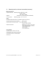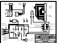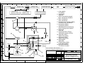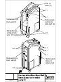
1
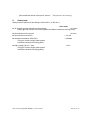
Service Manual
cryoflow 700/1000
Copyrigh© GymnaUniphy NV, 2003
cryoflow® is a registered trademark of NV
Art. Code 300.219 to 300.224 and 300.275
GymnaUniphy NV
Pasweg 6A, 3740 Bilzen, Belgien
Phone +32 (0)89 510 510 Fax +32 (0)89 510 511
www.gymna-uniphy.com
e-mail: [email protected]
Revision directory
Date
Rev.
From
device
No.:
Changes/remarks
Enclosures
Wiring plan 989.030 Sp Bl 1 "Cryoflow 700/1000 Unit Wiring"
Wiring plan 989.030 Sp Bl 2 "Cryoflow 700/1000 Keyboard"
Drawing "Keyboard circuit card (A200)",
Drawing "Block diagram Cryoflow 700/1000"
Drawing "Disassembling housing/treatment tube"
Drawing "Tube connection, device"
Drawing "Handle"
Drawing "Power unit PT 45 C"
Drawing "Valve cooling circuit"
Serviceanweisung Cryoflow 700/1000 – Version 01/2003
Rev. 1.3
Rev. 1.4
09.06.03
26.05.03
06.06.03
10.06.03
10.06.03
06.06.03
06.06.03
Seite 2 von 20
CONTENTS
Page
1. General remarks....................................................................................................................... 4
2. Technical data .......................................................................................................................... 5
3. Functional description .............................................................................................................. 6
3.1
Cold circuit ............................................................................................................................ 6
3.2
Regulating coldness ............................................................................................................. 6
3.3
Cold air control ..................................................................................................................... 6
3.4
De-icing................................................................................................................................. 7
3.5
Measuring fill level ................................................................................................................ 7
4. Errors........................................................................................................................................ 8
5. Assembling/disassembling..................................................................................................... 10
5.1
Opening the device............................................................................................................. 10
5.2
Electronic sub-assemblies.................................................................................................. 11
5.3
Treatment tube ................................................................................................................... 11
5.3.1
Replacing treatment tube................................................................................................ 11
5.3.2
Aligning silicone tube ...................................................................................................... 11
5.4
Cold circuit .......................................................................................................................... 13
6. Settings................................................................................................................................... 14
6.1
Power supply unit voltage .................................................................................................. 14
6.2
Valve on heat exchanger.................................................................................................... 14
6.3
Temperature sensor ........................................................................................................... 15
7. Functional control ................................................................................................................... 17
8. Safety tests............................................................................................................................. 18
9. Maintenance instructions ....................................................................................................... 19
10.
Measuring devices, tools and consumables (summary) ................................................... 20
Serviceanweisung Cryoflow 700/1000 – Version 01/2003
Seite 3 von 20
1.
General remarks
Cryoflow 700/1000 is a mobile therapeutic device, which with the help of a compressor cools a
heat exchanger. Room air is blown by this heat exchanger and it is cooled to
-30 °C. This cold air gets to the skin surface of patients to be treated via flexible tube.
Only accessories and spare parts, listed in the corresponding documentation for Cryoflow
700/1000 (for example, instructions for use, spare part list, price lists) can be used. The actual
prices for accessories and spare parts can be obtained from suppliers.
The Cryoflow 700/1000 cannot be transported over longer distances, while lying, to avoid
damages to the cooling circuit or compressor. There are no problems with normal transport on
the rolls of the device of tilting or lying the device down for short periods. Each time that the
device has been laid down, you must wait at least 30 minutes before turning it on.
Before putting the Cryoflow 700/1000 into operation, read the instructions for use carefully.
Power supply can only take place to a correctly installed isolated ground socket.
Before opening, the device is to be removed from the mains voltage.
Service work, including opening of the device can only be done by people, authorized by the
manufacturer.
We continuously try to keep our products in line with state-of-the art technology. Thus, we
reserve the right to make changes.
Serviceanweisung Cryoflow 700/1000 – Version 01/2003
Seite 4 von 20
2.
Technical data
Power supply
230 V ± 10 %, 50/60 Hz
115 V ± 10 %, 50/60 Hz
External electrical fuses
16 A at 230 V
20 A at 115 V
Device fuse
T10 A E at 230 V
T16 A H at 115 V
Power consumption max.
1000 VA
Protective category
I
Protective type
Type B
Degree of protection
IP 21
Treatment duration
Time operation: 1 to 595 minutes, permanent operation
Air adjustment
10 steps
Air volume, max.
700 or 1000 l/min
Cooling circuit
maintenance free, closed circuit,
Coolant
R 404 A
Dimensions (D xW x H)
550 mm x 365 mm x 1050 mm,
Weight, approx.
85 kg
Operating conditions
+10 °C to +40 °C environmental temperature
Serviceanweisung Cryoflow 700/1000 – Version 01/2003
Seite 5 von 20
3.
Functional description
(See drawing: "Block diagram ")
3.1
Cold circuit
The cold circuit is indicated on the block diagram with a thick black line.
Cold air is generated in a closed cooling system, filled with the coolant R404A. The filled quantity
is indicated on the plate in the device.
The compressor (6) compresses the gaseous coolant from an initial pressure at the
environmental temperature of approx. 0.6 MPa to an operating pressure of 2.5 MPa. Depending
on operating condition, the maximum temperature of the compressed coolant can be approx.
90° C to110° C. The compressed gaseous coolant gets into the condenser (5). The fan (5) blows
room air through the condenser (5). The coolant is cooled and liquefies at a temperature below
55° C. The pressure of the liquid coolant is approx. 1.8 MPa. The air flow of the fan (5) also
cools the surface of the compressor (6). The fan (5) operates at maximum speed and is not
regulated.
The coolant gets into the evaporator (2) thanks to the mechanical filter (4) and valve (3). It is
spread by the nozzle of the valve (3) The heat exchanger (7) cools. The valve (3) has a
temperature-dependent adjusting device, that adjusts the quantity of coolant in such a way that
only minimum temperatures to approx. -40 °C can occur in the evaporator (2). The pressure in
the evaporator (2) is 0.15 MPa to 0.2 MPa.
The evaporator (2) is designed so that only gaseous coolant can get back into the compressor
(6).
Room air is sucked through the filter mat (8) of the fan (1), blown through the heat exchanger (7)
and then gets to the treated surface cooled.
Moisture is removed from the room air in the heat exchanger (7). It freezes and precipitates as
snow. If the cold system is switched off, the snow melts and the liquid collects in the water
vessel (12).
3.2
Regulating coldness
The temperature sensor (9) measures the real temperature on the evaporator (2). The computer
(A100) evaluates the signal analogously and at a lower temperature limit (- 30 °C) it switches off
the compressor (6) and fan of the condenser (5) via the Optor relay and at an upper temperature
limit (- 25 °C) turns them back on.
With this regulation, the compressor operates in an optimum operating range.
3.3
Cold air control
When treatment is started, the Opto relay (11) turns on the ventilator (1). The air flow of the
ventilator (1) can be changed in 10 steps. For this purpose, a pulse-wide modulated signal is
generated by the computer (A100) with a base frequency of approx. 6 kHz, whose periodic has
different impulse break ratio, depending on the air level (20 % at air level 1 to 100 % at air
level10). When treatment is stopped, the Opto relay (11) turns off the ventilator (1).
Serviceanweisung Cryoflow 700/1000 – Version 01/2003
Seite 6 von 20
3.4
De-icing
During treatment, snow (3.10 forms in the heat exchanger. After a few hours, this snow strongly
reduces the set cold air flow (3.3). The heat exchange is no longer optimum and the temperature
of the cold air increases.
The heat exchanger (7) should be de-iced, to return to normal operating conditions.
When the device is turned off, the snow melts completely in about 5 hours.
The resulting water flows into the water vessel (12).
An operating key can also trigger de-icing (see Instructions for use, 7). The Opto relay (10) turns
off the compressor (6) and the ventilator of the compressor (5). The ventilator (1) is turned on by
the Opto relay (11) and warm room air is blown through the heat exchanger (7). Complete deicing takes approx. 30 to 40 minutes at a room temperature of 23 °C.
If the heat exchanger (7) reaches + 8 °C, de-icing is automatically stopped.
The same operating key can be used to stop de-icing.
3.5
Measuring fill level
Water gets into the water vessel (12) due to de-icing (3.4).
From device number 00101 to device number 00325
There is a turnable float with a magnet in the water vessel. At a certain water quantity, the
magnet turns on the level switch (13) (glass tube switch). The compressor (6), ventilator of the
condenser (5) and the ventilator (1) are turned off. A message appears on the display,
mentioning that the water vessel (12) should be emptied.
The level switch (13) is opposite the magnet, on the rear of the recipient for the water vessel
(12). To replace the level switch (13) the recipient of the water vessel (12) and right side wall
(5.1) must be screwed off.
From device number 00326
There is no float with magnet.
3 pressure switches are used as level switch. They are located under the movable recipient of
the water vessel (12). From a certain weight of the water vessel (12), they come on. If the
pressure switches are defective, the recipient for the water vessel (12) must be changed.
Serviceanweisung Cryoflow 700/1000 – Version 01/2003
Seite 7 von 20
4.
Errors
Abbreviations:
SA: Service Instructions
GA:
Instructions for use
No. Error
1 Crash software:
seldom
often
2
3
4
5
6
reproducible
Poor contrast display
Poor cooling
Low air flow
Compressor does not switch
off
Water flows from the device
Possible causes, measures
See
► Turn off device and turn it back on
after 3 minutes
► Control + 5 VDC to computer
A 100 (5,00 V to 5,05 V)
► Replace computer A 100
► Adjust contrast
► Control + 5 VDC to computer
A 100 (5,00 V to 5,05 V)
► Insert plug-in connector for CCFL
illumination onto computer
There is high voltage
► Display is defect
► Check filter mat
► Fan for cooling condenser
(M003) must be operating
► No ice can form to the compressor on
the coolant return line
GA: 11.1
► Check temperature sensor (RT001)
► Extreme environmental conditions
► Have cooling circuit checked
(leak, compressor or valve defect,
adjust valve)
SA: 6.3
► Replace filter mat
► The silicone tube in grip treatment
tube has turned (test: the grip tube can
be turned in handle or in the device
connection)
► Check fixation fan and air guide in the
device
► Check fan (M002)
Test: Pull Bu 001 on fan, fan
operates at maximum speed
► Ice on heat exchanger
► Check temperature sensor (RT001)
► Opto relay (K001) does not switch off
► Fan for cooling condenser (M003)
must operate
► Have cold circuit checked
► Leak in tube guide from heat
Serviceanweisung Cryoflow 700/1000 – Version 01/2003
SA: 6.1
SA: 5.2
GA: 5.4
SA: 6.1
SA: 5.1
SA: 5.1
GA: 11.1
SA: 6.2
GA: 10.
SA: 5.4
SA: 6.2
GA: 11.1
SA: 5.3
SA: 5.1
SA: 5.1
GA: 11.1
SA: 6.3
SA: 5.1
SA: 5.1
SA: 5.4
SA: 5.1
Seite 8 von 20
exchanger to water vessel
► Leak in water vessel
►Check level switch (S002)
► No ice can form to compressor on the
coolant return line
7
Handle and tube iced
8
Compressor is on for a long
phase, without the fan for
cold air (M002) coming on
(long ready phase of device)
► Normal after longer operation and
higher air humidity
Switch-on phase is normal at:
Room temperature to 24°C < 18 Min.
Room temperature to 28°C < 22 Min.
Room temperature to 32°C < 27 Min.
If values are greater, proceed
according to 3 of this error table.
Serviceanweisung Cryoflow 700/1000 – Version 01/2003
SA: 3.5
SA: 6.2
GA: 11.1
GA: 10.
Seite 9 von 20
5.
Assembling/disassembling
5.1
Opening the device
(See drawing "Assembling housing/treatment tube“)
Remove the plug from the socket before opening the device.
Tool for opening the device:
● Hexagon angle screw driver
for hexagon socket head cap screws, 2.5 mm
● Cross recess screw driver, Phillips size 2
These components are located in the console (1)
► Computer card circuit (A100)
► Key board cad circuit (A200)
► Display (A500)
These components are located to the right behind the side wall (2)
► Power supply (A300)
► Mains filter (A200)
► Opto relays (K001, K002)
► Connection X 019 (RT001, SOO2)
Plate with filled quantity for RA404A
These components are located to the left behind the side wall (3)
► Distributor box (A400)
► Valve on heat exchanger
► Connection Bu 001 (M002)
Open up console (1):
(1.1) ● screw out 4 hexagon socket head cap
Screws under the console,
Fold up console in the direction of the mains
switch
Remove (2.1) right side wall (2) : (2.1)
● loosen 2 hexagon screws, but do not
screw them out
● Screw out 2 cross recess screws
(2.2)
Remove left side wall (3):
● See removing right side wall (2)
(3.1) ● screw out additional 1 cross recess screw
Remove rear wall (4):
(4.1)
Remove front wall (5):
Serviceanweisung Cryoflow 700/1000 – Version 01/2003
● screw out 4 cross recess screws
● Remove right side wall (2)
● Remove left side wall (3)
● Screw out 4 cross recess screws
Seite 10 von 20
5.2
Electronic sub-assemblies
All electronic sub-assemblies are connected with plug-in connectors or screwed terminals.
Sub-assemblies are easily accessible after the device is opened (5.1).
Tool for changing sub-assemblies:
Drew driver for recess screws:
Size 3 mm, 5.5 mm,
8 mm (air tube in device, M002)
Screw driver for cross recess screws:
Phillips size 2
Open end wrench
Width 5 mm, 5,5 mm, 7 mm, 8 mm,
14 mm (safety holder),
27 mm (mains line)
5.3
Treatment tube
5.3.1 Replacing treatment tube
(See drawing "Disassembling housing/treatment tube")
Remove tube (6):
(6.1)
● screw out 4 cross recess screws
Other tool: screw driver for cross recess screws Phillips size 2
The complete tube can be pulled out of the heat exchanger (device) with the flange.
Insert the new tube into the heat exchanger and fasten it with the 4 screws. Make sure that the
sealing rubber is not damaged.
5.3.2 Aligning silicone tube
(See drawing "Tube connection, Device " and "Handle")
If the quantity of cold air through the treatment tube is strongly reduced, the inner silicone tube is
possibly twisted and is not smooth on the ripple tube.
These are possible causes of twisting:
A:
(See drawing "Tube connection, device")
Part (3) can twist in Part (4)
B:
See drawing "Tube connection, device"
Ripple tube can twist into part (3)
C:
See drawing "Handle"
Ripple tube can twist into Part (7)
Control:
To A, B:
pressure
To C:
Hold ripple tube on the end of the flange (5) and try to turn it with slight
Hold handle and ripple tube and try to turn them against one another
Serviceanweisung Cryoflow 700/1000 – Version 01/2003
Seite 11 von 20
with slight pressure
The final confirmation, whether the silicone tube is twisted, results from visual control in
the inside of the treatment tube.
The treatment tube is to be screwed from the device according to 5.3.1.
Other tool:
Material:
cross recess screw driver, Phillips: size 1
Screw driver for recess screws:
Size 3 mm
Cable binder 165 mm X 2,5 mm, 4 pieces
Zyanakrylat-adhesive (second quick adhesive), 0.5 mL
Visual control:
(See drawing "Handle")
Screws (1) must be loosened
Remove cap (3) and clamp ring (4)
The treatment tube must be held in stretched length against the light and it
must be looked through it
Repair:
To A, B:
(See drawing "Tube connection, device")
Loosen screws (1)
Parts (2), (3) and (4) must be removed from the flange (5)
Part (2) with the silicone tube is to be removed from parts (3) and (4)
Part (3) is to be held and is turned with part (2) so that it is smooth on the
ripple tube .
(Sometimes, a round rod, for example, a broom handle should be inserted.
With such a help, the twisting of the the silicone tube can be easily carried out.)
If the holes for the screws (1) are turned against one another,
they must be aligned.
The cable binders which is in part to hold the silicone tube on part (2) are to
to be cut. Part (2) is to be turned in the silicone tube so that the holes
match again. The silicone tube is to be fastened with two new
cable binders to part (2).
The ring (4), must be glued to part (3).
The ring (4) is to be spread with a screw driver. A few drops of glue are to be
placed in the opening between ring (4) and part (3). The screw driver
is to be removed.
If the ripple tube moves in part (3) it is to be glued on several sites
with the part (3). An opening is created between the ripple ruge and the part (3)
by a screw driver, in which a few drops of glue are placed.
To C:
(See drawing "Handle")
Parts (5), (6) and(7) are to be removed with the ripple rube with the handle (I8).
If the ripple tube moves in the part (7), it must be glued at several sites
with part (7). An opening is to be created between the ripple tube and
part (7) with a screw driver. A few drops of glue are placed into this
opening.
ATTENTION
Before and during gluing, it must be ensured that the holes for the screws fit and are not twisted.
Serviceanweisung Cryoflow 700/1000 – Version 01/2003
Seite 12 von 20
After assembling the treatment tube to Cryoflow 700/1000 the ripple tube cannot turn when the
handle is hung into the hole on the device. If there is such a twisting, the tube connection is to be
aligned to the device according to A;B and glued again.
5.4
Cold circuit
(See drawing "Block diagram")
Repairs and replacing of sub-assemblies within the closed cold circuit are to be
performed only by an expert company for cold or air conditioning technology.
When the cold circuit is filled, attention must be paid to:
► The quantity of required coolant is on the plate near the power supply unit.
Depending on design, 500 grams to 700 grams are to be filled in.
The indicated filled quantity on the plate must be complied with (± 10 g).
► Before the cold circuit is filled, a vacuum pump is to be connected and operated
longer than 30 minutes.
The measuring device of the fittings must have sufficient vacuum for this coolant.
► Filling must be done with liquid gas. The gas bottle is thus to be set with the head
on a balance. The weight difference between beginning and end of filling (first step
and second step) is the filled quantity.
First step:
-compressor is switched off
- Liquid gas is let in, approx. 50 % of the indicated filled quantity
- Turn off gas bottle
Second step: - Switch on compressor
- Open gas cylinder
- Fill rest quantity
Serviceanweisung Cryoflow 700/1000 – Version 01/2003
Seite 13 von 20
6.
Settings
6.1
Power supply unit voltage
(See drawing: "Power supply unit PT 45 C")
Console and right side wall are to be removed according to 5.1.
Other tool:
Screw driver for recess screws, size 3 mm
Measuring instrument:
Voltage measuring instrument range 10VDC
Control of +5 V on plug-in socket con 112 (Pin 2, 3) on the controller board (A100)
and the setting of this voltage with R7 on the power supply unit (A300) is necessary in the case
of the following errors:
► Software crash
► Low contrast in display
Measuring point:
con 112, Pin 2,3 against Pin 4,5 on controller board (A100)
Setting area: +5,00 V to +5,05 V
Setting point:
R 7 on power supply unit (A300),
(Turn regulator to the right and voltage increases)
6.2
Valve on heat exchanger
(See drawing "Valve cooling circuit")
Setting of the valve is necessary in case of icing of compressor on the return connectors.
Screw off left side wall (5.1)
Other tool:
Material:
Open end wrench, width 19 mm
Knife
Screw driver for recess screws, size 5.5 mm,
Clock
Self-adhesive foam insulating tape (can be obtained in commerce)
The vale is insulated with foam and around the size of a fist.
It is below the fan (M002), directly on the heat exchanger.
According to the drawing "Valve cooling circuit " Position (5), the insulation of the valve is to be
cut from the rear wall by approximately 5 cm. The visible protective cap (6) is to be removed.
Setting on the screw (7) depends on the icing area on the compressor (return connectors) per
time unit and is to be carried out according to then following table:
Icing area on compressor
within 15 minutes (M002 is out):
< 10 cm2
< 30 cm2
< 100 cm2
< 200 cm2
Serviceanweisung Cryoflow 700/1000 – Version 01/2003
Turn screw (7) to the right ,
1 X ist 90 °, ¼ turn:
1X
2X
3X
4X
Seite 14 von 20
The test follows after setting. The device is switched on and permanent treatment is started. The
fan M002 is off. The time in which the compressor operates is to be measured. The setting is
completed in case of:
Operating time < 10 minutes at 25° C room temperature and no icing
Operating time < 12 minutes at 30° C room temperature and no icing
If these values are not complied with, setting is repeated.
Before the new measurement, the device must be de-iced (3.4). The process is automatically
stopped, when the heat exchanger reaches + 8 °C.
After the setting, the cap (6) is screwed back onto the valve; the insulation is thoroughly closed
and glued with additional insulating tape.
6.3
Temperature sensor
The temperature sensor is located behind the right side wall and is plugged into the heat
exchanger with a screwed cable guide.
It can be removed by screwing out the cable guide and replaced.
Control temperature sensor:
Screw off right side wall (5.1)
Other tool:
Screw driver for recess screws: size 3 mm
Resistance measuring device with test terminals
Measuring range 0.5 – 1.5 kOhm
The temperature sensor must be on the measuring area with a pressure in the heat exchanger:
► The cable guide must be screwed on. The cable for the temperature sensor is now
movable. It is pressed into the heat exchanger with the cable.
Pressure is now used to screw the cable guide again.
Functional control:
► Loosen cable on X 019 and clamp to the resistance measuring device.
Resistance table of temperature sensor:
T[°C]
-40
-35
-32
-30
-28
-26
-24
-22
-20
-18
-16
-14
R[Ohm]
562
589
607
617
627
640
652
664
677
689
702
715
T[°C]
-12
-10
-8
-6
-4
-2
0
2
4
6
8
10
R[Ohm]
728
740
753
766
780
794
807
821
835
849
864
877
T[°C]
12
14
16
18
20
22
24
26
28
30
35
40
R[Ohm]
892
907
922
937
951
966
982
998
1014
1029
1070
1111
The device is switched on and permanent treatment is started. The fan M002 is off. The cooling
system and temperature measurement function, when the following values are reached:
Serviceanweisung Cryoflow 700/1000 – Version 01/2003
Seite 15 von 20
-30 °C within 16 minutes to 24° C room temperature
-30 °C within 19 minutes to 28° C room temperature
-30 °C within 23 minutes to 32° C room temperature
Serviceanweisung Cryoflow 700/1000 – Version 01/2003
Seite 16 von 20
7.
Functional control
Please comply with instructions for use.
The nozzle 25 mm is to be used. Smaller nozzles are to be screwed from the handle.
Functional control is to be carried out in the order given, without interruption.
► Time operation:
Set 1 minute, start, change air levels, air flow must change, fan (M002)
switches off after 1 minute
► Permanent operation:
start, change air level, air flow must change,
Trigger level switch (S002) for water vessel (for example
filling water into the water vessel, compressor and fan switch off and this
message appears in the display: "Empty water vessel"
► Turn device off and back on after approx. 2 minutes:
Last operating mode appears on the display,
Compressor operates (measuring time) and switches off at:
< 16 minutes (room temperature to 24° C)
< 19 minutes (room temperature to 28° C)
< 23 minutes (room temperature to 32° C)
► Permanent operation:
start, set air level 5, clock shows the treatment time.
► Temperature measurement:
after approx. 15 minutes of treatment:
(All systems and tube should be cooled, to obtain comparable measured
values)
Place thermometer in the middle of the nozzle opening. It cannot be on the
wall:
18° C room temperature: -12 °C ± 4 °C cold air temperature
24° C room temperature: -10 °C ± 4 °C cold air temperature
32° C room temperature: -6 °C ± 4 °C cold air temperature
(The measured temperatures depend on relative air humidity)
► Permanent operation:
stop
► De-icing:
start
(The process can be stopped only after approx. 3 minutes.)
The key "de-icing " is blocked for protection of the compressor at the
beginning .)
► System setting: if settings, such as language, contrast, key tone, sound,
"End of treatment" or signal level are to be changed, please
proceed according to 5.4 of Instructions for Use.
If only the temperature of cold air is to be measured, this procedure is to be followed:
Turn on device, start no treatment (heat exchanger is cooled)
After 10 minutes, start permanent treatment, and set air level 5
After 15 minutes of permanent treatment, measurement is to be done
The 25 mm nozzle is to be used. Smaller nozzles are to be screwed from the handle.
The thermometer is inserted in the middle of the nozzle opening.
It cannot be on the wall.
Serviceanweisung Cryoflow 700/1000 – Version 01/2003
Seite 17 von 20
(See measured values in this point, section "
8.
Temperature measuring")
Safety tests
Safety tests are performed according to EN 60 601-1 or IEC 601-1.
Limit value
► 10 A-safety ground resistance measurement:
< 0,2 Ohm
(safety ground of mains connection against touchable conductive housing parts)
► Ground lead off current NC:
► Ground lead current SFC:
< 0,5 mA
< 1,0 mA
► Insulation resistance (500 VDC):
(Plug pin of mains supply lead against
touchable conductive housing parts)
> 2 MOhm
► High voltage (50 Hz, 1 min):
(Plug pin of mains supply lead against
touchable conductive housing parts)
1.5 kV
Serviceanweisung Cryoflow 700/1000 – Version 01/2003
Seite 18 von 20
9.
Maintenance instructions
Before performing all maintenance and repair work to Cryoflow 700/1000, the device must be
switched off and removed from the mains. Device and accessories can be wiped with a dry or
wet cloth. In case of hard-necked spots, use a non-aggressive soap solution.
Attention: No moisture can get into the device or accessories.
Carefully dry all parts.
The filter mat is to be washed regularly in soap solution or replaced. They can be simply
removed from their location.
Please insert only dry filter mats.
The water vessel (behind the flap on the rear wall) is to be cleaned regularly with a soap
solution.
We recommend area disinfectant based on aldehyde, alcohol, or quaternary ammonium
compounds for the disinfection of device and water vessel.
Due to possible damage of the material, preparations based on halogen and oxygen splitting
compounds, strong organic acids, solvents, benzene, acetone and similar substances are not
suitable.
Serviceanweisung Cryoflow 700/1000 – Version 01/2003
Seite 19 von 20
10.
Measuring devices, tools and consumables (summary)
Measuring devices:
● Digital multimeter Measuring range: 250 VAC, 10 AAC
20 VDC, 1ADC
Ohm, kOhm, MOhm
● Watch
● Thermometer
(stop watch or wrist watch with second hand)
Measuring range: -30 °C to +40 °C
Tools:
● Hexagon angle screw driver, for hexagon screws, size 2.5 mm
● Cross recess screw driver, Phillips:
● Screw driver for recess screws :
Size 1 and 2
Size 3 mm, 5.5 mm,
8 mm (air tube to M002)
● Open end wrench
Width 5 mm, 5,5 mm, 7 mm, 8 mm,
10 mm (tube connection to M002)
14 mm (safety holder),
19 mm (valve)
27 mm (mains line)
Consumables:
● Cable binders, 165 mm x 2.5 mm
● Zyanakrylat- glue (second quick glue)
● self-adhesive foam –insulating tape
● Filter mat
Serviceanweisung Cryoflow 700/1000 – Version 01/2003
Seite 20 von 20
1
2
3
4
Bu001
St001
Ub
A500
St0 02
M002
D
PW M
Gnd
W515
5
M
W513
Bu002
K002
L
N
PE
D
FAN
PATIENT
con513
W015
con515a
con215a
X016
con215
RT001
S002
LEVEL SW ITCH
KTY81-121
M003
X017
M
X019
Display
A400
M001
A100 Display
C001
88uF
K003
X018
330V
K002
St213
Bu213
COMPRESSOR
FAN
COMPRE SSOR
K001
X015
C
C
A200
2N
A100
Keyboard
A100
Enc. A
A100
Fan
A100 US PCB
X014
con205
Bu311
con204
W004
con211
con203
W011
W003
con111
con103
-15V
gnd
gnd
+5V
+5V
+15V
W005
Bu302
K001
N
3L
L
SMPS
PT 45C
A300
X013
con105
con104
St3 02
St311
B
B
US PCB
Enc. A
Console
Fan
Power Supply
A002
A001
Display
X021
X022
F001
A100
X001
X006
X002
X005
X003
X004
X007
X009
X011
X008
X010
X012
Backl ight
VLK101
con112
Bu312
X023
con113
X020
con115
W513
POWER CO RD
F002
FILTER
W015
Property of:
A
Design by:
A
2003/05/19
2003/05/22
Drawn by:
Approval:
Title
Pinout only valid for
ELAL013Lo100v0.0
Size
Document
Re v
Sheet
1
2
3
4
5
of
1
2
3
Con211
1
2
3
4
5
6
A100
Rotary 1
1
2
3
4
5
6
A100
Keyboard
5
Con215a
C215
100U
25V
D
+5V
+15V
V202
150
R202
2
150
2
+5V
+30V
R213
33
4W
10%
R214
150
4W
10%
2
4
6
-UA
+UA
2
UE+
UENC
1
1
N201
1
2
5
DC/DC 5-1515
US_CON1 (Q103 + 22E)
+5V
+5V
POR\
USI_SENSE (P5.7 AD C)
VUS_SET (ANALOG OUT)
US_SCK (P3.4 + 10K PU)
+5V
A
1
150
R212
V203
2
1K
1
2
R208
1
12K
R207
2
1K
+5V
1N4148
2
V205
BC337
V206
BC337
150
+
+
+
+
+
+
+
+
+
+
+
+
+
+
+
+
+
+
+
+
2
4
6
8
10
12
14
16
18
20
US_CON2 (Q105 + 22E)
USV_SENSE (P5.6 ADC)
-5V
US_DC (P3.3)
US_SDA (P3.5 + 10K PU)
B
A100
Ultrasound
1
1
1K
Prope rty of:
Design by:
2
R210
2
1K
R206
1
2K2
1
1
3
5
7
9
11
13
15
17
19
+15V
R209
2
R211
Signal
Fan On/Off (K0 01)
Temperatur e Sensor
Vcc
Water Container
Measurement Gnd
Compressor On/Off (K001)
Fan PWM signal
Fan Ub 30V
Fan Gnd
Drawn by:
Con203
3
2
1
VCC
FAN (SINK)
TH.SENSOR
A100
Fan
A
Approval:
Title
Size
Document
Rev
Sheet
1
C
V204
BC337
2K2
1
R205
2
Pin#
9
8
7
6
5
4
3
2
1
1N4148
2
V207
9
8
7
6
5
4
3
2
1
R204
1
B
St213
A100
Display
Con205
Cryoflow
Componen ts
+5V
D0
D1
D2
D3
OFF\
FRAME
nc
LOAD
CP
VDD
VSS
VEE
VO
FGND
1
2
3
4
5
6
7
8
9
10
11
12
13
14
GN
R201
ENCODER
MRTC25
+5V
D
Con215
1
YE
1
S204
S203
S202
S201
1
2
3
4
5
C
Cryoflow
Display
+5V
V201
St201
D201
FRAME
LOAD
CP
VDD
VSS
VEE
D0
D1
D2
D3
OFF\
nc
1
2
3
4
5
6
7
8
9
10
11
12
1
2
3
Con204
4
2
3
5
of
Anwenderseite
user side
09.06.03
Netzteil A300
(Power supply A300)
Rechner A100
(Controller A100)
Tastatur A200
(Keyboard A200)
Anzeige A500
(Display A500)
Netzschalter S001
(Power switch S001)
Verteilerkasten A400
(Terminal box A400)
L/H
10
5
6
11
4
L/H
9
3
14
(St001)
kalte Luft
(cold air)
PWM
Raumluft
(Environment air)
8
Sicherung / Netzkabel
(Fuse / Power cord)
1 - Lüfter (M002)
Fan (M002)
2 - Verdampfer
Vaporizer
3 - Ventil, mechanisch geregelt
Valve, mechanical controlled
4 - Filter, mechanisch
Filter, mechanical
5 - Kondensor mit Ventilator (M003)
Condensor with Fan (M003)
6 - Kompressor (M001)
Compressor (M001)
7 - Wärmetauscher mit Isolierung
Heat exchanger with isolation
8 - Filtermatte
Filter mat
9 - Temperaturfühler (RT001)
Temperature sensor (RT001)
10- Optorelais (K001)
Optical relay (K001)
11- Optorelais (K002)
Optical relay (K002)
12- Wassergefäß
Water tank
13- Pegelschalter (S002)
Level switch (S002)
14- Kreislauf Kühlmittel
Circulation of coolant
Hierzu Schaltplan 989.030 SP Bl.1 u. 2
To this wiring diagramm 989.030 Sp Bl.1 a. 2
1
(X019)
Filter
A002
7
2
13
12
Blockschaltbild
(block diagramm)
cryoflow 700
Pult (1)
desk (1)
1.1
2.1
Vorderwand (5)
front wall (5)
Behandlungsschlauch (6)
tube for treatment (6)
4.2
Seitenwand,
rechts (2)
side right (2)
2.2
1.1
6.1
3.1
Rückwand (4)
back wall (4)
4.1
06.06.03
Seitenwand,
links (3)
side left (3)
Schlauchendstutzen (geräteseitig)
connection to device
2
Anschluss für Silikonschlauch
connection for silicon tube
4 Ring
ring
1
Nach der Montage Ring (4)
spreizen und verkleben
after assembly ring (4) splay
and glue on
2
3
5 Flansch
flange
Position für Ring (4)
position for ring (4)
3
Riffelschlauch eingeschraubt und verklebt
tube with groove screw in and glue on
10.06.03
1 Schraube 3x25
screw 3x25
4
Düse
noozle
3
Kappe
top
4
Klemmring
ring to clip
5
Haken
hook
1
4
2
2 Schraube 3x30
screw 3x30
8
7
7
Griff
grip
10.06.03
Schraube M3x10
screw M3x10
5
6
6
8
1
FS1
CN1
CN2
6543 21
R7 - Einstellregler (variable resistance)
FS1: 4A, 250V
CN1: 100-240VAC, 1A
CN2: Pin 1 : +15V, 1,6A
Pin 2, 3: +5V, 3A
Pin 4, 5: GND
Pin 6 : -15V, 0,3A
Einstellung +5V: R7 nach rechts drehen, Spannung wird größer
Tuning +5V
: R7 turn right, voltage becomes higher
06.06.03
1 Wärmetauscher, isoliert
Heat exchanger with
isolation
2 Rücklauf Kühlmittel,
isoliert
repatriation of coolant
with isolation
1
2
3 Lüfter (M 002)
Fan (M 002)
3
4 Ventil, isoliert
Valve with isolation
4
5
5 Isolation aufschneiden
Cut isolation to open
6 Kappe abschrauben
screw off top
7 Einstellschraube
screw to set
4
6
7
nach rechts drehen
turn to the right
06.06.03