1
Cary
100/300/4000/5000/
6000i
Spectrophotometers
Hardware Operation Manual
Installation Category II
Pollution Degree 2
Safety Class 1 (EN61010-1)
NOTICE: This document contains references to Varian.
Please note that Varian, Inc. is now part of Agilent
Technologies. For more information, go to
www.agilent.com/chem.
Publication No. 8510197200
Issue 03
May 2010
Cary 100/300/4000/5000/6000i Hardware Operation Manual
Varian, Inc. – Serving Industries Worldwide
Biosciences
Pharmaceuticals
Clinical Research and Forensics
Food and Agriculture
Chemical Analysis
Environmental
Fuels and Energy
Material Sciences
Sales and Service Contact Details
North America: 800.926.3000, 925.939.2400
Europe, The Netherlands: 31.118.67.1000
Asia Pacific, Australia: 613.9560.7133
Latin America, Brazil: 55.11.3238.0400
Varian, Inc. Web Site
www.varianinc.com
Varian, Inc. is the owner of copyright on this document and any
associated software. Under law, the written permission of Varian,
Inc. must be obtained before the documentation or the software is
copied, reproduced, translated or converted to electronic or other
machine-readable form, in whole, or in part.
First published May 2002. Updated June 2002 and May 2010.
Cary, Varian and the Varian logo are trademarks or registered
trademarks of Varian, Inc. in the U.S. and other countries.
Microsoft Windows and Windows XP are registered trademarks of
Microsoft Corporation in the United States and other countries.
© 2010 Varian Inc.
ii
Publication no. 8510197200, Issue 03, May 2010
Cary 100/300/4000/5000/6000i Hardware Operation Manual
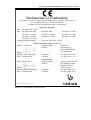
Declaration of Conformity
We hereby declare that the equipment listed below complies with the requirements of:
The Low Voltage Directive 73/23/EEC (93/68/EEC)
The EMC Directive 89/336/EEC (92/31/EEC and 93/68/EEC)
Applicable Standards
LVD
EMC
BS EN 61010-1:1993
BS EN 61326:1998
IEC1000-3-3:1994
IEC1000-4-4:1995
IEC1000-4-11:1994
Equipment Model Number
Name: G. A. Wassink
EN55022:1994
IEC1000-4-2:1995
IEC1000-4-5:1995
IEC1000-3-2:1995
IEC1000-4-3:1998
IEC1000-4-6:1996
Cary 100, 300 Series II Series
Authorized Representative in the EU
Company Name
Varian BV
Address
Herculesweg 8,
4330 EA Middelburg
The Netherlands
Signed:
Position: Quality Manager
Date: 1 October 2001
Name: Gregory Davis
Signed:
Position: Managing Director
Date: 1 October 2001
Telephone
Facsimile
Manufacturer
Company Name
Address
Telephone
Facsimile
+31 (0) 118 671 000
+31 (0) 118 633 118
Varian Australia Pty Ltd
679 Springvale Road
Mulgrave Victoria
3170 Australia
+61 (0) 3 9560 7133
+61 (0) 3 9560 7950
Publication number 8510 189800 10/01
Publication no. 8510197200, Issue 03, May 2010
iii
Cary 100/300/4000/5000/6000i Hardware Operation Manual
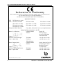
Declaration of Conformity
We hereby declare that the equipment listed below complies with the requirements of:
The Low Voltage Directive 73/23/EEC (93/68/EEC)
The EMC Directive 89/336/EEC (92/31/EEC and 93/68/EEC)
Applicable Standards
LVD
EMC
BS EN 61010-1:1993
BS EN 61326:1998
IEC 61000-3-2:1995
EN 61000-4-4:1995
EN 61000-4-11:1994
Equipment Model Number
Name: G. A. Wassink
EN 55011:1998
IEC 61000-3-3:1995
IEC 61000-4-5:1995
EN 61000-4-2:1995
IEC 61000-4-3:1995
IEC 61000-4-6:1996
Cary 4000, 5000, 6000i series spectrophotometers
Authorized Representative in the EU
Company Name
Varian BV
Address
Herculesweg 8,
4330 EA Middelburg
The Netherlands
Signed:
Position: Quality Manager
Date: 1 April 2002
Name: Gregory Davis
Signed:
Position: Managing Director
Date: 1 April 2002
Telephone
Facsimile
+31 (0) 118 671 000
+31 (0) 118 633 118
Manufacturer
Company Name
Address
Telephone
Facsimile
Varian Australia Pty Ltd
679 Springvale Road
Mulgrave Victoria
3170 Australia
+61 (0) 3 9560 7133
+61 (0) 3 9560 7950
Publication number 8510196600 04/02
iv
Publication no. 8510197200, Issue 03, May 2010
Cary 100/300/4000/5000/6000i Hardware Operation Manual
Table of Contents
Safety Practices and Hazards
1
Ultraviolet Radiation
1
Electrical Hazards
2
Other Precautions
3
Warnings and Cautions
3
Color Coding
5
Information Symbols
5
US FCC Advisory Statement
5
CE Compliant Products
6
1.
1
Introduction
1.1 Installation Requirements
1
1.2 Cary Documentation
1
1.3 Specifications
1
2.
1.3.1
Environmental
2
1.3.2
Power
2
1.3.3
Gas Supplies
4
1.3.4
Weights and Dimensions
4
Installation
2.1 PC Hardware Installation
5
5
2.1.1
Lifting the Instrument
5
2.1.2
Installation Checklist
6
2.2 GPIB Communications Card
8
2.2.1
Installing the PCI-GPIB Communications Card
2.2.2
Installing USB-GPIB-HS Convertor
2.3 Instrument Setup
2.3.1
Cabling
Publication no. 8510197200, Issue 03, May 2010
8
12
12
12
v
Cary 100/300/4000/5000/6000i Hardware Operation Manual
2.3.2
Power
13
2.4 Starting the System
13
2.5 Instrument Performance Tests
14
2.6 Sample Holders
15
2.6.1
Cell Holders—Cary 100/300
15
2.6.2
Cell Holders—Cary 4000/5000/6000i
16
2.6.3
Aligning the Single Cell Holder
17
2.6.4
Solid Sample Holder—Cary 4000/5000/6000i
18
2.6.5
Aligning the Solid Sample Holder
21
2.7 Installing the Base Plate Using the LockDown Mechanism 23
2.8 Installing Other Accessories
23
2.9 Nitrogen Purging
23
2.9.1
Nitrogen Purging System—Cary 4000/5000/6000i
23
2.9.2
Purging Procedure
25
2.9.3
Nitrogen Purging—Cary 100/300
26
2.10 Sample Compartment Base Removal
3.
vi
26
2.10.1
Cary 100/300
26
2.10.2
Cary 4000/5000/6000i
26
Maintenance
29
3.1 Cleaning
29
3.2 Source Lamps
30
3.3 Fuses
30
3.4 Spare Parts
32
Publication no. 8510197200, Issue 03, May 2010
Cary 100/300/4000/5000/6000i Hardware Operation Manual
Safety Practices and Hazards
Your Varian Cary instrument and accessories have been carefully
designed so that when used properly you have an accurate, fast,
flexible and safe analytical system.
If the equipment is used in a manner not specified by the
manufacturer, the protection provided by the equipment may be
impaired.
Information on safety practices appears throughout the
documentation (both printed and on-line) provided with your
instrument and accessories. Before using the instrument or
accessories, you must thoroughly read these safety practices.
Observe all relevant safety practices at all times.
Ultraviolet Radiation
The Deuterium (standard in all instruments) and Mercury lamps (if
fitted) in the instrument emit hazardous UV radiation. This radiation
can cause serious damage to eyes. NEVER look directly at either
lamp and NEVER operate either lamp unless it is mounted
correctly in the lamp turret (Cary 4000/5000/6000i only) and the
turret is mounted correctly in the instrument.
Note
The mercury lamp is fitted as standard in the Cary
4000/5000/6000i.
Ozone can be generated by radiation from the source lamps.
Exposure to ozone can result in severe irritation to the skin, eyes,
and upper respiratory system. The maximum permissible exposure
3
level is 0.1 ppm (0.2 mg/m ).
ALWAYS ventilate the area surrounding the spectrophotometer
such that the concentration of ozone does not exceed the
maximum permissible level. All venting must be to outside air,
never within the building.
Publication no. 8510197200, Issue 03, May 2010
1 of 32
Cary 100/300/4000/5000/6000i Hardware Operation Manual
Electrical Hazards
The Cary 100/300/4000/5000/6000i instruments and some
accessories contain electrical circuits, devices, and components
operating at dangerous voltages. Contact with these circuits,
devices and components can cause death, serious injury, or
painful electrical shock.
Panels or covers which are retained by screws on the
spectrophotometer and accessories (with the exception of the lamp
access cover) may be opened ONLY by Varian-trained, Varianqualified, or Varian-approved service engineers. Consult the
manuals or product labels supplied with your PC, monitor and
printer/plotter to determine which parts are operator-accessible.
Operators and other unauthorized personnel are permitted access
ONLY to the lamp compartment and the sample compartment of
the Cary. ALWAYS switch off the spectrophotometer before
changing a lamp in the lamp compartment.
Good grounding/earthing is essential to avoid a potentially serious
electric shock hazard. Ensure that there is an integral ground
connection between the metal base of the spectrophotometer and
accessories and the 3 pin earth-grounded receptacle. Consult the
manuals or product labels supplied with your PC, monitor and
printer/plotter for the relevant grounding requirements.
Note
The safety classification is given as Class 1 (EN 61010-1).
Application of the wrong supply voltage can create a fire hazard
and a potentially serious shock hazard, and could seriously
damage the Cary system, accessories and any attached ancillary
equipment. The Cary 4000/5000/6000i has a Universal Power
Supply that adapts to the supply voltage. However, care must be
taken to ensure that the correct voltage is used.
Do not connect the spectrophotometer or accessories to the mains
power supply until you have made sure that the slide switch(es)
(Cary 100/300 only) at the rear of these are correctly set for the
mains power supply in the specific outlet in your laboratory to
which the equipment will be connected. Consult the manuals
supplied with your PC, monitor and printer/plotter for their specific
voltage requirements.
Replace blown fuses with fuses of the size and rating as stipulated
in the text adjacent to the fuse holder or in the manuals where
listed.
Do NOT use power cords with faulty or frayed insulation.
2 of 32
Publication no. 8510197200, Issue 03, May 2010
Cary 100/300/4000/5000/6000i Hardware Operation Manual
Other Precautions
Both the deuterium and the visible lamps operate at high
temperatures, and touching either of these lamps may result in
burns. Before replacing a lamp that has been lit, switch off the
spectrophotometer and either ensure that the lamp has cooled, or
protect your fingers from burns.
Do not block the ventilation grills on the spectrophotometer and
accessories. Consult the manuals supplied with your PC, monitor
and printer/plotter for their specific ventilation requirements.
Use of the Cary system and accessories may involve materials,
solvents and solutions which are flammable, corrosive, toxic or
otherwise hazardous.
Careless, improper, or unskilled use of such materials, solvents
and solutions can create explosion hazards, fire hazards, toxicity
and other hazards which can result in death, serious personal
injury, and damage to equipment and property.
ALWAYS ensure that laboratory safety practices governing the
use, handling and disposal of such materials are strictly observed.
These safety practices should include the wearing of appropriate
safety clothing and safety glasses.
Warnings and Cautions
Other specific warnings and cautions appear in this manual and in
the on-line help where appropriate, and will detail the specific
hazard, describe how to avoid it, and specify the possible
consequences of not heeding the warning or caution.
Warning
A ‘Warning’ message appears in the manual when failure to
observe instructions or precautions could result in death or
injury. Symbols depicting the nature of the specific hazard are
also placed alongside warnings.
Caution
A ‘Caution’ message is used when failure to observe instructions
could result in damage to equipment (Varian supplied and/or
associated equipment).
A ‘Note’ is used to give advice or information.
Publication no. 8510197200, Issue 03, May 2010
3
Cary 100/300/4000/5000/6000i Hardware Operation Manual
Read all warnings and cautions carefully and observe them at all
times.
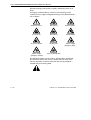
A triangular symbol indicates a warning. The meanings of the
symbols that may appear alongside warnings in the documentation
are as follows:
Electrical shock
Eye hazard
Noxious gases
Hot surfaces
Fire hazard
Sharp Object
Corrosive liquids
Moving part
Heavy weight
(danger to feet)
Heavy weight
(danger to hands)
Part can be ejected
The following symbol may be used on warning labels attached to
the instrument. When you see this symbol you must refer to the
relevant operation or service manual for the correct procedure
referred to by that warning label.
4 of 32
Publication no. 8510197200, Issue 03, May 2010
Cary 100/300/4000/5000/6000i Hardware Operation Manual
Color Coding
The various indicator lights appearing on the Cary
100/300/4000/5000/6000i instruments and any associated
accessories have been color coded to represent the status of the
instrument or accessory:
A green light indicates the instrument is in normal/standby
condition.
An orange light indicates that a potential hazard is present.
A blue light indicates that operator intervention is required.
A red light warns of danger or an emergency.
Information Symbols
The following symbols appear on the Cary
100/300/4000/5000/6000i instruments to provide you with
additional information:
I
0
Mains power on
Mains power off
Fuse
Single phase alternating current
When attached to the rear of the product, indicates that
the product complies with the requirements of one or
more EU Directives
Focus
Vertical adjustment
Horizontal adjustment
US FCC Advisory Statement
This equipment generates, uses and can radiate radio frequency
energy, and if not installed and operated in accordance with the
instruction manual may cause interference to radio
communications. It has been tested and found to comply with the
limits for a Class A computing device pursuant to Subpart J of Part
15 of Federal Communications Commission (FCC) Rules, which
are designed to provide reasonable protection against such
interference when operated in a commercial environment.
Operation of this equipment in a residential area may cause
interference, in which case the user will be required to take
Publication no. 8510197200, Issue 03, May 2010
5
Cary 100/300/4000/5000/6000i Hardware Operation Manual
whatever measures may be necessary to correct the interference
at his or her expense.
CE Compliant Products
Cary instruments have been designed to comply with the
requirements of the Electro-magnetic Compatibility (EMC) Directive
and the Low Voltage (electrical safety) Directive (commonly
referred to as the LVD) of the European Union.
Varian has confirmed that each product complies with the relevant
Directives by testing a prototype against the prescribed EN
(European Norm), IEC or CISPR standards.
Proof that a product complies with the Directives is indicated by:
the CE Marking appearing on the rear of the product
the documentation package that accompanies the product
containing a copy of the Declaration of Conformity. This
Declaration is the legal declaration by Varian that the product
complies with the Directives, and also shows the EN standards
to which the product was tested to demonstrate compliance.
It is also signed by Varian's Authorized Representative in the EU,
and by the representative of the manufacturing plant.
6 of 32
Publication no. 8510197200, Issue 03, May 2010
Cary 100/300/4000/5000/6000i Hardware Operation Manual
1.
Introduction
1.1
Installation Requirements
Prior to receiving your Cary instrument you will have been provided
with a Cary Pre-installation manual (publication number
8510128000), which describes the environmental and operating
requirements of the Cary system. You must prepare your
laboratory according to these instructions before the Cary can be
installed. You should keep the Pre-installation manual for future
reference. If you have misplaced your copy, you can obtain a
replacement from your local Varian office.
1.2
Cary Documentation
This manual provides instructions for installing and maintaining
your Cary 100/300/4000/5000/6000i hardware. Thus it is referred
to as the Cary Hardware manual. Where procedures differ for the
various instrument models they will be clearly identified.
Instructions for installing the Cary software, together with an
overview of the system, are included in the WinUV software
operation manual provided with the Cary software (part number:
8510162500). Operating procedures are included in the on-line
Help.
Installation instructions for any Cary accessories you ordered are
available on-line with the Cary WinUV software.
1.3
Specifications
Your Cary instrument is designed for indoor use. It is suitable for
the following categories:
Installation category II
Pollution degree 2
Safety Class 1 (EN 61010-1)
Publication no. 8510197200, Issue 03, May 2010
1 of 32
Cary 100/300/4000/5000/6000i Hardware Operation Manual
1.3.1
Environmental
Condition
Altitude
Non-operating
(transport)
Non-operating and
meeting dielectric
strength tests
Operating but not
necessarily
meeting
performance
spec’s
Operating within
performance
specifications
0-2133 m
(0-7000')
sea level
0-2000 m
(0-6562')
Temp
T (°C)
5-45
Humidity (%RH)
non-condensing
20-80
40
90-95
5-31
31-40
≤80
≤{80-3.33(t-31)}
10-35
8-80
0-853 m
(0-2800')
8-80
853-2133 m 10-25
(2800-7000')
For optimum analytical performance it is recommended that the
ambient temperature of the laboratory be maintained between
20-25°C and be held constant to within ±2 °C throughout the entire
working day.
1.3.2
Power
Voltage
Cary 100/300
100, 120, 220 or 240 VAC ±10%
230 +14% -6% VAC
230 +6% -14% VAC
Cary 4000/5000/6000i
85-264 VAC
Frequency
47 to 63 Hz
Consumption
Cary 100/300
Cary 4000/5000/6000i
270 VA (approx)
300 VA (approx)
Mains inlet coupler:
3/2 A 120/250 VAC 50-60Hz IEC type
2 of 32
Publication no. 8510197200, Issue 03, May 2010
Cary 100/300/4000/5000/6000i Hardware Operation Manual
1.3.2.1
Connections
Mains power cord
Australia 10A 250VAC
USA
10A 125VAC
Europe 6A 250VAC
Complies with AS3112
Complies with NEMA 5-15P
Complies with CEE7 sheet vii or
NFC61.303VA
Rear
IEEE 488
Sample compartment
15-pin D-range connector with 2 high voltage pins: -1000 volts DC,
+125 volts DC (Cary 100/300)
+85 volts DC (Cary 4000 to 6000i)
When the Accessory Controller Board is fitted in the Cary 100/300
and for all Cary 4000/5000/6000i instruments:
• Three connectors for accessories in the sample
compartment (Low Voltage DC, and digital lines)
Note
Note
• One connector for accessories on the front of the instrument
(identical to one of the connectors described above).
There is no separate Accessory Controller Board on the Cary
4000/5000/6000i. This functionality is now part of the standard
instrument.
For more information refer to the Accessory Controller Board
operation manual, which is accessible from the online help.
Fuses
(220 – 240AC)
T4AH 250V, IEC 127 sheet 5, 5 x 20 mm ceramic (Cary 100/300)
F1.6AH 250V, IEC 127 sheet 5, 5 x 20 mm ceramic
(Cary 4000/5000/6000i)
(100-120 VAC)
T5AH 250V, IEC 127 sheet 5, 5 x 20 mm ceramic (Cary 100/300)
F4AH 250V IEC 127 sheet 5, 5 x 20 mm ceramic
(Cary 4000/5000/6000i)
Note
For safety reasons, any other internal fuse or circuit breaker is not
operator accessible, and should be replaced only by Varian
authorized personnel.
Fuse information on the rear of the instrument is the most up to
date.
Publication no. 8510197200, Issue 03, May 2010
3 of 32
Cary 100/300/4000/5000/6000i Hardware Operation Manual
1.3.3
Gas Supplies
The nitrogen purging system, which is not provided by Varian,
requires an operating pressure of 83 to 172 kPa (12 to 25 psig).
Nitrogen supply tubing should be clean, flexible plastic tubing,
6 mm (1/4 in) ID (Tygon PVC or equivalent). Do not use rubber
tubing as this is usually treated with talc which will be carried into
and contaminate the instrument optics.
Flow rates are between 0 and 30 litres per minute (64 cubic feet
per hour).
1.3.4
Weights and Dimensions
Weight
Packed
Cary 100/300
75 kg (165 lb)
Cary 4000/5000/6000i
141 kg (310 lb)
Unpacked
45 kg (99 lb)
91 kg (200 lb)
Dimensions (W x D x H)
Packed
Unpacked
4 of 32
Cary 100/300
860 x 770 x 655 mm
(34 x 30 x 26 in )
Cary 4000/5000/6000i
1425 x 800 x 670 mm
(56 x 31 x 26 in)
640 x 650 x 320 mm
(25 x 26 x 13 in)
1000 x 650 x 340 mm
(40 x 26 x 14 in)
Publication no. 8510197200, Issue 03, May 2010
Cary 100/300/4000/5000/6000i Hardware Operation Manual
2.
2.1
Installation
PC Hardware Installation
In some countries, customer-installation of the Cary 100/300 is
allowable. If you wish to install the Cary system yourself, refer to
the Installation checklist (section 2.1.1). The Cary 4000/5000 and
6000i must be installed by a Varian Customer Service
Representative (CSR).
If your Cary is to be installed by a Varian trained and certified
Customer Service Representative (CSR) you may ignore sections
2.1.2, and 2.2. However you may need to refer to this information if
you move the instrument at a later stage.
2.1.1
Lifting the Instrument
Warning – Heavy Weight
The Cary 100/300 instruments weigh in excess of 40kg and the
Cary 4000/5000/6000i instruments weigh in excess of 90kg. To
reduce the risk of injured to personnel, mechanical lifting devices
should be used whenever possible. Where manual lifting is
unavoidable, at least two people should be used, and the lifting
should be performed in accordance with your workplace
occupational health and safety guidelines for heavy lifting.
Instructions
Use a fork lift to lift the instrument off the packing pallet and up to
the level of the bench where the instrument is to operate.
The instrument must be lifted onto the bench top by two people.
To do this:
Publication no. 8510197200, Issue 03, May 2010
5 of 32
Cary 100/300/4000/5000/6000i Hardware Operation Manual
Cary 100/300
1. One person should stand of each side of the instrument.
2. Place their fingers under the front and rear of the
instrument.
Cary 4000/5000/6000i
1. One person should stand of each side of the instrument.
2. Place the fingers of one hand under the ledge at the front of
the instrument.
3. Place the fingers of the other hand under the ledge at the
side towards the rear. Hook the thumb of the second hand
around the rear of the instrument to prevent the hand from
sliding along the ledge.
If you are ready to have the spectrophotometer installed by a CSR
(i.e., the installation site has been prepared in accordance with the
instructions included in the Cary Pre-installation manual) you
should complete the form at the front of the Pre-installation manual
and send it to your local Varian office or dealer.
2.1.2
Installation Checklist
Use the following checklist to ensure that you complete each step
of the installation procedure:
6 of 32
Unpack the spectrophotometer and place it on the intended
workbench as described in the Cary Unpacking instructions
(attached to the packing crate). Refer to section 2.1
Connect the monitor, printer/plotter, and keyboard to the
Computer, and connect the system to the power supply as
described in section 2.4
Install the Cary software (as described in the Software manual
accompanying the Cary Software)
Install the GPIB card in the computer (if you supplied your own
computer) as described in section 2.2 (if required)
Connect the GPIB cable or connect USB-GPIB-HS convertor
described in section 2.2
Connect the spectrophotometer to the computer, and connect
the system to the power supply as described in section 2.3
Plug the instrument into the power supply
Publication no. 8510197200, Issue 03, May 2010
Cary 100/300/4000/5000/6000i Hardware Operation Manual
Check the Varian Cary WinUV Pharma version 4_1_464
Readme.pdf or Varian Cary WinUV Analysis_Bio version
4_1_464 Readme.pdf file(s) found in the C:\Program
files\Varian\Cary WinUV folder for the latest release
information
Check the Late Breaking News document accompanying the
Cary Software for the latest list of Problems/Workarounds for
each Cary WinUV application.
Turn the instrument on as described in section 2.4 and allow
the system to stabilize for two hours. During this time you can
unpack the Cary accessories (see below) and familiarize
yourself with the Cary Software (refer to your Cary Software
manual)
Perform the Instrument tests as described in section 2.5, file a
report near the instrument and mail a copy to the Service
Manager, Varian Australia (address appears near the front of
this manual)
Unpack the accessories supplied with the instrument and
check that you have received everything listed in the packing
lists (enclosed in the packing crate and inside each accessory
box)
Read the installation section of each accessory manual to
determine the order in which they need to be installed
(depending on your software, the accessory manuals may be
on-line) and install the accessories according to the
instructions
Fill out the appropriate parts of the Quality card (not all
questions can be answered at this stage) and put a note in
your diary to complete and return the card in 3-6 months time.
Publication no. 8510197200, Issue 03, May 2010
7 of 32
Cary 100/300/4000/5000/6000i Hardware Operation Manual
2.2
GPIB Communications Card
Either a GPIB communications card, (part number 9910102100) or a
USB-GPIB-HS convertor (part number 7910051600) must be installed
in your computer to interface the computer and Cary
spectrophotometer. Refer to section 2.2.1 for information on
installing PCI-GPIB communications card or section 2.2.2 for
connecting the USB-GPIB-HS convertor. If you have purchased a
computer from Varian as part of your instrument the GPIB card
may have already been installed for you. If you have supplied your
own computer, or have to change computers for some reason, you
will need to install a GPIB card.
Caution
2.2.1
The components on the communications card and in the
computer are highly static-sensitive. To avoid damaging these
components, you must drain any static charges from your body
before installing the board, and prevent the generation of any
new static charges during the installation.
This can be done by wearing an ESD (electrostatic discharge)
wrist strap attached to a grounding point. You can obtain a
disposable ESD strap from Varian on part number 7910031300,
otherwise you can obtain one from your local electronics
supplier.
Installing the PCI-GPIB Communications Card
To install a National Instruments PCI-GPIB communications card:
Note
Ensure the Cary WinUV software has been installed. Refer to
Varian Cary WinUV Software Manual (Publication Number
8510162500) accompanying the Cary Software.
1. Turn off and unplug the computer.
2. Remove the cover, following the instructions in the manual
provided with the computer.
8 of 32
Publication no. 8510197200, Issue 03, May 2010
Cary 100/300/4000/5000/6000i Hardware Operation Manual
3. Attach one end of the ESD strap to a bare metal part of the
PC chassis and wrap the other end around your wrist.
4. Remove a blanking plate from one of the empty slots in the
computer.
Publication no. 8510197200, Issue 03, May 2010
9 of 32
Cary 100/300/4000/5000/6000i Hardware Operation Manual
5. Remove the card from its static-shielded packaging. Do not
touch the gold edge connectors.
6. Press the card firmly into the empty PC slot. The gold edge
connectors should slide firmly into the matching sockets of
the PC slot. Secure the card with the screw.
10 of 32
Publication no. 8510197200, Issue 03, May 2010
Cary 100/300/4000/5000/6000i Hardware Operation Manual
7. Replace the computer cover.
8. Connect the cable between the instrument and the
computer (one end plugs into the interface board in the
computer, and the other plugs into the socket in the rear of
the instrument).
9. Connect the computer to the mains power
10. Turn the computer on.
Publication no. 8510197200, Issue 03, May 2010
11 of 32
Cary 100/300/4000/5000/6000i Hardware Operation Manual
2.2.2
Installing USB-GPIB-HS Convertor
To install a National Instruments USB-GPIB-HS Convertor:
Note
Ensure the Cary WinUV software has been installed. Refer to
Varian Cary WinUV Software Manual (Publication Number
8510162500) accompanying the Cary Software.
1. Turn off the computer.
2. Connect one end of the convertor to the instrument and the
other end to the USB connection on the back of the
computer.
3. Turn the computer on.
2.3
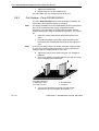
Instrument Setup
Cary system connection diagram (Cary 4000 shown):
1. Instrument
2. IEEE card
3. IEEE-488 cable
4. Plotter
5. Printer
6. Printer cable
2.3.1
Cabling
The monitor, printer/plotter and spectrophotometer are all
connected to the computer via cables that plug into the back of the
computer. Consult your monitor and printer/plotter manuals for
details of their cabling requirements.
The spectrophotometer is connected to the computer by a shielded
IEEE-488 cable. One end of this plugs into the interfacing board in
the computer and the other plugs into the socket at the rear of the
spectrometer.
12 of 32
Publication no. 8510197200, Issue 03, May 2010
Cary 100/300/4000/5000/6000i Hardware Operation Manual
2.3.2
Power
Requirements
Power requirements are detailed in your Cary Pre-installation
manual, and in the Specifications section (refer to section 1.3). You
should read this information thoroughly before connecting the Cary
system to the power supply.
Consult the manuals supplied with your printer and PC for their
power requirements.
Connection
The mains power connection is located at the rear of the
instrument. Before connecting the instrument to the power supply,
ensure both the instrument and the power supply are turned OFF,
and that the voltage selector switches on the instrument rear panel
(Cary 100/300 only) are set to the correct mains power supply
voltage (refer to the table on the rear panel of the instrument).
You should also check the fuses before connecting the instrument
to the mains power supply to make sure they are the correct type
and rating for your location. There are two operator accessible
fuses located at the rear of the instrument. Refer to section 3.3 for
instructions on how to check the fuses.
To connect the instrument to the mains power supply, plug the
mains power cord into the back of the instrument and the free end
of the power cord into the mains power supply, and then switch the
mains power supply on.
2.4
Starting the System
Before turning on the instrument you should ensure:
you have connected the components of the system to one
another, checked the setting of the voltage taps and
connected the equipment to the power supply as described in
section 2.3;
the sample compartment is empty;
the sample compartment lid is closed.
Publication no. 8510197200, Issue 03, May 2010
13 of 32
Cary 100/300/4000/5000/6000i Hardware Operation Manual
Caution
If you have a Cary 300 instrument, you MUST loosen the transit
screw in the wavelength drive before turning the instrument on.
Turning the instrument on without releasing this screw will
damage the instrument. Use a flat-head screwdriver to loosen
the transit screw approximately three turns. (The transit screw is
located at the rear of the instrument, on the right hand side when
viewed from the rear, and is clearly labeled.)
Cary 5000
Switch on the spectrophotometer by depressing the side of the
rocker switch marked ‘⏐’ on the front left hand side of the
instrument.
Note
2.5
For optimum performance, allow your Cary instrument to warm up
for 2 hours before use.
Instrument Performance Tests
The Cary WinUV software has a Validate module, enabling you to
carry out a number of performance tests which check for
conformance to specification for a major subset of instrument
parameters. Many applications are equipped with validation files
that enable you the check that your software has been correctly
installed. Refer to the on-line Help for more information on
validating your software.
If any of the tests fail to meet the specifications you will need to
arrange for a Varian CSR to diagnose and correct the problem.
14 of 32
Publication no. 8510197200, Issue 03, May 2010
Cary 100/300/4000/5000/6000i Hardware Operation Manual
2.6
Sample Holders
This section describes how to install the sample holders in your
instrument. Removal procedures are the reverse unless otherwise
stated.
Before the solid sample or single sample holders can be installed
into the Cary 4000/5000/6000i instruments they must first be
mounted onto the base plate. The base plate is then installed into
the instrument using the new LockDown mechanism, see section
2.7.
2.6.1
Cell Holders—Cary 100/300
The Cary 100/300 comes with a cell holder base and two single
cell holders. These are shipped installed in the sample
compartment. However, if removed they can be re-installed as
follows:
1. Open the sample compartment lid and remove the front
panel.
2. Loosen the two black screws at the back of the sample
compartment and remove the black screw on the front right
hand side. Note the position of the locating pin at the front
left hand side of the sample compartment.
3. Hold the cell holder base so that the black, solid section is
away from you. Note the key holes at the back of the cell
holder base.
4. Carefully place the cell holder base in the sample
compartment and slot the keyholes under the two raised
black screws at the back of the compartment. The front of
the cell holder base should fit over the locating pin.
5. Tighten the raised black screws and also secure the black
screw at the front right hand side of the compartment.
6. Holding a cell holder so that the notched section is to the
right, carefully place the cell holder over the two locating
pins on the cell holder base in the reference beam.
Top view of cell holder with notched section to the right
Publication no. 8510197200, Issue 03, May 2010
15 of 32
Cary 100/300/4000/5000/6000i Hardware Operation Manual
7. Tighten the thumbscrew.
8. Repeat steps 6-7 for the sample beam.
The cell holders are now installed and ready for use.
2.6.2
Cell Holders—Cary 4000/5000/6000i
The Cary 4000/5000/6000i comes with two single cell holders. All
instruments come with base plates as standard.
Note
The single cell holders must be installed onto the base plate before
they can be installed into the sample compartment of the
instrument. For instructions on installing the base plate into the
sample compartment using the LockDown mechanism, see section
2.7.
1. Open the sample compartment lid and remove the front
cover.
Note
2. Place the cell holder base in the sample position on the
base plate. The notched pillar should be on the right hand
side.
If you are operating in normal or double mode the sample position
is at the front of the sample compartment. If you are operating in
reverse mode the sample position is at the rear.
3. Tighten the two locating screws using the 1/8" hexagonal
balldriver.
4. Place a cell holder on the cell holder base (it will only fit one
way) and tighten the thumbscrew.
The cell holder base
1. Adjusting screws
2. Locating screws
3. Notched pillar
4. Locknuts
5. You can now install the base plate into the sample
compartment of the instrument. See section 2.7.
16 of 32
Publication no. 8510197200, Issue 03, May 2010
Cary 100/300/4000/5000/6000i Hardware Operation Manual
6. Once the base plate is installed the cell holder must be
aligned in the light beam. See section 2.6.3.
2.6.3
Aligning the Single Cell Holder
Use this procedure for aligning the cell holders for all instruments.
1. Close the sample compartment lid. In the Cary Win UV
software select the Windows® Start button and then select
Programs, Cary WinUV, Align. Select the Cary tab and
select Zero order in the Instrument Parameters group.
Click Apply.
2. Open the sample compartment lid and place a piece of
white paper in the light path and note where the light beam
strikes the cell holder. The beam should be centered on the
aperture of the cell holder.
Single cell holder aperture, the thatched area in the middle shows
the beam image.
3. If the beam is not centered, use the 2.5 mm hexagonal
balldriver to adjust the three adjusting screws in the cell
holder base until the beam appears to be central to the
aperture. Gently tighten the lock nuts underneath the cell
holder base to fix the height of the adjusting screws.
Publication no. 8510197200, Issue 03, May 2010
17 of 32
Cary 100/300/4000/5000/6000i Hardware Operation Manual
2.6.4
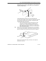
Solid Sample Holder—Cary 4000/5000/6000i
Solid Sample holders installed onto LockDown base plate for Cary
4000/5000/6000i
The Cary 5000/6000i comes with two solid sample holders, which
are optional for the Cary 4000. Each solid sample holder comes
with four solid sample slides of various apertures: standard, 1 mm,
5 mm and
10 mm.
To hold the solid samples, two ‘V’ holders are supplied (one small
and one large). These are held in place on the solid sample slides
by two screws. For delicate samples, a spacer is provided. This is
placed between the V-holder and the solid sample slide. Delicate
samples are then held in place by their edge only.
1
1a
V-holder (1) and spacer (1a) attached to solid sample slide
18 of 32
Publication no. 8510197200, Issue 03, May 2010
Cary 100/300/4000/5000/6000i Hardware Operation Manual
Alternatively, you can attach a locking plate to a solid sample slide
using the two 40 mm pins, as shown below. This arrangement is
suitable for large samples.
2b
2a
2
Solid sample slide (2) with pins (2a) and locking plate (2b)
The solid sample holder must be fitted to the LockDown base plate
prior to being installed into the instrument. To install the solid
sample holder onto the base plate:
Tip
1. Screw the Optical Rails into the removable base, plate
using the 1/8" hexagonal balldriver to tighten the two
locating screws. The notch should be on the right hand
side. (Two post clips on the underside of the plate identify
the back of the base plate.)
Some users may find it more convenient to have a set of optical
rails and solid sample holders, permanently installed onto a base
plate and simply install and remove the base plate as required.
3a
3b
3c
Optical rails showing the locating screw (3a), notch (3b) and
adjustment screw (3c)
Publication no. 8510197200, Issue 03, May 2010
19 of 32
Cary 100/300/4000/5000/6000i Hardware Operation Manual
Note
2. Place the other set of rails in the reference position with the
notch towards the left side of the base plate. The setup
procedure for both sample and reference solid sample
holders is otherwise the same.
If you are operating in normal or double mode the reference
position is at the rear of the sample compartment. If you are
operating in reverse mode the reference position is at the front.
3. Loosely clamp the slide holder to its base. Insert the slide
holder onto the optical rails but do not tighten the clamping
screw.
4a
4b
Slide holder showing the side screw (4a) and clamping screw (4b)
Tip
4. Insert the solid sample slide with attached V holder or
locking plate into the centre of the slide holder and tighten
the side screw.
It is recommended that you place the solid sample slide into the
slide holder so that the slide masks the light beam before it
reaches the sample. This minimizes scattering of the light beam.
5. You must now install the base plate into the sample
compartment. See section 2.7 and then align the
accessory, see section 2.6.5.
20 of 32
Publication no. 8510197200, Issue 03, May 2010
Cary 100/300/4000/5000/6000i Hardware Operation Manual
2.6.5
Aligning the Solid Sample Holder
Use this procedure for aligning the solid cell holders.
1. Close the sample compartment lid. In the Cary Win UV
software set the wavelength to 0 nm (zero order) by
selecting the Windows® Start button and then Programs,
Cary WinUV, Align. Select the Cary tab and select Zero
order in the Instrument Parameters group. Select Apply.
2. Place a piece of white paper in the light path and note
where the light beam strikes the solid sample slide. The
beam should be centered on the aperture.
3. If the beam is not centered, align it by first moving the slide
holder along the optical rails to the centre of the sample
compartment. Tighten the clamping screw on the slide
holder. You will then need to use the 2.5 mm hexagonal
balldriver to adjust the three adjusting screws on the optical
rail base until the beam appears to be visually aligned.
Once you have done this, the solid sample holder is aligned and
ready for use.
Note
You can use a polarizer/depolarizer with the solid sample holder.
These are available from Varian (part number 02 101316 00/02
101317 00).
Extra slide holders are also available (part number 58 100054 00).
Two of these can be screwed into the ends of the optical rails.
If you want to use liquid rather than solid samples with your Cary
instrument, you will first need to purchase a cell holder base (part
number 00 100481 00) and a single cell holder (part number 01
102601 90) from Varian.
Alternatively, you can buy a variable path length cell holder
available from Varian (part number 02 101253 00 for 50 mm or part
number 66 100140 00 for 100 mm). This will slot into your solid
sample holder base. Refer to the figure below.
Publication no. 8510197200, Issue 03, May 2010
21 of 32
Cary 100/300/4000/5000/6000i Hardware Operation Manual
Optional accessories for the Solid Sample Holder:
Variable path length cell holder (left) Side mounted slide (right)
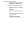
Position the sample so that the centre of the sample sits in the
centre of the sample compartment (as shown below). The sample
should be centered both horizontally and vertically.
Aligning the sample in the sample compartment. The picture on the
left shows the sample compartment from above, the dotted line
indicates the middle of the compartment. The picture on the right
shows the middle of the sample compartment when viewed from
the side.
22 of 32
Publication no. 8510197200, Issue 03, May 2010
Cary 100/300/4000/5000/6000i Hardware Operation Manual
2.7
Installing the Base Plate Using the LockDown
Mechanism
The base plate needs to be locked into position in the sample
compartment.
1. The LockDown mechanism features two posts at the back
of the base plate and a clamp post at the front of the plate.
Hold the base plate by the handle (with accessory), so that
the posts are situated at the rear of the sample
compartment.
2. Load the base plate into the sample compartment by
pushing it rearwards, allowing the two rear-mounted posts
to engage under the clamps in the sample compartment
floor.
3. Lower the front edge of the base plate so that the front post
engages in the lockdown.
4. Move the lever at the front of the sample compartment to
the left to lock the base plate into position.
5. You now need to align the accessory. See section 2.6.5.
2.8
Installing Other Accessories
Your Cary instruments are compatible with a wide range of
accessories. In the online Help there are descriptions of the
accessories as well as instructions for installing them. Many of the
installation instructions are available as a .PDF file for easy printing
out from the Help.
2.9
2.9.1
Nitrogen Purging
Nitrogen Purging System—Cary 4000/5000/6000i
The nitrogen purging system is NOT supplied by Varian, but the
following items are available from appropriate commercial
suppliers:
1.
Nitrogen
Ultra-high purity liquid nitrogen, for example Nitrogen 5.0, (in
conjunction with a heat exchanger) is recommended because it is
less expensive than compressed nitrogen and is usually of better
quality. If compressed nitrogen must be used, the gas must be dry,
oil-free and uncontaminated. Never use compressed nitrogen from
Publication no. 8510197200, Issue 03, May 2010
23 of 32
Cary 100/300/4000/5000/6000i Hardware Operation Manual
a supplier who uses oil or water in the compression process. Such
processes invariably leave fine particles of oil suspended in the
nitrogen, which will form an oily deposit on optical surfaces. Use
nitrogen from a supplier who fills containers from immersion pumps
lubricated with liquid nitrogen.
Note
The instrument warranty will be void if damage is caused by the
use of unsatisfactory nitrogen.
2.
Pressure regulator and gauge
Operating pressure is from 83 to 172 kPa (12 to 25 psig). Always
use an appropriate regulator and gauge to ensure that the nitrogen
supply is consistently maintained at the correct pressure.
3.
Supply tubing
Use clean, flexible plastic tubing 6 mm (1/4 inch) inside diameter
(Tygon PVC or equivalent). Never use rubber tubing because it
may be treated internally with talc that can be blown into the optical
system.
4.
Gas manifold
The manifold should be fitted with one inlet suitable for connection
to the nitrogen supply system and two outlets suitable for
connection to the spectrophotometer.
5.
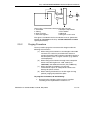
Flowmeter
Two flowmeters (complete with control valves) should be inserted
in the system between the manifold outlets and the
spectrophotometer (refer to diagram). Each flowmeter should be
capable of monitoring flow rates between 0 and 30 litres per minute
(64 cubic feet per hour).
24 of 32
Publication no. 8510197200, Issue 03, May 2010
Cary 100/300/4000/5000/6000i Hardware Operation Manual
The position of flowmeters when purging with nitrogen:
1. Instrument
2. Sample compartment
3. Tubing
4. Flow meters
5. Shut-off valves
6. Manifold
7. Pressure regulator
8. Nitrogen control valve
This figure is included in the Pre-Installation manual, (publication
number 85 101280 00 for the Cary 100/300/4000/5000 and 6000i
spectrophotometers).
2.9.2
Purging Procedure
You may need to purge the instrument with nitrogen under the
following circumstances:
(a)
When taking measurements at wavelengths below 200
nm where it is necessary to minimize the effects of
oxygen absorption bands and other absorbing species in
the atmosphere such as organic solvents (e.g. acetone
and isopropanol).
(b)
When taking measurements through water-absorption
bands in the NIR region near 1370, 1850 (Cary
5000/6000i) and 2580 and 2750 nm (Cary 5000 only).
(c)
When operational conditions are such that
environmental vapors or solid particles could cause
damage to optical surfaces.
(d)
When working continuously in the UV region for long
periods, purging will protect the optics.
To purge the instrument, do the following:
1. Ensure that the nitrogen purging system is installed
according to the requirements in section 2.9.1.
Publication no. 8510197200, Issue 03, May 2010
25 of 32
Cary 100/300/4000/5000/6000i Hardware Operation Manual
2. Open the nitrogen control valve and then adjust the
regulator to provide a supply pressure between 83 and 172
kPa (12–25 psig).
3. Set the flowmeter valves to give the following flow rates:
Instrument
0-20 L/min
Sample compartment
0-10 L/min
Note
(i) If samples are changed frequently, you may need to increase
the flow rate through the sample compartment.
(ii) You can gauge the success of purging by scanning for oxygen
in the UV-Vis region and by scanning for water vapor in the NIR
region (Cary 5000/6000i only).
2.9.3
Nitrogen Purging—Cary 100/300
The sample compartment of the Cary 100/300 can be nitrogen
purged if the Extended Sample Compartment is fitted. The nitrogen
supply should be attached to the inlet tubes beneath the Extended
Sample Compartment.
Refer to the Extended Sample Compartment operating instructions
in the online Help for further information.
2.10
2.10.1
Sample Compartment Base Removal
Cary 100/300
The Cary 100/300 has a rectangular base plate in the sample
compartment to protect the connectors from spills. You will need to
remove this plate when you install an accessory that plugs into one
of the sockets underneath the sample compartment.
The plate should be replaced in the sample compartment when the
accessory is removed to prevent damage to the connectors from
liquid spillage.
2.10.2
Cary 4000/5000/6000i
The base of the Cary 4000/5000/6000i sample compartment is
completely removable. This allows for large apparatus to be
positioned in the sample compartment.
26 of 32
Publication no. 8510197200, Issue 03, May 2010
Cary 100/300/4000/5000/6000i Hardware Operation Manual
Note
Once the floor of the sample compartment has been removed, the
optical alignment with respect to the floor has been lost. Before
performing any microcell analyses you will need to realign the
optics.
To remove the base, follow the steps described below:
1. Remove the front door.
2. Remove the cover plate between the floor and the
horizontal extrusion.
3. Remove the horizontal extrusion by unscrewing the 2
screws in its base.
4. Remove the lower cover plate.
5. Undo the fasteners holding the sample compartment floor.
6. Remove the sample compartment floor, the lock down
mechanism will also be removed.
Publication no. 8510197200, Issue 03, May 2010
27 of 32
Cary 100/300/4000/5000/6000i Hardware Operation Manual
This page is intentionally left blank.
28 of 32
Publication no. 8510197200, Issue 03, May 2010
Cary 100/300/4000/5000/6000i Hardware Operation Manual
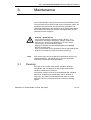
3.
Maintenance
This chapter includes some of the maintenance procedures for the
Cary instrument that may be carried out by an operator. Others are
included in the on-line help. Any maintenance procedures not
specifically mentioned in this chapter or in the on-line help should
be carried out only by Varian-trained, Varian-qualified or Varianauthorized service engineers.
Warning – Shock Hazard
This instrument contains electrical circuits, devices, and
components operating at dangerous voltages. Contact with
these circuits, devices and components can cause death,
serious injury, or painful electrical shock.
Operators and other unauthorized personnel must NEVER
remove the main cover.
Only Varian-trained, Varian-qualified, or Varian-approved service
engineers may open the main cover of the instrument.
Note
3.1
This section refers only to maintenance procedures for the Cary
spectrophotometer. You should refer to your PC and printer
manuals for their maintenance procedures.
Cleaning
Any spills in the sample compartment should be wiped up
immediately and any deposits on the sample compartment
windows should also be removed.
The exterior surfaces of the Cary spectrophotometer should be
kept clean. All cleaning should be done with a soft cloth. If
necessary, this cloth can be dampened with water or a mild
detergent. Do not use organic solvents or abrasive cleaning
agents.
Publication no. 8510197200, Issue 03, May 2010
29 of 32
Cary 100/300/4000/5000/6000i Hardware Operation Manual
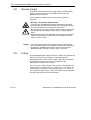
3.2
Source Lamps
Instructions for how to change and align both the visible and UV
lamps for Cary instruments are included in the online Help
provided with the software.
For both lamps the following safety precautions should be
observed:
Warning – Hot Surface, Shock Hazard
Lamp surfaces and mounting brackets will become hot during
operation and will remain hot for some time after being switched
off. The temperatures are sufficient to cause burns.
The UV and mercury lamps operate at high voltage. Contact with
this voltage can cause death, serious injury, or painful electric
shock.
Before changing either the deuterium or visible lamps, ALWAYS
switch the instrument off, remove the power supply cable and
allow the lamps to cool.
Caution
3.3
Care must also be taken when removing lamps. Touching the
glass envelope of either the deuterium or visible lamp will reduce
its efficiency. NEVER touch the glass surfaces of new lamps.
ALWAYS handle a lamp by its base, using a soft cloth.
Fuses
The spectrophotometer contains two fuses which are located at the
back of the instrument. To replace a fuse, disconnect the
spectrophotometer from the power supply, and replace the blown
fuse with one of the type and rating as indicated in the
Specifications section of this manual.
The fuses have a code marked on the cap (e.g. T 2AH250V). This
refers to the fuse characteristic (‘T’ - time lag, ‘F’ - fast acting), the
current rating (‘x’ amperes), the breaking capacity (‘H’ - heavy, ‘L’ low) and the voltage rating (‘y’ volts). This code must correspond to
the code appearing next to the fuseholders.
30 of 32
Publication no. 8510197200, Issue 03, May 2010
Cary 100/300/4000/5000/6000i Hardware Operation Manual
Warning – Shock Hazard, Fire Hazard
To prevent reduced safety protection or unwanted fusing,
ALWAYS ensure that the code on the fuse cap matches the
information printed next to the fuseholders.
To check a fuse:
1. Disconnect the instrument from the mains power supply.
2. Undo the fuse cap by pressing the cap and turning it
counter-clockwise.
3. Pull the cap out carefully. The fuse should be held in the
fuse cap.
4. Check that the fuse is the correct type and is not damaged.
If necessary, replace the fuse.
5. Place the fuse into the cap, push the cap in, and then turn
the cap clockwise.
Note
6. Reconnect the instrument to the mains power supply.
If a fuse blows repeatedly, it may indicate other problems with the
Cary instrument. A service call may be required.
Publication no. 8510197200, Issue 03, May 2010
31 of 32
Cary 100/300/4000/5000/6000i Hardware Operation Manual
3.4
Spare Parts
Instrument spares for Cary 100/300 instruments
Item
Part Number
PCI-GPIB National Instruments card. Supplied
9910102100
as standard.
Controller GPIB USB
7910051600
Instrument fuse*, 4amp time lag,
1910008900
ceramic/5x20mm
Instrument fuse*, 5 amp time lag, ceramic/M205 1910009100
Thumbscrew kit: Includes all thumbscrews for
9910064100
instrument and accessory
9910064300
Spares kit: Includes: Accessory locating pin,
Accessory fastening screws (rear), Instrument
feet (plastic), Instrument cover snap cap
washer, Snap cap, ACB cover plate, socket
covers for ACB
Visible QI lamp
5610021700
Deuterium lamp
5610021800
*Refer to the information printed on the back of the instrument to
determine which fuse types you need.
Instrument spares for Cary 4000, 5000 and 6000i instruments
Item
Instrument fuse
T2AH250V for 240v operation
Instrument fuse
T2.5AH250V for 110v operation
VIS lamp
Deuterium lamp
Mercury lamp
PCI-GPIB card
Controller GPIB USB
Part Number
1910009400
1910009500
5610013900
0110713990
5610136300
9910102100
7910051600
For further information regarding spare parts and their part
numbers please refer to the Varian, Inc website found at:
http://www.varianinc.com.
32 of 32
Publication no. 8510197200, Issue 03, May 2010