1
PHILIPS
I Philips Medical Systems
parts list
Philips Medical Systems Nederland B.V. I Technical Service I Best
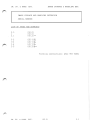
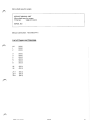
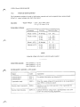
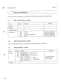
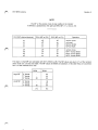
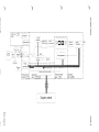
SERVICE PARTSLIST UNIT
PEI: 9807 603 60001
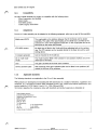
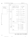
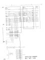
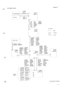
DESCRIPTION: CASSETTEHOLDER BV29
SERIAL NR:
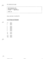
List of pages and drawings
P-00
(91.0)
P- 1
(91.0)
PZ-1
(91.0)
*printing instructions 4522 983 32271
9807 603 60001
(91_01
P-nn
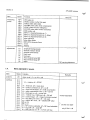
Cassetteholder 8V29
!SCHEME/
!PAGE
I
1PZ1PZIPZ1PZIPZ1PZIPZIPZ1PZ:PZ-
1
1
1
1
1
1
1
1
1
1
:PZ- 1
.
Section P
:INDEX
I
1CODENUMBER
'.
1
.
I
:DESCRIPTION
I
:
..
,
.
1
: a
I
I
1
1
1
b
c
d
e
f
1 g
I h
1 j
1 k
1 1
12622
14522
14522
12622
14522
14522
14522
14522
14522
2622
115
128
103
115
128
128
128
128
128
115
4522 128
..
.
.
.
.
.
.
,
.
.
.
.
.
.
.
.
,
.
.
.
,
:
.
i
.
.
:tension spring
lend stop
cap
Belleville washer
:fastener
:cap nut
housing
shaft
knob
:compression spring
clamping ring assy
I
.
.
.
.
.
.
.''
1
1
I2x
I2x
..
I28x
:
1
.
t
.
n
.
.
I
1
,
,
.
i
1
..
.
.
1
.
1
1
.
:
.
.,
.
.
.
.
00255
10051
87461
10002
10152
10062
10022
10032
10071
02372
10161
DATA
,
.
,
.
.
1
,
.
.
.
.
:
;
,.
.
,
:
.
..
..
.
,
:
.
:
:
,.
,.
:
;
..
.
.
.
.
.
..
,
..
.
;
1
.
.
.
.
1
..
1
1
,
.,
,
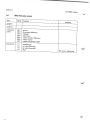
BV29
PEI MANUALS
SERVICE PEI MANUALS
BV29 SYSTEM
MODULE CODE NUMBER
4522 983 52213
LIST OF PAGES AND DRAWINGS
(b/93.1)
(92.0)
(92.0)
(b/93.1)
een
BV29/PEI
(b/93.1)
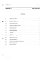
2.1
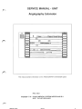
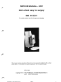
SERVICE MANUAL - UNIT
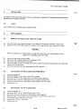
Image Storage & Handling Extension
.-.
J5
•
i' §§§
. ..
- 0
.4
S'
I
00,
:
!888, t=i
i>
I
"
m ri (R. Feinsdillvipifri7). IF-ew ii
F->i
r
61
1E
r-- - - ----.: PIR5-1
-,-
' ai ‘'
—•
tu—...„
r"----1
1
1
e>
:
::::,-
r/
P8
F-1
rq
14)\
r"-1
1)- I _ _ _ _
DISKINTERFACE
POSTPROCESSING
, .,./ -4-1'
r
,
--.3-
11--
1, /—.....
-
4'3
v.
I.:
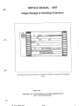
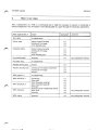
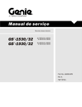
This manual contains information on the IMAGE STORAGE & HANDLING EXTENSION
option.
IPSC: Best
Copyright © '92 PHILIPS MEDICAL SYSTEMS NEDERLAND B.V.
BEST THE NETHERLANDS
IM RT
R.
HAND FXT
(92.01
1
IM. ST . & HAND. EXT. IMAGE STORAGE & HANDLING EXT.
IMAGE STORAGE AND HANDLING EXTENSION
SERIAL NUMBER:
LIST OF PAGES AND DRAWINGS
P`
0.5
1 2.1
(92.0)
(92.0)
(92.2)**
1-1
1-2
1-3
1-4
1-5
(92.1)E*
(92.1)E*
(92.1)E*
(92.1)E*
(92.2)E**
Printing instructions: 4522 983 52601
IM. ST . & HAND. EXT. (92.2)
2.1
Section IM. ST . & HAND. EXT.
BV29/BV26
Section :
IMAGE STORAGE & HANDLING EXT.
Contents
e""
rk
INTRODUCTION 1-2
ITEMS SUPPLIED 1-2
COMPATIBILITY 1-2
INSTALLATION 1-3
4.1.
MEMORY BOX UNIT TROLLEY 1-3
4.2.
DISK INTERFACE BOARD P7 AND POSTPROCESSING BOARD P8 1-4
4.3.
HARD DISK (WF) 1-4
SETTING TO WORK 1-5
CHECKING THE FUNCTIONS 1-5
Section IM. ST . & HAND. EXT.
1.
INTRODUCTION
The IMAGE
Storage
Mosaic
- Zoom
Measure
STORAGE AND HANDLING EXTENSION offers the following functions:
: 190 images on hard disk.
: displaying of 16 images from hard disk simultanuously.
: increasing the area of intrest.
indicating the relative difference in vessel diameter of two selected cross sections.
2.
ITEMS SUPPLIED
BV29/BV26
The following items are part of the delivery:
- NEC 3.5-in. Disk Drive.
- Digital Scopof ix MMP Diskinterface board P7.
- Digital Scopof ix MMP Postprocessing board P8.
- Cabling for connection between:
WFX2 - WHDP7J1 (flatcable)
WFX1 - WHDP7J2 (four wire cable)
- Mounting material for Hard Disk:
( a mounting plate, 4 screws M4 with 4 spring washers, 4 screws M3 with 4 rivets and 4 spring washers and
4 ty-raps.)
3.
COMPATIBILITY
The IMAGE STORAGE & HANDLING EXTENSION is compatible with:
MMC 1102 (BV29)
MMC 1151 (BV26)
Section IM. ST . & HAND. EXT.
BV29/BV26
11"
4.
INSTALLATION
4.1.
MEMORY BOX UNIT TROLLEY
For pulling out the complete Memory Box Unit (MBU) do:
Procedure BV26:
Remove covers located at both sides of the trolley-keyboard (4 screws each side).
- Pull out the MBU half way.
Disconnect the connectors WTX1 + earth, WTX3, WTX2 and WTX4 to prevent damaging of the cables.
- Position the cables so that they can't be damaged when the MBU is pulled out completely.
- Pull out the Memory Box Unit completely ( Unit is secured by blocking screws).
Remove the EMC-plate at the left side of the MBU by removing the 20 screws.
Remove the 2 PCB holding-plates ( 4 screws).
- Remove the blocking screw at the left side, so that the MBU can be pulled out a little bit more to have better
access to loosen the EMC-plate covering the location for the Hard Disk.
NOTE
REMOVE THE SCREWS CAREFULLY.
Remove the EMC-plate covering the location of the Hard Disk (12 screws).
Procedure BV29:
- Remove covers located at both sides of the trolley-keyboard (4 screws each side).
Pull out the Memory Box Unit completely ( Unit is secured by blocking screws).
- Remove the EMC-plate at the left side of the MBU by removing the 20 screws.
- Remove the 2 PCB holding-plates ( 4 screws).
- Remove the blocking screw at the left side, so that the MBU can be pulled out a little bit more to have better
access to loosen the EMC-plate covering the location for the Hard Disk.
NOTE
REMOVE THE SCREWS CAREFULLY.
- Remove the EMC-plate covering the location of the Hard Disk (12 screws).
Section IM. ST . & HAND. EXT.
4.2.
BV29/BV26
DISK INTERFACE BOARD P7 AND POSTPROCESSING BOARD P8
NOTE
USE ELECTROSTATIC DISCHARGE BRACELET WHEN PUTTING IN THE BOARDS
Procedure:
- Put DISKINTERFACE BOARD on postion P7.
- Put POSTPROCESSING BOARD on position P8.
4.3.
HARD DISK (WF)
Procedure:
- Mount the HARDDISK on the mounting plate with 4 screws M3, 4 rivets and 4 spring washers.
NOTE
BEFORE MOUNTING THE HARDDISK MAKE SURE THAT THE INSERTS IN THE 4 VIBRATION DAMPERS
ARE CLEAR (NO RUBBER).
THE HARDDISK FLATCABLE CONNECTOR MUST BE LOCATED AT THE LEFT SIDE
- Mount the HARDDISK with mounting plate on the 4 vibration dampers.
Use the delivered mounting material (4 screws M4 and 4 spring washers).
- Connect cables:
. WFX1 - WHDP7-J2 ( four wire cable )
. WFX2 - WHDP7-J1 ( flat cable )
- Remount the PCB holding plates, both EMC-plates, blocking screw and covers.
Section IM. ST . & HAND. EXT.
BV29/BV26
SETTING TO WORK
5.
- Leave the MMP-unit open.
- Enter the SERVICE MENU.
- Select the MBC UTIL & FREQUENCY menu (line 40).
Set CHANGE MODE in order to change current settings.
Put jumper WT2 : S1-5 in position on.
Select line 43 (Format disk).
Press <ACC> .
Give "Y".
Wait until refreshed menu appears (after 5 sec).
Text in lower left corner: "FORMATTING DISK"
Service menu appears after the DISK is formatted.
RETURN TO MAIN MENU.
EXIT SERVICE MENU.
Leave CHANGE MODE.
- Put jumper WT2 : S1-5 in position "OFF".
- Push back MMP-unit.
- Tighten the four screws wich holds the MMP-unit.
6.
CHECKING THE FUNCTIONS
Check the functions of the IMAGE STORAGE & HANDLING EXTENSION:
SEE THE USER's MANUAL.
ILA CT D LJAAIrl
PVT
(92.21E
1-5
SERVICE MANUAL - UNIT
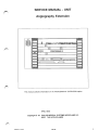
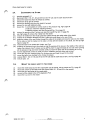
Angiography Extension
J5
§§§
888
,i
(
le
RT.1) e 15.
'Ma
MI
.11
p.i 1 .-i 5- 1
. ,,.. ,
rnri ..: ," .1.fraT1R-Tif:3---n
e .1.
IT-
-
1.--<-fl
(..
.
,..,_...,,3
PROCESSING 2
pi
,...., , .
1=-1 RTI F-1
•
/*1 _ _
l eA
ti
IF777
2 II
1t''''r.,nnn
•'.'.•^1-,•
-- r;
• -Iv) I . '
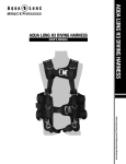
This manual contains information on the ANGIOGRAPHY EXTENSION option.
IPSC: Best
Copyright © '92 PHILIPS MEDICAL SYSTEMS NEDERLAND B.V.
BEST THE NETHERLANDS
Aninin FYT
(92 01
1
BV29/BV26
ANGIO. EXT.
ANGIOGRAPHY EXTENSION
SERIAL NUMBER:
)
LIST OF PAGES AND DRAWINGS
0.5
1
2.1
(92.0)
(92.0)
(92.1)*
1-1
1-2
1-3
(92.0)E
(92.1)E*
(92.1)E*
Printing instructions: 4522 983 52611
ANC,TO. EXT.
(92.1)
2.1
BV29/BV26
Section ANGIO. EXT.
Section :
ANGIOGRAPHY EXT.
Contents
INTRODUCTION 1-2
ITEMS SUPPLIED 1-2
COMPATIBILITY 1-2
INSTALLATION 1-3
SETTING TO WORK 1-3
CHECKING THE FUNCTIONS 1-3
Section IM. ST . & HAND. EXT.
1.
BV29/BV26
INTRODUCTION
The IMAGE STORAGE AND HANDLING EXTENSION offers the following functions:
Storage
: 190 images on hard disk.
- Mosaic
: displaying of 16 images from hard disk simultanuously.
Zoom
: increasing the area of intrest.
- Measure : indicating the relative difference in vessel diameter of two selected cross sections.
2.
ITEMS SUPPLIED
The following items are part of the delivery:
- NEC 3.5-in. Disk Drive.
- Digital Scopof ix MMP Diskintertace board P7.
Digital Scopof ix MMP Postprocessing board P8.
- Cabling for connection between:
WFX2 - WHDP7J1 (flatcable)
WFX1 - WHDP7J2 (four wire cable)
Mounting material for Hard Disk:
( a mounting plate, 4 screws M4 with 4 spring washers, 4 screws M3 with
4 ty-raps.)
3.
COMPATIBILITY
The IMAGE STORAGE & HANDLING EXTENSION is compatible with:
MMC 1102 (BV29)
MMC 1151 (BV26)
4 rivets and 4 spring washers and
Section ANGIO. EXT.
BV29/BV26
4.
INSTALLATION
Procedure BV26:
Remove covers located at both sides of the trolley-keyboard ( 4 screws each side).
Pull out the Memory Box Unit (MBU) half way.
- Disconnect the connectors WTX1 + earth, WTX3, WTX2 and WTX4 to prevent damaging the cables.
- Position the cables so that they can't be damaged when the MBU is pulled out completely.
- Pull out MBU completely ( unit is secured by blocking screws).
- Remove the EMC-plate at the left side of the MBU by removing 20 screws.
- Remove the 2 PCB holding-plates (4 screws).
- Remove the -dummy- PROCESSING 2 BOARD on position P3.
Place the PROCESSING 2 BOARD on position P3.
Exchange the footswitch with the delivered footswitch.
Reassemble in reverse order.
.01"6.
Procedure BV29:
- Remove covers located at both sides of the trolley-keyboard ( 4 screws each side).
- Pull out MBU completely ( unit is secured by blocking screws).
- Remove the EMC-plate at the left side of the MBU by removing 20 screws.
- Remove the 2 PCB holding-plates (4 screws).
Remove the -dummy- PROCESSING 2 BOARD on position P3.
- Place the PROCESSING 2 BOARD on position P3.
- Exchange the footswitch with the delivered footswitch.
- Reassemble in reverse order.
SETTING TO WORK
5.
NOTE
NO SETTING TO WORK INSTRUCTIONS HAVE TO BE CARRIED OUT AFTER INSTALLATION OF
THIS OPTION.
6.
CHECKING THE FUNCTIONS
Check the functions of the ANGIOGRAPHY EXTENSION:
SEE THE USER's MANUAL.
Anirtin F YT
MP 11F
1-3
SERVICE MANUAL - UNIT
2--
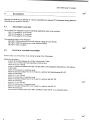
Video Memory Extension for KrImages
4
J5
I
("D
e If.
Mir!
mr—i eve .4, Rili FilFilMFiF10
—
t 1
-..'''
VD1 MEMORY EXTE
NSION
P
r-=1 T:1 F-1
t..
- .
1- \
11
32
/q,1 _ _
F- i—
1.- . -
I
II__
[
s IA
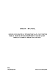
This manual contains information on the VIDEO MEMORY EXTENSION FOR 32
IMAGES option.
IPSC: Best
Copyright © '92 PHILIPS MEDICAL SYSTEMS NEDERLAND B.V.
BEST THE NETHERLANDS
r's
RArRA rYT 'I/ IRA
(92_ m
1
BV29/BV26
VID. MEM. EXT. 32 IM.
VIDEO MEMORY EXTENSION FOR,,032IMAGES
SERIAL NUMBER: // 3 zcz 0 c
LIST OF PAGES AND DRAWINGS
2.1
(92.0)
(92.0)
(92.1)*
1-1
1-2
1-3
(92.0)E
(92.1)E*
(92.1)E*
0.5
1
Printing instructions: 4522 983 52621
/7,vm
T-ruf
/ 0') 1 1
1
Section VID. MEM. EXT. 32 IM.
BV29/BV26
VIDEO MEMORY EXTENSION FOR 32 IMAGES
Contents
INTRODUCTION 1-2
ITEMS SUPPLIED 1-2
COMPATIBILITY 1-2
INSTALLATION 1-3
SETTING TO WORK 1-3
CHECKING THE FUNCTIONS 1-3
Section VID. MEM. EXT. 32 IM. 1.
INTRODUCTION
The VIDEO MEMORY EXTENSION FOR 32 IMAGES offers the following functions:
- 32 image video memory for cine display.
Replay last FLUORO scene.
Selectable acquisition frame speed.
Cine loop editing.
2.
ITEMS SUPPLIED
The following item is part of the delivery:
- Digital Scopofix MMP CINE MEMORY BOARD P5.
3.
COMPATIBILITY
The VIDEO MEMORY EXTENSION FOR 32 IMAGES is compatible with:
MMC 1102 (BV29)
MMC 1151 (BV26)
BV29/BV26
Section VID. MEM. EXT. 32 IM.
BV29/BV26
4.
INSTALLATION
Procedure BV26:
Remove covers located at both sides of the trolley-keyboard ( 4 screws each side).
- Pull out the Memory Box Unit (MBU) half way.
- Disconnect the connectors WTX1 + earth, WTX3, WTX2 and WTX4 to prevent damaging the cables.
Position the cables so that they can't be damaged when the MBU is pulled out completely.
- Pull out MBU completely ( unit is secured by blocking screws).
- Remove the EMC-plate at the left side of the MBU by removing 20 screws.
- Remove the 2 PCB holding-plates (4 screws).
Place the CINE MEMORY BOARD on position P5.
- Reassemble in reverse order.
Procedure BV29:
Remove covers located at both sides of the trolley-keyboard ( 4 screws each side).
Pull out MBU completely ( unit is secured by blocking screws).
- Remove the EMC-plate at the left side of the MBU by removing 20 screws.
- Remove the 2 PCB holding-plates (4 screws).
- Place the CINE MEMORY BOARD on position P5.
- Reassemble in reverse order.
5.
SETTING TO WORK
NOTE
NO SETTING TO WORK INSTRUCTIONS HAVE TO BE CARRIED OUT AFTER INSTALLATION OF
THIS OPTION.
6.
CHECKING THE FUNCTIONS
Check the functions of the VIDEO MEMORY EXTENSION FOR 32 IMAGES:
SEE THE USER's MANUAL.
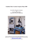
SERVICE MANUAL - UNIT
23cm shield assy for surgery
9896 010 02311
For serial numbers, see list of pages and drawings
This manual contains descriptive information on the equipment identified by the number
stated above. For information on specific application, see the system manual.
IPSC: Best
Copyright © '93 PHILIPS MEDICAL SYSTEMS NEDERLAND B.V.
BEST THE NETHERLANDS
DAM-earl in The. Kles+hcsrlftrsric
fag
n%
1
23cm shield assy for surgery
SERVICE MANUAL-UNIT
23cm shield assy for surgery
: 9896 010 02311
TYPE NO.
SERIAL NO.
Manual codenumber : 4522 983 54411
List of Pages and Drawings
0.5
1
2
(93.0)
(93.0)
(93.0)
3
4
5
6
7
8
(93.0)
(93.0)
(93.0)
(93.0)
(93.0)
(93.0)
25
26
(93.0)
(93.0)
Z1-1
Z2-1
Z3-1
(93.0)
(93.0)
(93.0)
nonce ni n
CIOQ-11
23cm shield assy for surgery
Contents
1.
Introduction and technical data 4
1.1.
Purpose 4
1.2.
Items supplied 4
1.3.
Equipment identification 4
1.4.
1.4.1.
1.4.2.
1.4.3.
1.4.4.
1.4.5.
Technical data Dimensions and weights Protections Compatibility Adaptations Applicable standards 4
4
4
5
5
5
2.
Installation 6
2.1.
Tools 6
3.
Replacements 6
3.1.
Remove the shield assy from the stand 6
3.2.
Exchanging the II/TV adaptation PCB (BA1) 6
3.3.
Exchanging the HT II-generator 6
3.4.
Exchanging the II-tube 7
3.5.
Mount the shield assy to the stand 4.
Adjustments 8
4.1.
Adjustment facilities 8
4.2.
Electrical focusing adjustment 8
7
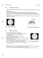
ILLUSTRATIONS AND DRAWINGS
25
Equipment identification Illustrations for replacement procedures I nterface diagram Cabling BV29 II/TV adaptation 0610g
ni n
fl'3"4-11
26
Z1 -1
Z1 -2
Z1-3
(AR m
3
23cm shield assy for surgery
1.
INTRODUCTION AND TECHNICAL DATA
1.1.
PURPOSE
This 23 cm II tube assembly is applied in the BV29 system. The shield has been designed for housing; a 23cm
II-tube, a basic lens, an XTV-8SRI camera, an adaptation board and an II-generator in the II side box.
1.2.
ITEMS SUPPLIED
The numbers in the list refer to the items in figure (a) on page 25.
shield with side box
camera cover
couple-plate
hand-grip (2x)
5.
6.
7.
8.
pressure ring
finishing ring with implosion plate, p.-metal ring + lead ring
vibration dampers
BV29 II/TV adaptation board BA1
In plastic bag:
4 screws M4 x 10 for mounting a grid on the finishing ring.
-
4 identification plates, see info at para. 1.3.
cabling set (6 cables) as shown on drawing Z2-1.
1.3.
EQUIPMENT IDENTIFICATION
The identification plates are located on the central labelling station of the system and on the inner side of the
camera cover as indicated on page 25. Included are the following plates:
Name and Address plate. Type number plate with serial number of the 23 cm II tube assy
Manufacturer plate.
HHS certification label.
HHS date of manufacture.
UUCSA classification mark.
NOTE
In case of replacement of certifiable items always replace duplicate label on the inside of the camera cap
and on the central labelling station "i" of the BV29.
1.4.
TECHNICAL DATA
1.4.1.
Dimensions and weights
Overall dimensions: see drawing Z9-1, total weight: - 200 N = - 20 kg.
1.4.2.
4
Protections
X-Rays
The shield, camera cover and other relevant parts are provide with a lead lining to
protect the environment against radiation of x-ray beams which are projected
perpendicular to the entrance screen
Magnetic shielding
The shield is provided with .t-metal to minimize the effect of weak alternating or static
magnetic fields inside the container. All parts of the shield are made of non-magnetic
material.
Mechanical
In case the II tube implodes, an implosion plate protects the environment against
fragments of the tube.
(93.01
9R9R ni n 02:111
23cm shield assy for surgery
1.4.3.
Compatibility
The 23cm shield assembly for surgery is compatible with the following items:
23cm II-generator non blanking
23cm II-tube
XTV-8SRI camera
mobile surgery stand BV29
1.4.4.
Adaptations
The 23 cm II tube assembly can be adapted to the following equipment, which are no part of this assembly:
Mobile stand BV29
The couple-plate is the interface between the BV 29 Stand and the shield
assembly. The cable of the stand leading to the shield has to be fitted to the
connector X1 of the II/TV adaptaion board BA1 on the couple-plate and to the
earth point on the cable relief bracket.
XTV-8SRI camera
the basic lens is fitted to the II-tube with three adjusting bolts in the centring
ring. The XTV camera can be mounted directly to the basic lens with a quick
locking device.
II compact generator
Can be mounted in the II side box.
23 cm multi mode
II-tube
The II-tube must be fitted in the container in one position (markers are on the
shield and on the tube).
Grid
The grid is screwed to the front of the container.
Service phantom plate
After removing of the grid a phantom plate can be fitted in two positions (90°
rotated) to the front of the container.
1.4.5.
Applicable standards
The following standards are applicable to the 23 cm II tube assembly.
PMS products are developed and manufactured with observance of a number of directives, regulations and
standards. (e.g. International product safety standards as IEC, ISO, CISPR and national performance and
product safety as 21CFR Subch. H and J, U.L., CSA, DIN and VDE.)
Information regarding the compliance status with standards and product approvals is obtainable at:
Philips Medical Systems
Corporate Quality Department
Regulation and approbation Group
Building QM 118
PO Box 10,000
5680 DA BEST
The Netherlands
31-40-762205/762420
Fax. No.
31-40-762408
Tel. No.
35000 PHTC NL
Telex No.
routing indicator XLQBUXA
9896 010 02311
rnr,minnt
(93.0)
en
1003 Philin g Modical S VS/ATS Intnmational B.V.
5
23cm shield assy for surgery
INSTALLATION
Normally the shield-assy is delivered in a factory assembled and -adjusted II/TV-subsystem and no mechanical
adjustments are required in the field.
2.1.
TOOLS
This assembly can be installed with a standard toolset.
REPLACEMENTS
3.1.
REMOVE THE SHIELD ASSY FROM THE STAND
move the shield assy towards the stand (+ 90° skew), the X-ray tank is pointing in the air now
support the X-ray tank (with a table or a chair) in such a way that you can not move the C-bow
Warning
When the shield assy is removed there is a large force (from the X-ray tank) pointing in the air.
Support the X-ray tank for your own safety.
(7)
3.2.
remove the top cover from the shield
disconnect all the cables from the II/TV adaptation PCB
remove the two hand grips from the shield
disconnect WK4: X1, X2 and X3 from the camera, loosen the camera locking devise and remove the
camera from the basic lens
remove the 6 screws from the couple-plate see Fig.1 page 26
EXCHANGING THE II/TV ADAPTATION PCB (BA1)
execute paragraph 3.1.
remove the plastic cover infront of the PCB (2 screws)
remove the PCB from the couple-plate (4 screws) see Fig.2 page 26
disconnect BA1:X1 from the defective PCB and connect the new PCB
mount the new PCB to the couple-plate and the plastic cover to the PCB
execute para. 3.5.
3.3.
(7)
6
EXCHANGING THE HT II-GENERATOR
execute paragraph 3.1.
disconnect BGC1: X6, X7, X8 and X9 from the HT-unit
remove the HT-unit (3 screws) from the shield see Fig.3 page 26
disconnect BGC1: X2 and X3, connect the cables X2 and X3 to the new HT-unit
mount the HT-unit to the shield (3 screws)
connect BGC1: X6, X7, X8 and X9
execute para. 3.5.
(93.0)
PFICA 010 02111
23cm shield assy for surgery
3.4.
EXCHANGING THE II-TUBE
execute paragraph 3.1.
disconnect BGC1: X6, X7, X8 and X9 from the HT-unit and the earth lead from BA1
remove the basic-lens from the II-tube (3 screws)
remove the X-ray grid (4 screws)
remove the finishing ring form the shield (4 screws)
remove the ring with implosion plate
loosen the: 3 centre-plates (2 screws each) on the pressure ring, Fig.4 page 26
3 bolts (to unlock the adjusting screws)
3 adjusting screws, see also the top-left Fig. 10 on page 25
remove the pressure ring (7 screws see also the top-left Fig. item 12 page 25)
see Fig.5 page 26 remove the 3 bolts from the shield
remove the shield from the II-tube guide the cables through the cable outlet of the shield
remove the 3 vibration dampers from the II-tube and mount them to the new II-tube
guide the cables of the new II-tube through the outlet of the shield and move the tube into the shield.
Fit the tube so that the marker on the tube is in line with the marker on the shield, see the top-right
figure at page 25
mount the tube to the shield with 3 bolts, see Fig.4
possition the pressure ring in the shield so that the opening of the ring is in the middle of the side box
vasten the pressure ring (7 screws see top-left Fig. item 12 page 25) begin at one side of the opening
(of the pressure ring) and move onwards untill you reach the other side of the opening of the ring.
turn the adjustment screws (3) untill you feel a resistance and lock them with the bolt
mount the ring with implosion plate; the finishing ring and finaly the grid to the shield
mount the basic lens carefully to the II-tube (3 screws)
connect BGC1: X6, X7, X8 and X9 to the HT-unit and the earth lead to BA1, see Fig.3 page 26
(19) execute para. 3.5.
3.5.
(5)
MOUNT THE SHIELD ASSY TO THE STAND
mount the shield assy back to the couple-plate (on the stand), with 6 screws see Fig.1 page 26
mount the camera to the basic lens and connect WK4: X1, X2 and X3 to the camera
mount the two hand grips to the couple-plate
connect all the cables to the II/TV adaptation PCB
mount the top cover to the shield
9896 010 02311
.. _
11.(9.1,7911)LS•..
ntinnal CI V
7
23cm shield assy for surgery
4•
ADJUSTMENTS
Normally the shield-assy is delivered in a factory assembled and -adjusted II/TV-subsystem and no electrical
adjustments are required in the field.
4.1.
ADJUSTMENT FACILITIES
On the BV29 II/TV adaptation board the following adjustments have to be executed:
BA1:R1, focusing for 13 cm format
BA1:R2, focusing for 17 cm format
BA1:R3, focusing for 23 cm format
The measuring points on this board are:
BA1:MP1, FSM focusing service mode (cathode voltage for each format)
BA1:MP2, FSMR focusing service mode reference (OVref)
BA1:MP3, Video out signal
4.2.
ELECTRICAL FOCUSING ADJUSTMENT
General: Stay out of the primary X-ray during focusing of the II-Generator.
Adjustment procedure:
remove all the filters between the X-Ray Tube and the II Tube
mount a 23 cm holder with funk phantoms in front of the II
select the 23 cm II-format
connect a multimeter between BA1:MP1 and BA1:MP2 on the Adaptation Board (BA1) in the side-box
of the shield.
switch on fluoroscopy in automatic mode.
adjust the focusing voltage (VC) of the II-tube to a optimum with potentiometer BA1:R3
switch off fluoroscopy
select the 17 cm II-format
switch on fluoroscopy in automatic mode
adjust the focusing voltage (VC) of the II-tube to a optimum with BA1:R2
switch off fluoroscopy
select the 13 cm II-format
switch on fluoroscopy in automatic mode
adjust the focusing voltage (VC) of the II-tube to a optimum with BA1:R1
switch off fluoroscopy
note down the focusing-value, (BA1:MP1 and MP2) of each format, on a measuring sheet.
8
23cm shield assy for surgery
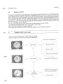
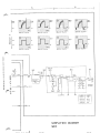
Fig.1 , shield connected to the couple-plate.
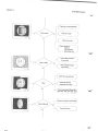
Fig.3 , II-generator mounted in the side box with
3 screws.
Fig.5 ,
connection of the II-tube to the shield
Fig.2 , couple-plate with BA1 board, the plastic
cover is already removed.
Fig.4 ,I pressure ring vastened at the side of the
shield. see also the centre-plates and the
adjustment screws.
Fig.6,
remove the vibration dampers and mount
them at the new II-tube.
00111m...
26
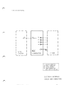
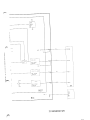
Section Z
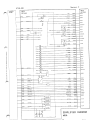
23cm Shield Assy for Surgery
BA
BV29 II/TV
AlAPTATIO\
r
BV29
STA\D
XTV8S
w<
C WK4X1
X4 X5
X7
C WK4X2
C WK4X3
OO WK4X4
X6 ©
U)
z
X
1
0z
0
X2
X2
0
Ls0
BA1
0
z
X3
X3
BGC1
0
0
X6
X6
X7 X7
X8
X8
X 9 --
-
X9
BB
23cm SHIELD ASSY FOR SURGERY
PHILIPS
I Philips Medical Systems
pa rts l i s t
Philips Medical Systems Nederland B.V. I Technical Service I Best
SERVICE PARTSLIST UNIT
PEI: 9807 603 60001
DESCRIPTION : CASSETTEHOLDER BV29
SERIAL NR:
List of pages and drawings
00"ok
P-00
(91.0)
P- 1
(91.0)
PZ-1
(91.0)
*printing instructions 4522 983 32271
(01 n1
P-00
Cassetteholder 8V29
Section P
INDEX
,
',
;SCHEME/
I CODENUMBER
.
.
1 1
IPZ- 1
:PZ- 1
IPZ- 1
IPZ- 1
IPZ- 1
IPZ- 1
1PZ- 1
IPZ- 1
:PZ- 1
IPZ- 1
:2622
14522
14522
12622
14522
14522
14522
14522
14522
12622
14522
I
I b
I c
d
e
1 f
: g
I h
1
j
: k
;PI- 1
.
.,,
:
1
.
115
128
103
115
128
128
128
128
128
115
128
00255
10051
87461
10002
10152
10062
10022
10032
10071
02372
10161
.
I2x
I2x
,
,
:Belleville washer
:fastener
:cap nut
;28x
:housing
(shaft
;knob
1
,
I
i
,
..
:
,
.
.
,
.
:
:
.
1
.
:
.
.
.
,
:
1
,
,
,
,
1
.
,.
:
.
1
.
:tension spring
lend stop
:cap
:compression spring
:clamping ring assy
,
.
.
.
.
.
,
.
.
,
.
.
.
1
a
1
,1
1DATA
1
.
.
.
.
.
.
;DESCRIPTION
:
.
:
,
:
;
:
,
I
,
:
,,
I
..
:
.
9Rn7 AA"(
I.
:
,.
;
:
..
.
knnnt
,
.
1
:
..
;
:,
I
:
,,
,.
,.
..
:
:
.,
1
..
.,
.,
,.
:
:
1
,,
,
;
:
PEI MANUALS
BV29
SERVICE PEI MANUALS
BV29 SYSTEM
MODULE CODE NUMBER 4522 983 52213
LIST OF PAGES AND DRAWINGS
0.1
(b/93.1)
0.6
(92.0)
0.7
(92.0)
2.1
(b/93.1)
BV29/PEI
(b/93.1)
2.1
rl"
SERVICE MANUAL - UNIT
Image Storage & Handling Extension
e.
.r:
ki
.1 5
itri
I ii;
"
0 ti ic
'
11:44=.191
0
88
I
:
11
De
!,_.........
R51
F5-1
i
',R.r4-451
. ,
-1 4*A
. 1
Fil F-P7
- ---
-_1)FeysTo
e P-1 ri FDIFtFAM. ireli.=
e
7,
Rn
r
.,•..
i
(
-
.
ie,1
DI SKINTERFACE I
POSTPROCESS ING
_
„
1
— --1
J
a* cl'i
This manual contains information on the IMAGE STORAGE & HANDLING EXTENSION
option.
IPSC: Best
Copyright © '92 PHILIPS MEDICAL SYSTEMS NEDERLAND B.V.
BEST THE NETHERLANDS
IRA CT R. 1-1A ► III PYT
(92.0)
1
IM. ST . & HAND. EXT.
IMAGE STORAGE & HANDLING EXT.
IMAGE STORAGE AND HANDLING EXTENSION
SERIAL NUMBER:
LIST OF PAGES AND DRAWINGS
0.5
1
2.1
(92.0)
(92.0)
(92.2) **
1-1
1-2
1-3
1-4
1-5
(92.1)E*
(92.1)E*
(92.1)E*
(92.1)E*
(92.2)E**
Printing instructions: 4522 983 52601
TM qq, k HAND. EXT.
(92.2)
2.1
Section IM. ST. & HAND. EXT.
BV29/BV26
IMAGE STORAGE & HANDLING EXT.
Section : Contents
oeN
e'N
INTRODUCTION 1-2
ITEMS SUPPLIED 1-2
COMPATIBILITY 1-2
INSTALLATION 1-3
UNIT TROLLEY 1-3
4.1.
MEMORY BOX
4.2.
DISK INTERFACE BOARD P7 AND POSTPROCESSING BOARD P8 1-4
4.3.
HARD DISK (WF) 1-4
SETTING TO WORK 1-5
CHECKING THE FUNCTIONS 1-5
Section IM. ST . & HAND. EXT.
BV29/BV26
INTRODUCTION
The IMAGE
- Storage
- Mosaic
- Zoom
- Measure
STORAGE AND HANDLING EXTENSION offers the following functions:
: 190 images on hard disk.
: displaying of 16 images from hard disk simultanuously.
: increasing the area of intrest.
: indicating the relative difference in vessel diameter of two selected cross sections.
ITEMS SUPPLIED
The following items are part of the delivery:
- NEC 3.5-in. Disk Drive.
Digital Scopof ix MMP Diskinterface board P7.
Digital Scopofix MMP Postprocessing board P8.
Cabling for connection between:
WFX2 - WHDP7J1 (flatcable)
WFX1 - WHDP7J2 (four wire cable)
Mounting material for Hard Disk:
( a mounting plate, 4 screws M4 with 4 spring washers, 4 screws M3 with 4 rivets and 4 spring washers and
4 ty-raps.)
3.
COMPATIBILITY
The IMAGE STORAGE & HANDLING EXTENSION is compatible with:
MMC 1102 (BV29)
MMC 1151 (BV26)
Section IM. ST . & HAND. EXT.
BV29/BV26
4.
INSTALLATION
4.1.
MEMORY BOX UNIT TROLLEY
For pulling out the complete Memory Box Unit (MBU) do:
Procedure BV26:
- Remove covers located at both sides of the trolley-keyboard (4 screws each side).
Pull out the MBU half way.
- Disconnect the connectors WTX1 + earth, WTX3, WTX2 and WTX4 to prevent damaging of the cables.
- Position the cables so that they can't be damaged when the MBU is pulled out completely.
Pull out the Memory Box Unit completely ( Unit is secured by blocking screws).
- Remove the EMC-plate at the left side of the MBU by removing the 20 screws.
- Remove the 2 PCB holding-plates ( 4 screws).
- Remove the blocking screw at the left side, so that the MBU can be pulled out a little bit more to have better
access to loosen the EMC-plate covering the location for the Hard Disk.
NOTE
REMOVE THE SCREWS CAREFULLY.
- Remove the EMC-plate covering the location of the Hard Disk (12 screws).
Procedure BV29:
- Remove covers located at both sides of the trolley-keyboard (4 screws each side).
- Pull out the Memory Box Unit completely ( Unit is secured by blocking screws).
- Remove the EMC-plate at the left side of the MBU by removing the 20 screws.
- Remove the 2 PCB holding-plates ( 4 screws).
- Remove the blocking screw at the left side, so that the MBU can be pulled out a little bit more to have better
access to loosen the EMC-plate covering the location for the Hard Disk.
NOTE
REMOVE THE SCREWS CAREFULLY.
- Remove the EMC-plate covering the location of the Hard Disk (12 screws).
Section IM. ST . & HAND. EXT.
4.2.
BV29/BV26
DISK INTERFACE BOARD P7 AND POSTPROCESSING BOARD P8
NOTE
USE ELECTROSTATIC DISCHARGE BRACELET WHEN PUTTING IN THE BOARDS
Procedure:
- Put DISKINTERFACE BOARD on postion P7.
- Put P OSTPROCESSING BOARD on position P8.
4.3.
HARD DISK (WF)
Procedure:
- Mount the HARDDISK on the mounting plate with 4 screws M3, 4 rivets and 4 spring washers.
NOTE
BEFORE MOUNTING THE HARDDISK MAKE SURE THAT THE INSERTS IN THE 4 VIBRATION DAMPERS
ARE CLEAR (NO RUBBER).
THE HARDDISK FLATCABLE CONNECTOR MUST BE LOCATED AT THE LEFT SIDE
- Mount the HARDDISK with mounting plate on the 4 vibration dampers.
Use the delivered mounting material (4 screws M4 and 4 spring washers).
- Connect cables:
. WFX1 - WHDP7-J2 ( four wire cable )
. WFX2 - WHDP7-J1 ( flat cable )
- Remount the PCB holding plates, both EMC-plates, blocking screw and covers.
Section IM. ST . & HAND. EXT.
BV29/BV26
SETTING TO WORK
5.
Leave the MMP-unit open.
Enter the SERVICE MENU.
Select the MBC UTIL & FREQUENCY menu (line 40).
Set CHANGE MODE in order to change current settings.
Put jumper WT2 : S1-5 in position on.
Select line 43 (Format disk).
Press <ACC> .
Give "Y".
- Wait until refreshed menu appears (after 5 sec).
Text in lower left corner: "FORMATTING DISK"
- Service menu appears after the DISK is formatted.
RETURN TO MAIN MENU.
EXIT SERVICE MENU.
Leave CHANGE MODE.
- Put jumper WT2 : S1-5 in position "OFF".
- Push back MMP-unit.
Tighten the four screws wich holds the MMP-unit.
6.
CHECKING THE FUNCTIONS
Check the functions of the IMAGE STORAGE & HANDLING EXTENSION:
SEE THE USER's MANUAL.
IIA C'T o
uAnin PVT
(92.21E
1-5
SERVICE MANUAL - UNIT
Angiography Extension
!1,7...,..,:i
J5
1§§
f.8881
i
..
1
- . .
Mr'
r' 1r, o.,..MFirsreAKAR-F-10 ...'
4
-}
--------
11----14
0E
I
-1
TI 1A
/ il
r----1,
II,.1
,..
i
•
,
1--
i
J
.]
- ; 1A-1-'
I
I
--
PROCESSING 2
Rl
i- R51
]
4 ,
This manual contains information on the ANGIOGRAPHY EXTENSION option.
IPSC: Best
Copyright © '92 PHILIPS MEDICAL SYSTEMS NEDERLAND B.V.
BEST THE NETHERLANDS
A
mnin
GYT
(92.01
1
BV29/BV26
ANGIO. EXT.
ANGIOGRAPHY EXTENSION
SERIAL NUMBER: /)
LIST OF PAGES AND DRAWINGS
0.5
1
2.1
(92.0)
(92.0)
(92.1)*
1-1
1-2
1-3
(92.0)E
(92.1)E*
(92.1)E*
Printing instructions: 4522 983 52611
ANC,Tn. EXT.
(92.1)
2.1
Section ANGIO. EXT.
BV29/BV26
ANGIOGRAPHY EXT.
Section :
Contents
INTRODUCTION 1-2
ITEMS SUPPLIED 1-2
COMPATIBILITY 1-2
INSTALLATION 1-3
SETTING TO WORK 1-3
CHECKING THE FUNCTIONS 1-3
Section IM. ST . & HAND. EXT.
BV29/BV26
INTRODUCTION
The IMAGE
- Storage
- Mosaic
- Zoom
- Measure
STORAGE AND HANDLING EXTENSION offers the following functions:
: 190 images on hard disk.
: displaying of 16 images from hard disk simultanuously.
: increasing the area of intrest.
: indicating the relative difference in vessel diameter of two selected cross sections •
ITEMS SUPPLIED
The following items are part of the delivery:
NEC 3.5-in. Disk Drive.
- Digital Scopofix MMP Diskinterface board P7.
- Digital Scopof ix MMP Postprocessing board P8.
Cabling for connection between:
WFX2 - WHDP7J1 (flatcable)
WFX1 - WHDP7J2 (four wire cable)
Mounting material for Hard Disk:
( a mounting plate, 4 screws M4 with 4 spring washers, 4 screws M3 with 4 rivets and 4 spring washers and
4 ty-raps.)
3.
COMPATIBILITY
The IMAGE STORAGE & HANDLING EXTENSION is compatible with:
MMC 1102 (BV29)
MMC 1151 (BV26)
Section ANGIO. EXT.
BV29/BV26
4.
INSTALLATION
Procedure BV26:
Remove covers located at both sides of the trolley-keyboard ( 4 screws each side).
- Pull out the Memory Box Unit (MBU) half way.
- Disconnect the connectors WTX1 + earth, WTX3, WTX2 and WTX4 to prevent damaging the cables.
- Position the cables so that they can't be damaged when the MBU is pulled out completely.
Pull out MBU completely ( unit is secured by blocking screws).
- Remove the EMC-plate at the left side of the MBU by removing 20 screws.
- Remove the 2 PCB holding-plates (4 screws).
- Remove the -dummy- PROCESSING 2 BOARD on position P3.
- Place the PROCESSING 2 BOARD on position P3.
Exchange the footswitch with the delivered footswitch.
- Reassemble in reverse order.
Procedure BV29:
- Remove covers located at both sides of the trolley-keyboard ( 4 screws each side).
- Pull out MBU completely ( unit is secured by blocking screws).
- Remove the EMC-plate at the left side of the MBU by removing 20 screws.
- Remove the 2 PCB holding-plates (4 screws).
- Remove the -dummy- PROCESSING 2 BOARD on position P3.
- Place the PROCESSING 2 BOARD on position P3.
- Exchange the footswitch with the delivered footswitch.
Reassemble in reverse order.
SETTING TO WORK
5.
NOTE
NO SETTING TO WORK INSTRUCTIONS HAVE TO BE CARRIED OUT AFTER INSTALLATION OF
THIS OPTION.
6.
CHECKING THE FUNCTIONS
Check the functions of the ANGIOGRAPHY EXTENSION:
SEE THE USER's MANUAL.
A mnia CVT
(Q2 11F
1-3
SERVICE MANUAL - UNIT
Video Memory Extension for ArImages
Val!!
n i #11 .., ,--ei
(D 3 3
11
m rn FDIR-4011-4-FilM. reire.-1 ". .
R-71
-,
. . . .
E
f
!
F-I
.
,
cat
V131) MEMORY EXT ENSION
---41-3-1
$.
1
[
1
I.
•
i
R: I M
/
1 4-A
32 /€,1 .__._,
, I
9900
(f-----1
J
i • .i • I*
a - IA -•
:
This manual contains information on the VIDEO MEMORY EXTENSION FOR 32
IMAGES option.
IPSC: Best
Copyright © '92 PHILIPS MEDICAL SYSTEMS NEDERLAND B.V.
BEST THE NETHERLANDS
y in
RACRA =VT
19
IRA
BV29/BV26
VID. MEM. EXT. 32 IM.
VIDEO MEMORY EXTENSION FOR.,30fIMAGES
SERIAL NUMBER:
//
2?
LIST OF PAGES AND DRAWINGS
0.5
1
2.1
(92.0)
(92.0)
(92.1)*
1-1
1-2
1-3
(92.0)E
(92.1)E*
(92.1)E*
Printing instructions: 4522 983 52621
7T T1
TAMAX
"C",V,T, "2') TM
Section VID. MEM. EXT. 32 IM.
BV29/BV26
VIDEO MEMORY EXTENSION FOR 32 IMAGES
Contents
INTRODUCTION 1-2
ITEMS SUPPLIED 1-2
COMPATIBILITY 1-2
INSTALLATION 1-3
SETTING TO WORK 1-3
CHECKING THE FUNCTIONS 1-3
Section VID. MEM. EXT. 32 IM. INTRODUCTION
The VIDEO MEMORY EXTENSION FOR 32 IMAGES offers the following functions:
- 32 image video memory for cine display.
- Replay last FLUORO scene.
- Selectable acquisition frame speed.
- Cine loop editing.
ITEMS SUPPLIED
The following item is part of the delivery:
- Digital Scopofix MMP CINE MEMORY BOARD P5.
3.
COMPATIBILITY
The VIDEO MEMORY EXTENSION FOR 32 IMAGES is compatible with:
MMC 1102 (BV29)
MMC 1151 (BV26)
BV29/BV26
Section VID. MEM. EXT. 32 IM.
BV29/BV26
4.
INSTALLATION
Procedure BV26:
Remove covers located at both sides of the trolley-keyboard ( 4 screws each side).
- Pull out the Memory Box Unit (MBU) half way.
Disconnect the connectors WTX1 + earth, WTX3, WTX2 and WTX4 to prevent damaging the cables.
- Position the cables so that they can't be damaged when the MBU is pulled out completely.
Pull out MBU completely ( unit is secured by blocking screws).
- Remove the EMC-plate at the left side of the MBU by removing 20 screws.
- Remove the 2 PCB holding-plates (4 screws).
- Place the CINE MEMORY BOARD on position P5.
- Reassemble in reverse order.
Procedure BV29:
Remove covers located at both sides of the trolley-keyboard ( 4 screws each side).
Pull out MBU completely ( unit is secured by blocking screws).
- Remove the EMC-plate at the left side of the MBU by removing 20 screws.
Remove the 2 PCB holding-plates (4 screws).
- Place the CINE MEMORY BOARD on position P5.
- Reassemble in reverse order.
5.
SETTING TO WORK
NOTE
NO SETTING TO WORK INSTRUCTIONS HAVE TO BE CARRIED OUT AFTER INSTALLATION OF
THIS OPTION.
"10°'n
6.
CHECKING THE FUNCTIONS
Check the functions of the VIDEO MEMORY EXTENSION FOR 32 IMAGES:
SEE THE USER's MANUAL.
SERVICE MANUAL - UNIT
23cm shield assy for surgery
9896 010 02311
For serial numbers, see list of pages and drawings
This manual contains descriptive information on the equipment identified by the number
stated above. For information on specific application, see the system manual.
IPSC: Best
Copyright © '93 PHILIPS MEDICAL SYSTEMS NEDERLAND B.V.
BEST THE NETHERLANDS
Printati
in Tha Kintlinrinnric ra g n1
1
23cm shield assy for surgery
SERVICE MANUAL-UNIT
23cm shield assy for surgery
: 9896 010 02311
TYPE NO.
SERIAL NO.
Manual codenumber : 4522 983 54411
List of Pages and Drawings
0.5
1
2
(93.0)
(93.0)
(93.0)
3
4
5
6
7
8
(93.0)
(93.0)
(93.0)
(93.0)
(93.0)
(93.0)
25
26
(93.0)
(93.0)
Z1-1
Z2-1
Z3-1
(93.0)
(93.0)
(93.0)
OCIOg nm n /10Q1 I
laq
\
2
23cm shield assy for surgery
Contents
1.
Introduction and technical data 4
1.1.
Purpose 4
1.2.
Items supplied 4
1.3.
Equipment identification 4
1.4.
1.4.1.
1.4.2.
1.4.3.
1.4.4.
1.4.5.
Technical data Dimensions and weights Protections Compatibility Adaptations Applicable standards 4
4
4
5
5
5
2.
Installation 6
2.1.
Tools 6
3.
Replacements 6
3.1.
Remove the shield assy from the stand 6
3.2.
Exchanging the II/TV adaptation PCB (BA1) 6
3.3.
Exchanging the HT II-generator 6
3.4.
Exchanging the II-tube 7
3.5.
Mount the shield assy to the stand
4.
Adjustments 8
4.1.
Adjustment facilities 8
4.2.
Electrical focusing adjustment 8
7
ILLUSTRATIONS AND DRAWINGS
25
Equipment identification Illustrations for replacement procedures Interface diagram Cabling BV29 II/TV adaptation °ROA fin ri9r4i
26
Z1-1
Z1 -2
Z1-3
(93.01
3
23cm shield assy for surgery
1.
INTRODUCTION AND TECHNICAL DATA
1.1.
PURPOSE
This 23 cm II tube assembly is applied in the BV29 system. The shield has been designed for housing; a 23cm
II-tube, a basic lens, an XTV-8SRI camera, an adaptation board and an II-generator in the II side box.
1.2.
ITEMS SUPPLIED
The numbers in the list refer to the items in figure (a) on page 25.
shield with side box
camera cover
couple-plate
hand-grip (2x)
5.
6.
7.
8.
pressure ring
finishing ring with implosion plate, u.-metal ring + lead ring
vibration dampers
BV29 II/TV adaptation board BA1
In plastic bag:
4 screws M4 x 10 for mounting a grid on the finishing ring.
4 identification plates, see info at para. 1.3.
cabling set (6 cables) as shown on drawing Z2-1.
1.3.
EQUIPMENT IDENTIFICATION
The identification plates are located on the central labelling station of the system and on the inner side of the
camera cover as indicated on page 25. Included are the following plates:
Name and Address plate.
-
Type number plate with serial number of the 23 cm II tube assy
Manufacturer plate.
HHS certification label.
HHS date of manufacture.
UUCSA classification mark.
NOTE
In case of replacement of certifiable items always replace duplicate label on the inside of the camera cap
and on the central labelling station "i" of the BV29.
1.4.
1.4.1.
TECHNICAL DATA
Dimensions and weights
Overall dimensions: see drawing Z9-1, total weight: - 200 N = - 20 kg.
1.4.2.
4
Protections
X-Rays
The shield, camera cover and other relevant parts are provide with a lead lining to
protect the environment against radiation of x-ray beams which are projected
perpendicular to the entrance screen
Magnetic shielding
The shield is provided with pi-metal to minimize the effect of weak alternating or static
magnetic fields inside the container. All parts of the shield are made of non-magnetic
material.
Mechanical
In case the II tube implodes, an implosion plate protects the environment against
fragments of the tube.
(93.0)
9896 010 02311
23cm shield assy for surgery
lam'`
1.4.3.
Compatibility
The 23cm shield assembly for surgery is compatible with the following items:
23cm II-generator non blanking
23cm II-tube
XTV-8SRI camera
mobile surgery stand BV29
1.4.4.
Adaptations
The 23 cm II tube assembly can be adapted to the following equipment, which are no part of this assembly:
Mobile stand BV29
The couple-plate is the interface between the BV 29 Stand and the shield
assembly. The cable of the stand leading to the shield has to be fitted to the
connector X1 of the II/TV adaptaion board BA1 on the couple-plate and to the
earth point on the cable relief bracket.
XTV-8SRI camera
the basic lens is fitted to the II-tube with three adjusting bolts in the centring
ring. The XTV camera can be mounted directly to the basic lens with a quick
locking device.
II compact generator
Can be mounted in the II side box.
23 cm multi mode
II-tube
The II-tube must be fitted in the container in one position (markers are on the
shield and on the tube).
Grid
The grid is screwed to the front of the container.
Service phantom plate
After removing of the grid a phantom plate can be fitted in two positions (90°
rotated) to the front of the container.
1.4.5.
Applicable standards
The following standards are applicable to the 23 cm II tube assembly.
PR•
PMS products are developed and manufactured with observance of a number of directives, regulations and
standards. (e.g. International product safety standards as IEC, ISO, CISPR and national performance and
product safety as 21CFR Subch. H and J, U.L., CSA, DIN and VDE.)
Information regarding the compliance status with standards and product approvals is obtainable at:
Philips Medical Systems
Corporate Quality Department
Regulation and approbation Group
Building QM 118
PO Box 10,000
5680 DA BEST
The Netherlands
Fax. No.
3 1-4 0-762205/762420
Tel. No.
31-40-762408
Telex No.
35000 PHTC NL
routing indicator XLQBUXA
9896 010 02311
(93.0)
Conyrioht 0 1993 Phili ps Medical Systems International HAL
5
23cm shield assy for surgery
INSTALLATION
Normally the shield-assy is delivered in a factory assembled and -adjusted I I/TV-subsystem and no mechanical
adjustments are required in the field.
2.1.
TOOLS
This assembly can be installed with a standard toolset.
REPLACEMENTS
3.1.
REMOVE THE SHIELD ASSY FROM THE STAND
move the shield assy towards the stand (+ 90° skew), the X-ray tank is pointing in the air now
support the X-ray tank (with a table or a chair) in such a way that you can not move the C-bow
Warning
When the shield assy is removed there is a large force (from the X-ray tank) pointing in the air.
Support the X-ray tank for your own safety.
(7)
3.2.
remove the top cover from the shield
disconnect all the cables from the II/TV adaptation PCB
remove the two hand grips from the shield
disconnect WK4: X1, X2 and X3 from the camera, loosen the camera locking devise and remove the
camera from the basic lens
remove the 6 screws from the couple-plate see Fig.1 page 26
EXCHANGING THE II/TV ADAPTATION PCB (BA1)
execute paragraph 3.1.
remove the plastic cover infront of the PCB (2 screws)
remove the PCB from the couple-plate (4 screws) see Fig.2 page 26
disconnect BA1:X1 from the defective PCB and connect the new PCB
mount the new PCB to the couple-plate and the plastic cover to the PCB
execute para. 3.5.
3.3.
(7)
6
EXCHANGING THE HT II-GENERATOR
execute paragraph 3.1.
disconnect BGC1: X6, X7, X8 and X9 from the HT-unit
remove the HT-unit (3 screws) from the shield see Fig.3 page 26
disconnect BGC1: X2 and X3, connect the cables X2 and X3 to the new HT-unit
mount the HT-unit to the shield (3 screws)
connect BGC1: X6, X7, X8 and X9
execute para. 3.5.
(93.0)
9896 010 02311
23cm shield assy for surgery
3.4.
EXCHANGING THE H-TUBE
execute paragraph 3.1.
disconnect BGC1: X6, X7, X8 and X9 from the HT-unit and the earth lead from BA1
remove the basic-lens from the II-tube (3 screws)
remove the X-ray grid (4 screws)
remove the finishing ring form the shield (4 screws)
remove the ring with implosion plate
loosen the: 3 centre-plates (2 screws each) on the pressure ring, Fig.4 page 26
3 bolts (to unlock the adjusting screws)
3 adjusting screws, see also the top-left Fig. 10 on page 25
remove the pressure ring (7 screws see also the top-left Fig. item 12 page 25)
see Fig.5 page 26 remove the 3 bolts from the shield
remove the shield from the II-tube guide the cables through the cable outlet of the shield
remove the 3 vibration dampers from the II-tube and mount them to the new II-tube
guide the cables of the new II-tube through the outlet of the shield and move the tube into the shield.
Fit the tube so that the marker on the tube is in line with the marker on the shield, see the top-right
figure at page 25
mount the tube to the shield with 3 bolts, see Fig.4
possition the pressure ring in the shield so that the opening of the ring is in the middle of the side box
vasten the pressure ring (7 screws see top-left Fig. item 12 page 25) begin at one side of the opening
(of the pressure ring) and move onwards untill you reach the other side of the opening of the ring.
turn the adjustment screws (3) untill you feel a resistance and lock them with the bolt
mount the ring with implosion plate; the finishing ring and finaly the grid to the shield
mount the basic lens carefully to the II-tube (3 screws)
connect BGC1: X6, X7, X8 and X9 to the HT-unit and the earth lead to BA1, see Fig.3 page 26
(19) execute para. 3.5.
3.5.
MOUNT THE SHIELD ASSY TO THE STAND
mount the shield assy back to the couple-plate (on the stand), with 6 screws see Fig.1 page 26
mount the camera to the basic lens and connect WK4: X1, X2 and X3 to the camera
mount the two hand grips to the couple-plate
connect all the cables to the II/TV adaptation PCB
mount the top cover to the shield
9896 010 02311
Ann .,
(93.0)
7
it,rvn 1 la %/
23cm shield assy for surgery
4.
ADJUSTMENTS
Normally the shield-assy is delivered in a factory assembled and -adjusted II/TV-subsystem and no electrical
adjustments are required in the field.
4.1.
ADJUSTMENT FACILITIES
On the BV29 II/TV adaptation board the following adjustments have to be executed:
BA1:R1, focusing for 13 cm format
BA1:R2, focusing for 17 cm format
BA1:R3, focusing for 23 cm format
The measuring points on this board are:
BA1:MP1, FSM focusing service mode (cathode voltage for each format)
BA1:MP2, FSMR focusing service mode reference (OVref)
BA1:MP3, Video out signal
4.2.
ELECTRICAL FOCUSING ADJUSTMENT
General: Stay out of the primary X-ray during focusing of the II-Generator.
Adjustment procedure:
remove all the filters between the X-Ray Tube and the II Tube
mount a 23 cm holder with funk phantoms in front of the II
select the 23 cm II-format
connect a multimeter between BA1:MP1 and BA1:MP2 on the Adaptation Board (BA1) in the side-box
of the shield.
switch on fluoroscopy in automatic mode.
adjust the focusing voltage (VC) of the II-tube to a optimum with potentiometer BA1:R3
switch off fluoroscopy
select the 17 cm II-format
switch on fluoroscopy in automatic mode
adjust the focusing voltage (VC) of the II-tube to a optimum with BA1:R2
switch off fluoroscopy
select the 13 cm II-format
switch on fluoroscopy in automatic mode
adjust the focusing voltage (VC) of the II-tube to a optimum with BA1:R1
switch off fluoroscopy
note down the focusing-value, (BA1:MP1 and MP2) of each format, on a measuring sheet.
8
han n1
none A1 A nr1 •31 1
23cm shield assy for surgery
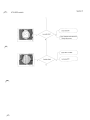
Fig.1 , shield connected to the couple-plate.
Fig.2 , couple-plate with BA1 board, the plastic
cover is already removed.
Fig.3 , II-generator mounted in the side box with
3 screws.
Fig.4 , pressure
ring vastened at the side of the
I
shield. see also the centre-plates and the
adjustment screws.
Fig.5 ,
connection of the II-tube to the shield
noon fli rn 110011
Fig.6,
remove the vibration dampers and mount
them at the new II-tube.
9R
23cm Shield Assy for Surgery
Section Z
BA
BV29 II/TV
ADAPTATION
r
BV29
STAND
X4
X5
X7
XTV8S
WK
WK4X1
C
WK4X2
C
WK4X3
WK4X4
X6
Efri
—J
C
_J
Cr
41
(0
X2
X2
La_
0
LAJ
BA1
F—
F0
X3
X3
B3C 1
co
co
cn
0
X6
X6
X7
X7
X8
X8
X9
X9
- 4
BB
23cm SHIELD ASSY FOR SURGERY
(AIM 01'3'31
(Q) Oh
71-1
SERVICE MANUAL - UNIT
II GEN. 23CM NON-BLANKING
9807 141 6..01
For serial numbers, see list of pages and drawings
This manual contains descriptive information on the equipment indentified
by the number stated above. For information on specific application,
see relevant II TV Subsystem manual.
PMSN Best
ro***-
Copyright Philips Medical Systems International B.V.
All rights are reserved. Reproduction in whole or in part is prohibited without the written consent of the copyright owner.
Use of the information contained herein in any form and/or by any means whatsoever is strictly reserved for Philips and its licensees.
Use of this manual by unauthorised persons is strictly prohibited.
Inn
IN
II GEN. 23cm NON-BLANKING
SERVICE MANUAL-UNIT
II GEN. 23cm NON-BLANKING
: 9807 141 61001
TYPE NO.
SERIAL NO.
Manual codenumber : 4522 983 18051
List of Pages and Drawings
0.5
1
2
(92.0)
(92.0)
(92.0)
3
4
5
6
7
8
(92.0)
(92.0)
(92.0)
(92.0)
(92.0)
(92.0)
25
26
(92.0)
(88.0)
Z1-1
(92.0)
Z2-1
(88.0)
Z3-1
Z3-2
(92.0)
(88.0)
r's
4 A 4
n4
too O\
2
II GEN. 23cm NON-BLANKING
Contents
Introduction and technical data 4
1.1.
Purpose 4
1.2.
Items supplied 4
1.3.
Equipment identification 4
1.4.
1.4.1.
1.4.2.
1.4.3.
1.4.4.
Technical data Dimensions and weights Electrical data II-generator Environmental data
Applicable standards 4
4
5
6
6
Installation 7
2.1.
Introduction 7
2.2.
Tools 7
2.3.
Mounting material 7
2.4.
Installation instructions 7
Setting to work 8
8
3.1.
Introduction 3.2.
Test equipment 8
3.3.
3.4.
Adjustment information Service controls and measuring points 8
8
Corrective maintenance 8
II GEN. 23cm NON-BLANKING
1.
INTRODUCTION AND TECHNICAL DATA
1.1.
PURPOSE
The high tension II-generator, 9807 141 6..01, has been developed to supply the 23cm single and multi mode
31 II-tubes. The generator consists of a Focus Service Board and a High Tension Cascade Unit. These parts
are mounted within the side box of the II-container.
The high tension cascade unit provides the II-tube with the following high tension voltages:
Anode 1 Voltage VA1
: Constant
Anode 2 Voltage VA2
: Format dependent
Focusing 1 Voltage VF1 : Earth potential
Cathode Voltage VCT
: Format dependent (focusing)
1.2.
ITEMS SUPPLIED
See page 25
High tension cascade unit.
Focus service board.
Connection cable.
Mounting material for fitting the high tension cascade unit and the focus service board in the side box
of the II-container.
1.3.
EQUIPMENT IDENTIFICATION
The location of the identification plates can be found as shown on page 25.
1.4.
TECHNICAL DATA
1.4.1.
Dimensions and weights
Dimensions of high tensin cascade unit: L x W x H = 200 x 130 x 50 mm
Total weight:
30 N =
3 kg.
4
inn rl
I,
•
• J
••n
II GEN. 23cm NON-BLANKING
1.4.2.
Electrical data II-generator
The II-generator consists of a cast in high tension cascade unit and a separate focus service board.
All the H.V. output voltages are short circuit proof.
Input data :
- Supply voltage: + 15 V + 5 %, !max: 0.5 A.
- 15 V + 5 %, 'max: 0.5 A.
Output data (voltages) :
Connector
II-format
Nominal output
Anode 1 (VA1)
All formats
+ 25
Anode 2 (VA2)
23 cm
17 cm
13 cm
+ 8 KV ±
+ 15.5 KV ±
+25 KV ±
Focus 1 (VF1)
All formats
Cathode (VCT)
23 cm
17 cm
13 cm
0
KV ±
V
- 275 ± 50 V
- 215 ± 50 V
- 205 ± 50 V
NOTE
lonpump voltage not present, external supply needed.
Output data (current) :
max (Anode 1) = 10 uA
'max (Anode 2) = 10 uA
!max (Cathode) = 40 uA
Control signals II-generator - II/TV system
Signal
Code
explanation
II format code 0
II format code 1
IFCO..L
IFC1..L
For detailed information see drawing Z1-1
II generator ready
IGRD..L
When the supply voltage of the generator is at an operationel
level, IGRD..L will be low active.
Service mode II generator
SMIG..L
Selection of service mode operation of the II-generator for
remote focusing.
Service mode focusing
SMFO..A
Cathode reference voltage from a potentiometer in the II/TV
system for remote focusing adjustment.
II GEN. 23cm NON-BLANKING
Control signals Focus service board / High tension cascade unit
Voltage Reference For Cathode Voltage 1 : VREFVC1
Voltage Reference For Cathode Voltage 2 : VREFVC2
Voltage Reference For Cathode Voltage 3 : VREFVC3
Connection cable Focus service board - High tension cascade unit
Focus service board
High tension cascade unit
function
BGC2X1 (MOD V)
BGC1X2 (MOD V)
Cathode reference voltages
Switching delay-time
The switching delay-time between the different formats never exceeds 0.8 second.
1.4.3.
Environmental data
Ambient temperature
Relative humidity
Heat emission
1.4.4.
: + 10 °C / + 40 °C
: + 2 0 % / + 9 0 `)/0
. 10 Watt
Applicable standards
PMS products are developed and manufactured with observance of a number of directives, regulations and
standards. (e.g. International product safety standards as IEC, ISO, CISPR and national performance and
product safety as 21CFR Subch. H and J, U.L., CSA, DIN and VDE.)
Information regarding the compliance status with standards and product approvals is obtainable at:
Philips Medical Systems
Corporate Quality Department
Regulation and approbation Group
Building QM 118
PO Box 10,000
5680 DA BEST
The Netherlands
Fax. No.
31-40-762205/762420
Tel. No.
31-40-762408
Telex No.
35000 PHTC NL routing indicator XLQBUXA
II GEN. 23cm NON-BLANKING
2.
INSTALLATION
2.1.
INTRODUCTION
This section contains general mounting instructions and programming data. For installation information relating
to the specific II/TV subbsystem interfaces, see the relevant II/TV subsystem manual.
2.2.
TOOLS
The II-generator can be installed with a standard toolset.
2.3.
MOUNTING MATERIAL
Mounting material for fitting the high tension cascade unit to the mounting plate in the side box of the IIcontainer: - 3 washers 3.2 x 7
- 3 spring washers 3.1 x 6.2
- 3 screws M3 x 8
Mounting material (see page 25) for fitting the focus service board to the mounting plate in the side box of the
II-container: (a) 4 washers 2.7 x 6.5
4 spring washers 2.6 x 5.1
4 screws M2.5 x 20
16 print supports
1 bracket
(f) 2 screws M4 x 6
2.4.
INSTALLATION INSTRUCTIONS
The high tension cascade unit has to be fitted together with the stand cabling or a special cable harness to
a mounting plate in the side box of the II-container. Use the mounting material as mentioned in paragraph 2.3.
Depending on the system, use one of the two mounting possibilities of the focus service board to the mounting
plate in the side box of the II-container. If both possible, use possibility number 1.
To the inside of the 34p M block frame opposite the 34p M block for the TV camera. Use mounting
material (a),(b),(c) and (d).(see paragraph 2.3.)
Opposite the ornamental hose inlet. Use mounting material (a),(b),(c),(d),(e) and (f).(see paragraph 2.3.)
The installation instructions and all data concerning the electrical connections of the II-generator are given in
the relevant II/TV subsystem manual.
NOTE
Be sure that the protection cover remains on the VA2 plug BGCX7 when the ll-generator is used for a single
mode ll-tube.
nn
\
7
II GEN. 23cm NON-BLANKING
3.
SETTING TO WORK
3.1.
INTRODUCTION
The output voltages of this 23 cm II-generator are factory adjusted (the potentiometers BGC1:R1/R2/R3/R4
has been sealed), with the exception of the cathode voltage VCT for each II-format. The cathode voltages
must be adjusted in an operational X-ray system. Instructions concerning the adjustments, see
the relevant II/TV subsystem manual.
3.2.
TEST EQUIPMENT
DIGITAL MULTIMETER:
3.3.
RI >. 10 MOHM
VDcACCURACY 0.5 `)/0
4 DIGIT
ADJUSTMENT INFORMATION
- Cathode voltage adjustment information (focusing).
The signal SMIG..L is used by the II/TV system to place the II-generator in the service mode. When active,
the internal reference of the VCT supply is disabled and a single potentiometer in a control unit of the II/TV
system in the II/TV cabinet is used for remote focusing of all available II-formats.
The final focusing is done by copying of the value measured for each II-format during remote focusing to the
corresponding potentiometer on the focus service board. The value for each II-format measured on point
BGC2: MP1-MP2 is an input cathode reference voltage for the actual cathode voltage VCT. The actual
cathode voltage cannot be measured.
3.4.
SERVICE CONTROLS AND MEASURING POINTS
Adjustment facilities on the focus service board BGC2.
BGC2:R1 adjustment cathode voltage (13 cm)
BGC2:R2 adjustment cathode voltage (17 cm)
BGC2:R3 adjustment cathode voltage (23 cm)
Measuring points on the focus service board BGC2.
BGC2:MP1 FSM : focus set monitor (cathode ref. voltage for each II-format)
BGC2:MP2 FSMR: focus set monitor return (0 Vref)
4.
CORRECTIVE MAINTENANCE
The high tension cascade unit is not repairable.
If it is defect, order a new II-generator by the commercial department.
II GEN. 23CM NON-BLANKING
ITEMS SUPPLIED
Identification Plates
oom•-‘
EQUIPMENT IDENTIFICATION
75
11 Gen. 23cm , ► on-Blanking
1
›MO
II/TV
L SYSTEM_ I
_J
II TUBE_
D = DECADE CONNECTOR
MO = MOD V CONNECTOR
0 =SCREW TERMINAL
® =HIGH TENSION PLUG
PART OF THIS UNIT
ELECTRICAL INTERFACE
CABLES AND CONNECTORS
15V
1
UNDER
VOLTAGE
LOCK
OUT
C
Do,
15 V
VF1
FOCUSSING
OVREF
OV
-250 V I 100V
CATHODE
HIGH VOLTAGE
GENERATION
ANODE 2
.10vREF
RI.
I
I0
ANODE 1
BB
vREF
BGC 1
BGC 1 2
BGC
II GENERATOR
Section Z
I.I. Gen. 23cm,Non-Blanking
BGC2
B1 Al BGC1X :Al
BGC1X3:B1
•
•
•
•
•
X1
-•
E
0
x
O
B1 Al BGC2X1
BG C 2X11B1
•
•
•
•
•
X81
•
•
• X2
•
X7
BGC
X910
X9:2
GN YE \
BA1
GN YE
X8
VF1
X82
BGC1
•
X6
V Al
X6
X3
CABLING
•
X7
VA 2
X9
VCT
I.I. Gen. 23cm , Non-Blanking
Section Z
4
X 64-- /6111.
X8
X82
X7
t.SE
B GC(1)
HIGH TENSION
CASCADE UNIT
Section Z
I.I. Gen. 23cm ,Non-Blanking X1 :A1
10VREF
£C1
i R1
'4..4-
7100n
ILR3
2
41-
jr
X1 :A2
OVREF
RI.C3
1C4
•••
10n
10n
710n
X1:A4
VREFVC3
X1:B4
VREFVC2
VREFVC1
0
X1:132
MP1
0 X1131
FSM
FSMR
0-
O
MP2
X1 :B3
0
FSM
0
FSMR
00
9
RI
L=I
A5
O R7
el
:a al,
I.
d3
R3
I
C1
I
XI
O
BGC2
FOCUS SERVICE BOARD
4522 108 09501
SERVICE MANUAL - UNIT
XTV-8SRI camera
9896 010 022 8
9
For serial numbers, see list of pages and drawings
This manual contains descriptive information on the equipment identified by the number
stated above. For information on specific application, see the system manual.
PMSN Best
Copyright @ 1993 Philips Medical Systems International B.V.
All rights are reserved. Reproduction in whole or in part is prohibited without the written consent of the copyright owner.
Use of the information contained herein in any form and/or by any means whatsoever is strictly reserved for Philips and its licenses.
Use of this manual by unauthorised persons is strictly prohibited.
INTRODUCTION & TECNICAL DATA
XTV-8SR I Camera
INSTALLATION
REPLACEMENTS
3 In
PROGRAMMINGS
PARTS LIST
DRAWINGS
9896 010 022 89 •
(93.0)
Copyright © 1993 Philips Medical Systems International B.V.
ALL RIGHTS RESERVED
n
2
FAULT FINDING
ADJUSTMENTS
1
4
5
6
P
z
2
XTV-8SRI camera
SERVICE MANUAL-UNIT
XTV-8SRI camera
TYPE NO. : 9869 010 0241
SERIAL NO.:
Manual codenumber: 4522 983 53511
LIST OF PAGES AND DRAWINGS
0.5
1
2
2.1
(93.0)
(93.0)
(93.0)
(93.1)
1-1
1-2
1-3
1-4
1-5
1-6
1-7
(93.0)
(93.0)
(93.0)
(93.0)
(93.0)
(93.0)
(93.0)
*
5-1
5-2
5-3
(93.0)
(93.0)
(93.1)
(93.0)
6-1
(93.0)
6-2
(93.1) *
6-3
(93.1) *
6-4
6-5
(93.1) *
(93.0)
2-1
(93.1) *
6-6
(93.0)
6-7
(93.0)
3-1
3-2
(93.0)
(93.0)
3-3
Parts list (4522 983 33961)
(93.0)
3-4
3-5
(93.1) *
P-00 (93.1) *
(93.1) *
3-6
if"
(93.1) *
P- 1
3-7
(93.0)
PZ-1 (93.0)
(93.0)
3-8
(93.0)
3-9
(93.1) *
ZO
3-10 (93.0)
Z1-0 (93.0) *
3-11 (93.0)
Z1-1 (93.0)
3-12 (93.0)
Z1-2 (93.0)
3-13 (93.0)
Z1-3 (93.0)
3-14 (93.0)
Z2-1 (93.0)
3-15 (93.0)
Z2-2 (93.0)
Z3-1 (93.0)
4-1
(93.0)
Z6-1 (93.0)
(93.0)
4-2
(93.0)
4-3
(93.0)
4-4
Copyright 0 1993 Philips Medical Systems International B.V. All rights
reserved. Reproduction in whole or in part is prohibited without the written
consent of the copyright owner. Use of the information contained herein in
any form and/or by any means whatsoever is strictly reserved for Philips and
its licensees. Use of this manual by unautorized persons is strictly prohibited.
93-05-05
4522 983 53511
1
I
5600
1;: : : :
.. ,:i„ ....,,,i1
I A4
"IN
Section 1
XTV-8SRI camera
Introduction & Technical data
Section 1:
Contents
1-2
Purpose #01.'
1-2
1.1.
Definition of terms
1.2.
Versions
1.3.
Items supplied 1-3
1.4.
Equipment identification 1-3
Technical data 1-3
2.1.
2.1.1.
2.1.2.
2.1.3.
2.1.4.
2.1.5.
2.1.6.
2.1.7.
2.1.8.
Performance data General Optics CCD-imaging and preprocessing Gain control Automatic dose control Video output signal (VIBS) Iriscontrol Camera rotation 1-3
1-3
1-5
1-5
1-5
1-5
1-5
1-6
1-6
2.2.
Dimensions and weight 1-6
2.3.
Supply requirements 1-6
2.4.
Environmental data 1-6
2.5.
Compatibility
1-6
2.6.
Applicable standards 1-2
40111%.
1-7
Section 1
1.
XTV-8SRI camera
PURPOSE
The XTV-8SRI camera is a major upgrade of the first generation XTV-8 CCD camera. The XTV-8S camera
is meant for standard class fluoroscopy examinations in conjunction with:
23 cm single channel multi-mode Image Intensifier (for surgery stands)
15 cm single channel one mode II (for surgery stands).
1.1.
DEFINITION OF TERMS
The following terms/mnemonics are used in this manual:
ADC
AGC
assy
CCD
CCIR
cw
ccw
DRFLDNA
DRFLDPA
EIA
Automatic Doserate Control
Automatic Gain Control
assembly
Charge Coupled Device
European video standard
clock wise
counter clock wise
Doserate Fluoroscopy Differential Signal Negative Analog
Doserate Fluoroscopy Differential Signal Positive Analog
American video standard
Image Intensifier
Measuring Field
Remote Control stand
Radiography Fluoroscopy stand
Video after AGC
Video with Blanking and Sync. (= composite video out)
Video from Camera (without sync. before AGC/ADC)
MF
RC
RF
VIAGC
VIBS
VICA
1.2.
VERSIONS
The camera will be delivered in 2 versions. The differences between the versions are in the type of video
produced.
XTV-8SRI/50
50 Hz rotatable camera
with iris remote control
9896 010 02281
XTV-8SRI/60
60 Hz rotatable camera
with iris remote control
9896 010 02291
The 50 Hz version, produces an CCIR (625 lines interlaced) composite video output.
The 60 Hz version, produces an EIA (525 lines interlaced) composite video output.
tieb`
XTV-8SRI camera
1.3.
Section 1
ITEMS SUPPLIED
See the figure
(1) camera SRI version
1.4.
EQUIPMENT IDENTIFICATION
Equipment identification is located on the inside of the camera cap and on the central labelling station "I" of
the stand.
NOTE
In case of replacement of the certifiable items, always replace
the duplicate label on the places mentioned above.
2.
TECHNICAL DATA
2.1.
PERFORMANCE DATA
2.1.1.
General
The XTV-8SRI has:
very good resolution through: • a CCD with 750 horizontal pixels
• optimal use of the CCD sensor area through elliptical projection
good signal to noise ratio, minimum lag
service adjustable irisdiaphragm with position detection
service selectable sync. modes, X-tal/rnains lock
user selectable AGC gain modes; fixed, automatic and locked
ADC and AGC based on pseudotop-detection in the measuring field
fixed white compression
circle blanking
left/right image reversal (user selectable)
horizontal contour enhancement
cable-loss compensation
very low sensitivity to EM-interference
a low-energy stand-by mode to reduce the power consumption
Section 1 XTV-8SRI camera
The XTV-8SRI major components are:
Flex with plates
The rotating flex is guided by a basic-plate and a top-plate.
Printed Circuit Boards
WK1 preprocessing 1 (is part of the sensor assy)
WK2 preprocessing 2
WK3 AGC/ADC 1
WK4 AGC/ADC 2
WK5 videoprocessing (this PCB is shielded)
WK6 rotation+iris control
WK3
Integrated optics
Is made as one part and contains the following parts:
cameralens
anamorphotelens
irisdiaphragm
Rotation bearing assy
ROTATION BEARINi
Is the basic part of the camera on wich the other parts are mounted.
It is an assy of the couple plate and the rotating part of the camera
COLVLE PLATE
See the Spare Parts list for a detailed replaceable-items guide of this camera.
XTV-8SRI camera
2.1.2.
Optics
: single channel tandem system with an adjustable irisdiaphragm and a prism pair
(anamorphote) for vertical image compression
: vert : hor axis = 3 : 4
: F 1.0/21
: irisdiaphragm, opening is service adjustable, from 5 to 21.3 mm.
Type
Anamorphote
Cameralens
Diaphragm
2.1.3.
CCD-imaging and preprocessing
Image sensor
Type
Effective pixels
Readout mode
2.1.4.
AGC
AGC range
Fixed gain range
Measuring fields
: auto gain control (AGC)
fixed gain
AGO-lock
: feedforward gain control
TOP-2A detection
: 0.2 - 8 x, nominal 2 x after stabilisation
: 0 - 4 x, nominal adjusted to 2 x
: circular (can be made visible on the monitor).
Automatic dose control
Detection
Measuring fields
Output signals
settings
2.1.6.
: ICX038ALA (EIA), ICX039ALA (CCIR)
: interline transfer CCD, single output register
: 752 (H) x 582 (V) (CCIR), 768 (H) x 494 (V) (EIA)
: interlaced, frame or field accumulation.
Gain control
Gain modes
2.1.5.
Section 1
: TOP-2
: same as gain control
: DRFLDFPA and DRFLDFNA
- 7.5 to + 7.5 V for non-surgery stands (stabilization level = 0 V)
0 to 9 V for surgery stands (stabilization level = 1.5 V)
: there are 3 settings for operating point available (1 fixed and 2 adjustable).
Video output signal (VIBS)
Video standard
Output impedance
Max. level
Sync. level
White compression
Contour enhancement
Video bandwidth
Cable loss compensation
Sync. modes
Clean circle
: composite video EIA or CCIR
: 75 Ohm
: 700 mV or 1100 mV (service selectable)
: - 300 mV ± 30 mV
: 2 curves
: horizontal, function can be set on/off
: 10 MHz
: DC and HF-roll off compensation
: X-tal/mains lock
: can be switched off for service purposes.
Section 1
XTV-8SRI camera
woe
2.1.7.
Iriscontrol
remote controlled diaphragm for : 1 fluoroscopy position
1 snapshot/boost position (2.4 x area reduction).
2.1.8.
Camera rotation
function
image rotation around optical axis
rotation angle : 0 - 290° cw and ccw from zero position
rotation speed : 40°/sec
control signal : 5 V = zero position.
2.2.
DIMENSIONS AND WEIGHT
Dimensions : 115 x 140 x 150 mm (h x w x d)
Weight
: 14 N
2.3.
SUPPLY REQUIREMENTS
Supply voltages and power consumptions:
15 V DC ± 1 V, max. 7.5 W
- 15 V DC ± 1 V, max. 7.5 W
6.4 V DC + 0.2/- 0.6 V, max 6.5 W
2.4.
ENVIRONMENTAL DATA
Ambient temperature in operation
Ambient temperature storage
Relative humidity max.
2.5.
: 0° to 40° C
: - 25° to + 70° C
: 90 °/0
COMPATIBILITY
The XTV-8SRI camera is compatible with: the 23cm basic lens and the 15cm basic lens both special made
for the XTV-8S and the XTV-8SRI.
The XTV-8SRI camera is compatible with the following mobile surgery stands:
BV26
BV29
XTV-8SRI camera
2.6.
Section 1
APPLICABLE STANDARDS
PMS products are developed and manufactured with observance of a number of directives, regulations and
standards. (e.g. International product safety standards as IEC, ISO, CISPR and national performance and
product safety as 21CFR Subch. H and J, U.L., CSA, DIN and VDE.)
Information regarding the compliance status with standards and product approvals is obtainable at:
00••••••
Philips Medical Systems
Corporate Quality Department
Regulation and approbation Group
Building QM-118
P.O. Box 10,000
5680 DA BEST
The Netherlands
Fax. No.
: 31-40-762205/762420
Tel. No.
: 31-40-762408
: 35000 PHTC NL routing indicator XLQBUXA
Telex No.
XTV-8SRI camera
Section 2
Section 2:
Installation
Contents
1.
Introduction 1.
INTRODUCTION
2-1
All the cameras are delivered in a factory assembled and adjusted -II/TV subsystem- and no mechanical or
electrical adjustments are required in the field.
If a complete camera is exchanged then follow the adjustments given in the "what to do table" in section 6 of
this manual. See also para. 1.4. section 1 of this manual.
Section 3
XTV-8SRI camera
Fault Finding
Section 3:
Contents
Functional information 3-3
1.1.
WK1 preprocessing 1 board 3-3
1.2.
WK2 preprocessing 2 board 3-3
1.3.
WK3 AGC/ADC 1 board 3-3
1.4.
WK4 AGC/ADC 2 board 3-4
1.5.
WK5 videoprocessing board 3-6
1.6.
WK6 Rotairis board 3-6
Explanations 3-7
2.1.
The image projection 3-7
2.2.
Preprocessing 1 and 2 3-7
2.3.
AGC/ADC 1 and 2 3-7
2.4.
Video processing 3-8
2.5.
Video out 3-8
2.6.
Rotation and iris control 3-8
2.7.
Service aspects 3-9
3.
Trouble shoot flow chart 3- 9
Section 3
XTV-8SRI camera
4.
Quick checks 3-14
4.1.
The image projection 3-14
4.2.
Preprocessing 1 and 2 3-14
4.3.
AGC/ADC 1 and 2 3-14
4.4.
Video processing 3-15
4.5.
Video out 3-15
4.6.
Rotation and iris control 3-15
XTV-8SRI camera
Section 3
FUNCTIONAL INFORMATION
1.
Location of the items mentioned in the tables of the PCB overview are given on the drawing Z3-1.
1.1.
WK1 PREPROCESSING 1 BOARD
Name
Item
jumpers
-
switches
-
measuring points
R24
R28
R57
R58
adjustments
1.2.
Remarks
Function
+ 15 V
V sub.
cross talk compensation
gain
NO service adjustment
NO service adjustment
NO service adjustment
NO service adjustment
WK2 PREPROCESSING 2 BOARD
There are no jumpers, switches, measuring points or potentionmeters on this board.
1.3.
Item
jumpers
switches
WK3 AGC/ADC 1 BOARD
Name
W1
W2
W3
X19
-
Function
blockgenerator 1-2 = on; 2-3 = off
rampgenerator 1-2 = on; 2-3 = off
videoproc. bypass 1-2 = on; 2-3 = off
A-B 1 = 3.3 till 10 m 1
cable
A-B 2 = 10 till 16.7 m
A-B 3 = 16.7 till 25 m I compensation
other = 0 till 3.3 m 1
Remarks
for surgery program
always 0 till 3.3 m
(A1-2 or A2-3)
Section 3
XTV-8SRI camera
Item
Name
measuring
points
MP1
MP2
MP3
MP4
MP5
MP6
MP7
MP8
MP9
MP1 0
MP11
MP1 2
MP13
MP1 4
MP15
adjustments
P1
P2
P3
P4
P5
P6
P7
P8
1.4.
Item
Function
ampiltude blockgenerator
doserate medium format
doserate small format
black level
fixed gain
AGC threshold small MF
AGC threshold large MF
offset
WK4 AGC/ADC 2
Name
jumpers
W1
switches
S1:1
S1:2
S1:3
S2:1
S2:2
S2:3
S2:4
S2:5
S2:6
S3:1
S3:2
S3:3
S3:4
S3:5
S3:6
S3:7
S3:8
Remarks
VIN (video in)
VINADJ (video in after first gain)
VIAGC (video after AGC)
VICOMP (video after white compression)
VIDAC (video from the videoproc.)
VICORR (video after contour correction)
VIBS (video out)
IRPOT 1 (irispotentiometer pin 1)
IRPOT 2 (irispotentiometer pin 2, slider)
IRPOT 3 (irispotentiometer pin 3)
video gainmult
video after divider
DRFLDPA (doserate fluoro
0 Volt
Vclamp
NO service adjustment
BOARD
Function
Remarks
clean circle 1-2 = on; 2-3 = off
on = surgery; off = RF/RC
on X-tal lock; off = mains lock
on = contour correction on; off = cc off
on = frame accumulation; off = field accumulation
on = white compression curve 1; off = curve 2
on = fixed gain on; off = normal use
on = 1100mV max. VIBS level; off = 700 mV
on = normal image ; off = image horizontal inverted
on = ISU 9807 519 10001; off = not used
on = relative MF value ; off = absolute MF value
MF rel CO
MF rel Cl
on = MF remote selectable; off = MF local selectable
on = large MF; off = small MF
on = AGC soft rise on; off = no AGC soft rise
monitor depended
Isee the next table
only if S3:6 = off
Section 3
XTV-BSRI camera
MP1
MP2
measuring
points
ground
ground
adjustments
NOTE
The MF or the service cross is only visible on the monitor
if WK5:S2 is positioned to the right and WK4:W1 in 1-2 (CLCL off).
S3:4 (MF rel CO)
S3:5 (MF rel C1)
on
on
on
on
off
off
on
on
off
on
off
on
off
don't care
don't care
S3:3 (MF relative/absolute)
Operation
service cross
not used
MF for RF/RC
MF for BV25/26
MF for BV29
The large or small MF are selectable with S3:7 (if S3:6 is off). The MF values are given in % of the nominal
clean circle size, see the next table. The MF values for BV29 are absolute, in this table they are converted
in % of the nominal CLCL size.
BV25/26
BV29
large MF
9" format
7" format
5" format
50
32
44
50
small MF
9" format
7" format
5" format
30
18
25
30
[%]
[%]
1.5.
WK5 VIDEO PROCESSING BOARD
Item
switches
Name
S1
S2
measuring
points
adjustments
MP1
P1
Function
circle blanking size; from 0 till 7, with every step the
circle size will increase with 8 lines.
(from 8 till F is the same value as from 0 till 7)
MF visible on image (only when clean circle is off)
right position = on; left position = normal use
midline (sync. pulse on the middle of the video
signal)
video gain
Remarks
only when
WK4:W1 = 2-3
Section 3
XTV-8SR I camera
1.6.
WK6 ROTAIRIS BOARD
Item
Name Function
Remarks
jumpers
switches
7G
measuring
points
MP1
MP2
MP3
MP4
MP5
MP6
MP7
ground
iris position difference
iristarget
watch dog
rotation position difference
rotation speed
rotation movement enable
adjustments
P1
P2
P3
P4
irisdiaphragm
not used (removed)
not used (removed)
offset
NO service adjustment
As",
XTV-8SRI camera
2.
EXPLANATIONS
2.1.
THE IMAGE PROJECTION
Section 3
Function : accurate projection of the image from the II-output screen upon the image area of the CCD sensor.
Therefor three types of lenses are used:
The basic lens (no part of the camera): collimates the image from the II-output into a parallel beam.
The anamorphote lens: compresses (3/4) the image in the vertical direction.
The diaphragm: variates the light intensity.
The camera lens: project the image on the image area of the CCD sensor.
2.2.
PREPROCESSING 1 AND 2
Function : transforming the projected image on the CCD sensor into a pre-amplified sync-less video signal.
The CCD convert the image projected on the sensor into an interlaced video signal. There are 2 video modes
(both interlaced): frame accumulation (even line field + uneven line field = 1franne in 40ms) and field
acummulation (readout of the complete image area of the CCD within 20ms).
Z1-1 gives a simplified diagram of the preprocessing. With on WK1 a 50/60 Hz pcb identification so no
programming neccessary. On WK2 the video signal will be clamped on the black CCD pixels. After clipping
and blanking the video signal (VICA) goes on to the AGC/ADC PCB.
2.3.
AGC/ADC 1 AND 2
Function : produce an X-ray Doserate control signal for the X-ray generator (ADC) and analog processing of
the video signal to optimize its amplitude range and frequency spectrum (AGC and white
compression).
New in this camera is the doserate-adjustment for large format, VICA will be amplified with a fixed value (the
value for BV29 is not the sames as for BV26). See Z1-2.
So the doserate for large format is only adjustable through varing the irisdiaphragm, set the doserate to the
wanted value (see system manual for conditions), measure the doserate signal MP13 and adjust it (with the
irisdiaphragm) to 1.5V. In case of a BV29 the doserate for the other formats can be adjusted (the
irisdiaphragm is fixed now) through changing the amplification factor. Measure MP13 and adjust it with P2 and
P3 (format depended) to 1.5V.
The ADC consists of a: top 2 detection (almost true top) of the video signal within the measuring field; sample
/hold stores the video value untill the next video line is measured; Amplifier with the output signal DRFLDF
(stabilization level = 1.5V for each format).
The AGC consists of a: top 2A detection (slow top integration); Sample/hold; Feed forward amplifier (1/x ampl.
and a multiplier) AGC threshold adjustable for the two measuring fields (P6 and P7). Fixed gain adjustable
(P5).
Section 3
XTV-8SRI camera
The white compression converts high (white) video signal to
a level given in Fig. 1.
The following items are located on the AGC/ADC 2 pcb:
all the in/out-put signals from/to the stand
almost all the switches (configuration setting included)
supplies.
See Z1-2
2.4.
VIDEO PROCESSING
Fig. 1: White compression curve
Function : The video processing compresses the image horizontaly to get a normal circle shape.
The analog video will be converted to an 8 bit digital signal. Then the signal will be compressed via a buffer
(written with 14 MHz readout with 19 MHz) and converted to an analog signal.
The circle generator delivers start/stop signals for: the circle blanking (adjustable with S1); the measuring fields
and for the horizontal image reverse.
2.5.
VIDEO OUT
Function : makes video ready for use (monitor or video processing unit)
After the video processing (we are back on the AGC/ADC1 pcb) a contour correction is possible (can be
programmed on WK4). The video signal will be clamped once more and a black level is added to the video
signal (adjustable with P4).
When there are no exposures made and the fluoroscopy is switched off the camera is in the standby mode
that means all voltages with the mnemonic sw (switched) are switched off. When fluoroscopy or exposure is
enabled or the clean circle is switched off, the voltages are switched on again and within 20ms the cicldelayed
switches over to normal video instead of setup cicl.
Then the circle blanking and the sync. will be added. The cable Ienght compensation is only needed for RF/RC
stands, for surgery the jumper must be set in a parking position.
2.6.
ROTATION AND IRIS CONTROL
Function : to control the rotation motor and the irisdiaphragm motor
Are located on the rota-iris board WK6, see Z1-1. The rotation commands are comming from the stand, the
motor is controlled via the target position, movement regulation and the power control.
The rotation assembly (motor and potentiometer) is via X12 directly connected to WK6.
The iris opening for fluoroscopy can be adjusted with P1. The other iris positions can be controlled by the
stand. The iris control is the same as the rotation control. The iris motor and potentiometer are via WK1-flexWK2-WK3 connected to WK6.
Section 3
XTV-8SRI camera
2.7.
SERVICE ASPECTS
The camera is equiped with two test generators. First the block generator WK3 (see Z1-2), with this generator
the VICA signal can be simulated, however the amplitudes are not the same, for instance the VICA value
300mV (BV29) is with the block generator 375mV and VICA 200mV (BV26) is with the block generator 250mV.
This is caused by the noise on the VICA signal (the amplitude of the noise is doserate depended). When the
block generator is adjusted to the right value, the video signals on every measuring point can be checked see
Quick checks and Z1-3. With the ramp generator the white compression curves; the contour correction and
the max. video output can be checked.
The video processing board can be checked with the video bypass see quick checks.
The measuring field (large/small) can be made visible on the monitor.
Clean circle and fixed gain are service selectable.
The camera can be checked on errors via the fault finding tree and via the quick checks.
3.
TROUBLE SHOOT FLOW CHART
This flow chart is a posible guide to trace a fault on pcb level
Follow the chart and execute the checks and or adjustments.
Check with line pare phantom
>Imagefocusd
( Check II-tube focusing
)
Check the monitor
C
Check camera lens focusing)
D
execute quick camera checks
Camera lens not plane parallel)
Check sensor assy on optics
Check the monitor
Section 3
XTV-8SRI camera
Check with a contrast phantom
Check the II-tube
Check the monitor
(Check camera on:
doserate
AGC threshold
fluoroscopy loop
Check cable termination
( in the monitor
Check cable termination
in the monitor
(
Check the X-ray generator
)
(
Check the doserate
(diaphragm and VICA)
Check video level in the camera
WK3 MP1, MP2, MP3, MP5, MP7
Check the videoproc. board WK5
C
C Check the monitor
)
Section 3
em"'
XTV-8SRI camera
Check the videoproc. board WK5
Check the monitor
Check the preprocessing
execute the quick checks
( Execute horizon adjustment
image centred
Execute
centring of rotation movement
C and centring of the image
0
fa
Section 3
XTV-8SRI camera
N
CExecute quick checks
Check the doserate
Grey and noisy picture
but no image
( Check the II-tube/II-generator
Check the preprocessing
execute the quick checks
(
0 0 IN
Check the videopath
also
with the block generator
(
C Check/exchange WK1
)
0 0
gi
Blooming
(only vertical)
0 0
7
EZ
Y
Exchange WK1
Section 3
,.....,XTV-8SRI camera
Check videopath and video level
through the camera
(Check WK1 and WK2
)
(Exchange WK1
0 0 El
0,
N
)
Section 3
XTV-8SRI camera
4.
QUICK CHECKS
4.1.
STANDARD SETTINGS
See the hardware programmings in section 5 of this manual.
4.2.
SUPPLIES
Measure the DC voltages with a multimeter on WK3, (P = positive voltage, N = negative voltage).
Connect the 0 V of the multimeter on WK3 MP2 and measure the following voltages with a measuring pin:
set WK3 W1:2-3 (clean circle off)
P 5 Vsw
+6.4 V
-15V
15V
+ 6.4 V (+ 0.2 / - 0.6 V)
+ 15 V (± 0.1 V)
- 15 V (± 0.1 V)
+ 5 Vsw
+ 10 Vsw
- 10 Vsw
111111 111111 11111
0000011000e000000
X21
set WK3 W1:1-2 (CLCL on)
Fig. 2 : Supplies measured on WK3
Measure also on the preprocessing 1 board WK1.
Be carefull you have to measure on the SMD.
Vsub (8V)
P15V
Ploy
N1OV
P5V
If one of the voltages are not correct or even not there then
trace where the error appears and exchange the PCB.
Fig. 3 : Supplies measured on WK1
4.3.
DOSE CONTROL SIGNAL
set WK3:W1 2-3 (clean circle off)
measure with scope at WK3:MP7 (0 V = WK4:MP1 or MP2)
adjust with WK3:P1 the block generator level for BV29 to 375 mV and for BV26 to 250 mV
measure with a multimeter the voltage on WK3:MP13, it must be 1.5 V ± 200 mV
remove jumper WK3:W1 (no video), the voltage must be 0 V ± 200 mV
set jumper WK3:W1 in 2-3 (VICA)
Section 3
XTV-8SRI camera
4.4.
CLEAN CIRCLE
measure with a scope the VIBS signal, WK3:MP7, terminate with
7552
the clean circle must be 70 mV ± 5 mV
the blanking level must be 0 V ± 50 mV
the sync. level must be -300 mV ± 30 mV
If these values are wrong then check the cable compensation
programming X19, on WK3 see Z3-1 for the location.
time base , 10 us/div amplitude =
50
mV/div
Fig.4 : Clean circle on VIBS
4.5.
VIDEO ROUTING WITH THE BLOCK GENERATOR
Set the block generator on (WK3 W1 in 1-2) and measure the video signal on WK3 MP1 and MP14 (OV).
Adjust the block generator for BV29 to 375mV and for BV26 to 250mV. See diagram Z1-2 and measure the
video signal on the given measuring points and compare it with the drawn signals (no. 1 untill 9) on the
diagram.
Set WK3 W1 back to 2-3 when finished with the measurements.
4.6.
VIDEO ROUTING WITH THE RAMP GENERATOR
Set WK3:W2 in 1-2 (ramp gen. on). See diagram Z1-2 and measure the video signal on the given measuring
points and compare it with the drawn signals (no. 10 untill 17) on the diagram. The amplitude is depended on
the programmed white compression curve, WK4 S2:4 on = curve 1 (lower amplitude) S2:4 off = curve 2
(higher amplitude). Check first the adjusted video gain (WK5 P1): set WK4 S2:4 measure the video signal on
WK3 MP7 VIBS and check if the max. video is 1100 mV if not execute all the electrical adjustments (section
6). Fig 5 and 6 gives the two curves measured on VIBS WK3 MP7 with the ramp generator on.
lime base = 10 usidv
amplitude = 200 mV/div
Wee base = 10 uskiv amplitude = 200 mV/div
Fig. 5 : white compression curve 2
Fig. 6 : white compression curve 1
The contour correction is visible on the video signal on MP6 of WK3
Set WK4:S2-2 on (cont. correction on)
Measure with scope on WK3:MP6 (VICORR), see Figure 3,
A must be between 0.5X and X.
Set WK3 W2 back in 2-3 after the measurements.
lime base -= 10 us/div
ame5lud = 400 mV/div
Fig. 7 : contour correction on
XTV-8SRI camera
Section 4
Section 4:
Replacements
Contents
1.
Introduction 4-2
1.1.
Exchanging the Flex 4-2
1.2.
1.2.1.
1.2.2.
1.2.3.
1.2.4.
Exchanging the PCBs Exchange the sensor assembly Exchange WK2, WK4 or WK6 Exchange the shielded WK5 Exchange WK3 4-2
4-2
4-3
4-3
4-3
1.3.
1.3.1.
1.3.2.
Exchanging the iris motor and potentiometer Exchange the motor Exchange the potentiometer 4-3
4-3
4-3
1.4.
Exchanging the rotation driving assy 4-4
none ni n nnn8
n-•
XTV-BSRI camera
Section 4
1.
.00
INTRODUCTION
The exchange procedures are easy to follow with the exploded view of the camera, so pull out drawing Z6-1
of section Z.
For all the procedures, except paragraph 1.4., the camera has to be removed from the basiclens.
After an exchange procedure check the next sections on programmings and/or adjustments to execute.
NOTE
In case of replacement of the certifiable items (complete camera), always replace the duplicate label on the
inside of the camera cap and on the central labelling station "i" of the stand.
1.1.
EXCHANGING THE FLEX
disconnect the flex from WK1 (pull the connector towards you and turn it open)
disconnect the flex from WK2 (pull the connector open)
unscrew [1], and remove the slider
move (with care) the top-plate with the flex out of the sliders
remove the flex connections [2]
exchange the flex with a new one
connect the flex [2] to the top-plate and basic-plate
position the top-plate with flex so that the flex can move between the plates (see the drawing Z6-1)
connect the flex to the WK2 PCB (move the flex into the connector and lock it)
connect the flex to the WK1 PCB (move the flex into the connector and lock it)
mount the slider [1] back to its place
1.2.
EXCHANGING THE PCBs
1.2.1.
Exchange the sensor assembly
disconnect the flex from WK1 (pull the connector towards
you and turn it open)
disconnect WK1:X8 and WK1:X9
loosen the 3 socket-screws [3] (2.5 mm socket-screw driver)
remove the assembly and exchange it with the new one
(careful with the flex)
fix the new assy 3 x [3] and connect the flex to WK1 (move
the flex into the connector and lock it)
connect WK1:X8 and WK1:X9
Fig. 1: see the location of X8
and X9
//i"
XTV-8SRI camera
1.2.2.
(7)
1.2.3.
Section 4
Exchange WK2, WK4 or WK6
follow the instructions (1) until (5) of paragraph 1.1
unscrew 3 x [4] and remove the basic-plate
unscrew 2 x [5] of the defective PCB
incase of a defective WK2 remove WK6 first and unscrew 2 x [6]
exchange the PCB and fix it with the screws [5] (WK 2 with [6])
mount the basic-plate back to its place [4]
follow the instructions (7) and on, of paragraph 1.1
Exchange the shielded WK5
follow the instructions (1) until (5) of paragraph 1.1
remove the two screws [11] from the basic plate flex
remove the two plastic screws [12]
exchange the shielded WK5 and fix it with 2 x [12] and 2 x [11]
follow the instructions (7) and on, of paragraph 1.1
1.2.4.
(8)
Exchange WK3
follow the instructions (1) until (5) of paragraph 1.1
unscrew 3 x [4] and remove the basic-plate
remove 2 x [5] and remove WK4
unscrew 2 x [6] of WK3
exchange WK3 and fix it 2 x [6]
mount and fix WK4, mount the basic-plate back to its place [4]
follow the instructions (7) and on, of paragraph 1.1
1.3.
EXCHANGING THE IRIS MOTOR AND POTENTIOMETER
1.3.1.
Exchange the motor
follow the instructions (1) till (3) of paragraph 1.2.1 and remove the assembly
unscrew 2 x [7] and remove the motor
fix the new motor with 2 x [7]
mount the sensor assy back to its place, (5) and (6) of 1.2.1
1.3.2.
(9)
CIRQA ni
Exchange the potentiometer
follow the instructions (1) till (3) of paragraph 1.2.1 and remove the assembly
unscrew 2 x [8] and remove the potentiometer
remove also the irismotor 2 x [7]
measure with a multimeter the resistance of pin 1 and 3 of the new pot.meter, measure also between
pin 1 and 2; 2 and 3.
((R12 + R23) - R13)
Adjust the pot.meter to the value (0.04 x R13) + (turn the axis)
2
close the diaphragm as far as possible, the diaphragm is accessible through the hole where the motor
has to be mounted
mount the new pot.meter to its place 2 x [8]
execute the adjustment in (4) ones more, loosen the screws [8] a bit so you can adjust the pot.meter
by turning the house
fasten the pot.meter 2 x [8] and mount the motor 2 x [7]
mount the sensor assy back to its place, (5) and (6) of 1.2.1
n n998
1
A\
A ,1
XTV-8SRI camera
Section 4
1.4.
EXCHANGING THE ROTATION DRIVING ASSY
disconnect WK6:X12
remove the assy 2 x [9]
move the stand in a straight position (camera 0 position)
put a cross-wire phantom in front of the II and move manually during fluoroscopy the camera in the
0 position. The horizontal line of the cross-wire must be perpendicular with the horizontal video-lines
connect the new rotation assy on WK6:X12, the motor moves to the 0 position
mount the assy 2 x [9] on the its place
correct the 0 position with the potentiometer (loosen the screws a bit 2 x [10] and adjustment can be
done by turning the pot.meter house), check the 0 position during fluoroscopy
fasten the potentiometer 2 x [10]
A A
AO n\
oiloR
ni n noo8
XTV-8RSI camera
Section 5
Section 5:
Programmings
Contents
1.
Introduction 5-1
Hardware programmings 5-2
INTRODUCTION
Normally the camera is delivered in a factory assembled and adjusted -II/TV subsystem- and no mechanical
or electrical adjustments are required in the field.
Only incase of a replacement the programmings have to be executed.
9Fi g A ni fl n228
Section 5
XTV-8RSI camera
HARDWARE PROGRAMMINGS
2.
NOTE
MF = Measuring Field, RF/RC = Radiography-Fluoroscopy stands / Remote-Controle stands.
See drawing Z3-1 for the location of the jumpers/switches.
* There are no jumpers/switches on the PCBs: WK1 (Preproc.1), WK2 (Preproc.2) and WK6 (Rotairis).
*1 on/off don't care in this application.
*2 Max. VIBS level programming depends on the type of monitor, see the monitor manual.
*3 For surgery stands no cable compensation necessary, park the jumper (A 1-2 or A2-3).
*4 select the largest circle size, the circle blanking of the MMP will be used.
PCB
WK3
AGC/ADC 1
WK4
AGC/ADC 2
WK5
Videoproc.
Jumper/
Switch
Position
W1
W2
W3
1-2 (2-3)
1-2 (2-3)
1-2 (2-3)
X19
A-B 1
A-B 2
A-B 3
other
Delivered
Operation
blockgenerator on (off)
rampgenerator on (off)
videoproc. bypass (normal use)
3.3 till 10 m 1
10 till 16.7 m 1
16.7 till 25 m cable *3
1 compensation
0 till 3.3 m
BV29
BV26
2-3
2-3
2-3
2-3
2-3
2-3
other
A2-3
other
A2-3
W1
1-2 (2-3)
clean circle on (off)
1-2
1-2
S1
on (off)
surgery (RF/RC)
on
on
S2:1
S2:2
S2:3
S2:4
S2:5
S2:6
on (off)
on (off)
on (off)
on (off)
on (off)
on (off)
X-tal lock (mains lock)
contour correction; on (off)
frame accumulation (field)
white compression; curve 1 (curve 2)
fixed gain; on (off = normal use)
max. VIBS level; 1100 mV (700 mV)
on
on
on
on
off
*2 on
on
on
on
on
off
*2 on
S3:1
S3:2
S3:3
S3:4
S3:5
S3:6
S3:7
S3:8
on (off)
on (off)
on (off)
on (off)
on (off)
on (off)
on (off)
on (off)
horizontal image; normal (inverted)
ISU 9807 519 10001 (off = not used)
MF; relative (absolute) value
MF rel CO I see the table
MF rel C1 J on the next page
MF; remote (local) selectable
MF; large (small) selected (if S3:6=off)
AGC soft rise; on (off)
on
*1 on
off
*1 on
*1 on
on
*1 on
off
on
*1 on
on
on
on
on
*1 on
off
S1
S1
S1
S1
S1
0
.
etc
7
8 till F
smallest circle blanking
1 the circle blanking will increase
8 lines with every step
1
largest circle blanking
are the same values as for 0 till 7
*4 7
*4
S2
left (right)
normal use (MF visible on the image)
left
7
left
9896 010 022r,8 .
00"'•
XTV-8RSI camera
Section 5
NOTE
The MF or the service cross is only visible on the monitor
if WK5:S2 is positioned to the right and WK4:W1 in 1-2 (CLCL off).
S3:3 (MF relative/absolute)
S3:4 (MF rel CO)
S3:5 (MF rel C1)
on
on
on
on
off
off
on
on
off
on
off
on
service cross
not used
MF for RF/RC
MF for BV26
off
off
off
off
off
off
on
on
off
on
off
on
service cross
MF 7" format BV29
MF 9" format BV29
MF 5" format BV29
Operation
The large or small MF are selectable with S3:7 (if S3:6 is off). The MF values are given in % of the nominal
clean circle size, see the next table. The MF values for BV29 are absolute, in this table they are converted
into % of the nominal CLCL size.
BV26
BV29
large MF
9" format
7" format
5" format
50
32
44
50
small MF
9" format
7" format
5" format
30
18
25
30
[%]
[%]
XTV-8SRI camera
Section 6
Section 6:
Adjustments
Contents
Adjustment facilities 62
What to do table 63
Mechanical adjustments 6_4
3.1.
Optical camera focusing 6_4
3.2.
centring of the rotation movement 64
3.3.
Centring of the image 6_5
3.4.
Horizon adjustment 6_5
Electrical adjustments 66
4.1.
Presettings 6_6
4.2.
Video gain 66
4.3.
AGC threshold small MF 6_6
4.4.
AGC threshold large MF 6_6
4.5.
Fixed gain adjustment 6_7
4.6.
Doserate preset for middle and small format 6_7
4.7.
Black level adjustment 6_7
4.8.
Doserate adjustment 6_7
Section 6
XTV-8SRI camera
ADJUSTMENT FACILITIES
1.
Mechanical adjustments
Service adjustment
Adjustment
yes
yes
yes
yes
optical camera focusing
centring of the rotation movement
centring of the image
horizon
Electrical adjustments
Potentiometer
PCB
WK1
Preproc.
R24
R28
R57
R58
1
Operation
+ 15 V
V sub.
cross talk compensation
gain
NO
NO
NO
NO
-
non
WK2
Preproc. 2
Service
adjustment
yes
yes
yes
yes
yes
yes
yes
NO
WK3
P1
AGC/ADC 1
P2
P3
P4
P5
P6
P7
P8
amplitude blockgenerator
doserate adjustment medium format
doserate adjustment small format
black level
fixed gain adjustment
AGC threshold small MF
AGC threshold large MF
offset
WK4
non
-
WK5
Videoproc.
P1
gain
yes
WK6
Rotairis
P1
P2
P3
P4
irisdiaphragm (only for large format)
not used (removed from the PCB)
not used (removed from the PCB)
offset
yes
NO
NO
NO
AGC/ADC
-
2
10Q rn
GROR Illn 1199_8
XTV-8SRI camera
2.
Section 6
WHAT TO DO TABLE
After a replacement, of a PCB or a mechanical part, it might be necessary to execute a mechanical or
electrical adjustment. The information in the following table is a guide through the necessary adjustments.
After replacement of
adjust
Flex cable
no adjustments
Sensor assy
optical camera focusing
centring of the image
circle blanking size
3.1
3.3
4.8
Integrated optics
optical camera focusing
centring of the image
horizon
circle blanking size
3.1
3.3
3.4
4.8
Iris potentiometer
doserate
4.9
Iris motor assy
no adjustments
Rotation driving assy
horizon
3.3
Rotation bearing assy
centring of the rotation movement
centring of the image
horizon
3.2
3.3
3.4
WK2 preproc. 2
no adjustments
WK3 AGC/ADC 1
presettings
video gain
AGC threshold small MF
AGC threshold large MF
fixed gain
doserate preset middle/small format
black level
doserate
4.1
4.2
4.3
4.4
4.5
4.6
4.7
4.8
doserate
4.9
WK4 AGC/ADC 2
WK5 videoproc.
WK6 rotairis
paragraph
comment
-
see (sub)system manual
-
-
see (sub)system manual
see (sub)system manual
O.%
XTV-8SRI camera
Section 6
3.
MECHANICAL ADJUSTMENTS
Warning
For all the mechanical adjustments you need to use fluoroscopy, protect yourself and execute the adjustments
without being exposed to X-Rays if necessary use lead protection.
See drawing Z6-1 for the location of the adjustment nuts and screws.
3.1.
OPTICAL CAMERA FOCUSING
interconnect WK6:MP1 and WK6:MP4 (watchdog irisdiaphragm = off) and adjust the irisdiaphragm fully
open with WK6:P1 (clock wise)? Remove the interconnection.
put a line phantom (FUNK 38) in front of the II-tube (perpendicular to the TV scanning)
see Z6-1, unlock the focusing screw
the focusing screw is accessible through the preproc.1 board (see the figure), focus the image during
fluoroscopy, lock the focusing screw.
3.2.
CENTRING OF THE ROTATION MOVEMENT
remove all objects between the collimator and the II-tube
select the largest blanking circle on the videoproc. board WK5:S1
select large format
put a phantom, with a marked centre, in front of the II-tube and reset the camera rotation (0°)
rotate the camera to -90°, switch the fluoroscopy on and off (the image will be stored and displayed), mark
the centre of the phantom on the monitor (1)
rotate the camera to +90° (this means 180° cw with the rotation-marker on the monitor), mark the centre
again (2)
rotate the camera to 0° (push both rotation switches on the desk)
draw a line between the two points on the monitor and mark the middle of the two points (3)
the image will move diagonally on the monitor when turning one of the two nuts see Fig 2
adjust the camera (4) to the marked middle (3) with an hexagonal wrench (use fluoroscopy)
Between WK1 and the flex, at the top of the camera, is enough space to reach the screws with a hexagonal
wrench (no. 3) see Fig.2.
0 0 El
Fig 1 : Centring of the rotation
Fig 2 : The nuts can be reached
via the top of the camera
es., 4
rsel 1.1,
A " /l/1/18
XTV-8SRI camera 3.3.
Section 6
CENTRING OF THE IMAGE
remove all objects between the collimator and the II-tube and put a cross section phantom in front of the
II-tube
select large format
set; WK5 S2 to the right, WK4 S3:3 on, WK4 S3:4 off, WK4 S3:5 off (service cross chosen)
select KV manual, switch the fluoroscopy on and off and examine the image-hold on the monitor
see Fig. 4 for centring of the image use the two nuts (both nuts are reachable via WK3, rotate the camera
+ and - 90°)
adjust (with an open-ended spanner) the image exactly in the middle of the blanking circle, check the
position during fluoroscopy
Fig 3 : Centring of the image
3.4.
Fig 4: Use open ended spanner no.7
HORIZON ADJUSTMENT
put the C-arm of the stand in the 0° position
remove all objects between the collimator and the II-tube and
put a cross section phantom in front of the II-tube
select large format
set; WK5 S2 to the right, WK4 S3:3 on, WK4 S3:4 off,
WK4 S3:5 off (service cross chosen)
select KV manual, switch the fluoroscopy on and off and examine the
image-hold on the monitor
loosen the rotation potentiometer a bit and turn the pot.meter housing
until the horizontal line of the phantom is in the 0° position
(= the cross section phantom lies exactly on the service cross)
check the 0° position, during fluoroscopy, using image reverse
horizontal (WK4:S3-1)
0 0 IB
Fig 5 : Horizon adjustment
rotate the camera + and - 180° during fluoroscopy and check if the centre of the phantom is the same as
the centre of the image. If not execute adjustment 3.2. and 3.3. again.
set WK5 S2 to the left position and WK4 S3:3/4/5 back to the original positions see also section 5.
XTV-8SRI camera
Section 6
ELECTRICAL ADJUSTMENTS
4.
NOTE
All the video values are based on a max. VIBS of 1100 mV. So all the adjustments have to be executed with
a max. VIBS of 1100 mV. When 700 mV is used (monitor depended) program this after execution of the
adjustments.
All the adjustments in this chapter have to be executed in the correct sequence.
PRESETTINGS
4.1.
See drawing Z3-1 for the location of the jumpers, switches and potentiometers.
Carry out the following settings:
jumper WK4 W1:2-3 (clean circle off)
switch WK4 S2-6:on (max. VIBS = 1100 mV)
jumper WK3 W1:1-2 (block gen. on) and turn WK3:P1 clock wise (amplitude = OV)
measure with a oscilloscope on WK3:MP7 VIBS (OV = WK4:MP1 or MP2), trigger external on the midline
WK5:MP1
adjust the black level with WK3:P4 to 45mV
VIDEO GAIN
4.2.
set : WK3 W2:1-2 (rampgenerator on)
WK4 S2-4:off (white compression curve 2)
measure VIBS WK3:MP7 and adjust the top of the video to 1100
mV with WK5:P1 see fig. 3
set : WK3 W2:2-3 (rampgenerator off)
WK4 S2-4:on (white compression curve 1)
adjust the black level once more with WK3:P4 to 45mV
measure on WK3:MP1 / MP14 VIN and adjust the block gen.
with WK3:P1 to 375 mV for BV29 and 250 mV for BV26.
4.3.
time base = 10 us/thyamplitude = 200 mV/div
Fig. 3 : max. video level
AGC THRESHOLD SMALL MF
set : WK4 S3-6:off (MF local selectable)
WK4 S3-7:off (small MF selected)
measure VIBS WK3:MP7 and adjust the threshold to 400 mV with WK3:P6, see Fig 4.
4.4.
AGC THRESHOLD LARGE MF
set : WK4 S3-7:on (large MF selected)
measure VIBS WK3:MP7 and adjust the threshold to 400 mV with WK3:P7, see Fig 4.
/no
ni n n998_
XTV-8SRI camera
4.5.
Section 6
FIXED GAIN ADJUSTMENT
select large format
set WK4 S2-5:on (fixed gain on)
measure VIBS WK3:MP7 and adjust the level to 400 mV with
WK3:P5, see Fig 4.
4.6.
DOSERATE PRESET FOR MIDDLE AND SMALL
FORMAT
in case of a 15cm (6") II-tube continue with 4.7.
time base = 10 us/div
amplitude = 100 mV/div
Fig. 4 : VIBS threshold
select the middle format
measure the video on VIN WK3:MP1 and adjust with WK3:P1 the block generator to 375 mV
measure with a voltmeter the DRFLDFPA signal WK3:MP13 (OV = WK4:MP1 or MP2) and adjust it to 2.04
V with WK3:P2
select the small format
measure with a voltmeter the DRFLDFPA signal WK3:MP13 and adjust it to 2.33 V with WK3:P3
4.7.
BLACK LEVEL ADJUSTMENT
set WK3 W1:2-3 (block gen. off)
measure the signal on VIBS WK3:MP7 and adjust the black level to 45 mV with WK3:P4
Put the jumper/switch setting back to its original position (check section 5, Programmings)
jumper WK4 W1:1-2 (cleancircle on)
switch WK4 S2-6 (max. VIBS, monitor depended see section 5 Programmings)
switch WK4 53-6:on (MF remote selectable)
switch WK4 S2-5:off (fixed gain off)
4.8.
DOSERATE ADJUSTMENT
remove the grid from the II-shield
select large format
put an 1.5 mm Cu plate in front of the X-ray tube
put the X-ray probe infront of the II-tube
see the system manual for the settings and the doserate values
interconnect WK6:MP1 and WK6:MP4 (watchdog irisdiaphragm = off)
if the desired doserate is set, measure the DRFLDFPA signal WK3:MP13 during fluoroscopy
adjust the irisdiaphragm with WK6:P1 until DRFLDFPA = 1.5V, use fluoroscopy only during the
measurement.
remove the interconnection WK6:MP1-MP4.
Incase of an one format system the doserate adjustment is finished, for the triple format systems continue with
the adjustments.
select the middle format and set the desired doserate (see the system manual)
check if the DRFLDFPA signal on WK3:MP13 stabilizes on 1.5 V 10% (during fluoroscopy) if not readjust
WK3:P2 until DRFLDFPA stabilizes on 1.5 V
select the small format and set the desired doserate (see the system manual)
check if the DRFLDFPA signal on WK3:MP13 stabilizes on 1.5 V 10% (during fluoroscopy) if not readjust
WK3:P3 until DRFLDFPA stabilizes on 1.5 V
Philips Medical Systems
PARTS LIST
Service
Description
: XTV8SRI/50 HZ/60 HZ ROT. CCD TV-CHAIN Ref. No.
Publication No.
: 4522 983 33961
Product Group
: 9896 010 02281
9896 010 02291
: 744
LIST OF PAGES AND DRAWINGS
P-00
93.1
P- 1 PZ- 1
93.1
93.0 9896 010 02281
/OW
9896 010 02281
(93.1)
P-00
esSection P
XTV8S/50 HZ CCD TV-CHAIN
XTV8S/60 HZ CCD TV-CHAIN
PZ-1
PZ-1
PZ-1
PZ-1
PZ-1
WK2
WK3
WK4
WK5
WK6
4522
4522
4522
4522
4522
167
167
167
167
167
00086
00108
00112
00681
00091
preprocessing board 2
AGC/ADC 1 board
AGC/ADC 2 board
Video proc. 1 board
Rota Iris XTV-8S board
PZ-1
PZ-1
PZ-1
PZ-1
PZ-1
PZ-1
PZ-1
PZ-1
PZ-1
PZ-1
PZ-1
PZ-1
PZ-1
PZ-1
PZ-1
a
4522
4522
4522
4522
4522
4522
4522
4522
4522
4522
4522
4522
4522
4522
4522
161
161
161
161
167
121
161
161
161
161
161
161
161
161
161
68823
85241
68744
69302
00131
80363
75421
51781
69442
75402
75361
75381
75441
75461
69182
distance block
top plate EMC
plate for flex
fixing ring for flex
Rotaflex
clamping block
iris potmeter assy
pressure spring
XTV-8S integrated optics
iris motor assy.
sensor assy 50 Hz
sensor assy 60Hz
rotation bearing
rotation driving assy
screw
nr nr,
b
d
g
m
n
0
Ai n
2x
4x
4x
50Hz
60Hz
2x
P-1
XTV-8SR I Camera
Section Z
Section Z:
Drawings
Contents
Block diagram of the camera Z1-0
Simplified drawing WK1, WK2 and WK6 Z1-1
Simplified drawing WK3 Z1-2
Simplified drawing WK4 Z1-3
Connection overview
Z2-1
Mnemonics Z2-2
PCB layout Z3-1
Exploded view of the camera Z6-1
no nc n1 n nnn 8
rs
Iris-control
Top 2A
detection
Rota-control
White
Feedforward
AGC control — compression
Contour
correction
r
Baselens
/
Integrated
optics
Hs; Diaphragm
Rotatable
part
4 CC
D
VICA
Circle generator
Top A
detection
DRFLDF
Timing
generator
Interface and power supply
Preprocessing
WK1&2
.
Video processing
AGC/ADC2
Z1-3 1 8 3.2
WK4
WK5
Surgery stand
I AGC/ADC1
WK3
Video
completion
VIBS
SURGERY
STAND
WK4
WK3
AGC-ADC2
AGC-ADC1
521:A7
5:A5
VACTROTA
5:84
VSETROTA
5:A7
+15V
5:A8
-I5V
5:B6
+5VSW
4-5V
VACTROTA
X21:A7
X3:134
VACTROTA
VSETROTA
X21:A8
,15 VET
X21:810.911
X2:83
-15VET
521:88,B9
521:B3.134
• +6.4VET
OVTV
X2:B6
5:A4,A6,A9
5183.85
OV
5:A10
ICF0
5:All
IFC
5:B9
DITVC<O>
OVET
ICF0-1-C
z
TVC(1>
5:811
DITVCC2)
5:87
SNSHT
5:BI
IRPOT3
5:Al
IRPOT2
5:82
IRPOTI
:5:88
DITVRD
;5:B8
IFCI-LC
53:A1
DITVC0-L
IFCI
521:A3
521:A3
DITVC<O>
DITVC<l>
X3:82
X21:52
521:A2
521:A1
DITVC<2)
53:A2
)<21:A1
X21:A5
SNSHT
Xl:B6
520:B7
5:810
Xl:AG
520:87
521:A5
DITVCI-L
I
DIT5C2-L
SNSHT-LC
• DITVRD-L
521:A4
IRMOTPB
IRMOTNB
O
O
CC
0
LL
O
O
;
t-
LC1
Z
III
N
1.(1
U)
C-1
C7
CO
QI
LL
U.
Nn
CC
NPING
CLIPPING
X6:813
BLANKING
TOWK3-X6:813
/---
FRTRSP
MNPHF
HPULSE
VPULSE
SYNC
GENERATOR
NG
ERATOR
CLKI4MC
CSYNC
CBLNK
MAINS
ID5OHZ •
SECFLD
FRAME
CLCLHP •
6:81
56:B2
56•A6
X6:84
X6.A7
56:A8
XG.A9
TO WK3-X6
X6:510
X6:133
55.85
X6:810
56:1311
SIMPLIFIED DIAGRAM
WK1 / WK2 / WK6
-
11111111
- El -
1_1 _1_1_ 111_
_1_1 _1_1_ _L_L_L_
-4
3.5V
--I
(;-,N1111
O
-1
77Ti2v
--
3.9V
U
a)
cr)
ir0
- ev
-MP15
200mV/DIV , lOus/DIV
1 I 1 1 I
77T-
,
,r.m.171v
I Ili ' I _1_J_ 111.
400mV
I I
-1_1
_
rn .
-
-L-1-14- 4
FM
_I_ 111
1_I _J _J _ 111.
_ LI -1_1- 1
- ov
I-I -I
- 1-1-1-1-1-1 4 -L. JMP11
-I
_ 111:
= 1 :
__1_1_1_
- - 1-1 _1 By
i11-1-1
111_
TTT=
_ I_
200mV/DIV , 10us/DIV
200mV/ 01V • lOus/ DIV
O
117 -
-1-17
JTT:
2.75V
2.65V
4.65V
4.55V
3.5V
-1-1-1-1-1 -14
1--I-1-1--1 -1 -I MP6
-1-i -1MP15
00mV/DIV , lOus/DIV
00mV/DIV 10u./DIV
100mV/DIV , 10us/DIV
00mV/DIV . 10u5/DIV
LL,
VIDEO OUT
cc
P
La
3
en
CONT_CORR
X7:59
X7:59 3
2
VCONTOUR
SYNC
ADDING
W3
CO
(J)
+10V
co
CONTOUR
CORRECTION
In
CABLE
LENGTH
COMPENSATION
0v
CLAMPB
CSYNC ►
VIBS
X4
•
VBS OUT
BV
+1BV
X7:47
N
MP7
MP11
MP15
O
cc
u_
cct
0
MP6
MP5
O
X7:57
MSFLD
(r)
CO
P4
BV
BLACK
LEVEL
INEOUT
VIBS:700mV
max:1100mV
.11.n
OV
SETUP
CLCL
CLCLDELAYED
X7:136
X7:B6
CBP
AMPL
CB
SIMPLIFIED DIAGRAM
WK3
CLOSED
LENGTH
X19:51-61
3-10m
X19:52-B2
10-I5m
X19:53-B3
15-20m
X19732-83
0-3m
Section Z
XTV8-SRI
SURGERY
STAND
WK3
WK4
AGG-ADC1
AGC-A0C2
XI-A2
SLFG LC
CHIR
X20:A8
X20:A8
SLFG
X20416
X 20:AG
X20:88
X20:82
X21:133
X 21:810,B11
X21:135
X21:137
+15 VE T
X 20:A3
X20:83,134
X20: All
X21:88,89
X21:84
X 21:BG
-15 VET
X20:89
X20: R5
S2:1°
X 20:Al
X21:B2
OV
S2:4
X 20:A4
:72
cc
X21:81
(/)
X 20:A2
Er'
0
0
X20:1310
rr
0
X20:1311
LL
O
X20:81
cn
S3:7
X 21:45,A9
OV
0
+5V
S3:1
X20:135
0
ui
CHIR ISU-NEW
Y
X 20:A7
(N1
X21:A10
A/Lk
X20:86
XI:AG
X20:87
IF Cl- C
X 21:All
X 21:A5
X 21:A7
X21:A8
X 20:A10
X20:A9
X 21:Al
15V/5V
SOLATED
DITVCC1)
X2 I:A 2
X 21:A2
DITVC<O)
X7I.A 3
X 21:A3
Cal VRD
X21:44
X21:A4
15V/5V
ISOLATED
X3:A1
! TVCO-L
X :83
D TVRO-L
15V/5V
ISOLATED
5V/15V
ISOLATED
SIMPLIFIED DIAGRAM
+I5VET OV +5V
WK4
on
Section Z
XTV-8SRI Camera
Al :IRPOT1
A2:IRPOT2
B1 :OV
B2:IRPOT3
Iris potentiometer
WK1
X8
Preproc1
X9
Al :OV
A2:IRMOTNB
81:0V
B2:IRMOTPB
Iris motor
X10
1:XRG
2:0V
3:XH1
40V
5:XH2
6:0V
7:XSHP
8:0V
9:XV1
1 0:XV2
21:IRPOT1
11: XV3
22:IRPOT2
12: XV4
23:IR POT3
13:XSG1
24:IR MOTPB
1 4: XSG2
15:N1OVSW 25:IRMOTNB
16:P1OVSW
1 7: P5VSW
18:ID50HZ
19:VI1
20:VI2
connections
WK2
direct
Preproc2
via wires
via Flex
X6
Rotation assy
B1 :GND
B2 ROMOTPB
B3 ROMOTNB
Al :ROPOT81
A2:ROPOTB2
A3:ROPOTB3
X12
WK6
Rotairis
Al :IRPOTB2
A2:IRMOTPB
A3:IRMOTNB
A4:GND
A5:VACTROTA
A6:GND
A7:P1 5V
A8:N15V
A9:GND
Al 0:11FC0
Al 1:1IFC1
01:FRTRSP
B2:MNPHF
B3:1050HZ
84:VPULSE
B5:SECFLD
B6:N15V
B7:P15V
08:P5V
B9:P5VSW
B1 0:FRAME
B11:CLCLHP
812:GND
813:VICA
Al :MFSM
A2:VICOMP
A3:MMSFLD
A4:P5VSW
A5:ROSR HO
A6:SECFLD
ATMSFLD
A8:GND
A9:VIDAC
Al 0:VPULSE
Al 1:P15V
Al2:N15V
AGC/ADC1
A13: P5V
Al :IRMOTNB
A2:IRMOTPB
A3:IRPOTI
A4:I RPOT2
A5:IRPOT3
A6:HPULSE
A7:CLK14MC
A8:CSYNC
A9:CBLNK
Al 0:MAINS
Al 1:GND
Al2:GND
A13:GND
B1:IRPOTB3
B2:IRPOTB1
B3:GND
04:VSETROTA
B5:GND
86:P5V
B7:SNSHT
B8:DITVRD
B9:DITVCO
B1 0:DITVC1
B11:DITVC2
X6
WK3
WK5
Videoproc
X1
X7 X5
X5 B1 :GND
B2:CLCL
B3:GND
B4:CLK14MC
B5:GND
B6:CBP
B7:HPULSE
88:1050HZ
B9:IFC0
B1 0:IFC1
Bl1:MFREL
B12: MFRELO
BI 3:MFREL1
X20 X21
Al :MAINS
A2:FRAME
A3:CLCLHP
A4:WHITECOM
A5:SOFTRISE
A6:SLFG
A7:AGCL
A8:CHIR
A9:DRFLDFPA
Al 0:DRFLDFNA
Al 1 :P5V
TO THE
SURGERY
STAND
Al :FRTRSPLC
A2:SLFG--LC
A3:DRFLDFNA
A4:IFC0--LC
A5:--blocked--
A6:IFC1 --LC
B1 :AGCL--LC
B2:SRHO--LC
83: 04:DRFLDFPA
B5:--not used-B6:SNSHT--LC
Al :CLCLOFLC
A2:+6.4VET
A3:+15VET
A4: A5:--not used--
A6:0VTV
Bl:MFSM LC
B2:MNPH A
83:-15VET
B4: B5:--blocked-B6:0VET
Al :DITVCO-L
A2:0 ITVC2-L
A3:VSETROTA
A4:
A5:--blocked--
A6:
Bl: B2:DITVC1-L
B3:DITVRD-L
B4:VACTROTA
B5:--b locked-B6:
A :DITVC2
A2:DITVC1
A3:DITVCO
A4:DITVRD
A5:SNSHT
A6:GND
A7:VACTROTA
A8:VSETROTA
A9:GND
Al 0:FRTRSP
All:MNPHF
Bl:MFSM
B2:CLCL
133:P5VSW
04:P5VSW
85:ROSRHO
B6:IFC0
87:IFC1
08:VPULSE
09:MFREL
B1 0:MFRELO
B11:MFREL1
X20 X21
X1
Bl:AMPL
82:CONTCORR
B3:CLCLDELAYED
84:N1OV
B5:P1OV
B6:N1OVSW
B7:PIOVSW
88:N15V
B9:N15V
BI 0:P15V
B11:P15V
WK4
AGC/ADC2
X2
X3
Connection overview
Section Z
XTV-8SR1 Camera
IMnemonic
IExplanation
AGCL
AMPL
Automatic Gain Control Lock
AMPLitude
CBLNK
CBP
CHIR
CLCL
CLCLDELAYED
CLCLHP
CLK14MC
CONTCORR
CSYNC
Circle BLaNKing
Circle Blanking
CHIRurgie (surgery)
CLean CircLe
CLean CircLe DELAYED
CLean CircLe
CLocK 14 Mega Cycles
CONTour CORRection
C SYNChronisation pulse
DITVCO
DITVC1
DITVC2
DITVRD
DRFLDFPA
DRFLDFNA
Diaphragm TV Code 0
Diaphragm TV Code 1
Diaphragm TV Code 2
Diaphragm TV ReaDy
DoseRate FLuoroscopy
Differential Signal
Positive Analog
DRFLDFNegative Analog
FRAME
FRTRSP
FRAME / field
FRame Transfer Suppression
GND
GrouND
HPULSE
Horizontal line PULSE
ID5OHZ
I FCO
IFC1
IRPOT1
IRPOT2
IRPOT3
IRMOTNB
IRMOTPB
IDentity 50 HertZ
Intensifier Format 0
Intensifier Format 1
IRis POTentiometer pin 1
IRis POTentiometer pin 2
IRis POTentiometer pin 3
IRis MOTor Negative
IRis MOTor Positive
MAINS
MFREL
MFRELO
MFREL1
MFSM
MMSFLD
MNPHF
MSFLD
MAINS
Measuring Field RELative
Measuring Field RELative 0
Measuring Field RELative 1
Measuring Field SMall
Measuring Field
MaiNs PHase
Measuring Field
Mnemonic
Explanation
N1OV
N1OVSW
N15V
Negative 10 V
Negative 10 V SWitched
Negative 15 V
P5V
P5VSW
P1OVSW
P15V
Positive 5 V
Positive 5 V SWitched
Positive 10 V SWitched
Positive 15 V
ROMOTNB
ROMOTPB
ROPOTB1
ROPOTB2
ROPOTB3
RQSRHO
ROtation MOTor Negative
ROtation MOTor Positive
ROtation POTentionmeter B1
ROtation POTentionmeter B2
ROtation POTentionmeter B3
ReQueSt Reverse Horizontal
SECFLD
SLFG
SNSHT
SOFTRISE
SECond FieLD
SeLect Fixed Gain
SNap SHoT
SOFTRISE
VACTROTA
VSETROTA
VI1
VI2
VICA
VICOMP
VIDAC
VPULSE
Voltage ACTual ROTAtion
Voltage SETpoint ROTAtion
Video 1
Video 2
Video CAmera
Video after white COMPression
Video after Digital/Analog Conversion
Vertical line PULSE
WHITECOM
WHITE COMpression
XH1
XH2
XRG
XSG1
Horizontal clock 1
Horizontal clock 2
Reset Gate
Sensor charGe 1
Sensor charGe 2
Sample Hold Pulse
Vertical clock 1
Vertical clock 2
Vertical clock 3
Vertical clock 4
XSG2
XSHP
XV1
XV2
XV3
XV4
+6.4VET
+15VET
-15VET
OVET
OVTV
+6.4 Volt ExTernal
+15 Volt ExTernal
-15 Volt ExTernal
0 Volt ExTernal
0 Volt from TV