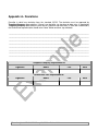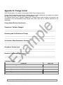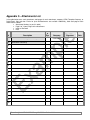
1
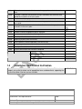
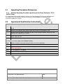
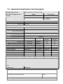
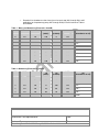
Template-Company Template-SN IQ / OQ Page 1 of 29 Liquid Chromatograph Flexar Analytical / FX-10 UHPLC Pumps Installation Qualification (IQ) and Operational Qualification (OQ) Company Name: Template-Company Address: Template-Address Location, Room: Serial Number or System Name: Template-SN Protocol Number: Template-Protocol Issue Date: 27 May 2009 Date Tested: Valid if tested within 1 year of Issue Date Recertification Period Recommended at 12 Months Recertification Due Date: Release History Part Number Release Publication Date 09234069 D June 2009 Any comments about the documentation for this product should be addressed to: User Assistance PerkinElmer Global Technical Support PerkinElmer LAS (UK) Ltd M/S 215 Chalfont Road 710 Bridgeport Avenue Seer Green Shelton Beaconsfield Connecticut 06484-4794 Bucks HP9 2FX U.S.A. United Kingdom Flexar Analytical / FX-10 UHPLC Pumps IQ/OQ Rev. D June 2009 Template-Company Template-SN IQ / OQ Page 2 of 29 Table of Contents Introduction ................................................................................................................................... 3 Objective........................................................................................................................................ 3 Protocol Documentation............................................................................................................... 4 Error Code Abbreviation, Definition, and Making Correction .................................................... 6 Approval Page............................................................................................................................... 7 Preliminary Protocol Approval ..................................................................................................... 7 Final Report Approval ................................................................................................................. 7 Part I – Installation Qualification.................................................................................................. 9 1.1 System Summary .............................................................................................................. 10 1.1.1 1.1.2 1.1.3 1.1.4 1.1.5 Instrument Identification......................................................................................................... 10 Specifications ........................................................................................................................ 10 Location Requirements.......................................................................................................... 10 Maintenance and Troubleshooting ......................................................................................... 10 Hazards and Safety Precautions............................................................................................ 10 1.2 Documentation .................................................................................................................. 11 1.2.1 1.2.2 1.2.3 Equipment Manual................................................................................................................. 11 Purchase Order Certification.................................................................................................. 11 PerkinElmer Service Engineer Training.................................................................................. 11 1.3 Installation Qualification..................................................................................................... 11 1.4 Installation Qualification Verification .................................................................................. 12 Part II – Operational Qualification .............................................................................................. 13 2.1 2.2 2.3 2.4 Operating Procedure References ...................................................................................... 14 Operational Qualification Instruction .................................................................................. 14 Operational Qualification Test Description......................................................................... 15 Parameter Testing............................................................................................................. 17 2.4.1 Pressure Pulsations Test ....................................................................................................... 17 2.4.2 Analytical Pump (100 µL Piston) Flow Check @ 1mL/min...................................................... 18 2.4.3 Analytical Pump (100 µL Piston) Flow Check @ 3mL/min....................................................…...19 2.4.4 FX-10 UHPLC Pump (30 µL Piston) Flow Check @ 0.3mL/min…...............…………………….20 2.4.5 FX-10 UHPLC Pump (30 µL Piston) Flow Check@ 0.9mL/min.……………...………………….. 21 2.4.6 Analytical Pump Composition Accuracy Test……………………………………………………….. 23 2.5 Operational Qualification Verification…………………………………………………………… 24 Part III – Appendices................................................................................................................... 25 Appendix A– Deviations ............................................................................................................ 26 Appendix B– Change Control.................................................................................................... 27 Appendix C– Attachments List .................................................................................................. 28 Appendix D- Document History ................................................................................................. 29 Flexar Analytical / FX-10 UHPLC Pumps IQ/OQ Rev. D June 2009 Template-Company Template-SN IQ / OQ Page 3 of 29 Introduction Objective The objective of this document is to detail the environmental and facilities requirements necessary for proper installation and operation of the Flexar Analytical / / FX-10 UHPLC Pump. The completed process demonstrates that the equipment meets the vendor-developed standards of operation and safety, and performs the functions specified by the manufacturer. Scope and Responsibility PerkinElmer is responsible for providing trained personnel, the IQ/OQ elements outlined in this plan and verifying that these elements are fully executed and documented. Template-Company is responsible for accepting the terms of this plan and providing the facility with all environmental requirements for the proper installation of the Flexar Analytical / / FX-10 UHPLC Pump. Template-Company is responsible for providing personnel and assistance to PerkinElmer for implementing the IQ/OQ outlined in this document. Warranty Period and Service Full details of PerkinElmer’s instrument warranty have previously been provided with quotations, order acknowledgements and invoices. PerkinElmer’s instrument warranty covers all parts and labor, but excludes consumable materials. Exceptions may apply to instruments purchased used. Contact your PerkinElmer service provider for a service plan which may be purchased to extend coverage beyond warranty. PerkinElmer recommends contracting regular preventive maintenance. Over time, failure to perform the recommended preventive maintenance may reduce the reliability of some systems. Need to Re-Qualify The instrument may need to qualified again following modifications made to the original configuration or if the instrument is serviced or moved. Notices Except as specifically set forth in its terms and conditions of sale, PerkinElmer makes no warranty of any kind with regard to this document, including, but not limited to, the implied warranties of merchantability and fitness for a particular purpose. PerkinElmer shall not be liable for incidental or consequential damages in connection with the furnishing or use of this document. Copyright Information This document contains proprietary information that is protected by copyright. All rights are reserved. No part of this publication may be reproduced in any form whatsoever or translated into any language without the prior, written permission of PerkinElmer, Inc. Copyright © 2009 PerkinElmer, Inc. Trademarks Registered names, trademarks, etc. used in this document, even when not specifically marked as such, are protected by law. PerkinElmer is a registered trademark of PerkinElmer, Inc. All other trademarks and registered trademarks not owned by PerkinElmer, Inc. or its subsidiaries that are depicted herein are the property of their respective owners. Flexar Analytical / FX-10 UHPLC Pumps IQ/OQ Rev. D June 2009 Template-Company Template-SN IQ / OQ Page 4 of 29 Protocol Documentation Documentation protocol may be superseded by customer SOP Writing Instruments All writing will be done with a black or blue ink pen. Signatures A signature of each party involved with the ownership, management, testing, and quality assurance of each instrument will be required before testing will proceed and for final approval at completion. On any page where a written entry is made, or data is gathered by a PerkinElmer representative, that page must be signed and dated by the PerkinElmer representative. Up to three signature entries are provided each for Customer and PerkinElmer on the Preliminary Report Approval Page and Final Approval Page. If any signature lines are unused, draw a single diagonal line filling the Signature area and then write initials and date next to the line. All signatures will be the signer’s full legal name as legibly as can be written and dated. Initials At any point when initials are to be used, they will contain at least two of the initials and include a date. Date Dates will be given in the format of DD-MMM-YYYY. If a month or date is only one digit, a zero will be employed to maintain the two-digit format for each entry. Error Codes When an error is corrected, a single horizontal line through the error will be used. The line will then be initialed and dated along with an error code from the list found in the protocol. Spaces For columns where the protocol is asking whether something has been verified, a “Yes” will be written. If not, a “No” will be written and an explanation will be stated in the Comments section. A check mark or “N” is unacceptable. “NA” may be used where the verification was not applicable. Pass/Fail For areas where the protocol requires a “Pass/Fail”, the words “Pass” or “Fail” will be written in. If the instrument passes, Pass will be entered. If the instrument fails, Fail will be entered. Visual Inspections All visual inspections will be filled out with a word that indicates the physical condition being observed. If no damage is observed, use the word “None” if no damage is present. If damage is observed, write a description of the damage observed. This will apply to any visual inspections. Calibration/Expiration dates MM/YY format will be used to denote calibration and reagent expiration dates. The instrument or reagent is valid until the last day of the month noted. Temperature All temperatures will be given in the unit of Celsius (°C) Blank Areas If there are no comments for a “Comments” section, “None” is written and the rest of the lines are left blank. If a section is not applicable, such as an alarm function, “NA” is sufficient. Flexar Analytical / FX-10 UHPLC Pumps IQ/OQ Rev. D June 2009 Template-Company Template-SN IQ / OQ Page 5 of 29 Once an entry has been made (other than “None”) any remaining space in the Comments (either single or multiple blank lines) requires a single diagonal line filling the area, along with initials and date next to the line. EXCEPTION: DO NOT cross out blank lines on the “Error Code Abbreviation, Definition and Making Corrections” page. These pages or sections are either copied for future documentation needs or provide space to maintain records into the future. Acceptance Criteria All tests must include values for acceptance criteria and the results of that test must be included. Precision and Accuracy Measurements The following areas of precision and accuracy will be noted on a per-test basis. All instrument precision values (when available) will be noted within the OQ document. All data entered into the OQ document will reflect these values. For example: If a precision value of four significant digits is supplied for a test by the manufacturer, then all four digits will be entered with the last digit being rounded down if the fifth digit is below 5, rounded up if above 5, and rounded up if fifth digit is 5. Failure Mode Responses If a test result is determined to be outside of the precision parameters set forth by manufacturer of instrument, it will be discussed with the customer first and if agreed both by customer and PerkinElmer then it will be repeated a second time to confirm the result. If the second result fails, the instrument owner will be contacted to discuss a reasonable course of action. If however, the second test passes, a note will be made as to the reason for the primary failure and the second test data will be used. Test -> Fail -> Repeat -> PASS -> Report 2nd result Deviation Deviations are events that are a departure from the specific protocol procedures as they were approved. Deviations to the plan are permitted if those deviations are clearly detailed, approved by all parties and entered in Appendix - Deviations Change Control Change control procedures are in place to maintain the validation process after modifications are made to the original configuration. Any changes to the hardware, firmware or software of a validated system must be clearly specified and the validation confirmed and recorded. 1. A blank Change Control form is located in Appendix C. Consider making photocopies when blank. 2. If used, insert a completed Change Control Form and its associated data as an Attachment. Flexar Analytical / FX-10 UHPLC Pumps IQ/OQ Rev. D June 2009 Template-Company Template-SN IQ / OQ Page 6 of 29 Error Code Abbreviation, Definition, and Making Correction The error code abbreviation and definition list below is provided for clients and reviewers to make necessary entries and corrections after the document has been approved. PerkinElmer technical staff and reviewers make all necessary efforts to ensure that this document and related attachments are free of errors and mistakes. However, some typographical, formatting, and inadvertently erroneous entries may exist within the document that can be corrected by client(s). Once an error is found, (1) simply strike the erroneous word or entry with a black pen, (2) enter the correct word or entry above the erroneous word or entry, (3) enter the code (for example; IE for incorrect entry), and (4) then initial and date. Space is also provided to create new codes or to enter the codes used and recommended by your compliance department. CE IE IM IO IR LE Calculation Error Incorrect Entry Instrument Malfunction Inadvertently Omitted Instrument Recalibrated Late Entry (of initials or date) NA SE TE TYP WD WO Not Applicable Spelling Error Transcription Error Typographical Error Wrong Date Entered Writeover Additional Codes Code Definition Flexar Analytical / FX-10 UHPLC Pumps IQ/OQ Rev. D June 2009 Initials Date Template-Company Template-SN IQ / OQ Page 7 of 29 Approval Page Preliminary Protocol Approval This is to certify that the Installation Qualification and Operational Qualifications procedures for the Flexar Analytical / / FX-10 UHPLC Pump Serial number Template-SN have been reviewed and both PerkinElmer LAS and Template-Company have agreed to proceed with the procedures described in this document. Template-Company Signature Name Title Date Title Date PerkinElmer LAS Signature Name Final Approval This is to certify that the Installation Qualification and Operational Qualifications procedures for the Flexar Analytical / / FX-10 UHPLC Pump Serial number Template-SN have been performed and the configuration installed meets [ ] does not meet [ ] the procedures and specifications described in this document. Template-Company Signature Name Title Date Title Date PerkinElmer LAS Signature Name Flexar Analytical / FX-10 UHPLC Pumps IQ/OQ Rev. D June 2009 Template-Company Template-SN IQ / OQ Page 8 of 29 This page intentionally blank Flexar Analytical / FX-10 UHPLC Pumps IQ/OQ Rev. D June 2009 Template-Company Template-SN IQ / OQ Page 9 of 29 Part I – Installation Qualification Flexar Analytical / FX-10 UHPLC Pumps IQ/OQ Rev. D June 2009 1.1 System Summary 1.1.1 Instrument Identification Manufacturer PerkinElmer Model Flexar Analytical / FX-10 UHPLC Pump Equipment Serial # Template-SN Firmware Version Instrument Control Software Version Model options, circle as applicable 1.1.2 Isocratic / Binary / Quaternary / FX-10 Specifications Refer to respective documents for specifications like Voltage requirements, Line Frequency, Power Consumption, Temperature, Relative Humidity, etc. Refer to respective documents for minimum PC requirements. 1.1.3 Location Requirements Refer to respective documents for specific requirements for the location of the instrument. Requirements are typically, space (actual size, bench space and weight requirements especially if heavy), environment, power supply, gas supply, etc., and any other needs for the safe and consistent operation of the instrument. 1.1.4 Maintenance and Troubleshooting Routine maintenance can be performed by a trained analyst using the instructions found in the respective documents for maintenance and troubleshooting. PerkinElmer has trained service representatives, who perform other planned maintenance service annually or as required. Departmental Standard Operating Procedures (SOPs) shall also be consulted to implement and document the necessary repairs. 1.1.5 Hazards and Safety Precautions Refer to respective documents for the safety summary outlines and explanation. Comments: PerkinElmer LAS Representative: Date: Reviewed By: Date: Flexar Analytical / FX-10 UHPLC Pumps IQ/OQ Rev. D June 2009 1.2 Documentation 1.2.1 Equipment Manual Part No. Title Flexar Analytical / FX-10 UHPLC Pump User’s Guide 1.2.2 Purchase Order Certification The Flexar Analytical / FX-10 UHPLC Pump Template-SN is in compliance with the specifications of the purchase order. Purchase Order Number 1.2.3 Template-PO PerkinElmer Service Engineer Training Persons authorized by PerkinElmer LAS to perform validations have been properly trained. Training is documented, and a certificate is issued by PerkinElmer LAS to that effect. See Attachment #1 for PerkinElmer LAS Training Certificate. 1.3 Installation Qualification Verify the following list and mark as appropriate: Description Verified 1.3.1 The working environment is suitable with reference to the appropriate section in the user’s manual 1.3.2 The correct basic equipment has been provided in accordance with the purchase order 1.3.3 The packaging is undamaged 1.3.4 The instrument, PC and other supplied equipment are undamaged 1.3.5 Users Guide is identified 1.3.6 Manufacturer’s specifications included in manual 1.3.7 The power requirement settings of the instrument, PC etc., are compatible with those of the working environment. Note: It is the responsibility of Template-Company to ensure proper voltage / current / frequency of the electrical line supplied for operating the Flexar Analytical / FX-10 UHPLC Pump. 1.3.8 Adequate room for ventilation and servicing the equipment Comments: PerkinElmer LAS Representative: Date: Reviewed By: Date: Flexar Analytical / FX-10 UHPLC Pumps IQ/OQ Rev. D June 2009 1.3.9 PC’s requirements are met with reference to the appropriate section in the user’s guide. 1.3.10 Instrument is identified, connected and set up in accordance with reference to the appropriate instructions in the user’s guide. 1.3.11 Adequate electricity supply available and unit is grounded 1.3.12 Software installed on the PC with reference to the appropriate instructions in the user’s guide. 1.3.13 Necessary components/accessories installed with reference to the appropriate instructions in the user’s guide. 1.3.14 Firmware verification 1.3.15 Software installed and appropriate panels displayed: 1.3.16 Instrument control software installed if applicable 1.3.17 Data Acquisition Software installed 1.3.18 Operating System (name and version) 1.3.19 Other Software installed if applicable (name and version) 1.3.20 Start-up diagnostics run to completion (instrument initialized) 1.3.21 Warranty and available services explained 1.3.22 System Familiarization and Orientation Completed 1.3.23 List Attendees: 1.4 Installation Qualification Verification The Flexar Analytical / FX-10 UHPLC Pump, Serial Number Template-SN, has been properly set up and installed, and all appropriate forms and documents supporting the system have been filled out and are available. Comments: PerkinElmer LAS Representative: Date: Reviewed By: Date: Flexar Analytical / FX-10 UHPLC Pumps IQ/OQ Rev. D June 2009 Verified: Part II – Operational Qualification Flexar Analytical / FX-10 UHPLC Pumps IQ/OQ Rev. D June 2009 2.1 Operating Procedure References 2.1.1 Standard Operating Procedures pertaining to the Flexar Analytical / FX-10 UHPLC Pump It is responsibility of the customer to follow a SOP for use of the equipment to ensure consistent operations. The customer SOP may be written after the Qualification and can be added as an attachment after PerkinElmer completes this IQ/OQ. 2.2 Operational Qualification Instruction The following instructions apply to the Operational Qualification Test Description 2.2.1 Record Model (or Part Number) and Serial Number of any accessories or components not covered in the OQ 2.2.2 Record the Serial Number and Calibration Date for each item of Test Equipment used. 2.2.3 Record the Batch/Lot Number and Expiration Date of each Standard, Reagent and Solvent used, including those supplied by the customer. 2.2.4 Label all solutions prepared at customer site in accordance with the customer requirements (date, content, expires by, etc) 2.2.5 Provide the Standard certificates as Attachments. The following instructions apply to the Parameter Testing 2.2.6 Conduct Parameter Testing and record test data, Pass/Fail and Comments. 2.2.7 Verify the completed OQ in Section 2.5 2.2.8 Sign, date and number attachments of all recordings or printouts made during the test procedure (ex. settings, spectrograms). 2.2.9 Fill in All Appendices, as required. 2.2.10 Complete and sign off the Final Approval 2.2.11 Complete and affix an IQ/OQ Certification Sticker to the instrument. Comments: PerkinElmer LAS Representative: Date: Reviewed By: Date: Flexar Analytical / FX-10 UHPLC Pump IQ/OQ Rev. D June 2009 2.3 Operational Qualification Test Description Configurations Covered Flexar Analytical/ FX-10 UHPLC Pump Model Accessories/Components not covered Serial Number Estimated Certificate Testing Time Pre-test Stabilization Testing Time N/A 2.0 Hours Materials Required Documentation Part Number Pump Users Manual (Not needed for testing. Reference only) Pump Service Manual (Not needed for testing. Reference only IQ/OQ Certification Sticker Test Equipment 09934512 Manufacturer Model Serial Number Calibration Due Date Restrictor Coil PerkinElmer 02540843 N/A N/A 1000 PSI Back Pressure Regulator PerkinElmer N2910381 N/A N/A Batch/Lot Expiration Calibrated Scale or Balance Calibrated Timing Device Customer Supplied Manufacturer H2O Part Number N/A N/A Acetone All solutions prepared at customer site must be labeled in accordance with the customer requirements Tests Name of Test Description Comments: PerkinElmer LAS Representative: Date: Reviewed By: Date: Flexar Analytical / FX-10 UHPLC Pump IQ/OQ Rev. D June 2009 Pressure Pulsations Flow Accuracy Pulsations (PSI) at 1 ml/min solvent flow and 1000 PSI backpressure (approx) For Analytical pumps, solvent flow as measured at 1ml and 3ml per minute. For the FX-10 UHPLC pumps, solvent flow as measured at 0.3ml and 0.9ml per minute. Compositional Accuracy For Binary / Quaternary Analytical pumps, accuracy as measured by relative UV absorbance (265 nm) at programmed proportions of 0.2% Acetone/Water and Water alone. PerkinElmer assumes no responsibility for test results. 2.4 Parameter Testing: 2.4.1 Pressure Pulsations Test Test Conditions Comments: PerkinElmer LAS Representative: Date: Reviewed By: Date: Flexar Analytical / FX-10 UHPLC Pump IQ/OQ Rev. D June 2009 The Pressure Pulsations Test is to verify that the output flow fluctuations are within specification. The specification for this test to pass is 2 % peak-to-peak of the running pressure at which the test is run. Test Prerequisites • Start the pump and let the pressure stabilize Test Steps • Connect the pump output to a restrictor coil or 1000 psi backpressure device. Set the pump flow rate to 1 mL/min. Running pressure for this test must be more than 500 psi. Adjust tubing length as required to obtain the required back pressure. • • Monitor the displayed pressure readout for 1 minute. Note the observed maximum and minimum pressures. • Using the numbers obtained determine: 1. The difference between maximum and minimum (Delta). 2. The value of the mid-point pressure (MP). 3. The 2% value of the midpoint pressure. This mid-point value is the pressure used to compute what the 2 % peak-to-peak error band should be. Example: Max 1020 psi, Min 1003 psi, Mid Point (MP Pressure) = 1011 psi. 2 % MP = MP * 0.02 = 20.22 psi Observed Delta = 17 psi Spec = Observed Delta <= 2 % MP 2.4.1 Test Results Parameter Specification Pressure Fluctuation Min Psi Max Psi Delta MP Pass/Fail < 2% of MP PSI 2.4.2 Analytical Pump (100 µL Piston) Flow Check @ 1 mL/min • Test Conditions Chromatographic Conditions: 100 % H2O 1 mL/min Test Prerequisites Comments: PerkinElmer LAS Representative: Date: Reviewed By: Date: Flexar Analytical / FX-10 UHPLC Pump IQ/OQ Rev. D June 2009 Comments It is important that the volume delivered is correct; the pressure during the delivery is not critical. There is a minimum pressure requirement of 350 psi for the check valves to operate properly. Test Steps • Connect the backpressure regulator to the output of the pump. This device will create the necessary back pressure on the pump check valves. • Purge the pump and fill the solvent line to be used for the test with water. • Zero the scale. Weigh the collection vessel on a calibrated scale or balance. • Take the collection vessel and go to the pump and set the pump flow for 1 mL/minute. • Start the pump. (Direct the initial flow of water off to waste until the pressure stabilizes. • When pressure stabilizes, direct the flow of water into the collection vessel and simultaneously start a stopwatch or other timing device. • Let the pump run for 5 minutes. • When 5 minutes has elapsed, remove the tube from above the collection vessel and insert it into the waste. • Weigh the collection vessel with the water. Subtract the weight of the collection vessel. • The remaining weight of the water should be 5 grams ±0.05 g (40.95 to 5.05 g) 1 mL/min * 5 min = 5 g (water weighs 1 gram per mL) • Divide the weight of the water by 5 to get the volume delivered in a 1 minute interval. • Record this number in the Test Result field of Flow Accuracy @ 1 mL/min portion of the IQOQ Test Certificate. Enter N/A if testing FX-10 UHPLC Pump. • 2.4.2 Test Results Parameter Analytical Pump (100 µL Piston) Accuracy: 1 mL/min Specification Test Result Pass/Fail Comments ± 1% of 1mL/min (00.99ml/min to 1.01ml/min) 2.4.3 Analytical Pump (100 µL Piston) Flow Check @ 3 mL/min Test Conditions Chromatographic Conditions: • 100 % H2O 3 mL/min Test Prerequisites It is important that the volume delivered is correct; the pressure during the delivery is not critical. There is a minimum pressure requirement of 350 psi for the check valves to operate properly. • Comments: PerkinElmer LAS Representative: Date: Reviewed By: Date: Flexar Analytical / FX-10 UHPLC Pump IQ/OQ Rev. D June 2009 Test Steps • Connect the backpressure regulator to the output of the pump. This device will create the necessary back pressure on the pump check valves. • Purge the pump and fill the line to be used for the test with water. • Zero the scale. Weigh the collection vessel on a calibrated scale or balance. • Take the collection vessel and go to the pump and set the pump flow for 3 mL/minute. • Start the pump. (Direct the initial flow of water off to waste until the pressure stabilizes. • When pressure stabilizes, direct the flow of water into the collection vessel and simultaneously start a stopwatch or other timing device. • Let the pump run for 5 minutes. • When 5 minutes has elapsed, remove the tube from above the collection vessel and insert it into the waste. • Weigh the collection vessel with the water. Subtract the weight of the collection vessel. • The remaining weight of the water should be 15 grams ±0.15 g (14.85 to 15.15 g) 3 mL/min * 5 min = 15 g (water weighs 1 gram per mL) • Divide the weight of the water by 5 to get the volume delivered in a 1 minute interval. • Record this number in the Test Result field of Flow Accuracy @ 3 mL/min portion of the IQOQ Test Certificate. Enter N/A if testing FX-10 UHPLC Pump. 2.4.3 Test Results Parameter Analytical Pump (100 µL Piston) Accuracy: 3 mL/min Specification Test Result Pass/Fail Comments ± 1% of 3mL/min (2.97ml/min to 3.03ml/min) 2.4.4 FX-10 UHPLC Pump (30 µL Piston) Flow Check @ 0.3 mL/min Test Conditions Chromatographic Conditions: • 100 % H2O 0.3 mL/min Test Prerequisites It is important that the volume delivered is correct; the pressure during the delivery is not critical. There is a minimum pressure requirement of 350 psi for the check valves to operate properly. • Comments: PerkinElmer LAS Representative: Date: Reviewed By: Date: Flexar Analytical / FX-10 UHPLC Pump IQ/OQ Rev. D June 2009 Test Steps • Connect the backpressure regulator to the output of the pump. This device will create the necessary back pressure on the pump check valves. • Purge the pump and fill the line to be used for the test with water. • Zero the scale. Weigh the collection vessel on a calibrated scale or balance. • Take the collection vessel and go to the pump and set the pump flow for 0.3 mL/minute. • Start the pump. (Direct the initial flow of water off to waste until the pressure stabilizes. • When pressure stabilizes, direct the flow of water into the collection vessel and simultaneously start a stopwatch or other timing device. • Let the pump run for 10 minutes. • When 10 minutes has elapsed, remove the tube from above the collection vessel and insert it into the waste. • Weigh the collection vessel with the water. Subtract the weight of the collection vessel. • The remaining weight of the water should be 3 grams ±0.03 g (2.97 to 3.03 g) 0.3 mL/min * 10 min = 3 g (water weighs 1 gram per mL) • Divide the weight of the water by 10 to get the volume delivered in a 1 minute interval. • Record this number in the Test Result field of Flow Accuracy @ 0.3 mL/min portion of the IQOQ Test Certificate. Enter N/A if testing Analytical Pump. 2.4.4 Test Results Parameter FX-10 Pump (30 µL Piston) Accuracy: 0.3 mL/min Specification Test Result Pass/Fail Comments ± 1% of 0.3mL/min (0.297ml/min to 0.303ml/min) 2.4.5 FX-10 UHPLC Pump (30 µL Piston) Flow Check @ 0.9 mL/min • Test Conditions Chromatographic Conditions: 100 % H2O 0.9 mL/min Test Prerequisites It is important that the volume delivered is correct; the pressure during the delivery is not critical. There is a minimum pressure requirement of 350 psi for the check valves to operate properly. • Test Steps • Connect the backpressure regulator to the output of the pump. This device will create the necessary back pressure on the pump check valves. • Comments: PerkinElmer LAS Representative: Date: Reviewed By: Date: Flexar Analytical / FX-10 UHPLC Pump IQ/OQ Rev. D June 2009 • • • • • • • • • • • Purge the pump and fill the line to be used for the test with water. Zero the scale. Weigh the collection vessel on a calibrated scale or balance. Take the collection vessel and go to the pump and set the pump flow for 0.9 mL/minute. Start the pump. (Direct the initial flow of water off to waste until the pressure stabilizes. When pressure stabilizes, direct the flow of water into the collection vessel and simultaneously start a stopwatch or other timing device. Let the pump run for 10minutes. When 10minutes has elapsed, remove the tube from above the collection vessel and insert it into the waste. Weigh the collection vessel with the water. Subtract the weight of the collection vessel . The remaining weight of the water should be 9 grams ±0.09 g (8.91 to 9.09g) 0.9 mL/min * 10 min = 9 g (water weighs 1 gram per mL) Divide the weight of the water by 10 to get the volume delivered in a 1 minute interval. Record this number in the Test Result field of Flow Accuracy @ 0.9 mL/min portion of the IQOQ Test Certificate. Enter N/A if testing Analytical Pump 2.4.5 Parameter FX-10 Pump (30 µL Piston) Accuracy: 0.9 mL/min Test Results Specification Test Result Pass/Fail ± 1% of 0.9 mL/min (0.891ml/min to 0.909ml/min) Comments: PerkinElmer LAS Representative: Date: Reviewed By: Date: Flexar Analytical / FX-10 UHPLC Pump IQ/OQ Rev. D June 2009 Comments 2.4.6 Binary / Quaternary Analytical Pump Composition Accuracy Test Test Prerequisites There is a minimum pressure requirement of 350 psi for the check valves to operate properly. To ensure the valves are operating and seating during the test PerkinElmer runs the test with the pressure approximately >500 psi. This is accomplished by using a length of 0.007” ID tubing or a backpressure device that will create the necessary back pressure on the check valves. Test Conditions The Composition Accuracy Test proves that the proportioning valves are operating correctly. This is accomplished by varying the amounts of solvent entering the pump through the proportioning valves. Using an acetone solution, which has an absorbance at 265 nm as one solvent, and water, which does not absorb at 265 nm we look at the absorbance of the resulting composition. By controlling or proportioning the amount of acetone in the water/acetone composition we can change the absorbance of the mobile phase composition. We do this by setting up a pump program to run through several different positions of the proportioning valves and measure the absorbance of the resultant mobile phase. Test Steps • Connect pump output directly to the backpressure regulator or other device (length of tubing for example) to create the necessary back pressure. • Fill reservoirs A (and C if testing a quaternary model) with HPLC grade water. • Pipette 1.0 mL of acetone into approximately 250 mL of HPLC-grade water. Dilute to 500 mL with HPLC grade water. Transfer the mobile phase to the labeled solvent reservoirs. Place the 0.2% acetone solution into reservoirs B (and D if testing a quaternary model). • Ensure that acetone solution is mixed well and degassed. • Bypass the column and autosampler and connect pump output directly to the backpressure regulator or other device (length of tubing for example) to create the necessary back pressure. • Connect the output of the back pressure device to the input of the detector flowcell. • Equilibrate and insure the binary or quaternary valves are operating correctly by running the pumps as follows: • Binary pump run 50/50 at 5mL/min for 10 minutes Quaternary pump run 25/25/25/25 at 5 mL/min for 10 minutes. • Observe the P-counts on the pump (CNFG/CAL/TEST/PCNT). The P-count value should fall typically in the range of 1300 + 50. Stability is important and the Range value should be typically less than 12. • Set the detector wavelength to 265 nm. • Set the flow rate to 5 mL/minute from reservoir A and allow the pressure to stabilize. Ensure the pump and baseline is stable at 5 mL/min. • Create and run the method in Tables 1 and 2 as appropriate with TotalChrom® or Chromera®, zeroing the detector at the end of step zero. Step 2 is the 100% reference. Flexar Analytical / FX-10 UHPLC Pumps IQ/OQ Rev. D June 2009 • Record mV or absorbance values from the run for each step (AU1 through AU6, and if applicable, for the quaternary pump, AU7 through AU10) in the AU column of Tables 1 and 2 below. Table 1 - Binary and Quaternary (Reservoirs A and B) STEP TIME FLOW %A (water) %B (acetone) CURV 0 5.0 5.0 100 0 0.0 1 1.0 5.0 100 0 0.0 2 3.0 5.0 0 100 0.0 AU1 = 3 3.0 5.0 10 90 0.0 AU2 = 4 3.0 5.0 49 51 0.0 AU3 = 5 3.0 5.0 51 49 0.0 AU4 = 6 3.0 5.0 90 10 0.0 AU5 = 7 5.0 5.0 100 0 0.0 AU6 = AU (absorbance or mV) Table 2 - Quaternary (Reservoirs C and D) STEP TIME FLOW %C (water) %D (acetone) CURV 0 5.0 5.0 100 0 0.0 1 1.0 5.0 100 0 0.0 2 3.0 5.0 0 100 0.0 AU7 = 3 3.0 5.0 10 90 0.0 AU8 = 4 3.0 5.0 90 10 0.0 AU9 = 5 5.0 5.0 100 0 0.0 AU10 = Comments: PerkinElmer LAS Representative: Date: Reviewed By: Date: Flexar Analytical / FX-10 UHPLC Pump IQ/OQ Rev. D June 2009 AU (absorbance or mV) 2.4.7 Test Results PARAMETER Composition Accuracy SPECIFICATION TEST RESULT PASS/FAIL Within ± 1.0% absolute @ 5 mL/min Channel A and B % Solvent B 10% 49% 51% 90% 49 / 51 Delta Range Channel C and D Between 1.5% and 2.5% % Solvent D 10% 90% Comments: 2.5 Operational Qualification Verification The Flexar Analytical / FX-10 UHPLC Pump, Serial Number Template-SN, operates and performs according to the stated Operational Qualification, and all appropriate forms and documents supporting the system have been filled out and are available. Comments: PerkinElmer LAS Representative: Date: Reviewed By: Date: Flexar Analytical / FX-10 UHPLC Pump IQ/OQ Rev. D June 2009 Verified: Part III – Appendices Flexar Analytical / FX-10 UHPLC Pump IQ/OQ Rev. D June 2009 Appendix A– Deviations Describe in detail any deviation from the standard IQ/OQ. The deviation must be approved by Template-Company representative. If there is no deviation, no signature or date entry is required by Template-Company representative (enter NA for signature and then date). If there are no deviations, the PerkinElmer representative should enter “None” below and then sign and date. ________________________________________________________________________________ ________________________________________________________________________________ ________________________________________________________________________________ ________________________________________________________________________________ ________________________________________________________________________________ ________________________________________________________________________________ ________________________________________________________________________________ ________________________________________________________________________________ Template-Company Representative Signature Name Title Date Title Date PerkinElmer LAS Representative Signature Name Flexar Analytical / FX-10 UHPLC Pump IQ/OQ Rev. D June 2009 Appendix B– Change Control Note: Create copies of this page, leaving original blank. Read instructions below. Change Control procedures maintain the validation processes after modifications are made to the original configuration (by OEM, Template-Company, or PerkinElmer LAS). The Change Control Form is located in Appendix B– Change Control and instructions are located in the Introduction. Insert the completed Change Control Form and its data into this validation document as an Attachment. Change Control Revision Attachment #: __ Component / Software Changed ________________________________________________________________________________________ ________________________________________________________________________________________ Reasoning and Justification for Change ________________________________________________________________________________________ ________________________________________________________________________________________ Verification of New Component / Software ________________________________________________________________________________________ ________________________________________________________________________________________ Acceptance Criteria Used ________________________________________________________________________________________ ________________________________________________________________________________________ Results of Verification (Attach original data) ________________________________________________________________________________________ ________________________________________________________________________________________ Validation Results Validation Pass/Fail Signature Date Performed By: Approved By: Flexar Analytical / FX-10 UHPLC Pump IQ/OQ Rev. D June 2009 Appendix C– Attachments List In the table below enter: each attachment; total pages for each attachment; company (OEM, Template-Company, or PerkinElmer). Sign and date. Entries for up to 20 Attachments are available. Additionally, label each page of each Attachment as follows: Attachment Number (as per this table) Page X of Y (total) Pages of the Attachment Initials of Reviewer Date # Description 1 PerkinElmer Service Engineer Training Certificate 2 Certificate of Conformity # Pgs Company PerkinElmer 3 4 5 6 7 8 9 10 11 12 13 14 15 16 17 18 19 20 Flexar Analytical / FX-10 UHPLC Pump IQ/OQ Rev. D June 2009 Signature Date Appendix D- Document History Revision Description of Change Page(s) Date A First release B Corrected math in instructions and typo in results 20 May 2009 C Corrected footers. All June 2009 D Corrected footers All June 2009 Flexar Analytical / FX-10 UHPLC Pump IQ/OQ Rev. D June 2009 May 2009 Appendix E- Spine Label for Instrument / System Log Book Cut out the label below and insert into the spine of the Instrument / System Log Book, then destroy the remainder of this page as it is no longer required. Instrument / System Log Book Template-Company Model Serial Number Protocol ID Flexar Analytical / FX-10 UHPLC Pump Template-SN TemplateProtocol Flexar Analytical / FX-10 UHPLC Pump IQ/OQ Rev. D June 2009