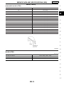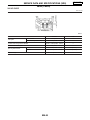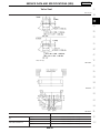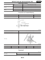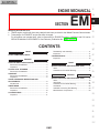
1
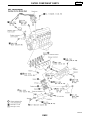
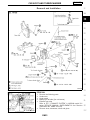
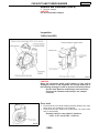
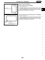
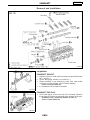
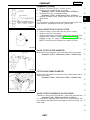
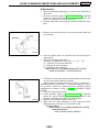
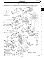
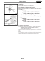
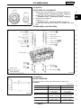
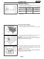
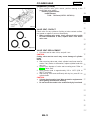
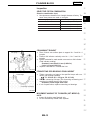
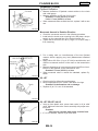
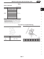
ENGINE MECHANICAL
GI
MA
SECTION
EM
MODIFICATION NOTICE:
I
I
TB45E engine models with three way catalyst have been provided for the Middle East and General areas.
Turbocharger for ZD30DDTi engine has been changed.
For information not included here, refer to information for ZD30DDTi engine in NISSAN model Y61 series
SERVICE MANUAL SUPPLEMENT-III 2nd Revision (Publication No. SM9E-Y61CG2).
LC
EC
FE
CL
CONTENTS
TB45E
OUTER COMPONENT PARTS .......................................2
ZD30DDTi
CATALYST AND TURBOCHARGER ..............................3
Removal and Installation .............................................3
Inspection.....................................................................4
OIL PAN & OIL STRAINER.............................................5
Removal and Installation .............................................5
CAMSHAFT .....................................................................6
Removal and Installation .............................................6
Inspection.....................................................................6
VALVE CLEARANCE INSPECTIONS AND
ADJUSTMENTS...............................................................8
Adjustments .................................................................8
TIMING GEAR .................................................................9
Removal and Installation .............................................9
Inspection...................................................................10
CYLINDER HEAD..........................................................11
Inspection...................................................................11
MT
Disassembly and Assembly.......................................11
Inspection...................................................................11
CYLINDER BLOCK .......................................................15
Inspection...................................................................15
AT
TF
TB45E
SERVICE DATA AND SPECIFICATIONS (SDS) ..........17
Valve ..........................................................................17
Camshaft and Camshaft Bushing..............................17
PD
FA
ZD30DDTi
SERVICE DATA AND SPECIFICATIONS (SDS) ..........18
Valve ..........................................................................18
Valve Seat..................................................................21
Camshaft and Camshaft Bearing ..............................22
Crankshaft..................................................................22
Available Connecting Rod Bearing............................23
Miscellaneous Components.......................................23
RA
BR
ST
RS
BT
HA
EL
SE
IDX
EM-1
OUTER COMPONENT PARTS
TB45E
SEM190H
EM-2
CATALYST AND TURBOCHARGER
ZD30DDTi
GI
Removal and Installation
MA
LC
EC
FE
CL
MT
AT
TF
PD
FA
RA
BR
ST
RS
SEM182H
BT
REMOVAL
1.
I
I
I
I
I
Remove the following parts.
Undercover
Under guard
Battery (on left side) (for cold areas)
Exhaust front tube
Refer to FE-7, “EXHAUST SYSTEM” in NISSAN model Y61
series SERVICE MANUAL SUPPLEMENT-III 2nd Revision
(Publication No. SM9E-Y61CG2).
Remove wires, harnesses, tubes and pipes.
HA
EL
SE
IDX
SEM296G
EM-3
CATALYST AND TURBOCHARGER
Removal and Installation (Cont’d)
ZD30DDTi
2. Remove catalyst.
CAUTION:
Do not disassemble catalyst.
Inspection
TURBOCHARGER
SEM184H
CAUTION:
When the compressor wheel, turbine wheel, or rotor shaft is
damaged, remove all the fragments and foreign matter left in
the following passages in order to prevent a secondary failure:
Suction side: Between turbocharger and intercooler
Exhaust side: Between turbocharger and catalytic
converter
Rotor shaft
I
I
Check that the rotor shaft rotates smoothly without any resistance when it is rotated by your fingertips.
Check that the rotor shaft is not loose when it is moved vertically or horizontally.
Standard value for rotor shaft oil clearance:
0.056 - 0.127 mm (0.0022 - 0.0050 in)
SEM298G
EM-4
OIL PAN & OIL STRAINER
ZD30DDTi
Removal and Installation
GI
INSTALLATION [OIL PAN (LOWER)]
I Install oil pan (Lower).
I Apply liquid gasket to inner sealing surface as shown in figure.
I Be sure liquid gasket is 3.5 to 4.5 mm (0.138 to 0.177 in).
I Attaching should be done within 5 minutes after coating.
Use Genuine Liquid Gasket or equivalent.
MA
LC
SEM345GA
INSTALLATION [OIL PAN (UPPER) AND OIL STRAINER]
I Install oil pan (Upper).
I Apply liquid gasket to inner sealing surface as shown in figure.
I Be sure liquid gasket is 3.5 to 4.5 mm (0.138 to 0.177 in).
I Attaching should be done within 5 minutes after coating.
Use Genuine Liquid Gasket or equivalent.
EC
FE
CL
MT
SEM347GA
AT
TF
PD
FA
RA
BR
ST
RS
BT
HA
EL
SE
IDX
EM-5
CAMSHAFT
ZD30DDTi
Removal and Installation
SEM189H
Inspection
CAMSHAFT RUNOUT
I
I
I
I
Prepare V-block on a flat surface and secure camshaft journals
No. 1 and No. 5.
Set the dial gauge vertically on journal No. 3.
Rotate camshaft in one direction by hand, then read needle
movement on dial indicator. (Total indicator reading)
Limit: 0.02 mm (0.0008 in)
If it exceeds the limit, replace camshaft.
PBIC0365E
CAMSHAFT END PLAY
I
Set the dial gauge to the front end of the camshaft. Measure
the end play by moving the camshaft in the direction of the axle.
Standard: 0.065 - 0.169 mm (0.0026 - 0.0067 in)
Limit: 0.2 mm (0.0079 in)
PBIC0366E
EM-6
CAMSHAFT
Inspection (Cont’d)
ZD30DDTi
I Replace the following parts if outside the limit.
a. Dimension A for camshaft (No. 2 journal)
Standard: 19.455 - 19.507 mm (0.7659 - 0.7680 in)
b. Dimension B for No. 2 camshaft bracket
Standard: 19.338 - 19.390 mm (0.7613 - 0.7634 in)
I Replace camshaft and/or cylinder head referring to the standards above.
NOTE:
It is impossible to replace only the camshaft bracket as the camshaft bracket is manufactured with the cylinder head.
GI
MA
LC
KBIA2318E
VISUAL INSPECTION OF VALVE LIFTER
I
I
I
Check if surface of valve lifter has any wear or cracks.
Replace valve lifter if necessary.
Select the thickness of the head so that valve clearance is the
standard when replacing. Refer to EM-46, “Inspection” in
NISSAN model Y61 series SERVICE MANUAL SUPPLEMENT-III 2nd Revision(Publication No. SM9E-Y61CG2).
EC
FE
CL
MT
KBIA2285E
VALVE LIFTER OUTER DIAMETER
Measure the outer diameter of the valve lifter with a micrometer.
Standard: 34.455 - 34.465 mm (1.3565 - 1.3569 in) dia.
AT
TF
PD
FA
RA
KBIA2286E
LIFTER GUIDE INNER DIAMETER
Measure the lifter guide inner diameter of the cylinder head with an
inside micrometer.
Standard: 34.495 - 34.515 mm (1.3581 - 1.3589 in) dia.
BR
ST
RS
BT
PBIC0367E
VALVE LIFTER CLEARANCE CALCULATIONS
Clearance = Lifter guide inner diameter − Valve lifter outer diameter
Standard: 0.030 - 0.060 mm (0.0012 - 0.0024 in)
If it exceeds the standard value, refer to the outer diameter and
bore diameter standard values and replace valve lifter and/or cylinder head.
HA
EL
SE
IDX
EM-7
VALVE CLEARANCE INSPECTIONS AND ADJUSTMENTS ZD30DDTi
Adjustments
I
Perform adjustment depending on selected head thickness of
valve lifter.
1. Remove camshaft. Refer to EM-41, “Removal” in NISSAN
model Y61 series SERVICE MANUAL SUPPLEMENT-III 2nd
Revision (Publication No. SM9E-Y61CG2).
2. Remove valve lifters at the locations that are outside the standard.
3. Measure the center thickness of the removed valve lifters with
a micrometer.
KBIA0057E
4. Use the equation below to calculate valve lifter thickness for
replacement.
I Valve lifter thickness calculation:
Thickness of replacement valve lifter = t1 + (C1 − C2)
t1 = Thickness of removed valve lifter
C1 = Measured valve clearance
C2 = Standard valve clearance:
When engine is cool [Approximately 20°C (68°F)]:
Intake and exhaust 0.35 mm (0.014 in)
I
KBIA2292E
Thickness of a new valve lifter can be identified by stamp marks
on the reverse side (inside the cylinder).
Stamp mark 535 indicates 5.35 mm (0.2106 in) in thickness.
Available thickness of valve lifter: 15 sizes with range 5.35 to 6.05
mm (0.2106 to 0.2382 in) in steps of 0.05 mm (0.0020 in) (when
manufactured at factory). Refer to EM-19, “AVAILABLE VALVE
LIFTER”.
5. Install the selected valve lifter.
6. Install camshaft. Refer to EM-44, “Installation” in NISSAN
model Y61 series SERVICE MANUAL SUPPLEMENT-III 2nd
Revision (Publication No. SM9E-Y61CG2), EM-44.
7. Manually turn crankshaft pulley a few turns.
8. Make sure that valve clearances for cold engine are within
specifications by referring to the specified values.
Valve clearance:
When engine is cool [Approximately 20°C (68°F)]
Intake and exhaust
0.30 - 0.40 mm (0.012 - 0.016 in)
EM-8
TIMING GEAR
ZD30DDTi
GI
Removal and Installation
2 idler gears are shown in this chapter. Idler gear (A) has scissors gear, and idler gear (B) does not.
MA
LC
EC
FE
CL
MT
AT
TF
PD
FA
RA
BR
ST
RS
BT
HA
EL
SE
IDX
SEM185H
EM-9
TIMING GEAR
ZD30DDTi
Inspection
BALANCER SHAFT OIL CLEARANCE
Outer diameter of balancer shaft journal
FEM039
Measure the outer diameter of the balancer shaft journal with a
micrometer.
Standard:
Front side
50.875 - 50.895 mm (2.0029 - 2.0037 in) dia.
Rear side
50.675 - 50.695 mm (1.9951 - 1.9959 in) dia.
Inner diameter of balancer shaft bearing
Measure the inner diameter of the balancer shaft bearing using a
bore gauge.
Standard:
Front side
50.955 - 50.980 mm (2.0061 - 2.0071 in) dia.
Rear side
50.755 - 50.780 mm (1.9982 - 1.9992 in) dia.
FEM040A
Oil clearance calculations
Oil clearance = Bearing inner diameter − Journal outer diameter
Standard: 0.060 - 0.105 mm (0.0024 - 0.0041 in)
Limit: 0.180 mm (0.0071 in)
Replace the balancer shaft and/or cylinder block if it exceeds the
limit.
NOTE:
It is impossible to replace only balancer shaft bearing because
balancer shaft bearing is manufactured with cylinder block.
EM-10
ZD30DDTi
CYLINDER HEAD
GI
Inspection
IDLER GEAR OIL CLEARANCE
I
Measure the inner diameter (d1) of idler gear shaft hole.
Standard: 26.000 - 26.020 mm (1.0236 - 1.0244 in)
Measure the outer diameter (d2) of idler shaft.
Standard: 25.967 - 25.980 mm (1.0223 - 1.0228 in)
Calculate gear clearance.
Clearance = d1 − d2
Standard: 0.020 - 0.053 mm (0.0008 - 0.0021 in)
Replace idler gear and/or idler shaft if it is outside of the standard.
I
I
FEM057
I
Disassembly and Assembly
MA
LC
EC
FE
CL
MT
AT
TF
PD
FA
RA
BR
PBIC1749E
Inspection
ST
RS
VALVE DIMENSION
Using micrometer, measure the dimensions of each part.
Standard
BT
Unit: mm (in)
Intake valve
113.5 (4.468)
3.8 - 4.2
(0.150 - 0.165)
1.5 (0.059)
6.962 - 6.977
(0.2741 - 0.2747)
31.9 - 32.1
(1.256 - 1.264)
45°00′ - 45°30′
a
b
PBIC0413E
c
d
D
α
EM-11
Exhaust valve
113.5 (4.468)
3.8 - 4.2
(0.150 - 0.165)
1.5 (0.059)
6.945 - 6.960
(0.2734 - 0.2740)
29.9 - 30.1
(1.177 - 1.185)
45°00′ - 45°30′
HA
EL
SE
IDX
ZD30DDTi
CYLINDER HEAD
Inspection (Cont’d)
VALVE GUIDE CLEARANCE
I
Calculate the clearance by measuring valve stem outer diameter and valve guide inner diameter.
Unit: mm (in)
SEM938C
I
Standard
Limit
Intake
0.023 - 0.056
(0.0009 - 0.0022)
0.18 (0.0071)
Exhaust
0.040 - 0.073
(0.0016 - 0.0029)
0.10 (0.0039)
If the measured value exceeds the limit, replace valve guide
and/or valve.
VALVE GUIDE REPLACEMENT
I There is no setup for oversized valve guide.
1. Heat cylinder head to 110 to 130°C (230 to 266°F) in oil bath.
FEM069
2. Using valve guide drift (multi-purpose tool: for 7.0 mm dia.), tap
valve guides out from the combustion chamber side.
CAUTION:
Cylinder head contains heat. Wear protective equipment to
avoid getting burned when working.
FEM070A
3. Heat cylinder head to 110 to 130°C (230 to 266°F) in oil bath.
4. Using valve guide drift (multi-purpose tool: for 7.0 mm dia.),
press fit valve guides from camshaft side, referring to the
dimension shown in the figure.
CAUTION:
Cylinder head contains heat. Wear protective equipment to
avoid getting burned when working.
FEM071
EM-12
CYLINDER HEAD
Inspection (Cont’d)
ZD30DDTi
5. Using suitable valve guide reamer, perform reaming to the
press-fitted valve guides.
Reaming specifications:
Intake/Exhaust
7.000 - 7.018 mm (0.2756 - 0.2763 in)
GI
MA
LC
FEM072A
VALVE SEAT CONTACT
Check valve for any evidence of pitting at valve contact surface,
and reseat or replace if worn out excessively.
I When repairing valve seats, check valve and valve guide
for wear beforehand. If worn, replace them. Then check
valve seat.
EC
FE
CL
MT
FEM073
VALVE SEAT REPLACEMENT
1. Cut valve seat to make it thin, and pull it out.
CAUTION:
Cutting valve seat too much may cause damage of cylinder
head.
NOTE:
I After removing valve seat, check cylinder head inner area for
cracks. If any cracks or deformation, replace cylinder head with
new one.
I Check inner diameter of valve seat mounting area. Refer to
EM-21, “Valve Seat”.
2. Heat cylinder head to approximately 110 to 130°C (230 to
266°F) in oil bath.
3. After cooling valve seats sufficiently with dry ice, press fit it to
cylinder head.
CAUTION:
I Cylinder head contains heat. Wear protective equipment to
avoid getting burned when working.
I Do not touch the cooled valve seats directly by bare hand.
AT
TF
PD
FA
RA
BR
ST
RS
BT
HA
EL
SE
IDX
EM-13
CYLINDER HEAD
Inspection (Cont’d)
4. Make sure that contacting status is satisfactory.
SEM191H
EM-14
ZD30DDTi
ZD30DDTi
CYLINDER BLOCK
GI
Inspection
SELECTIVE PISTON COMBINATION
Selective combination chart
I New pistons are classified into 4 weight classes at factory. The
same class pistons are used on a engine.
Weight grade symbol
Weight class g (oz)
E
615 - 620 (21.7 - 21.9)
F
620 - 625 (21.9 - 22.0)
G
625 - 630 (22.0 - 22.2)
H
630 - 635 (22.2 - 22.4)
MA
LC
EC
FE
CL
MT
CRANKSHAFT RUNOUT
I
I
I
I
Place V-block onto surface plate to support No. 2 and No. 4
journals.
Position dial indicator vertically onto No. 1, No. 3 and No. 5
journals.
Rotate crankshaft to read needle movement on dial indicator.
(Total indicator reading)
Standard: Less than 0.01 mm (0.0004 in)
Limit: 0.03 mm (0.0012 in)
Replace crankshaft if it exceeds the limit.
AT
TF
PD
FA
RA
PBIC1756E
CONNECTING ROD BEARING CRUSH HEIGHT
I
I
I
Tighten connecting rod caps to the specified torque with connecting rod bearings installed.
: 79 - 83 N⋅m (8.0 - 8.5 kg-m, 58 - 61 ft-lb)
Remove connecting rod caps. The connecting rod bearing end
must then be higher than the flat surface.
Standard: Crush height must exist.
If out of specification, replace connecting rod bearings.
BR
ST
RS
BT
PBIC1646E
MOVEMENT AMOUNT OF FLYWHEEL (M/T MODELS)
NOTE:
I Inspect for double mass flywheel only.
I Do not disassembly double mass flywheel.
HA
EL
SE
IDX
EM-15
CYLINDER BLOCK
Inspection (Cont’d)
ZD30DDTi
Flywheel Deflection
I
I
I
Measure deflection of flywheel contact surface to the clutch
with a dial gauge.
Measure deflection at 250 mm (9.84 in) dia.
Standard: 0.3 mm (0.012 in) or less
Limit: 0.7 mm (0.028 in) or less
When measured value exceeds the limit, replace it with a new
one.
PBIC1045E
Movement Amount in Rotation Direction
I Check the movement amount in the following procedure.
1. Install a bolt to clutch cover mounting hole, and place a torque
wrench on the extended line of the flywheel center line.
I Tighten bolt at a force of 9.8 N⋅m (1 kg-m, 87 in-lb) to keep it
from loosening.
2. Put a mating mark on circumferences of the two flywheel
masses without applying any load (Measurement standard
points).
3. Apply a force of 9.8 N⋅m (1 kg-m, 87 in-lb) in each direction, and
mark the movement amount on the mass on the transmission
side.
4. Measure dimensions of movement amounts A and B on circumference of the flywheel on the transmission side.
Standard: 5.9 mm (0.232 in) or less
I When measured value is outside the standard, replace flywheel.
PBIC2070E
OIL JET
I
I
I
Check nozzle for deformation and damage.
Blow compressed air from nozzle, and check for clogs.
Standard: No deformation and no damage
Replace oil jet if it is out of the standard.
PBIC0392E
OIL JET RELIEF VALVE
I
I
Using a clean plastic stick, press check valve in oil jet relief
valve. Make sure that valve moves smoothly with proper reaction force.
Standard:
Valve moves smoothly with proper reaction force.
If it is not satisfied, replace oil jet relief valve.
EMT0186D
EM-16
TB45E
SERVICE DATA AND SPECIFICATIONS (SDS)
GI
Valve
VALVE CLEARANCE
MA
Unit: mm (in)/°C (°F)
Cold
Hot (*1)
0.16 (0.006)/8 - 12 (46 - 54)
0.17 (0.007)/13 - 17 (55 - 63)
0.19 (0.007)/18 - 22 (64 - 72)
LC
0.20 (0.008)/23 - 27 (73 - 81)
Intake and
Exhaust
0.21 (0.008)/28 - 32 (82 - 90)
0.33 - 0.37
(0.013 - 0.015)
EC
0.23 (0.009)/33 - 37 (91 - 99)
0.24 (0.009)/38 - 42 (100 - 108)
FE
0.25 (0.010)/43 - 47 (109 - 117)
0.26 (0.010)/48 - 52 (118 - 126)
CL
Whenever valve clearances are adjusted to cold specifications:
I Based on the engine coolant temperature (the value indicated
by CONSULT-II) during valve clearance adjustment, select the
setting value from above table.
I Determine setting value based on radiator coolant temperature
if CONSULT-II could not be used.
*1: Reference data at engine coolant temperature 82°C (180°F)
MT
AT
Camshaft and Camshaft Bushing
Unit: mm (in)
Valve timing
TF
PD
FA
RA
EM671
TB45E
BR
Cam height “A”
EM120
Unit: degree
Intake
Exhaust
42.314 - 42.564
(1.6659 - 1.6757)
TB45E
a
b
c
d
e
f
236
236
−6
62
5
51
ST
RS
BT
HA
EL
SE
IDX
EM-17
ZD30DDTi
SERVICE DATA AND SPECIFICATIONS (SDS)
Valve
VALVE
Unit: mm (in)
PBIC0413E
Intake
Valve length “a”
113.5 (4.468)
Exhaust
Intake
“b”
3.8 - 4.2 (0.150 - 0.165)
Exhaust
Intake
Valve margin “c”
1.5 (0.059)
Exhaust
Intake
6.962 - 6.977 (0.2741 - 0.2747)
Exhaust
6.945 - 6.960 (0.2734 - 0.2740)
Valve stem diameter “d”
Intake
31.9 - 32.1 (1.256 - 1.264)
Exhaust
29.9 - 30.1 (1.177 - 1.185)
Valve head diameter “D”
Intake
Valve seat angle “α”
45°00′ - 45°30′
Exhaust
VALVE CLEARANCE
Unit: mm (in)
Cold*
Intake and exhaust
0.30 - 0.40 (0.012 - 0.016)
*: Approximately 20°C (68°F)
EM-18
SERVICE DATA AND SPECIFICATIONS (SDS)
Valve (Cont’d)
ZD30DDTi
GI
AVAILABLE VALVE LIFTER
Identification mark
Thickness
535
5.35 (0.2106)
540
5.40 (0.2126)
545
5.45 (0.2146)
550
5.50 (0.2165)
555
5.55 (0.2185)
560
5.60 (0.2205)
565
5.65 (0.2224)
570
5.70 (0.2244)
575
5.75 (0.2264)
580
5.80 (0.2283)
585
5.85 (0.2303)
590
5.90 (0.2323)
595
5.95 (0.2343)
600
6.00 (0.2362)
605
6.05 (0.2382)
MA
LC
EC
FE
CL
MT
AT
TF
PD
FA
KBIA2292E
VALVE LIFTER
Unit: mm (in)
Valve lifter outer diameter
34.455 - 34.465 (1.3565 - 1.3569)
Lifter guide inner diameter
34.495 - 34.515 (1.3581 - 1.3589)
Clearance between lifter and lifter guide
RA
BR
ST
0.030 - 0.060 (0.0012 - 0.0024)
RS
BT
HA
EL
SE
IDX
EM-19
ZD30DDTi
SERVICE DATA AND SPECIFICATIONS (SDS)
Valve (Cont’d)
VALVE GUIDE
Unit: mm (in)
FEM071
Standard
Outer diameter
Limit
11.023 - 11.034 (0.4340 - 0.4344)
—
7.000 - 7.018 (0.2756 - 0.2763)
—
10.996 - 10.975 (0.4329 - 0.4321)
—
0.027 - 0.059 (0.0011 - 0.0023)
—
Intake
0.023 - 0.056 (0.0009 - 0.0022)
0.18 (0.0071)
Exhaust
0.040 - 0.073 (0.0016 - 0.0029)
0.10 (0.0039)
12.8 - 13.2 (0.5309 - 0.5197)
—
Valve guide
Inner diameter (Finished size)
Cylinder head valve guide hole diameter
Interference fit of valve guide
Stem to guide clearance
Projection length
EM-20
SERVICE DATA AND SPECIFICATIONS (SDS)
ZD30DDTi
GI
Valve Seat
Unit: mm (in)
MA
LC
EC
FE
CL
MT
AT
TF
PBIC1726E
PD
FA
RA
BR
SEM373G
ST
RS
BT
HA
PBIC0421E
EL
Standard
Cylinder head seat recess diameter
(D)
Intake
33.000 - 33.015 (1.2992 - 1.2998)
Exhaust
31.495 - 31.510 (1.2400 - 1.2405)
Intake
0.050 - 0.078 (0.0020 - 0.0031)
Exhaust
0.040 - 0.066 (0.0016 - 0.0026)
Valve seat interference fit
EM-21
SE
IDX
ZD30DDTi
SERVICE DATA AND SPECIFICATIONS (SDS)
Valve Seat (Cont’d)
Intake
33.065 - 33.078 (1.3018 - 1.3023)
Exhaust
31.550 - 31.561 (1.2421 - 1.2426)
Valve seat outer diameter (d)
Intake
6.75 - 6.85 (0.2657 - 0.2697)
Exhaust
7.35 - 7.45 (0.2894 - 0.2933)
Height (h)
Intake
43.65 - 44.35 (1.7185 - 1.7461)
Exhaust
43.65 - 44.35 (1.7185 - 1.7461)
Depth (L)
Camshaft and Camshaft Bearing
Standard
Limit
—
0.02 (0.0008)
0.065 - 0.169 (0.0026 - 0.0067)
0.2 (0.008)
Camshaft runout [TIR*]
Camshaft end play
KBIA2318E
Camshaft (No. 2 journal) “A” dimension
19.455 - 19.507 (0.7659 - 0.7680)
No. 2 camshaft bracket “B” dimension
19.338 - 19.390 (0.7613 - 0.7634)
Valve timing
PBIC0517E
Unit: degree
a
b
c
d
e
232
220
6
34
50
*: Total indicator reading
Crankshaft
Unit: mm (in)
Standard
Less than 0.01 (0.0004)
Runout [TIR*]
Limit
0.03 (0.0012)
*: Total indicator reading
EM-22
ZD30DDTi
SERVICE DATA AND SPECIFICATIONS (SDS)
GI
Available Connecting Rod Bearing
BALANCER SHAFT BEARING
Unit: mm (in)
Front
50.875 - 50.895 (2.0029 - 2.0037)
Rear
50.675 - 50.695 (1.9951 - 1.9959)
Front
50.955 - 50.980 (2.0061 - 2.0071)
Rear
50.755 - 50.780 (1.9982 - 1.9992)
MA
Balancer shaft journal outer diameter
Balancer shaft bearing inner diameter
Standard
LC
0.060 - 0.105 (0.0024 - 0.0041)
Balancer shaft journal oil clearance
Limit
0.180 (0.0071)
EC
Miscellaneous Components
Unit: mm (in)
Standard
0.3 (0.012) or less
Flywheel deflection [TIR]*
Limit
FE
CL
0.7 (0.028)
Flywheel movement in rotation direction
5.9 (0.232) or less
*: Total indicator reading
MT
AT
TF
PD
FA
RA
BR
ST
RS
BT
HA
EL
SE
IDX
EM-23