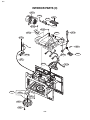
1
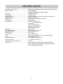
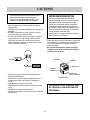
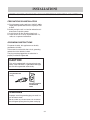
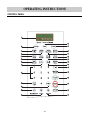
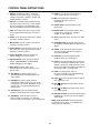
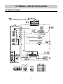
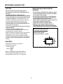
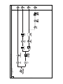
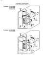
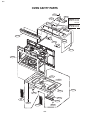
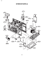
삼
정
흥
판
MODEL 721.80042
721.80049
721.80044
721.80043
721.81043
DIVISION 22
BASIC FIELD MANUAL
FOR
MICROWAVE OVEN
MODEL 721.80042700
721.80049700
721.80044700
721.80043700
721.81043700
June, 2007
CAUTION
SAFETY PRECAUTIONS
PRECAUTIONS TO BE OBSERVED BEFORE AND
DURING SERVICING TO AVOID POSSIBLE EXPOSURE
TO EXCESSIVE MICROWAVE ENERGY
a. Do not operate or allow the oven to be operated with the door open.
b. Make the following safety checks on all ovens to be serviced before activating the
magnetron or other microwave source, and make repairs as necessary; (1) Interlock
operation, (2) proper door closing, (3) seal and sealing surfaces (arcing, wear, and
other damage), (4) damage to or loosening of hinges and latches, (5) evidence of
dropping or abuse.
c. Before turning on microwave power for any service test or inspection within the
microwave generating compartments, check the magnetron, wave guide or
transmission line, and cavity for proper alignment, integrity, and connections.
d. Any defective or misadjusted components in the interlock, monitor, door seal, and
microwave generation and transmission systems shall be repaired, replaced, or
adjusted by procedures described in this manual before the oven is released to the
owner.
e. A Microwave leakage check to verify compliance with the Federal performance standard should
be performed on each oven prior to release to the owner.
• Proper operation of the microwave ovens requires that the magnetron be assembled to the
wave guide and cavity. Never operate the magnetron unless it is properly installed.
• Be sure that the magnetron gasket is properly installed around the dome of the tube whenever
installing the magnetron.
• Routine service safety procedures should be exercised at all times.
• Untrained personnel should not attempt service without a thorough review of the test
procedures and safety information contained in this manual.
FOREWORD
Read this Manual carefully. Failure to adhere to or observe the information in this Manual may result in exposing
yourself to the Microwave Energy normally contained within the oven cavity.
TABLE OF CONTENTS
(Page)
SAFETY PRECAUTIONS - - - - - - - - - - - - - - - - - - - - - - - - - - - - - - - - - - - - - - - - - - - - - - - - - - - - - - - - - - - - - - - - - - - - - - - - - - - - - - - - - - - - - - - - - - - - - - - - - - - - Inside front page
SPECIFICATIONS - - - - - - - - - - - - - - - - - - - - - - - - - - - - - - - - - - - - - - - - - - - - - - - - - - - - - - - - - - - - - - - - - - - - - - - - - - - - - - - - - - - - - - - - - - - - - - - - - - - - - - - - - - - - - - - - - - - - - - - - - - - - - - - - 1-1
CAUTIONS - - - - - - - - - - - - - - - - - - - - - - - - - - - - - - - - - - - - - - - - - - - - - - - - - - - - - - - - - - - - - - - - - - - - - - - - - - - - - - - - - - - - - - - - - - - - - - - - - - - - - - - - - - - - - - - - - - - - - - - - - - - - - - - - - - - - - - - - - - 2-1
INSTALLATIONS - - - - - - - - - - - - - - - - - - - - - - - - - - - - - - - - - - - - - - - - - - - - - - - - - - - - - - - - - - - - - - - - - - - - - - - - - - - - - - - - - - - - - - - - - - - - - - - - - - - - - - - - - - - - - - - - - - - - - - - - - - - - - - - - - - 3-1
OPERATING INSTRUCTIONS - - - - - - - - - - - - - - - - - - - - - - - - - - - - - - - - - - - - - - - - - - - - - - - - - - - - - - - - - - - - - - - - - - - - - - - - - - - - - - - - - - - - - - - - - - - - - - - - - - - - - - - - - - - - - - - - 4-1
CONTROL PANEL - - - - - - - - - - - - - - - - - - - - - - - - - - - - - - - - - - - - - - - - - - - - - - - - - - - - - - - - - - - - - - - - - - - - - - - - - - - - - - - - - - - - - - - - - - - - - - - - - - - - - - - - - - - - - - - - - - - - - - - - - 4-1
CONTROL PANEL INSTRUCTIONS - - - - - - - - - - - - - - - - - - - - - - - - - - - - - - - - - - - - - - - - - - - - - - - - - - - - - - - - - - - - - - - - - - - - - - - - - - - - - - - - - - - - - - - - - - - - - - - - 4-2
OVERALL CIRCUIT DIAGRAM - - - - - - - - - - - - - - - - - - - - - - - - - - - - - - - - - - - - - - - - - - - - - - - - - - - - - - - - - - - - - - - - - - - - - - - - - - - - - - - - - - - - - - - - - - - - - - - - - - - - - - - - - - - - - - - 5-1
SCHEMATIC DIAGRAM - - - - - - - - - - - - - - - - - - - - - - - - - - - - - - - - - - - - - - - - - - - - - - - - - - - - - - - - - - - - - - - - - - - - - - - - - - - - - - - - - - - - - - - - - - - - - - - - - - - - - - - - - - - - - - - - - 5-1
MATRIX CIRCUIT FOR TOUCH KEY BOARD - - - - - - - - - - - - - - - - - - - - - - - - - - - - - - - - - - - - - - - - - - - - - - - - - - - - - - - - - - - - - - - - - - - - - - - - - - - - - - - - - - - 5-2
GENERAL INFORMATION FOR SERVICE - - - - - - - - - - - - - - - - - - - - - - - - - - - - - - - - - - - - - - - - - - - - - - - - - - - - - - - - - - - - - - - - - - - - - - - - - - - - - - - - - - - - - - - - - - - - - - - 6-1
GENERAL PRECAUTIONS IN USE - - - - - - - - - - - - - - - - - - - - - - - - - - - - - - - - - - - - - - - - - - - - - - - - - - - - - - - - - - - - - - - - - - - - - - - - - - - - - - - - - - - - - - - - - - - - - - - - - 6-1
TRIAL OPERATION - - - - - - - - - - - - - - - - - - - - - - - - - - - - - - - - - - - - - - - - - - - - - - - - - - - - - - - - - - - - - - - - - - - - - - - - - - - - - - - - - - - - - - - - - - - - - - - - - - - - - - - - - - - - - - - - - - - - - - - 6-1
FEATURES AND SPECIFICATIONS FEATURES - - - - - - - - - - - - - - - - - - - - - - - - - - - - - - - - - - - - - - - - - - - - - - - - - - - - - - - - - - - - - - - - - - - - - - - - - - - - - - - 6-1
SERVICE INFORMATION - - - - - - - - - - - - - - - - - - - - - - - - - - - - - - - - - - - - - - - - - - - - - - - - - - - - - - - - - - - - - - - - - - - - - - - - - - - - - - - - - - - - - - - - - - - - - - - - - - - - - - - - - - - - - - - - - - - - - - 7-1
PRECAUTIONS AND REPAIR SERVICE TIPS - - - - - - - - - - - - - - - - - - - - - - - - - - - - - - - - - - - - - - - - - - - - - - - - - - - - - - - - - - - - - - - - - - - - - - - - - - - - - - - - - - - 7-1
MICROWAVE LEAKAGE TEST - - - - - - - - - - - - - - - - - - - - - - - - - - - - - - - - - - - - - - - - - - - - - - - - - - - - - - - - - - - - - - - - - - - - - - - - - - - - - - - - - - - - - - - - - - - - - - - - - - - - - - - 7-2
POWER OUTPUT MEASUREMENT - - - - - - - - - - - - - - - - - - - - - - - - - - - - - - - - - - - - - - - - - - - - - - - - - - - - - - - - - - - - - - - - - - - - - - - - - - - - - - - - - - - - - - - - - - - - - - - - 7-3
DISASSEMBLY INSTRUCTIONS - - - - - - - - - - - - - - - - - - - - - - - - - - - - - - - - - - - - - - - - - - - - - - - - - - - - - - - - - - - - - - - - - - - - - - - - - - - - - - - - - - - - - - - - - - - - - - - - - - - - - 7-4
INTERLOCK SYSTEM - - - - - - - - - - - - - - - - - - - - - - - - - - - - - - - - - - - - - - - - - - - - - - - - - - - - - - - - - - - - - - - - - - - - - - - - - - - - - - - - - - - - - - - - - - - - - - - - - - - - - - - - - - - - - - - - - - 7-12
INTERLOCK CONTINUITY TEST - - - - - - - - - - - - - - - - - - - - - - - - - - - - - - - - - - - - - - - - - - - - - - - - - - - - - - - - - - - - - - - - - - - - - - - - - - - - - - - - - - - - - - - - - - - - - - - - - - - 7-14
TEST AND CHECKOUT PROCEDURES AND TROUBLE SHOOTING - - - - - - - - - - - - - - - - - - - - - - - - - - - - - - - - - - - - - - - - - - - - - - - - - 7-15
A. TEST PROCEDURES - - - - - - - - - - - - - - - - - - - - - - - - - - - - - - - - - - - - - - - - - - - - - - - - - - - - - - - - - - - - - - - - - - - - - - - - - - - - - - - - - - - - - - - - - - - - - - - - - - - - - - - - 7-15
B. CHECKOUT PROCEDURES - - - - - - - - - - - - - - - - - - - - - - - - - - - - - - - - - - - - - - - - - - - - - - - - - - - - - - - - - - - - - - - - - - - - - - - - - - - - - - - - - - - - - - - - - - - - - - 7-18
C. TROUBLE SHOOTING - - - - - - - - - - - - - - - - - - - - - - - - - - - - - - - - - - - - - - - - - - - - - - - - - - - - - - - - - - - - - - - - - - - - - - - - - - - - - - - - - - - - - - - - - - - - - - - - - - - - - - 7-21
EXPLODED VIEW - - - - - - - - - - - - - - - - - - - - - - - - - - - - - - - - - - - - - - - - - - - - - - - - - - - - - - - - - - - - - - - - - - - - - - - - - - - - - - - - - - - - - - - - - - - - - - - - - - - - - - - - - - - - - - - - - - - - - - - - - - - - - - - - 8-1
PART REFERENCE LIST - - - - - - - - - - - - - - - - - - - - - - - - - - - - - - - - - - - - - - - - - - - - - - - - - - - - - - - - - - - - - - - - - - - - - - - - - - - - - - - - - - - - - - - - - - - - - - - - - - - - - - - - - - - - - - - - - - - - - 9-1
SPECIFICATIONS
Rated Power Consumption - - - - - - - - - - - - - - - - - - - - - - - - - - - - - - - - - - 1500W maximum (Microwave oven+Cook top lamps+Ventilation fan)
Microwave Output - - - - - - - - - - - - - - - - - - - - - - - - - - - - - - - - - - - - - - - - - - - - - - - - 1000W (IEC60705)
Adjustable 100W through 1000W, 10 steps
Frequency - - - - - - - - - - - - - - - - - - - - - - - - - - - - - - - - - - - - - - - - - - - - - - - - - - - - - - - - - 2450 MHz ± 50 MHz
Power Supply - - - - - - - - - - - - - - - - - - - - - - - - - - - - - - - - - - - - - - - - - - - - - - - - - - - 120 VAC, 60 Hz
Rated Current - - - - - - - - - - - - - - - - - - - - - - - - - - - - - - - - - - - - - - - - - - - - - - - - - - - 14 Amp. (Microwave oven+Cook top lamp+Ventilation fan)
Magnetron Cooling - - - - - - - - - - - - - - - - - - - - - - - - - - - - - - - - - - - - - - - - - - - - Forced Air Cooling
Rectification - - - - - - - - - - - - - - - - - - - - - - - - - - - - - - - - - - - - - - - - - - - - - - - - - - - - - - Rectification Voltage Double Half-Wave
Door Sealing - - - - - - - - - - - - - - - - - - - - - - - - - - - - - - - - - - - - - - - - - - - - - - - - - - - - - Choke System
Safety Devices - - - - - - - - - - - - - - - - - - - - - - - - - - - - - - - - - - - - - - - - - - - - - - - - - - Magnetron Thermal Fuse:
Open at 90°C ± 5°C
Fuse(20A)
Primary Interlock Switch
Secondary Interlock Switch
Interlock Monitor Switch
Magnetron - - - - - - - - - - - - - - - - - - - - - - - - - - - - - - - - - - - - - - - - - - - - - - - - - - - - - - - - 2M214-161GP
High Voltage Capacitor - - - - - - - - - - - - - - - - - - - - - - - - - - - - - - - - - - - - - - Capacitor: 1.0µF, 2.1 KV AC
High Voltage Diode - - - - - - - - - - - - - - - - - - - - - - - - - - - - - - - - - - - - - - - - - - - Diode; 350mA, 9.0 KV
Cook top Lamp - - - - - - - - - - - - - - - - - - - - - - - - - - - - - - - - - - - - - - - - - - - - - - - - - 125 V, 30 W
Cavity Lamp - - - - - - - - - - - - - - - - - - - - - - - - - - - - - - - - - - - - - - - - - - - - - - - - - - - - - 125 V, 30 W or 40 W
Timer - - - - - - - - - - - - - - - - - - - - - - - - - - - - - - - - - - - - - - - - - - - - - - - - - - - - - - - - - - - - - - - Digital, up to 99 mim. 99 sec. (in each cooking stage)
Tray - - - - - - - - - - - - - - - - - - - - - - - - - - - - - - - - - - - - - - - - - - - - - - - - - - - - - - - - - - - - - - - - - Tempered Safety Glass
Overall Dimensions - - - - - - - - - - - - - - - - - - - - - - - - - - - - - - - - - - - - - - - - - - - 2915/16"(W)x167/16"(H)x1511/16"(D)
Oven Cavity Size - - - - - - - - - - - - - - - - - - - - - - - - - - - - - - - - - - - - - - - - - - - - - - 219/16"(W)x91/4"(H)x141/8"(D)
Effective Capacity of Oven Cavity - - - - - - - - - - - - - - - - - - - - - - - 1.6 Cu.ft.
Accessories - - - - - - - - - - - - - - - - - - - - - - - - - - - - - - - - - - - - - - - - - - - - - - - - - - - - - - Owner’s Manual & Cooking Guide, Installation Manual,
Exhaust Adapter, Exhaust Damper, Mounting Kit and Two
Filters, Rotating Ring Assembly.
1-1
CAUTIONS
Unlike other appliances, the microwave oven is
high-voltage and high-current equipment.
Though it is free from danger in ordinary use,
extreme care should be taken during repair.
MICROWAVE RADIATION
Personnel should not be exposed to the
microwave energy which may radiate from the
magnetron or other microwave generating
device if it is improperly used or connection.
All input and output microwave connections,
waveguide, flange, and gasket must be secure
never operate the device without a microwave
energy absorbing load attached.
Never look into an open waveguide or antenna
while the device is energized.
• DO NOT operate on a 2-wire extension cord during
repair and use.
• NEVER TOUCH any oven components or wiring during
operation.
• BEFORE TOUCHING any parts of the oven, always
remove the power plug from the outlet.
• For about 30 seconds after the oven stops, an electric
charge remains in the high voltage capacitor. When
replacing or checking, you must discharge the high
voltage capacitor by shorting across the two terminals
with an insulated screwdriver.
• Proper operation of the microwave oven requires that
the magnetron be assembled to the waveguide and
cavity. Never operate the magnetron unless it is
properly installed.
• Be sure that the magnetron gasket is properly
installed around the dome of the tube whenever
installing the magnetron.
ANTENNA
Gasket
COOLING FIN
FILAMENT
TERMINALS
MAGNETRON
CHASSIS GROUND
• Remove your watches whenever working close to or
replacing the Magnetron.
• DO NOT touch any parts of the control panel circuit. A
resulting static electric discharge may damage this
P.C.B.
• NEVER operate the oven with no load.
• NEVER injure the door seal and front plate of the oven
cavity.
• NEVER put iron tools on the magnetron.
• NEVER put anything into the latch hole and the interlock
switches area.
MAGNETRON
THE OVEN IS TO BE SERVICED ONLY
BY PROPERLY QUALIFIED SERVICE
PERSONNEL.
2-1
INSTALLATIONS
BEFORE YOU BEGIN, READ THE FOLLOWING INSTRUCTIONS COMPLETELY AND CAREFULLY.
PRECAUTIONS ON INSTALLATION
A. Plug the power supply cord into a 120V AC, 60Hz,
single-phase power source with a capacity of 15A
or 20A.
B. Avoid placing the unit in a location where there is
direct heat or splashing water.
C. Install the unit on the mounting plate firmly.
D. Place the unit as far away as possible from TV,
radio, etc. to prevent interference.
GROUNDING INSTRUCTIONS
For personal safety, this appliance must be fully
grounded at all times.
In the event of an electrical short circuit, grounding
reduces the risk of electrical shock.
The plug must be plugged into an outlet that is
properly installed and grounded.
CAUTION
This unit is equipped with a 3-prong plug for your
safety. If the wall outlet is a grounded 3-hole type,
the unit will be grounded automatically.
Plug with Ground
Prong
Properly Polarized
and Grounded
Outlet
WARNING
Improper use of the grounding plug can result in a
risk of electric shock.
Do not, under any circumstances, cut or remove
the third ground prong from the power cord plug.
3-1
OPERATING INSTRUCTIONS
CONTROL PANEL
4-1
CONTROL PANEL INSTRUCTIONS
14. Soften. Touch this pad to soften utter,ice
cream, cream cheese, or frozen juice.
1. Display. The display includes a clock and
indicators to tell you time of day, cooking time
settings, cook powers, quantities, weights and
cooking functions selected.
15. Melt. Touch this pad to melt butter or
margarine, chocolate, cheese, or
marshmallows.
2. Popcorn. Touch this pad to pop popcorn with
the sensor feature. The oven ’s sensor will tell
the oven how long to cook depending on the
amount of humidity it detects from the popcorn.
16. Kitchen Timer. Touch this pad to set the
kitchen timer.
3. Pizza. Touch this pad to reheat one or several
slices of pizza without entering a cook time or
power.
17. Number Pads. Touch number pads to enter
cooking times, cook powers, quantities,
weights, or food categories.
4. Potato. Touch this pad to cook potatoes without
entering a cook time or power.
18. Clock. Touch this pad to enter the correct time
of day.
5. Dinner Plate. Touch this pad to cook without
entering a cook time or power.
19. Turntable On/Off. Touch this pad to turn off
the turntable. “T/TABLE OFF” will appear in the
display.
6. Frozen Entree. Touch this pad to cook a 10 - to
20 - ounce (284 to 567 g) frozen entree without
entering a cook time or power.
20. START. Touch this pad to start a function.If
you open the door after the oven begins to
cook, retouch START.
7. Frozen Vegetable. Touch this pad to cook
without entering a cook time or power.
21. Cook Time. Touch this pad followed by
Number Pads to set a cooking time.
8. Express Defrost. Touch this pad to express
defrost. “GROUND BEEF 1.0 LBS TOUCH
START” will appear in the display.
22. Power. Touch this pad after the cook time has
been set, followed by a Number Pad to set the
amount of microwave energy released to cook
the food. The higher the number, the higher the
microwave power or “cooking speed.”
9. Auto Cook. Touch this pad to cook
microwavable foods without entering a cook
time or power.
23. STOP. Touch this pad to erase an
incorrect command, cancel a program during
cooking, or to clear the Display.
10. Auto Reheat. Touch this pad to reheat
microwavable foods without entering a cook
time or power.
24. Light (
). Touch this pad to turn the light on
high, night (low) or off.
11. Hold Warm. Touch this pad to keep hot,
cooked foods safely warm in your oven for up
to 99 minutes, 99 seconds. Hold Warm can be
used by itself, or it can automatically follow a
cooking cycle.
25. Fan (
) On/Off. Touch this pad to turn the
fan on or off.
26. Fan (
) 5 Speed. Touch this pad to choose
one of 5 fan speeds.
12. Auto Defrost. Touch this pad followed by
Number Pads to thaw frozen meat by weight.
27. Auto Off Fan timer. Touch this pad followed by
Number pad to set a time for the fan stopping
automatically
13. Add Minute. Touch this pad to cook for 1
minute at 100% cook power, or to add extra
minutes at the set cook power to your cooking cycle.
NOTE: If you try to enter incorrect instructions,
you will not hear any tones. Touch STOP/Clear
and re-enter the instructions.
4-2
OVERALL CIRCUIT DIAGRAM
SCHEMATIC DIAGRAM
5-1
MATRIX CIRCUIT FOR TOUCH KEY BOARD
5-2
GENERAL INFORMATION FOR SERVICE
GENERAL PRECAUTIONS IN USE
FEATURES AND SPECIFICATIONS
FEATURES
A. Never operate the unit when it is empty.
Operating the oven with no load may shorten the
life of the magnetron. Whenever cooking dry foods
(dried fish, bread, etc.) or a small amount of food,
be sure to put a glass of water into the cooking
compartment. The glass turntable may become hot
after operating, be careful when touching it.
B. Aluminum foil should be avoided because it will
disrupt cooking and may cause arcing. However,
small pieces may be used to cover some parts of
food to slow the cooking. Any aluminum foil used
should never be closer than 2.5 cm to any side wall
of the oven.
A. The safety systems incorporated in this model are:
(1) Primary interlock switch
(2) Secondary interlock switch
(3) Interlock monitor switch
(4) Choke system
(5) Magnetron thermostat
(6) Oven cavity thermostat
(Note: This thermostat located on the oven
cavity will open and stop the unit from operation
only if a high temperature is reached, such as,
a fire created by overcooking food.)
B. Any one of 10 power output levels ranging 100W to
1000W can be selected by the touch control and
electronic computer system.
TRIAL OPERATION
After installation, the following sequences and results
should be checked carefully.
A. Put a container filled with water (about 1 liter) into
the oven, and close the door tightly.
B. Set cooking time for 10 minutes by touching “1”
and then “0” three times. “1, 0, 0, 0” appears in
the display window.
C. Touch the START key.
Make sure the cavity light comes on. The unit will
begin cooking and the display window will show the
time counting down by seconds.
D. After about 5 minutes, make sure the primary
interlock switch, the secondary interlock switch and
the interlock monitor switch operate properly by
opening and closing the door several times. Touch
the START key each time the door is closed.
E. Continue operating the unit. Two short and a long
beep sound signal is heard when the time is up.
The unit will shut off automatically.
F. Confirm the water is hot.
G. Finally, measure the output power according to
“POWER OUTPUT MEASUREMENT” on
page 7-3.
6-1
SERVICE INFORMATION
PRECAUTIONS AND REPAIR SERVICE TIPS
PRELIMINARY
(3) Do not operate the unit until it is completely
repaired, if any of the following conditions exist.
The unit must not be operated.
(a) The door does not close firmly.
(b) The hinge is broken.
(c) The door seal is damaged.
(d) The door is bent or warped, or there is any
other visible damage on the unit that may
cause microwave energy leakage.
NOTE: Always keep the seal clean.
(e) Make sure that there are no defective parts
in the interlock mechanism.
(f) Make sure that there are no detective parts
in the microwave generating and transmission
assembly (especially waveguide).
A. SINCE NEARLY 2,100 VOLTS EXISTS IN SOME
CIRCUITS OF THIS UNIT REPAIRS SHOULD BE
CARRIED OUT WITH GREAT CARE.
The filament leads of magnetron carry High
Voltage with respect to ground. Extreme caution
must be exercised. Never plug the unit into a
power source to determine which component is
defective in high voltage section.
B. TO AVOID POSSIBLE EXPOSURE TO
MICROWAVE ENERGY LEAKAGE, THE
FOLLOWING PRECAUTIONS MUST BE TAKEN
BEFORE SERVICING.
(1) Before the power is applied:
(a) Make sure the primary interlock switch, the
secondary interlock switch and the interlock
monitor switch operate properly by opening
and closing the door several by opening and
closing the door several times.
(b) Make sure the perforated screen and the
dielectric choke of the door are correctly and
firmly mounted.
(4) The following items should be checked after the
unit is repaired:
(a) The interlock monitor switch is connected
correctly and firmly.
(b) The magnetron gasket is properly positioned
and mounted.
(c) The waveguide and the oven cavity are intact.
(no microwave energy leakage)
(d) The door can be properly closed and the
safety switches work properly.
(e) The unit must stop when the door is opened or
the time is up.
(2) After power is applied:
(a) Make sure the interlock switch mechanism
is operating properly by opening and closing
the door.
(b) Check microwave energy leakage must bebelow
the limit of 5 mW/cm2.
(All service adjustments should be made for
minimum microwave energy leakage
readings).
The unit must not be operated with any of the above
components removed or by-passed.
7-1
MICROWAVE LEAKAGE TEST
CAUTIONS
MEASURING MICROWAVE ENERGY
LEAKAGE
• Be sure to check microwave leakage prior to
servicing the oven if the oven is operative prior to
servicing.
• The service personnel should inform the
manufacture importer, or assembler of any certified
oven unit found to have a microwave emission level
in excess of 5 mW/cm2 and should repair any unit
found to have excessive emission levels at no cost to
the owner and should ascertain the cause of the
excessive leakage. The service personnel should
instruct the owner not to use the unit until the oven has
been brought into compliance.
• If the oven operates with the door open, the service
personnel should:
- Tell the user not to operate the oven.
• The service personnel should check all surface and
vent openings for microwave leakage.
• Check for microwave leakage after every servicing. The
power density of the microwave radiation leakage
emitted by the microwave oven should not exceed
4 mW/cm2. Always start measuring of an unknown field
to assure safety for operating personnel from radiation
leakage.
• Pour 275±15cc of 20±5°C(68±9°F) water in a beaker
which is graduated to 600 cc, and place the beaker
on the center of the turntable.
• Set the energy leakage monitor to 2,450 MHz and
use it following the manufacturer's recommended
test procedure to assure correct result.
• When measuring the leakage, always use the 2-inch
(5cm) spacer supplied with the probe.
• Operate the oven at its maximum output.
• Measure the microwave radiation using and
electromagnetic radiation monitor by holding the
probe perpendicular to the surface being measured.
Move probe along shaded area.
Probe scanning speed
Less than 2.5 cm/sec. ( 1 in/sec)
EQUIPMENT
• TESTER (VOLTS-DC, AC, Ohmmeter)
• Microwave survey meter
- Holaday HI-1500
HI-1501
- Narda 8100
8200
• 600 cc non conductive material beaker (glass or
plastic), inside diameter: approx. 8.5 cm (31/2 in.)
• Glass thermometer: 100°C or 212°F (1 deg scale)
7-2
MEASUREMENT WITH THE OUTER CASE
REMOVED
NOTE WHEN MEASURING
(1) Do not exceed meter full scale deflection.
(2) The test probe must be removed no faster than
1 inch/sec (2.5cm/sec) along the shaded area,
otherwise a false reading may result.
(3) The test probe must be held with the grip portion
of the handle. A false reading may result if the
operator’s hand is between the handle and the
probe.
(4) When testing near a corner of the door, keep
the probe perpendicular to the surface making
sure the probe horizontally along the oven
surface, this may possibly cause probe damage.
(1) When you replace the magnetron, measure for
microwave energy leakage before the outer case
is installed and after all necessary components
are replaced or adjusted. Special care should be
taken in measuring the following parts.
- Around the magnetron
- The waveguide
WARNING: AVOID CONTACTING ANY HIGH
VOLTAGE PARTS.
MEASUREMENT WITH A FULLY
ASSEMBLED OVEN
RECORD KEEPING AND NOTIFICATION
AFTER MEASUREMENT
(1) After all components, including the outer
panels, are fully assembled, measure for
microwave energy leakage around the door
viewing window, the exhaust opening and air
inlet openings.
(2) Microwave energy leakage must not exceed the
values prescribed below.
NOTES:
Leakage with the outer panels removed - less
than 5 mW/cm2.
Leakage for a fully assembled oven (“Before the
latch switch (primary) is interrupted”) with the door
in a slightly opened position - less than 2 mW/cm2.
(1) After adjustment and repair of any microwave
energy interruption or microwave energy blocking
device, record the measured values for future
reference. Also enter the information on the
service invoice.
(2) Should the microwave energy leakage not be
more than 2 mW/cm2 after determining that all
parts are in good condition, functioning properly
and genuine replacement parts which are listed in
this manual have been used.
(3) At least once a year, have the electromagnetic
energy leakage monitor checked for calibration
by its manufacturer.
POWER OUTPUT MEASUREMENT
(1) Microwave power output measurement is made
with the microwave oven supplied at its rated voltage and
operated at its maximum microwave power setting with a
load of (1000±5) g of potable water.
(2) The water is contained in a cylindrical borosilicate
glass vessel having a maximum material thickness
of 1/8" (3 mm) and an outside diameter of approximately
7.6" (190mm).
(3) The oven and the empty vessel are at ambient
Temperature(T0) prior to the start of the test.
(4) The initial temperature (T1) of the water is
(10±1)°C (50°F). It is measured immediately before the
water is added to the vessel. After addition of the water to
the vessel, the load is immediately placed on the center
of the turntable which is in the lowest position and the
microwave power switched on.
(5) The time T for the temperature of the water to rise
by a value ∆T of (10±1)°K is measured, where T is the
time in seconds and ∆T is the temperature rise.
The initial and final water temperatures are selected so
that the maximum difference between the final water
temperature and the ambient temperature is 5°K.
(6) The microwave power output P in watts is calculated
from the following formula :
P=
4187 Mw(T2 –T1)+0.55Mc(T2 –T0)
T
is measured while the microwave generator is
operating at full power. Magnetron filament heat-up
time is not included. (about 3 sec)
(7) The water is stirred to equalize temperature
throughout the vessel, prior to measuring the final
water temperature.
(8) Stirring devices and measuring instruments are
selected in order to minimize addition or removal of
heat.
Where
P is the microwave power output, in watts:
Mw is the mass of the water, in grams:
Mc is the mass of the container, in grams:
T0 is the ambient temperature, in ¡C:
T1 is the initial temperature of the water, in ¡C:
T2 is the final temperature of the water, in ¡C:
t is the heating time in seconds, excluding the magnetron filament heat- up time.
WATER LOAD
TURNTABLE
7-3
DISASSEMBLY INSTRUCTIONS
(4) Remove 3 screws securing the circuit board.
IMPORTANT NOTES:
UNIT MUST BE DISCONNECTED FROM ELECTRICAL OUTLET WHEN MAKING REPAIRS, REPLACEMENTS, ADJUSTMENTS AND CONTINUITY CHECKS. WAIT AT LEAST ONE MINUTE,
UNTIL THE HIGH VOLTAGE CAPACITOR IN THE
HIGH VOLTAGE POWER SUPPLY HAS FULLY
DISCHARGED.
THE CAPACITOR SHOULD BE DISCHARGED BY
USING INSULATED WIRE - I.E. TEST PROBE
CONNECTED TO 10K-OHM RESISTOR IN SERIES
TO GROUND.
WHEN RECONNECTING THE WIRE LEADS TO
ANY PART, MAKE SURE THE WIRING CONNECTIONS AND LEAD COLORS ARE CORRECTLY
MATCHED ACCORDING TO THE OVERALL CIRCUIT DIAGRAM. (ESPECIALLY SWITCHES AND
HIGH VOLTAGE CIRCUIT.)
A. REMOVING POWER AND CONTROL
CIRCUIT BOARD (Figures 1, 2 and 3)
Figure 2
(1) Remove a screw securing the control panel
assembly to the oven cavity.
(2) Remove the control panel with pushing it upward.
(3) Remove the connectors (CN1) and wire leads
(Relay8) from the circuit board.
(5) Remove the FPC connector from the terminal
socket following “HOW TO REMOVE THE FPC
CONNECTOR” on the next page.
(6) Remove the circuit board from the control bracket
carefully.
8
Figure 1
Figure 3
7-4
HOW TO REMOVE THE F.P.C. CONNECTOR
HOW TO INSERT THE F.P.C. CONNECTOR
Follow the steps below as illustrated in Figures 4
and 5 to remove the F.P.C. connector.
Follow the steps below as illustrated in Figures 6
and 7 to insert the F.P.C. connector.
(1) Hold the edges of the plastic fastener with
thumb and forefinger.
(Figure 4)
(2) Lift up the lever of the plastic fastener from
the terminal socket by lightly pressing the
lever end with forefinger.
(Figure 5)
(3) Remove the F.P.C. connector from the
terminal socket.
(1) Insert the F.P.C. connector into the terminal
socket securely with the fingers.
(2) Hold the plastic fastener with thumb and
forefinger of the other hand, and push it
slowly into the terminal socket. (Figure 6)
NOTE: When reconnecting the F.P.C
connector make sure that the holes
on the F.P.C. connector are properly
engaged with the hooks on the plastic
fastener
(3) Lock the level of the plastic fastener into the
hook of the terminal socket securely by
releasing the fingers.
(Figure 7)
Figure 4
Figure 6
Figure 5
Figure 7
7-5
B. REMOVING THE OUT CASE(Figure 8)
(1) Remove the vent grille by removing two screws
securing it to the out case.
(2) Remove two screws securing it to the front
bracket.
(3) Remove two screws securing it to the air duct.
(4) Remove the mounting plate by turning the two
screws securing it to the out case.
(5) Remove the base plate by removing four screws
securing it to the out case. Remove the Mount,
All from the out case by removing two screws
securing it to the out case.
(6) Remove four screws from the rear section.
(7) Remove the outcase with pushing it back.
Mount,All
Power code
Door
Mounting
Plate
Out Case
Controller
Vent Grille
Figure 8
7-6
C. REMOVING THE DOOR INTERLOCK
SWITCHES (Figures 9,10)
(1) Disconnect the wire leads from the interlock
switches.
(2) Remove two screws securing the Latch Board.
(3) Make necessary replacements and check
microwave energy leakage according to
“ADJUSTMENT PROCEDURE” on page 7-12.
Latch Board
Secondary
Interlock Switch
Interlock
Monitor Switch
Primary
Interlock Switch
Figure 10
Figure 9
7-7
NOTES:
• When removing the magnetron, make sure that its
dome does not hit any adjacent parts, or it may be
damaged.
D. REMOVING MAGNETRON
(Figures 11 Through 13)
(1) Remove the vent grille.
(2) Remove mount, all.
(3) Remove outcase.
(4) Disconnect the wireleads.
(5) Remove the three screws and Magnetron very
carefully.
• When replacing the magnetron, be sure to install
the magnetron gasket in the correct position and be
sure that the gasket is in good condition.
• After replacing the magnetron, check for
microwave energy leakage with a survey meter
Check microwave energy leakage must be below
the limit of 5 mW/cm2. (All service adjustments
should be made for minimum microwave energy
leakage readings.)
mount all
Outcase
vertgrille
Figure 11
Magnetron
Figure 13
7-8
Figure 12
E. DOOR ASSEMBLY / REMOVAL
1) Open the door.
2) Remove the choke cover very carefully with a flatblade screwdriver.
CAUTION : Be careful not to damage door seal plate
by screwdriver.
3) Lift up and push the door.
Remove door assembly
Remove door assembly
7-9
(3) Carefully pull the ventilation motor ASS'Y out of
the microwave oven. (See Figure 18)
F. ASSEMBLING DOOR
(1) When mounting the door assembly to the oven
assembly, be sure to adjust the door assembly
parallel to the chassis. Also adjust so the door has no
play between the inner door surface and oven frame
assembly. If the door assembly is not mounted
properly, microwaves may leak from the clearance
between the door and the oven.
Space
Figure 18
G. REMOVING THE VENTILATION FAN
ASS'Y
(1) Remove the mounting plate by removing two screws
securing it to the back plate.
(See Figure 16)
(2) Remove the two screws securing the MOUNT,
ALL and one screw securing the ventilation fan
ASS'Y. (See Figure 17)
Figure 16
Figure 17
7-10
H. REMOVING THE TURNTABLE MOTOR
(1) Remove the turntable.
(2) Remove the turntable shaft VERY CAREFULLY
with a slotted screwdriver. (Figure 19)
(3) Remove the base plate by removing eight screws
securing it to the oven cavity. (Figure 20)
(4) Disconnect the leadwire from the turntable motor
terminals.
(5) Remove a screw securing the turntable motor to
the oven cavity ASS'Y. (Figure 21)
NOTES:
• Remove the leadwire from the turntable motor
VERY CAREFULLY.
• Be sure to grasp the connector not the wires when
removing.
Figure 19
Figure 20
Figure 21
7-11
INTERLOCK SYSTEM
INTERLOCK MECHANISM
The door lock mechanism is a device which has been specially designed to eliminate completely microwave
activity when the door is opened during cooking and thus to prevent the danger resulting from the microwave
leakage.
ADJUSTMENT PROCEDURES
To avoid possible exposure to microwave energy
leakage, adjust the door latches and interlock
switches, using the following procedure.
CHECK THE DOOR LATCH AND SWITCH
CLOSING.
NOTE:
The outer cover of the microwave oven is
removed.
The Interlock Monitor and Primary Interlock Switch act
as the final safety switch protecting the user from
microwave energy. The terminals between “COM” and
“NC” of the Interlock Monitor must close when the door
is opened. After adjusting the Interlock Monitor Switch,
make sure that it is correctly connected.
Mounting of the primary/monitor/secondary switches to
the latch board.
(1) Set the microwave oven on its side so that you can
see the latch board and the switches, as shown in
Figure 22.
(2) Close the door tightly and check gaps A and B to
be sure they are no more than 1/64" (0.5 mm).
See Figure 23 for close-up view of gaps A and B
(door latches). If all gaps are less than 1/64"
(0.5 mm), adjustment of the latch board may not
be necessary. Go to Steps 5 and 6 to check the
sequence of the switches.
NOTE:
To correct sequence of the Primary Interlock
Switch, Secondary Interlock Switch and the
Interlock Monitor Switch is very important.
If any gap is larger than 1/64" (0.5 mm), you will
need to adjust the latch board”. Go to step 3
and follow all steps in order.
ADJUST THE LATCH AND SWITCH CLOSING
(3) Loosen the two screws holding the plastic latch
board as shown.
(4) With the oven door closed tightly, move the latch
board upward toward the top of the oven and/or
away from the door latch until the gaps are less
than 1/64" (0.5 mm).
Hold the latch board tightly in this position until you
check the sequence of the switches in steps 5
and 6.
7-12
TEST THE LATCH AND SWITCH SEQUENCE
(7) When you achieve the proper sequence of
switches in Steps 5 and 6, tighten the latch board
screws at that point.
(5) Open the oven door slowly. Watch the door latch,
the Secondary Switch. Release Rod and Lever
on the switches to make sure they are zero to the
body of the switches in the following sequence:
TEST THE MICROWAVE ENERGY LEAKAGE
- Primary Interlock Switch
- Secondary Interlock Switch
- Interlock Monitor Switch
Make sure the microwave energy leakage is below the
limit of 1mW/cm2 (with a 275 ml water load) and
5mW/cm2 (with a 275 ml water load without the
cabinet) when measured with a survey meter.
Adjust the latch board until the switches operate in
this sequence. See Steps 3 and 4.
(6) Close the oven door slowly and be sure it is tightly
closed. Watch the three switches to make sure
they are zero to the body of the switches in the
following sequence:
- Interlock Monitor Switch
- Primary Interlock Switch
- Secondary Interlock Switch
NOTE: The Interlock Monitor Switch is an added
safety check on the Primary and
Secondary Interlock Switches. If the
Primary and Secondary Interlock Switches
allow the oven to operate with the door
open, the Monitor Switch will blow the
fuse.
7-13
INTERLOCK CONTINUITY TEST
A. PRIMARY INTERLOCK SWITCH TEST
B. SECONDARY INTERLOCK SWITCH TEST
When the door is opened slowly, an audible click
should be heard at the same time or successively
at intervals and the latches should activate the
switches with an audible click.
If the latches do not activate the switches when the
door is closed, the switches should be a adjusted
in accordance with the adjustment procedure.
Disconnect the wire lead from the primary switch.
Connect the ohmmeter leads to the common
(COM) and normally open (NO) terminal of the
switch. The meter should indicate an open circuit
in the door open condition.
When the door is closed, the meter should indicate
a closed circuit.
When the primary switch operation is abnormal,
make the necessary adjustment or replace the
switch only with the same type of switch.
COMPONENTS
SWITCHES
(Wire leads removed)
Disconnect the wire lead from the secondary
switch.
Connect the ohmmeter leads to the common
(COM) and normally open (NO) terminals of the
switch. The meter should indicate a open circuit in
the door open condition. When the door is closed,
meter should indicate an closed circuit. When the
secondary switch operation is abnormal, make the
necessary adjustment or replace the switch only
with the same type of switch.
C. MONITOR SWITCH TEST
Disconnect the wire lead from the monitor switch.
Connect the ohmmeter leads to the common
(COM) and normally closed (NC) terminals of the
switch. The meter should indicate closed circuit in
the door open condition. When the door is closed,
meter should indicate an open circuit. When the
monitor switch operation is abnormal, replace with
the same type of switch.
NOTE: After repairing the door or the interlock
system, it is necessary to do this continuity
test before operating the oven.
TEST PROCEDURE
Check for continuity of the
switch with an Ohm-meter
Primary
Switch
Monitor
Switch
Secondary
Switch
RESULTS
Door
open
Door
closed
NO
COM
NC
COM
NO
COM
NOTE: After checking for the continuity of switches, make sure that they are
connected correctly.
WARNING : FOR CONTINUED PROTECTION AGAINST EXCESSIVE RADIATION
EMISSION, REPLACE ONLY WITH IDENTICAL REPLACEMENT PARTS.
TYPE NO. SZM-V16-FA-63 OR VP-533A-OF OR V-5230Q FOR PRIMARY SWITCH
TYPE NO. SZM-V16-FA-62 OR VP-532A-OF OR V-5220Q FOR MONITOR SWITCH
TYPE NO. SZM-V16-FA-63 OR VP-533A-OF OR V-5230Q FOR SECONDARY SWITCH
7-14
TEST AND CHECKOUT PRECEDURES AND TROUBLESHOOTING
CAUTIONS
1. DISCONNECT THE POWER SUPPLY CORD FROM THE OUTLET WHENEVER REMOVING THE OUTER CASE
FROM THE UNIT. PROCEED WITH THE TEST ONLY AFTER DISCHARGING THE HIGH VOLTAGE CAPACITOR
AND REMOVING THE LEAD WIRES FROM THE PRIMARY WINDING OF THE HIGH VOLTAGE TRANSFORMER.
2. ALL OPERATIONAL CHECKS WITH MICROWAVE ENERGY MUST BE DONE WITH A LOAD (1 LITER OF
WATER IN CONTAINER)IN THE OVEN.
A. TEST PROCEDURES
COMPONENTS
TEST
RESULTS
H.V.Transformer
1. Remove wire leads.
2. Measure resistance. (ohm meter scale: Rx1)
• Primary winding
• Secondary winding
• Filament winding
3. Measure resistance. (ohm meter scale: Rx1000)
• Primary winding to ground
• Filament winding to ground
MAGNETRON
Approx. 0.3 to 0.5 ohms
Approx. 65 to 120 ohms
0 ohm
Normal: Infinite
Normal: Infinite
Gasket
Antenna
Chassis
1. Remove wire leads. Install the magnetron seal in
the correct position.
Check that the seal is in good condition.
2. Measure resistance. (ohm meter scale: Rx1)
• Filament terminal
3. Measure resistance. (ohm meter scale: Rx1000)
• Filament to chassis
7-15
Normal: Less than 1 ohm
Abnormal: Infinite
Normal: Infinite
COMPONENTS
H.V.Capacitor
TEST
1. Check DC 9V battery before performing tests.
2. Select the DCV scale on the meter.
3. Using the meter, battery, and jump wire,
connect the items as illustrated in figures.
• Terminal to terminal
RESULTS
Normal:
Approximately 9V
Abnormal :
Approximately 0V
• Terminal to case
H.V.Diode
(RECTIFIER)
Normal:
Approximately 0V or
a value displayed in
mV Will be seen.
STEP 1. Test the diode to see if it is shorted.
Procedure:
1. Select the ohm scale on the meter.
2. Place the meter leads across the diode as pictured in
Figure 1. The reading should be “40M,” “OL,” or a
reading of infinity.
3. Reverse the meter leads. The reading should again
indicate a reading of infinity. If the diode shows
“infinity” in BOTH directions, it is NOT shorted.
4. If the diode is not shorted, proceed to step 2.
STEP 2. Test the diode for forward biasing.
Procedure:
1. Select the DCV scale on the meter.
2. Using the meter, battery, and jumper wire, connect the
items as illustrated in Figure 2.
This has the positive side of the battery connected to
the cathode of the diode.
3. The diode should be forward biased therefore a
voltage reading of approximately 4.7 VDC to 6.4 VDC
will be read depending on meter, battery strength, etc.
(Note: If the meter leads were reversed, a negative
voltage of the same amount would be seen.)
STEP 3. Test the diode for reverse biasing.
Procedure:
1. Using the same scale on the meter, connect the
positive side of the battery to the anode of the diode
as illustrated in Figure 3.
2. The diode should be reverse biased therefore a
reading of 0 volt or a value displayed in mV will be
seen. (The display will be erratic changing values
rapidly in the mV scale.)
7-16
Normal:
Approximately
4.7-6.4V
Normal:
Approximately 0V
COMPONENTS
TOUCH KEY BOARD
TEST
Measure the resistance between terminal
pins of connector KEY CONNECTOR.
NOTE:
When reconnecting the FPC connector,
make sure that the holes on the FPC
connector are properly engaged with hooks
on the plastic fastener.
MATRIX CIRCUIT FOR
TOUCH KEY BOARD
RESULTS
When
When not
touched
touched
Resistance
value Less than More than
400 ohms 1 mega ohm
FPC CONNECTOR
Top
CONNECTOR(KEY CON)
NOTES:
• A MICROWAVE ENERGY TEST MUST ALWAYS BE PERFORMED WHEN THE UNIT IS SERVICED FOR
ANY REASON.
• MAKE SURE THE WIRE LEADS ARE IN THE CORRECT POSITION.
• WHEN REMOVING THE WIRE LEADS FROM THE PARTS, BE SURE TO GRASP THE CONNECTOR, NOT
THE WIRES.
7-17
COMPONENTS
Relay 8
Noise Filter
TEST
1. Measure continuity.
(ohm meter scale: Rx1)
2. Remove the lead wires and operate
oven at power level 1 through power level 10.
1. Unplug microwave oven or disconnect power.
2. Remove wires.
3. Measure resistance (ohm meter scale: Rx1000)
RESULTS
Power
Level
1
2
3
4
5
6
7
8
9
10
Open
Close
4 Sec
6 Sec
8 Sec
10 Sec
12 Sec
14 Sec
16 Sec
18 Sec
20 Sec
22 Sec
18 Sec
16 Sec
14 Sec
12 Sec
10 Sec
8 Sec
6 Sec
4 Sec
2 Sec
0 Sec
Nmornal:
L(1)-L(2)(coil):Less than 1 ohm
N(1)-N(2)(coil):Less than 1 ohm
Abnormal:infinite
Normal:
L(1) or L(2)-N(1) or N(2)(resistor):
1.5M ohms
Abnormal: 0 ohms
Ventilation Motor
1. Remove wire leads.
2. Measure resistance.
(ohm meter scale: Rx1)
Normal:
Approximately
20 to 40 ohm
Abnormal: Infinite.
Turntable Motor
1. Remove wire leads.
2. Measure resistance.
(ohm meter scale: Rx1000)
Normal:
Approximately
2.5 to 3.5 Kohms
Abnormal:
Infinite or several.
Absolute Humldlty
Sensor
(For sensor model)
1. Disconnect sensor connector from
micom computer board.
2. Measure resistance terminal to
terminal (ohm meter scale: Rx1000)
Normal:
Approximately
BK-RD: 6.0 Kohms
RD-WH: 3.0 Kohms
BK-WH: 3.0 Kohms
Abnormal:
Infinite or approx. 0 ohm
7-18
B. CHECKOUT PROCEDURES
(1) CHECKOUT PROCEDURES FOR FUSE BLOWING
CAUTION: REPLACE BLOWN FUSE WITH 20 AMPERE FUSE.
PROBLEMS
CAUSES
Fuse blows immediately after
the door is closed.
Fuse blows immediately after
the door is opened.
Fuse blows when the door is closed and START
key is touched.
Improper operation of the primary interlock, secondary
interlock switches and/or the interlock monitor switch.
Malfunction of the high voltage transformer; the high
voltage capacitor including the diode, the magnetron,
the blower motor or the circuit board.
NOTES:
• If the fuse is blown by an improper switch operation, replace all switches and the fuse at the same time.
After replacing the defective switches with new ones, make sure that they are correctly connected.
• Check for microwave energy leakage according to INTERLOCK ADJUSTMENT PROCEDURES on page
7-12 when the primary interlock, secondary interlock switches and/or the interlock monitor switches are
adjusted or replaced.
7-19
(2) CHECKOUT PROCEDURES FOR RELAY.
- PROBLEM (A) Oven lamp turn on without touching START key
when the door is closed.
NO
GOOD
YES
Remove the mate connector of I/O
CON from the circuit board.
Does the unit still operate?
NO
Replace the
circuit board
YES
Defective
RELAY1
Replace
RELAY1
- PROBLEM (B) Oven lamp turn on When the door is closed and
START key is touched.
YES
GOOD
NO
Measure the voltage at pin NO.
35 of U01
Voltage reading: -5 Vdc
NO
Replace the
circuit board
YES
Defective
RELAY1 or poor
connection of
RELAY1
Replace
RELAY1 or correct
the connection.
7-20
(3) CHECKOUT PROCEDURES FOR CIRCUIT
BOARD
The following symptoms indicate a defective circuit
board.
1) The start function fails to operate but the high
voltage Systems, the interlock switches, the door
sensing and the relay check good.
2) The unit with a normal relay continuously operates.
3) Proper temperature measurement is not obtained.
4) The buzzer does not sound or continues to sound.
5) Some segments of one or more digits do not light
up, or they continue to light up, or segments light
when they should not.
6) Wrong figures appear.
7) The figures of all digits.
8) Some of the indicators do no flicker light up.
9) The clock does not keep time properly.
NOTE: A MICROWAVE ENERGY LEAKAGE TEST MUST ALWAYS BE PERFORMED WHEN THE UNIT IS
SERVICED FOR ANY REASON.
7-21
7-22
Check: 1. POWER SUPPLY
2. FUSE (See “CHECKOUT PROCEDURES FOR FUSE BLOWING: on page 7- 18)
3. OVEN CAVITY THERMOSTAT
1
PROBLEM - B: Display does not show correct numbers and/ or
correct indications when programmed.
1
PROBLEM - A: “PLEASE SET TIME OF DAY” does not appear in display window when power supply cord is
plugged into wall outlet.
C. TROUBLE SHOOTING
Before following this troubleshooting read “TRIAL OPERATION” on page 6- 1.
• “DISPLAY” Problems, “A” thru “C”
• “HELP UP” Problems, “D” thru “E”
• “BUZZER Problems, “F”
7-23
2
1
Check: 1. PRIMARY AND SECONDARY INTERLOCK SWITCHES
2. THERMOSTAT
PROBLEM - C: Unit does not heat up even if display counts down when
START key is touched for “HIGH POWER” cooking.
7-24
1
PROBLEM - D: No buzzing when touching the key, between
stages or at end of cooking
7-25
1
Check: 1. POWER SUPPLY
2. FUSE
PROBLEM - E: Ventilation fan does not operate when “FAN HIGH/ LOW” key is touched.
#EV#
EXPLODED VIEW
DOOR PARTS
For Model : 721.80049700
721.80042700
721.80044700
1004
1005
1002
1000
1008
W109
1003
1006
W109
1007
1009
For Model : 721.80043700
721.81043700
1004
1005
1002
1000
1381
1008
W109
1006
W109
1007
1009
-8-1-
#EV#
CONTROLLER PARTS
For Model : 721.80049700
721.80042700
721.80044700
2004
2006
2381
W106
2008
2018
W101
*07
2000
2002
For Model : 721.80043700
721.81043700
2004
2381
2006
W106
2008
2018
W101
*07
-8-2-
#EV#
OVEN CAVITY PARTS
W108
3010
W109
For Model
721.80049
721.80043
721.81043
W142
W138
For Model
721.80042
721.80044
3024
W142
3029
W138
3001
3003
W105
5038
5036
6000
3028
3011
3026
3025
W118
W118
3026
-8-3-
6001
#EV#
LATCH BOARD PARTS
4000
4001
4002
W102
4003
4002
4004
-8-4-
#EV#
INTERIOR PARTS (I)
W101
3002
5039
5009
3012
W101
W109
3008
W109
W108
5008
3034
5035
3037
3009
W105
W101
W109
W101
5018
W108
5002
5000
5034
-8-5-
#EV#
INTERIOR PARTS (II)
3027
5015
5037
5045
5038
W108
W109
5337
5010
5006
W136
5001
5004
5016
5011
W101
5024
5058
5043
5044
3004
-8-6-
5014
5041
#EV#
INSTALLATION PARTS
6008
6011
6010
6009
VINYL
BAG
OWNERS
MANUAL
*01
INSTALLATION
MANUAL
*04
COOKING
GUIDE
LABEL
-8-7-
*05
UPPER
TEMPLATE
*06-1
WALL
TEMPLATE
*06-2