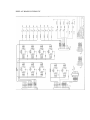
1
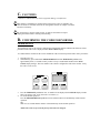
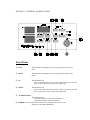
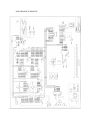
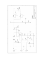
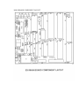
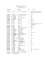
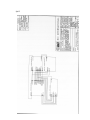
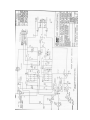
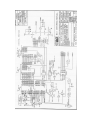
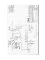
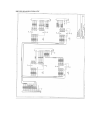
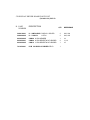
VITALMAX 530
PULSE OXIMETER
SERVICE MANUAL
CAUTION: Federal law (U.S.) restricts this
device to sale by or on the order of a physician.
510 Garden Avenue N. Clearwater, FL 33755-4126
Phone: (727) 442-8118 • Fax: (727)443-7257
Rev. 3 2/99
SECTION 1 – INTRODUCTION…………………………………….. 1
A.
B.
C.
D.
General Description ………………………………………………………………
Symbols Chart … ………………………………………………………………..
Cautions.…. ………………………………………………………………………
Confirming Code …………………………………………………………………
1-2
1-2
1-3
1-3
SECTION 2 – CONTROLS AND CONNECTORS ………………… 2
A. Front Panel ………………………………………………………………………. 2-1
B. Rear Panel ………………………………………………………………………..
2-2
SECTION 3 – DIAGRAMS ……………………………..……………. 3
A. Vitalmax 530 Block Diagram………..……………………………………………
B. Vitalmax 530 Block Diagram Description .………………………………………
C. Vitalmax 530 Hardwire Diagram..………………………………………………..
3-1
3-2
3-4
SECTION 4 – MAIN BOARD (701-060-521)………………………… 4
A.
B.
C.
D.
Schematic – Main Board…. ……………………………………………………...
Schematic – Power Section…………… .…………………………………………
Main Board Component Layout .…………………………………………………
Main Board Parts List .……………………………………………………………
4-1
4-2
4-3
4-4
SECTION 5 – SP02 BOARD (703-002-003).…………………………. 5
A. Schematic – BCI Sp02 Board (703-002-003)..……………………………………
B. BCI Sp02 Board Component Layout .……………………………………….……
C. BCI Sp02 Board Parts List .………………………………………………….……
5-1
5-6
5-8
SECTION 6 – 530 DISPLAY and DRIVER BOARD.………………. 6
A.
B.
C.
D.
E.
F.
530 Display Board Schematic (701-058-521).……………………………………
530 Display Board Component Layout.…………………..………………………
530 Display Board Parts List…………………………………………….……….
530 Display Driver Board Schematic (701-059-521)…………………………….
530 Display Driver Board Component Layout…………..……………………….
530 Display Driver Board Parts List…………………………………….………..
6-1
6-2
6-3
6-4
6-5
6-6
SECTION 1 - INTRODUCTION
FOREWARD
This Service Manual has been prepared as a guide for the repair of the VITALMAX 530
monitors by trained and technically qualified technicians only. It contains performance
specifications and information for the routine operation and maintenance of the
equipment.
NOTE
Unauthorized servicing may void the remainder of the warranty. Check with the factory
or with a local authorized Pace Tech representative to determine the warranty status of
the equipment.
Further questions regarding technical and service information should be directed to the Customer Service
Department at:
PACE TECH, INC.
510 Garden Avenue North,
Clearwater, Florida 33755-4126 USA
E.
Phone: (800) 722-3024 . (727) 442-8118
Fax: (727) 443-7257
Email: pacetech-med.com
A. GENERAL DESCRIPTION
The Vitalmax 530 monitor combines all the features of a pulse oximetry patient
monitor in one compact unit.
The Vitalmax 530 monitor is intended for use by persons trained in professional health care to measure
and monitor the following parameters:
• Blood oxygen saturation (SpO2 or Pulse oximetry)
• Pulse (SpO2) signal strength
• Pulse rate (SpO2)
Additional options offered are:
• Add-on 27 column thermal printer
B. SYMBOLS CHART
The following symbols are used on the monitors to mark equipment functions and/or features.
Symbol Description
Symbol
Description
C. CAUTIONS
- Indicate a condition that may lead to equipment damage or malfunction.
The monitor is intended to be operated from a main power source of nominally 110120V/50-60 Hz or 220-240V/50-60 Hz AC through the external AC adapter or from the
internal 6 Volt battery.
Do not autoclave, ethylene oxide sterilize, or immerse the monitor in liquid.
Unplug the monitor before cleaning or disinfecting.
D. CONFIRMING THE CODE FOR NORMAL
OPERATION
The installation code for the software configuration of the digital monitors indicates the functions of that
particular model. This code is displayed in the NEXT CYCLE display.
To confirm that the monitor has the correct installation codes for normal operation follow these procedures:
1.
2.
Turn the power on.
Simultaneously press and hold the MEMORY RECALL and the TIME/DATE pushbutton for
approximately three (3) seconds or until you hear a “beep” sound and the number in the NEXT
CYCLE display changes. This new number is the software configuration code of the monitor. Verify
the code is set at two (2).
3.
Press the TIME/DATE pushbutton once. A number will be displayed in the PULSE display window.
This is the printer code. Verify the code is set at three (3).
To resume normal operation:
Press the MEMORY RECALL pushbutton twice and the monitor will immediately resume normal
operation.
OR
Wait ten (10) seconds and the monitor will automatically resume normal operation.
4.
NOTE: The codes are preset at the factory and cannot be changed.
SECTION 2 – CONTROLS and INDICATORS
Front Panel
1. LOW
This pushbutton will display the previously programmed lower alarm
limits.
2. HIGH
This pushbutton will display the previously programmed upper alarm
limits.
3. UP
This pushbutton will:
- increase the alarm limits, print cycle time, alarm reset interval, time and
date, or initiate the memory recall in ascending order.
4. DOWN
This pushbutton will:
- decrease the alarm limits, print cycle time, alarm reset interval, time and
date, or initiate the memory recall in descending order.
5. ALARM SILENCE
This pushbutton will:
- silence the alarms for a selected period of time, or
- program the automatic alarm reset interval.
6. MEMORY This pushbutton will recall previous readings in the memory while
monitoring in the Auto or Stat modes.
7. AUTO PRINT
This pushbutton places the monitor in Auto Print mode of operation.
Repeated readings will be printed at desired set intervals of time.
8. HOLD
This pushbutton places the monitor on HOLD and aborts the Auto Print
mode. The PRINT CYCLE and NEXT PRINT LED displays will blink as
long as the monitor is on Hold.
9. TIME / DATE
This pushbutton allows viewing and setting of the time and date.
10. SpO2 RECEPTACLE
This receptacle accepts the pulse oximetry extension cable plug.
Rear Panel
1.
SOUND
This control knob adjusts the volume of the pulse sounds: turning the knob
clockwise will increase the volume: turning the knob counterclockwise
will decrease the volume. This knob does not adjust the audio alarm.
2.
PRINTER This receptacle provides parallel signal lines to the optional add-on 27
column thermal printer.
3.
FUSE HOLDERS
The monitor is equipped with two fuses designated F1 and F2, each protecting a
different power input:
F1 – This fuse protects the internal battery. If it is blown, the
monitor can continue to operate on the AC power supply.
Battery operation is not possible until the fuse is replaced.
F2 – This fuse protects the AC power supply line. If it is blown,
the monitor can continue to operate under battery power.
However, the internal battery cannot be recharged until this
fuse is replaced.
4.
AC ADAPTER
This receptacle accepts the AC adapter used for continous AC operation or
to charge the internal battery.
5.
BATTERY DISPOSAL SYMBOL
“Contains lead-acid battery; please dispose properly in recycle container. Do
not incinerate or throw in the trash.”
6.
POWER
” to “off, .”
This toggle switch turns the power from “on,
The monitor will continue to charge the battery as long as the power
supply is plugged in, even if the power switch is in the “off” position.
MAIN BOARD SCHEMATIC
SCHEMATIC – POWER SECTION
MAIN BOARD COMPONENT LAYOUT
MAIN BOARD PARTS LIST
701-060-521 (530) REV. F
PART NUMBER
101-118-004
DESCRIPTION
CAP 0.1uF
50V
QTY.
20% 0.2 LS MONOLITHIC DIP
15
F.
DESIGNATION
DC1,DC3, DC4, DC6, DC8, DC9, DC10,
DC13, DC14, DC15, DC16, DC18, DC39,
C31
101-136-002
CAP 47uF
16V
20% RADIAL ELECTROLYTIC
2
101-148-002
CAP 2200uF 16V
20% RADIAL ELECTROLYTIC
1
C10, C20
C30
102-000-000
RES 0 OHM
.25W 5% CF
1
R96
102-103-005
RES 2.7 OHMS
5W
1
R102
102-121-001
RES 15 OHMS
.25W 5% CF
1
R100
102-130-001
RES 75 OHMS
.25W 5% CF
1
R91
102-156-001
RES 1K
.25W 5% CF
2
R103, R106
5% SILICONE WW
102-159-001
RES 1.5K
.25W 5% CF
1
R107
102-170-001
RES 4.7K
.25W 5% CF
2
R87, R101
102-171-001
RES 5.1K
.25W 5% CF
1
R86
102-183-002
RES 10K
.25W 5% MF
11
102-191-001
RES 22K
.25W 5% CF
3
R83, R88, R89, R90, R95, R97, R98, R99,
R105, R108, R110
R84, R85, R109
102-203-001
RES 51K
.25W 5% CF
1
R92
102-213-001
RES 110K
.25W 5% CF
1
R93
103-104-002
POT 50K
10 TURN UP POTENTIOMETER
2
R94, R104
104-101-001
TRA MPSA13
NPN TRANSISTOR
1
Q2
104-103-001
TRA 2N3904
NPN TRANSISTOR
1
Q1
105-104-001
CRY 11.0592 Mhz
OSCILLATOR
1
U2
107-101-001
DIO 1N4148
SIGNAL DIODE
1
D5
107-103-001
DIO 1N4004
RECTIFIER DIODE
4
D1, D2, D3, D4
107-104-001
DIO
ADJUSTABLE ZENER DIODE
1
D6
201-101-001
REL TAKAMISAWA
SPDT RELAY
1
K1
204-102-001
REG LM2940CT
5V REGULATOR
2
VR1, VR2
302-003-001
IC 27C512-15
EPROM
1
U7
302-012-001
IC 62256A
STATIC RAM
1
U8
303-006-001
IC 82C55 or D71055C PROG. INTERFACE
2
U9, U10
303-016-002
IC 80C320
MICROPROCESSOR
1
U3
305-005-001
IC ADC0844BCN
A/D CONVERTER
1
U18
305-012-001
IC 82C54 or D71054C
305-014-001
IC DS1232
305-017-001
305-058-001
LM385BYZ
LZ-5H-C
1
U13
POWER ON RESET
1
U1
IC ULN2003
7 CHANNEL INPUT DRIVER
1
U19
IC DS12887
128 BYTE TIMER
1
U16
308-017-001
IC 74LS74AN
FLIP FLOP
2
U14, U39
308-019-001
IC 74HC7001
HEX SCHMIDT TRIGGER
1
U4
U5
PROG. TIMER 8MHz
308-021-002
IC 74LS373
LATCH
1
308-025-001
IC 74HCT244
BUFFER
1
U15
308-028-002
IC 74LS138
DECODER
1
U6
402-031-002
CON 2 PIN
HEADER WITH LOCK
7
J3, J5, J5V, J7, J8, JBATT, JAC
402-033-002
CON 3 PIN
HEADER WITH LOCK
1
J6
*
CON 14 PIN
HEADER
cut from 403-021-001
1
J40
403-020-005
CON 26 PIN
HEADER
cut from 403-021-001
1
J4
701-060-001
PCB 530 MAIN BOARD REV.F
1
SpO2
71002B3-PWB ASM OEM
REV. 9 7-20-95
G. Spo2 SURFACE MOUNT COMPONENTS
DESCRIPTION
QTY
DESIGNATION(S)
MANUFACTURER’S PART NO.
CAP X7R .001uF 50V 10%
CAP X7R .1uF 50V 10%
4
35
1206 PACKAGE (ANY MFR.)
CAP COG 120pF 50v 5%
CAP COG 22pF 50v 5%
CAP TANT 10uF 16V 10%
CAP X7R .01uF 100V 10%
CAP COG 10pF 50V 10%
CAP TANT 1uF 16V 10%
2
3
6
1
3
1
C1,C2,C21,C22
C3,C7,C8,C11,C12,C14,C15,
C17,C27,C35,C37,C38,C41,
C44,C45,C46,C47,C49,C50,
C51,C54,C56,C57,C58,C61,
C63,C64,C66,C68,C72,C73,
C74,C76,C79,C500
C5, C6
C9, C18, C48
C13,C16,C19,C65,C67,C77
C501
C52, C59, C60
C62
1206 PACKAGE (ANY MFR.)
1206 PACKAGE (ANY MFR.)
6032 PACKAGE (ANY MFR.)
1206 PACKAGE (ANY MFR.)
1206 PACKAGE (ANY MFR.)
3216 PACKAGE (ANY MFR.)
DIODE DUAL 200mA 30V
DIODE DUAL HIGH SPEED SW
2
3
D3, D5
D1, D6, D7
BAT54C PHILIPS/AMPEREX
BAV99LT1 MOTOROLA
FUSE FAST-ACT 2A 125V
1
F1
7243 PACKAGE (ANY MFR.)
FITER FERRITE SUPPRESS. 80 ohm
(IMP) @ 100MHz 500mA
8
FB1, FB2, FB3, FB4, FB5, FB6, L1,
L3
BLM41A01PT (ANY MFR.)
FILTER COMMON MODE 15mH 1:1
TURN RATIO DIP PACK
1
L6
500-1579 B.H. ELEC.
INDUCTOR 10 uH 250mA 10%
1
L8
1812 PACKAGE (ANY MFR.)
TRAN PNP 500mA 60V
TRAN NPN 500mA 60V
TRAN NPN 200mA 350mW 40v
2
2
2
Q1, Q4
Q2, Q3
Q10, Q11
MMBTA55LT1 MOTOROLA
TMPTA05LT ALLEGRO
MMBT3904LT1 MOTOROLA
FET 60V 0.5A
2
Q9, Q12
2N7002LT1 MOTOROLA
2N7002LT1 NATIONAL
R1,R2
R3,R4,R7,R8,R41,R42,R51
R5, R6
R9
R10
R11
R12
R13
R14
R15, R16
R57
R22, R24
R23, R25, R26, R30, R31, R33,
R38, R45
R29, R36
R32
R34, R35, R40
R37
R39
R43, R44, R46, R47
R48
R50, R502
R52
R56
1206 PACKAGE (ANY MFR.)
1206 PACKAGE (ANY MFR.)
1206 PACKAGE (ANY MFR.)
1206 PACKAGE (ANY MFR.)
1206 PACKAGE (ANY MFR.)
1206 PACKAGE (ANY MFR.)
1206 PACKAGE (ANY MFR.)
1206 PACKAGE (ANY MFR.)
1206 PACKAGE (ANY MFR.)
1206 PACKAGE (ANY MFR.)
1206 PACKAGE (ANY MFR.)
1206 PACKAGE (ANY MFR.)
1206 PACKAGE (ANY MFR.)
RESISTOR
RESISTOR
RESISTOR
RESISTOR
RESISTOR
RESISTOR
RESISTOR
RESISTOR
RESISTOR
RESISTOR
RESISTOR
RESISTOR
RESISTOR
5% 1/8W
1% 1/8W
1% 1/8W
5% 1/8W
5% 1/8W
5% 1/8W
5% 1/8W
5% 1/8W
5% 1/8W
1% 1/8W
5% 1/8W
5% 1/8W
1% 1/8W
47 ohm
10K
45.3K
560 ohm
270 ohm
5.6K
10 ohm
5.1 ohm
2.7K
2.49K
1M
4.7K
100K
2
7
2
1
1
1
1
1
1
2
1
2
8
RESISTOR
RESISTOR
RESISTOR
RESISTOR
RESISTOR
RESISTOR
RESISTOR
RESISTOR
RESISTOR
RESISTOR
1% 1/8W
5% 1/8W
1% 1/8W
1% 1/8W
1% 1/8W
5% 1/8W
1% 1/8W
1% 1/8W
1% 1/8W
5% 1/8W
56.2K
620K
20K
162K
13.3K
47K
200 ohm
30.9K
28K
27 ohm
2
1
3
1
1
4
1
2
1
1
1206 PACKAGE (ANY MFR.)
1206 PACKAGE (ANY MFR.)
1206 PACKAGE (ANY MFR.)
1206 PACKAGE (ANY MFR.)
1206 PACKAGE (ANY MFR.)
1206 PACKAGE (ANY MFR.)
1206 PACKAGE (ANY MFR.)
1206 PACKAGE (ANY MFR.)
1206 PACKAGE (ANY MFR.)
1206 PACKAGE (ANY MFR.)
DESCRIPTION
QTY
DESIGNATION(S)
MANUFACTURER’S PART NO.
SOCKET 32 POS. PLCC
1
U22
821977-1 AMP
IC EPROM 27C256 SMD
IC DUAL OP AMP
IC AD711JR
IC QUAD 2 INPUT NAND GATE
IC SPST CMOS
IC MULTI/DEMULTIPLEXER
IC 12BIT SERIAL INPUT, DAC
1
4
2
1
1
1
1
U22
U3, U5, U12, U14
U4, U16
U6
U11
U13
U15
IC 8BIT CMOS MPU 8MHz
IC TRIGGER INVERTER
IC 8BIT ADDRESSABLE
1
1
1
U17
U19
U20
IC DECODER/DEMULTIPLEX.
IC 8Kx8 CMOS SRAM 100nS
IC 12BIT A/D CONVERTER
IC +5V ADJUSTABLE CMOS
1
1
1
1
U21
U23
U24
U25
BCI P/N 71021B1
TLC272CD TEXAS INST.
AD711JR ANALOG DEVICES
MC74HC132AD MOTOROLA
DGG308ACY HARRIS,SILICON.
MC14051BD MOTOROLA
MAX543BCWE MAXIM or
72032B1 BCI INTERNATIONAL
HD64180RF-8 HITACHI
MC74HC14AD MOTOROLA
MC74HC259D MOTOROLA or
CD74HC259M HARRIS
MC74HC139AD MOTOROLA
HM6264ALFP-15T HITACHI
AD787OJP ANALOG DEVICE
MAX638ACSA MAXIM
THRU HOLE COMPONENTS & MISCELLANEOUS
DESCRIPTION
QTY
DESIGNATION(S)
MANUFACTURER’S PART NO.
CAP LOW/IMP 470uF 10V 20%
CAP LOW/PRO 100uF 6V 20%
CAP LOW/IMP 680uF 6.3V 20%
Or 470uF 10V NOT TO EXCEED 13mm
IN HEIGHT
CAP STA/METAL .1uF 50V 5%
CAP P/FLM .0015uF 100V 10%
CAP STA/METAL .39uF 50V 5%
2
2
2
C4, C75
C20, C28
C30, C39
ECA-1AFQ471 PANASONIC
107R22025M ILLINOIS CAP.
ECAOJFQ681 PANASONIC
2
1
1
C42
C43
C53
ECQ-V1H104JZ3 PANASONIC
QYA2A152KTP NICHICON
ECQ-V1H3393JZ PANASONIC
IC 5V ECONORESET
1
U18
DS1233Z-15 DALLAS SEMI.
INDUCTOR RAD 120uH 0.5A
1
L9
BCI P/N 71049B2
CRYSTAL 6.11MHz
1
X1
FX3-6.144MHz FOX ELEC.
TEST POINT PC MOUNT
13
TP6, TP7, TP8, TP9, TP11,
TP14, TP15, TP16, TP17, TP18,
TP19, TP20, TP21
TP-103-03 COMPONENTS CO.
HEADER .100 2 POSITION
2
P1, P2
103321-2 AMP
RECEPTACLE 9 POSITION
JACK STEREO 3.5mm
SOCKET .100 8 POS. SIP
1
1
1
J1
J2
JP1
DB9-F 747905-2 AMP
16PJ108 MOUSER
744-8 T&B ANSLEY or
CES-108-01-T-S SAMTEC
22 GAUGE HOOK-UP WIRE
A/R
JUMPER
ANY (AS REQUIRED)
PWB FAB (Rev D. films)
COVER SHIELD NEWOX1
SOFTWARE ASM
BARRIER INSULATING 2 MIL
BARRIER INSULATING 11 MIL
GLUE, HOT MELT (FULLER)
1
1
1
1
1
1/R
400
401
402
404
405
406
BCI P/N71001B1(Rev. 1 Drawing)
BCI P/N71017B1
*-BCI P/N 71029A3
*-BCI P/N 20511B1
*-BCI P/N 20511B2
HM-2124-10
*- INDICATES SUPPLIED BY BCI
DISPLAY BOARD SCHEMATIC
DISPLAY BOARD COMPONENT LAYOUT
530 DISPLAY BOARD PARTS LIST
(701- 058 - 521) REV. H
PART NUMBER
DESCRIPTION
QTY.
REFERENCE
102-115-001
102-135-001
102-147-001
10 OHMS .25W 5% CF
150 OHMS .25W 5% CF
470 OHMS .25W 5% CF
1
1
1
R25
R27
R26
109-102-002
HDSP-H103 DSP LED 1 DIGIT RED E-
7
109-106-001
109-107-001
109-123-001
109-123-002
DSP LED BARGRAPH
LTA1000HR
MTN4139CSR DSP LED 1DIGIT .39”
LED DSP GREEN LED 2X5MM
LED DSP YELLOW LED 2X5MM
1
2
4
1
U4, U5, U6, U7, U8,
U9, U10
U31
U2, U3
D7, D8, D10, D11
D12
202-118-001
SPST SWITCH 12X12MM
9
202-119-007
SWI BUTTON WHITE CDS7 SERIES
9
205-103-001
RPK 10K
2
S1, S4, S5, S6, S7,
S8, S9, S10, S11
S1, S4, S5, S6, S7,
S8, S9, S10, S11
RP1, RP2
CON12 12 PIN HEADER
CON20 20PIN HEADER
Cut from 402-021-001 (40 pin header)
1
2
J3
J1, J2
PCB 530 DISPLAY BOARD REV.H
1
*
*
*
701-058-001
B3F4050
8PIN SIP BUSSED
DRIVER BOARD SCHEMATIC
DRIVER BOARD COMPONENT LAYOUT
530 DISPLAY DRIVER BOARD PARTS LIST
(701-059- 521) REV. D
H. PART
NUMBER
DESCRIPTION
QTY.
REFERENCE
308-018-001
308-024-002
IC ICM7218DIPI DISPLAY DRIVER
IC 74LS374
LATCH
2
2
U22, U24
U23, U25
403-020-005
403-022-001
403-022-005
CON26 26 PIN HEADER
CON20 20 PIN RECEPTACLE HEADER
CON12 12 PIN RECEPTACLE HEADER
1
2
1
J4
J1, J2
J3
701-059-001
PCB 530 DISPLAY DRIVER REV.D
1