1
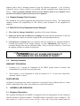
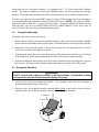
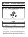
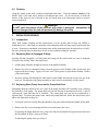
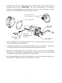
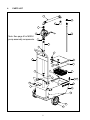
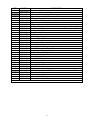
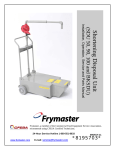
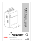
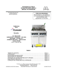
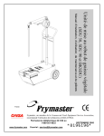
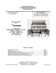
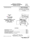
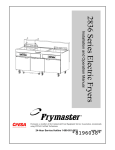
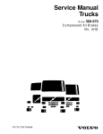
VEGETABLE OIL DISPOSAL UNIT (MSDU)
OPERATOR & SERVICE MANUAL
MANUFACTURED BY
P.O. BOX 51000
SHREVEPORT, LOUISIANA
71135-1000
PHONE 1-318-865-1711
1-800-24 FRYER
This equipment chapter is to be inserted in the Fryer
section of the Equipment Manual.
1
1.1
1.2
1.3
1.4
1.5
1.6
INTRODUCTION ............................................................................ 1
Service Information and Parts Ordering ......................................... 1
Installation, Operating and Service Personnel................................ 1
Definitions....................................................................................... 1
Shipping Damage Claim Procedure ............................................... 2
What To Do If Your Equipment Arrives Damaged .......................... 2
Warranty Statement........................................................................ 2
2.
2.1
2.2
2.3
2.4
ASSEMBLY AND OPERATION ..................................................... 2
Equipment Description ................................................................... 2
Equipment Assembly...................................................................... 3
Equipment Operation...................................................................... 3
Cleaning ......................................................................................... 5
3.
3.1
3.2
3.3
SERVICE PROCEDURES ............................................................. 5
General........................................................................................... 5
Replacing Worn or Damaged O-Rings ........................................... 5
Replacing Worn Pump Vanes and/or Pump Shaft Seal.................. 5
4.
PARTS LIST................................................................................... 8
Frymaster L.L.C., 8700 Line Avenue 71106, 5489 Campus Drive 71129
P.O. Box 51000, Shreveport, Louisiana 71135-1000
PHONE 318-865-1711
FAX 318-219-7135
PRINTED IN THE UNITED STATES
SERVICE HOTLINE 1-800-24-FRYER
www.frymaster.com
E-mail: [email protected]
MAY 2009
*8195236*
NOTICE
IF, DURING THE WARRANTY PERIOD, THE CUSTOMER USES A PART FOR THIS
ENODIS EQUIPMENT OTHER THAN AN UNMODIFIED NEW OR RECYCLED PART
PURCHASED DIRECTLY FROM FRYMASTER DEAN, OR ANY OF ITS AUTHORIZED
SERVICE CENTERS, AND/OR THE PART BEING USED IS MODIFIED FROM ITS
ORIGINAL CONFIGURATION, THIS WARRANTY WILL BE VOID.
FURTHER,
FRYMASTER DEAN AND ITS AFFILIATES WILL NOT BE LIABLE FOR ANY CLAIMS,
DAMAGES OR EXPENSES INCURRED BY THE CUSTOMER WHICH ARISE
DIRECTLY OR INDIRECTLY, IN WHOLE OR IN PART, DUE TO THE INSTALLATION
OF ANY MODIFIED PART AND/OR PART RECEIVED FROM AN UNAUTHORIZED
SERVICE CENTER.
NOTICE
Drawings and photos used in this manual are intended to illustrate operational,
cleaning and technical procedures and may not conform to on-site management
operational procedures.
WARNING
Improper installation, adjustment, alteration, service or maintenance can cause
property damage, injury or death. Read the installation, operating and maintenance
instructions thoroughly before installing, operating or servicing this equipment.
DANGER
Hot vegetable oil will cause severe burns. Allow vegetable oil to cool to 100°F
(38°C) before transporting to the disposal site. Use extreme caution when
transporting and disposing of spent vegetable oil.
DANGER
Before each use inspect the cover to ensure the cover gasket is present and
properly placed. DO NOT use the disposal unit if this gasket is damaged or
missing.
ii
VEGETABLE OIL DISPOSAL UNIT (MSDU)
INSTALLATION, OPERATION, SERVICE, AND PARTS
1.
INTRODUCTION
1.1 Service Information and Parts Ordering
Included with the unit when shipped from the factory is a list of Factory Authorized Service Centers
(FASCs). Refer to this list to find the FASC nearest you. If you do not have access to this list,
contact the Frymaster Technical Service Department at 1-800-24-FRYER (1-800-243-7237) or
1-318-865-1711.
Service information may be obtained by contacting your local FASC. Information may also be
obtained by calling the Frymaster Technical Service Department at 1-800-24-FRYER (1-800-2437237) or 1-318-865-1711 or e-mail: [email protected]. In order to assist you as quickly as
possible, the FASC or Service Department representative requires certain information about your
equipment. The information is printed on a data plate located on the tank cover. When requesting
service, please have the following information ready:
Model Number:
Serial Number:
In addition to the model number, and serial number, please be prepared to describe the nature of the
problem and have ready any other information that you think may be helpful in solving your
problem. Parts orders may be placed directly with your local FASC or distributor. When ordering
parts, the following information is required:
Model Number:
Serial Number:
Item Part Number:
Quantity Needed:
RETAIN AND STORE THESE INSTRUCTIONS IN A SAFE PLACE FOR FUTURE USE.
1.2 Installation, Operating and Service Personnel
Installation, Operating, and Service information for this equipment has been prepared for use by
qualified and/or authorized personnel only, as defined in Section 1.3.
1.3 Definitions
QUALIFIED AND/OR AUTHORIZED OPERATING PERSONNEL
Qualified/authorized operating personnel are those who have carefully read the information in this
manual and have familiarized themselves with the equipment functions, or who have had previous
experience with the operation of the equipment covered in this manual.
QUALIFIED SERVICE PERSONNEL
Qualified service personnel are those who are familiar with this equipment and who have been
authorized by Frymaster L.L.C. to perform service on equipment manufactured by Frymaster. All
authorized service personnel are required to be equipped with a complete set of service and parts
1
manuals, and to stock a minimum amount of parts for Frymaster equipment. A list of Factory
Authorized Service Centers (FASCs) was included with this equipment when shipped from the
factory. Unless specifically indicated otherwise in this manual, failure to use qualified service
personnel will void the Frymaster Warranty on this equipment.
1.4 Shipping Damage Claim Procedure
This equipment was carefully inspected and packed before leaving the factory. The transportation
company assumes full responsibility for safe delivery upon acceptance of the equipment for
transport.
1.5 What To Do If Your Equipment Arrives Damaged
1. File a claim for damages immediately, regardless of the extent of damages.
2. Inspect for and record all visible loss or damage and ensure that this information is noted on
the freight bill or express receipt and is signed by the person making the delivery.
3. Concealed loss or damage that was unnoticed until the equipment was unpacked should be
recorded and reported to the freight company or carrier immediately upon discovery. A
concealed damage claim must be submitted within 15 days of the date of delivery. Ensure that
the shipping container is retained for inspection.
DOES NOT ASSUME RESPONSIBILITY
FOR DAMAGE OR LOSS INCURRED IN TRANSIT.
1.6
Warranty Statement
WARRANTY PROVISIONS
1.
Frymaster L.L.C. warrants all components of the MSDU against defects in material and
workmanship for a period of one year (parts only).
2.
This warranty is void if equipment is found by Frymaster L.L.C. to have been subjected to
alteration, misuse, or abuse.
PARTS RETURN
All defective in-warranty parts must be returned to a Frymaster Factory Authorized Service Center
(FASC) within 60 days for credit. After 60 days, no credit will be allowed
2.
ASSEMBLY AND OPERATION
2.1 Equipment Description
The Vegetable Oil Disposal Unit (MSDU) is designed for the safe transportation of used cooking oil
from the kitchen to a disposal container. The MSDU holds to 50 pounds/23 kg of cooking oil. The
unit consists of a tank to receive waste oil from a fryer and a heavy-duty manual pump for
2
transferring the oil to a disposal container. It is equipped with 7" (178 mm) wheels and a foldable
handle. The pump is mounted at a convenient height that allows it to be operated from a standing
position. The height of the discharge pipe allows pumping directly into a standard 55-gallon drum.
With the cover open, the top of the MSDU tank is 9¾ inches (248 mm) above the floor, permitting it
to be positioned directly beneath the drains of McDonald’s fryers. (NOTE: The tanks on MSDUs
built before January 2004 are 11½ inches (292 mm) high.). If using an MSDU built before January
2004 the filter pan cover on BIPH14/MPH14 Series or BIPH52/MPH52 Series fryers must be
removed to allow the unit to be positioned beneath the drain.
2.2
Equipment Assembly
Assembly of the unit is a four-step process:
1. Remove the two bolts (or lock pins if manufactured prior to May 2006) from the handle-mounting
bracket and raise the handle to the upright position. Reinstall the bolts (or lock pins) in the bracket.
2. Ensure the O-rings and the bottom 2 inches of the suction tube are lubricated with Accrolube
with Teflon or an equivalent light oil or grease.
3. Turn the pump and suction tube upside down and carefully pour no more than one cup of cooking
oil down the tube. Rotate the pump handle slowly three or four times to prime the pump.
4. Insert the suction tube through the pipe bracket on the handle and into the pickup tube on top of
the reservoir. Push down on the pump assembly and ensure the suction tube is fully seated.
2.3 Equipment Operation
WARNING
DO NOT use this unit to dispose of water or Boil-out solution. Introduction of water
or solvents into the unit will permanently damage the pump.
1. Turn the fryer off prior to draining into MSDU. If so equipped, ensure the fryer drainpipe is
firmly threaded into the frypot drain valve.
2. Open the cover, verify that the crumb screen and rubber gasket on the inside cover are in place,
and position the unit so that the opening is directly under the frypot drainpipe.
Cover Gasket
Crumb Tray
3
DANGER
Before each use inspect the cover to ensure the cover gasket is present and
properly placed. DO NOT use the disposal unit if this gasket is damaged or
missing.
3. Slowly open the drain valve. Regulate flow with the drain valve to prevent splashing.
DANGER
DO NOT OVERFILL! Do not fill the reservoir above the fill lines on the sides of the
reservoir. Moving the MSDU with an overfilled reservoir may result in spills and
injury to personnel who come in contact with the spilled oil.
4. Carefully withdraw the unit far enough to allow the cover to be closed. Latch the cover in the
closed postion. Using the handle, carefully tip the unit back slightly for ease of handling and roll
the unit to the disposal site.
WARNING
DO NOT use the pump or discharge piping assembly as a handle!
DANGER
To minimize the potential for burns, oil must always be allowed to cool below 100°F
(38°C) before draining into the MSDU and transporting to the disposal area.
However, DO NOT allow oil to congeal in the MSDU.
The unit is designed to be moved, when properly filled, at an average walking pace on a flat
surface. Care must be taken at all times when moving hot oil. Rough terrain or sudden stops
and starts may cause the contents of the reservoir to spill or splash out of the reservoir,
possibly causing serious injury to personnel. Always ensure that the cover is latched shut
when moving the unit.
5. At the disposal site, lift the pump assembly lock pin and rotate the discharge pipe as necessary to
position the discharge nipple over the opening of the disposal container. Release the lock pin to
secure the pump assembly in position. Turn the pump handle clockwise. The pump should start
discharging oil after a few turns. Continue turning the handle until the MSDU reservoir is empty.
NOTE: The pump is NOT self-priming. If it has not been used for several days, it may have lost
its prime and may need to be re-primed in accordance with Step 3 of Section 2.2.
4
2.4 Cleaning
Clean the crumb screen with a solution of detergent and water. Clean the exterior surfaces of the
MSDU with a soft cloth and a solution of detergent and water. It is not necessary to clean the
interior of the reservoir, but if desired it may be wiped down with clean paper towels to remove
excess residual oil.
WARNING
DO NOT clean the interior of the reservoir with water or detergent. Introduction of
water or detergent into the unit will permanently damage the pump.
3.
SERVICE PROCEDURES
3.1 Introduction
Other than routine cleaning and the replacement of worn suction tube O-rings, the MSDU is
maintenance free. After long use, the pump vanes and pump shaft seal may require replacement due
to wear. Frymaster recommends worn pump vanes and/or pump shaft seals be replaced by an FASC,
but store personnel may perform these service actions without voiding the warranty.
3.2 Replacing Worn or Damaged O-Rings
If pump efficiency degrades, it is likely that the O-rings on the suction tube are worn or damaged.
To replace the O-rings, follow the steps below.
1. Lift the pump assembly straight up and out of the handle assembly.
2. Remove the worn or damaged O-rings from the grooves at the bottom of the suction tube and
replace with new O-rings. Apply Accrolube with Teflon grease or equivalent to bottom 2 inches
of the suction tube.
3. Insert the suction tube through the tube bracket in the handle and into the receiver on top of the
reservoir. Push down on the pump assembly to make sure the suction tube is fully seated.
3.3 Replacing Worn Pump Vanes and/or Pump Shaft Seal
Depending upon the amount of use, the vanes in the pump assembly will eventually wear, reducing
the efficiency of the pump. The pump shaft seal can also become worn and start to leak. A kit for
replacing the vanes and the seal is available. The pump shaft seal can also be purchased as a
separate item. To replace the pump vanes, and/or the pump shaft seal, follow the steps below (refer
also to the illustration on Page 6).
1. Loosen the setscrew securing the pump handle to the pump shaft and slip the handle off the shaft.
2. Remove the five screws securing the front cover and remove the cover.
If replacing the pump shaft seal only, remove the old seal and install the replacement as shown in
the illustration on Page 6, then go to Step 5.
If replacing the pump vanes, go to Step 3.
5
3. Grasp the pump shaft and carefully pull the rotor assembly straight out of the pump housing far
enough to expose the vanes. IMPORTANT: The vanes are spring-loaded. Use one hand to
hold the vanes while pulling the rotor assembly the rest of the way out of the housing. Carefully
release the vanes and discard the worn vanes, springs, and rods.
Pump shaft seal fits into the
recess of the pump cover.
Step 5 - Replace gasket.
Step 1 - Loosen
setscrew and
remove handle.
Step 4 - Replace
vanes, spring,
and rod.
Step 3 - Grasp
shaft and pull
rotor assembly
out of housing.
Step 2 - Remove cover
screws and cover.
4. Use fine sandpaper to clear the pump housing of rust or corrosion, which can wear the veins.
Clean the pump housing of sanding debris.
5.
Assemble the replacement vanes, spring and rod and place in the rotor assembly. Compress the
vane spring and carefully insert the rotor assembly back into the pump housing.
6. Position the replacement gasket on the pump body, slip the cover over the shaft, and align the
pins in the cover with the holes in the pump housing. Reinstall the five screws removed in Step
2 and tighten securely (torque to approximately 60 inch-pounds).
7. Slip the pump handle back onto the shaft and align the screw hole in the handle with the screw
hole in the shaft. Tighten the setscrew loosened in Step 1 securely.
6
THIS PAGE INTENTIONALLY LEFT BLANK.
7
4.
PARTS LIST
1
3
2
5
6
Note: See page 6 for MSDU
pump assembly components.
4
7
8
9
11
10
12
13
14
17
16
15
20
21
22
24
25
19
26
27
18
28
8
23
ITEM
1
PART #
823-4600
823-4598
2
813-0115
3
813-0031
4
810-1845
5
813-0109
6
810-0784
*
826-1053
*
816-0401
7
813-0032
8
823-4581
9
810-0777
10
823-2038
11
809-0119
12
823-1683SP
13
816-0134
14
816-0133
15
824-0438
16
826-1376
17
816-0132
18
809-0200
19
809-0193
20
809-0191
21
809-0047
22
810-0742
23
809-0359
24
809-1001
25
802-0227
26
823-4580SP
826-2103
27
810-0783
28
810-1112
*
815-0661
*
815-0565
* Not Illustrated
COMPONENT
Pipe Assembly, Discharge
Standard (includes Item 2)
For use with Item 4 (Hose Discharge) (includes Item 3)
Nipple, ¾-inch x 3-inch Toe
Bushing, ¾-inch x ½-inch
Hose, 24-inch Discharge (Optional) (use 810-2797 for 48-inch hose)
Nipple, ¾-inch x Close
Pump (includes handle 810-0657, which may be ordered separately)
Kit, Pump Repair (includes two vanes, one spring, one rod, one gasket.)
Seal, Pump Shaft
Bushing, 1-inch X ¾-inch Hex
Pipe Assembly, Suction
Pin, Plunger
Handle Assembly
Screw, 10-32 x ½" Slotted Head
Cover and Hinge Assembly (does not include gasket (item 13))
Gasket, Cover (attach with 3M 1300L adhesive or equivalent)
Gasket, Cover Hinge
Screen, Crumb
Nut, 10-32 Keps Hex (Pkg. of 10)
O-ring, Suction Pipe Assembly (2 required)
Washer, Wheel ½” SAE
Washer, ¼-inch Nylon Flat
Lock Washer, ¼-inch
Nut, ¼-20 S/S Cap
Latch, Tank Cover
Screw, #8 x ¼-inch
Screw, ¼-20 x ½” Slotted Head
Label, Fill Line
Tank and Axle Assembly
MSDU50 Retrofit Kit for MSDU’s manufactured prior to Jan. 2004
Cotter Pin, Wheel
Wheel, 7-inch x 1½-inch
Adhesive, 3M 1300L
Grease, Accrolube w/ Teflon
9
Frymaster, L.L.C., 8700 Line Avenue, PO Box 51000, Shreveport, Louisiana 71135-1000
Shipping Address: 8700 Line Avenue, Shreveport, Louisiana 71106
TEL 1-318-865-1711
FAX (Parts) 1-318-688-2200
PRINTED IN THE UNITED STATES
FAX (Tech Support) 1-318-219-7135
SERVICE HOTLINE
1-800-551-8633
819-5236
MAY 2009