1
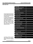
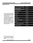
2001 FORESTER SERVICE MANUAL
QUICK REFERENCE INDEX
BODY SECTION
This service manual has been prepared
to provide SUBARU service personnel
with the necessary information and data
for the correct maintenance and repair of
SUBARU vehicles.
This manual includes the procedures for
maintenance, disassembling, reassembling, inspection and adjustment of components and diagnostics for guidance of
experienced mechanics.
Please peruse and utilize this manual
fully to ensure complete repair work for
satisfying our customers by keeping their
vehicle in optimum condition. When
replacement of parts during repair work is
needed, be sure to use SUBARU genuine parts.
All information, illustration and specifications contained in this manual are based
on the latest product information available at the time of publication approval.
FUJI HEAVY INDUSTRIES LTD.
G8050GE6
SEATS
SE
1.
2.
3.
Page
General Description.....................................................................................2
Front Seat....................................................................................................5
Rear Seat ....................................................................................................6
GENERAL DESCRIPTION
Seats
1. General Description
A: COMPONENT
1. FRONT SEAT
S908001
S908001A05
S908001A0501
S5M0440A
(1)
(2)
(3)
(4)
(5)
(6)
(7)
Lumbar lever
Lumbar cover
Lumbar unit
Headrest
Backrest
Cushion
Cushion frame
(8)
(9)
(10)
(11)
(12)
(13)
(14)
Lifter dial
Hinge cover OUT
Reclining lever
Hinge ASSY
Hinge spring cover
Slide rail ASSY IN
Connecting wire
SE-2
(15) Slide rail ASSY OUT
(16) Bracket
Tightening torque: N·m (kgf-m, ft-lb)
T1: 18 (1.8, 13)
T2: 52 (5.3, 38)
GENERAL DESCRIPTION
2. REAR SEAT
Seats
S908001A0505
S5M0508A
(1)
(2)
(3)
(4)
(5)
(6)
Backrest RH
Backrest LH
Headrest OUTSIDE
Headrest CENTER
Hinge RH
Hinge CENTER
(7)
(8)
(9)
(10)
(11)
Hinge LH
Cushion
Striker
Cap
Webbing guide
SE-3
Tightening torque: N·m (kgf-m, ft-lb)
T1: 10 (1.0, 7.2)
T2: 25 (2.5, 18.1)
GENERAL DESCRIPTION
Seats
B: CAUTION
S908001A03
쐌 Take care not to contaminate or damage seat
surface.
쐌 While loading to or unloading to vehicle, take
care not to contact body.
쐌 When removing front seat from a side airbag
loaded vehicle, follow cautions given in the airbag
section.
SE-4
FRONT SEAT
2. Front Seat
A: REMOVAL
S908343
S908343A18
1) While operating button (located on top of
backrest), lift headrest out with hand placed
between backrest and headrest.
Seats
CAUTION:
쐌 When removing seat from vehicle, take care
not to damage body, seat, or trim.
쐌 After the front seat has been removed from
side airbag equipped vehicle, store it as
instructed in AIRBAG REPAIR SECTION. <Ref.
to AB-15, CAUTION, Side Airbag Module.>
B: INSTALLATION
S908343A11
1) While operating button (located on top of
backrest), lift headrest out by placing your hand
between backrest and headrest.
S5M0303
2) Pull reclining lever back to fold backrest all the
way forward. While pulling slide adjuster lever,
move seat all the way forward.
3) Remove bolt cover at rear end of slide rail.
4) Remove bolts securing seat rear.
S5M0303
2) Pull reclining lever back to fold backrest all the
way forward. Pull slide adjuster lever and move
lower slide rail all the way backward.
3) Position seat in compartment and align the
holes on the seat with the holes on the vehicle
body side.
4) Secure the front of seat using inward and outward bolts (A) and (B) in that order.
5) While pulling slide adjuster lever, move seat all
the way forward.
6) Secure the rear of seat using inward and outward bolts (C) and (D).
S5M0366
5) While pulling slide adjuster lever, slide seat all
the way back.
6) Remove bolts securing front of seat.
S5M0227A
G5M0344
7) While disconnecting side airbag connector,
detach front seat. (Side airbag equipped vehicle)
and inner belt connector.
7) Connect inner belt connector.
8) Connect side airbag connector. (Side airbag
equipped model)
9) Install bolt cover on rear end of slide rail.
10) Install headrest on backrest.
CAUTION:
Confirm that seat can move smoothly and be
locked securely at any position.
SE-5
REAR SEAT
Seats
3. Rear Seat
A: REMOVAL
S908350
S908350A18
1) Remove bolts securing hinges (located at front
of cushion) to body.
2) Slightly raise front of cushion while pushing
down on cushion in the direction of “A”. With cushion held in that position, move it forward until it is
unhooked.
S5M0228A
3) Remove rear quarter lower trim. <Ref. to EI-39,
REMOVAL, Rear Quarter Trim.>
4) Remove bolts and nuts.
S5M0407
5) Detach backrest.
B: INSTALLATION
S908350A11
Install in the reverse order of removal.
SE-6