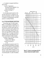
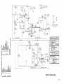
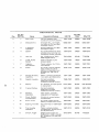
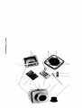
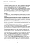
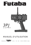
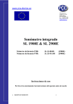
1
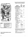
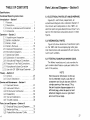
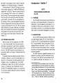
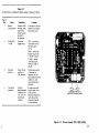
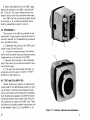
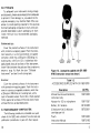
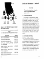
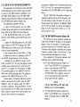
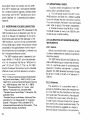
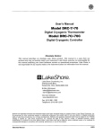
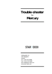
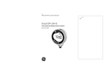
♦ PRECISION INSTRUMENTS FOR TEST AND MEASUREMENT ♦
1987 SERIES
Minical Sound-Level Calibrator
User and Service Manual
Copyright © 2014 IET Labs, Inc.
1987 im/March, 2014
IET LABS, INC.
Formerly manufactured by
GenRad
Long Island, New York - Email: [email protected]
TEL: (516) 334-5959 • (800) 899-8438 • FAX: (516) 334-5988
www.ietlabs.com
IET LABS, INC.
Formerly manufactured by
GenRad
Long Island, New York - Email: [email protected]
TEL: (516) 334-5959 • (800) 899-8438 • FAX: (516) 334-5988
www.ietlabs.com
Specifications
Appendix
Output Sound-Pressure Levels: 114 dB or 94 dB
re 20 JLPa t under reference conditions.
USE OF THE NOMOGRAPH
Output Frequency: 1000Hz ±3%.
Reference Conditions: TEMPERATURE: 20°C
(68°F). ATMOSPHERIC PRESSURE: 1013 mbart
(760 mm of Hg) (30 in. of Hg). RELATIVE
HUMIDITY: 65%. MICROPHONE EFFECTIVE
VOLUME: 0.5 cm 3 (.03 in}) (nominal for GR
1961 Electret-Condenser Microphone*).
Accuracy of Sound-Pressure Level: Under stated
reference environment conditions, ±0.25 dB for
cavity alone, or cavity when used with any adaptor
(except 1-1/8-in, adaptor: ±0.5 d8).
Temperature Coefficient of Sound-Pressure Level:
Less than ±0.02 d8/°C.
Power: Powered by 9-V alkaline battery; Mallory
MN 1604 or Eveready 522 recommended. Battery
provides at least 20 h continuous operation.
Environment: TEMPERATURE: -10 to +50°C
(+14 to +122° F), operating; -40 to+ 70°C (-40
to +140° F), storage with battery removed.
HUMIDITY: 0 to 90% RH, operating.
Mechanical: DIMENSIONS (wxhxd): Approximately 63x63x89 mm (2-1 /2x2-1 /2x3-1 /2 in.).
WEIGHT: Approximately 270 gm (9.5 oz).
ii
CORRECTION OF BAROMETRIC PRESSURE TO
STATIONAL TITUDE.
To obtain a corrected barometric pressure for a
station:
a. Determine the station's altitude above sea level.
b. Obtain a barometric pressure reading corrected
to sea level from a barometer. (If the barometer reads
only values in millimeters, find the corresponding
value of millibars from the right-hand scales.
c. Place a straight-€dge across the proper points on
the center and left-hand scales of the nomograph, and
read the actual pressure at the station, on the righthand scales.
CONVERSION FROM MILLIMETERS OF MERCURY TO INCHES OF MERCURY.
To convert from millimeters of mercury to inches
of mercury proceed as follows:
a. Find the barometric pressures value in millimeters of mercury on the right-hand scales.
b. Obtain the corresponding value in millibars from
the same scales.
c. Move to the left-hand scales and find the millibar value obtained in step b.
d. Read the corresponding value of barometric
pressure in inches of mercury from the left-hand
scales.
41
Battery Test: Internal circuitry checks condition of
battery continuously. Calibrator will not operate at
all if battery voltage falls below acceptable range.
Microphone Coupling: Transducer cavity accommodates following 1-in. microphones: GR 1961
electret-condenser,* G R 1971 ceramic, Western
Electric 640AA and Tokyo Riko MR103.
Accessories Supplied: Coupler-adaptor to accommodate G R 1962 1/2-in electret-condenser microphone* and GR 1983 Sound-Level Meter micro·
phone; carrying pouch; 3 spare desiccant kits;
battery; instruction manual.
Accessories Available: Adaptor set that includes
coupler-adaptor for 3/S.in. GR 1954 Noise
Dosimeter microphone, coupler-adaptors and "0"
ring for 1·in., 1/2-in. and 1/4-in. 8 & K microphones,
and coupler-adaptor for 1-1 /8·in. Shure Brothers
microphone.
tIn the international system of units (SI), the unit
of pressure is the pascal (Pal; 1 Pa = 1 N/m 2
= 10 dynes/cm 2 = 1
mbar.
Ref: "The International System of Units (SI),"
U.S. Dept. of Commerce, National Bureau of
Standards, NBS Special Publication 330.
S.D. Cat. No. C 13. 10:330/2, U.S. GPO,
Wash., D.C., 20402.
*U.S. Patent 4,070.741.
o·z
iii
Condensed Operating Instructions
TO ACTIVATE THE INSTRUMENT
a. Set power switch to desired calibration level
(94 dB or 114 dB l.
b. Listen for 1-kHz audible tone. If no tone is
present, replace battery (see para 2.4).
TO CALIBRATE A SOUND-MEASURING
INSTRUMENT
a. Observe 1987 desiccant through window. If
pale blue, satisfactory; if pink, replace desiccants
(see para 2.5!.
b. If microphone adaptor is required, insert it
in 1987 cavity to fit microphone under test (see
para 2.6).
c. Set instrument under test to 100 dB (if
1987 is set at 94 dB) or 120 dB (if 1987 is set at
114 dB). Instrument may be set to FAST or SLOW
response and C or A weighting.
d. Place 1987 on microphone of instrument
under test, read level and adjust its sensitivity, A
pressure-to-free-field correction (see para 2.1 0)
must be added to this reading for some microphones (refer to following table); this correction
(in dB) is to be added to the reading of the instrument under test before comparing it with the
calibrated output of the 1987 (either 94 dB or
114 dB).
Handbook of Noise Measurement
This book, by Dr. A.P.G. Peterson and
Ervin E. Gross, Jr., of the GenRad Engineering Staff covers thoroughly the subject of
noise and vibration measurement. Copies are
available from GenRad at $9.00 each, postpaid in the United States and Canada.
GR P/N 5301-8111
iv
PRESSURE-TO-FREE-FIELD CORRECTIONS*
Microphone
Manufacturer and Type
GR
Adaptor
Used
Correction
(dBI
FIat-Response-to-Random1ncidence Microphones:
GR 1961-9610 or-9601 none
( 1-in. electretl
G R 1962-9610 or -9601 1987-7061
( 1/2-in. electret)
GR 1971 (1-in. ceramic) none
1987-7061
GR 1983 Sound-Level
Meter ( 1/2-in. ceramic)
1987-7076
GR 1954 Noise
and
Dosimeter (3/8-in.
1987-7095
ceramicl
Flat-Response-toPerpendicu lar-1 ncidence
Microphones:
G R 1961-9611 or -9602 none
( 1-in. electret)
G R 1962-9611 or -9602 1987-7061
( 1/2-in. electret)
0-Ring
B& K 4131 (1-in.
( 5855-6920)
condenser It
1987-2050
B&K4133(1/2-in.
condenser)
1987-2060
B&K4135(1/4-in.
condenser)
0.0
0.0
0.0
0.1
0.0
-----
• DENOTES:
END Or CAPAC !TORS., ARM or
POTENTIOMETERS,ROTOR OF TBIMM[R
CAPACITORS,CATHODE END OF
DIOOES,PIN NO. I OF IC'S,
PIN NO.I OF RELAYS,PiN NO.I OF
CONNECTORS,COLLECTOR OF
TRANSISTORS
+
Figure 5-1. Etched-board assembly (viewed from
component side I.
38
0.3
0.1
0.2
0.0
0.0
*Measurement Conditions: Atmospheric Pressure,
760 mm (30 in.) of Hg (see para 2.9 for other
pressures).
t Additional correction required due to microphone
effective volume (refer to para 2.11 ).
v
TABLE OF CONTENTS
Parts Lists and Diagrams - Section 5
Specifications
Condensed Operating Instructions
5.1 ELECTRICALPARTSLIST AND DIAGRAMS.
Introduction- Section 1
1. 1 Purpose . . . . . . . . . . . . . . . . . .
1.2 Description . . . . . . . . . . . . . . .
1.3 Controls, Indicators and Connectors
1.4 Accessories . . . . . . . . . . . . . . .
1
1
2
2
Operation - Section 2
2.1 Unpacking and Inspection
2.2 Battery Installation
2.3 Battery Check . . . . . .
2.4 Battery Removal . . . . .
2.5 Desiccant Replacement .
2.6 Microphone Adaptors . .
2.7 Operational Check. . . .
2.8 Calibration of Instruments
2.9 Altitude and Pressure Corrections .
2.10 Pressure-to-Free-Field Corrections. .
2.11 Microphone- Volume Correction
.
2.12 Use with G R 1954 Noise Dosimeter ..
7
7
8
10
10
12
14
15
18
20
22
24
Theory - Section 3
3.1 General . . . . . . . . . . . .
3.2 Circuit Description . . . . .
Service and Maintenance - Section 4
4. 1 Customer Service . . . . .
4.2 Instrument Return . . . .
4.3 Performance Verification .
4.4 Disassembly . . . . .
4.5 Test and Calibration . . . .
4.6 Trouble Analysis . . . . . .
Parts List and Diagrams - Section 5
5.1 Electrical Parts List and Diagrams •
5.2 Mechanical Parts • • . • . . • •
5.3 Federal Manufacturers' Codes . . .
vi
Figures 5-1 and 5-2 are, respectively, an
etched-board diagram and a schematic diagram of
the circuits and components in the 1987. An
electrical parts I ist gives descriptions and part numbers for the electrical components shown in these
figures.
5.2 MECHANICAL PARTS.
Figure 5-3 shows locations of mechanical parts
on the 1987 and the accompanying table gives
their descriptions and associated G R and manufacturers' part numbers.
5.3 FEDERAL MANUFACTURERS' CODE.
The federal manufacturers' code numbers for
part-number identification codes are I isted at the
end of this section.
NOTE
. 25
. 25
. 31
. 31
.
.
.
.
32
34
34
36
Electrical-parts information in this section is presented in such a way that all
component and circuit data are visible in
a single opening of the manual. Thus,
the part-location diagram appears on a
left-hand page, while the parts list and
schematic diagram are on a right-hand
apron and tip-out page .
• 37
• 37
. 37
37
equivalent, that possess a known level of response
traceable to the National Bureau of Standards.
Potentiometers R 12 and R 13 are gain controls
that are used to adjust the 114-dB and 94-dB levels,
respectively, re 20 J.LPa. These two controls should
not be tampered with unless a full calibration
facility exists. The two adjustments are accessible
from the top of the instrument when the powerswitch plate is removed; this is accomplished by
first taking off the nut and lockwasher that secure
the small toggle switch to the housing, and then lift.
ing the switch plate off of the unit. The two adjustments referred to are each covered by an adhesive
disk; when the disks are removed, the adjustments
are accessible through the two small holes in the
top housing, one on each side of the switch (see
Figure 2·1).
4.6 TROUBLE ANALYSIS.
When a malfunction is suspected in the 1987,
it is first recommended that the performanceverification procedure of para 4.3 be conducted.
This will usually establish if there is a problem with
the unit. The 1987 should only be worked on by
personnel skilled in the repair of delicate electronic
equipment.
A detailed schematic diagram and parts list are
included in Section 5, and circuit descriptions in
Section 3. The schematic includes waveforms and
voltages to aid in troubleshooting. If the 1987
undergoes any repair that will alter its acoustical
output, it is essential that recalibration be performed. This is described in para 4.5. It is important
to note that a special calibration facility is required
for this procedure.
36
Introduction- Section 1
NOTE
Batteries shipped uninstalled. See
para 2.2.
1.1 PURPOSE.
The GR 1987 Minical Sound-Level Calibrator is
a compact, self-contained device for checking the
calibration of sound-measuring instruments. It is
intended for field use on a wide variety of soundlevel meters, analyzers or sound-measuring systems
that contain a microphone adaptable to its cavity.
1.2 DESCRIPTION.
The GR 1987 Minical produces a 1000-Hz tone
at sound-pressure levels (SPL) of either 94 dB or
114 dB. An SPL of 94 dB represents the reference
SPL * recommended in the forthcoming I EC Consolidated Revision Standard;t an SPL of 114 dB is
sufficiently above most ambient noise or vibration
sources to provide accurate calibration where these
sources are present.
The 1987 features a ruggedized package that is
resistant to moisture, dust and mechanical shock.
The cavity of the 1987 will accommodate all G R
1-in. electret-condenser microphones, GR 1-in.
*The reference sound-pressure level is that level
recommended by the manufacturer for calibrat·
ing the absolute sensitivity of a sound-level meter.
tRef: "Draft: Instruments for the Measurement of
Sound Level (Sound Level Meters)," to supersede
IEC Publications 123, 179 and 179A upon final
approval; International Electrotechnical Commission, 1 Rue de Varemb9, Geneva, Switzerland.
Table 1-1
CONTROLS, INDICATORS AND CONNECTORS
Fig.1·1
Ref.
1
Name
Description
Function
Battery
Compartment
Recess in 1987
Contains 9-V alkaline
battery for providing
instrument power.
housing; access
obtained by
removing cover
secured by
thumbscrew.
94 dB/OFF/
114dB
3-position
toggle switch.
OFF -disconnects
instrument from its
internal battery
source.
94 dB - selects calibrated output level
of 94 dB re 20 ,.Pa.
114 dB - selects
calibrated output
level of 114 dB re
20 ,.Pa.
3
Desiccant
Window
Small, circular
window on
1987 housing.
Provides observation
of desiccant to
determine its condition; pale blue means
satisfactory, pink
means replacement
necessary.
4
Transducer
Assembly
Contains
electromagnetic
transducer and
1-in. cavity for
microphone
insertion,
Provides acoustical
output signal to calibrate a soundmeasuring instrument;
cavity allows tight
acoustical coupling
to a microphone.
CONNECT 9-V BATTERY
HERE FOR EXTERNAL POWER
Figure 4-1. Circuit board (P/N 1987-4700).
2
35
g. Select the 94-dB level on the 1987. Again
observe the reading on the 1982; it should be 94
dB, ± 1.25 dB. The wider tolerance allows for
linearity errors within the sound-level meter itself.
Any 1987 that fails to perform properly should
be returned to an authorized GenRad service
facility, as described in para 4.1 and 4.2.
4.4 DISASSEMBLY.
The circuitry of the 1987 is contained on one
small board. To gain access to this board, which is
normally required for troubleshooting procedures
only, proceed as follows:
a. Disassemble the housing of the 1987 as described in para 2.5 and Figure 2-1.
b. In order to remove the board, first remove
the nut and lock washer that secure the power switch
(toggle switch) to the housing of the 1987.
c. Remove the one screw on the component
side of the board; this will allow the board to drop
out of the housing.
d. The board can be powered externally by
connecting a 9-Vdc supply or battery to WT3(+)
and WT4(-) (see Figure 4-1 ).
4.5 TEST AND CALIBRATION.
Special facilities are required to calibrate the
output \eve\ of the 1987 Minica\ so that it, in turn,
can be used to calibrate sound-measuring instruments in accordance with ANSI and I EC standards.
Such facilities are available at the GenRad factory
and service centers, and are used in the initial factory calibration or repair of the 1987 units. These
facilities must include a standard microphone, such
as the Western E \ectric Co. Type 640AA or its
Figure 1-1. Controls, indicators and connectors.
34
3
ceramic microphones, the Western Electric 640AA
(or equivalent microphone) and the Tokyo R iko
MR 103 microphone. The 1987 is also supplied
with an adaptor that accommodates GR 1/2-in.
electret-condenser microphones. An optional
adaptor set (P/N 1987-9600) is available to accommodate the 3/8-in. microphone used on the G R
1954 Noise Dosimeter, the B & K 1-in., 1/2-in. and
1/4-in. microphones and the Shure Brothers'
1-1/8-in. microphone.
1.3 CONTROLS, INDICATORS AND
CONNECTORS.
Figure 1-1 illustrates GR 1987 controls,
indicators and connectors; Table 1-1 describes these
items.
1.4 ACCESSORIES.
Model G R 1987-3000 signifies the Minical
Sound-Level Calibrator only, with no accessories.
Model GR 1987-9700 signifies the instrument
included with the accessories illustrated in Figure
1-2 and described in Table 1-2. Figure 1-3 illustrates the six microphone adaptors included in the
optional G R 1987-9600 Microphone Adaptor Set,
an accessory available by order from GenRad;
Table 1-3 describes these adaptors.
4
accuracy traceability to the National Bureau of
Standards. A precision sound-level meter, such as
the G R 1982 or its equivalent, should be used for
this performance test.
a. The calibration of the 1982 should first be
checked, and adjusted if necessary, using another
calibrator with a known accuracy correct to within
±0.5dB. AGR 1986,GR 1562orGR 1567can
be used for this purpose. To calibrate the 1982,
set its controls as follows:
Power Switch . . . . . . . .
. . . . . ON
DIGITAL DISPLAY: . . .
. .. cant
OCTAVE FILTER FREO:
1 k (Hz)
dB RANGE: . . . . . . . .
. 70-120
DETECTOR: . . . . . . . .
. . . . FAST
b. Set the controls on the calibrator being used
to a level of 114 dB and a frequency of 1 kHz.
Install the appropriate microphone adaptor in the
calibrator being used to accommodate the 1/2-in.
microphone on the 1982, and then carefully place
the calibrator over the microphone of the 1982.
c. Observe the 1982 digital display, and adjust
its CAL control for a reading of exactly 114.0 dB.
The 1982 is now accurately calibrated to within
±0.5 dB.
d. Insert the 1/2-in. microphone adaptor
(P/N 1987-7061) in the 1987 transducer cavity.
e. On the 1987 under test, set the 114dB/OFF/
94dB power switch to 114 dB, and then carefully
mount the calibrator over the microphone of the
1982.
f. Observe the reading on the 1982; it should
be 114 dB, ±0.5 dB.
33
4.2.2 Packaging
To safeguard your instrument during storage
and shipment, please use packaging that is adequate
to protect it from damage, i.e., equivalent to the
original packaging. Any GenRad field office can
advise or provide packing material for this purpose.
Contract packaging companies in many cities can
provide dependable custom packaging on short
notice. Here are two recommended packaging
methods.
Rubberized Hair.
Cover the painted surfaces of the instrument
with protective wrapping paper. Pack the instrument securely in a strong protective corrugated
container, which has a 25-kg/cm (350-lb/sq in.)
bursting test, with 5-cm (2-in.) rubberized hair
pads placed along all surfaces of the instrument.
Insert fillers between the pads and the container to
ensure a snug fit. Mark the box "Delicate
Instrument" and seal it with strong tape.
Excelsior.
Cover the painted surfaces of the instrument
with protective wrapping paper. Pack the instrument in a strong corrugated container, which has
a 25-kg/cm (350-lb/sq in.) bursting test, with a
layer of excelsior about 15-cm (6-in.) thick packed
firmly against all surfaces of the instrument. Mark
and seal the box as described above.
4.3 PERFORMANCE VERIFICATION.
The following procedure is intended as a quick
check of the 1987, and is distinct from the test and
calibration procedures in para 4.5 that require
32
\
3
DESICCANT
KITS
Figure 1·2. Accessories supplied with GR 19879700 (instruction manual not shown).
Table 1-2
ACCESSORIES SUPPLIED WITH GR 1987-9700
Description
GR P/N
Minical Sound-Level Calibrator,
instrument only
1987-3000
Adaptor for 1/2-in. microphone
1987-7061
Battery, 9-V alkaline
8410-3400
3 Desiccant Kits ( 2 desiccant
cartridges per kit)
5873-3001
Pouch
1987-0420
Instruction Manual
1987-0100
5
Service and Maintenance - Section 4
CAUTION
The servicing instructions in this section
should be performed by qualified
personnel only.
Figure 1-3. GR 1987-9600 Microphone Adaptor
Set (available accessory).
Table 1·3
GR 1987-9600 MICROPHONE ADAPTOR SET
Description
GR P/N
4.1 CUSTOMER SERVICE.
Our warranty (at the front of this manual)
attests the quality of materials and workmanship in
our products. If malfunction does occur, our
service engineers will assist in any way possible. If
the difficulty cannot be eliminated by use of the
following service instructions, please write or
phone the nearest GenRad service facility (see back
page), giving full information of the trouble and of
steps taken to remedy it. Describe the instrument
by name, catalog number, serial number, and ID
(lot) number if any. (Refer to front and rear
panels.)
4.2 INSTRUMENT RETURN.
Box (for adaptors below):
1987-1800
4.2.1 Returned Material Number.
1954 Microphone Adaptor
1987-7076
1954 Microphone-A~aptor Cap
1987-7095
"0" Ring (forB & K Type 4131/32
1-in. microphone)
5855-6920
Adaptor (forB & K Type 4133/34
1/2-in. microphone)
1987-2050
Adaptor (for B & K Type 4135/36
1/4-in. microphone)
1987-2060
Before returning an instrument to GenRad for
service, please ask our nearest office for a" Returned
Material" number. Use of this number in
correspondence and on a tag tied to the instrument
will ensure proper handling and identification.
After the initial warranty period, please avoid
unnecessary delay by indicating how payment will
be made; i.e., send a purchase-order number.
Adaptor (for Shure Bros. Model
98108 1-1/8-in. microphone)
1987-7066
6
31
Operation - Section 2
2.1 UNPACKING AND INSPECTION.
If the shipping carton is damaged, ask that the
carrier's agent be present when the instrument is
unpacked. Inspect the instrument for damage
(scratches, dents, broken parts, etc). If the instrument is damaged or fails to meet specifications,
notify the carrier and the nearest GenRad field
office. (See list at back of this manual.) Retain the
shipping carton and the padding material for
carrier's inspection.
The battery must be installed in the 1987 to
make it operable. Para 2.2 gives the procedure for
battery installation.
A small circular window in the 1987 housing
provides observation of a desiccant cartridge that
is used for moisture control. If pale blue, the
desiccant is satisfactory; if pink, replacement is
necessary. Refer to para 2.5 for replacement
procedures.
2.2 BATTERY INSTALLATION.
The 1987 is shipped with the battery removed.
A 9-V alkaline battery is included with the accessories, and this is the only type of battery
recommended for use that will provide an optimum operating life.* A new alkaline battery will
provide approximately 20 h of continuous
operation.
*GenRad recommends Mallory MN 1604 or
Eveready 522.
7
To install the battery, proceed as follows (refer
to Figure 2-1):
a. Loosen the thumbscrew (ccw direction) that
secures the battery-compartment cover. This screw
is captivated so that it will remain with the cover
once loosened.
b. Grasp the thumbscrew and lift the cover
away from the 1987 housing.
c. Before inserting the battery, observe its
polarity with respect to the battery out I ine shown
inside the compartment.
d. Push the bottom of the battery against the
foam to compress it. Simultaneously push the other
end of the battery (terminal end) into the compartment such that it is firmly seated and makes contact with the spring-metal contacts.
e. Replace the battery-compartment cover by
sliding its rear edge under the rear-edge of the battery compartment until the thumbscrew lines up
with its threaded hole in the 1987 housing. Then
seat the cover flush on the lip that is built into the
compartment, and tighten the thumbscrew (cw
direction) to secure the cover to the unit.
2.3 BATTERY CHECK.
If the battery voltage is not adequate, there will
either be no acoustical output, or the output will
cut out after being on for a short time.
To check for sufficient battery voltage, proceed
as follows:
net attenuation in this positive feedback load is
slightly less than the gain of the bridge filter to
ensure that the oscillator starts.
3.2.5 Transducer Driver.
This circuit is comprised of two level adjustments (R12 and R13) and a current-source
amplifier (U1 D). The output of the 1-kHz oscillator
is selected by one side of the 114dB/OFF/94dB
switch (S1) and is fed through one of two paths to
the current-summing node of operational-amplifier
U 1D. Each path has a gain control for adjusting
the calibration of the 1987; R 12 provides adjustment of the 114-dB level, and R 13 is the 94-dB
level adjustment (refer to para 4.5 and Figure 4.1 ).
The current-source amplifier, U1D, is used to
drive the output transducer, LS-1, which provides
the acoustical output to a sound-measuring instrument under test. Since the transducer is an electromagnetic device with an acoustical output proportional to the current in its magnetic field, it is
placed in the amplifier feedback loop, which provides a constant-current source. If the transducer
had been driven from a voltage source, the current
in the field would have depended on the coilwinding resistance, which is temperature dependent.
Capacitor C6 is used to roll off high frequencies,
thus eliminating some upper harmonics. Resistor
R 10 allows testing of the transducer current at
TP2.
a. Set the power switch to the 94-dB or 114-dB
position.
8
29
to 0 V (1.5- 1.5 V), causing its output voltage
to also drop. When the output of U 1C shifts to a
low voltage, CR2 conducts; this places an added
load on the oscillator-feedback circuit, causing
oscillations to cease.
3.2.4 Bridge Oscillator.
The bridge-oscillator circuit is comprised of a
1-kHz bandpass filter (U1A), a soft limiter
(RB, CR3 and CR4) and a temperature-compensating attenuator ( R4 and R3/R 14). The bandpass
filter, U1A, is an active-filter operational amplifier
with a bridge-null network in the feedback loop.
The overall center frequency, stage gain and Q are
determined by the ratios of the five bridge components. The phase shift across the network is
zero at center frequency, The stage gain is approximately 34 dB. In order to make the circuit
oscillate, the output of U 1A is returned to its noninverting terminal through an appropriate
attenuator.
The soft limiter, consisting of RB, CR3 and
CR4, limits the output of the bandpass filter to
ensure long-term stability, If the U 1A output were
fed back directly to its input without passing
through this limiter, oscillation would still occur,
but would build up in amplitude until limited by
the output swing of U 1A. The soft limiter maintains the U 1A output at a constant level of approximately 1.2 V pk-pk. The distortion produced by
the limiting is later filtered by the 1-kHz bandpass
filter.
The "soft" limited signal is attenuated by R4
and R3/14. The latter two resistors, R3 and R 14,
are used to temperature-compensate the natural
temperature-shift effects of CR3 and CR4. The
28
LABEL AND
NUT REMOVED
FROM POWER
-=~-·"
ASSEMSL Y SCREWS
REMOVED FROM
BATTERY COMPARTMENT
Figure 2-1. GR 1987 disassembled.
g
b. If the battery is up to operating voltage and
the 1987 is functional, a tone of 1 kHz will be
audible.
c. If this audible tone is not present, the battery
should be replaced. Refer to para 2.4 and 2.2 for
battery-removal and installation procedures.
2.4 BATTERY REMOVAL.
CAUTION
The battery should be removed
whenever the 1987 will not be used
for 6 months or more to prevent
corrosion on the terminals.
To remove batteries for replacement or storage,
proceed as follows (refer to Figure 2-1):
a. Loosen the captive thumbscrew (ccw direction) that secures the battery-compartment cover.
b. Grasp the thumbscrew and lift the cover
away from the 1987 housing.
c. Place one finger, or tool like a small screwdriver, on the terminal end of the battery, and
push it to compress the foam on the other end;
with the same finger or tool, pull up slightly until
the battery pops out.
2.5 DESICCANT REPLACEMENT.
The 1987 contains two desiccant cartridges
inside its transducer section (refer to Figure 2-1)
in order to keep the interior humidity low relative
to any high external humidity. The desiccants are
used to minimize the effects of humidity upon the
transducer, which produces a more stable output
10
3.2.2 Battery and Power-Supply Splitter.
The power source for the 1987 is a single 9-V
alkaline battery. Approximately 20 h of continuous operation are available from a new battery.
Since the operational-amplifier circuits require
both plus and minus supplies, the battery output is
split into equal positive and negative voltages by
resistors R1 and R2 and "splitter" U1B (the output
of U 1B is the reference for ground). Capacitors C 1
and C2 provide filtering as the battery's impedance
increases with discharge.
3.2.3 Battery-Low Test Circuit.
This circuit is comprised of U 1C, 01, CR 1 and
CR2. The purpose of the circuit is to detect the
power-supply output and disable the bridgeoscillator circuit for a low or dead battery. This
results in an automatic-shutdown capability to
prevent the 1987 from generating a low-level, outof-calibration or drifting signal because of insufficient battery power. This is especially important
if the 1987 is used as a system calibrator where it
is left unattended while the system levels are monitored and adjusted.
The battery-low detector works as follows. The
battery voltage is impressed across the currentsource, 01, and the 5-V Zener, CR1 (which has a
low temperature coefficient). When the battery
voltage is 9.0 V, the voltage at the cathode of CR1
is 0.5 V (-4.5 V plus 5.0 V); then the voltage at
the input to the comparator (U 1C) is 1.5 V below
the cathode of CR1, or -1.0 V, causing CR1 to
conduct. If the battery voltage has a 1.5-V drop
from 9.0 V to 7.5 V, the anode voltage of CR1
becomes -3.5 V, and its cathode voltage becomes
+ 1. 5 V; now the comparator input voltage drops
27
SIA
+V(3.ST04,'5'V)
GND
-v(-::~.s To-4. 5V)
r-----------------,
:
I
'TRANSDUCER 'DRIVER
CURRENT FEE08...CI<
I
I
I
ll'lclll(
CURRENT
'.:>OUR<E
1'11'\PL.IF'IER
94dBI
1---;-"'-J
UID
~~d~/P<!d'B
when dry. These two cylindrical cartridges are
about 4 em (1-5/8 in.) in length and 8 mm (3/8 in.)
in diameter. One of the desiccants is visible
through the small circular window on the 1987
housing; this desiccant will change color from pale
blue to pink when it has absorbed moisture, and
such an indication means that the two desiccants
should be replaced by dry ones. Three spare desiccant kits (each kit contains two cartridges) are
included with the accessories supplied; they are
contained in an air-tight package.
The desiccants are made of a super-activated
silica-gel (S02) fill. They have a high moistureabsorption capability and are fast drying. They can
be rejuvenated by baking at 80°C ( 170° F) until
they turn blue. To replace the desiccants, proceed
as follows (refer to Figure 2-1):
a. Remove the battery-compartment cover and
battery (detailed in para 2.4).
b. Remove the two Phillips-head screws that
are visible inside the compartment once the battery
has been removed.
c. Grasp the bottom section of the 1987 with
one hand, the top section with the other, and pull
off the top section; the separation will occur at
the rubber gasket between the two sections.
d. Each desiccant cartridge is held in place on
the transducer-housing assembly by two clips, one
on each end (see Figure 2-1 ). To replace a desiccant, slide it out from under the clips, and then
slide a replacement cartridge back under the clips.
I
@ 1 I<H~
L--- --------------.J
Figure 3-1. Block Diagram.
26
11
e. Before reassembling the transducer assembly,
check to see if the two wires that connect to the
transducer became unplugged. If so, they should
be connected to the terminals labelled WT 1 and
WT2 on the circuit board. These two connections
are nonpolarized and interchangeable (refer to
Figure 4-1 ).
f. Replace the top section of the 1987 on the
lower section. Note that the two spacers (see Figure 2-1) that accept the Phillips-head screws are
offset from the center of the housing such that
there is only one orientation that mates the top
section with the bottom section. Both the top and
bottom sections should be firmly seated into the
rubber gasket before the two Phillips-head screws
are tightened; after securing these two screws,
make sure the gasket has seated properly. (It can
be properly seated by running a fingernail around
its edge.)
g. Replace the battery and battery-compartment cover.
2.6 MICROPHONE ADAPTORS.
2.6.1 General.
The cavity of the 1987 will accommodate the
following 1-in. microphones: the GR 1961 ElectretCondenser, the GR 1971 Ceramic, the Western
Electric 640AA, and the Tokyo Riko MR103.
Adaptors must be used for other-sized
microphones.
The 1/2-in. microphone adaptor, P/N 19877061, is an accessory included with the 1987. It
must be inserted into the cavity of the transducer
assembly when calibration is being performed on
an instrument with a GR 1/2-in. electret-condenser
12
Theory - Section 3
3.1 GENERAL.
The 1987 Minical calibrator is a single-frequency,
secondary-standard* sound source that can calibrate sound-level meters in the field. The 1987
provides the user a quick means of checking soundlevel meters at 1 kHz and at two reference soundpressure levels: 114 dB and 94 dB. The 1987 calibrates 1-in. (nominal) microphones directly without an adaptor, and a variety of other standard
microphones with adaptors supplied or available as
accessories.
3.2 CIRCUIT DESCRIPTION.
3.2.1 General.
Figure 3-1 is a block diagram of the 1987;
etched-board and schematic diagrams are given
in Section 5. All of the electrical components,
except the transducer and battery, are contained
on the calibrator's only etched board (P/N 19874700), shown in Figure 4-1. The block diagram
shows the following main elements of the 1987
circuitry:
•
•
•
•
battery and power-supply splitter
battery-low test circuit
bridge asci llator
transducer driver
The paragraphs below discuss these circuits.
*As differentiated from a "primary-standard"
calibrator that contains a transducer with a
known level of response traceable to the National
Bureau of Standards (see para 4.5).
25
2.12 USE WITH GR 1954 NOISE DOSIMETER.
The calibration of the monitor on the G R 1954
Noise Dosimeter can be checked using the 1987
in place of the 1954 Indicator's calibrator. The
G R 1987-7076 Adaptor and G R 1987-7095
Adaptor Cap are required; these are included in the
GR 1987-9600 Microphone Adaptor Set.
The calibration procedure follows:
a. Insert the 1954 Monitor into the 1954
Indicator as normally done for a routine calibration
check (refer to the 19541nstruction Manual).
b. Set the dB RANGE switch on the 1954
Monitor to 80-130 dB, and the ON/HOLD switch
to ON.
c. Insert the 1954 Microphone into the 1987
cavity, using the 1987-7076 Adaptor and 19877095 Adaptor Cap (refer to para 2.6.3 for instructions on installing adaptors).
d. Set the power switch on the 1987 to 114 dB.
e. Reset the monitor by depressing DISPLAY
and RESET simultaneously on the indicator.
f. Depress the CALIBRATE button on the
1954, and hold it for 10 s until the display reaches
a steady value. Adjust the CAL control on the
monitor for a reading on the indicator of 0.087.
This number applies to the 1954-9710 Monitor,
which has a 5-dB exchange rate. The calibration
number of the 1954-9730 Monitor is 0. 78.
A cross-check of the above calibration can be
made by comparing the results using the 1987
calibrator with the results using the 1954
Indicator's calibrator. Some discrepancy is likely,
and the tolerance of the 1987 output level and the
1954 Indicator output level must be taken into
account when making this comparison.
24
microphone. Adaptors for microphones other than
GR 1/2-in. and 1-in. microphones are available in
an accessory kit, P/N 1987-9600, which is described
below.
The GR 1987-7061 Microphone Adaptor is
inserted by gently pushing it into the cavity until
the three detents inside the cavity fall into the
groove around the outside of the adaptor. Make
sure it is firmly seated. To remove the adaptor,
grasp its outer flange that extends out of the
cavity, and pull it out.
2.6.2 GR 1987-9600 Microphone Adaptor Set.
This optional set is an accessory available by
order from GenRad. It includes six microphone
adaptors that are necessary to accommodate
various microphones on instruments under test.
The base of each adaptor is marked with its appropriate part number; Figure 1-3 and Table 1-3 illustrate and describe the adaptors in this set.
The six adaptors in this set are inserted in the
transducer cavity as described below:
• GR 1987-2050 Microphone Adaptor for
B & K Type 4133/341/2-in. microphone:
insert in same manner as 1987-7061
adaptor. This adaptor appears similar to the
GR 1987-7061 1/2-in. adaptor, except for
an 0-ring and minor dimensional differences inside the B & K adaptor.
NOTE
The GR 1987-2050 and GR 1987-7061
adaptors are not interchangeable.
•
G R 1987-2060 Microphone Adaptor for
B & K Type 4135/36 1/4-in. microphone:
insert in the same manner as 1987-7061
adaptor.
13
•
GR 1987-7066 Microphone Adaptor for
Shure Bros. Model 98108 1-1/8-in.
microphone: insert in the same manner
as 1987-7061 adaptor.
•
GR 5855-6920 0-ring for B & K Type
4131/32 1-in. microphone: place it in the
cavity and, with the index finger, work it
into the groove all the way around the
inside of the cavity.
G R 1987-7076 Microphone Adaptor and
G R 1987-7095 Adaptor Cap for 3/8-in.
microphone (used on G R 1954 Noise Dosimeter) - proceed as follows:
•
a. Set the microphone cap (P/N 19877095) flat side down on a bench or table.
b. Insert the 3/8-in. microphone into the
cap with the front side up. Make sure the microphone cable slides into the groove on the side of
the cap as the microphone is inserted.
c. Place the GR 1987-7076 Microphone
Adaptor over the cap such that the groove in the
side of the adaptor fits over the cable from the
microphone.
d. Insert the microphone-cap-adaptor
assembly into the 1987 transducer cavity in the
same manner as the adaptor described in para 2.6.1
was installed.
CAUTION
The transducer should not be in contact
with a surface subject to vibration when
calibration is performed. This can
introduce an ambient level significant
enough to give a false calibration
indication.
14
to the SPL when it is calibrated by the 1987. Also,
no microphone-volume correction is necessary for
other G R 1-in. electret-condenser microphones,
G R 1-in. ceramic microphones, the Western Electric 640AA microphone or the Tokyo Riko MR 103
microphone.
The microphone effective volume of the 1-in.
B & K 4131/4132 Microphone has a significant
enough discrepancy from the idealized volume
(0.5 em') that a microphone-volume correction is
necessary. This correction is given in Table 2-2; it
should be added to the SPL indication on an instrument that utilizes the 4131/32 microphone when
that instrument is calibrated by the 1987.
When the 1/2-in. microphone adaptor (P/N
1987-7061, supplied with the 1987) is used to calibrate a G R 1/2-in. electret-condenser microphone,
no microphone-volume correction is necessary,
Likewise, when any of the adaptors (except the
5855-6920 0-ring adaptor for the B & K 4131/32
Microphone cited above) included in the optional
G R 1987-9600 Microphone Adaptor Set are used
with their intended microphones (refer to Table
1-3), no microphone-volume correction is
necessary.
Table 2-2
MICROPHONE-VOLUME CORRECTION*
Microphone
Type
Adaptor
Used
Correction
B & K 4131/32
( 1-in. Condenser)
0-Ring
(5855-6920)
0.4
(dB)
*To be added to the sound-pressure-level indication
of the meter under test.
23
Sound-level meters that comply with the ANSI
S1.4-1971 * standard use a microphone idealized
for a random-incidence response, whereas meters
that comply with the I ECt standards use a microphone idealized for a perpendicular-incidence
response.
2.11 MICROPHONE-VOLUME CORRECTION.
The sound-pressure level (SPL) developed in the
1987 transducer cavity is dependent upon the volume of air between the diaphragm of the microphone being calibrated and the diaphragm of the
1987 transducer. A portion of that volume between
the two diaphragms, namely, the particular volume
comprised by the space between the front face of
the microphone and its diaphragm, is referred to as
the "microphone effective volume."
The 1987 transducer cavity is designed to produce a 94-dB or 114-dB SPL upon the diaphragm
of a 1-in. microphone that has an "effective volume" of 0.5 cm 3 (.03 in. 3 ). The 1-in. GR 1961
Electret-Condenser Microphone has this idealized
effective volume, and thus requires no correction
• Ref: "American National Standard Specification
for Sound Level Meters," ANSI S1.4-1971, published 1971, American National Standard Institute,
Inc., 1430 Broadway, New York, N.Y. 10018.
t Ref: "Recommendations for Sound Level
Meters," Publication 123, published 1961;
"Precision Sound Level Meters," Publication 179,
published 1973;
"Precision Sound Level Meters, Additional Characteristics for the Measurement of Impulsive
Sounds," Publication 179A, published 1973;
International Electrotechnical Commission, 1 Rue
de Varembe, Geneva, Switzerland.
22
2.7 OPERATIONAL CHECK.
To quickly check the operation of the 1987
before using it, proceed as follows:
a. Turn the power switch from OFF to the
94-dB position, and listen for a 1000-Hz audible
tone; this indicates that the instrument is working.
If no tone is evident, the battery may need replacement; refer to para 2.4 for battery replacement.
b. Change the switch from 94 dB to 114 dB;
the 20-dB increase in level of the 1000-Hz tone
should be easy to detect audibly.
2.8 CALIBRATION OF SOUND-MEASURING
INSTRUMENTS.
2.8.1 General.
Before a sound-level meter or analyzer is used
to make a measurement or analysis, its sensitivity
should be checked.
The 1987 Minical Sound-Level Calibrator provides a calibrated output to ensure that the sensitivity of a particular piece of sound-measuring
equipment (including microphone) is properly
adjusted. The 1987 generates two levels of output,
94 dB and 114 dB re 20 1-'Pa, at a frequency of
1000Hz.
2.8.2 Calibration.
The sensitivity of a sound-level meter or
analyzer is checked by placing the transducer cavity of the 1987 over the microphone of the instrument under test. The instrument is then adjusted
to indicate the known level, either 94 dB or
114 dB. Figure 2-2 shows the setup for this sensitivity check with a typical sound-level meter. The
following procedure is suggested as a means to
check and adjust the sensitivity of an instrument.
15
Table 2-1
PRESSURE-TO-FREE-FIELD CORRECTIONS*
Microphone
Manufacturer and Type
Flat-Response-to-RandomIncidence Microphones:
GR 1961-9610 or -9601
(1-in. Electret)
GR 1962-9610 or -9601
(1/2-in. Electret)
GR 1971 (1-in. Ceramic)
GR 1983 Sound-Level Meter
11/2-in. Ceramic)
G A 1954 Noise Dosimeter
(3/8-in. Ceramic)
-
-
- - -
FIat-Response-to-Per pend icu larIncidence Microphones:
GR 1961-9611 or-9602
(1-in. Electret)
GR 1962-9611 or-9602
(1/2-in. Electret)
B & K 4131 (1-in. Condenser)t
B & K 4133 (1/2-in.
Condenser)
B & K 4135 (1/4-in.
Condenser)
GR Adaptor
Correction.6.
Used
(dB)
none
0.0
1987-7061
0.0
none
1987-7061
0.0
0.1
1987-7076
and
1987-7095
0.0
none
0.3
1987-7061
0.1
0-Ring
(5855-6920)
0.2
1987-2050
0.0
1987-2060
0.0
- - - -
• Measurement Conditions:
Atmospheric Press ure, 7~0 mm (30 in.) of Hg.
0
Temperature, +20 C (68 F).
.6.To be added to sound-pressure level indication of meter under test
before It is compared with level Indicated on 1987 label by power
switch,
t Additional correction required due to microphone effective volume
(refer to para 2.11).
Figure 2-2.
16
Typical calibration setup.
21
2.10 PRESSURE·TO·FREE-FIELD
CORRECTIONS.
When the 1987 transducer is tightly coupled to
a microphone within its cavity, it creates a microphone frequency-response condition referred to as
"pressure response." Pressure response is characterized by a sound field that produces a uniform
sound pressure over the diaphragm surface of a
microphone. This condition is realized by the 1987
when the microphone being calibrated is tightly
coupled within its specially shaped cavity of small
volume.
Most microphones used in sound-measuring
instrumentation are designed for one of two kinds
of response: either a flat-frequency response to
sounds of random incidence in a free field, or a flatfrequency response to sounds of perpendicular
(with respect to the plane of the microphone's
diaphragm) incidence in a free field. Since such
free-field incidence is not simulated by the 1987,
with its tight pressure coupling within a cavity of
small dimensions, correction factors are sometimes
necessary for either of these two types of microphone when calibrated with the 1987.
The amount of correction factor that is required
depends on the type of microphone being calibrated. Table 2-1 gives the pressure-to-free-field
corrections that are necessary for various microphones. These corrections factors are computed
from the difference between the perpendicular or
random response that a microphone is designed
for, and the actual pressure response within the
cavity of the 1987. Thus, a correction will always
result in adjusting the sensitivity of the instrument
under test for a reading lower than the level
indicated on the 1987 label by the power switch.
20
CAUTION
Ambient sources of noise or vibration can
cause a false calibration indication; this can
be especially significant at the lower
94-dB level.
a. Insert the proper adaptor, if one is required,
into the cavity of the 1987 to fit the particular
microphone under calibration (refer to Table 1-3).
b. Set the 1987 power switch to the 94-dB or
114-dB position, depending on the desired level of
calibration. (Select the level closest to the upper
limit of the level range intended for measurement.)
c. An audible tone of 1 kHz should be present
from the calibrator; if not, the battery may need
replacement (refer to para 2.4).
d. Place the 1987 Minical over the microphone
of the sound-measuring instrument being calibrated.
e. On the instrument under test, set the
LEVEL RANGE control to the range having 100
dB as its upper limit if 94 dB was selected on the
1987; or, if 114 dB was selected on the 1987,
choose a range with an upper limit of 120 dB. The
instrument may be set to FAST or SLOW response
and C or A weighting.
f. Read the level on the instrument under test,
and adjust the sensitivity control for the correct
indication of the 1987 level selected in step e. It is
important to note that a pressure-to-free-field
correction must be made to this indication for
some microphones (this subject is discussed in
para 2.1 0). Normal variation of temperature and
atmospheric pressure will have negligible effect on
the sound-pressure level developed from the 1987.
Altitude-pressure corrections are given in para 2.9;
these must be taken into account for a calibration made well above sea level.
17
g. An example of a pressure-to-free-field correction follows:
Condition of measurementMicrophone Type G R 1962-9611 ( 1/2-in.
electret, flat perpendicular).
Correction from Table 2-1 0.1 dB.
For this example, adjust the sensitivity of the
instrument under test for an indication 0.1 dB
below the level selected on the 1987. For example,
if the 1987 is set to 94 dB, adjust the instrument's
~ensitivity for a reading of 93.9 dB.
2.9 ALTITUDE AND PRESSURE CORRECTIONS.
The acoustical output of the 1987 is equal to
94 dB or 114 dB, depending on the selection, at a
normal atmospheric pressure of 760 mm (30 in.) of
Hg at sea level. A correction must be made to the
output if the instrument is used at a pressure other
than this normal pressure. Figure 2-3 shows a correction curve that indicates the change in soundpressure level (SPL) ·for a change in altitude and
atmospheric pressure. (Most barometers are calibrated to read pressures corrected to sea level.)
An example of how to use Figure 2-3 follows:
Condition of MeasurementAltitude of 2.4 km (8000 ft)
Correction from Figure 2-3-1.5 dB
For this example, the acoustical output of the
1987 is 1.5 dB less than the indication on the power
switch. That is, the 1987 SPL would be 92.5 dB for
a power-switch setting of 94 dB or 112.5 dB for a
setting of 114 dB. Therefore, the sensitivity of the
instrument under test would be adjusted for a reading of either 92.5 dB or 112.5 dB in this example.
18
ATMOSPHERIC PRESSURE (mm of Hgl
760
700
600
500
400
+1.0
-1.0
'
-2.0
-3.0
"'r-..
-4.0
-5.0
-6.0
1.2
2.4
3.7
4.9
6.1
KM
4000
8000
12000
16000
20000
FT
ALTITUDE
Figure 2-3. Variation in sound-pressure level with
a change in altitude and atmospheric pressure.
19
NOT't..S:
Wf\Vt,\0\-l\IS S\'OWN 1'--kE. /''."\
R4,
ICCf 0
33.1.K~'Isw
1'1o
TP3
0
~
0
"- ':.f'\
u~~
C..\\- I~ I
"'\
RIO
.
10\~w
2"1.
+'3500
E)
-=
PPM/"C
R\4-
,..,,
24~,1/BW
'jj
en
z
0
~i
c:
~
;; ti ii f
S~
E!~~ ~
.;s.c-!f.~~ ... o
~ f~i!.!:SolSz
>
w
I
I
II
II
I
I
I
IZ:
Cll
~
I
I
:lti4<LBI
--l
....
a:
~:",dv
IZ:
~2:
CJ
iii
w
0
w
u
z
w
IZ:
w
w
...
IZ:
ii
= ·i
!;
•
~
g
~~·"·a.
.. ~~~~'i
S!l'8el.-•.!!.!!:.!g
1~
[
"'"
~Oa:UJ~~>)(>N
SIA.
I
L---
\
t:oR.I\IE'"R
o---
--...1..---,:f::~~:.-:
wr??~~~~~~
(TO\.' VI 'f_W)
- --~
RESISlOR VALUES IN OHMS, K=lOJOHMS, M=tc60HMS
CAPACITOR VALUES IN MICROFARADS, p:10- 11 FARADS
~!:fiX) FRONT PANEL LEGEND ~REAR PANEL LEGEND
•
SCREWDRIVER ADJUSTMENT
Q-- WT:WIRE TIE
._TP=TEST POINT
~PC BOARD FINGER CONNECTION
OR MAtE CONTACT
}--FEMALE CONTACT
--<,(:--MATING CONTACTS
-SIGNAL FLOW
MAJOR SIGNAL PATH
~~~~t~o~
I
L._OEVICEPINNO.
TYPICAL CIRCUIT TEST VOLTAGES
I
<:::::)DC
Cf'RMS
C)PK-PK
VOLTAGES EXPLAINED IN INSTRUCTION BOOK SERVICE NOTES
:
1
ROTARY SWITCH NUMBERING CODE
'l'l_..=CONTACTS,FIRST
L,.,o"·''""o•w•"'
CONTACT!011CW FROM
I
I
BASE. OIA.>.RAHS
tSOURCE COO!: I SIGNAL N A M E - CODE:
i~PIN7
IJ.JT3
: )T
Gl
Ul
INTERRUPTED SIGNAL LINES
-SIGNAL NAMEIOESTINATION COOEI
l""•sl
1
!>
.;~
I
18
~l
I
1
&::i"'
cac-~2cra;.-=!
-----
__I
~
8
7
~- - -
II<Hi! OSC.ILLA"TO!i!
:5
·o.
fv-~
TPZ
RS
IM
1.27 K
LfVf_\. Of \11dB
P...T \KHZ
I
1 -vI== I 1
SV"'PPLY
S'PI-\TT~n
STRUT SCREW ABOVE KEY VIEWED
FROM FRONT
WAFERNEARESTPANEtiS NOI
ROTOR SHOWN CCW
J
I l__
:ialc3C~.f~:a!~]li
II
I
H
II
I
I
HI
I
I
I
II
I
mtiiu3!u..-,lt~~ . . . 2~
Figure 5-2. Schematic diagram.
39
ELECTRICAL PARTS LIST
CAL I BRAT OR PC BJARD
OE SC R I PT I ON
RE"OES
c
c
1
2
3
4
5
6
CAP TA'lT 120 UF 20P~T 10V
CAP TANT 12~ UF 20?CT 10V
CA~ CER MONJ
0.1'JO 20i>CT 50V:>P
CAP '11CA 3591 PF
1PCT 500V
:AP MICA 3591 PF
1PCT SDJV
CP CE~ .'10"JJ
0. lt.F 20P: T 50V:>P
:«
1
CK
CR
2
3
4
ZENER
DIJJE
DIODE
OIUJE
:DXXXX
5.0V
1?CT
.4w
1N4151 75PIV I R.1UA Sl
DA1703 40P!V lR 50UA Sl
DA1703 40PIV lR 50UA 51
TRANS
E-501
c
c
:R
Q
1
2
1
4
5
6
1
B
9
10
11
12
13
14
15
16
17
18
19
s
~ES
RF5
~ES
<FS
RES
RES
RES
RES
~ ES
RES
~ES
PJT
POl
RES
HS
RES
RES
RES
RES
S~
CS. 33'1A T0106
CO'IP 100 K
5PST 1/4~
C0'1P 10J K
5PCT 1/4w
SILICCN 500 OH'I 10 PCT
FL'1 15.4K
1 ~>:T
1/Btl
CC'1P 1.0 M 5PCT 1/4W
FL•~ 453K
1 PCT 1/SW
fl'1 4.22K
1 P: T 1/Bw
FL'1 12.7K
1 PCT
1/8W
F L M 1 5 u 0>1 M 1 PC T 1/Biol
FLM 1u OH'I
1 ?CT
1/Biol
FLM 1.4K
1 PCT
1/Bn
CERM TRM 2000HM 20PCT •T
CER ~ l R'l
2K 2) PCT 4T
~LM 3:Jl OH'I
1 PCT
1/8~
FL'I 75K
1 P: T 1/8~
fL'I 178K
1 llCT
1/BW
COtoiP 150 K
5PCT 1/4W
C0'1P 1.0 < 5PCT 1/4W
COMP 5.1 K CH."1
5PCT 1f4lol
ITCH TOG 'I IN 3PJS DPDT "H TlTE
I:L CA324G 140 WUAJ OP AMP
P/N 1'187-4700
PART
NO.
f'1C
'4FG~
PAH
'+450-5616
'+450-5616
4400-2050
4851-0272
4851-0272
'+'+00-2 050
56289
56289
72982
72136
72136
72982
'~083-1102
6082-1001
6082- 1049
SOB2-1049
24655
1 't433
14'<33
14433
8215-0100
17856
E501
6099-4105
6099-'+105
~ 740-1110
62 50-215-+
6099- 5105
6250-3453
6 2 5()-142 2
6250-2127
6250-0150
625()-9100
6250-1140
60'>9-042'+
6049-0425
6250-0301
62 5()-2750
6 250-3178
S099-4155
6099-2105
6099-2515
81349
813'+9
25008
81349
81349
81349
81349
81349
81349
81349
81349
80294
80294
131349
813<t9
81349
81349
813'+9
81349
RCR07G10'+J
RCR07G104J
TG liB
RN55 01542 F
RCR07G 105J
RN5504533F
RN5504221 F
RN5501272F
RN55 0150;) F
RN55D1 OROF
RN5501401F
H39P-W97-201
3339P-W97-202
RN5503010F
RN55 07502 f
RN550 1783f
RCR07Gl54J
RCR07G1 02 J
RC't07G512J
7910-0540
95146
TT00259
5432-1056
86684
CA324G
NUHSER
15 0012 7X001 OR2
1500 127X0010R2
8131-M05l-651-104M
OM20FD 3591 PF 1 PC14CR
OM20F!:>3591PF 1PCT 4C~
8131-M050-651-104M
6083-1102
1 N3bl't
IN4152
IN41t;2
MECHANICAL PARTS
Oty.
Fig. 5-3
Ref. No.
2
Name
Pad. Foam
Description/Purpose
Has one adhesive side;
GR P/N
Fed. Mfg.
Code
Mfg. P/N
1987-7035
24655
1987,7035
5863-3001
24655
5863-3001
1987-1000
24655
1987-1000
1987-6010
24655
1987-6010
locates and cushions battery.
2
Desiccant Kit
Silica-gel (SO, I cartridges,
two each per kit; provides
humidity control.
3
2
4
Transducer
Assembly
Electromagnetic; provides
acoustical output.
Spacer
0.112-40 thread both ends;
accepts screw securing top
housing to bottom housing.
2
5
Hex Nut
No. 10-48; part of 79100540 toggle switch.
7910-0540
95146
TT00259
6
Label, Power
Switch
Steel; indicates sound·
pressure level.
1987-0405
14655
1987-0405
7
Adaptor,
Microphone
Plastic; adaptor for 1/2-in.
microphone.
1987-7061
24655
1987-7061
8
Screw
0.112-40 X 0.375, Phillipshead; inserts in hole in
7044-1103
24655
7044-1103
Plastic; contains transducer,
1-in. cavity and desiccants.
1987-1005
24655
1987-1005
battery compartment and
threads into 1987-6010
spacer.
9
Bottom Housing
Assembly
-1:>
0
10
Gasket, Housing
Styrene butadiene
elastomer; provides
moisture and dust control.
1986-7045
24655
1986-7045
11
Battery
9-V alkaline; provides power
8410-3400
90303
MN16041NS
1987-7085
24655
1987-7085
to instrument.
12
Frame, Window
Styrene butadiene
elastomer; provides
moisture and dust control.
13
Window,
Desiccant
Clear plastic; provides
observation of desiccant.
1987-7090
24655
1987-7090
14
Cover, Battery
Aluminum; covers battery
compartment.
1987-2000
24655
1987-2000
Compartment
Screw, Cover
0.112-40 thread; secures
1987-6001
14655
1987-6001
15
battery~compartment
cover.
15
Bushing, Knurled
Fits over head of 1987-6001
screw.
1987-6005
24655
1987-6005
16
Top Housing
Assembly
Plastic; contains battery
compartmerit, power switch
and etched board.
1987-2010
24655
1987-2010
17
Switch, Toggle
DPDT Power switch S 1;
94dB/OFF/114dB; includes
No. 10-48 hex nut and lock
7910-0540
95146
TT00259
washer.