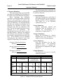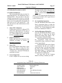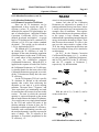
1
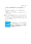
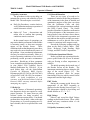
Model 3500 Manual TLD Reader with WinREMS
3500-W-O-0602
Page 5-1
Operator's Manual
5.0 Quality Assurance
The procedures in this section help you
maintain the accuracy and reliability of your
Model 3500. The main topics covered are:
!
Daily QA Procedures - routine checks to
verify calibration and proper operation of
critical electronic circuits
!
Online QC Tests - observations and
online tests to confirm that operating
conditions remain consistent
In the normal course of operations you
may notice that the performance of the Reader
is becoming erratic, or that error messages
appear on the Results Screen.
These
conditions indicate that diagnostic procedures
may need to be run to determine the source of
the problem. Some mechanical adjustments
also may be needed occasionally, either as a
result of operating conditions or as a result of
performing certain preventive maintenance
procedures. Should any of these symptoms
occur, consult the troubleshooting information
in your Model 3500 Technical Service
Manual (Publication No. 3500-0-S). If you
need further help, call the Saint-Gobain
Crystals & Detectors RMP Service
Department (800 435-5656 or 440 248-7400)
or send a FAX (440 349-6581) for assistance.
NOTE:
to avoid invalidation of your
warranty, read the Saint-Gobain Crystals &
Detectors RMP warranty statement before
attempting any repairs.
5.1 Daily QA
In the absence of abnormal operations,
few diagnostic checks are required to verify
proper operation. To insure, however, that
accurate results are being recorded, we
recommend some routine checks. You should
perform these checks daily, either at the start
of operations, or, if you are operating on a 24hour schedule, then at a specified time each
day.
5.1.1 Record Retention
There are two types of records to be
maintained: initial records of the performance
of the instrument in the form of detailed and
quantitative analyses of the glow curve data
from the Calibration Cards, and daily
recordings of the various instrument readings
(the Daily Control Chart). The former
provides a baseline for absolute confirmation
of the performance of the instrument over a
long period of time; the latter detect shorter
term drift in the instrument's operation and
may indicate the need for periodic preventive
maintenance as well as provide clues to the
reason for variations in the output records.
Record the following readings and plot
them on the Daily Control Charts: PMT
Noise, Reference Light Reading, High
Voltage, and PMT Cooler Temperatures.
5.1.2 Reader Operational Checks
Before you make any operational checks,
power up the Reader for at least 30 minutes
with gas flowing to allow temperatures to
stabilize.
The initial operating checks make use of
the Results Screen on the Reader. The
instrument monitoring data are along the left
edge of the screen (Figure 3.1). The
following procedures check for proper
functioning of devices which control critical
temperatures and the high voltage.
PMT Cooler
During the warmup period observe the
temperature of the PMT Assembly as
displayed on the Results Screen (Figure 3.1)
The temperature should be decreasing and
should stabilize at 15° C + 2° C.
High Voltage
Observe and record the High Voltage
readings on the Results Screen. These values
should each stay consistent within ±1 volt
from day to day.
5.0 Quality Assurance (cont’d)
Model 3500 Manual TLD Reader with WinREMS
Page 5-2
3500-W-O-0602
Operator's Manual
5.1 Daily QA (cont’d)
5.1.3 Reader Calibration Factor (RCF)
If the high voltage setting is changed or if
a TTP is changed, you may have to generate
a new RCF for all your calibrated TTPs.
Otherwise, we recommend that you check the
Reader Calibration Factor for one commonly
used TTP on a daily basis and record the RCF
on a Daily Control Chart. If the new RCF
varies from the previous one by more than
2%, you should seek the reason for the
change. Use the troubleshooting techniques
in the Technical Reference Manual. See
Section 6.4 Calibrate Reader in this manual
for instructions on performing the calibration.
5.1.4 Background Noise
Background noise is the reading produced
by the Reader with heat applied, but with no
TL material in the planchet. It consists of any
signal generated by contamination on the
planchet, light leaks, PMT dark current, and
stray infrared radiation.
To take a background noise reading, push
the Read Drawer all the way in with no
dosimeter in it. Then follow the normal read
procedure using the manual mode and any
standard TTP. Use a nitrogen flow to reduce
the background signal by reducing oxygeninduced TL signals.
5.2 Online QC Tests
There are several automatic procedures
available in WinREMS to enable you to
confirm that the Reader is operating
consistently. The settings for these features
are all established on the Acquisition Setup
Screen (Figure 7.24). In each case you will
set a frequency of reading, expressed as an
interval between readings, and an allowable
range. If any reported value is outside of its
acceptable range, the Reader will stop before
the next reading begins. The status of various
components of the reader at the time these
readings are take is given in Table 5.1.
Procedural instructions for editing this screen
are given in Section 4.2 Acquisition Setup.
5.2.1 PMT Noise
PMT Noise readings measure the
electronic background noise in the system.
This noise comes from light leaks,
contamination, and PMT dark current. When
this reading is taken, the Drawer should be in
the “between” position, but as far in as
possible and still not be in the “Closed”
position. The gas is flowing but is not heated,
and there is no dosimeter under the PMT. The
reading is taken for 10 seconds. In addition to
the frequency established in the Interval Field,
PMT Noise Readings are taken at the
beginning of each Group of dosimeters in
which any Interval other than ‘0' is set.
PMT Readings are reported in
picoCoulombs and generally should not
exceed the 1200. (This value is the equivalent
of a 3 mR exposure to a standard LiF chip
1/8" square by 0.015" thick.) The results
should remain reasonably consistent from day
to day.
A reading of zero may indicate one or
more of the following conditions.
1.
Analog electronics circuit input charged
positively upon initial start-up.
Model 3500 Manual TLD Reader with WinREMS
3500-W-O-0602
Page 5-3
Operator's Manual
5.2.2 Reference Light
Reference Light readings measure the
light output from an LED Reference Lights to
produce a constant light output. These
Reference Lights are located in the PMT
Assembly. The readings are taken for 10
seconds. In addition to the frequency
established in the Interval Field, Reference
Light Readings are taken at the beginning and
end of each Group of dosimeters.
Reference Light Readings are reported in
nanocoulombs. The absolute value of the
readings is not significant, but consistency of
the readings is important. Any steady drift in
the readings should be investigated to
determine its cause.
If the reading is significantly lower than
normal, the most likely cause is a dirty neutral
density filter or clean-out glass. Clean this
per the instructions in Section 3.2.1
Cleanout/Neutral Density Filter Drawer in
your Model 3500 Technical Service Manual
(Publication No. 3500-0-S).
5.0 Quality Assurance (cont’d)
5.2 Online QC Tests (cont’d)
5.2.1 PMT Noise (cont’d
Solution: Open the drawer to the Test
Light Position, wait for the PMT current
display on the PC screen to exceed 0.
2.
High Voltage interlock switch on the
Neutral Density/Cleanout Drawer is
open.
Solution: Ensure that switch closes when
the drawer is completely closed.
3.
Loose connector on High Voltage or
signal cable.
Solution: Check that Signal and HV
connectors are securely fastened to the
PMT Housing.
An excessively high or an inconsistent
reading may indicate a light leak or a
malfunctioning PMT.
REFERENCE
LIGHT
Reference LIGHT
GAS
DRAWER POSITION
TIME
PMT SHUTTER
HEAT
on
on
out
10 sec
open
off
Table 5.1
PMT NOISE
off
on
between
10 sec
open
off
Test Conditions
TLD Sample or
Dark Current
off
on
in
varies w/TTP
open
on
Model 3500 Manual TLD Reader with WinREMS
Page 5-4
3500-W-O-0602
Operator's Manual
BLANK PAGE
Model 3500 Manual TLD Reader with WinREMS
3500-W-O-0602
Page 6-1
Operator's Manual
6.0 Calibration Procedures
6.1 Introduction
This section describes the calibration
procedures for the Model 3500 with
WinREMS.
Full calibration requires
calibrating both the Reader and all the
dosimeters in the system. It is also possible to
use the system without this internal
calibration.
You may perform similar
functions manually.
6.1.1 Purpose
The purpose for calibrating TLD
Dosimeters is to ensure that all dosimeters in
a system will give essentially the same
response to a given radiation exposure.
Because of natural variations in TL material
responsiveness and in the physical mass of
manufactured TL chips, there is a variation in
response of as much as 30% (based on 3
sigma) from the mean in a population of
dosimeters.
The calibration factor for
dosimeters is called the Element Correction
Coefficient, or ECC. The ECC is used as a
multiplier with the Reader output (in
nanoCoulombs) to make the response of each
dosimeter comparable to the average response
of a designated group of dosimeters
maintained as calibration dosimeters.
The purpose for Reader calibration is to
maintain a consistent output from the Reader
over a period of time based on a convenient
local source. Such a source might be a 90Sr
source in a Harshaw Model 2210 Irradiator.
By using a set of Calibration Dosimeters and
a consistent local source, the Reader's
performance may be kept at a constant level in
spite of high voltage changes, repairs, dirt
accumulation, or long term drift. The
calibration factor for Readers is known as the
Reader Calibration Factor, or RCF. This
factor converts the raw charge data from the
Photomultiplier Tubes (in nanocoulombs) to
dosimetric units (rems, for example) or to
generic units (gU) for input to an algorithm.
The two factors are applied according to the
following formula:
6.1.2 Procedure Overview
This subsection gives an overview of the
instructions for calibrating your Reader and
dosimeters. If you are setting up your system
for the first time, it is important that you
follow these directions carefully and in the
sequence they are given. After your system is
fully operational, you may use one of these
procedures without the others.
Section 6.2 Prepare Dosimeters describes
the preparation necessary for any of the
following calibration procedures.
Section 6.3 Generate Calibration
Dosimeters describes the creation of a group
of Calibration Dosimeters usually 1-2% of the
dosimeter population, to be used for
calibrating the Reader. This procedure
establishes the Element Correction
Coefficients (ECC) of these dosimeters
without reference to a calibrated Reader.
Section 6.4 Calibrate Reader describes
the use of the Calibration Dosimeters to
establish the Reader Calibration Factor (RCF)
for each Time Temperature Profile (TTP).
Section 6.5 Calibrate Dosimeters
describes the procedure for generating the
ECCs for Field Dosimeters. You will use this
procedure to calibrate dosimeters added to
your system and to recalibrate existing
dosimeters.
Table 6.1 defines the recommended Time
Temperature Profiles for all dosimeters based
on size and material.
You should be familiar with the basic
operating procedures of the Reader and
WinREMS, specifically the information in
Sections 3.0 General Instructions and 4.0
Tutorial, before proceeding with this section.
Operational details are kept to a minimum in
order to focus on the calibration processes.
6.0 Calibration Procedures (cont'd)
Model 3500 Manual TLD Reader with WinREMS
Page 6-2
3500-W-O-0602
Operator's Manual
The following procedure will guide you
through the process of preparing dosimeters to
be read for calibration.
6.2 Prepare Dosimeters
This subsection defines a recommended
procedure for irradiating TLD Dosimeters to
be used for any of the calibration procedures.
Before beginning any calibration
procedures, you should establish a fixed fade
time for your operations for each of the
calibration procedures and record them in the
space provided below. It is important that the
time between irradiation and readout for all
dosimeters be consistent in order to keep
fading the same from one calibration to the
next. The specific length of this time is not as
important as is its consistency.
We
recommended that the fade time be no less
than thirty minutes. Otherwise, any length of
time that suits your operations is acceptable,
but it must be consistent from one time to the
next. If the dosimeters are not irradiated
simultaneously, they should be read in the
sequence in which they were irradiated.
1. Anneal Dosimeters
Anneal the Dosimeters to clear them of
all residual exposure by processing them
through a Reader with the appropriate
TTP (Table 6.1) or the equivalent
conditions in an oven.
2. Store Dosimeters
Between preparation (anneal) and
irradiation, store the dosimeters in a
subdued UV environment at a
temperature no higher than 30o C.
3. Expose Dosimeters
Expose the Dosimeters to a known
radiation source (e.g. 500 mR of 137Cs)
within two hours of annealing them.
4. Store Dosimeters
Store the dosimeters for the time
established above.
The dosimeters
should be stored in a subdued UV
environment at a temperature no higher
than 30o C.
Generate Calibration Dosimeters
fade time:
Reader Calibration Dosimeters
fade time:
Dosimeter Calibration
fade time:
5. Read Dosimeters
The dosimeters may now be read for
calibration purposes.
Material
TLD-100/600/700 (LiF:Mg,Ti)
TLD-100/600/700 (LiF:Mg,Ti)
Shape1
Rod
Chip
Cube
Size
1.0 mm diam
2.0 - 6.0 mm long
0.38 mm/0.015" thick
0.9 mm/0.035" thick
3.2 mm/0.125" square
1.0 mm sq.
Dose*
Low
High
Low
High
Low
High
50
0
50
0
50
0
50
0
50
0
50
0
PRE-HEAT
Temp
Time
TLD-100/600/700 (LiF:Mg,Ti)
ACQUIRE
Max Temp
Time
Rate
260
26.67
10
300
33.33
10
260
26.67
10
300
33.33
10
260
26.67
10
300
33.33
10
ANNEAL
Temp
Time
260
0
300
0
260
0
300
0
260
0
300
0
*
Low Dose, Radiation Protection applications, <100 mr
High Dose, Medical Therapy applications, > 1 r
Table 6.1 Standard TTP Recommendations
Model 3500 Manual TLD Reader with WinREMS
3500-W-O-0602
Page 6-3
Operator's Manual
6.0 Calibration Procedures (cont'd)
6.3 Generate Calibration Dosimeters
This section describes the specific steps
to generate Calibration Dosimeters, regardless
of type. These dosimeters typically constitute
1-2% of the entire population and are retained
at the dosimetry center for use in instrument
calibration.
1.
Prepare Dosimeters
Prepare and expose the dosimeters
according to Section 6.2 Prepare
Dosimeters.
2.
Set TTP
From the WinREMS Main Menu select
Read, TTP Setup, to bring the Time
Temperature Profile Dialog Box (Figure
7.25) into view. Set a TTP to the
conditions shown in the appropriate
column of Table 6.1.
3.
Set Acquisition Parameters
From the WinREMS Main Menu, select
Read, Acquisition Setup, to bring the
Acquisition Setup Dialog Box into view
(Figure 7.24). Set the parameters in this
box to the conditions in Table 6.2.
4.
Create Chipset File
Create a Chipset File (or use an existing
file) that includes Index, Dosimeter ID,
and TTP. (See Section 4.4 Chipset File
Setup.) Patient-related information is
unnecessary.
NOTE: It is very important that Dosimeter ID
be maintained as ECCs will be applied based
on this Dosimeter ID.
5.
Set Read Dosimeters Dialog Box
From the WinREMS Main Menu, select
Read, Start, to bring up the Read
Dosimeters Dialog Box (Figure 7.20).
Enter a unique Group ID.
In the Acquisition Setup Field, select
the Acquisition Setup established in
Step 3, and select Chipset as the Control
Mode.
Confirm that the name in the Chipset
Field matches the file you created or
selected in Step 4. If it does not, change
the name in the Files Tab of
theWorkspace Properties Dialog Box
(Figure 7.37) under the Files Tab. This
will change the name in the Read
Dosimeters Dialog Box.
You may click on the Comment
Button to add any comment you wish.
6. Read Dosimeters
Click on the Start Button and read the
entire set of dosimeters.
7. Close File and Exit
After the read process is completed, click
on the Done Button to close the dialog
box.
Table 6.2
Acquisition Setup Conditions for Generating Calibration Dosimeters
Acquisition Mode
Apply Calibration:
Export Format
PMT Noise Interval:
PMT Noise Range:
Ref Light Interval:
Ref Light Range:
Generate Calibration dosimeters
None
None
10
10 to 2000 picoCoulombs
10
Varies with instrument
Model 3500 Manual TLD Reader with WinREMS
Page 6-4
3500-W-O-0602
Operator's Manual
6.0 Calibration Procedures (cont'd)
6.3 Generate Calibration Dosimeters
(cont’d)
8.
Select Calibration Records
From the Main Menu, select Search,
Response Database to bring up the
Search Response Database Dialog Box
(Figure 7.7. Select the Group ID created
in Step 4 and select the following entries
in the designated fields
Field
Dosimeter Type
Acquisition Mode
TL Response
Display as
Standard Reports
Entry.
‘All’.
‘All’.
‘Any Element’
Standard Report.
Computed Exposure.
Click on the OK Button. This will
bring all the records in the selected group
into view. Highlight all the records in the
group by clicking on the first record and
<Shift> clicking on the last record.
(Clicking to select records requires that
the cursor be in the extreme left column,
at which time the normal arrow will turn
into a black horizontal arrow. You may
then use <Control> click and <Shift>
click as you would in any Windows
function.)
NOTE: The calibration of the entire system,
Readers and dosimeters, is based on the mean
response of the Calibration Dosimeters.
Therefore, do not use the Generate
Calibration Dosimeters procedure when there
are other Calibration Dosimeters in the same
workspace.
You may add Calibration
Dosimeters to an existing population of
Calibration Dosimeters through the Calibrate
Dosimeters feature.
9.
Set Calibration Screen
From the Main Menu, select Calibration,
Generate Calibration Dosimeters, to bring
the Generate Calibration Dosimeters
Dialog Box (Figure 7.29) into view.
Enter an Acceptable ECC range.
This value will determine the deviation
from the mean (1.0) that will be
considered acceptable for Calibration
Dosimeters. Enter the Upper and Lower
Limits of the range, for example, 0.91,
1.11 for ±10%. Generally, this range
should be narrower for Calibration
Dosimeters than for Field Dosimeters.
You may still use dosimeters which fall
outside of this range by calibrating them
as Field Dosimeters.
10. Initiate Calculations
Click on the Compute Button to calculate
the ECCs with the new range. All
records that are within the Acceptable
Range will be highlighted, those outside
the range will not. If you do not like the
results, you may change the Upper and
Lower Limits and calculate the ECCs
again. You may repeat this process until
you are satisfied with the results. For a
detailed explanation of all the fields on
this screen, see Section 7.6.1 Generate
Calibration Dosimeters.
NOTE: When performing Step 10, you must
ensure that no workstations are reading dosimeters with ECCs applied. The calibration
process takes a few seconds, and no workstations are able to access the ECC Database
during that time. If a reader attempts to
access the ECC database while it is being updated, it may "time out" and stop operations.
11. Accept Results
When you have completed the calculation
process, click on the Accept Button to
accept the results on the screen and enter
them on the ECC Database. Any
dosimeters falling outside the Acceptable
ECC Range will be marked with an
asterisk and you should remove them
from the Calibration Dosimeter set. The
accepted dosimeters will be identified as
Calibration Dosimeters on the ECC
Database.
Model 3500 Manual TLD Reader with WinREMS
3500-W-O-0602
Page 6-5
Operator's Manual
6.0 Calibration Procedures (cont'd)
4.
6.4 Calibrate Reader
This procedure establishes the Reader
Calibration Factor (RCF) for a TTP using
Calibration Dosimeters, either for a newly
defined TTP or as part of a regular QA
practice.
1.
Prepare Dosimeters
Prepare and expose a subset (five to ten
dosimeters) of the Calibration Dosimeters
according to Section 6.2 Prepare
Dosimeters.
2.
Set TTP
From the WinREMS Main Menu select
Read, TTP Setup, to bring the Time
Temperature Profile Dialog Box (Figure
7.25) into view.
Select the TTP you wish to calibrate
or set a TTP to the conditions shown in
the appropriate column of Table 6.1.
3.
Set Acquisition Parameters
From the WinREMS Main Menu, select
Read, Acquisition Setup, to bring the
Acquisition Setup Dialog Box in to view
(Figure 7.24). Set the parameters in this
box to the conditions in Table 6.3.
Create Chipset File
Create a Chipset File (or use an existing
file) that includes Index, Dosimeter ID,
and TTP. (See Section 4.4 Chipset File
Setup.) Patient-related information is
unnecessary.
NOTE: It is very important that Dosimeter ID
be maintained as ECCs will be applied based
on this Dosimeter ID.
5.
Set Read Dosimeter Dialog Box
From the WinREMS Main Menu, select
Read, Start, to bring up the Read
Dosimeters Dialog Box (figure 7.20).
Enter a unique Group ID (Name).
In the Acquisition Setup Field, select
the Acquisition Setup that you
established in Step 3 and select Chipset
as the Control Mode.
Confirm that the name in the Chipset
Field matches the file you created or
selected in Step 4. If it does not, change
the name in the Workspace Properties
Dialog Box (Figure 7.37) under the Files
Tab. This will change the name in the
Read Dosimeters Dialog Box.
You may click on the Comment
Button to add any comment you wish.
Table 6.3
Acquisition Setup Conditions for Calibrating the Reader
Acquisition Mode
Apply Calibration:
Export Format
PMT Noise Interval:
PMT Noise Range:
Ref Light Interval:
Ref Light Range:
Calibrate Reader
Apply ECC
None
1
10 to 2000 picoCoulombs
1
Varies with instrument
Model 3500 Manual TLD Reader with WinREMS
Page 6-6
3500-W-O-0602
Operator's Manual
6.0 Calibration Procedures (cont'd)
6.4 Calibrate Reader (cont'd)
6.
Read Dosimeters
Click on the Start button and read the
entire set of dosimeters.
7.
Close File and Exit
After the read process is completed, click
on the Done Button to close the dialog
box.
8.
Select Calibration Records
From the Main Menu, select Search,
Response Records to bring up the Search
Response Database Dialog Box
(Figure 7.8). Select the Group ID created
in Step 4 and select the following entries
in the designated fields.
Field
Entry
Dosimeter Type
‘All’.
Acquisition Mode
‘All’.
TL Response
‘Any Element’
Display as
Standard Report.
Standard Reports
Computed Exposure.
Click on the OK Button. This will
bring all the records in the selected group
into view. Highlight all the records in the
group by clicking on the first record and
<Shift> clicking on the last record.
(Clicking to select records requires that
the cursor be in the extreme left column,
at which time the normal arrow will turn
into a black horizontal arrow. You may
then use <Control> click and <Shift>
click as you would in any Windows
function.)
9.
Set Calibration Parameters
From the Main Menu, select Calibration,
Reader Calibration, to bring up the
Reader Calibration Dialog Box
(Figure 7.31).
In the Irradiation Field, select the
dose to which the Calibration Dosimeters
were exposed in Step 1.
In the TTP Title Field, select the
TTP selected in Step 2.
In the units field, select the unit of
measure for the Irradiation. These units
will then be applied to all future readings
taken with this TTP when the RCF is
applied.
10. Calculate RCF
Click on the Compute Button to
calculate the RCFs. For a detailed
explanation of all the fields on this
screen, see Section 7.6.2 reader
Calibration.
11. Accept Results
Click on the Accept Button to enter the
RCFs in the TTP Files. If you do not
want to accept the computed RCF, you
may click on the Cancel Button.
Model 3500 Manual TLD Reader with WinREMS
3500-W-O-0602
Page 6-7
Operator's Manual
6.0 Calibration Procedures (cont'd)
6.5 Calibrate Dosimeters
This section describes the procedure for
generating the ECCs for Dosimeters from a
calibrated TTP. This procedure is the same
whether the dosimeters are new or are being
re-calibrated as part of a regular QA program.
In the case of a re-calibration, the system will
make the new ECC the current ECC. You
may also mix new and used dosimeters in the
same batch.
1.
Check TTP Calibration
Confirm that you have a calibrated TTP
with values appropriate for the type of
dosimeters being calibrated. (See Table
6.1.) If not, calibrate one as described in
Section 6.4 Calibrate Reader.
2.
Prepare Dosimeters
Prepare and expose the dosimeters to be
calibrated according to Section 6.2
Dosimeter Preparation.
3.
Check TTP
From the WinREMS Main Menu, select
Read, TTP Setup to bring the Time
Temperature Profile Dialog Box (Figure
7.25) into view. Select the TTP that you
established in Step 1.
4.
Create Chipset File
Create a Chipset File (or use an existing
file) that includes Index, Dosimeter ID,
and TTP. (See Section 4.4 Chipset File
Setup.) Patient-related information is
unnecessary.
NOTE: It is very important that Dosimeter ID
be maintained as ECCs will be applied based
on this Dosimeter ID.
5.
Set Acquisition Parameters
From the WinREMS Main Menu, select
Read, Acquisition Setup, to bring the
Acquisition Setup Dialog Box into view
(Figure 7.24). Set the parameters in this
box to the conditions in Table 6.4.
6.
Set Read Dosimeter Dialog Box
From the WinREMS Main Menu, select
Read, Start, to bring up the Read
Dosimeters Dialog Box (Figure 7.20).
Enter a unique Group ID (Name).
In the Acquisition Setup Field, select
the Acquisition Setup that you
established in Step 4, and select Chipset
as the Control Mode.
Confirm that the name in the Chipset
Field matches the file you created or
selected in Step 4. If it does not, change
the name in the Workspace Properties
Dialog Box (Figure 7.37) under the Files
Tab. This will change the name in the
Read Dosimeters Dialog Box.
You may click on the Comment
Button to add any comment you wish.
Table 6.4
Acquisition Setup Conditions for Calibrating Dosimeters
Acquisition Mode
Apply Calibration:
Export Format
PMT Noise Interval:
PMT Noise Range:
Ref Light Interval:
Ref Light Range:
Calibrate Dosimeters
Apply RCF
None
10
10 to 2000 picoCoulombs
10
Varies with instrument
Model 3500 Manual TLD Reader with WinREMS
Page 6-8
3500-W-O-0602
Operator's Manual
6.0 Calibration Procedures (cont'd)
6.5 Calibrate Dosimeters (cont’d)
7.
Read Dosimeters
Click on the Start button and read the
entire set of dosimeters.
8.
Close File and Exit
After the read process is completed, click
on the Done Button to close the dialog
box.
9.
Select Calibration Records
From the Main Menu, select Search,
Response Records to bring up the Search
Response Database Dialog box
(Figure 7.8). Enter the Group ID created
in Step 5 and select the following entries
in the designated fields.
Field
Dosimeter Type
Acquisition Mode
TL Response
Display as
Standard Reports
Entry.
‘All’.
‘All’.
‘Any Element’
Standard Report.
Computed Exposure.
Click on the OK Button. This will
bring all the records in the selected group
into view. Highlight all the records in the
group by clicking on the first record and
<Shift> clicking on the last record.
(Clicking to select records requires that
the cursor be in the extreme left column,
at which time the normal arrow will turn
into a black horizontal arrow. You may
then use <Control> click and <Shift>
click as you would in any Windows
function.)
10. Get Calibration Dialog Box
From the Main Menu, select Calibration,
Dosimeter Calibration, to bring the
Dosimeter Calibration Dialog Box into
view (Figure 7.31).
11. Set Calibration Parameters
In the Irradiation Field, select the
exposure used to irradiate the dosimeters
in Step 2.
Click on the arrow in the Mark as
Field and select ‘Field’.
Enter an acceptable ECC range.
This value will determine the deviation
from the mean (1.0) of the Calibration
Dosimeters that will be considered
acceptable for the Field Dosimeters.
Enter it as the Upper and Lower Limits
for each position, for example, 0.77 and
1.43. Dosimeters which fall outside of
this range will be flagged as Bad
Dosimeters on the database and will not
be issuable as Field Dosimeters.
12. Initiate Calculations
Click on the Compute Button to calculate
the ECC values. All the acceptable
records will be highlighted in the upper
portion of the screen.
Note that if the dosimeters being
calibrated are not of the same
specification as the Calibration
Dosimeters, the ECCs for one or more
chips may not center around 1.0, as
would be the case with dosimeters with
the same specification. This may require
that you repeat Steps 10 and 11 with
different values for the Acceptable ECC
Range.
NOTE: When performing Step 11, you must
ensure that no workstations are reading
dosimeters with ECCs applied.
The
calibration process takes a few seconds, and
no workstations are able to access the ECC
Database during that time. If a reader
attempts to access the ECC database while it
is being updated, it may "time out" and stop
operations.
13. Accept Values
When you are satisfied with the results,
click on the Accept Button to apply the
data to the ECC Database.
Model 3500 Manual TLD Reader with WinREMS
3500-W-O-0602
Page 6-9
Operator's Manual
6.0 Calibration Procedures (cont’d)
6.6 Calibration Methodology
6.6.1 Element Correction Coefficients
Since not all TL dosimeters can be
manufactured to have exactly the same TL
efficiency (where TL efficiency (TLE) is
defined as the emitted TL light intensity per
unit of absorbed dose), individual Element
Correction Coefficients (ECCs) must be
defined, developed and applied. A typical
batch of TL dosimeters has a variation in TL
efficiency of 10-15% (one relative standard
deviation). This spread can be reduced to
1-2% by application of ECCs.
The method of ECC generation is based
on relating the TL efficiency of each TL
dosimeter of the entire dosimeter population
(Field Dosimeters) to the mean TL efficiency
of a small subset of this population that is
used only for calibration purposes
(Calibration Dosimeters). When the ECC is
applied to the response of each of the Field or
the Calibration Dosimeters, its TL efficiency
is virtually identical to the mean value of the
Calibration Dosimeters group and, as a result,
all the TL dosimeters ideally have the same
TL efficiency.
Let the TL Response (TLR) of a specific
TL dosimeter be defined as the measured
quantity that results from subjecting the
dosimeter to one unit of a given ionizing
radiation. The terms "dose," "exposure," and
"dose equivalent" are intentionally not used
for reasons that will become clear later in this
section. The unit in which the measured
quantity is expressed depends on the means
that are used to detect the emitted TL photons.
If we could count every single photon emitted
by the TLD and express the units of the
ionizing radiation in terms of dose, the TL
Response would be equal to the TL efficiency.
Normally such a relationship is not the case;
the measured quantity is usually expressed in
units of charge. The TL response of the
dosimeter is, in general, proportional to the
TL efficiency, i.e.:
(1)
when k is the proportionality constant.
Assume now that all the Calibration
Dosimeters are subjected to a quantity L of
ionizing radiation from a given source, where
L can be expressed in any convenient unit, for
example, time of irradiation. This requires
that, for each dosimeter, the geometry relative
to the source is kept constant, and the
radiation field is penetrating enough to deposit
energy in the entire dosimetric volume. Note
that, because the measured TL effect is the
sum over the entire sensitive volume of the
TLD, the energy deposition profile does not
have to be uniform as long as it is similar for
each dosimeter.
Let ECCj be the Element Correction
Coefficient for Dosimeter j (j=1,2....,m, where
m is the number of Calibration Dosimeters),
and let TLEj and TLRj be the TL efficiency
and the TL response of Dosimeter j,
respectively. By definition then
(2)
when:
(3)
With the aid of (1), (2) and (3) can be
written in the form
(4)
when:
(5)
6.0 Calibration Procedures (cont'd)
Model 3500 Manual TLD Reader with WinREMS
Page 6-10
3500-W-O-0602
Operator's Manual
6.6 Calibration Methodology (cont'd)
6.6.1 Element Correction Coefficients
(cont'd)
Note that the implicit assumption in
writing (4) and (5) is that the Reader response
to TL photons did not change during the
measurement of the entire population of the
Calibration Dosimeters; i.e., k remains
constant during the entire TL readout process.
Since this step is the most critical to the
success of generating true ECCs, it is
important to perform it in a relatively short
period of time. It is also important to ensure
the stability of the light detection and the
heating subsystems, which is done by frequent
Reference Light measurements and glow
curve analyses, respectively, to ensure
complete readout. It is convenient to express
(4) and (5) in terms of the quantity that is
reported by the TLD Reader (charge). If Qj is
defined as the charge reported by the Reader
for dosimeter j following its subjection to n
irradiation units, then TLRj and <TLR> can
be written in the form
(6)
and
(7)
when
(8)
Using (6), (7), and (8), (4) can be written
in the form:
(9)
when <Q> is given by (8).
Once ECCs are established for the
Calibration Dosimeters, each one has virtually
the same TL efficiency and any statistically
significant subset of Calibration Dosimeters
can be used to generate ECCs for Field
Dosimeters.
Let q'j be defined as the charge reported
by the Reader for Field Dosimeter j following
its subjection to n irradiation units. Assume
that a subset of the Calibration Dosimeters
was also exposed at the same time and read
together with the Field Dosimeters. Since the
time that <Q> was generated, the Reader may
have changed its response to TL photons as a
result of intentional or accidental change in
the High Voltage power supply setting,
replacement of damaged Photomultiplier
Tubes, replacement of IR filters or
accumulation of dirt on the IR filters. Assume
that the response of the Reader changed by a
factor of C. Since this change will affect all
of the TL dosimeters equally, then
(10)
and
(11)
when qj is the charge that would have been
reported by Field Dosimeter j at the time that
<Q> was generated, and <Q>' is the average
reported charge from the Calibration
Dosimeters that were exposed and read
together with the Field Dosimeters whose
Element Correction Coefficients have to be
generated.
Similar to (9), Element Correction
Coefficients ECCj for Field Dosimeters are
defined as
(12)
Model 3500 Manual TLD Reader with WinREMS
3500-W-O-0602
Page 6-11
Operator's Manual
6.0 Calibration Procedures (cont'd)
6.6 Calibration Methodology (cont'd)
6.6.1 Element Correction Coefficients
(cont'd)
Note that the ECC values for the Field
Dosimeters would be the same whether
generated at the same time as the Calibration
Dosimeters' ECCs or at another time, since the
C values from (10) and (11) would have been
canceled out in (12).
Once ECCs for the Field Dosimeters have
been generated and applied, their TL
efficiency (sensitivity) is virtually equal to the
mean TL efficiency of the Calibration
Dosimeters, and, as a result, all the dosimeter
population will have virtually the same TL
efficiency, as shown in Figure 6.1. When new
dosimeters are added to the population, their
TL efficiency can be set to be virtually equal
to the existing dosimeter population by
generating ECCs for the new dosimeters. The
only parameter which must remain constant is
the inherent sensitivity of the Calibration
Dosimeters that are being used. Extensive
testing by Saint-Gobain Crystals & Detectors
RMP and by our customers has shown,
however, that the TL dosimeters used here can
be subjected to hundreds of reuse cycles
without any noticeable change in their TL
efficiency.
Note that the radiation source used for
generating the ECCs for the Field Dosimeters
does not have to be the same one used for
generating the ECCs for the Calibration
Dosimeters, provided that a subset of
Calibration Dosimeters is exposed to the same
radiation field as the Field Dosimeters whose
ECCs are being generated. Also note that
there is no need for the dosimeters to be
mounted in their holders during irradiation,
since the only purpose of this irradiation is to
induce an excitation in the TL material, which
will result in a measurable TL signal that is
proportional to the TL efficiency of the TL
dosimeter. Furthermore, no attempt has been
made yet to correlate this TL response to any
kind of "real" dose units.
Figure 6.1 Internal Calibration of a TLD System
Model 3500 Manual TLD Reader with WinREMS
Page 6-12
3500-W-O-0602
Operator's Manual
6.0 Calibration Procedures (cont'd)
6.6 Calibration Methodology (cont'd)
6.6.2 Reader Calibration Factors
The only part of the system that is likely
to become unstable over long periods of time
is the TLD Reader. The radiation sources are
usually stable, or at least it is relatively easy
to apply correction factors to account for the
decay of the radioactive material. The TL
dosimeters under controlled operational
conditions will not change their TL efficiency,
and the irradiation geometry can be easily
maintained.
For the Reader to be able to consistently
convert stored TL information to measurable
electric signals (charge), it is convenient to
express the ratio between the average TL
response of the Calibration Dosimeters and
the delivered radiation quantity L in terms of
one variable. Since the numerical value of
this variable will be mainly dependent on the
condition of the Reader at a given date and
time, it is appropriate to call this variable
Reader Calibration Factor (RCF). The value
of the RCF, although not expressed yet in
terms of "real" dose units, provides the main
link between the TL response in terms of
charge or counts and the absorbed dose or
dose equivalent in terms of Gray or Seivert,
respectively.
The RCF is defined as
(13)
where <Q> is the average reported charge of
a set of Calibration Dosimeters exposed to a
known quantity of radiation L.
As discussed in the previous section, the
radiation quantity L can be expressed in any
convenient units. For this discussion, the unit
gU (generic unit) is defined as the unit which
expresses the quantity L. For example, 1 gU
can be equal to the amount of irradiation
delivered during a period of one second by a
specific source with specific geometry to a
dosimeter located at a specific distance from
the source. Since the definition of the unit gU
is somewhat arbitrary, once it is defined for a
specific source and geometry, it will have
meaning only for this source, here referred to
as the Local Source or Reference Source.
There is some similarity between the gU
and the conventional units in the sense that gU
is the unit of the quantity L in a similar way as
the Roentgen (R) is the unit of exposure and
the Gray and the Seivert are the units of
absorbed dose and dose equivalent,
respectively. Unlike the conventional units,
however, which have universal meaning, the
amount of radiation which corresponds to one
gU is completely arbitrary and depends on the
way gU is defined. Since the purpose of a
dosimetry system is to make possible the
measurement of absorbed dose or dose
equivalent, the rest of this section is devoted
to the question of how to establish the link
between gU and Gray, Sievert, rad, or rem.
From the discussion so far, it is clear that
in order to obtain a meaningful RCF, it must
be possible to accurately reproduce the
irradiations of the calibration dosimeters. One
way to do this is to use periodically calibrated
sources that are traceable to the NIST or
another recognized standards body. These
sources are usually located at a special testing
or calibration laboratory such as Pacific
Northwest Laboratories of Battelle. In this
case the quantity L will be the exposure (or
whatever quantity the source is calibrated for)
and the gU will be the Roentgen (R) or any
other corresponding unit.
Sending the
dosimeters to a special laboratory creates
many inconveniences, however: loss of time,
increased expenses and planning
requirements, and danger of damage or
exposure of the dosimeters during shipping.
It is also difficult to expose dosimeters on
short notice when a new RCF has to be
generated (when a PMT has been replaced, for
example). In short, this approach provides no
significant advantage over the use of a local
Model 3500 Manual TLD Reader with WinREMS
3500-W-O-0602
Page 6-13
Operator's Manual
6.0 Calibration Procedures (cont'd)
6.6 Calibration Methodology (cont'd)
6.6.2 Reader Calibration Factors (cont'd)
reference source for generating the RCF, since
the RCF is a relative quantity.
If we return now to (12), the ECCs for the
Field Dosimeters can be expressed in terms of
the RCF using (13):
similar way that the RCF value provides the
link between the internal units of the Reader
(counts or charge) and the local source. For
charge integration systems, the RCF is
expressed in units of nC/gU; the quantity
RCF*K is expressed in terms of nC/Sievert
and provides the link between the internal
units of the Reader and the dose Dj.
(17)
(14)
From (14), L can be expressed in terms of the
RCF, ECC and q :
(15)
Once ECCs for Calibration Dosimeters
and Field Dosimeters have been generated,
and the local unit, gU, has been defined, the
link to a calibrated source located at a
calibration laboratory should be established.
The calibration laboratory is able to perform
the irradiations and report the delivered
quantity in terms of the desired quantity (for
example, dose, dose-equivalent, exposure,
etc.). A subset of the Calibration Dosimeters
in their holders (if applicable) is exposed to
dose D from a calibrated source (for example,
137
Cs) and read out.
The Reader reports its findings in units of
gU using (15); however, since the value of D
as reported by the calibration laboratory is
known, one can establish the following
relations between the local units, gU, and the
dose in units of Gy (or any other quantity with
the appropriate unit):
(16)
for the gU to dose conversion factor.
Note that K is expressed in units of
gU/Gy and provides the link between the local
source and the calibration laboratory in a
If the Reader is routinely calibrated
directly in terms of "nC/Gy", then there is no
need to establish the relationship shown in
(16). Note that since the definition of the gU
unit is based on exposing some Calibration
Dosimeters to the local source following a
reproducible procedure, the time intervals
between preparation and irradiation and
between irradiation and readout are not
important as long as they are kept constant. If
it is not possible to keep the fading constant,
it may be eliminated by removing the low
temperature peaks.
Also note that the time interval between
irradiation at the calibration laboratory and
readout does not have to be the same as the
time interval used for generating the RCF.
The reason is that the gU is defined for a
specific time interval between irradiation and
readout, and, as long as this time interval is
kept constant, the definition of gU will not
change. Fading corrections have to be applied
(or the low temperature peaks have to be
removed) only if the values of K are used to
calculate the reported dose from a Field
dosimeter. In this case, the difference in
fading created by the difference between the
two time intervals (the interval between field
irradiation and readout and the interval
between laboratory irradiation and readout)
must be corrected. This may be done either
mathematically or by removing the low
temperature peaks.
Model 3500 Manual TLD Reader with WinREMS
Page 6-14
3500-W-O-0602
Operator's Manual
BLANK PAGE