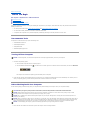
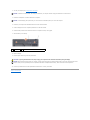
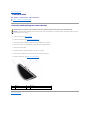
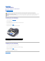
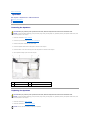
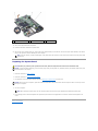
1
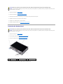
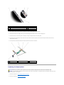
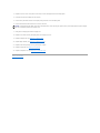
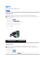
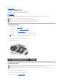
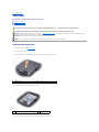
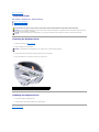
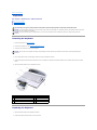
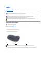
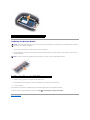
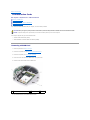
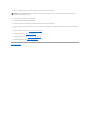
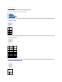
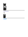
Dell™ Inspiron™ 1420/Dell Vostro™ 1400 Service Manual
Before You Begin
Display
Internal Card With Bluetooth® Wireless Technology
Camera Module
Optical Drive
Palm Rest
Hard Drive
Fan
Memory
Microprocessor Thermal-Cooling Assembly
Modem
Microprocessor Module
Coin-Cell Battery
System Board
Keyboard Cover
Speakers
Keyboard
Flashing the BIOS
Communication Cards
Pin Assignments for I/O Connectors
Intel® Turbo Memory
Notes, Notices, and Cautions
NOTE: A NOTE indicates important information that helps you make better use of your computer.
NOTICE: A NOTICE indicates either potential damage to hardware or loss of data and tells you how to avoid the problem.
CAUTION: A CAUTION indicates a potential for property damage, personal injury, or death.
NOTE: The appearance of your computer may vary from what is shown in this document.
Information in this document is subject to change without notice.
© 2007 Dell Inc. All rights reserved.
Reproduction in any manner whatsoever without the written permission of Dell Inc. is strictly forbidden.
Trademarks used in this text: Dell, the DELL logo, Inspiron and Vostro are trademarks of Dell Inc.; Intel is a registered trademark of Intel Corporation; Microsoft, Windows, and
Windows Vista are either trademarks or registered trademarks of Microsoft Corporation in the United States and/or other countries; Bluetooth is a registered trademark owned by
Bluetooth SIG, Inc. and is used by Dell under license.
Other trademarks and trade names may be used in this document to refer to either the entities claiming the marks and names or their products. Dell Inc. disclaims any
proprietary interest in trademarks and trade names other than its own.
June 2007 Rev. A00
Back to Contents Page
Before You Begin
Dell™ Inspiron™ 1420/Dell Vostro™ 1400 Service Manual Recommended Tools
Turning Off Your Computer
Before Working Inside Your Computer
This section provides procedures for removing and installing the components in your computer. Unless otherwise noted, each procedure assumes that the
following conditions exist:
l
You have performed the steps in Turning Off Your Computer and Before Working Inside Your Computer.
l
You have read the safety information in the Dell™ Product Information Guide.
l
A component can be replaced or—if purchased separately—installed by performing the removal procedure in reverse order.
Recommended Tools
The procedures in this document may require the following tools:
l
Small flat-blade screwdriver
l
Small Phillips screwdriver
l
Small plastic scribe
l
Flash BIOS update program CD
Turning Off Your Computer
NOTICE: To avoid losing data, save and close all open files and exit all open programs before you turn off your computer.
1.
Shut down the operating system:
a.
Save and close all open files and exit all open programs.
b.
Click the Windows Vista Start button
, click the arrow in the lower-right corner of the Start menu as shown below, and then click Shut Down.
The computer turns off after the operating system shutdown process is complete.
2.
Ensure that the computer and all attached devices are turned off. If your computer and attached devices did not automatically turn off when you shut
down your operating system, press and hold the power button for about 4 seconds to turn them off.
Before Working Inside Your Computer
Use the following safety guidelines to help protect your computer from potential damage and to help to ensure your own personal safety.
CAUTION: Before you begin any of the procedures in this section, follow the safety instructions in the Product Information Guide.
NOTICE: Handle components and cards with care. Do not touch the components or contacts on a card. Hold a card by its edges or by its metal
mounting bracket. Hold a component such as a processor by its edges, not by its pins.
NOTICE: Only a certified service technician should perform repairs on your computer. Damage due to servicing that is not authorized by Dell is not
covered by your warranty.
NOTICE: When you disconnect a cable, pull on its connector or on its pull-tab, not on the cable itself. Some cables have connectors with locking tabs; if
you are disconnecting this type of cable, press in on the locking tabs before you disconnect the cable. As you pull connectors apart, keep them evenly
aligned to avoid bending any connector pins. Also, before you connect a cable, ensure that both connectors are correctly oriented and aligned.
NOTICE: To avoid damaging the computer, perform the following steps before you begin working inside the computer.
1.
Ensure that the work surface is flat and clean to prevent the computer cover from being scratched.
2.
Turn off your computer (see Turning Off Your Computer).
NOTICE: To disconnect a network cable, first unplug the cable from your computer and then unplug the cable from the network device.
3.
Disconnect all telephone or network cables from the computer.
NOTICE: To avoid damaging the system board, you must remove the main battery before you service the computer.
4.
Disconnect your computer and all attached devices from their electrical outlets.
5.
Close the display and turn the computer upside-down on a flat work surface.
6.
Slide the battery release latches toward the sides of the computer until they are engaged.
7.
Slide the battery out of the bay.
1
battery
2
battery release latches (2)
8.
Open the display.
9.
Press the power button to ground the system board.
CAUTION: To guard against electrical shock, always unplug your computer from the electrical outlet before opening the display.
NOTICE: Before touching anything inside your computer, ground yourself by touching an unpainted metal surface, such as the metal at the back of the
computer. While you work, periodically touch an unpainted metal surface to dissipate static electricity, which could harm internal components.
10.
Remove any installed cards from the ExpressCard slot and the 8-in-1 memory card reader.
Back to Contents Page
Back to Contents Page
Flashing the BIOS
Dell™ Inspiron™ 1420/Dell Vostro™ 1400 Service Manual 1.
Download the BIOS utility from the Dell Support website at support.dell.com and save it to your desktop.
2.
After the download completes, double-click the BIOS utility file.
3.
In the Dell BIOS Flash window, click Continue.
4.
When the reboot message appears, click OK and wait for the computer to restart.
Back to Contents Page
Back to Contents Page
Internal Card With Bluetooth® Wireless Technology
Dell™ Inspiron™ 1420/Dell Vostro™ 1400 Service Manual Removing and Replacing Internal Card With Bluetooth® Wireless Technology
CAUTION: Before you begin any of the procedures in this section, follow the safety instructions in the Product Information Guide.
NOTICE: To help prevent damage to the system board, you must remove the battery from the battery bay before you begin working inside the
computer.
Removing and Replacing Internal Card With Bluetooth® Wireless Technology
CAUTION: Before performing the following procedures, follow the safety instructions in your Product Information Guide.
NOTICE: To avoid electrostatic discharge, ground yourself by using a wrist grounding strap or by periodically touching a connector on the back panel of
the computer.
If you ordered an internal card with Bluetooth wireless technology with your computer, it is already installed.
1
1.
Follow the procedures in Before You Begin.
2.
Remove the memory module cover (see Memory).
metal clip
2
internal card with Bluetooth wireless technology
3
captive screw
NOTICE: Be careful when removing the card to avoid damaging the card, card cable, or surrounding components.
3.
Loosen the captive screw to remove the card carrier.
4.
Gently slide the card out from underneath the metal clips.
5.
Lift the card from the compartment, ensuring that you do not pull on the card cable with excessive force.
6.
Disconnect the card from the card cable.
7.
Connect the replacement card to the card cable.
8.
Slide the card underneath the metal clips.
9.
Tighten the captive screw to secure the card carrier.
Back to Contents Page
Back to Contents Page
Camera Module
Dell™ Inspiron™ 1420/Dell Vostro™ 1400 Service Manual Removing and Replacing the Camera Module
Removing and Replacing the Camera Module
CAUTION: Before you perform any of the procedures in this section, follow the safety instructions in the Product Information Guide.
NOTICE: To avoid electrostatic discharge, ground yourself by using a wrist grounding strap or by periodically touching an unpainted metal surface, such
as the back panel on the computer.
1.
Follow the instructions in Before You Begin.
2.
Remove the display bezel (see Removing the Display Bezel).
3.
Lift the cable securing tab and gently pull the camera module cable from the connector.
4.
Remove the two M2 x 3-mm screws securing camera module to the display assembly.
5.
Gently lift the camera module.
6.
Install the replacement camera and tighten the two M2 x 3-mm screws.
7.
Insert the camera module cable in the connector and press down the securing tab.
8.
Replace the display bezel (see Replacing the Display Bezel).
1
display
2
screws (2)
3
camera
4
camera module
Back to Contents Page
Back to Contents Page
Coin-Cell Battery
Dell™ Inspiron™ 1420/Dell Vostro™ 1400 Service Manual Removing the Coin-Cell Battery
Replacing the Coin-Cell Battery
CAUTION: Before you begin any of the procedures in this section, follow the safety instructions in the Product Information Guide.
NOTICE: To avoid electrostatic discharge, ground yourself by using a wrist grounding strap or by periodically touching an unpainted metal surface (such
as a connector on the back of the computer).
NOTICE: To help prevent damage to the system board, you must remove the battery from the battery bay before you begin working inside the
computer.
Removing the Coin-Cell Battery
1.
Follow the procedures in Before You Begin.
2.
Turn the computer over.
3.
Loosen the captive screws on the coin-cell battery cover and remove the cover.
4.
Remove the modem (see Modem).
5.
Disconnect the coin-cell battery cable from the system board.
1
coin-cell battery
6.
2
battery cable connector
Lift the battery out.
Replacing the Coin-Cell Battery
1.
Connect the coin-cell battery cable to the system board.
2.
Place the coin-cell battery on the system board in the location marked
3.
Replace the modem (see Modem).
4.
Replace the cover and tighten the captive screws.
Back to Contents Page
.
Back to Contents Page
Microprocessor Module
Dell™ Inspiron™ 1420/Dell Vostro™ 1400 Service Manual Removing the Microprocessor Module
Replacing the Microprocessor Module
Removing the Microprocessor Module
CAUTION: Before you perform any of the procedures in this section, follow the safety instructions in the Product Information Guide.
NOTICE: To avoid electrostatic discharge, ground yourself by using a wrist grounding strap or by periodically touching an unpainted metal surface, such
as the back panel on the computer.
NOTICE: Handle the microprocessor module with care. Hold the microprocessor module by its edges and do not touch the processor die (the small chip
in the center of the module).
1.
Follow the instructions in Before You Begin.
2.
Loosen the three captive screws securing the microprocessor module cover, then remove the cover and set it aside.
1
microprocessor module cover
2
captive screw (3)
NOTICE: To ensure maximum cooling for the microprocessor, do not touch the heat transfer areas on the microprocessor thermal-cooling assembly. Oils
in your skin can reduce the heat transfer capability of the thermal pads.
3.
Remove the microprocessor thermal-cooling assembly (see Removing the Microprocessor Thermal-Cooling Assembly).
NOTICE: To avoid damaging the microprocessor, hold the screwdriver so that it is perpendicular to the microprocessor module when turning the cam
screw.
4.
To loosen the ZIF-socket cam lock, use a small, flat-blade screwdriver and rotate the ZIF-socket cam screw counterclockwise until it comes to the cam
stop.
NOTE: The ZIF-socket cam screw secures the microprocessor module to the system board.
1
microprocessor module
2
ZIF-socket
3
ZIF-socket cam screw
NOTICE: When removing the microprocessor module, pull the module straight up and out of the ZIF-socket. Exercise care not to bend the pins on the
microprocessor module.
NOTE: The microprocessor module and the ZIF-socket illustration shown may not exactly resemble the ones in your system.
5.
Lift the microprocessor module straight up and out of the ZIF-socket.
Replacing the Microprocessor Module
CAUTION: Before you perform any of the procedures in this section, follow the safety instructions in the Product Information Guide.
NOTICE: To avoid electrostatic discharge, ground yourself by using a wrist grounding strap or by periodically touching an unpainted metal surface, such
as the back panel on the computer.
NOTE: When installing a new microprocessor module, use the thermal cooling assembly or thermal pad that came with the module, if applicable.
1.
Follow the instructions in Before You Begin.
NOTICE: Handle the microprocessor module with care. Hold the microprocessor module by its edges and do not touch the processor die (the small chip
in the center of the module).
2.
Follow the instructions in Removing the Microprocessor Module.
NOTICE: Ensure that the cam lock is in the fully open position before seating the microprocessor module. Seating the microprocessor module properly in
the ZIF socket does not require force. A microprocessor module that is not properly seated can result in an intermittent connection or permanent
damage to the microprocessor and ZIF socket.
3.
Align the pin-1 corner of the new microprocessor module with the pin-1 corner of the ZIF socket, and insert the microprocessor module.
NOTE: The pin-1 corner of the microprocessor module has a triangle that aligns with the triangle on the pin-1 corner of the ZIF socket.
NOTE: Gently press down on the substrate on which the processor die is mounted to ensure the microprocessor module is properly seated.
When the microprocessor module is properly seated, all four corners of the module are aligned at the same height. If one or more corners of the module
is higher than the others, the module is not properly seated.
NOTICE: To avoid damaging the microprocessor, hold the screwdriver so that it is perpendicular to the microprocessor module when turning the cam
screw.
4.
To tighten the ZIF-socket cam lock and secure the microprocessor module to the system board, use a small, flat-blade screwdriver and rotate the ZIFsocket cam screw clockwise until it comes to the cam stop.
5.
Replace the microprocessor thermal-cooling assembly (see Replacing the Microprocessor Thermal-Cooling Assembly).
6.
Replace the microprocessor module cover.
7.
Update the BIOS using a flash BIOS update program floppy disk or CD. For instructions on how to flash the BIOS, see Flashing the BIOS.
Back to Contents Page
Back to Contents Page
Microprocessor Thermal-Cooling Assembly
Dell™ Inspiron™ 1420/Dell Vostro™ 1400 Service Manual Removing the Microprocessor Thermal-Cooling Assembly
Replacing the Microprocessor Thermal-Cooling Assembly
Removing the Microprocessor Thermal-Cooling Assembly
CAUTION: Before you perform any of the procedures in this section, follow the safety instructions in the Product Information Guide.
NOTICE: To avoid electrostatic discharge, ground yourself by using a wrist grounding strap or by periodically touching an unpainted metal surface, such
as the back panel on the computer.
1.
Follow the instructions in Before You Begin.
2.
Loosen the three captive screws securing the microprocessor module cover, then remove the cover and set it aside.
1
microprocessor module cover
3.
1
2
captive screws (3)
Loosen the four captive screws securing the microprocessor thermal- cooling assembly to the system board, then carefully lift the assembly straight out
of the computer.
microprocessor thermal-cooling assembly
2
screws (4)
Replacing the Microprocessor Thermal-Cooling Assembly
CAUTION: Before you perform any of the procedures in this section, follow the safety instructions in the Product Information Guide.
NOTICE: To avoid electrostatic discharge, ground yourself by using a wrist grounding strap or by periodically touching an unpainted metal surface, such
as the back panel on the computer.
1.
Follow the instructions in Before You Begin.
2.
Follow the instructions in Replacing the Microprocessor Module.
3.
Align the four captive screws on the new microprocessor thermal-cooling assembly with the screw holes on the system board.
4.
Tighten the four captive screws in the order that they are numbered to secure the microprocessor thermal-cooling assembly to the system board.
5.
Replace the microprocessor module cover.
Back to Contents Page
Back to Contents Page
Display
Dell™ Inspiron™ 1420/Dell Vostro™ 1400Service Manual Removing the Display Assembly
Replacing the Display Assembly
Removing the Display Bezel
Replacing the Display Bezel
Removing the Display Panel
Replacing the Display Panel
Removing the Display Assembly
CAUTION: Before you perform any of the procedures in this section, follow the safety instructions in the Product Information Guide.
NOTICE: To avoid electrostatic discharge, ground yourself by using a wrist grounding strap or by periodically touching an unpainted metal surface, such
as the back panel on the computer.
1.
Follow the instructions in Before You Begin.
2.
Remove the keyboard cover (see Removing the Keyboard Cover).
3.
Remove the keyboard (see Removing the Keyboard).
4.
Remove the left and right hinge covers using a plastic scribe to pry it out.
5.
Ensure that the display is opened all the way (150 degrees).
1
display cable pull-tab
2
Mini-Card antenna cables
6.
Use the pull-tab to disconnect the display cable from the system board.
7.
Remove the Mini-Card antenna cables from the cards.
8.
Remove the Mini-Card antenna cables from the cable guide.
9.
Remove the screw from the media buttons board.
10.
Slide the media buttons board left to release it from the grips and lift the media buttons board.
1
media buttons board
1
screws (2)
1
screws (2)
11.
12.
2
2
2
main battery bay
screw
3
back of the system
3
grips (5)
bottom of the system
3
hinge covers (2)
Remove the four M2.5 x 5-mm screws (one on each side of the main battery bay and one below each hinge cover) that connect the display assembly to
the computer.
Lift the display assembly straight up and out of the computer.
Replacing the Display Assembly
CAUTION: Before you perform any of the procedures in this section, follow the safety instructions in the Product Information Guide.
NOTICE: To avoid electrostatic discharge, ground yourself by using a wrist grounding strap or by periodically touching an unpainted metal surface, such
as the back panel on the computer.
1.
Follow the instructions in Before You Begin
2.
Follow the instructions in Removing the Display Assembly.
3.
Align the new display assembly over the screw holes in the base of the computer.
4.
Replace the two M2.5 x 5-mm screws marked D (one on each side of the main battery bay) to secure the display assembly to the base of the computer.
5.
Carefully route the Mini-Card antenna cables through the cable guide on the base of the computer.
6.
Connect the Mini-Card antenna cable connectors.
7.
Replace the media buttons board by sliding it in place.
8.
Tighten the screw to secure the media buttons board.
9.
Connect the display cable to the system board.
10.
Replace the left and right hinge covers by pressing them in place.
11.
Replace the keyboard (see Replacing the Keyboard).
12.
Replace the keyboard cover (see Replacing the Keyboard Cover).
Removing the Display Bezel
CAUTION: Before you perform any of the procedures in this section, follow the safety instructions in the Product Information Guide.
NOTICE: To avoid electrostatic discharge, ground yourself by using a wrist grounding strap or by periodically touching an unpainted metal surface, such
as the back panel on the computer.
1.
Follow the instructions in Before You Begin.
2.
Remove the display assembly (see Removing the Display Assembly).
3.
Use a plastic scribe to remove the six rubber bumpers from around the display assembly.
4.
Remove the six M2.5 x 5-mm screws from around the display assembly.
NOTICE: To avoid damaging the bezel, carefully separate the bezel from the display assembly by starting along the bottom of the display (near the Dell
logo) and working around the edge of the display towards the release latch.
5.
Use your fingers to separate the bezel from the display assembly by lifting the inside edge of the bezel up and away from the center of the display
assembly.
1
bezel
2
rubber bumpers (6)
3
M2.5 x 5-mm screws (6)
4
display
Replacing the Display Bezel
CAUTION: Before you perform any of the procedures in this section, follow the safety instructions in the Product Information Guide.
NOTICE: To avoid electrostatic discharge, ground yourself by using a wrist grounding strap or by periodically touching an unpainted metal surface, such
as the back panel on the computer.
1.
Follow the instructions in Before You Begin.
2.
Follow the instructions in Removing the Display Assembly.
3.
Starting near the hinges (near the Dell logo), use your fingers to snap the new bezel into place.
4.
Replace the six M2.5 x 5-mm screws to secure the bezel.
5.
Replace the six rubber bumpers to cover the screws.
6.
Replace the display assembly (see Replacing the Display Assembly).
Removing the Display Panel
CAUTION: Before you perform any of the procedures in this section, follow the safety instructions in the Product Information Guide.
NOTICE: To avoid electrostatic discharge, ground yourself by using a wrist grounding strap or by periodically touching an unpainted metal surface, such
as the back panel on the computer.
1.
Follow the instructions in Before You Begin.
2.
Remove display assembly (see Removing the Display Assembly).
3.
Remove the display bezel (see Removing the Display Bezel).
1
screws (2)
4.
2
display panel
3
display cover
Remove the two screws securing the display panel to the display cover.
1
display panel
2
display cover
3
camera module connector
4
camera
5
camera module
5.
Lift the cable securing tab and gently pull to disconnect the camera module cable from the connector.
6.
Gently lift the bottom of the display panel up, then slide the display panel forward to remove it from the display cover.
7.
Remove the six M2 x 3-mm screws (three on each side) securing the display bracket to the display panel.
8.
9.
Press inward on the metal clamps on both sides of the top flex-cable connector and gently pull to disconnect the top flex-cable connector from the
display locking connector.
Use the pull-tab to disconnect the bottom flex-cable connector from the inverter connector.
1
back of display panel
2
top flex-cable connector
3
camera module cable
4
metal clamp
5
bottom flex-cable connector
6
inverter connector
Replacing the Display Panel
CAUTION: Before you perform any of the procedures in this section, follow the safety instructions in the Product Information Guide.
NOTICE: To avoid electrostatic discharge, ground yourself by using a wrist grounding strap or by periodically touching an unpainted metal surface, such
as the back panel on the computer.
1.
Follow the instructions in Before Working Inside Your Computer.
2.
Follow the instructions in Removing the Display Panel.
3.
Replace the six M2 x 3-mm screws (three on each side) to secure the display bracket to the display panel.
4.
Connect the camera module cable from the connector.
5.
Connect the top flex-cable connector to the display locking connector on the new display panel.
6.
Connect the bottom flex-cable connector to the inverter connector.
NOTICE: To avoid damaging the display cover and/or the display panel, ensure that the guide posts at the top of the display panel are properly aligned
with the corresponding notches on the display cover.
7.
Gently place the display panel inside the display cover.
8.
Replace the two screws securing the display panel to the display (top) cover.
9.
Replace the display bezel (see Replacing the Display Bezel).
10.
Replace display assembly (see Replacing the Display Assembly).
11.
Replace the left and right hinge covers by pressing them in place.
12.
Replace the keyboard (see Replacing the Keyboard).
13.
Replace the keyboard cover (see Replacing the Keyboard Cover).
Back to Contents Page
Back to Contents Page
Fan
Dell™ Inspiron™ 1420/Dell Vostro™ 1400 Service Manual Removing the Fan
Replacing the Fan
Removing the Fan
CAUTION: Before you perform any of the procedures in this section, follow the safety instructions in the Product Information Guide.
NOTICE: To avoid electrostatic discharge, ground yourself by using a wrist grounding strap or by periodically touching an unpainted metal surface, such
as the back panel on the computer.
1.
Follow the instructions in Before You Begin.
2.
Remove the system board (see Removing the System Board).
3.
Remove the three M2.5 x 5-mm screws securing the fan to the system board.
4.
Loosen the shoulder screw securing the fan to the system board.
5.
Disconnect the fan connector from the system board connector.
6.
Lift the fan out of the computer.
1
screw (3)
2
fan
3
shoulder screw
4
system board
Replacing the Fan
CAUTION: Before you perform any of the procedures in this section, follow the safety instructions in the Product Information Guide.
NOTICE: To avoid electrostatic discharge, ground yourself by using a wrist grounding strap or by periodically touching an unpainted metal surface, such
as the back panel on the computer.
1.
Follow the instructions in Before You Begin.
2.
Follow the instructions in Removing the Fan.
3.
For replacement of the fan, perform the steps in Removing the Fan in reverse order.
Back to Contents Page
Back to Contents Page
Intel® Turbo Memory
Dell™ Inspiron™ 1420/Dell Vostro™ 1400 Service Manual Removing the FCM
Replacing the FCM
The Intel Turbo Memory also called Flash Cache Module (FCM), is an internal flash drive that helps improve the performance of your computer.
NOTE: This card is only compatible with the Windows Vista™ operating system.
NOTE: If you ordered a Intel Turbo Cache Memory with your computer, the card is already installed.
NOTE: WWAN card and FCM share the same slot. You can install only one card at a time.
Removing the FCM
1.
Follow the procedures in Before You Begin.
2.
Remove the keyboard cover (see Removing the Keyboard Cover).
3.
Remove the keyboard (see Removing the Keyboard).
4.
Ground yourself by touching one of the metal connectors on the back of the computer.
NOTE: If you leave the area, ground yourself again when you return to the computer.
5.
Remove the screw securing the FCM to the system board.
6.
Lift the card out of its connector.
1
antenna cables
2
screw
Replacing the FCM
NOTICE: When installing this card, ensure the two antenna cables are not under the card. The antenna cables are designed to lay alongside the FCM
and into the protective sleeve. Installing the card on top of these antenna cables may cause damage to your computer.
NOTICE: Install the FCM in the WWAN slot. Do not install an FCM in the WLAN card slot. Doing so may cause damage to your computer.
1.
Connect the FCM to the connector on the system board.
2.
Tighten the screw securing the FCM to the system board.
3.
Replace the keyboard (see Replacing the Keyboard).
4.
Replace the keyboard cover (see Replacing the Keyboard Cover).
Back to Contents Page
Back to Contents Page
Hard Drive
Dell™ Inspiron™ 1420/Dell Vostro™ 1400 Service Manual Removing the Hard Drive
Replacing the Hard Drive
CAUTION: If you remove the hard drive from the computer when the drive is hot, do not touch the metal housing of the hard drive.
CAUTION: Before working inside your computer, follow the safety instructions located in the Product Information Guide.
NOTICE: To prevent data loss, turn off your computer (see Turning Off Your Computer) before removing the hard drive. Do not remove the hard drive
while the computer is on, in standby mode, or in hibernate mode.
NOTICE: Hard drives are extremely fragile; even a slight bump can damage the drive.
NOTE: Dell does not guarantee compatibility or provide support for hard drives from sources other than Dell.
Removing the Hard Drive
1.
Follow the procedures in Before You Begin.
2.
Turn the computer over.
3.
Loosen the two captive screws securing the hard drive cover and then remove the cover.
1
hard drive cover
4.
1
captive screws (2)
Remove the hard drive assembly using the pull-tab.
hard drive assembly
5.
2
2
pull-tab
Remove the two screws securing the hard drive to the hard drive assembly.
1
screws (2)
6.
2
hard drive assembly
3
hard drive
Slide out the hard drive from the hard drive assembly.
NOTICE: When the hard drive is not in the computer, store it in protective antistatic packaging (see "Protecting Against Electrostatic Discharge" in the
Product Information Guide).
Replacing the Hard Drive
1.
Remove the new drive from its packaging.
Save the original packaging for storing or shipping the hard drive.
NOTICE: Use firm and even pressure to slide the drive into place. If you use excessive force, you may damage the connector.
2.
Slide the hard drive in the hard drive assembly.
3.
Tighten the two screws to secure the hard drive to the hard drive assembly.
4.
Place the hard drive assembly in the hard drive bay by aligning the tabs on the hard drive assembly with the slots in the bay and pressing the connector
end down.
5.
Replace the hard drive door and tighten the screws.
6.
Install the operating system for your computer, as needed (see "Restoring Your Operating System" in your Owner's Manual).
7.
Install the drivers and utilities for your computer, as needed (see "Reinstalling Drivers and Utilities" in your Owner's Manual).
Back to Contents Page
Back to Contents Page
Keyboard Cover
Dell™ Inspiron™ 1420/Dell Vostro™ 1400 Service Manual Removing the Keyboard Cover
Replacing the Keyboard Cover
CAUTION: Before you begin any of the procedures in this section, follow the safety instructions in the Product Information Guide.
NOTICE: To avoid electrostatic discharge, ground yourself by using a wrist grounding strap or by periodically touching an unpainted metal surface (such
as a connector on the back of the computer).
NOTICE: To help prevent damage to the system board, you must remove the battery from the battery bay before you begin working inside the
computer.
Removing the Keyboard Cover
1.
Follow the procedures in Before You Begin.
2.
Open the display as far as it will open.
NOTICE: To avoid damage to the keyboard cover, do not lift the cover on both sides simultaneously.
3.
Insert a plastic scribe into the indent to lift the keyboard cover on the right side.
4.
Ease the keyboard cover up, moving from right to left, and remove it.
1
keyboard cover
2
scribe
Replacing the Keyboard Cover
1.
Insert the left edge of the keyboard cover.
2.
Press from left to right until the keyboard cover snaps into place.
Back to Contents Page
Back to Contents Page
Keyboard
Dell™ Inspiron™ 1420/Dell Vostro™ 1400 Service Manual Removing the Keyboard
Replacing the Keyboard
CAUTION: Before you begin any of the procedures in this section, follow the safety instructions in the Product Information Guide.
NOTICE: To avoid electrostatic discharge, ground yourself by using a wrist grounding strap or by periodically touching an unpainted metal surface (such
as a connector on the back of the computer).
NOTICE: To help prevent damage to the system board, you must remove the battery from the battery bay before you begin working inside the
computer.
Removing the Keyboard
1.
Follow the procedures in Before You Begin.
2.
Remove the keyboard cover (see Removing the Keyboard Cover).
3.
Remove the two screws at the top of the keyboard.
NOTICE: The key caps on the keyboard are fragile, easily dislodged, and time-consuming to replace. Be careful when removing and handling the
keyboard.
4.
5.
6.
Lift the keyboard and hold it up and slightly forward to access the keyboard connector.
Rotate the keyboard connector latch towards the front of the computer to disconnect the keyboard cable from the keyboard connector on the system
board.
Slide the keyboard cable out of the keyboard connector.
1
screws (2)
2
keyboard
3
tabs (5)
4
keyboard cable
5
keyboard connector latch
6
palmrest
7
hinge covers (2)
Replacing the Keyboard
1.
Slide the keyboard cable into the keyboard connector.
2.
Rotate the keyboard connector latch to secure the cable.
3.
Hook the tabs along the front edge of the keyboard into the palmrest.
4.
Press on the right edge near the top to snap the keyboard into place.
5.
Replace the two screws to secure the keyboard.
Back to Contents Page
Back to Contents Page
Memory
Dell™ Inspiron™ 1420/Dell Vostro™ 1400 Service Manual Removing the Memory Module
Replacing the Memory Module
You can increase your computer memory by installing memory modules on the system board. Install only memory modules that are intended for your computer.
NOTE: Memory modules purchased from Dell are covered under your computer warranty.
Your computer has two user-accessible SODIMM sockets, DIMM A and DIMM B accessed from the bottom of the computer.
NOTICE: If you need to install memory modules in two connectors, install a memory module in the connector labeled "DIMMA" before you install a
module in the connector labeled "DIMMB." Insert memory modules at a 30-degree angle to avoid damaging the connector.
NOTE: For optimal performance, identical memory modules should be used in each connector.
NOTE: If the memory module is not installed properly, the computer may not boot properly. No error message indicates this failure.
CAUTION: Before you begin any of the procedures in this section, follow the safety instructions located in the Product Information Guide.
Removing the Memory Module
NOTICE: To avoid electrostatic discharge, ground yourself by using a wrist grounding strap or by periodically touching an unpainted metal surface (such
as a connector on the back of the computer).
1.
Follow the procedures in Before You Begin.
2.
Turn the computer over.
3.
Loosen the captive screws from the memory module cover.
4.
Lift the memory module cover and set it aside.
1
captive screws (3)
2
memory module cover
NOTICE: To prevent damage to the memory module connector, do not use tools to spread the memory module securing clips.
5.
Use your fingertips to carefully spread apart the securing clips on each end of the memory module connector until the module pops up.
6.
Remove the module from the connector.
1
memory module
2
securing clips(2)
Replacing the Memory Module
NOTICE: To avoid electrostatic discharge, ground yourself by using a wrist grounding strap or by periodically touching an unpainted metal surface (such
as a connector on the back of the computer).
1.
2.
Align the notch in the module edge connector with the tab in the connector slot.
Slide the module firmly into the slot at a 30-degree angle, and rotate the module down until it clicks into place. If you do not feel the click, remove the
module and reinstall it.
NOTE: If the memory module is not installed properly, the computer may not boot. No error message indicates this failure.
1
tab
2
notch
3
memory module
3.
Replace the memory module cover and tighten the three captive screws.
4.
Insert the battery into the battery bay or connect the AC adapter to your computer and an electrical outlet.
5.
Turn on the computer.
As the computer boots, it detects the additional memory and automatically updates the system configuration information.
To confirm the amount of memory installed in the computer, click Start Back to Contents Page
® Help and Support® Dell System Information.
Back to Contents Page
Communication Cards
Dell™ Inspiron™ 1420/Dell Vostro™ 1400 Service Manual Removing a WLAN Card
Replacing a WLAN Card
Removing a Mobile Broadband or WWAN Card
Replacing a WWAN Card
If you ordered a wireless Mini-Card with your computer, the card is already installed.
CAUTION: Before you begin any of the procedures in this section, follow the safety instructions located in the Product Information Guide.
NOTICE: To prevent damage to the system board, remove the main battery before you service the computer.
Your computer supports two types of wireless Mini-Cards:
l
Wireless Local Area Network (WLAN)
l
Mobile Broadband or Wireless Wide Area Network (WWAN)
Removing a WLAN Card
1.
Follow the procedures in Before You Begin.
2.
Remove the keyboard cover (see Removing the Keyboard Cover).
3.
Remove the keyboard (see Removing the Keyboard).
4.
Loosen the screw that secures the WLAN card to the system board.
5.
Disconnect the antenna cables from the WLAN card.
1
antenna cable connectors
6.
2
WLAN card
Pull the WLAN card out of its system board connector.
3
screw
Replacing a WLAN Card
NOTICE: The connectors are keyed to ensure correct insertion. If you feel resistance, check the connectors on the card and on the system board, and
realign the card.
NOTICE: To avoid damage to the WLAN card, never place cables under the card.
1.
Insert the WLAN card connector into the system board connector labeled "WLAN" at a 45-degree angle by aligning the notch on the WLAN card to the
slot on the system board connector.
2.
Press down the other end of the WLAN card and tighten the screw securing the card to the system board.
3.
Connect the appropriate antenna cables to the WLAN card you are installing:
If the WLAN card has two triangles on the label (white and black), connect the white antenna cable to the connector labeled "main" (white triangle), and
connect the black antenna cable to the connector labeled "aux" (black triangle).
If the WLAN card has three triangles on the label (white, black, and gray), connect the white antenna cable to the white triangle, connect the black
antenna cable to the black triangle, and connect the gray antenna cable to the gray triangle.
4.
Secure unused antenna cables in the protective mylar sleeve.
5.
Replace the keyboard (see Replacing the Keyboard).
6.
Replace the keyboard cover (see Replacing the Keyboard Cover).
Removing a Mobile Broadband or WWAN Card
NOTE: WWAN is also available on an ExpressCard.
NOTE: WWAN card and FCM share the same slot. You can install only one card at a time.
1.
Follow the procedures in Before You Begin.
2.
Remove the keyboard cover (see Removing the Keyboard Cover).
3.
Remove the keyboard (see Removing the Keyboard).
4.
Loosen the screw that secures the WWAN card to the system board.
5.
Disconnect the antenna cables from the WWAN card.
1
WWAN card
6.
2
antenna cables (2)
Pull the WWAN card out of its system board connector.
Replacing a WWAN Card
NOTICE: The connectors are keyed to ensure correct insertion. If you feel resistance, check the connectors on the card and on the system board, and
realign the card.
NOTICE: To avoid damage to the WWAN card, never place cables under the card.
1.
Insert the WWAN card connector into the system board connector labeled "WWAN" at a 45-degree angle by aligning the notch on the WWAN card to the
slot on the system board connector.
2.
Press down the other end of the WWAN card and tighten the screw securing the card to the system board.
3.
Connect the appropriate antenna cables to the WWAN card you are installing.
Connect the white striped cable to the connector on the card marked with a white triangle. Connect the black striped cable to the connector on the card
marked with a black triangle.
4.
Secure unused antenna cables in the protective mylar sleeve.
5.
Replace the keyboard (see Replacing the Keyboard).
6.
Replace the keyboard cover (see Replacing the Keyboard Cover).
Back to Contents Page
Back to Contents Page
Modem
Dell™ Inspiron™ 1420/Dell Vostro™ 1400 Service Manual Removing and Replacing the Modem
Removing and Replacing the Modem
CAUTION: Before you begin any of the procedures in this section, follow the safety instructions located in the Product Information Guide.
1.
Follow the procedures in Before You Begin.
2.
Turn the computer over, loosen the three captive screws on the modem cover, and then remove the cover.
3.
Remove the screw securing the modem to the system board.
4.
Remove the modem by using the pull-tab.
5.
Remove the modem cable.
1
screw
2
pull-tab
3
modem cable
4
modem
6.
Connect the modem cable.
7.
Install the replacement modem by pressing the modem into the connector on the system board.
NOTICE: The connectors are keyed to ensure correct insertion. If you feel resistance, check the connectors and realign the card.
8.
Tighten the screw securing the modem to the system board.
9.
Replace the modem cover and tighten the three captive screws.
Back to Contents Page
Back to Contents Page
Optical Drive
Dell™ Inspiron™ 1420/Dell Vostro™ 1400 Service Manual Removing the Optical Drive
Replacing the Optical Drive
CAUTION: Before you begin any of the procedures in this section, follow the safety instructions in the Product Information Guide.
Removing the Optical Drive
1.
Follow the procedures in Before You Begin.
2.
Turn the computer over.
3.
Remove the locking screw from the optical drive.
4.
Using a plastic scribe, push the notch to release the optical drive from the bay.
5.
Slide the optical drive out of the bay.
1
optical drive
2
locking screw
Replacing the Optical Drive
1.
Slide the optical drive into the bay.
2.
Replace and tighten the locking screw.
Back to Contents Page
3
notch
Back to Contents Page
Palm Rest
Dell™ Inspiron™ 1420/Dell Vostro™ 1400 Service Manual Removing the Palm Rest
Replacing the Palm Rest
Removing the Palm Rest
CAUTION: Before you perform any of the procedures in this section, follow the safety instructions in the Product Information Guide.
NOTICE: To avoid electrostatic discharge, ground yourself by using a wrist grounding strap or by periodically touching an unpainted metal surface, such
as the back panel on the computer.
1.
Follow the instructions in Before You Begin.
2.
Remove the optical drive (see Removing the Optical Drive).
3.
Remove the keyboard cover (see Removing the Keyboard Cover).
4.
Remove the keyboard (see Removing the Keyboard).
5.
Remove the display assembly (see Removing the Display Assembly).
6.
Turn the computer over and remove all the screws (22) from the bottom of the computer including the three screws from the battery bay.
1
bottom of the system
7.
2
screw (22)
Turn the computer over and remove the three M2.5 x 5mm screws from locations marked P on top of the palmrest.
1
palm rest
8.
2
M2.5 x 5mm screws (3)
3
Bottom of the system
Disconnect the touch pad cable.
Use a plastic scribe to release the locking clips on both sides of the system board connector, and then gently pull to disconnect the touch pad connector
from the system board connector.
9.
Disconnect the LED board cable.
1
touch pad cable
2
palm rest
3
LED board cable
10.
Moving from left to right, carefully lift the palm rest along the rear edge, near the hinge brackets, then rotate the palm rest forward to remove it from the
computer.
Replacing the Palm Rest
CAUTION: Before you perform any of the procedures in this section, follow the safety instructions in the Product Information Guide.
NOTICE: To avoid electrostatic discharge, ground yourself by using a wrist grounding strap or by periodically touching an unpainted metal surface, such
as the back panel on the computer.
1.
Follow the instructions in Before You Begin
2.
Follow the instructions in Removing the Palm Rest.
3.
Align the new palm rest with the base of the computer, and then snap the palm rest into place.
NOTICE: To prevent damage to the cables or the cable connectors, ensure that the locking clips on both sides of each system board connector are
firmly seated and the cables are secure.
4.
Connect the touch pad cable to the system board.
5.
Connect the LED board cable to the system board.
6.
Replace the three M2.5 x 5mm screws to the locations marked by letter P on top of the palmrest.
7.
Turn the computer over and replace all the screws (22) in the bottom of the computer to secure the palm rest including the three screws in the battery
bay.
8.
Replace the display assembly (see Replacing the Display Assembly).
9.
Replace the keyboard (see Replacing the Keyboard).
10.
Replace the keyboard cover (see Replacing the Keyboard Cover).
11.
Replace the optical drive (see Replacing the Optical Drive).
Back to Contents Page
Back to Contents Page
Pin Assignments for I/O Connectors
Dell™ Inspiron™ 1420/Dell Vostro™ 1400 Service Manual USB Connector
Video Connector
S-Video TV-Out Connector
IEEE 1394 Connector
USB Connector
Pin Signal
1
USB5V+
2
USBP–
3
USBP+
4
GND
Video Connector
Pin Signal Pin Signal
1
CRT_R 9
5V+
2
CRT_G 10
GND
3
CRT_B 11
NC
4
NC
12
DDC_DATA
5
GND
13
CRT_HS
6
GND
14
CRT_VS
7
GND
15
DDC_CLK
8
GND
S-Video TV-Out Connector
S-Video
Pin Signal
1
GND
2
GND
3
DLUMA-L
4
DCRMA-L
Composite Video
Pin
Signal
5
GND
6
DCMPS-L
7
NC
IEEE 1394 Connector
Pin Signal
1
TPB–
2
TPB+
3
TPA–
4
TPA+
Back to Contents Page
Back to Contents Page
Speakers
Dell™ Inspiron™ 1420/Dell Vostro™ 1400 Service Manual Removing the Speakers
Replacing the Speakers
Removing the Speakers
CAUTION: Before you perform any of the procedures in this section, follow the safety instructions in the Product Information Guide.
NOTICE: To avoid electrostatic discharge, ground yourself by using a wrist grounding strap or by periodically touching an unpainted metal surface, such
as the back panel on the computer.
1.
Follow the instructions in Before You Begin.
2.
Remove the system board (see Removing the System Board).
3.
Disconnect the speaker cable from the system board.
4.
Remove the speaker cable from the cable guide on the base of the computer.
5.
Remove the M2.5 x 5-mm screw securing each of the two speakers to the base of the computer.
6.
Lift the speakers straight up and out of the computer.
1
speaker (left)
2
speaker cable guide
3
speaker cable
4
speaker (right)
Replacing the Speakers
CAUTION: Before you perform any of the procedures in this section, follow the safety instructions in the Product Information Guide.
NOTICE: To avoid electrostatic discharge, ground yourself by using a wrist grounding strap or by periodically touching an unpainted metal surface, such
as the back panel on the computer.
1.
Follow the instructions in Before You Begin.
2.
Follow the instructions in Removing the Speakers.
NOTICE: Exercise care when handling or replacing the speakers.
3.
Place each of the new speakers in the appropriate speaker slot.
NOTE: For proper placement, align the slots on the speakers with the screw-hole guide posts on the base of the computer.
4.
Replace the two M2.5 x 5-mm screws to secure the speakers to the base of the computer.
5.
Carefully route the speaker cable through the cable guide on the base of the computer.
6.
Connect the speaker cable to the system board.
7.
Replace the system board (see Replacing the System Board).
Back to Contents Page
Back to Contents Page
System Board
Dell™ Inspiron™ 1420/Dell Vostro™ 1400 Service Manual Removing the System Board
Replacing the System Board
Removing the System Board
CAUTION: Before you perform any of the procedures in this section, follow the safety instructions in the Product Information Guide.
NOTICE: To avoid electrostatic discharge, ground yourself by using a wrist grounding strap or by periodically touching an unpainted metal surface, such
as the back panel on the computer.
The system board's BIOS chip contains the Service Tag, which is also visible on a barcode label on the bottom of the computer. The replacement kit for the
system board includes a CD that provides a utility for transferring the Service Tag to the replacement system board.
1.
Follow the instructions in Before You Begin.
2.
Remove the hard drive (see Removing the Hard Drive).
3.
Remove the optical drive (see Removing the Optical Drive).
4.
Remove the WLAN card, if applicable (see Removing a WLAN Card).
5.
Remove the WWAN card, if applicable (see Removing a Mobile Broadband or WWAN Card).
6.
Remove the Flash Cache Module, if applicable (see Removing the FCM).
7.
Remove the modem, if applicable (see Modem).
8.
9.
Remove the internal card with Bluetooth Wireless technology, if applicable (see Removing and Replacing Internal Card With Bluetooth® Wireless
Technology).
Disconnect the cable for the internal card with Bluetooth Wireless technology from the system board.
10.
Remove the keyboard cover (see Removing the Keyboard Cover).
11.
Remove the keyboard (see Removing the Keyboard).
12.
Remove the display assembly (see Removing the Display Assembly).
13.
Remove all memory modules (see Removing the Memory Module).
14.
Remove the microprocessor thermal-cooling assembly (see Removing the Microprocessor Thermal-Cooling Assembly).
15.
Remove the microprocessor module (see Removing the Microprocessor Module).
16.
Remove the palm rest (see Removing the Palm Rest).
17.
Remove the IO panel and speaker connectors from the system board.
1
IO panel connector
2
speaker connector
18.
Take out the system board and keep it aside.
19.
Disconnect the modem cable from the system board.
20.
3
system board
With the rear of the computer facing you, gently lift the system board assembly from the left side, then slide the system board assembly to the left and
lift up on the right side to raise the assembly out of the computer.
NOTE: It may be necessary to press outward slightly on the plastic around the connectors on the left side of the computer to lift the system board
and remove it.
Replacing the System Board
CAUTION: Before you perform any of the procedures in this section, follow the safety instructions in the Product Information Guide.
NOTICE: To avoid electrostatic discharge, ground yourself by using a wrist grounding strap or by periodically touching an unpainted metal surface, such
as the back panel on the computer.
1.
Follow the instructions in Before You Begin.
2.
Follow the instructions in Removing the System Board.
3.
For replacement of the system board, perform the steps in Removing the System Board in reverse order.
NOTICE: Before turning on the computer, replace all screws and ensure that no stray screws remain inside the computer. Failure to do so may result in
damage to the computer.
4.
Turn on the computer.
NOTE: After replacing the system board, enter the computer's alpha-numeric Service Tag into the BIOS of the replacement system board.
5.
Insert the floppy disk or CD that accompanied the replacement system board into the appropriate drive. Follow the instructions that appear on the
screen.
Back to Contents Page
Back to Contents Page
Dell™ Inspiron™ 1420/Dell Vostro™ 1400 Service Manual Notes, Notices, and Cautions
NOTE: A NOTE indicates important information that helps you make better use of your computer.
NOTICE: A NOTICE indicates either potential damage to hardware or loss of data and tells you how to avoid the problem.
CAUTION: A CAUTION indicates a potential for property damage, personal injury, or death.
Information in this document is subject to change without notice.
© 2007 Dell Inc. All rights reserved.
Reproduction in any manner whatsoever without the written permission of Dell Inc. is strictly forbidden.
Trademarks used in this text: Dell, the DELL logo, and Inspiron are trademarks of Dell Inc.; Intel is a registered trademark of Intel Corporation; Microsoft, Windows, and Windows
Vista are either trademarks or registered trademarks of Microsoft Corporation in the United States and/or other countries; Bluetooth is a registered trademark owned by Bluetooth
SIG, Inc. and is used by Dell under license.
Other trademarks and trade names may be used in this document to refer to either the entities claiming the marks and names or their products. Dell Inc. disclaims any
proprietary interest in trademarks and trade names other than its own.
June 2007 P/N N/A Rev. A00
Back to Contents Page