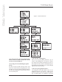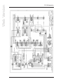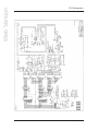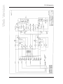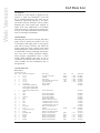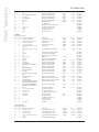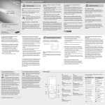
1
Web Version
Aphex Model 2020
FM Pro
Operating & Service Manual
Manufactured By
Aphex Systems Ltd.
11068 Randall St.
Sun Valley, California 91352
U. S. A.
The Model 2020 is protected under one or more of the following U. S. Patents:
5,930,374
5,898,395
5,896,458
5,848,167
5,737,432
5,612,612
5,485,077
5,483,600
5,463,695
5,450,034
5,424,488
5,422,602
5,359,665
5,334,947
5,155,769
5,115,471
4,939,471
4,843,626
4,633,501
4,578,648
Copyright 1995-2000 Aphex Systems Ltd. All rights reserved.
All Aphex product names are trademarks or registered trademarks of Aphex Systems Ltd. Other brand and
product names mentioned within the manual are trademarks of their respective owners.
Updates to this manual and other important information about the Model 2020 may be found at:
http://www.aphex.com
Model 2020 FM Pro Audio Processor
Page C-1
Web Version
FM Pro Quick Setup Guide
Notice
Following this guide will get you up and running but without much understanding of what
you are doing. We highly recommend at least a minimal study of the manual. It is written
for fast and easy reading.
Once the unit is installed, here’s the procedure to get your FM Pro operating properly
using a factory preset. You can later create
your own presets if you wish.
Step 1, Understanding The Menus. The
escape key backs you out of menus and
commitments. It continuously takes you backwards towards the Main menu. The enter key
selects menu items and makes commitments
such as save and recall. The up and down
cursers generally move the menu pointer while
the left and right cursors generally flip through
multiple menu pages.
The Spin dial acts
as an adjustment control to set menu values.
All menus branch from the Main menu. Each
menu may have one or more sub menus. The
menu tree is so logical and easy to discover
that within a few minutes you will be very
comfortable with it.
Step, Setting Up Globals. Go to the processing menu, and, by navigating through the
submenus, set up the "Global Parameters" to
match your system’s operating requirements.
The menus will state that a feature is unavailable if the associated option is not installed
in the FM Pro.
Important: Once the Globals are set, save to
the Global preset, U01, by going to the “Save
Preset” menu.
The Global Parameters
A. Processing Menu, Input/Output Menu pages 1,2,3
Input reference level
Peak output level
Unit bypass on/off
20Hz High Pass Filter on/off
16.5kHz Low Pass Filter on/off
Spectral Phase Refractor (SPR) on/off
Stereo Insert on/off
Input Source: A or D
Output: A, D, or A&D
B. Processing Menu, Pre-emphasis Limiter Menu
Pre-emphasis filter, 50 or 75 microsecond
De-emphasis on/off
C. Processing Menu, Stereo Generator Menu pages 1,2
Pilot Mix percentage
Pilot on/off
Input mode: Stereo, Mono (L, R or L+R)
Mono Mode 90% or 100%
D. Processing Menu, AES Status
Transmit rate: Slave, 32, 44.1, or 48kHz
Step 3, Select A Preset. There are
8 factory presets designed for various
programming formats. Chose one that
approximately matches your station’s
format. If you are not sure, chose “Big
Country” as a moderately aggressive
starter. If you want to really risk it,
chose “CHR” and get a very loud and
intense air sound.
Step 4, Adjust The Output Level.
While sending program audio to the
FM Pro, adjust the analog line output
(Input/Output menu) for the required
peak output level. If you are using
the PPDM multiplex option, adjust the
multiplex output level (back panel trim)
for 100% peak modulation of your
transmitter.
That’s It!
Model 2020 FM Pro Audio Processor
Page C-2
Web Version
1.0 Table of Contents
2.0 Product Description
2.1 The FM Pro Story
2.2 Description
2.3 Applications
2.4 Table of Options
2.5 Feature List
3.0 The User Interface
3.1 Metering and Status
3.1.1 Input Meter
3.1.2 Leveling Meter
3.1.3 Multiband Compressor
3.1.4 Limiter
3.1.5 Status Indicators
3.1.5.1 16.5 KHz Lowpass Filter
3.1.5.2 20Hz Highpass Filter
3.1.5.3 75 uSec Indicator
3.1.5.4 SPR
3.1.5.5- HF Limiter
3.1.5.6 Analog In
3.1.5.7 Digital In (Optional)
3.1.5.8 Data Present
3.1.5.9 DVG
3.1.5.10 Sil. Gate (Silence Gate)
3.1.5.11 Lvl. Stic. (Sticky Leveler)
3.1.6 Multiband Coupling
3.1.6.1 L><R Hard
3.1.6.2 L><R Elast. (L><R Elastic)
3.1.6.3 1><2
3.1.6.4 2><3
3.1.6.5 3><4
3.1.7 Output Status LEDs
3.1.7.1 Analog
3.1.7.2 Digital
3.1.7.3 Bypass
3.1.8 LCD Display
3.2 Front Panel Controls
3.2.1 Spin Dial
3.2.2 Navigation (Cursor) Buttons
3.2.3 Esc (No), Enter (Yes)
3.2.4 Input, Output Monitor
4.0 Navigating The Menus
4.1 Introduction To The Menu Display
4.2 Menu Display Features
4.2.1 Header
4.2.2 Menu Selections
4.2.3 Footer
4.3 Display Sleeping Mode
Model 2020 FM Pro Audio Processor
Page 1-1
Web Version
1.0 Table Of Contents
4.4 Password Security Page
4.5 Main Menu Page 1 of 2
4.5.1 Password Menu
4.5.1.1 Edit Password
4.5.1.2 View Password
4.5.1.3 Log in
4.5.1.4 Log out
4.5.2 Presets
4.5.2.1 Recall Preset
4.5.2.2 Save Preset
4.5.2.3 View list
4.5.2.4 Day Parting
4.5.2.4.1 Edit Day Parting
4.5.2.4.2 View parting
4.5.3 Processing
4.5.3.1 Processing Menu Page One
4.5.3.1.1 Input/Output Menu
4.5.3.1.2 Leveler/Gate Menu
4.5.3.1.3 Multiband Compressor Menu
4.5.3.1.4 Limiter/Bass Menu
4.5.3.2 Processing Menu Page Two
4.5.3.2.1 Preemp-Limiter Menu
4.5.3.2.2 Stereo Generator Menu
4.5.3.2.3 AES Status Menu
4.5.3.2.4 More or Less! Menu
4.5.4 Remote Link
4.6 Main Menu Page 2 of 2
4.6.1
4.6.2
4.6.3
4.6.4
Set Unit Time Menu
Display Mode Menu
Options Page
Unit Info Page
5.0 Detailed Audio Processing Description
5.1 Processing Overview
5.2 Generalized Processing Structure
5.3.1 Input Selection
5.3.2 Filters
5.3.2.1 20Hz Highpass Filter
5.3.2.2 16.5KHz Lowpass Filter
5.2.2.3 Spectral Phase Refractor (SPR)
5.3.2.4 Pre-emphasis Assist Equalizer
5.4 Frequency Discriminate Leveler (FDL)
5.5 Insert Loop
5.4.1 Silence Gate
5.4.2 Dynamic Verification Gate DVG
5.4.3 Sticky Leveling
5.4.4 Jump Ahead
5.4.5 Attenuation Lock
5.4.6 Gain Lock
5.4.7 Leveling Rate Control
5.4.8 Frequency Discrimination
Model 2020 FM Pro Audio Processor
Page 1-2
Web Version
1.0 Table Of Contents
5.6 The Multiband Compressor
5.6.1 Post Crossover Method
5.6.2 Wave Dependent Compression (WDC)
5.6.3 Peak Accelerated Compression (PAC)
5.6.4 Adjustable Crossovers (Band Filters)
5.6.5 Output Mixing
5.6.6 Adjustable Release Timing
5.6.7 Band Coupling
5.6.8 Stereo Coupling
5.6.9 The VCA Technology
5.7 Split Band Bass Processor/Limiter
5.7.1 Warm Bass Equalizer
5.7.2 Sub Bass Equalizer
5.7.3 Phase Coherent Crossover
5.7.4 Split Band Clipper (SBC)
5.8 Brightness Processor
5.9 Pre-emphasis Limiter
5.10 PPDM Stereo Generator
5.11 Digital I/O Module
6.0 Setting Up Processing
6.1 Steps In Setting Up
6.2 Targeting Processing Goals
6.3 Create the Global Preset
6.4 Select A Factory Preset
6.5 Adjusting the Processing
6.6 Leveling
6.6.1 Control Locks
6.6.2 DVG
6.6.3 Sticky Leveler
6.6.4 Silence Gate
6.6.5 Leveling Rate
6.7 Multiband Compression
6.7.1 Crossovers
6.7.2 Multiband Drive
6.7.3 Band Release
6.7.4 Band Mix
6.7.5 Band Coupling
6.8 Peak Limiting
6.9 Bass Enhancement
6.10 Brightness Enhancement
6.11 Pre-emphasis Limiting
6.12 Save Your Preset
6.13 Tutorial: A “HOW TO” Experience
7.0 All About Presets
7.1 What Are Presets?
Model 2020 FM Pro Audio Processor
Page 1-3
Web Version
1.0 Table Of Contents
7.2 What You Can Do With Presets
7.2.1 Recalling Presets
7.2.2 Saving Presets
7.2.3 Viewing Presets
7.2.4 Day-Part Scheduling
7.3 The Auto Save Feature
7.4 Do I Really Need To Create Presets?
7.5 Classes Of Presets
7.5.1 Factory Presets
7.5.2 User Presets
7.5.3 Global Preset
7.6 Tutorial--Building And Using Presets
7.7 Summary
7.6.1 Menu Navigation
7.6.2 Recalling A Preset
7.6.3 Saving A Preset (and making the global preset)
7.6.4 Day Parting (F4)
8.0 Password Security System
8.1 Why A Security System?
8.2 Log-in Access
8.3 Logging Out
8.4 Auto Save
8.3.1 Manual Log Out
8.3.2 Auto Lock Out
8.5 Password Enabling
8.5.1 Software Password Enabling
8.5.2 Hardware Password Enabling
8.6 Access With Lost Password
8.6.1 Clearing The Password Memory
8.7 Setting The Password
8.8 Clearing The Password
9.0 Using Digital Audio
9.1 Connecting AES/EBU Lines
9.1.1 Cable Pinout
9.2 AES/EBU Synchronization
9.3 Digital-To-Analog Conversion
9.4 Auto Source
9.5 Digital Output
9.6 Facts About Digital Audio, Bit Rate Reduction and Dynamics Processing
10.0 Using Multiplex
10.1 Stereo Generator Option
10.2 The Stereo Generator Menus
Model 2020 FM Pro Audio Processor
Page 1-4
Web Version
1.0 Table Of Contents
10.3 Presets Memory
10.4 Mode Settings
10.4.1 Mono Modes
10.4.2 Stereo Mode
10.5 Pilot Function
10.6 Multiplex Output
10.7 Multiplex Cable Connections
10.8 Modulation Overshoot Problems
10.8.1 STL Problems
10.8.2 FM Exciter Problems
10.8.3 Composite Clippers
10.9 Using RDS Encoders
11. Remote Operation
11.1 Hardware Requirements
11.2 Software Installation
11.3 Cable Wiring
11.3.1 Direct Connection
11.3.2 Modem Connections
11.3.2.1 Modem To FM Pro
11.3.2.2 PC To Modem
11.4 Operation By Modem
11.4.1 Usable Modem Types
11.4.2 Modem In The Windows Operating System
11.4.3 Modem Installation Procedure
11.4.4 Troubleshooting The Modem
11.4.5 Compatibility Issues
11.5 The PC Remote Control Main Form
11.5.1 Link Status
11.5.2 Transmit Speed
11.5.3 Receive Speed
11.6 Port Direct Linking
11.6.1 A Note On Day Parting
11.7 Modem Linking
11.8 Using The Remote Control Panel
11.9 Dealing With Presets
11.9.1 Recall Preset
11.9.2 Save Preset
11.10 The View Menu
12. Product Specifications
12.1 Getting Meaningful Numbers
12.2 FM Pro Setup
12.3 Test Equipment Connections
12.4 The Specifications
12.4.1 General Analog
12.4.2 Analog Input
Model 2020 FM Pro Audio Processor
Page 1-5
Web Version
1.0 Table Of Contents
12.4.3 Analog Line Outputs
12.4.4 Digital Inlut
12.4.5 Digital Output
12.4.6 Composite Baseband Output
12.4.7 Remote Control Interface
12.4.9 Physical
12.4.10 Environmental
13. Test & Calibration
14. Installation Instructions
14.1 Unpacking
14.2 Damage & Claims
14.3 Mains Voltage and Fuses
14.4 Power Cord
14.6 Mounting In A Rack
14.6 Proper Ventillation
14.7 Safety Considerations
14.8 Analog Balanced I/O
14.8.1 Standard Wiring
14.8.2 Main Input Wiring
14.8.3 Main Output Wiring
14.8.4 Insert Loop I/O Connections
14.9 Digital Audio I/O
14.10 Multiplex Output
14.11 RS-232 Connector
14.12 Summary
15. Schematics
16. Parts List
17. Service & Warranty Information
17.1 Obtaining Service For The FM Pro
17.2 Warranty Claims
17.3 What Is Covered
18. Web Broadcasting Applications
18.1 Why Process the Audio?
18.2 Basics of Processing
18.2.1 Leveling
18.2.2 Peak Limiting
18.2.3 Designing the Sound
18.3 Getting the Best Processing
Model 2020 FM Pro Audio Processor
Page 1-6
Web Version
1.0 Table Of Contents
18.4 Digital Versus Analog Processing
18.5 How to Use the Model 2020
18.5.1 Set the Input Level
18.5.2 Set the Output Level
18.5.3 Set Up the Processing
18.6 Bit Rate Effects
Model 2020 FM Pro Audio Processor
Page 1-7
Web Version
2.0 Product Description
2.1 The FM Pro Story
Aphex entered the world of broadcast audio processing with the Type II Aural Exciter in 1981.
Since then Aphex has continued developing leading broadcast audio products. The Compellor
became and remains the world standard automatic
level controller. The Dominator became the world
standard multiband peak limiter. The Digicoder,
the only patented stereo generator technology, took
its place as the world’s best stereo generator.
Together the Compellor, Dominator, Aural Exciter,
and Digicoder comprise the Aphex Audiophile Air
Chain which has gained worldwide recognition
as the premiere FM audio processing system for
transparent, lifelike transmission of sound. Worldwide, many leading broadcast institutions have
adopted these Aphex products as their technical
standard and continue to employ them exclusively
in high grade radio and television network systems.
As proud as we are of the Audiophile Air Chain
and what it achieves in its sonic purity, we realize
many broadcast applications demand something
else. For example, a need exists to literally design
the sound of a radio station, i.e., to generate a
unique and competitive air sound intentionally
modified in certain ways. Also, the processor
may be required to operate directly within a
digital audio path. Furthermore, there is a demand
for programmability, remote control, and day-part
automation. We developed the FM Pro to fulfill
all these needs and more. Naturally, we borrowed
upon many of the proven and exclusive Aphex
patented circuits to achieve a technically excellent
design, but while we were at it we invented at least
six additional new and innovative audio processing concepts giving the FM Pro truly advanced
capabilities and performance.
2.2 Description
The FM Pro is not just a boxed-up combination
of prior Aphex products. It is a totally new
and advanced audio processing system tailored
especially to the demands of FM broadcasting.
Competition ready, the FM Pro is completely
adjustable from detailed and neutral to heavy and
loud. Thanks to the numerous design innovations,
even at extreme settings exceptional audio quality
is maintained. Unlike the competing digital or
analog audio processors which afford relatively
little flexibility, the FM Pro is a virtually sound
Model 2020 FM Pro Audio Processor
designer’s palette allowing you to paint a truly
unique and competitive on-air sound. Don’t be
misled, however, the FM Pro can just as well be set
up to sound as neutral and transparent as desired.
Modular design makes the FM Pro space-saving
and cost efficient compared to other processors.
Plug-in options are easily field installed and can
be shipped to specification. Sixteen recallable user
presets are provided for manual selection or daypart automation. For convenience, eight factory
presets covering a variety of formats are built-in
to get you up and running quickly.
Day-part
automation is completely self-contained and driven
by an accurate internal clock/calendar timer. Front
panel operation is made easy and intuitive through
the logical menu tree. An RS232 port permits
remote control and monitoring of the FM Pro from
almost any location through the use of a standard
personal computer and a serial cable or modem.
A simple but effective supervised password system
can be engaged to maintain security over the FM
Pro’s operation. Fail-safe operation is assured
by a power-off internal relay bypass of both the
analog and digital audio I/O circuits. Power-up fast
recovery gets the FM Pro back on line with all
programmable parameters set correctly and operating in just a few tenths of a second. The front panel
displays are more than token indicators. They
indicate the actual operation of all major process
functions in real time.
2.3 Applications
The flexibility of the Aphex FM Pro makes it
suitable for nearly every FM broadcasting entity
from government owned to purely commercial.
Whether your audio system contains analog, digital
or both formats, the FM Pro can be configured to fit
in perfectly. Fully adjustable parameters allow you
to optimize the FM Pro for any program format:
classical music, talk, even heavy metal. Automated
transformation of processing parameters by the day,
hour, and minute allow radio stations with varying
formats to tailor the FM Pro exactly as required for
each day-part. Although the FM Pro is intended
mainly for FM broadcasting, it will find many
interesting applications in other fields where absolute audio control and flexible sound tailoring are
desired. Digital and analog mastering, recording,
satellite uplinks, and amplified sound are just a
few examples.
Page 2-1
Web Version
2.0 Product Description
2.4 FM Pro OPTIONS
Analog
Stereo
Input
Analog
Stereo
Output
Basic
X
X
Option 1
X
X
Option 2
X
X
X
Option 3
X
X
X
AES/EBU
I/O
Pre-Emp
Limiter
PPDM
MPX
Output
X
X
2.5 FUNCTIONS AND FEATURES
1. Analog and Digital Stereo Inputs
2. Input processing functions
a. 20Hz Highpass Filter
b. 16.5KHz lowpass filter
c. SPR process
d. Selectable external processing loop patch
3. Frequency Discriminate Leveler
a. Improved parametric controls
b. New “sticky” leveling feature
c. Selectable patented “DVG”
d. Selectable silence gate
e. Adjustable silence gate threshold
f. Adjustable AGC upper and lower control limits
4. Multiband compressor
a. 4-bands
b. adjustable crossover frequencies
c. Easyrider compression
d. “Peak Accelerated Compression” (PAC) algorithm
e. Band-by-band stereo elastic coupling
f. Band-to-band forward elastic coupling
g. Adjustable compression drive
h. Separate adjustable release time per band
i. Selectable stereo hard coupling
j. Compression drive control
k. Output band mixing facility
l. New “post crossover” multiband technique
m. High or Low selectable ratio
5. Bass Processor
a. Distortion canceled bass clipper
b. “Warm bass” equalizer
c. “Sub Bass” equalizer
d. Total “Bass Mix” control
6. Peak Limiter
a. Bass interactive to reduce intermod distortion
b. Instant processing, i.e., no pumping
c. Zero overshoot
d. Master drive control configures loudness factors
7. Optional pre-emphasis processor
a. Special 50 or 75 microsecond pre-emphasis filter
b. Digicoder type pre-emphasis limiter
c. Digicoder type non-overshoot final lowpass filters
d. Output ready for any stereo generator
8. Optional digital I/O module
a. AES/EBU format up to 20 bits
b. Selectable output sample rate: 32K, 44.1K, 48K
c. Auto “lock on” for input rates of 32K, 44.1K or 48K
d. Input and output sample rates separately selectable
Model 2020 FM Pro Audio Processor
9. Optional Digicoder stereo generator module
a. Digicoder type PPDM stereo generator
b. Analog multiplex output
c. stereo/mono mode switching
d. Pilot on/off
e. trimmable multiplex output level
10. Digital remote control
a. RS232 digital interface
b. Windows 3.1 or 95 virtual control panel software
c. Complete operating capabilities
d. Complete visual real time meter displays
e. Password security options
11. Front panel user interface
a. LCD graphics panel display
b. Password security features
c. Rotary encoder knob
d. Up/Down, L/R cursor buttons
e. Menu selection system
f. Real time LED bargraph meters for:
1. Leveling
2. 4-band compression
3. Limiting
4. Stereo input VU
g. Real time LED indicators for:
1. 16.5KHz Lowpass
2. 20Hz Highpass
3. 50/75uS Pre-emphasis
4. SPR
5. Analog In selected
6. Digital in selected
7. Digital data presence
8. DVG
9. Sticky on/off
10. Silence gate
11. L><R hard couple
12. L><R elastic couple
13. 1><2 couple
14. 2><3 couple
15. 3><4 couple
16. Analog output presence
17. Digital output presence
18. Bypass on/off
h.
Headphone monitor selector
1. Monitor input signal & volume
2. Monitor output signal & volume
Page 2-2
Web Version
3.0 The User Interface
Figure 3-1 illustrates the front panel features of the
FM Pro. You may refer to that diagram for a quick
summary of all available controls and indicators.
The following description, taken in conjunction
with the diagram, will give you a very good
understanding of all the features and controls, their
purpose and use.
3.1 Metering and Status
While other processors provide only drab, jittery,
and inaccurate LCD meter displays and tell the
status of structural functions only on buried menu
pages, the FM Pro provides the user with colorful
front panel metering that is true and easy to read.
The major dynamic processes are metered by realtime LED bar graph displays while the on/off
status of static functions are indicated by single
LED’s. The state of all major functions of the FM
Pro can therefore be observed at any time with one
one glance at the front panel.
Following is a more detailed description of all the
panel indicators.
3.1.1 Input Meter
Two yellow 10-segment bargraph meters are provided to indicate the stereo audio input level relative to the current input reference setting. The scale
indicates from -18dB to +9dB in 3dB steps.
Note: The input reference level is adjusted in the
Processing I/O menu. Left and Right inputs are
adjusted in tandem with one control in software.
For analog inputs, set the input reference level
to cause a program reference tone to read
zero VU. The digital audio input automatically
sets the 0VU reference to 10dB below digital
maximum peak reference.
3.1.2 Leveling Meter
This red dot-mode 10-segment meter indicates the
amount of automatic gain correction that is created
by the leveler. The leveler gain control is applied
equally to both audio channels. The scale indicates
up to 15 dB of gain addition, and 7.5 dB of gain
reduction. The amount of activity that is seen in
this meter will vary widely depending on program
material and the settings of the leveler/gate parameters.
Note: Control for the Leveling function is located in the Processing, Leveler/Gate section of the
control menu.
Model 2020 FM Pro Audio Processor
3.1.3 Multiband Compressor
Four green 10-segment bargraph meters labeled
“Low”, ”Mid 1”, “Mid 2”, and “High” indicate
the amount of gain reduction taking place in each
of the four compression frequency bands up to a
maximum of 15dB. Since the multiband compressor is a two-channel process, 8 meters would ordinarily be required to display all bands. For convenience, however, the front panel meters merge
the dual channel indications into one set of four
displays. Each band meter displays the greater
amount of gain reduction of the left and right
channel at all times.
Note: All multiband compression parameters are
controlled in the control menu under Processing,
Multiband.
3.1.4 Limiter
The Limiting meter is a red dot-mode 10-segment
display that indicates the amount of peak limiting
occurring in the limiter/bass processor circuit after
the multiband compression. This is separate from
and does not display any pre-emphasis limiting that
takes place when the pre-emphasis limiter option
is used. The scale is from 1 dB of limiting to 10
dB of limiting in 1 dB steps.
Note: Limiter parameters are controlled in the
users menu under Processing, Limiter/bass.
3.1.5 Status Indicators
Individual LED’s indicate the status of principal
processing functions other than functions indicated
by the 8 bar graph meters. A more detailed description of these functions follows.
3.1.5.1 16.5 KHz Lowpass Filter
This is a member of the input pre-processing group
of filters. You can invoke this filter to clean up
unwanted high frequency noise which may have
resulted from interference in the STL path, or other
source. It is not related to the 15KHz lowpass
filters associated with the stereo generator. This
filter works on both the analog and digital audio
inputs.
Note: Control of the 16.5KHz Lowpass Filter is
located in Processing, Input/Output menu.
3.1.5.2 20Hz Highpass Filter
This is another member of the input pre-processing
Page 3-1
Web Version
3.0 The User Interface
group of filters. You can invoke this filter to clean
up unwanted rumble or subsonic noise which may
be encountered. It is not related to the 15KHz
lowpass filters associated with the stereo generator.
This filter works on both the analog and digital
audio inputs.
Note: Control of the 20Hz Highpass Filter is
located in the Processing, Input/output menu.
3.1.5.3 75 uSec Indicator
This light tells if the pre-emphasis option is set
to 75 microseconds. It remains dark if the preemphasis is set to 50 microseconds or if the preemphasis limiter option is not installed.
Note: This light responds to the pre-emphasis
selection chosen in the Processing, Pre-emp
Limiter menu.
3.1.5.4 SPR
Spectral Phase Refractor(SPR) is another member
of the input pre-processing group of filters. The
SPR filter contains a flat frequency response but
introduces a frequency dependent phase rotation
into the audio path for the purpose of increasing
the subjective clarity of the audio. A further effect
of SPR is to improve voice waveform symmetry as
an aid to the limiter. This filter works on both the
analog and digital audio inputs.
3.1.5 Digital In (Optional)
Indicates if the audio input is set to digital (versus
analog). Digital input is part of the digital audio
option and is available only when the option
is installed. If the digital audio option is not
installed, this light stays dark and the Analog In
light remains lit.
Note: Selection of the analog or digital input is
located in the Processing, Input/Output menu.
Part of the digital audio option is the “Auto
Source” feature that will automatically switch from
the digital input to the analog input if excessive
errors are detected at the digital audio input. In
such a case, the Analog In and Digital In lights
will indicate which input has been automatically
selected.
Note: Enable/disable of the Auto Source feature
is located in the Processing, AES Status menu.
3.1.5.8 Data Present
Note: Control of the SPR filter is located in the
Processing, Input/Output menu.
When the digital audio option is installed, this
LED shows if there is AES/EBU data arriving at
the digital audio input to the FM Pro. If there
are errors present in the AES/EBU datastream,
the Data Present light will flash, and as stated
above, when the Auto Source feature is selected,
the unit will automatically switch to the analog
audio inputs. As the datastream error condition
rectifies itself, the FM Pro will automatically
switch back to the Digital input.
3.1.5.5- HF Limiter
3.1.5.9 DVG
This is another name for the Pre-emphasis Limiter,
which is an optional processing module. The light
is continuously dark if the option is not installed.
If the option is installed, then the LED indicates
whether the Pre-emphasis Limiter is switched on
or off.
Note: Control of the HF Limiter is located in the
Processing, Pre-emp Limiter menu.
3.1.5.6 Analog In
This LED lights if the audio input is set to analog
(versus digital).
Note: Selection of analog or digital input is
located in the Processing, Input/Output menu.
Model 2020 FM Pro Audio Processor
If the Dynamic Verification Gate (DVG) is turned
on, this LED flashes in response to the DVG
action. If the DVG is switched off, the LED
remains dark. Dynamic Verification Gate is an
Aphex patented invention that allows the leveler’s
gain correction to move only during the brief
periods when present peaks are above the historical
average peak level. Based on the pattern of the
audio waveform, the DVG will freeze the movement of gain during intervals when the ear is
most cognizant of the gain movement, thus making
the leveler more transparent sounding. The DVG
also serves to freeze the leveler gain during brief
program pauses of about 1.5 seconds or less duration, preventing immediate noise swelling. After
about 1.5 seconds, the DVG releases control. The
DVG works only with the leveler function of
the FM Pro, and does not affect the compression
Page 3-2
Web Version
3.0 The User Interface
system in any way.
Note: Enable/disable of the DVG feature is
located in the Processing, Leveler menu.
3.1.5.10 Sil. Gate (Silence Gate)
The Silence Gate LED lights up whenever the
Silence Gate activates. The Silence Gate is a
delayed level detector which acts to freeze the
leveler gain during extended pauses in program.
Since the DVG serves this purpose for brief program pauses, the Silence Gate is delayed about
1 second to take over from the DVG for more
lengthy periods. The delayed response prevents the
Silence Gate from constantly interfering with the
action of the Leveler, deferring gain gate control to
the DVG between periods of silence.
Note: Enable/disable and Threshold of the
Silence Gate feature is located in the Processing,
Leveler menu.
3.1.5.11 Lvl. Stic. (Sticky Leveler)
The Lvl. Stic. LED lights up when the user selectable Sticky Leveler is turned on. The Sticky
leveller is a new Aphex invention that keeps
the leveler’s gain frozen until the input signal
amplitude changes by more than a certain amount.
By holding constant gain until the audio level
exceeds a user selectable window, the Sticky
Leveler further improves the transparency of the
leveler’s action, especially at the faster rate settings.
Note: Controls for the Sticky leveler are located
in the processing Leveler/Gate menu.
3.1.5.12 Insert
The Insert LED lights up when the processing
“insert loop” is turned on. This control allows
the user to insert any type of stereo audio processor between the Leveler and the Multiband
Compressor. The insert inputs and outputs are
supplied by rear panel unbalanced (pin 2 hot, 1&3
grounded) XLR connectors.
Note: On/Off control for the Insert Loop is
located in the Processing, Input/Output menu.
3.1.6 Multiband Coupling
Five LED’s are provided to show the current status
of the Multiband Compressor coupling features.
The L><R coupling features refer to the stereo
Model 2020 FM Pro Audio Processor
coupling of the Multiband Compressor bands. The
band><band features refer to coupling between
adjacent bands of the same channel. When turned
on, the band><band coupling is enacted in both
channels at once. The band><band coupling does
not produce any stereo coupling effect. Both
band><band and L><R coupling may be enacted
simultaneously.
Note: Multiband coupling features are controlled in the Processing, Multiband menu.
3.1.6.1 L><R Hard
Couples the compression gain of left and right
compressors directly, i.e., whichever channel produces greater gain reduction controls the gain
of both channels equally and at the same attack/
release rates.
3.1.6.2 L><R Elast. (L><R Elastic)
Couples the compression gain of left and right
compressors elastically, i.e., whichever channel
produces greater gain reduction influences the
the gain of the opposite channel through a slow
averaging effect.
3.1.6.3 1><2
Couples the gain control of band 1 to the gain
control of band 2 in such a way that whichever
band produces the greater amount of gain reduction
influences the the gain of the other band through a
slow averaging effect.
3.1.6.4 2><3
Couples the gain control of band 2 to the gain
control of band 3 in such a way that whichever
band produces the greater amount of gain reduction
influences the the gain of the other band through a
slow averaging effect.
3.1.6.5 3><4
Couples the gain control of band 3 to the gain
control of band 4 in such a way that whichever
band produces the greater amount of gain reduction
influences the the gain of the other band through a
slow averaging effect.
3.1.7 Output Status LEDs
Three LED’s are provided to show the processor
output status, analog, digital, or bypass.
Page 3-3
Web Version
3.0 The User Interface
Note: The output controls are located in the
Processing, Input/Output menu.
3.1.7.1 Analog
Indicates if the analog output is turned on. The
analog output is permanently selected unless the
digital audio option is installed in which case the
user can select analog out, digital out, or both at
once.
3.1.7.2 Digital
When the digital audio option is installed, this light
indicates if the digital output is turned on.
3.1.7.3 Bypass
In bypass mode, the analog input jacks are relay
connected directly to the analog output jacks, and
the AES/EBU input jacks are relay connected
directly to the AES/EBU output jacks. The bypass
mode can be user selected and automatically occurs
when the power is off.
cursors move the pointer up and down through
selections on a menu page, while the left and
right cursors switch between multiple pages of a
multipage menu.
3.2.3 Esc (No), Enter (Yes)
These two lighted red buttons allow the user to
commit to or escape from menu choices. Repeated
escapes will back out of menus until the Main menu
is reached. Enter (yes) is used to select a menu
choice or verify a menu commitment.
3.2.4 Input, Output Monitor
The lighted red buttons above the headphone jack
select their respective audio signals for monitoring.
The selected signal appears at the stereo headphone
jack only. The proper de-emphasis (if appropriate)
is automatically inserted in the output monitor. The
input monitor taps the unaltered input signal.
Note: The volume of the input and output signals
can be set independently in the Processing,
input/Output menu.
3.1.8 LCD Display
All operating menus and messages will appear on
this LCD display. Refer to section 4, “Navigating
The Menus” for detailed information on using the
menu system.
end
3.2 Front Panel Controls
The Fm Pro utilizes a sophisticated yet intuitive
method of user interface. The right side of the
front panel comprises the user controls. By means
of LCD menus, the navigation/control keys, and
the “Spin” dial, all processor controls are easily
accessed. The right half of the panel also contains
a high quality headphone monitor that provides
a means for listening to the raw input signal in
comparison to the fully processed output signal.
3.2.1 Spin Dial
The Spin dial is used to adjust the variable menu
parameters which have been chosen by use of the
navigation keys. Depending upon the situation, the
Spin dial will act like a potentiometer or selector
switch.
3.2.2 Navigation (Cursor) Buttons
The four lighted red buttons that are labeled with
white arrows pointing up, down, right, and left are
used to navigate the various pages and menus seen
on the LCD display. Generally, the up and down
Model 2020 FM Pro Audio Processor
Page 3-4
Web Version
4.0 Navigating The Menus
The flow chart of Figure 4-1 illustrates the entire
menu tree of the FM Pro. You may find referring
to the chart helpful while reading this section of
the manual.
4.1 Introduction To The Menu Display
The Liquid Crystal Display (LCD) menu system
of the FM Pro is designed to be logical and easy
to understand. Without any instruction at all you
would probably be able to find your way around
and control the unit through your own exploration.
Note: The various menus all branch from the
Main Menu. You gain access to the Main Menu
by first passing through the password security
check, if it is activated. Refer to section 8,
“Password Security System” for information
about enabling and disabling the password
requirement.
The LCD display has a number of features that
give the user an indication of the present location
within the menu, the time of day, the current
on-air preset, and any parameter being adjusted.
Following is a detailed description of the various
menu features.
4.2 Menu Display Features
you are in a functional control menu such as the
“PROCESSING” menu, then you will see up to
four function options labeled F1, F2, F3, F4 per
page. Each page of a multiple page menu will
continue from the previous page such as F5, F6,
F7, F8 etc.
If you are in other menus such as the PRESETS,
and DAY PARTING menus, the logic of selection
labeling is similar, except the selections may be
labeled as U01, U02..., or S1, S2..., etc. The
selections flow from page to page as necessary to
accommodate all available selections in a given
menu.
4.2.3 Footer
The bottom line reads out a short phrase indicating
what is expected as input. It may be “Enter key”,
“Enter value”, “Enter function”, etc. The bottom
right corner contains an alternating display that
toggles between the time of day and the memory
preset number (U01, P01, etc.) that is currently
on-air.
4.3 Display Sleeping Mode
The menu system sleeps when not in use by a
logged in user. During this time, the “Welcome
to Aphex” logo screen is displayed. This screen
displays the current time and software version.
How To Make Selections
1. To MOVE BETWEEN PAGES of multiple page menus, use the left and right arrow keys.
2. To MOVE THE POINTER, use the up and down arrow keys.
3. To SELECT THE FUNCTION, press the Enter (YES) button.
4. To ESCAPE FROM A SELECTION, press the Esc. (NO) key.
4.2.1 Header
The top line left side of the display shows the current menu name while the current page is indicated
on the right. For example, the top line may read:
[MAIN MENU
P:1.2]. This indicates you
are in the Main Menu, page 1 of 2 pages. Once
past the Main Menu, the menu name always refers
to the functional area you are controlling. For
example, the Leveler menus are named, simply,
“LEVELER”.
4.2.2 Menu Selections
Displayed below the header are the messages or
selection options as provided by various menus. If
Model 2020 FM Pro Audio Processor
Pressing any key wakes up the menu system and
clears the logo screen, bringing up the Password
Security page.
4.4 Password Security Page
This page is the pathway to the Main Menu if a
password is required. Pressing any key when the
logo screen is displayed brings you to this page.
If no password is currently active in the security
system, this page will be omitted and the screen
will go to the LOG IN VERIFY page, telling you
a password is not required. You can then press the
enter key and pass directly to the Main Menu.
Page 4-1
Web Version
4.0 Navigating The Menus
Note: For more information on the password
and security system see section 8 of this manual.
4.5 Main Menu Page 1 of 2
The Main Menu consists of two pages containing
8 selections, F1 through F8, that lead you to all
other menus. Selecting F1 through F8 opens
the associated menu by pressing enter. The first
page contains these selections which are described
below:
[MAIN MENU P:1.2]
F1- Password
F2- Presets
F3- Processing
F4- Remote Link
4.5.1 Password Menu
This section contains all password security elements including logging in and out as a user, as
well as password maintenance. The four menu
selections available are as follows.
[PASSWORD MENU]
F1 - Edit password
F2 - View password
F3 - Log In
F4 - Log Out
4.5.1.1 Edit Password
This page allows you to overwrite the password
with a new one or to delete the password all
together. Do so by moving the cursor and selecting
a character from the character table. Use the spin
dial to select characters from the table, and press
Enter to place the character at the cursor position.
The cursor will automatically advance one more
space. Repeat the process until your new password
is all entered. You can use the space in the character table to put a blank space in the password.
For example, you could have a password like
“kitty cat”. To delete the password, simply enter
all blank spaces over the old password. When the
password is ready to save, use the cursor key to
highlight the word “Save” and press Enter.
Note: Do not use the Enter key to advance
to the word “Save”. You will inadvertently
press Enter over “Clr” and erase your new
password. Use only the left and right arrow
keys to advance the cursor to “Save”.
Model 2020 FM Pro Audio Processor
When you press Enter at the “Save” position, you
will be passed to the View Password page and
asked to verify that you want this new password
to be entered into memory. Press Enter to take the
new password or Esc. to revert back to the Edit
Password page. Pressing Esc. again will revert you
back to the Password Menu, and pressing Esc.
once again will revert you all the way back to
the Main Menu.
4.5.1.2 View Password
To observe (without the option of editing) the
current password, select F2 “View Password” from
the Password Menu. Press Esc. to return to the
Password Menu.
4.5.1.3 Log in
In the software version provided at the time of this
writing, this is a rather unnecessary menu option
since you can’t get to this option unless you are
already logged in. It is being reserved for a future
software version which may include and expanded
password security system.
Selecting this option brings you to a page similar
to the Edit Password page. In this case, you enter
the required password and upon selecting “Save”
you get a validation screen which tells you if your
password matches or is in error.
4.5.1.4 Log out
From the Password Menu, select F4-Log Out and
press Enter. The “Welcome to Aphex” logo screen
will pop up. If a password is in effect, the FM pro
is now in a secure mode safe from tampering by
unauthorized personnel.
4.5.2 Presets
From the Main Menu, select F2-Presets and press
Enter to go to the Presets Menu. From here you can
recall processing presets, save current processing
parameters to user presets, view the list of presets,
or manage day parting functions. The selections
available are:
[PRESETS MENU]
F1 - Recall Preset
F2 - Save Preset
F3 - View list
F4 - Day Parting
Page 4-2
Web Version
4.0 Navigating The Menus
4.5.2.1 Recall Preset
Six pages of presets will be displayed. From here
you can instantly put any available preset on the air.
To do so, move to the page containing the desired
preset and move the pointer to the preset you want.
Press Enter and the preset will be transferred to
the FM Pro’s processing parameters. The transfer
occurs softly so you won’t hear any “pops” as the
parameters change. There are two pages of factory
presets labeled P01 through P08, and four pages
of user presets labeled U01 through U16. Refer
to section 7 of this manual for information about
building and using presets.
4.5.2.2 Save Preset
From this menu you can save the processor settings
currently running in the FM Pro to any user preset
memory. All six pages of presets are made available just as in the Recall Preset menu. You will
be informed that you can’t save to a factory preset
location if you attempt to do so. To save to a
user preset, move to the page containing the preset
memory you want, and move the pointer to the
correct location on the page. Press Enter to send
the current processing parameters to that preset.
You will be asked to overwrite the old preset,
even if it was not yet used. You press (YES) and
the ENTER NAME page will appear. This page
operates exactly as the Edit Password page. Select
a character from the character table using the
spin dial and press Enter to place the character at
the cursor position. The cursor will automatically
advance one more space. Repeat the process until
your complete preset name is entered. You can use
the space in the character table to put a blank
space in the name. For example, you could have a
preset name like “hot beat”, or “test 1”. When the
preset name is ready to save, use the cursor key to
highlight the word “Save” and press Enter.
Note: Do not use the Enter key to advance to
the word “Save”. You will inadvertently press
Enter over “Clr” and erase your new preset
name. Use only the left and right arrow keys to
advance the cursor to “Save”.
You will be shown the NEW PRESET page and
asked to verify the new name. Press (YES) and
the new preset is stored. Press (NO) and you will
be jetted back to the SAVE PRESET screen from
which you came.
4.5.2.3 View list
The View list function is provided to allow the user
Model 2020 FM Pro Audio Processor
to see the name and date of origin of any of the
presets in the Fm Pro. All six pages of presets are
available to view, and can be accessed by pressing
the left and right arrow buttons. Once a preset is
selected, the VIEW PRESET DETAIL page will
appear showing the preset name and date saved.
4.5.2.4 Day Parting
In the Parting Menu you can view and edit day
parting schedules, and you can turn parting on or
off. To turn day parting on or off, position the
pointer to the “Parting status” line and turn the
Spin dial to select on and off. Viewing and editing
functions are performed as follows.
4.5.2.4.1 Edit Day Parting
The Edit Parting menu allows you to select “Daily
Edit” or “Weekly Edit”. If you chose “Daily Edit”
you will be taken to the “Parting Sets” menu where
you will be able to chose among 8 day-part sets
to edit. If you chose “Weekly Edit”, you will be
taken to the weekday scheduler page. Please refer
to section 7 of this manual for detailed information
about setting up a day parting schedule.
4.5.2.4.2 View parting
The View Parting menu allows you to select “Daily
Events” or “Weekly Events”. If you chose “Daily
Events” you will be taken to the “Parting Sets”
menu from which you may select among 8 daypart sets to view. If you select “Weekly Events”
you will be taken to the “View Weekly Set” menu
to view the weekday schedule.
4.5.3 Processing
The “Processing” selection on page 1 of the Main
Menu launches you to the two-page “Processing
Menu” from which you can access all the audio
processing controls. In all, submenus for 8 major
processing functions, F1 through F8, are available
from this menu. These submenus cover the entire
processing structure of the FM Pro.
4.5.3.1 Processing Menu Page One
The first 4 of the 8 function submenus are accessed
from page one. They are:
[PROCESSING P:1.2]
F1 - Input/Output
F2 - Leveler/Gate
F3 - Multiband Compressor
F4 - Limiter/Bass
Page 4-3
Web Version
4.0 Navigating The Menus
Note: Refer to the appropriate sections of this
manual for a detailed description of the processing parameters and how to set them up.
4.5.3.1.1 Input/Output Menu
This menu contains 3 pages. Page one gives control
over the input and output levels, and the hardwire
I/O bypass. Page two gives control over the three
input processing filters and the stereo insert loop.
Page three gives control over the input and
output source selection and the headphone monitor
volume. Use the up and down arrow keys to select a
function and use the Spin dial to set the value.
4.5.3.1.2 Leveler/Gate Menu
This menu has three pages. Page one gives control
over the leveling rate, the maximum gain and
maximum attenuation settings. Page two gives
control over the DVG and the Sticky Leveler function. Page three gives control over the Silence
Gate function. Use the up and down arrow keys
to select a function and use the Spin dial to set
the value.
4.5.3.1.3 Multiband Compressor Menu
The Multiband Compressor menu has a total of five
pages; the first of which allows the user to set
the crossover frequencies for the 4 band compressor. To adjust crossovers, set the pointer to the
desired crossover and use the Spin dial to set the
frequency.
Page two lets you set the multiband compression
drive. Simply use the Spin dial to set the value.
Page three gives control over the release times of
each of the four bands of the compressor. To adjust
release times, place the pointer adjacent to the band
you want to adjust, then use the Spin dial to set
the value.
Page four allows you to adjust the output mix of
the multiband compressor. At this point you can
make equalization adjustments to the audio based
upon the band crossover frequencies. To make an
adjustment, place the pointer next to the band you
want to adjust, then use the Spin dial to set the
value.
The final page gives control over stereo coupling
and band-to-band linking. As with the other pages,
place the pointer next to the selection and use the
Spin dial to set the value.
Model 2020 FM Pro Audio Processor
4.5.3.1.4 Limiter/Bass Menu
This menu has two pages. Page one gives control
over the master limiter drive, the bass drive, and
the brightness enhancer. Page two gives control
over the warm bass and sub bass equalizers. To
adjust drive or equalization, set the pointer to the
desired function and use the Spin dial to set the
value.
4.5.3.2 Processing Menu Page Two
The second 4 of the 8 function submenus are
accessed from page two. They are:
[PROCESSING P:2.2]
F5 - Preemp.-Limiter
F6 - Stereo Gen.
F7 - AES status
F8 - More or Less!
Note: Refer to the appropriate sections of this
manual for a detailed description of the processing parameters and how to set them up.
4.5.3.2.1 Preemp-Limiter Menu
If the Pre-emphasis Limiter option is not installed
in the FM Pro, then this menu will not be available.
If the option is installed, a single page gives control
over the limiter on/off, the limiter hardness, and the
pre-emphasis/de-emphasis options. To adjust these
parameters, place the pointer adjacent to the item
then use the Spin dial to set the value.
4.5.3.2.2 Stereo Generator Menu
If the PPDM Stereo Generator option is not installed
in the FM Pro, then this menu will not be available.
If the option is installed, two pages give control
over the stereo generator functions. Page one gives
control over the pilot signal on/off and injection.
Page two gives control over the mono/stereo modes
and the mono modulation reference of 90% or
100%. To adjust these parameters, place the pointer
adjacent to the item then use the Spin dial to set
the value.
4.5.3.2.3 AES Status Menu
Digital input and outputs are available as an option
in the FM Pro. If this option is not installed, the
AES Status menu will not be available. If the option
is installed, then a single page gives control over
the output sample rate and the auto switch feature.
The input data rate and error condition are also
reported on this screen. To adjust parameters, place
Page 4-4
Web Version
4.0 Navigating The Menus
the pointer adjacent to the item then use the Spin
dial to set the value.
4.5.3.2.4 More or Less! Menu
For a quick adjustment of the on-air loudness, enter
the More or Less! menu and use the Spin dial
to increase or decrease the FM Pro’s processing
density. This control simultaneously adjusts a
number of parameters in the processor, and, when
any processing limit is reached, the More or Less
control stops any further adjustments.
this menu.
4.6.4 Unit Info Page
This page displays the version and date of the
software installed in the FM Pro. The telephone
number for Aphex Systems customer support is
also displayed. Nice touch, right?
4.5.4 Remote Link
The FM Pro has remote control capabilities via
factory provided software. From the Remote Link
menu, the user has the ability to turn the remote
link on or off, specify the type of connection: either
modem or RS-232 direct, and observe the status
of the remote link.
4.6 Main Menu Page 2 of 2
As previously stated, the Main Menu consists of
two pages containing 8 selections, F1 through F8,
that lead you to all other menus. Selecting F1
through F8 opens the associated menu by pressing
enter. The second page of the Main Menu contains
these selections which are described below:
[MAIN MENU P:2.2]
F5 - Set time
F6 - Display mode
F7 - Unit options
F8 - Unit Info
4.6.1 Set Unit Time Menu
Upon entering this menu, the FM Pro’s internal
clock and calendar will be displayed. You can set
both the clock and calendar from this page. To
change settings, use all four arrow keys to place
the pointer next to the item and use the Spin dial
to set the value.
4.6.2 Display Mode Menu
This menu controls the Lock Out time and the
Auto Save feature. To set these items, place the
pointer next to the item and use the Spin dial to
set the value.
end
4.6.3 Options Page
This page displays if the Stereo Generator, HF
Limiter, and AES/EBU options are currently
installed in the FM pro. There are no controls in
Model 2020 FM Pro Audio Processor
Page 4-5
Web Version
4.0 Navigating The Menus
Blank Page
Model 2020 FM Pro Audio Processor
Page 4-6
Web Version
5.0 Detailed Audio Processing Description
5.1 Processing Overview
The Aphex FM Pro is a complete audio processor
for FM broadcasting. Contained in an FM Pro are
input conditioning circuits, an advanced automatic
level controller, a unique and fully adjustable mul-
absolutely peak limit the audio signal while allowing significant bass improvements to be obtained.
The interactivity greatly reduces the occurrence
of intermodulation distortion. The pre-emphasis
processor adds pre-emphasis to the peak limited
Figure 5-1 Simplified Block Diagram
tiband compressor, a new technology multiband
limiter integrated with a bass support subsystem,
an FM pre-emphasis processor, a PPDM multiplex
stereo generator, and a digital audio I/O subsystem. All parameters are programmable through
built-in digital control and memory presets. While
no additional audio processing is required for
outstanding performance, provisions are made to
insert outboard processing equipment, such as an
Aphex Aural Exciter (tm), if desired. Figure 2-1
illustrates a simplified block diagram of the FM
Pro. See figure 5-2 for a complete block diagram.
5.2 Generalized Processing Structure
It can be seen from figure 5-1 that 6 main elements
comprise the FM Pro. A 7th element, the digital
audio interface, is not shown but will later be
described. Even more detailed information about
the digital audio interface is given in section 9,
“Using Digital Audio”.
The input conditioner selects the analog or digital
source and prepares it for further processing by
inserting user selected filters. The leveler automatically and artistically rides gain over the program level. The multiband compressor provides
fully adjustable program compression to improve
the program consistency, compensate for low quality program material, and allow you to tailor
the sound of your radio station. The multiband limiter and bass processor are interactively linked to
Model 2020 FM Pro Audio Processor
signal and constantly limits the pre-emphasized
signal to fit within the 100% modulation limits.
The PPDM stereo generator converts the fully
processed audio signal into a stable and precise
FM multiplex output.
The pre-emphasis processor and PPDM stereo
generator are both optional features. In the case
these are not installed, then the final output of the
FM Pro would come directly from the multiband
limiter.
The “insert loop”, which is not a structural element
per se, adds yet another dimension to the FM Pro’s
processing architecture. You can insert an external
device, such as an equalizer or Aural Exciter (tm),
at the optimal location: between the leveler and
multiband compressor.
The following detailed descriptions will refer to
the complete block diagram of figure 5-2.
5.3 Input Control And Conditioning
Several basic functions comprise the input conditioning structure of the FM pro. As shown in
figure 5-2, these are:
1. Input Gain
2. 20Hz Highpass Filter
3. 16.5KHz Lowpass Filter
4. Pre-emphasis Assist Filter
Page 5-1
Web Version
5.0 Detailed Audio Processing Description
5. Spectral Phase Refractor
6. Analog/Digital Input Select
5.3.1 Input Selection
The analog input signal is passed through a digitally controlled gain stage serving as an input
reference normalizer. The output of this stage
is nominally at 0dBu for a refence input level.
A digitally controlled selector gathers either the
normalized analog input signal or the output of the
20-bit D/A converter.
5.3.2 Filters
The analog/digital input selector feeds four filters
which are each bypassable through the digital
controls. These filters are described as follows.
5.3.2.1 20Hz Highpass Filter
This filter has a second order butterworth response.
Its purpose is to cut off low frequency rumble or
other noise which may be encountered in some
systems.
5.3.2.2 16.5KHz Lowpass Filter
This has a fifth order butterworth response for the
purpose of cleaning up ultrasonic noise which is
sometimes encountered in an STL or other audio
system. It does not perform the lowpass filtering
for the stereo generator, and is a totally separate
filter. This pre-processing filter is not overshoot
compensated, but that is not of consequence since
all processing including peak limiting occurs after
this filter.
5.2.2.3 Spectral Phase Refractor (SPR)
The SPR filter is a fourth order allpass filter
designed to enhance the clarity and detail of sound
psychoacoustically. It spreads apart the phase
of frequencies, particularly in the 100 to 400Hz
frequency range in such a manner that it seems
to advance the phase of certain bass frequencies.
The ear responds by detecting more detail and
apparently more bass energy. The ear also hears
a less masked high end since the transient edges
are slid somewhat apart in time and are thus more
detectable as individual events.
A second advantage of the SPR filter is that it
“scrambles” the phase of voice frequencies to
make the voice waveforms more symmetrical on
the average. This can help tame certain voices that
tend to distort through processing.
Model 2020 FM Pro Audio Processor
5.3.2.4 Pre-emphasis Assist Equalizer *
This equalizer is a portion of the distributed
pre-emphasis method used in the FM Pro. It is
switched on for 75 microseconds and off for 50
microseconds. By placing this filter in front
of the multiband processor, it helps relieve the
final pre-emphasis limiter from the burden of a
75 microsecond equalization curve, allowing that
limiter to remain active upon 50 microseconds at
all times.
5.4 Frequency Discriminate Leveler (FDL) *
The FDL is an intelligent leveler circuit designed to
remain as unnoticed as possible while effectively
riding gain over the program level. The amount
of automatic gain correction is user adjustable
between 15dB of gain and 15dB of loss. There are
8 support systems which help the leveler operate
with minimum effects upon the sound. They are:
1. Silence Gate
2. Dynamic Verification Gate (DVG)
3. Sticky Leveling
4. Jump Ahead
5. Attenuation Lock
6. Gain Lock
7. Leveling Rate Control
8. Frequency Discrimination
5.4.1 Silence Gate *
This is a gate which affects only the gain control
system. The audio is not being gated. When the
input signal falls below the user setable threshold,
the leveler gain will be locked at its present value
until sound returns at a level above threshold. The
background noise will therefore be prevented from
swelling up during pauses and silence. The silence
gate threshold can be set from 10dB above to
38dB below the input reference level. A 1 second
delay is applied to the action of the silence gate
to prevent it from interfering with the action of
the DVG. The silence gate can be defeated when
not needed.
5.4.2 Dynamic Verification Gate DVG *
Like the silence gate, this affects only the gain
control system, and audio is not being gated.
During program material, the DVG inspects the
instantaneous peaks and compares their amplitude
with the recent historical average peak value. Only
during the brief times when the instantaneous
peak exceeds the peak average is the leveler gain
allowed to move. In this manner, the slewing
Page 5-2
Web Version
5.0 Detailed Audio Processing Description
of leveling gain is converted to a series of small
adjustments which take place at times in the audio
envelope when the corrective gain changes will
be less noticeable to the ear. The DVG naturally
serves as a short term silence gate because brief
pauses in program cause it to gate the leveling.
However, after about 1 1/2 seconds of silence, the
DVG releases control over gating. By that time
the silence gate will have detected silence and the
leveler gain will be locked by the silence gate. The
DVG can be switched on and off as desired.
5.4.3 Sticky Leveling *
Imagine a leveler that just decides to stick at a
fixed gain until the input level changes more than
a certain amount and that’s the FM Pro’s sticky
leveler. A sticky window in dB is set by the user
and the leveler will not make corrections until the
input level changes by more than that amount. The
window size can be set from zero to 6dB. Usually
it will be operated around 1 to 2dB. Small changes
in signal level will no longer be tracked by the
leveler. This has several benefits. First, the audio
distortion caused by the leveler’s control ripple will
be eliminated for fairly steady signals. Second, The
dynamics of the sound will be better preserved,
especially with a fast leveling rate. A more open
and punchy sound will result.
5.4.4 Jump Ahead
The attack and release of the leveler are intentionally quite slow. If the leveler tracked a fade and the
gain became relatively high, for example +15dB,
then a sudden loud signal might hit clipping while
the leveler takes its time to correct the gain. A
jump-ahead circuit detects if the leveler’s output
has jumped out of bounds and rapidly attacks the
leveler gain down to avoid any overload. When the
jump-ahead correction brings the gain within 3 to 6
dB of the corrected level, the jump-ahead detector
drops away and the leveler continues correcting
normally. The jump-ahead feature is not user
controllable and is always present.
limit to something less than 15dB. Perhaps you
don’t want the leveler to correct for low level
signals below -10dB, for example. This user
controlled feature establishes limit of gain correction between 0 and +15dB.
5.4.7 Leveling Rate Control
The rate at which the leveler is allowed to make
gain corrections is user adjustable by this control.
The leveling rate is defined as the length of time
it takes for the leveler to raise the gain by 10dB.
Normally this control will be set between 7 and
2 seconds. The correct adjustment depends on
the program format and the density of sound you
want. A faster rate increases the density but
can sometimes reduce the punch of bass and
percussion. An optimum balance can be found
between the leveling rate and multiband compression adjustments.
5.4.8 Frequency Discrimination *
The leveler, being a wideband process, does not
change the timbre or tonal balance of the program
signal. This is a great advantage, especially
because it is supported by so many technical
innovations to mitigate and eliminate sonic interactions and side effects of leveling. The frequency
discrimination of the leveler adds a very significant improvement to the transparency of the leveler. Under frequency discrimination, the leveler
attacks more slowly for very low frequencies than
for the rest of the frequency range. Beginning at
approximately 200Hz, the attack time gradually
slows down as the frequency drops until it reaches
half attack speed at 20Hz. The release time of the
leveler remains normal at all frequencies. The
effect of this discrimination is to alleviate the
feeling that bass note attacks are being “pulled
back” by the leveler. The full punch and power of
dynamic bass in music is preserved.
5.5 Insert Loop
There may be times when you want to stop the
leveler from reducing the gain more than a certain
amount The attenuation limiter, a user controllable
feature, can be set to stop the leveler’s attenuation
anywhere between -3dB and -15dB.
A relay controlled insert is supplied for external
processing. The I/O interface is unbalanced and
is intended for a short distance connection to other
equipment. Connections are by XLR connectors,
wired with pin 2 hot and pins 1&3 grounded.
The output level at this point is nominally 0dBu.
External equipment should be adjusted to return an
approximate 0dBu signal level.
5.4.6 Gain Lock
5.6 The Multiband Compressor
Often it will be desired to set the leveler’s gain
Numerous innovations have been incorporated in
5.4.5 Attenuation Lock
Model 2020 FM Pro Audio Processor
Page 5-3
Web Version
5.0 Detailed Audio Processing Description
the FM Pro’s multiband compressor section. It will
be observed from figure 5-2 that the compressor
bands are created after the VCA’s rather than
the conventional method of generating crossovers
ahead of the VCA’s. The compression sidechains
are comprised of circuits incorporating wave dependent technology. Cross linking of bands and channels, output mixing, release times, and other parameters are adjustable. The main support features and
innovations attached to the multiband compressor
are:
1. Post crossover method
2. Wave dependent compression
3. Peak-accelerated compression
4. Tunable crossovers
5. Band mixing
6. Adjustable release timing
7. Band-to band coupling
8. Hard and elastic stereo linking
9. Proprietary VCA’s
5.6.1 Post Crossover Method *
Conventional multiband compressors generate the
frequency bands ahead of the VCA’s and compression detectors. In the FM Pro, the band filters have
been placed after the VCA’s (hence the term “post
crossover”). Although some technical obstacles
needed to be overcome, certain advantages were
gained by this technique. First, the total noise
gained by adding together the sum of four VCA’s
would normally cause the output noise to rise by
6dB. With the post crossover method there is no
noise increase because only the noise of each
VCA that can pass through its own band filter is
added to the sum. Second, since the lower three
bands comprise lowpass or bandpass post VCA
responses, much of the harmonic distortion in the
VCA caused by control ripple will be filtered out.
5.6.2 Wave Dependent Compression (WDC)*
Aphex perfected it’s “Easy Rider” (the commercial
name we gave to the wave dependent compressor)
compression algorithm and first applied it to studio
compressors with great success. We found it
also made a perfect multiband compressor in conjunction with the post crossover method. The
WDC comprises a convoluting detector arrangement which acts as a peak responding fast compressor, a slow averaging compressor, and both at once.
The action of the detector transfers control energy
between the two modes seamlessly depending upon
the audio waveform. The result is a compressor
Model 2020 FM Pro Audio Processor
which will never “pump” and can easily reduce
peaks while fattening up the average level. These
attributes are just as desirable for multiband as for
a single band compressors. The WDC feature is not
user selectable, and is permanently active.
5.6.3 Peak Accelerated Compression (PAC)*
When a compressor is operated at a relatively low
compression ratio there will be times when a very
large and fast transient will pass through without
sufficient amplitude reduction by the compressor.
The PAC feature allows the compression ratio to
increase for fast and transient signals which need
more gain reduction above threshold for proper
control. This feature marries very successfully with
the WDC to help reduce the amount of peak clipping that will be required for adequate peak control
after the multiband compressor. The PAC feature is
not user selectable, and is permanently active.
5.6.4 Adjustable Crossovers (Band Filters)
All crossovers are first order filters with 6dB/octave
slopes, and are user adjustable. Tuning the filters
is accomplished by the use of multiplying DAC’s
and the digital DAC codes are sent by the microcontroller unit. The filters are derived from state
variable sections using the DAC’s as true attenuators in variable integrator circuits. Thus, the DAC’s
are not used as variable resistors and remain absolutely consistent providing extremely low distortion
and noise.
5.6.5 Output Mixing
The band outputs are each sent through a multiplying DAC for level adjustment, then the DAC
outputs are summed equally. At normal mix, all
DAC’s are attenuated 50% which represents 0dB
on the multiband mix control. This allows up to
6dB relative boost of any band or up to infinite
attenuation. The DAC’s are used in linear feedback
mode providing extremely low distortion and noise.
No digital potentiometers or digital resistors are
used for audio since these are all known to suffer
from sonic degradation.
5.6.6 Adjustable Release Timing
The band compressors contain individual release
timing adjustments controlled by the microcontroller unit. Only the slow averaging time constant
of the convoluting WDC is adjustable. The peak
responding portion remains unaltered at all times.
Page 5-4
Web Version
5.0 Detailed Audio Processing Description
5.6.7 Band Coupling
The “longitudinal” (band-to-band, same channel)
coupling links together the slow averaging part of
the WDC detectors. This allows you to reduce the
long therm equalization effects of the multiband
compressor while retaining the frequency discrimination for peak control and transient compression.
Any pair of adjacent bands can be linked in
any combination, i.e., 1><2, 2><3, 3><4, or any
combination of these are selectable.
5.6.8 Stereo Coupling
The left and right stereo channels can be compression linked in two modes, hard and elastic. In
the hard mode the rule of “one controls both” is
followed. This means that the channel of greater
gain reduction controls both channels at any instant.
Both channels will track each other quite perfectly
at all times. In the elastic mode, the channel with
the greater gain reduction at any instant drags upon
the other channel, pulling it toward the greater
amount of gain reduction. This tends to cause
their average gain reductions to equalize while the
fast changing compression of each channel remains
independent.
elegantly and effectively.
5.7.1 Warm Bass Equalizer
The audio signal form the multiband compressor
passes through the Master Drive MDAC, under
control of the microcontroller, serving as a limiter
drive control. The Warm Bass equalizer is wrapped
in a feedback loop involving the master drive
signal. Up to 18dB of bass boost is available at
this point having a boost curve as shown in figure
5-3 below.
Figure 5-3
Warm Bass Equalizer Curves
5.6.9 The VCA Technology
One of the hallmarks of Aphex products is
our extremely high quality proprietary VCA, the
VCA1001. Having gone through exhaustive development it is somewhat costly, but it is simply
the best audio VCA in the world. In terms of
sound it is vastly superior to any other method of
dynamically controlling the gain or level. Naturally
we incorporated the VCA1001 into the FM Pro at
every point where dynamic gain control is used,
including the multiband compressor. This accounts
in large measure for the very high quality of sound
you can achieved with the FM Pro.
The Warm Bass Eq curve gives a musical and
“warm” lift to the low end of audio spectrum
without fully isolating the bass from the midrange.
Excessive warm bass boost may cause the sound
to get muddy. Just the right amount in combination
with the proper multiband adjustments and sub bass
eq will provide unusually satisfying bass response.
5.7 Split Band Bass Processor/Limiter *
5.7.2 Sub Bass Equalizer
FM broadcasting, when faced with difficult competition, demands rather extreme audio density
to attain competitive on-air loudness within the
100% peak modulation constraint. This requires
an aggressive peak limiter which can strip off peaks
of the audio envelope without generating objectionable distortion. In addition, there is a great demand
to create strong bass energy in music programs.
The heavy compression and limiting needed to
gather loudness tends to restrict the bass rather
than expand it. The interactive bass processor and
limiter of the FM Pro solve this problem both
Prior to the split band clipper, but after the Warm
Bass equalizer, the Sub Bass equalizer is inserted.
This equalizer boosts the low bass frequencies
according to a second order shelving response as
shown in figure 5-4.
Model 2020 FM Pro Audio Processor
Principally bass frequencies alone are affected.
Voices will not be thickened or muddled by its
use. At high amounts of boost it can be seen
that there is an actual cut occurring in the high
bass frequency range. This depression in the net
response is intentional and helps to emphasize
Page 5-5
Web Version
5.0 Detailed Audio Processing Description
Figure 5-4
Sub Bass Equalizer Curves
and low band of the phase coherent crossover are
processed in a unique and unusual fashion as will
now be described.
The low band frequencies, which are for all intents
and purposes the bass frequencies, are passed
through a dynamic threshold distortion cancelled
clipper controlled by an intermodulation detection
circuit. The high band frequencies are passed to a
summing amplifier and summed with the variably
clipped bass frequencies. Following the variable
bass clipper is a post-clip lowpass filter to clean
up much of the clipping distortion caused by the
extreme clipping which can be generated here.
The total signal is finally passed through a fixed
threshold clipper to exact a perfect peak limit on
the output signal.
Figure 5-5
Phase Coherent Crossover
the lower bass frequencies. With 15dB of boost
available at 20Hz, the Sub Bass equalizer should
be used carefully. Typically no more than 6dB of
boost will be necessary to produce heavy pounding
bass, especially when used in conjunction with the
Warm Bass boost.
5.7.3 Phase Coherent Crossover *
Once the bass equalization is added to the audio
signal, it is split into two bands at approximately
180Hz as shown in figure 5-5 below.
The crossover slope is 48dB/octave which creates
a very sharp separation of bands. Phase coherency
in a crossover is a new concept introduced by
Aphex Systems. In such a crossover, all output
frequencies remain in phase between the low and
high bands. The time delay of the filters still
exists, but the time delay of the high and low
bands is always equal for any frequency. This is
quite unlike any other “time corrected” or “phase
compensated” crossover previously constructed.
With a phase coherent crossover, new possibilities
exist for audio processing. In the FM pro, we
adapted this crossover to a very effective split band
clipper inherently comprising distortion cancelling
features as will be described.
5.7.4 Split Band Clipper (SBC) *
The basis of the FM Pro’s peak limiting is the
split band clipper. Through the SBC, the high band
Model 2020 FM Pro Audio Processor
The variable bass clipper threshold is controlled
by an intermodulation detector circuit of novel
design which can either anticipate or directly detect
middle and high frequency clipping that is caused
by the presence of large bass waves. The bass clipper threshold is automaticaly rolled back (reduced)
to accommodate the presence of other frequencies
under the final clipper limit thus eliminating “pinch
off” of smaller sound waves at the crests of bass
waveforms. Bass waveforms are allowed nearly
full amplitude in the final clipper output whenever
possible, however. The assertion of bass in the
total mix is thereby maximized while eliminating
one of the grossest forms of distortion in broadcast
processors, that of bass-caused intermodulation
distortion.
If the Pre-emphasis limiter option is not installed
Page 5-6
Web Version
5.0 Detailed Audio Processing Description
in the FM Pro, the SBC output will be sent directly
to the audio output control system. Otherwise, it
will be sent to the Pre-emphasis limiter for further
audio processing.
5.8 Brightness Processor
In FM processing, the ultimate need to dynamically limit the pre-emphasis boost takes its toll
Figure 5-6
Brightness Processor Curves
5.9 Pre-emphasis Limiter
The Pre-emphasis Limiter is an optional stereo
module which generates and manages a dynamic
50 microsecond pre-emphasis curve, and provides
the brickwall bandlimiting required for the stereo
multiplex generator. For 75 microsecond operation, the pre-emphasis assist equalizer of the input
control and conditioning section is activated as
previously described.
Left and right channels are separate and discrete but
identical in every way. Each channel of processing
comprises a VCA controlled dynamic pre-emphasis
generator, and a non-overshooting 15KHz lowpass
filter/clipper. The dynamic pre-emphasis generator
limits the pre-emphasis induced peak overshoot
by sliding the pre-emphasis curve to the right
on the frequency axis. Figure 5-7 illustrates the
range of pre-emphasis values which are produced
dynamically.
The Hardness control sets a range limit on the preemphasis slippage for the purpose of preserving
more high frequency energy at the potential cost
Figure 5-7
Typical Range of Dynamic Pre-emphasis
on the audio brightness. The 75 uSec pre-emphasis standard is considerably more troublesome
than 50uSec, but both present a serious problem.
Multiband compression helps greatly in retaining
a bright FM signal, but adjusting the multiband
crossovers and mix to achieve satisfactory brightness does not necessarily place the crossovers at
optimum locations for compression. The brightness processor permits more optimal tuning of
the multiband compressor by adding another layer
of control over the presence and brightness of
the sound in a manner that is easy to adjust
and dynamically adaptive to the program source
material.
The brightness processor gives a first order shelving boost beginning at about 2100Hz as depicted
in figure 5-6. You have control over the boost
from 0 to +6dB. The boost is dynamic by virtue
of the brightness processor which measures the
magnitude of the frequencies within the boosted
shelf, and makes continual adjustments to subtly
lift the brightness of dull and deficient material
while inhibiting the excessive brightness boost of
already bright material.
Model 2020 FM Pro Audio Processor
of increased clipping distortion. Final peak control
after pre-emphasis is by means of clippers embedded in the non-overshoot lowpass filters. The output of the non-overshoot lowpass filter constitutes
FM Pro’s the final processed output signal.
5.10 PPDM Stereo Generator
This is another optional module for the FM Pro.
When installed, it receives the final processed
audio signal from the Pre-emphasis Limiter and
generates a stable and precise multiplex output.
Page 5-7
Web Version
5.0 Detailed Audio Processing Description
The stereo and mono modes are selectable as
is the pilot mix adjustment. Refer to section 9,
“Using Multiplex” for detailed information about
this option. Additionally, you might like to look
at the appendicies for detailed information on
multiplex generators and the Aphex proprietary
PPDM technology.
5.11 Digital I/O Module
The AES/EBU interface module is another option
available foir the FM Pro. Refer to section 8,
“Using Digital Audio” for more information about
the the FM Pro’s digital audio capabilities and
features.
* Items marked with an asterisk are protected by patents or patents pending.
Disclosure in this manual in no way grants permission for use. All rights are reserved.
Model 2020 FM Pro Audio Processor
Page 5-8
Web Version
6.0 Setting Up Processing
The two major functions of FM audio processing
are to absolutely control and limit the transmitter’s
modulation, and to generate a desired sonic character as perceived by the radio station’s audience.
The FM Pro integrates these functions in a manner
that gives you unusual latitude in how you can
make your radio station sound. In order to get the
great on-air sound you are seeking, you should first
become aware of all the features and capabilities
the FM Pro has to offer. The actual controls and
user interface details are discussed fully in sections
3, 4, and 5 of this manual. While many users
will be satisfied with one of the factory supplied
presets, many others will want to create their
own sound design. This section focuses upon the
“how to” part of designing your station’s signature
sound.
6.1 Steps In Setting Up
Taking a logical approach is helpful in getting the
sound you like. The following steps should be
taken as you design your sound.
1. Target the processing goals
2. Create a Global preset
3. Select a factory preset to start from
4. Adjust processing
5. Save your preset
6.2 Targeting Processing Goals
You should begin with an idea of what you need
the FM Pro to provide. Do you want an open
sound, or a wall of sound? Do you want a stressed,
intense effect, or a laid back effect? Do you want
it as transparent as possible? Are you willing to
accept distortion in order to squeeze out an ounce
more loudness? You may change your mind as you
tune up your processing and listen to the competing
stations. You may find that what you thought you
wanted is not what you like now. That’s all right.
You just need a place to start.
One good way to pick a processing goal is to target
a successful radio station and make yours sound
better. A fact often overlooked when considering
competitive FM processing is that how you sound
compared to other stations in your market is far
more important than how you sound absolutely.
For example, if your radio market is filled with
trashy sounding stations but they are all pushing
the envelope on loudness, you don’t have to be
perfectly clean, just cleaner and equally loud, to
beat the competition.
Model 2020 FM Pro Audio Processor
In your quest to create the perfect on-air sound, you
will be faced with the question of how “loudness”
factors in. How loudly your station jumps from the
dial compared to other stations in your area can
easily become a paranoia. We urge you to remain
rational. It has been demonstrated in many markets that sounding better, rather than louder, wins
the audience. The perception of loudness is also
variable. Many programmers and engineers get
trapped into gathering fatness and grunge for loudness when actually a station will be perceived
as louder and “bigger” by the audience when it
sounds more open and dynamic.
6.3 Create the Global Preset
Refer to section 7 of this manual and create a
Global preset if you have not already done so. This
will match the FM Pro to your system and allow
the factory presets to function correctly.
6.4 Select A Factory Preset
One of the eight factory presets (P01 through
P08) will probably come close to your processing
goal. We evaluated eight widely used radio formats
and gathered information about how they typically
process their sound. We then built our presets to
be competitive against other audio processors for
those formats. There are certainly many more than
eight identifiable radio formats in existence, and
new ones continue to appear. If your FM format
is not among those provided for, simply pick one
that seems most relevant. You can listen to all
of them, if necessary, and then pick the one that
comes closest to your needs.
6.5 Adjusting the Processing
This is where the FM Pro gets fun. So as not to
fill these pages with redundant material, it shall be
assumed that you have previously read sections 2
through 5 of this manual. You also need to skip
ahead to section 7 and learn how to create your
Global preset if not already saved. You should
now understand the menus and processing characteristics of the FM Pro and be ready to get started
designing your air sound.
The initial sequence of processing adjustments
follows a logical order: the order of signal flow
through the processor. It is always ok to jump
ahead or back and readjust a processing function,
however, and you will do that after you become
Page 6-1
Web Version
6.0 Setting Up processing
more expert. For now, we will step through things
sequentially. The steps of adjustments are as
follows.
1. Leveling
2. Multiband Compression
3. Limiting
4. Bass Enhancement
5. Brightness Enhancement
6. Pre-emphasis Limiting
6.6 Leveling
The leveler provides automatic gain control over
your program level. In pondering how to set the
various adjustments, consider what you want the
leveler to do. It can virtually “jock-proof” your
radio station by compensating for widely varying
levels or it can merely smooth out variations in an
otherwise well produced program stream.
6.6.1 Control Locks
Set the “Max gain” lock according to the amount
of correction you need for low program levels. If
you want really tenacious control, set it to +15dB.
This makes the leveler bring everything down to
15dB below reference level up to full level. A
consequence of this tenacity is that it will kill
program fades. On the other hand, if you want
program fades to be allowed, you should set the
Max gain to +6dB. This will make the leveler hold
up a falling level only until the signal falls below
-6dB. From that point signal will be allowed to
continue fading naturally.
The “Max atten” lock can usually be left at
-15dB. This allows excessive levels to be fully
compensated by the leveler before the multiband
compressor gets the signal. In a few rare cases you
may want excessive levels above a certain point
to go uncompensated by the leveler and ram
the multiband compressor to create a dramatic
effect. An example of this might be a classical
music station wanting to emphasize the orchestral
crescendos.
6.6.2 DVG
Generally, the DVG should be turned on at all
times except when you are striving for the fattest
and loudest, most stressed sound. When on, the
DVG allows the leveler to control level in a less
obvious manner. If the DVG is off, the leveler can
press harder upon the signal envelope and create
slightly more loudness at the expense of potential
Model 2020 FM Pro Audio Processor
pumping. When on, the DVG reduces the pumping
effect and makes the audibility of leveling much
less perceptible.
6.6.3 Sticky Leveler
Generally the Sticky Leveler should be turned on
at all times, especially for a leveling rate faster
than 10 seconds. The sticky window is usually best
around 1 to 2dB. You may not always hear the
effect of the sticky leveler, but it becomes quite
evident with certain program material. You can turn
off the sticky to get the fattest, most compressed
audio quality. The sticky can dramatically improve
very fast leveling (2-3 seconds), especially with
voice material and open, punchy music such as
found on Jazz and AOR formats.
6.6.4 Silence Gate
You’ll almost always want the silence gate turned
on to eliminate background noise swelling during
program pauses. The silence gate on/off control
is mainly for testing. You should set the silence
gate threshold below the lowest expected program
signal and above the highest expected background
noise. This will usually be between -17 and -38dB.
In practice this threshold is not critical since the
silence gate is delayed and will not modify the
leveler’s action other than to lock the gain during
silence. You cannot adjust the silence gate to
“flicker” and modulate the leveler’s release rate
as on some other FM processors. Typically, a
threshold of -38dB (the lowest setting) is appropriate. Test the threshold by stopping the program
source and finding whether the silence gate comes
on after about 1 second. Don’t do this test by
unplugging the audio lines from the FM Pro. You
need to see the natural noise floor of the program
feed.
6.6.5 Leveling rate
The attack of the leveler is approximately two
times faster than the indicated rate. In other words,
if the leveler rate is set to 10, it will take about 5
seconds to attack and reduce the gain by 10dB and
it will take 10 seconds to release back and increase
the gain by 10dB. In the context of leveling, a
rate of 2 seconds (the fastest rate of the FM Pro)
should be considered quite fast. If your program
tends to change levels very quickly, as typically
occurs between the microphones of live interview
shows, you may want to use the fastest leveling
rate of 2 seconds. In such a case you can turn on
the Sticky leveler with a 1 to 2dB window to help
Page 6-2
Web Version
6.0 Setting Up processing
reduce the perception of gain riding. If you are
processing mixed programming and want to leave
a sense of texture in the mix, then you should use a
moderate rate in the range of 7 to 14 seconds.
Note: The leveling rates associated with the
factory presets are pretty close to ideal for their
formats. We suggest you use the presets as a
basis to your own leveler adjustments.
6.7 Multiband Compression
This is where you will do the most to design your
sound. To be sure, this element of the FM Pro is
the most difficult to teach because the optimum
parameters tend to be interdependent. You will
have to experiment with the adjustments to get
your best settings. Because the adjustments are
grouped and arranged logically, you will quickly
develop a friendly relationship with this multiband
compressor, however. We offer you the following
advice to get you started.
6.7.1 Crossovers
Set the crossover frequencies to enhance the sound
as you make other adjustments such as release
time, and the mix ratio. The crossovers associated
with the factory presets are good choices in most
cases.
To keep all 4 bands fully formed, crossover tuning
should follow the 4X rule, i.e., a crossover frequency should be at least 4 times higher than
the next lower crossover. For example, if F1 is
120Hz, then F2 should be at least 480Hz. Typical
ranges for crossovers are as follows. The ranges
are typical, not the law.
F1 - 80 to 280Hz
F2 - 330 to 1700Hz
F3 - 3000 to 6000Hz
If crossovers are tuned too close together then
one or more of the bands may become tuned out
of existence leaving you with a 1, 2, or 3 band
compressor. This may be done intentionally by
some users who want the characteristics of less
than 4 bands. For example, you can tune F1 to
10Hz, essentially taking away band 1. You can also
tune F2 to 25Hz, essentially leaving only bands 3
and 4. It is impossible to visualize all the effects of
irrational crossover tuning unless you are using the
remote control Windows software which graphs the
actual shape of the bands for you. Nevertheless,
Model 2020 FM Pro Audio Processor
it is completely acceptable to tune the crossovers
in any way that works for you. This means that
it is not important to keep the bands properly
shaped using the 4X rule if the resulting sound is
what you like. Do not be afraid to experiment
in this area.
6.7.2 Multiband Drive
This sets the depth of compression, i.e., increased
drive pushes more compression. The texture and
density of the sound can be controlled by the depth
of drive and other settings. More compression
makes the audio louder and more homogeneous.
Light compression makes the sound more punchy
and open. Compression depth is indicated on the
multiband gain reduction meters. Running more
than 12dB gain reduction on peaks would be
considered heavy compression. Light compression
is under 6dB of gain reduction.
The FM Pro allocates sufficient dynamic range to
the Multiband Compressor to allow 20dB of gain
reduction (well off the scale) before any distortion
creeps in. Do not be afraid to push the drive if
you want very heavy processing. On the other
hand, the Multiband Compressor has a low enough
noise floor to allow light compression without an
appreciable noise penalty. With Aphex you have
it all.
6.7.3 Band Release
Faster release results in more density and loudness
over all, or in a given band.
One strategy for setting the band releases is to tune
all four bands at once, starting them at the slowest
end of the range and gradually speeding up the
time until you reach a “sweet spot”. When all
bands are at the same time setting you get a more
cohesive sound. All the bands will tend to recover
at the same rate which reduces the effect of obvious
dynamic equalization.
Another strategy for setting the band releases
is to set all the bands to a slow or moderate
time and speed up the bands you want boosted
or emphasized. For example, you may want to
brighten up the mix, so speed up B3 and B4,
making B4 the fastest. You may want to peak up
the midrange, so speed up B3 only, etc. Varying
the band releases in conjunction with varying the
band mix will bring you to an optimal compromise
between a desired overall tonal rebalance and the
Page 6-3
Web Version
6.0 Setting Up processing
desired dynamic program enhancement.
6.7.4 Band Mix
This is where you can set the overall tonal balance
of the program. You should start with all bands
at 0dB and then boost or cut bands as desired.
It is not correct to assume that 0dB in all bands
contribute to a flat frequency response. With a multiband compressor, the above-threshold frequency
response is always changing depending on the gain
reduction of each band. In addition, the bands may
have different band-center gain if the crossovers
are not tuned sufficiently apart in frequency. It
is therefore incumbent upon you to set the band
mixes according to the ear, and not by estimation
or assumption.
When tuning the band mix, you may end up with
none of the bands remaining at 0dB. It would then
be a good idea to normalize your mix by going
to “update all” and raising or lowering all the mix
levels simultaneously until one of the middle two
bands lands on 0dB. This will keep your relative
mix intact while adjusting the overall mix to a
normal level.
6.7.5 Band Coupling
Hard stereo coupling should be chosen when you
want the absolute stereo imaging preserved. This
option is excellent for Classical music, or a highly
definitive Jazz station. Elastic coupling is an FM
Pro unique coupling method that allows global
coupling, i.e., the baseline compression will tend
to track between channels while the faster “peak”
compression will remain independent. Elastic coupling is excellent for nearly every format since
it maintains the perceptual stereo balance and
imaging while preventing a transient event in one
channel from poking a gain hole into the other
channel.
Band-to-band coupling can be used to reduce the
dynamic equalization that occurs with multiband
compression. Usually we want the dynamic equalization to remain since it constitutes enhancement
of the sound and helps get the unique on-air sound
we are after. However, there are times when we
may want to keep a flatter frequency response,
at least between two of the bands. Band-to-band
coupling is elastic like the elastic stereo coupling.
This allows coupled bands to remain independent
for compression of transients and thus preserves
many of the benefits of multiband compression.
Model 2020 FM Pro Audio Processor
6.8 Peak Limiting
The limiter’s master drive control may be considered to be a master gain control operating after
the multiband compressor’s 4 band output mix
controls. It sets the amount of mixed multiband
compressor signal which will be pushed into the
FM Pro’s split band clipper. The clip threshold is
set to match your transmitter’s 100 percent modulation level. The multiband compression threshold is
coupled to the split band clipper in such a manner
as to cause the compression threshold to vary as
a function of clipping. This allows you to get the
most limiting possible within minimum distortion
constraints. As you increase the master drive level,
you cause a greater depth of multiband compression because the split band clipper is progressively
instructing the compression threshold to decrease,
thus avoiding excess clipping, causing more gain
reduction. The greater you increase the master
drive, the louder your signal will become. At
some point, as you advance the master drive, you
must begin to accept more noticeable distortion to
permit the loudness you demand. This point occurs
at approximately +4.8dB.
A good method for setting the Master Drive is
to start at about 0dB and try to increase it if
the loudness is insufficient. There is an optimum
balance between limiter drive and compression
for gathering loudness. It is sometimes better to
highly compress and moderately limit. This brings
the most density and that “wall of sound” effect.
However, for a more open effect that is still loud,
you should try lighter or slower compression and
more limiting.
6.9 Bass Enhancement
Consistent, strong bass is an essential part of a
competitive air sound. A good method for using
the FM Pro’s bass processing is to start with the
Master Bass at 0dB and the Warm Bass and Sub
Bass boosts at 0%. Mix the multiband compression
output as you like, but do not use the B1 mix to
get the full bass boost, rather use it moderately like
up to about 2.5dB only. Go to the Warm Bass and
increase it slowly until the overall bass takes on
a slightly boosted feel. Next, go to the Sub Bass
and increase it until you hear the lower bass come
up noticeably. This will probably occur at around
30% boost. Next, go to the Master Bass and drop
it slightly, like about 1 to 2 dB. Finally, go back
to the Warm and Sub Bass and adjust them for
Page 6-4
Web Version
6.0 Setting Up processing
the overall bass punch and resonance you are after.
Dropping the Master Bass has the effect of shelving
down all frequencies below 200Hz, and reducing
the drive into the bass portion of the split band
clipper. This is beneficial because it allows you to
equalize the Warm and Sub bass for a very good
spectral balance while reducing the overall bass
energy drive to the bass interactive clipper. By
optimally driving the bass interactive clipper, you
can optimize the loudness-presence-bass equation.
6.10 Brightness Enhancement
This process allows you pick up the presence,
brightness, and loudness of your air sound without
overtaxing the multiband compressor. You will
usually find that about 2dB of brightness boost
will be sufficient. We recommend adjusting the
multiband mix with only moderate boost not over
+3dB in bands 3 and/or 4 then using the brightness
enhancement to obtain the additional brightness
you desire. In some cases, running a brightness
boost above +3dB may cause you to observe an
increased noise floor. This is due to picking up
the high frequencies of the program material. In
most cases, the increased noise is greatly offset
by the benefits of the bright and sparkling sound
quality.
6.11 Pre-emphasis Limiting
There are only two parameters to adjust here. One
parameter was set up when you created your Global
preset, the pre-emphasis/de-emphasis characteristic.
What is left is to set the “Hardness” setting. In the
FM Pro, the pre-emphasis is created dynamically
and automatically readjusted to prevent high frequency overmodulation caused by the pre-emphasis
boost. An embedded distributed clipper is associated with the final non-overshooting 15KHz lowpass filter of each channel. This clipper catches
all peak overshoot remaining after the dynamic
pre-emphasis limiting. Setting the Hardness to 0%
leaves little for the clipper, the work being done
dynamically, but the sound tends to become duller
due to the sweeping pre-emphasis curve. At 100%
Hardness, the dynamics are locked and the clipper
does all peak control. This provides a brighter
sound but causes sibilance distortion. Somewhere
between 0 and 100% Hardness you will find a
good setting with no appreciable distortion and
good brightness. Generally that will be at 50%,
but it depends on your Multiband Compressor mix,
limiter Master Drive, and other factors. You should
go for the highest Hardness setting that does not
Model 2020 FM Pro Audio Processor
cause sibilance distortion.
There is an optimum balance to be found between
the Hardness setting and the Multiband Compressor
mix. You may have attempted too high a boost
in the B4 mix if you have to drop the Hardness
much below 50%.
6.12 Save Your Preset
After you have reiterated your adjustments and are
at a point you want to save what you have created,
follow the steps outlined section 7 of this manual to
save your user preset. By saving several variations
to presets, and recalling them, you can compare
your processing ideas and make appropriate further
adjustments. Gaining on a competitor may be
as easy as a first time shot, or might require
incremental adjustments.
6.13 Tutorial: A “HOW TO” Experience
The following is a slightly different slant on setting
up processing, being somewhat anecdotal, and it
may shed further insights for many readers.
The first question to consider is format. The
type of music will dictate the overall processing
amount, equalization, and “personality”. An FM
processing system is designed to control modulation primarily, but as competition in the marketplace has increased, so has the need to aggressively
process the audio signal to increase apparent loudness. It goes without saying that a radio station
that can sound different and even better than the
competition can be at some sort of an advantage in
the ratings/revenue game.
At Aphex, we believe that high quality and the
ability to be competitive in audio processing can
go hand in hand.
Once the format type is determined, choose a
similar factory preset that will give you a starting
place in getting the sound desired. Copy the factory
preset to a User preset location and name it. Then
recall that preset and begin the fun of making
adjustments.
Concentrate immediately on the mechanics. Is the
Input level correct? Is the modulation level appropriate? Is the pilot level correct? Make the necessary adjustments to bring the above parameters to
the desired levels, then save those settings to the
Globals preset. Now go back and insure that you
Page 6-5
Web Version
6.0 Setting Up processing
are currently using the preset that was selected
and named above. The processor is now able to be
customized to fit the stations needs.
Provided modulation level and density are close
to expectations, the equalization of the compressor
and the bass enhancements sections are the next
areas to deal with. Examine the crossover frequency
settings , and the gain reduction readings on the
multiband compressor. If the compressor seems
to be working harder on one band more than the
others, and the program material is wideband, then
consider moving the crossover frequencies to better
suit your needs. Remember that the Multiband
equalizer will be affected by the crossover changes,
so be careful with any extreme equalization boosts
or cuts while changing crossover frequencies. As
tuning continues, and the high frequency information is meeting expectations, move to the Limiter/
Bass menu. Examine the amount of master drive
that the limiter is currently set at, and how much
limiting is being indicated by the meter. Provided
there are not any strange gain settings, the limiter
should be indicating anywhere from 3-6 dB of
limiting during normal program material. If the
low frequency content is not meeting expectations,
either adjust the Bass drive, or move to the next
page and make adjustments to the bass enhancement circuits. Additional adjustments may be made
to the mix and release times in the Multiband
compressor in order to continue to bring the overall
tonal balance to a place that works.
Loudness in FM broadcasting is a factor of modulation density. This is generally referred to as peak
to average ratio. The Fm Pro is capable of creating
a very dense audio signal with very acceptable
levels of degradation. Remember, the louder or
more dense the signal becomes, the more potential
for distortion. If loudness is desired, there are two
ways to get it: limit and clip, or compress hard.
Combining the two in this processor allows the user
the ability to keep the audio as clean as possible,
yet increase density. To further avoid artifacts that
will be most noticeable on simple voice material
when processing aggressively, place the multiband
crossover points at frequencies that allow the voices
to fall in to one band of the compressor almost
exclusively. These suggestions will allow the user
to increase loudness by driving the compressor and
limiter harder with fewer apparent artifacts.
No matter the system, this processing tradeoff is
always present. The FM Pro has a great many tools
that allow the user to increase loudness and density,
yet retain brightness in the high frequencies and
dimension in the low end. Unlike other processors,
the processing systems in the FM Pro are very
interactive. The input signal from one section is
very dependent upon the output from the preceding
section. One of the keys to running the processor
aggressively with success lies in understanding
what the various sections of the device are doing
and how they are interacting with each other as the
audio is passed through.
Like any Fm Processing chain, time, patience and
awareness will net a great deal of information and
direction. Be sure to take the time to be consistent
with the tuning of the Fm Pro. Attempt one change
at a time, log your changes, and update presets
frequently. Listen in many different environments,
and develop a language that will allow effective
expression of what your ears are experiencing.
end
The less distortion and apparent loudness, the more
open and clean a station will appear to sound.
Model 2020 FM Pro Audio Processor
Page 6-6
Web Version
7.0 All About Presets
7.1 What Are Presets?
Presets are data arrays kept in memory to mass
program the FM Pro on demand. Each preset
contains all data needed to digitally control every
programmable element of the processor.
A total of 24 preset memories are provided. These
comprise 8 “factory” presets and 16 “user” presets.
The factory presets were designed to serve a variety
of programming formats and are stored in readonly memory locations designated P01 through
P08. The user presets are stored in flash memory
locations designated U01 through U16 and can be
repeatedly overwritten as desired.
7.2 What You Can Do With Presets
You can save, recall, and view presets as well as
set up day-parting to make the FM Pro change
processing characteristics according to a day and
time schedule. You can also upload or download
your presets as data files through the remote control
software. This feature facilitates the distribution of
presets in radio groups or between other interested
parties.
7.2.1 Recalling Presets
The recall menu allows you to page through all
24 memory locations and selectively recall any
preset. When a preset is recalled, the FM Pro
immediately transforms all processing functions
to the new operating parameters. The transformation is smoothed out by ramping each individual
control node to its new value rather than suddenly
jumping. This greatly reduces the transition artifacts which could otherwise be generated by switching between widely different presets.
Note: Recalling any preset establishes that preset as the new default for current on-air processing, power-up rebooting and other purposes.
7.2.2 Saving Presets
The save menu allows you to save the operating
parameters currently running on the FM Pro to
any user memory U01 through U16. The loggedin user name and current time are automatically
stored with the selected preset. For protection,
you cannot save to any factory preset location.
You can create a new name for the preset you’re
saving or use the existing name when overwriting
an older preset.
Note: Saving a preset automatically makes it the
Model 2020 FM Pro Audio Processor
new default preset. The Recall Menu pointer
will be moved to the newly saved preset location.
7.2.3 Viewing Presets
The view menu allows you to inspect the list of
presets. You can see the preset name, user name,
and time the preset was saved, but you cannot
modify anything.
7.2.4 Day-Part Scheduling
The day-part menu takes you into the world of
automated preset recalls. The day-parting system
is composed of 8 day-sets and a rotating 7-day
scheduler. The scheduler assigns any one of
the 8 day-sets to each day of the week. Each
day-set allows you to elect up to 4 events (processing changes) in a 24 hour period. Each event
comprises a designated preset and take-over time
defined by the hour and minute. In this manner,
you can have completely different day-parting for
every day of the week, if desired. You can just as
easily part every day by the same day-set or part
one or more selected days. Any combination of
day-sets and weekdays is possible.
Both the scheduler and the day-sets are linked to
an accurate self-contained clock/calendar module
which can be set through the front panel menu. The
high accuracy of the internal clock should make
the necessity of correcting it very infrequent, however the clock/calendar can be accessed through
the remote control interface permitting machine
control using custom software.
Note: Day-parting rotates on a 7-day repeating schedule. Weekly, monthly, and annual
scheduling are not supported.
7.3 The Auto Save Feature
If you are working in the Processing menus, and
you walk away from the unit without saving your
work, the Auto Save feature will save your new
settings to user location U16, naming it “Auto
Save”. This will occur at the time when the FM
Pro reaches the time-out and automatically logs
you out. If you log out manually without saving,
the Auto Save will also occur. In this way, you
will not lose your work even if you neglect to
manually save it.
The Auto Save feature can be turned on and off
through the “Display Mode” Menu (F6 in the Main
Page 7-1
Web Version
7.0 All About Presets
Menu). We highly recommend you always keep
it “on” unless you absolutely need the 16th preset
memory for a running preset, in which case you
wouldn’t want Auto Save to overwrite it. If Auto
Save is turned “off” then you will lose all your
work if you don’t manually save it before you’re
logged out.
Note: Unlike manual save, when the Auto Save
updates U16, it does not make U16 the new
default preset. It’s simply there to save your
butt.
7.4 Do I Really Need To Create Presets?
The answer is yes, at least one. You will need to
set up the global parameters and save to user preset
U01. This procedure is described in later sections
of this chapter.
Note: One of the joys in life is building and
using FM Pro presets. Likely as not you’ll get
into creating your own sound designs right from
the start.
7.5 Classes Of Presets
There are three classes of presets in the FM Pro:
factory presets, user presets, and the global preset.
Every preset has a memory designation and a name.
Memories are designated by P01 through P08 for
factory presets and U01 through U16 for user
presets. The global preset occupies U01 and is a
special case user preset as will later be explained.
7.5.1 Factory Presets
There are 8 factory presets comprising the memory
locations P01 through P08. These are designed
to complement a variety of generalized program
formats, and are named accordingly. Perhaps not
everyone will love the factory presets, but they were
developed in consultation with experienced broadcasters to assure reasonable suitability. Whether
you like them or not, you will find them an excellent starting place to build your own presets.
Certain key parameters are not implanted in the
factory presets and must be inherited from the
global preset U01. This method allows the factory
presets to generate their intended effects while
adapting readily to the constants of your specific
system. The global parameters are discussed more
fully in section 7.4.3. of this chapter.
There are 16 user presets comprising the memory
locations U01 through U16. These presets are
re-writable by users having read-write log in privileges. Unlike the factory presets P01 through
P08, user presets are independent of the global
parameters of U01, i.e., presets U02 through U16
inherit nothing at all from preset U01. This allows
you to re-globalize your user presets if you wish.
For example, you would need to create a user
preset with different global settings if you wanted
to switch inputs (analog or digital) as a day-parting
function.
Note: You may conveniently use preset U01 as
a completely normal user preset even though it
serves double duty parenting globals to the 8
factory presets P01 through P08.
Note: Out of the box, all user memories U01
through U16 come loaded with the same parameters as factory preset P01 with an arbitrary
set of globals.
7.5.3 Global Preset
User memory U01 is an otherwise normal user
preset doing the double duty of parenting certain
global parameters (“globals”) to the factory presets
P01 through P08. The globals are routine parameters (listed below) kept individually in all the user
presets but purposely not implanted in the factory
presets. This is done simply to allow adaptation
of the factory presets to every user’s operating
environment.
Although preset U01 is initially named “Globals”,
it can be renamed by a user just as any other user
memory without changing it’s global function.
Note: When initially starting the FM Pro, you
should set up the unit’s parameters to match
your requirements then save to U01. This will
subsequently allow full and free use of the factory presets.
The following table summarizes the “global” parameters that are linked to the factory presets from
U01:
7.5.2 User Presets
Model 2020 FM Pro Audio Processor
Page 7-2
Web Version
7.0 All About Presets
The Global Parameters
A. Processing Menu, Input/Output Menu pages 1,2,3
Input reference level
Peak output level
Unit bypass on/off
20Hz High Pass Filter on/off
16.5kHz Low Pass Filter on/off
Spectral Phase Refractor (SPR) on/off
Stereo Insert on/off
Input Source: A or D
Output: A, D, or A&D
B. Processing Menu, Pre-emphasis Limiter Menu
Pre-emphasis filter, 50 or 75 microsecond
De-emphasis on/off
C. Processing Menu, Stereo Generator Menu pages 1,2
Pilot Mix percentage
Pilot on/off
Input mode: Stereo, Mono (L, R or L+R)
Mono Mode 90% or 100%
D. Processing Menu, AES Status
Transmit rate: Slave, 32, 44.1, or 48kHz
Perhaps the best way to teach is by example. This
tutorial walks you through the steps of recalling
a preset, building the global preset U01, and then
setting up a day-part schedule.
may select Recall Preset (F1), Save Preset (F2),
View List (F3), or Day Part (F4). Selecting these
items will open other menu pages providing further
choices. To avoid confusion, the individual presets
are always referenced the same way and contain the
same data wherever they are listed in the various
menus.
7.6.1 Menu Navigation
7.6.2 Recalling A Preset
7.6 Tutorial--Building And Using
Presets
Figure 7-1 shows the menu tree as it will be
referenced in this tutorial. Three branches are
shown leading to: recalling presets, saving presets,
and making a day-part schedule. You can get an
easy grasp of the logical menu paths simply by
glimpsing at this diagram.
Once you are through the log in procedure, the
screen will show the Main Menu. If you somehow
advanced past the main menu, simply repeat pressing the ESC key until the Main Menu appears.
Among the Main Menu selections is F2, the selection for Presets. Select F2 and press enter.
You are now in the Preset Menu. From here you
Model 2020 FM Pro Audio Processor
Action: Select (F1) from the Presets Menu
When F1 is selected the screen will show the page
containing the last recalled preset and the cursor
will point to that particular preset. (Note: There
are six pages in Recall Presets tree. The page you
are on is indicated at the upper right hand of the
screen.) To scroll to another preset on the page use
the up/down cursor keys. To turn to another page
use the left/right cursor keys.
To recall a preset, set the cursor on the desired
preset and press the Enter key. The chosen preset
will appear in the lower right corner of every
screen. To return to the main menu press the
Escape key.
Page 7-3
Web Version
7.0 All About Presets
Figure 7-1 Presets Menu Tree
Note: When the unit wakes up for the first time,
Factory Preset #1 (P01) is loaded into all the
user presets U01 through U16.
7.6.3 Saving A Preset (and making the global
preset)
In order to kill two birds with one stone, we’ll
show how to make and save the global preset. This
will help you get your FM Pro initialized while at
the same time teaching you the procedures used to
save any other preset.
Model 2020 FM Pro Audio Processor
Action: Recall a starting preset
Once you set up the global parameters you are
ready to start building your own presets. Choose
any factory preset which you think may be close to
the sound you want to achieve. Modify that preset
through the Processing Menu if you wish, although
right now that is not necessary.
Action: Set up the global parameters
Go through the Processing Menus and reset all
parameters listed in 7.4.3 above. Some of the
parameters may be blocked out of the menu depending on which options are installed in your FM
Page 7-4
Web Version
7.0 All About Presets
Pro. You needn’t be concerned about any blocked
out parameters since the unit deals with them
automatically. You may have already become
familiar with setting up the processing, but If you
don’t know what to do with a feature (for example,
“insert loop”, or “SPR”), just turn the feature off.
Make sure that at least your audio I/O levels are set
approximately correctly and you have the correct
input selected (analog or digital). Also be sure
the ‘Insert Loop” is turned off unless you have an
external device connected to the insert loop.
you’ve entered and will update the date to the
current date. It will also show the name of the user
who is currently logged in. It will ask you to verify
Yes of No. You still have a chance to back out
and recover the old preset you are attempting to
overwrite. If no, press ‘Escape’ and you will be
brought back to the Save Preset Menu. If yes, press
the ‘Enter’ key and your preset will be saved along
with the new name. If you do not change the name,
only the date on which you have made changes
will be updated.
Action: Save preset
When you want to save the work you have done
go to the Preset Menu and select Save Preset (F2).
The first screen will come up with the particular
page containing the last recalled preset. On the
bottom, the screen will ask you to ‘Enter Location’.
Scroll through the pages, and, this time, choose
U01, “Globals”. At other times you may choose
other memory locations. Be careful not to chose a
location containing a preset you don’t want to lose,
since it will be overwritten by your new preset.
7.6.4 Day Parting (F4)
Note: You simply cannot save to a factory
preset.
Action: From the Parting menu, turn parting
off.
For the present, until your day parting schedule
is ready, turn off the day parting. Cursor to the
“Parting Status” position and use the Spin Dial to
turn the parting off.
Once the user preset is selected, press Enter. The
next screen is labeled “Overwrite”. If you didn’t
want to save the changes, you could choose ‘No’
by pressing the Escape key and you will be brought
back to Save Preset Menu. Since you do want to
save the changes, press the Enter key.
Once you have chosen to save the changes, the
next screen is ‘Enter Name’. If you want to keep
the name already on the preset, use the curser keys
to move the cursor past the existing name over to
‘Save’ and press the ‘Enter’ key.
If you want to create a new name for the preset,
pick the desired characters by scrolling through the
alphanumerics using the Spin Dial. Press Enter to
select each character as you build the name. After
‘Enter’ is pressed the cursor will automatically
move ahead one space. You can also move the
cursor manually using the left/right cursor keys.
For a blank space use the position after the number
9 and press ‘Enter’. After you have created the
name, scroll to ‘Save’ and press the ‘Enter’ key.
Once you have entered ‘save’ in the ‘Enter Name’
menu, the “New Preset” screen appears to ask for
verification. It will show the name for the preset
Model 2020 FM Pro Audio Processor
From the Parting Menu you can choose ‘Edit
Parting’ or ‘View Parting’ as well as ‘Parting Status’
on/off. In order to build ‘Weekly’ parting, ‘Daily’
parting must be built first.
Note: At this time you might as well check and
set the system clock/calendar. This is done from
the Main Menu, F5, “Real Time Clock”. You’ll
avoid a lot of confusion by having the correct
time and date in the system.
Action: Choose “Daily Edit”
After choosing ‘Daily edit’ the next screen will be
‘Parting Sets’. There are eight separate parting sets
(S1 through S8) listed in two pages.
Action: Choose a parting set to edit
Select one of the sets, i.e., S1, and press ‘Enter’.
That will take you to the next screen which is
labeled ‘Daily Events’ for the set you have chosen.
Action: Edit the parting set
Each set contains up to four changes (events) for
a 24 hour period. Select an event (E1 thru E4) by
using the up/down cursor keys. Move the cursor
using the left/right keys to time and adjust the time
using the Spin Dial. Move the cursor to AM/PM
and select by using the Spin Dial.
Note: It is not necessary to program the events
in order of time, although it would be easier
for you to review the schedule if they are in
chronological order.
Page 7-5
Web Version
7.0 All About Presets
Note: If you set the same time on two or more
events, the lowest numbered event is enacted,
while the others are ignored by the scheduler.
Move the cursor to the right hand side of the screen
and using the Spin Dial choose a preset (P01 thru
P08 or U01 thru U16). If you spin past U16 the
screen will show ‘Off’. This means that event is
cancelled.
Note: You should set all unused events to ‘Off’.
Note: Whenever you change anything on a Daily
Event (Set) Menu, the changes are taken to
memory automatically. You do not have to save
the settings.
Action: Chose “Edit Weekly”
This opens up the “Edit Weekly Sets” menu which
controls the rotating weekly scheduler.
Action: Schedule the weekdays
Select days using left/right cursor. Select parting
sets to associate with each day using the Spin Dial.
If you want to use the same set for all days move
the cursor to ‘Set all’ and, using the Spin Dial,
select the desired set which will be attached to all
weekdays at once.
end
Note: Whenever you change anything on the
“Edit Weekly Sets” menu, the changes are
automatically taken to memory. You do not
have to save the settings.
Action: Turn day parting back on.
From the Parting Menu curser down to “Parting
Status” and use the Spin Dial to turn it on.
Action: You’re done already!
The day parting is now set and operating, the
globals are set, and you know how to wander
through the menus and recall or save presets.
7.7 Summary
You have now learned the flexible yet simple
preset system of the FM Pro and no doubt you
are feeling all warm and fuzzy about that. We
hope you will now take advantage of the many
possibilities offered by the FM Pro, live long, and
prosper.
Model 2020 FM Pro Audio Processor
Page 7-6
Web Version
8.0 Password Security System
Figure 8-1. Password System
Figure 8-1. Password System
8.1 Why A Security System?
In most modern broadcast installations, it is important to prevent any unauthorized viewing or changing of the processing. This protection is achieved in
the Model 2020 when the password security system
is enabled. In applications which do not require this
password security feature, the password requirement can be disabled.
8.2 Log-in Access
To pass from the logo screen to the main menu
you must log in. Pressing the enter or escape key
at the logo screen will either prompt you to enter
the password or tell you no password is required
depending upon whether any password has been
set up.
Note: If no password is required, then you will
Model 2020 FM Pro Audio Processor
Page 8-1
Web Version
8.0 Password Security System
be notified by the screen and allowed to enter
the main menu by again pressing the enter key.
If a password has been set, then the password
entry screen will be displayed and you will need
to successfully enter the password in order to
gain entry to the main menu.
8.3 Logging Out
8.3.1 Manual Log Out
After you finish adjusting the FM Pro, you should
log out to protect the FM Pro from tampering. This
is a simple procedure accessed through the main
menu “Password” function. Select “Log Out” and
press enter. The logo screen will appear indicating
you’re now logged out.
8.3.2 Auto Lock Out
The FM Pro will automatically log you out after
a period of inactivity. The period will be either
1 or 5 hours, depending on how it is set in the
Main Menu “Display Mode” page. Any front panel
operation resets the timer back to zero, so the lock
out will not occur unless you remain logged in but
leave the unit alone for a long enough period. This
is a very handy way of making sure the unit will
return to a tamper proof mode should you walk
away and forget to manually log out.
Note: We suggest using the 1 hour Auto Lock
Out if you are likely to receive frequent work
interruptions. During extended uninterrupted
sessions, use the 5 hour setting.
8.4 Auto Save
As a convenience to you, the auto lock out feature
will also save your current operating parameters to
the Auto Save memory U16 when “Auto Save” is
enabled. This feature is activated through the same
Main Menu “Display Mode” page where you find
the Auto Lock Out time.
Note: If the Auto Save feature is set OFF, then
the at the instant the Auto Lock Out function
logs you out, the FM Pro will revert back to the
preset which was in effect at the time you logged
in, or the last preset you saved while working.
You will lose any unsaved work you did while
you were logged in.
If the Auto Save feature is set ON, then at the
instant the Auto Lock Out function logs you out,
your new settings will be saved to memory U16,
automatically named “Auto Save”, and the FM
Model 2020 FM Pro Audio Processor
Pro will revert back to the preset which was in
effect at the time you logged in, or the last preset
you saved while working. This saves you from
losing your work should you forget to save it
to your own user preset. You can later come
back and retrieve your work from the Auto Save
memory.
8.5 Password Enabling
There are two password enable methods in the FM
Pro, hardware and software. The hardware enable
consists of a movable jumper located inside the FM
Pro’s chassis. This jumper is only accessible by
removing the top chassis cover. As shipped from
the factory, this jumper is set to enable. When
the jumper is set to enable, the software enable is
active. When the jumper is moved to disable, the
software enable is defeated at all times.
8.5.1 Software Password Enabling
Assuming the hardware is enabled, (hardware jumper set to enable) the software enable exists implicitly by setting up a password or deleting the
password. If the password is null, i.e., the word
is blank, then the password system is software
disabled. If a password is set up, i.e., at least one
character is entered and saved as a password, the
password security system is software enabled and
you will thereafter have to enter the password to
gain log in access.
8.5.2 Hardware Password Enabling
The hardware password jumper serves two functions. First, it permanently enables or disables
the password capability depending on whether it is
moved to the enable or disable position. Second,
it can be used to reset the password in software to
null (blank) by first booting up the unit with
the jumper in the disable position and then rebooting with the jumper in the enable position. This
jumper is located inside the unit on the front panel
computer board assembly.
Note: As shipped from the factory, the hardware
password jumper is set to enable, and the password in software is blank.
8.6 Access With Lost Password
If, for any reason, you lose the password and are
locked out of your FM Pro, you can reset it to null
and start over with a new password. Doing this
requires somewhat drastic measures, discouraging
unauthorized persons from gaining access to your
Page 8-2
Web Version
8.0 Password Security System
audio processing. The only way to overcome
an unknown password is to clear the password
memory using the hardware password jumper as
follows.
8.6.1 Clearing The Password Memory
To reset the password to null: remove ac power,
take out the the 14 cover screws, and remove the
cover. Locate the password jumper on the front
panel computer board and move it to the disable
position. Apply power and boot up the unit. You
should now be able to access the Main Menu
without a password. Power down and move the
jumper back to the enable position. Replace the
cover and restore the unit to operation. You can
now enter a new password or operate without a
password.
end
Figure 8-2. Hardware Password Jumper
8.7 Setting The Password
Once logged in, you can create a password or change
the existing password. Enter the “Password” page
from the Main Menu and select “Edit Password”.
The password edit screen will appear. If a password exists it will appear in the edit screen. Simply
overwrite it and save. If there was no previous
password, the edit screen will be blank. Simply
enter a new password and save. From now on the
new password will be required to log in.
8.8 Clearing The Password
Should you want to clear the password and run
without password security, follow the above procedure but overwrite the existing password with
blank spaces. Once the blank password is saved,
the password system becomes “software disabled”
and you will not be asked for a password for
subsequent log-ins.
Model 2020 FM Pro Audio Processor
Page 8-3
Web Version
8.0 Password Security System
Blank Page
Model 2020 FM Pro Audio Processor
Page 8-4
Web Version
9.0 Using Digital Audio
9.1 Connecting AES/EBU Lines
The FM Pro digital audio interface operates with
professional AES/EBU standard specifications. If
your digital audio cables are somewhat lengthy,
your cabling should use only 110 ohm twisted-pair
shielded wire designed specifically for digital
audio use. For very short runs of a few feet,
standard twisted pair cable is usually acceptable.
Keep cables as short and neat as possible to avoid
noise pickup. Remember, digital audio signals are
equivalent to radio frequency transmission and can
suffer similar propagation anomalies. To avoid
generating or receiving interference, pay attention
to proper assembly of the XLR cable connectors.
9.1.1 Cable Pinout
The following is the correct wiring pinout for
AES/EBU cables: Pin 1 shield; Pin 2 positive
signal; Pin 3 negative signal
9.2 AES/EBU Synchronization
The AES/EBU receiver will lock up to incoming
sample rates between 25 and 55 kilosamples per
second (KS/s). Once lockup occurs, the FM Pro’s
AES/EBU status screen will display the standard
incoming rates of 32K, 44.1K, and 48KS/s. The
received digital audio bitstream is subsequently fed
to the analog-to-digital converter.
ready for all such improvements. Furthermore, use
of a 20-bit a/d converter assures there will be
no appreciable noise or distortion generated by
the converter itself, leaving the question of audio
quality entirely up to the digital audio source.
9.4 Auto Source
If Auto Source is turned on, the FM pro will
automatically switch over from the digital to the
analog input when digital audio data errors are
detected. Error levels detected, in order of severity,
are are as follows :
Validity bit high
Confidence flag
Slipped sample
CRC error
Parity error
Bi-phase coding error
No lock
You can set which error level is the lowest level
that will trigger the Auto Source. The Auto Source
will trigger after 10 error hits are detected within a
1 second interval. The Auto Source will therefore
not switch over for the minor data errors which
are normal in many digital STL’s. After an Auto
Source trigger, if no more errors are detected for
an additional 4 seconds, the Auto Source switches
back to accept the digital input.
If you are using the Auto Source mode, then you
need to have a suitable analog input available to
continue the broadcast program. Many users will
maintain an analog STL or land line feed to the FM
Pro as a backup to their digital audio link. If no
analog input is supplied to the FM Pro, then when
Auto Source switches to the analog input, your FM
modulation will go silent.
Figure 9-1
Processing, AES Status Menu
9.3 Digital-To-Analog Conversion
The FM pro utilizes a no compromise 20-bit digital-to-analog converter to receive the AES/EBU
digital input signal and generate high quality
analog for audio processing. We realize that, at the
present time, there is virtually no chance that full
20-bit digital audio will be available to the FM
Pro. However, developments presently in progress
will soon open the door to vast improvements
in broadcast digital audio. The FM pro will be
Model 2020 FM Pro Audio Processor
Note: To select the lowest error level you want to
trigger the Auto Source, move the curser pointer
to Auto Source in the AES/EBU menu and turn
the Spin dial to scan through the error list,
stopping at the desired indication. To turn the
Auto Source off, turn the Spin dial until “OFF”
is indicated in the data error list.
9.5 Digital Output
The FM Pro’s digital audio output is generated by
a no compromise, drift stabilized, 20-bit analogto-digital converter. You can select asynchronous
output sample rates of 32, 44.1, and 48KS/s, or
Page 9-1
Web Version
9.0 Using Digital Audio
you may slave synchronize the digital output to
the digital input.
Many users will see the benefit of asynchronous
digital output. For example, if your digital STL
runs at 32KS/s, 16-bits, you can come into the
FM Pro at that rather inferior rate and resolution,
process the sound in analog thereby elegantly
reconstructing the audio waveform, and resample
out at 48KS/s, 20-bits. Your digital FM exciter
will happily accept the higher sample rate and
resolution making your FM transmission all the
better with much lower distortion and spurious
content.
Note: Thanks to an Aphex patent pending
design, the digital output of the FM Pro is free
of all dc drift and bounce. All thermal offset
drift of the a/d converter has been eliminated.
Furthermore, the dc offsets of the analog audio
stages are fully regulated by dc servo control.
There will be no long or short term frequency
drift or bounce of the FM exciter caused by
the FM Pro.
9.6 Facts About Digital Audio, Bit Rate
Reduction and Dynamics Processing
Digital audio is a sampled and quantized approximation of the original analog sound. The higher the
number of bits used to digitize an audio signal, the
more closely it’s reconstructed analog signal will
resemble the original. The number of quantization
levels available in the digital domain is a measure
of the digital resolution of the audio signal. Too
few quantization levels results in harsh distortion
known as “grunge” or “splatter”. There can never
be too many quantization levels.
16-bit quantization has become a standard resolution in most of today’s digital audio systems.
Although this moderate digital precision has been
found generally satisfactory for mass consumption,
many people find that the presently available 18
and 20-bit digital audio is vastly superior in terms
of realism and the reduction of noticeable digital
audio anomalies. The reason is that, even if large
amplitude waves can be quantized adequately in
the 16-bit domain, small signals reflecting significant sonic details may be grossly underquantized
or even lost.
The sample rate of digital audio directly affects the
precision of the reconstructed sound as well. A
Model 2020 FM Pro Audio Processor
low sample rate, i.e., 32KS/s, results in a higher
noise floor, a more spurious noise characteristic,
and a narrower audio bandwidth. Higher sample
rates improve not only those factors, but also
permits better signal processing within the digital
domain. It is desirable to have the highest sample
rate possible and the largest number of bits possible.
The transmission and storage of digital audio
requires a data bandwidth directly proportional to
sample rate and geometrically proportional to the
data size (number of bits). System economies
forbid extravagant quantizing and sampling of
digital audio, and compromises must be reached.
Unfortunately, the compromises needed to make
digital audio practical for most purposes are severe.
For this reason, not only is the digital audio found
in broadcasting usually of low sample rate and
quantizing (32KS/s, 16-bits), but there may also be
lossy data compression applied.
Lossy data compression, for example Musicam
or Apt-X, will bring down the required data bandwidth, but causes further degradation of the sound.
Whether the degradation is audible depends on
the listener’s criticality, of course, and upon many
other factors. Multiple compression passes may be
encountered in a complex distribution path and each
compression stage may build upon the last causing
severe damage to the sound. For this reason it is
advisable to always avoid using compressed data
pathways.
As stated before, the sound quality of digital audio
improves as resolution is increased. It is therefore
good practice to maximize the analog signal input
amplitude to the analog-to-digital converter in order
to obtain the maximum available digital resolution.
However, the potential danger of driving too close
to maximum input level is digital overload, a most
unpleasant sound. To create sufficient headroom,
standard practice is to establish the 0VU reference
level of digital audio at 18 dB below peak clip.
With each bit comprising 6dB of the available
dynamic range below clipping, 0VU signals thereby
receive only 13dB quantization. Small but important signals 20-30dB down from reference become
only 8-bit audio. It is not hard to see why
much digital audio can sound harsh and gritty.
Furthermore, once a signal is poorly digitized there
is no way to increase its resolution.
The quality of digital audio can be noticeably
Page 9-2
Web Version
9.0 Using Digital Audio
improved by raising the 0VU reference level closer
to clipping, and by using a high quality analog brick
wall peak limiter such as the Aphex Dominator to
prevent audio peaks from ever exceeding the a/d
clip level. Of course, the Dominator could also be
used to raise the density of the sound, getting a
very loud and highly resolved digital conversion,
if desired. When 18 or 20-bit digital audio is
converted to 16 bits, the lowest bits are either
truncated or dithered to noise. With either method,
it would be best to maintain as much of the
audio in the higher bits as possible to maximize
resolution. Therefore, an 18 or 20 bit analog-todigital conversion system also benefits from the
Dominator.
Linear digital audio requires wide spectrum for
transmission and large space for storage. For
example, one channel of 16 bit sampled at 44.1kHz
translates to more than 700,000 bits per second.
The requirement for ever larger drives and wider
transmission systems has been answered in part
by various methods of bit rate reduction. Although
sometimes called “data compression” they are all
‘lossy’ systems, which means that resolution is
reduced, thus the noise floor and distortion are
increased while subtle (sometimes not so subtle)
details of the audio are lost.
One of the prime methods of all the systems to
reduce data is the use of the psychoacoustic
principle of masking. Essentially, the theory states
that a higher level signal will mask lower level
signals within a certain frequency range surrounding the higher level signal frequency, depending
on the relative levels of the signals. The higher the
high level signal is in comparison to the low level
signals, the wider the masking frequency range.
The frequency range of the masking effect is
called the “critical band”. The bit rate reduction
system discards the supposedly masked signals in
the critical band and retains mainly the masking
signals.
While there are differing opinions regarding the
audibility of the artifacts of the various bit rate
reduction schemes, the controlled listening tests
upon which the proponents have obtained acceptable results have employed reproduction systems
which were as flat as possible. There were no
dynamics processors such as audio compression
and equalization placed in the reproducing system.
This means that data compression techniques are
not designed with the anticipation that any dynamModel 2020 FM Pro Audio Processor
ics processing will be used. In broadcasting this
can be a problem.
Dynamics processing, by definition, will change the
level relationships between high level and low level
signals. Since the most common form of broadcast
audio processing is dynamic range compression,
the high level signals will be reduced in level in
comparison to the low level signals. Multiband
audio processing will continuously change the
masking relationships of the sound. This explains
why data-compressed digital audio subjected to
broadcast audio processing will often become exceptionally dirty and grungy because the masking
algorithm presumed for data compression becomes
greatly violated.
It would seem that if one must use a data compressed digital audio link, it would be better to
place the link after the FM Pro, rather than before.
In that way the FM pro could receive uncompressed
digital audio, process it, then send the processed
audio out to the digital link whereby the digital
data compression would not be subjected to further
audio processing. The problem with this proposal
is that the highly processed audio from the FM Pro
is too dense to fit the supposed masking parameters
for inaudible digital data reduction. The data reduction processor has to make the data fit the available bandwidth one way or another, so, having
no reasonable masking opportunities, it makes
whatever severe and disastrous alterations to the
digital audio that are necessary. It is, in fact, better
to place the data compressed digital audio link
ahead of the FM Pro. This arrangement, although
still undesirable, usually yields better sound than
data compressing the FM Pro’s output.
If a data compressed digital audio link absolutely
must be used ahead of the FM Pro, then maximizing
the quantization level by use of the Dominator to
control audio peaks and a Compellor to ride average
gain in the analog domain ahead of a/d conversion
can mitigate some of the audio degradation of the
data reduction system, and give the FM Pro a better
quality digital audio input.
One final note about using data compressed digital
audio. The digital algorithms of data reduction
used in digital STL’s will sufficiently modify the
audio input waveform to cause considerable peak
overshoot. This will not be a problem when the
digital link is placed ahead of the FM Pro since the
FM Pro will re-limit the peaks prior to transmission.
Page 9-3
Web Version
9.0 Using Digital Audio
However, if the STL is placed after the FM Pro, the
STL digital audio output will not be suitable for
direct connection to a digital FM Exciter. For these
reasons and reasons already given, we recommend
placing the FM Pro at the transmitter site in all
cases involving a data reduced digital STL.
Note: If a linear (uncompressed) digital STL is
used, then it theoretically would be possible to
maintain the FM pro at the studio and send
the AES/EBU output up the STL directly to a
digital FM exciter. At the time of this writing
such an STL is available only on a T-1 wideband
link. However, some T-1 equipment does rate
conversion or other signal processing. You need
to test your link for digital overshoot prior
to making a commitment to this operating
method.
end
Model 2020 FM Pro Audio Processor
Page 9-4
Web Version
10.0 Using Multiplex
10.1 Stereo Generator Option
Although the stereo generator is a field installable
option, we recommend ordering it factory installed.
This allows us to perform a thorough calibration
of the unit for you. However, should you insist
on doing it yourself, you can rest assured it will
perform well as long as you correctly follow
the installation procedure. Field installed stereo
generator options are shipped with installation
instructions which you should later insert in this
manual, preferably at the end of the present section.
properly in your system. Refer to section 7.
10.4.1 Mono Modes
Great flexibility is afforded the user by providing
three mono modes: Mono-L, Mono-R, and MonoL+R. You can also decide if the mono mode should
remain at 90% peak modulation as for the stereo
mode, or be expanded to use the full 100% peak
modulation limits. Normally you will want the
Mono-100% mode, and indeed most other stereo
generators provide only this mono mode.
The FM Pro stereo generator is similar to the
PPDM circuit used in the world renown Aphex
Digicoder. PPDM (parallel path digital modulation)
technology is an Aphex exclusive patented method
of generating a perfect stereo multiplex signal. You
may refer to Appendix 1, “Stereo Generator Theory
With PPDM Explained” for detailed information
on PPDM and general stereo generator information.
Occasionally we encounter broadcasters who switch
from stereo to mono simply for the purpose of
inserting an additional subcarrier signal for a certain
period during the day. In this case it is necessary
to limit the mono modulation to 90%. In effect,
the 9% pilot injection is being replaced by the
additional subcarrier. For those broadcasters who
need it, we provide the Mono-90% mode of operation. Just another thoughtful service of Aphex
technology and design.
10.2 The Stereo Generator Menus
10.4.2 Stereo Mode
From the Main menu, go to the Processing menu.
On page 2 of the Processing menu select F6,
“Stereo Gen.”. There are two stereo generator
menu pages. Page 1 gives you the pilot settings
and page 2 gives you the mode options. These two
pages are shown below.
In the stereo mode, the peak modulation of left
and right channels hits 90% modulation while the
pilot is customarily adjusted by the user to equal
9% modulation. This condition will be restored
whenever stereo mode is selected regardless of
which mono mode may have been in use.
Figure 10-1
Stereo Generator Menus
10.3 Presets Memory
The mode and pilot injection level is saved in the
user preset memory whenever a preset is saved.
10.4 Mode Settings
Stereo generator modes are saved in the user
presets. You can therefore save presets for stereo
and mono operation, and run them as day parting
events if you wish. When starting the FM Pro
for the first time, you should set the stereo generator and save to the global preset U01 so the
factory presets may inherit the mode and thus work
Model 2020 FM Pro Audio Processor
10.5 Pilot Function
The pilot signal is automatically switched off when
any mono mode is selected, and on when the stereo
mode is selected. Once you are in the stereo or
mono mode you can switch the pilot on and off
for testing or other purposes. For example, you
can switch on the pilot while in a mono mode,
and switch off the pilot while in the stereo mode.
Regardless of the state of the pilot in any mode,
it will automatically be returned to the normal
state when another mode is selected. The user may
adjust the pilot injection from approximately 7%
Page 10-1
Web Version
10.0 Using Multiplex
to approximately 11% modulation. The typical
setting is 9% modulation. Though probably not
good practice, you can create different pilot injection levels in different user presets if you wish.
10.6 Multiplex Output
The stereo multiplex output level is adjusted by a
rear panel multiturn precision trimmer. The level
is adjustable from zero to approximately 7 volts
peak (14Vp-p) at 100% modulation. The output
impedance of the BNC jack is approximately 10
ohms sourced by a high current video output driver
circuit to maintain extremely fast slew rate and a
strong drive capability. This will reliably drive up
to 100 feet of low capacitance coaxial cable, either
terminated or unterminated.
10.7 Multiplex Cable Connections
Many stereo generators suffer from the effects of
output cable capacitance, and their manufacturers
tell you to keep the output cable under 6 feet long.
The FM pro can drive much longer cables without
a problem either of distortion or stereo separation.
You can use either 50 or 75 ohm coax line without
any noticeable difference in performance. We have
found no reason to terminate the line in practice
since the bandwidth of the multiplex signal does
not reach a high enough frequency to excite the
transmission line characteristics of a typical cable.
You may, however, use a line terminator if you
wish. It is best to use low capacitance coaxial
cable, especially for runs over 20 feet long.
One way you can test your STL is with a squarewave generator and oscilloscope. Feed the tone
into the STL transmitter at around 20% modulation
and observe the receiver’s output on the scope.
Of course, this can most easily be done with the
transmitter and receiver on the same workbench,
but you can also check an installation by having
workers at each end of the link. First use a squarewave frequency of 50Hz. The output wave should
be nearly rectangular with less than 3% trapezoidal
tilt. This test reveals the typical limitation of most
STL’s which is an inadequate phase lock loop filter
in the FM modulator. Next, sweep the squarewave
frequency upwards through 20KHz. There should
be no tilting or ringing visible on the output.
Unfortunately, there is little you can do if your STL
does not pass muster except to purchase a better set
of STL equipment.
10.8.2 FM Exciter Problems
Older FM exciters (and many newer types, especially units used in Europe and the far east) produce
modulation overshoot as a result of inadequate
low frequency response. Highly processed audio
containing heavy bass frequencies will cause the
exciter to overmodulate.
Once you have adjusted the multiplex output level
to satisfy proper total peak modulation limits of
your transmitter, the pilot injection indicated on
your modulation monitor may be significantly
lower than the indication on the Stereo Generator
menu. If this occurs, then you are experiencing
a transmission problem between the FM Pro and
your FM exciter, or with the FM exciter itself.
You can investigate your FM exciter using the
squarewave technique. For this you need an FM
demodulator with d.c. response. Typical FM monitors are not adequate in that regard. Our experience
has shown you cannot trust even the very expensive
European FM modulation analyzers for this test.
One fairly reliable method is to use a common old
fashioned FM receiver with the AFC defeated. You
can look at the FM detector’s output with a d.c.
coupled scope probe (prior to the stereo decoder)
to see a good demodulated replica of the FM.
An FM exciter should be capable of modulating
a 50Hz squarewave with less than 3% trapezoidal
tilt. Unfortunately there is little you can do besides
purchase a better FM exciter should your exciter
not pass the test.
10.8.1 STL Problems
10.8.3 Composite Clippers
10.8 Modulation Overshoot Problems
Any filters or amplifiers in the path from the FM
Pro’s stereo multiplex output to the FM Exciter
input will probably introduce modulation overshoot. A composite STL typically introduces
such overshoot, although newer types are available
which almost eliminate the problem. It cannot be
over-emphasized how important the STL can be to
your on-air sound and loudness.
Model 2020 FM Pro Audio Processor
If your system has overshoot caused by the STL,
but not the FM exciter, then you may be able
to mitigate the problem by using a composite
clipper on the STL composite output. We highly
recommend avoiding composite clippers whenever
possible, but to compensate for a bad STL we
would relent. The use of composite clipping will
introduce additional distortion to the sound and
Page 10-2
Web Version
10.0 Using Multiplex
generate spurious frequencies which will fall into
the subcarrier frequency band. The result can be to
create a synthetic multipath distortion effect which
will reduce your effective broadcast coverage area.
Please do not use a composite clipper beyond the
minimum clipping needed to compensate for STL
overshoot. The FM Pro is designed to create high
on-air loudness without composite clipping.
10.9 Using RDS Encoders
The FM Pro does not directly support an RDS
encoder interface. If you intend to use an RDS
encoder, you can insert it as an inline device or you
can let it lock up to the multiplex pilot and inject
its RDS subcarrier into one of your FM exciter
auxiliary inputs.
end
Model 2020 FM Pro Audio Processor
Page 10-3
Web Version
11.0 Remote Operation
The FM Pro can be remotely operated by a suitable
personal computer running Microsoft Windows
3.1x or Windows 95. Remote control software
is normally shipped with the FM Pro but is also
available from any Aphex dealer and it can be
downloaded from the Internet web site at http://
www.aphexsys.com. The computer may be connected to the FM Pro directly by an RS232 cable
or by a telephone modem.
directory named C:\FMPRO to contain the program
files. You will be instructed to insert additional
diskettes as needed.
11.3 Communications Cable Hook-Ups
You can connect your computer to the FM Pro
through a direct RS232 cable or a pair of modems.
The serial cable will differ depending upon the type
of connection
11.1 Hardware Requirements
1. 386-33 or higher class personal computer.
2. Windows 3.1, 3.11, 9x, 2000 operating system
3. Minimum 4MB RAM
4. 2.5MB Hard Disk Space for program files
5. 3.5”-1.44MB Floppy Drive
6. One available serial port (com1, 2, 3, or 4)
7. 800x600 or better Color or Monochrome
Display
8. Pointing device (mouse, trackball, etc.)
9. Two modems-- one for the P.C. and one for
the FM Pro (no modems needed for port-direct
connection).
11.2 Software Installation
We constantly strive to improve our software.
Please take into account any changes that may be
implemented in newer software versions and alter
your interpretation of these instructions accordingly. Check the 2020 web site at www.aphex.com
for new release information.
Figure 11-1 9-Pin To 9-Pin Null Modem Cable
11.3.1 Direct Connection
The direct connection uses a “null modem” serial
communications cable to connect your PC to the
FM pro. Commercially available null modem cables
come with various configurations of male and
female connectors. The FM Pro wants a 9-pin
female cable end while your PC wants either a
9-pin or 25-pin female cable end. Simply obtain or
construct the proper cable and use gender changers,
if necessary. If you make your own cable, then
follow the pinouts of figure 11-1 or 11-2.
The FM Pro comes ready for remote operation, so
you will not be required to install software into
the unit itself. You need only to install the remote
control software onto your own computer.
To begin installation, insert Install diskette 1
and, from the run menu, enter a:\setup then
click OK. If your floppy drive letter is other
than a:\ then simply substitute the correct drive
letter, i.e., b:\setup.
The setup program will automatically install all
required components into your system and create a
Model 2020 FM Pro Audio Processor
Figure 11-2 9-Pin To 25-Pin Null Modem Cable
11.3.2 Modem Connections
11.3.2.1 Modem To FM Pro
For remote control through telephone lines, an
external modem must be connected to the serial
port of the FM Pro. Most external modems contain
Page 11-1
Web Version
11.0 Remote Operation
a 25-pin female serial port connector. Therefore
you will need to obtain a standard modem cable,
not a “null modem” cable as described above, with
the proper connectors attached. If off-the-shelf
cables are unavailable, you may may construct the
cable according to the wiring diagram of figure
11-3.
25-pin male and a 25-pin female connector. For a
9-pin serial port the proper cable contains a 25-pin
male and a 9-pin female connector. If off-the-shelf
cables are not available, you can make the cable
according to figure 11-4.
11.4 Operation By Modem
11.4.1 Usable Modem Types
Figure 11-3 Modem to FM Pro Serial Cable
11.3.2.2 PC To Modem
You may use either an internal or an external
modem with your PC. If using an external modem,
you’ll need a standard serial cable from the PC
serial port to the modem. You must not use a null
modem cable. Your PC can have either a 25-pin
or 9-pin serial port, therefore you need to get the
appropriate cable and possibly an adapter. For
a 25-pin serial port the proper cable contains a
Generally, any Hayes-compatible modem capable
of 9600 baud or greater should work. Newer
V32.bis modems will connect at the highest speed
the line quality supports, usually 14,400 to 33,600
baud, while older fixed rate modems will just lock
up at their specified baud. The serial communications of the FM Pro and the PC are set to 9600
and need only to see support for 9600 baud from
the modems. The newer, faster modems usually
offer better performance because of improved error
handling.
11.4.2 Modem In The Windows Operating
System
Even though the Aphex remote software runs under
Windows 3.1x or Windows 95, you do not have
to configure the modem for the Windows environment. We take care of all modem control through
the software. If your PC modem is already configured with windows drivers that is not a problem.
You only need to check which com port it is
attached to. If the modem is internal, usually it
will be configured to Com4 but you should double
check your modem configuration so you will select
the correct port in the remote program.
11.4.3 Modem Installation Procedure
When setting up the FM Pro for a modem connection, please follow these steps to properly initialize
and activate the modem.
Figure 11-4 Modem to PC Cables
Model 2020 FM Pro Audio Processor
1. Power down the FM Pro.
2. Connect the FM Pro to the modem by a standard
(not a ‘null modem’) cable.
3. Power up the FM Pro and the modem.
4. In the remote link menu, set the remote link
“OFF” then set the link type to “modem”. You
can only set the link type when the remote link is
off. Lastly, set the remote link to “ON”. The link
status should first show “wait” and then “M-OK”
indicating that the modem is initialized. The FM
pro will force the correct modem settings regardless
of how the dip switches may be set on the modem.
Page 11-2
Web Version
11.0 Remote Operation
Note: Do Not set the “Remote Link” ON if the
modem is not connected! This will cause the
FM pro to lock up it’s front panel for about
20 seconds.
The FM pro will continuously check if the modem
is still connected. In case of power interruptions,
the FM Pro will automatically recover itself and
re-initialize the modem.
11.4.4 Troubleshooting The Modem
If you have problems connecting to the modem,
here is an easy way to check if the units are
communicating properly.
1. Power-off the modem.
2. Turn off the modem’s auto answer feature using
the modem’s dip switches or jumpers. If using a
US Robotics modem, flip switch #5 “DOWN” to
set auto answer off.
3. Set remote link “OFF” and link type to
“modem”.
4. Power-on the modem. The AA (auto answer)
light must be off.
5. Set remote link “ON” and watch the modem’s
AA light. When you turn the remote link on, the
AA light must come on. If the light comes on, that
proves the FM Pro is commanding the modem and
the unit should work properly. If the modem’s AA
light does not come on, then either the modem or
the cable is defective.
11.4.5 Compatibility Issues
We have experienced problems supporting some
manufacturer’s modems. Our lab has verified that
the 33.6K baud modems by US Robotics, Best
Data, and Supra will work with the FM Pro. If
you have another brand of modem and you find it
works well with the FM Pro, we would like
you tell us so we may add it our list of known
modems. As time goes by, we will post additional
modem information on the Internet at our web site
www.aphex.com.
Figure 11-5 Main Form
11.5.1 Link Status
This indicator shows you if your link status is
working, and whether by direct line or modem.
The operating condition is indicated in green.
Note: The FM Pro must have the Remote
Interface feature turned on and set to the correct
mode (modem or direct) or you cannot establish
a remote link.
11.5.2 Transmit Speed
This shows how efficiently the data is being carried
from your PC to the FM Pro. Data is not always
being transmitted, so this indicator may be blank or
at a low value until you begin moving settings.
11.5.3 Receive Speed
Your PC normally receives a continuing stream of
meter data. This indicator allows you to see how
efficiently the receive data is streaming through the
link. If your modem is operating on a bad phone
line, you may see this value fall low and the meters
on the panels may become erratic.
1. Select Com Port
2. Select
Connection
Type
11.5 PC Remote Control Main Form
When you first start the program you will see the
Main Form of figure 11-5. This form links you
to all the program functions such as the control
panels, presets, and communications. The various
indicators on this form show you how well the
data is being passed between the FM Pro and
your PC.
Model 2020 FM Pro Audio Processor
Figure 11-6 Establishing a Connection
Page 11-3
Web Version
11.0 Remote Operation
11.6 Port Direct Linking
To begin direct communications, open the “Com”
menu and select the com port you will be using.
Next, select “Port Direct” out of the “Connect”
choices. If the FM pro is properly connected to
your PC, then you will immediately receive a
series of messages indicating the success of the
connection.
Note: You must set the remote link status on the
FM Pro to “DIRECT” (not “modem”) to allow
direct linking.
11.8 Using The Remote Control Panel
From the Tools menu, select Controls. This opens
up the tabbed control of figure 11-8, giving you
access to all the FM Pro programmable functions.
Each major processing group can be reached by
clicking the appropriate choice tab. To adjust any
variable control, simply put the pointer on the
handle, hold down the left mouse button, and drag
the mouse pointer.
If there is a password in the FM Pro, you will
be shown a dialog box requiring the password to
be entered. Once the password is correctly entered
you’ll be able to continue.
11.6.1 A Note On Day Parting
If day parting by the FM Pro is currently in effect
at the time you are logging into the remote link,
you will get the dialog box of figure 11-7. This box
allows you to decide if you want to turn off the
day parting, leave it on while you work, or put it
at rest. When at rest, the day parting is temporarily
shut off while you are connected, but automatically
turns back on when you disconnect the remote
link.
Figure 11-7 Day Parting Dialog Box
11.7 Modem Linking
Follow the same procedures as 11.6 above, but
select “Modem” instead of “Port Direct”. A dialog
box will open up indicating the modem is being
initialized. When the modem initializes, you will
be then be given an input box to enter the telephone
number which must be dialed. While the number
is being dialed, you can abort by pressing “cancel”
on the dialing message box. If a password is
in effect, you will be asked to enter the log-in
password.
Note: You must set the remote link status on
the FM Pro to “MODEM” (not “direct”) to
allow modem linking. To avoid trouble, please
read the information about modem hook-ups
included later in this section.
Model 2020 FM Pro Audio Processor
Figure 11-8 Remote Control Panel
11.9 Dealing With Presets
There are several ways you can deal with presets
in the remote link. You can import and export
presets to and from data files and you can recall
or save presets in the FM Pro memory. Recalling
and saving are similar to what you can do on the
FM Pro front panel itself. Import and export are
additional capabilities given to you by the remote
software program. You can upload one or more
presets to a file on your PC or floppy disk for
transport to other FM Pro units, and you can
download presets from such a file. Export files
contain the extension *.fmd.
11.9.1 Recall Preset
From the Tools menu, select Recall Preset. This
opens the recall form which proceeds to download
all the presets currently in the FM Pro’s memory
including the factory and user presets. Simply select
the preset you want from the list and click recall.
11.9.2 Save Preset
From the Tools menu, select Save Preset. A panel
will open showing you all the user presets currently
in the FM Pro and allowing you to chose one
Page 11-4
Web Version
11.0 Remote Operation
location for your new preset. Once you chose
the location, click Save. The preset editor opens
and allows you to name the preset, and add other
information. When you again click Save the
information will be uploaded to the FM Pro’s
presets memory.
11.10 The View Menu
This menu gives you several useful choices such
as the current on-air preset, day parting status, and
unit info from the FM Pro. You can readily find
out what software version is running on the FM
Pro through this menu.
end
Model 2020 FM Pro Audio Processor
Page 11-5
Web Version
12.0 Product Specifications
12.1 Getting Meaningful Numbers
Once an audio processor exceeds the simplest single-band structure, traditional performance specifications
tend to become irrelevant. The usual test tone measurements will almost never reflect the performance
of the processor under normal operating conditions. Specifications for dynamic conditions, if possible to
measure, would require specially built measuring instruments unavailable to the user. Therefore, the user
would be incapable of verifying the specifications.
The above facts notwithstanding, there is a demand from various entities for a set of standard specifications.
The following list constitutes a rational set of specifications based upon typical or normal operation of
the unit. The user should be able to verify these specifications by direct measurement using measuring
instruments equivalent to the following types:
1. Audio Precision System One
2. Belar Laboratories FMSA-1 Digital FM Stereo Monitor
3. General purpose 100MHz oscilloscope
12.2 FM Pro Setup
The specifications will be given under conditions of the following FM Pro setup. The setup parameters,
as given, establish the net gain and operating level approximately equal to normal operating conditions.
The leveler is locked to zero dB gain while the multiband compressor is fully released. Any operating
parameter not shown may be considered inconsequential to the specifications.
Unless otherwise specified, the analog measurements are taken from the FM Pro stereo multiplex output
jack and decoded through the Belar FMSA-1 stereo monitor. Measurements are taken from the FMSA-1
left and right test outputs and analyzed by the System One, or measured directly by the FMSA-1 as
indicated in the specifications list.
The FM Pro Setup for Specifications
Limiter
Input/Output Menu
Input Reference:
Output Level:
Input :
Pre-process Filters:
+4dBu
+12dBp
Analog
All Off
Leveler
Master Drive:
Bass Drive:
Warm Bass:
Sub Bass:
+3dB
0dB
0%
0%
Pre-emphasis Limiter
Rate:
Gain limit:
Atten Limit:
DVG:
Sticky:
Silence Gate:
2 Sec
0dB
3dB
Off
Off
Off
Multiband Compressor
Xovers:
Drive:
Release:
Mix:
200, 2000, 10000
-20dB
All bands = 2 Sec
Adj. for flattest response
(typical +.8,0,-1.2,+1
Coupling: All Off
Model 2020 FM Pro Audio Processor
Limiter: On
Pre-emphasis: 75uS & de-emphasis
Hardness: 50%
Stereo Generator
Mode: Stereo
Pilot: On
Pilot Level: 9%
Page 12-1
Web Version
12.0 Product Specifications
12.3 Test Equipment Connections
Figure 12-1 shows how equipment was arranged for development of the specifications. It is not the
intention here to instruct you specifically how to measure the specifications, however. Please refer to the
section on test and calibration for detailed measurement instructions.
Figure 12-1 Test setup for the specifications relating to analog I/O.
L&R IN
MPX OUT
L&R TEST
GENERATOR
ANALYZER
MPX IN
BELAR FMSA-1
A-P SYSTEM ONE
12.4 The Specifications
12.4.1 General Analog
Internal Frequency Response
1Hz to 70KHz +/- 0.1dB
Basic Pre-emphasis Accuracy
+/- 0.1dB 20Hz to 15KHz disregarding any audio processing alterations
Basic THD (for all signals below clip threshold)
Demodulated MPX output, 0dB 1KHz tone input, THD <0.05%
Active Process Distortion (typical worst case)
Demodulated MPX output, 0dB 1KHz tone input, CHR factory preset, THD <0.5%
Note: This typifies peaks only, and not signals below clip threshold.
Stereo Output Noise (left or right channel)
CHR Factory preset, 20Hz-20KHz measurement bandwidth re 100% modulation = -70dB
Mono Output Noise
CHR Factory preset, 20Hz-20KHz measurement bandwidth re 100% modulation = -71dB
Processing Peak Overshoot
Less than 1.5% above 100% modulation
System Stereo Separation
Greater than 65dB 20Hz to 15KHz
Model 2020 FM Pro Audio Processor
Page 12-2
Web Version
12.0 Product Specifications
.
12.4.2 Analog Input
Configuration
Left and right
Input Impedance
10K Ohms
Common Mode Rejection
>70dB 50Hz - 20KHz
Sensitivity
-24dBu to +10dBu for nominal input level
Maximum Input Level
+27dBu
Connector Type
XLR 3-Pin Female EMI Suppressed. Pin 1 chassis ground, Pins 2 & 3 electronically balanced, floating and
symmetrical. Pin 2 in in phase with multiplex and digital output
12.4.3 Analog Line Outputs
Configuration
Left and right. Flat or pre-emphasized
Source Impedance
62 Ohms electronically servo balanced
Load Impedance
600 Ohms or greater balanced or unbalanced. Termination not required.
Maximum Output Level
+24dBu onto 600 ohms balanced, +27dBu unloaded
Connector
XLR 3-Pin male, EMI Suppressed. Pin 1 chassis ground, Pins 2 & 3 electronically balanced, floating and
symmetrical. Pin 2 in in phase with multiplex and digital output.
12.4.4 Digital Input
Configuration
Two-channel AES/EBU standard. Pre-emphasized or non pre-emphasized.
Sampling Rate
32, 44.1, and 48KHz auto detect and lock
Connector
XLR 3-Pin male EMI Suppressed. Pin 1 chassis ground, Pins 2 & 3 transformer balanced and floating
Input Data Size
20-bits
Input Frequency Response
1 to 20KHz +/- 0.1dB
Model 2020 FM Pro Audio Processor
Page 12-3
Web Version
12.0 Product Specifications
12.4.5 Digital Output
Configuration
Two-channel AES/EBU standard
Sampling Rate
Input clock-slaved or independently selected at 32, 44.1, or 48KHz.
Connector
XLR 3-Pin Female EMI Suppressed. Pin 1 chassis ground, Pins 2 & 3 transformer balanced and floating
Output Data Size
20-bits
Output Frequency Response
1Hz to 20KHz +/- 0.1dB
12.4.6 Composite Baseband Output
Configuration
Single output with output level control
Source Impedance
10 ohms suitable to drive long or short coaxial cable
Load Impedance
50 ohms or greater
Output Level
Adjustable from 0 to 13V peak-to-peak with multiturn output control
Connector
BNC, EMI Suppressed.
Maximum recommended cable length
100ft RG58A/U or equivalent. Use low capacitance coax for best results.
Pilot Level
Adjustable 7% to 11% mix
Frequency Stability
Pilot and subcarrier +/- 10ppm -50 to +80 deg C ambient
Stereo Generator Technology
Aphex patented Parallel Path Digital Modulation (PPDM)
Pilot Phase Error
0 degrees guaranteed by PPDM design
Spurious Output
better than -72dB above 55KHz, typical <-85dB
Subcarrier Rejection
better than -60dB
Model 2020 FM Pro Audio Processor
Page 12-4
Web Version
12.0 Product Specifications
Harmonic Distortion
Better than 0.003% within stereo generator
Intermodulation Distortion
Better than 0.003% within stereo generator
Frequency Response
1Hz to 15KHz +/1 0.1dB, -3dB at 0.159Hz and 15.5KHz
12.4.7 Remote Control Interface
Configuration
RS232 standard serial port
Connector
DB-9 male
Control capability
All FM Pro functions and parameters
Connectability
Null modem cable to P.C. or modem cable to modem
Modem Compatibility: U.S. Robotics Sportster. For others check with factory.
12.4.8 Power
Line Voltage Input
77 to 266VAC 50-1000Hz automatic (no selection required)
Power Requirements
50 Watts
Safety Standards
CE, UL, CSA, VDE
.
12.4.9 Physical
Front Panel Size
Standard 2-RU (3.5” vertical) 19-inch panel
Chassis Depth
13.125 in. not including rear connectors
Weight
14 pounds net, 22 pounds shipping
12.4.10 Environmental
Operating Temperature Range
32-122 deg. F (0-50 deg C)
Humidity
0 to 95% RH, non-condensing
end
Model 2020 FM Pro Audio Processor
Page 12-5
Web Version
13.0 Test & Calibration
13.1 Introduction
A reasonable confidence check can be made using
conventional test equipment by following the procedure given below. This will determine if the
audio processing systems are operating in a nominal fashion but will not permit a full and detailed
analysis.
Presently, we regret that we are unable to supply a
comprehensive test and calibration procedure that
could be performed in the field. A full and proper
procedure requires numerous specially constructed
test fixtures and other precision laboratory equipment. We are forced to advise you that, should you
run into any doubt about the proper performance
of your Model 2020, you must return the unit to
the factory or one of our overseas factory authorized service centers.
3. The panel meters should now indicate as follows:
VU Meter = -9dB
Leveling = 0dB
Multiband GR: all = -9dB (can jump a step plus
or minus)
Limiting: Flickering between 3 and 5dB
That’s it. If you cannot accurately set your pink
noise generator to +6dBu, then simply adjust its
output level to get 0dB on the leveling meter and
the other meters should all line up correctly. You
can also adjust the model 2020’s input ref level
to move the leveling meter to 0dB if the output
adjustment of your generator is insufficient. Switch
input channels of the 2020 to verify both channels.
We continuously put new technical information on
the worldwide web at www.aphex.com/2020. Be
sure to check it occasionally to discover if any
pertinent information is available concerning the
problems you may be experiencing.
13.2 Quick Confidence Check
13.2.1 Purpose
Some customers may wish to test their FM Pro
to see if everything is working correctly. This is
a fast and easy test to verify nominal operation
of nearly all parameters. Each unit undergoes this
confidence test at the factory just prior to shipping.
13.2.2 Test Procedure
end
You will need a pink noise generator equivalent
to what is supplied in the Audio Precision System
One analyzer. You do not need an analyzer, only
the signal generator.
1. Set the pink noise output to +6dBu and feed
only one channel of the model 2020.
2. Set up the 2020 as follows (unspecified parameters are not important):
Input: No filters, Input ref = +4dBu
Leveler: 2Sec, +15, -15, all other options OFF
Multiband: 300, 1200, 3400; Drive = 0dB; All
releases at 10; All mixes at 0dB; all coupling OFF
Limiter: Master Drive = +6; everything else at 0
Pre-emp Limiter: 75uSec/Pre-De
Model 2020 FM Pro Audio Processor
Page 13-1
Web Version
14.0 Installation Instructions
14.1 Unpacking
Your FM Pro was packed carefully at the factory
in a container designed to protect the unit during
shipment. Nevertheless, Aphex recommends making a careful inspection of the shipping carton and
the contents for any signs of physical damage.
The FM Pro occupies two standard 19 in. x 1 3/4 in.
rack spaces (2RU). Chassis depth is 13.25 inches
not including connectors. Allow at least 3.5 inches
additional space in back for wiring and connectors.
The chassis is designed to be fully supported by
front panel mounting alone. To avoid cosmetic
damage to the panel, use the cushioned rack screws
If damage is evident, do not discard the container or packing material. Contact your
carrier immediately to file a claim for damages. Customarily, the carrier requires you,
the consignee, to make all damage claims. It will be helpful to retain the shipping
documents and the waybill number.
provided in the shipping kit or other cushioned
rack screws.
14.2 Damage & Claims
14.3 Mains Voltage And Fuses
The FM Pro is built with a custom designed
universal off-line switch mode power supply. There
are no fuse changes or voltage taps to change
for the primary input voltage. The power supply
accepts any primary input voltage between 85 and
265VAC at 50 to 1000 Hertz. Fuses inside the
chassis will normally fail only from a catastrophic
failure of the power supply. Therefore, need
for fuse replacement suggests a malfunctioning
power supply requiring component level repairs.
Should fuses fail, please proceed cautiously while
14.6 Proper Ventilation
The FM pro uses one cooling fan located on the
right-hand side of the chassis. Unit ventilation
passes through the chassis side walls, so no cooling
space is required above or below the chassis. Please
be sure there is adequate clearance at both sides of
the chassis. This is normally not a problem since
the Model 2020 was designed to be mounted in
a typical rack which usually allows 2 inches or
more of clearance on each side of the chassis.
The fan has an attached filter cover which should
be checked periodically for blockage. The filter
Power Cord Color Codes
USA Color Code
Black = Hot (live)
White = Neutral
Green = Ground
investigating the failure. Extremely hazardous
voltages appear on the pc board including the heat
sinks. Observe all the printed cautions and refer
servicing only to qualified personnel.
14.4 Power Cord
The Fm pro uses a standard IEC power cord set.
The appropriate mains plug for each country is
normally shipped with each unit. However, if you
must install or replace the plug, use the correct
wiring code as follows:
14.5 Mounting In A Rack
Model 2020 FM Pro Audio Processor
IEC/Continental Color Code
Brown = Hot (live)
Blue = Neutral
Yellow/Green = Ground
element is a cellular elastomer which can simply
be washed out in water and towel dried. The filter
can be removed and replaced while the unit is
operating but be careful not to poke objects into
the fan blade.
14.7 Safety Considerations
To minimize the risk of shock or fire, do not expose
the unit to moisture. Allow adequate ventilation
for cooling. Do not open the chassis cover: there
are no user serviceable parts inside.
Installation should be performed only by qualified
individuals. It is the installer’s responsibility to
insure his personal safety and the safety of others
Page 14-1
Web Version
14.0 Installation Instructions
in the work area. It is never a good idea to work
alone in the vicinity of high power electrical and
radio frequency equipment.
14.8 Analog Balanced I/O
14.8.1 Standard Wiring
The analog inputs and outputs are RFI protected
and utilize industry standard 3-pin female XLR
jacks. Connections are by the industry standard
pinout as follows:
14.8.2 Main Input Wiring
For maximum RFI suppression, pin-1 is connected
directly to chassis ground. To eliminate input ground
loop hum, the balanced input stage ground references are coupled to pin 1 of the input jacks. For
phasing problems.
14.8.3 Main Output Wiring
The balanced output impedance of 65 ohms is
optimized for driving long cables and consequently
an FM Pro can drive just about any kind of line, balanced or unbalanced, of any length. Unique servo
balanced output circuitry automatically maintains
the proper gain and level into a balanced or unbalanced output line.
For best ground loop rejection and RFI suppression
using balanced lines, do not connect the shield to
the output ground, rather connect it only to the
ground (pin-1) of the receiving end. For unbalanced
use, tie pin-3 to pin 1 for the ground and connect
pin-2 as “hot”. Connect the shield to ground at both
ends of the cable.
Main Analog I/O Connections
Female (Input)
Pin-1 = GND
Pin-2 = Positive
Pin-3 = Negative
Male (Output)
Pin-1 = GND
Pin-2 = Positive
Pin-3 = Negative
maximum RFI suppression and hum loop rejection
using balanced lines, you should connect the shield
only at the input connector of the FM Pro and let
it float at the sending end of the line. Refer to
Appendix A for detailed information.
Just as with the input wiring, unbalanced outputs
can sometimes be improved using a pseudo-balanced connection. For a complete tutorial on balanced and unbalanced interfacing to other equipment, please refer to Appendix A of this manual.
For unbalanced use, tie pin-3 to pin 1 for the ground
and connect pin-2 as “hot”. Connect the shield to
ground at both ends of the cable. Interfacing with
14.8.4 Insert Loop I/O Connections
The insert loop utilizes 3-pin XLR jacks. It is
expected that equipment connected to this loop
Insert Loop I/O Connectors
Female (Input)
Pin-1 = GND
Pin-2 = Hot
Pin-3 = GND
Male (Output)
Pin-1 = GND
Pin-2 = Hot
Pin-3 = GND
unbalanced sources can sometimes be improved
with a pseudo-balanced connection. For a complete
tutorial on balanced and unbalanced interfacing to
other equipment, please refer to Appendix A of
this manual.
will be located within a very short distance of
the FM Pro, probably mounted only a few rack
spaces away, so the insert loop I/O operates in the
unbalanced mode.
Whether using balanced or unbalanced wiring, be
sure to follow the same pin connection scheme for
both channels of the input wiring to avoid audio
14.9 Digital Audio I/O
Model 2020 FM Pro Audio Processor
The digital audio I/O utilizes standard 3-pin XLR
Page 14-2
Web Version
14.0 Installation Instructions
connectors as specified by the professional AES/
EBU standards. Complete details about connecting
and using the digital audio interface are available in
section 9, “Using Digital Audio”, of this manual.
AES/EBU Connector Wiring
Female (Input)
Pin-1 = GND
Pin-2 = Positive
Pin-3 = Negative
Male (Output)
Pin-1 = GND
Pin-2 = Positive
Pin-3 = Negative
14.10 Multiplex Output
The BNC output connector is chassis isolated to
reduce the possibility of ground loop output hum.
The output ground does have a d.c. ground path to
the chassis, but it flows by way of the multiplex
output amplifier’s ground reference point to eliminate any hum loops that may intercede from the
chassis or rack frame. The BNC connector is
directly RF-coupled to the chassis to facilitate
effective RFI suppression of RF signals which may
enter the FM Pro through the BNC jack and
cable. For best results, use only top quality BNC
cables and connectors. Loose or intermittent connectors may cause noise and instability of your
FM Exciter.
14.11 RS-232 Connector
This DB9 connector is for use with remote control
as described in section 11 on Remote Operation.
The pins of the connector are RFI filtered, but it is
best to use shielded cables to reduce the possibility
of interference entering the FM Pro if operating in
a strong RF field.
14.9 Summary
You should have no trouble installing the FM Pro.
If any difficulties are experienced, other information contained in this manual will probably supply
adequate assistance. Please study this manual
before contacting the factory for assistance.
end.
Model 2020 FM Pro Audio Processor
Page 14-3
Web Version
15.0 Schematics
15.1 Advisory
The diagrams included in this manual are intended principally as a resource for competent maintenance
personnel. Many of the circuits are patented and are therefore protected under patent laws. Aphex Systems
reserves all patent rights. It shall not be construed that publishing of schematics in this manual grants or
implies permission for use in any way.
All schematic diagrams included in this manual are believed to be essentially accurate, although they may not
reflect the running upgrades and modifications that have occurred since they were drawn. The Model 2020
unit shipped with this manual may contain updates not shown by schematics of the manual. It is our belief
that any such variances will be obvious to trained maintenance personnel upon examination, and that such
variances will cause little difficulty in the successful repair of the unit.
It is not our intention to provide assistance to entrepreneurs who may want to experiment with or modify
the product in any way. The schematics are not warranted for any such use. All 1ability rests with the
entrepreneur in such as case.
15.2 The Schematics
Model 2020 FM Pro Audio Processor
Page 15-1
Web Version
15.0 Schematics
Model 2020 FM Pro Audio Processor
Page 15-2
Web Version
15.0 Schematics
Model 2020 FM Pro Audio Processor
Page 15-3
Web Version
15.0 Schematics
Model 2020 FM Pro Audio Processor
Page 15-4
Web Version
15.0 Schematics
Model 2020 FM Pro Audio Processor
Page 15-5
Web Version
15.0 Schematics
Model 2020 FM Pro Audio Processor
Page 15-6
Web Version
15.0 Schematics
Model 2020 FM Pro Audio Processor
Page 15-7
Web Version
15.0 Schematics
Model 2020 FM Pro Audio Processor
Page 15-8
Web Version
15.0 Schematics
Model 2020 FM Pro Audio Processor
Page 15-9
Web Version
15.0 Schematics
Model 2020 FM Pro Audio Processor
Page 15-10
Web Version
15.0 Schematics
Model 2020 FM Pro Audio Processor
Page 15-11
Web Version
15.0 Schematics
Model 2020 FM Pro Audio Processor
Page 15-12
Web Version
15.0 Schematics
Model 2020 FM Pro Audio Processor
Page 15-13
Web Version
15.0 Schematics
Model 2020 FM Pro Audio Processor
Page 15-14
Web Version
15.0 Schematics
Model 2020 FM Pro Audio Processor
Page 15-15
Web Version
15.0 Schematics
Model 2020 FM Pro Audio Processor
Page 15-16
Web Version
15.0 Schematics
Model 2020 FM Pro Audio Processor
Page 15-17
Web Version
15.0 Schematics
Model 2020 FM Pro Audio Processor
Page 15-18
Web Version
15.0 Schematics
Model 2020 FM Pro Audio Processor
Page 15-19
Web Version
15.0 Schematics
Model 2020 FM Pro Audio Processor
Page 15-20
Web Version
15.0 Schematics
Model 2020 FM Pro Audio Processor
Page 15-21
Web Version
15.0 Schematics
Model 2020 FM Pro Audio Processor
Page 15-22
Web Version
15.0 Schematics
Model 2020 FM Pro Audio Processor
Page 15-23
Web Version
15.0 Schematics
Model 2020 FM Pro Audio Processor
Page 15-24
Web Version
15.0 Schematics
Model 2020 FM Pro Audio Processor
Page 15-25
Web Version
15.0 Schematics
Model 2020 FM Pro Audio Processor
Page 15-26
Web Version
15.0 Schematics
Model 2020 FM Pro Audio Processor
Page 15-27
Web Version
15.0 Schematics
Model 2020 FM Pro Audio Processor
Page 15-28
Web Version
15.0 Schematics
Model 2020 FM Pro Audio Processor
Page 15-29
Web Version
15.0 Schematics
Model 2020 FM Pro Audio Processor
Page 15-30
Web Version
16.0 Parts List
16.1 Purpose
The parts list of this manual is supplied for the
purpose of repair and maintenance of the FM
Pro by qualified technicians only. Parts may be
ordered for replacement purposes by the Aphex
part number and part description. Always replace
damaged parts with original parts supplied by
Aphex if the exact replacement is not available
from local resources. Certain parts are made exclusively by or for Aphex and must be ordered directly
from us or through our distributors.
16.2 Disclaimer
Publishing this parts list does not imply that Aphex
grants license to modify the product in any way
or that Aphex shall supply parts for any purpose
other than servicing a defective unit. While the
present partlist has been compiled from actual
manufacturing bills of materials and is believed to
be substantially accurate, publishing discrepancies
may occur due to running production changes,
design changes, typographical errors, or other
reasons. When ordering repair parts, be sure to
acertain the part number and revision level of the
faulty assembly, the unit manufacturing date or
date purchased.
16.3 The Parts List
Mother Board
Assembly: 050-3240
Item Quan Reference Designators
1
2
C1,C3
2
2
C2,C4
3
2
C5,C6
4
2
C7, C8
5
2
C9, C10
6
3
D1, D2, D3
7
19
H1,H2,H4,H6,H7,H9,H10,
H15,H16,H17,H18,H19,H20,
H21,H22,H23,H25,H26,H27
8
8
H3,H5,H8,H11,H12,H13,H14,
H24
9
1
H28
10
1
H29
11
2
H30,H36
12
1
H31
13
1
H32
14
1
H33
15
1
H34
16
1
H35
17
3
K1, K2, K3
18
2
L1,L2
19
6
Q1,Q2,Q3,Q4,Q5,Q6
20
2
R1,R7
21
4
R2,R8,R21,R24
22
2
R4, R10
23
2
R3,R9
24
2
R5,R11
25
2
R6,R12
Model 2020 FM Pro Audio Processor
Description
Cap, Elect., NP, Music
100ufNP
10uf TANT
Cap, Monolithic Ceramic, Z5U
Cap, polypropylene
Diode, 1N4003
Female 8500
Value
22mF
100mF
10mF
.1mF
.01mF
Tol.
+/-20%
+/-20%
+/-10%
+/-20%
+/-2.5%
Aphex P/N
225-0020
225-0040
220-0280
235-0020
190-1380
470-0120
290-0480
10-Pin Female 8500
290-0500
20-Pin Male 2500 Box
16-Pin Male 2500 Box
10-Pin Male 2500 Box
50-Pin Male 2500 Box
Ribbon-Cable Assy (26 Pin)
5-Pin Molex header: .100” cen.
5-Pin Molex header: .156” cen.
3-Pin Molex header: .100” cen.
Relay, Aromat TQ2E12V*
Inductor
Transistor, NPN SI, 2N3904
Resistor, Zero Ohms (Jumper)
Resistor, Tin-Oxide Film
Resistor, Tin-Oxide Film
Resistor, Tin-Oxide Film
Resistor, Tin-Oxide Film
Resistor, Tin-Oxide Film
290-0580
290-0940
290-0560
290-0960
030-4140
310-1080
310-2940
310-0780
630-0100
360-0100
500-0260
840-1160
120-1006
120-3014
120-3013
120-4992
120-1503
47mH
+/-10%
100K
3K01
301R
49R9
150R
+/-1%
+/-1%
+/-1%
+/-1%
+/-1%
Page 16-1
Web Version
16.0 Parts Lists
26
27
28
29
30
31
32
33
34
35
36
37
1
6
2
3
2
1
1
1
3
1
3
1
R18
R13,R14,R16,R1,R25,R27
R19, R22
R15, R26, R28
R20, R23
RN1
U5
U1
U2, U3, U4
None
None
None
I/O Board
Assembly: 050-2940
Item Quan Reference Designators
1
6
C1,C2,C3,C4,C7,C8
2
6
C5,C6,C21,C22,C27,C28
3
4
C11,C12,C29,C30
4
4
C13,C14,C15,C16
5
8
C17,C18,C19,C20,C23,C24,
C25,C26
6
7
C31,C32,C33,C34,C35,C36,
C37
7
1
D1
8
2
H1,H2
9
1
K1
10
4
L1,L2,L3,L4
11
2
Q1,Q2
12
2
R2,R7
13
2
R11,R12
14
4
R3,R4,R8,R9
15
6
R5,R10,R17,R18,R28,R29
16
1
R13
17
4
R19,R20,R30,R31
18
4
R21,R22,R32,R33
19
2
R23,R34
20
7
R14,R24,R25,R35,R36,R39,
R40
21
4
R26,R27,R37,R38
22
2
RN1,RN2
23
3
RN3,RN8,RN9
24
8
RN4A,RN4D,RN5A,RN5D,
RN6A,RN6D,RN7A,RN7D
25
8
RN4B,RN4C,RN5B,RN5C,
RN6B,RN6C,RN7B,RN7C
26
1
RN10
27
6
U1,U3,U5,U6,U8,U10
28
4
U2,U4,U7,U9
29
2
U11,U12
30
2
VR1,VR2
31
2
VR3,VR4
32
1
33
10
34
2
35
2
TP1, TP2
Crossover Board
Assembly: 050-2960
Item Quan Reference Designators
1
4
C1,C2,C7,C8
2
4
C3,C4,C9,C10
3
4
C5,C6,C11,C12
4
7
C13,C14,C15,C16,C17,C18,
C19
5
2
H1,H2
Model 2020 FM Pro Audio Processor
Resistor, Tin-Oxide Film
Resistor, Tin-Oxide Film
Resistor, Tin-Oxide Film
Resistor, Tin-Oxide Film
Resistor, Tin-Oxide Film
Resistor Network
IC, 74HCT374
IC, Pwr Amp, NSC LM1876TF
IC, CMOS, 74HCT138*
PC Board, 100% Tested
IC Socket, 16-pin
Heat sink (for U1)
113R
10K0
2K49
249R
4K99
10KC4
+/-1%
+/-1%
+/-1%
+/-1%
+/-1%
+/-2%
120-1133
120-1005
120-2494
120-2493
120-4994
140-1400
480-1040
480-1900
480-0980
770-4100
310-0060
700-0100
Description
Cap, Elect., NP, Music
Cap, Polyester, .2” LS
Cap, MICA
Cap, Elect., NP, Music
Cap, MICA
Value
22mF
.47mF
10pF
100mF
20pF
Tol.
+/-20%
+/-5%
+/-5%
+/-20%
+/-5%
Aphex P/N
225-0020
190-1360
160-0020
225-0040
160-0060
Cap, Monolithic Ceramic, Z5U
.1mF
+/-20%
235-0020
1M00
10K0
2K87
10M
113R
1M00
56R2
2M21
20K0
+/-1%
+/-1%
+/-1%
+/-5%
+/-1%
+/-1%
+/-1%
+/-1%
+/-1%
470-0040
290-0600
630-0100
360-0100
500-0260
120-1007
120-1005
120-2874
070-1008
120-1133
120-1007
120-5622
120-2217
120-2005
Resistor, Tin-Oxide Film
Resistor Network, 8-Pin, Isolated
Resistor Network, 8-Pin, Isolated
Resistor, Tin-Oxide Film
150R
8K2
10K
10K0
+/-1%
+/-2%
+/-2%
+/-1%
120-1503
140-0300
140-0120
120-1005
Resistor, Tin-Oxide Film
35K7
+/-1%
120-3575
R Network, 100KC6
IC, Op Amp, NE5532
IC, Op Amp, LF353
IC, Analog Switch, CD4016
Trimpot, PT10H
Trimpot, PT10H
PC Board, 100% Tested
IC Socket, 8 Pin
IC Socket, 14 Pin
Test Point
100K
+/-2%
140-1460
490-0300
490-0140
460-0060
420-0100
420-0240
770-4120
310-0020
310-0040
840-0720
Description
Cap, Polypropylene, 63V
Cap, Polypropylene, 63V
Cap, Polypropylene, 63V
Cap, Monolithic Ceramic, Z5U
Value
.022mF
.01mF
.0047mF
0.1mF
Tol.
+/-2.5%
+/-2.5%
+/-2.5%
+/-20%
Aphex P/N
190-1570
190-1380
190-1520
235-0020
Diode, Silicon Signal, 1N914B
Connector, male 2520RA*
Relay, DPDT, 12V, TQ2E-12V
Inductor
Transistor, NPN SI, 2N3904
Resistor, Tin-Oxide Film
Resistor, Tin-Oxide Film
Resistor, Tin-Oxide Film
Resistor, Tin-Oxide Film
Resistor, Tin-Oxide Film
Resistor, Tin-Oxide Film
Resistor, Tin-Oxide Film
Resistor, Tin-Oxide Film
Resistor, Tin-Oxide Film
Connector, male 2520RA*
47mH
50K
10K
290-0600
Page 16-2
Web Version
16.0 Parts Lists
6
7
8
9
4
4
4
12
10
11
12
13
14
15
16
17
6
6
6
1
6
6
6
8
R1,R2,R7,R8
R3,R4,R9,R10
R5,R6,R11,R12
RN1,RN2,RN3,RN4,RN5,RN6,
RN7,RN8,RN9,RN10,RN11,
RN12
U1,U2,U3,U4,U5,U6
U7,U9,U11,U13,U15,U17
U8,U10,U12,U14,U16,U18
None
None
None
None
C20, C21, C22, C23, C24, C25,
C26, C27
Octal Sidechain Board
Assembly: 050-2980
Item Quan Reference Designators
1
16
C1,C3,C4,C6,C7,C9,C10,C12,
C13,C15,C16,C18,C19,C21,
C22,C24
2
8
C2,C5,C8,C11,C14,C17,C20,
C23
3
5
C25,C26,C27,C28,C29
4
48
D1,D2,D3,D4,D5,D6,D7,D8,
D9,D10,D11,D12
D13,D14,D15,D16,D17,D18,
D19,D20,D21,D22,D23,D24
D25,D26,D27,D28,D29,D30,
D31,D32,D33,D34,D35,D36
D37,D38,D39,D40,D41,D42,
D43,D44,D45,D46,D47,D48
5
2
H1,H2
6
7
ISO1,ISO2,ISO3,ISO4,ISO5,
ISO6,ISO7
7
8
Q1,Q2,Q3,Q4,Q5,Q6,Q7,Q8
8
8
R1,R9,R17,R25,R33,R41,R49,
R57
9
8
R2,R10,R18,R26,R34,R42,
R50,R58
10
8
R3,R11,R19,R27,R35,R43,
R51,R59
11
8
R4,R12,R20,R28,R36,R44,
R52,R60
12
2
R5,R13
13
22
R6,R14,R21,R22,R29,R30,
R37,R38,R45,R46,R53,R54,
R61,R62,R65,R66,R67,R68
R69,R70,R71,R72
14
8
R7,R15,R23,R31,R39,R47,
R55,R63
15
8
R8,R16,R24,R32,R40,R48,
R56,R64
16
8
RN1,RN5,RN2,RN6,RN3,RN7,
RN4,RN8
17
2
RN9, RN11
18
1
RN10
19
8
U1,U5,U2,U6,U3,U7,U4,U8
20
4
U9,U10,U11,U12
21
1
None
22
7
None
23
12
None
Model 2020 FM Pro Audio Processor
Resistor, Tin-Oxide Film
Resistor, Tin-Oxide Film
Resistor, Tin-Oxide Film
Resistor Network, 8 Pin Isolated
2K87
2K49
2K67
10K
+/-1%
+/-1%
+/-1%
+/-2%
120-2874
120-2494
120-2674
140-0120
IC, Op Amp, Quad, JFET, LF347
IC, Dac, Mult, Dual, MP7528JN
IC, Op Amp, Dual, JFET, LF353
PC Board, 100% Tested
IC Socket, 20 Pin
IC Socket, 14 Pin
IC Socket, 8 Pin
Cap, Elec., NP
22mF
+/-20%
490-0460
490-0500
490-0140
770-4280
310-0220
310-0040
310-0020
225-0020
Description
Cap, Tant
Value
1.0mF
Tol.
+/-20%
Aphex P/N
220-0020
Cap, Tant
4.7mF
+/-20%
220-0220
Cap, Monolithic Ceramic, Z5U
Diode, Silicon Signal, 1N914B
0.1mF
+/-20%
235-0020
470-0040
Connector, male 2520RA*
Optocoupler, Dual, Quality Tech
P/N MCT9001
Transistor, SI PNP, 2N3906
Resistor, Tin-Oxide Film
290-0600
490-0550
499K
+/-1%
500-0180
120-4996
Resistor, Tin-Oxide Film
4K99
+/-1%
120-4994
Resistor, Tin-Oxide Film
10K0
+/-1%
120-1005
Resistor, Tin-Oxide Film
2K49
+/-1%
120-2494
Resistor, Tin-Oxide Film
Resistor, Tin-Oxide Film
42K2
20K0
+/-1%
+/-1%
120-4225
120-2005
Resistor, Tin-Oxide Film
47K5
+/-1%
120-4755
Resistor, Tin-Oxide Film
365K
+/-1%
120-3656
Resistor Network, 8-Pin Isolated
10K
+/-2%
140-0120
Resistor Network
Resistor Network
IC, Quad Op Amp, JFET, LF347
IC,CMOS,Quad Ana. Sw,CD4016
PC Board, 100% Tested
IC Socket, 8-Pin
IC Socket, 14-Pin
470RC6
10KC6
+/-2%
+/-2%
140-1420
140-0600
490-0460
460-0060
770-4200
310-0020
310-0040
Page 16-3
Web Version
16.0 Parts Lists
Octal VCA Board
Assembly: 050-3000
Item Quan Reference Designators
1
16
C1,C2,C3,C4,C7,C8,C9,C10
C13,C14,C15,C16,C19,C20,
C21,C22
2
8
C5,C6,C11,C12
C17,C18,C23,C24
3
2
C25,C26
4
6
C27,C28,C29,C30,C31,C32
5
1
H1
6
1
H2
7
16
R1,R2,R9,R10,R23,R24,R31,
R32,R45,R46,R53,R54,R67,
R68,R75,R76
8
16
R3,R8,R11,R16,R25,R30,
R33,R38,R47,R52,R55,R60,
R69,R74,R77,R82
9
24
R4,R5,R6,R12,R13,R14,
R26,R27,R28,R34,R35,R36
R48,R49,R50,R56,R57,R58,
R70,R71,R72,R78,R79,R80
10
8
R7,R15,R29,R37
R51,R59,R73,R81
11
8
R17,R18,R39,R40
R61,R62,R83,R84
12
16
R19,R20,R21,R22,R41,R42,
R43,R44,R63,R64,R65,R66,
R85,R86,R87,R88
13
4
R89,R90,R91,R92
14
1
RN1
15
2
RN2,RN3
16
8
U1,U2,U5,U6,U9,U10,U13,U14
17
4
U4,U8,U12,U16
18
1
U17
19
4
U3,U7,U11,U15
20
8
VR1,VR3,VR5,VR7
VR9,VR11,VR13,VR15
21
8
VR2,VR4,VR6,VR8
VR10,VR12,VR14,VR16
22
1
None
23
8
None
24
9
None
25
8
None
26
16
None
Input Conditioner Board
Assembly: 050-3020
Item Quan Reference Designators
1
4
C1,C2,C5,C6
2
8
C3,C4,C7,C8,C22,C26,C24,
C28
3
10
C9,C10,C15,C16,C17,
C18,C19,C20,C21,C23
4
4
C11,C12,C13,C14
5
9
C37,C38,C39,C40,C41,C42
C43,C44,C45
6
2
C25,C27
7
8
C29,C30,C31,C32,C33,C34,
C35,C36
8
4
D1,D2,D3,D4
9
1
H1
10
1
H2
11
4
K1,K2,K3,K4
Model 2020 FM Pro Audio Processor
Description
Cap, Mica
Value
20pF
Tol.
+/-5%
Aphex P/N
160-0060
Cap, Polyester
.33mF
+/-10%
190-0760
Cap, Mica
Cap, Monolithic Ceramic, Z5U
Connector, male 2520RA*
Connector, male 2510RA*
Resistor, Tin-Oxide Film
10pF
.1mF
+/-5%
+/-20%
1K00
+/-1%
160-0020
235-0020
290-0600
290-0620
120-1004
Resistor, Tin-Oxide Film
4K99
+/-1%
120-4994
Resistor, Tin-Oxide Film
21R5
+/-1%
120-2152
Resistor, Tin-Oxide Film
200K
+/-1%
120-2006
Resistor, Carbon Film
5M6
+/-5%
070-5607
Resistor, Tin-Oxide Film
20K0
+/-1%
120-2005
Resistor, Tin-Oxide Film
Resistor Network, 8-Pin Isolated
Resistor Network, 8-Pin Isolated
IC, VC Attenuator, VCA1001
IC, Op Amp, Dual, JFET, LF353
IC, Op Amp, Dual, Bipolar, AD826
IC, Op Amp, Dual, Bipolar, 5532
Trimpot, PT10H
56R2
10K
100R
+/-1%
+/-2%
+/-2%
100/1T
120-5622
140-0120
140-1440
480-0900
490-0140
490-0760
490-0300
420-0160
Trimpot, PT10H
1K/1T
420-0200
PC Board, 100% Tested
IC Socket, 18-Pin
IC Socket, 8-Pin
Heat Spreader
TP1, TP2, TP3, TP4, TP5,
TP6, TP7, TP8, TP9, TP10,
TP11, TP12
770-4180
310-0080
310-0020
040-0040
840-0720
Description
Cap, Polyester
Cap, Mica
Value
0.047mF
20pF
Tol.
+/-5%
+/-5%
Aphex P/N
190-0340
160-0060
Cap, Polypropylene
.001mF
+/-2.5%
190-1540
Cap, Polyester
Cap, Monolithic Ceramic, Z5U
0.1mF
0.1mF
+/-5%
+/-20%
190-0840
235-0020
Cap, Polypropylene
Cap, Elect., NP, Music
.01mF
22mF
+/-2.5%
+/-20%
190-1380
225-0020
Diode, Silicon Signal, 1N914B
3M P/N 2510-5002-UG*
3M P/N 2520-5002-UG*
Relay, DPDT, 5V, TQ2E-5V
470-0040
290-0620
290-0600
630-0140
Page 16-4
Web Version
16.0 Parts Lists
12
13
14
15
16
4
4
2
2
10
17
18
19
20
21
22
23
24
25
26
27
28
29
4
2
2
2
2
2
4
2
2
2
2
4
8
30
31
4
8
32
33
1
8
Q1,Q2,Q3,Q4
R1,R2,R3,R4
R5,R7
R6,R8
R9,R10,R20,R25,R26,R36,
R42,R43,R46,R47
R11,R13,R27,R29
R12,R28
R14,R30
R15,R31
R16,R32
R17,R33
R18,R23,R34,R39
R19,R35
R21,R37
R22,R38
R24,R40
R41,R44,R45,R48
R49,R50,R51,R52,R53,R54,
R55,R56
RN1,RN2,RN3,RN4
U1,U2,U3,U4,U5,U6,
U7,U8,U9,U10,U11,U12
None
None
Silence Gate/Leveler Board
Assembly: 050-3040
Item Quan Reference Designators
1
8
C1,C2,C4,C5,C6,C7,C9,C10
2
1
C3
3
3
C8,C11,C15
4
2
C12,C16
5
2
C13,C17
6
1
C14
7
2
C18,C21
8
1
C19
9
1
C20
10
9
C22,C23,C24,C25,C26,C27,
C28,C30,C31
11
1
C29
12
29
D1,D2,D3,D4,D5,D6
D7,D8,D9,D10,D11,D12,
D13,D14,D15,D16,D17,D18,
D19,D21,D22,D23,D24,D25
D26,D27,D28,D29,D30
13
1
DR1
14
1
H1
15
1
H2
16
3
LD1,LD2,LD3
17
1
Q1
18
3
Q2,Q4,Q5
19
1
Q3
20
1
R1
21
5
R2, R3, R33, R35, R57
22
4
R4, R12, R23, R39
22
7
R5,R10,R16,R21,R27,R28,
R56
23
2
R6,R17
24
6
R7,R8,R9,R18,R19,R20
25
4
R11,R22,R45,R65
26
3
R15,R26,R31
27
4
R13, R14, R24, R25
28
5
R29,R47, R55, R58, R60
29
1
R30
30
1
R32
31
1
R34
Model 2020 FM Pro Audio Processor
Transistor, NPN SI, 2N3904
Resistor, Tin-Oxide Film
Resistor, Tin-Oxide Film
Resistor, Tin-Oxide Film
Resistor, Tin-Oxide Film
22K1
56K2
115K
15K0
+/-1%
+/-1%
+/-1%
+/-1%
500-0260
120-2215
120-5625
120-1156
120-1505
Resistor, Tin-Oxide Film
Resistor, Tin-Oxide Film
Resistor, Tin-Oxide Film
Resistor, Tin-Oxide Film
Resistor, Tin-Oxide Film
Resistor, Tin-Oxide Film
Resistor, Tin-Oxide Film
Resistor, Tin-Oxide Film
Resistor, Tin-Oxide Film
Resistor, Tin-Oxide Film
Resistor, Tin-Oxide Film
Resistor, Tin-Oxide Film
Resistor, Tin-Oxide Film
12K1
4K99
71K5
11K8
10K5
10K2
10K0
43K2
30K1
17K8
3K65
7K50
100K
+/-1%
+/-1%
+/-1%
+/-1%
+/-1%
+/-1%
+/-1%
+/-1%
+/-1%
+/-1%
+/-1%
+/-1%
+/-1%
120-1215
120-4994
120-7155
120-1185
120-1055
120-1025
120-1005
120-4325
120-3015
120-1785
120-3654
120-7504
120-1006
Resistor Network, 8-Pin Isolated
IC, Op Amp, Bipolar, Dual, 5532
10K
+/-2%
140-0120
490-0300
PC Board, 100% Tested
IC Socket, 8-Pin
770-4140
310-0020
Description
Cap, Mica
Cap, Tant
Cap, Polyester
Cap, Polyester
Cap, Tant
Cap, Polyester
Cap, Polyester
Cap, Polyester
Cap, Polyester
Cap, Monolithic Ceramic, Z5U
Value
10pF
1mF
0.33mF
0.47mF
2.2mF
0.15mF
0.10mF
0.22mF
.022mF
0.10mF
Tol.
+/-5%
+/-20%
+/-10%
+/-5%
+/-10%
+/-5%
+/-5%
+/-5%
+/-5%
+/-20%
Aphex P/N
160-0020
220-0020
190-0760
190-1360
220-0140
190-0380
190-0840
190-1780
190-0260
235-0020
Cap, Tant
Diode, Silicon Signal, 1N914B
10mF
+/-20%
220-0280
470-0040
IC, Digital Resistor, DS1807
3M P/N 2510-5002-UG*
3M P/N 2520-5002-UG*
LED, Green LTL
Transistor, NPN SI, 2N3904
Transistor, PNP SI, 2N3906
Transistor Array, NPN SI, CA3046
Resistor, Carbon Film
Resistor, Tin-Oxide Film
Resistor, Tin-Oxide Film
Resistor, Tin-Oxide Film
2M2
10K0
1K00
4K99
+/-5%
+/-1%
+/-1%
+/-1%
490-0650
290-0620
290-0600
530-0260
500-0260
500-0180
480-0660
070-2207
120-1005
120-1004
120-4994
Resistor, Tin-Oxide Film
Resistor, Tin-Oxide Film
Resistor, Tin Oxide
Resistor, Carbon Film
Resistor, Tin-Oxide Film
Resistor, Tin-Oxide Film
Resistor, Tin-Oxide Film
Resistor, Tin Oxide Film
Resistor, Tin-Oxide Film
200K
56R2
2K49
5M6
68K1
100K
42K2
40K2
249R
+/-1%
+/-1%
+/-1%
+/-5%
+/-1%
+/-1%
+/-1%
+/-1%
+/-1%
120-2006
120-5622
120-2494
070-5607
120-6815
120-1006
120-4225
120-4025
120-2493
Page 16-5
Web Version
16.0 Parts Lists
32
33
34
35
36
37
38
39
40
41
42
43
44
45
46
47
48
49
50
51
52
53
54
55
56
57
58
59
60
61
62
63
64
65
66
67
68
69
70
71
1
1
1
1
1
1
1
1
1
1
1
1
1
1
1
1
1
1
1
1
5
2
3
1
3
2
3
1
1
1
1
1
2
2
1
8
6
2
2
3
R36
R37
R38
R40
R42
R43
R44
R46
R48
R49
R50
R51
R52
R53
R54
R59
R61
R62
R63
R64
RN1,RN2,RN3,RN4,RN5
RN6,RN7
U1,U8,U15
U2
U3,U4,U7
U5,U6
U9,U10,U12
U11
U13
U14
U16
U17
VR1,VR3
VR2,VR4
None
None
None
None
None
None
Limiter/Bass Proc Board
Assembly: 050-2900
Item Quan Reference Designators
1
1
C1
2
7
C2,C5,C6,C7,C8,C10,C11
3
2
C3,C4
4
1
C9
5
1
C12
6
2
C13,C31
7
2
C14,C25
8
1
C15
9
10
C16,C17,C18,C19,C20,C21,
C22,C23,C27,C28
10
1
C24
11
1
C26
12
2
C29,C30
13
11
D1,D2,D3,D4,D5,D6,D7,
D8,D9,D10,D11
14
2
H1,H2
15
1
H3
16
1
H4
17
2
LD1,LD2
18
1
Q1
19
1
Q2
20
4
R1,R3,R64,R74
21
8
R2,R14,R15,R16,R17,R23,
Model 2020 FM Pro Audio Processor
Resistor, Tin-Oxide Film
Resistor, Tin-Oxide Film
Resistor, Tin-Oxide Film
Resistor, Tin-Oxide Film
Resistor, Tin-Oxide Film
Resistor, Tin-Oxide Film
Resistor, Tin-Oxide Film
Resistor, Tin Oxide Film
Resistor, Tin-Oxide Film
Resistor, Tin-Oxide Film
Resistor, Tin-Oxide Film
Resistor, Tin-Oxide Film
Resistor, Tin-Oxide Film
Resistor, Tin-Oxide Film
Resistor, Tin-Oxide Film
Resistor, Tin-Oxide Film
Resistor, Carbon Film
Resistor, Tin Oxide Film
Resistor, Tin Oxide Film
Resistor, Tin Oxide Film
Resistor Network, 8-Pin Isolated
Resistor Network, 6-Pin Isolated
IC, Op Amp, Dual, JFET, LF353
LM311
IC, Op Amp, Dual, Bipolar, 5532
IC, VC Attenuator, VCA1001
IC, Op Amp, Quad, JFET, LF347
IC, Comparator, Dual, LM393
DAC, Multiplying, Triple, MAX512
IC, NOR, Quad, CMOS, CD4001
CD4016
IC, Voltage Reference, TL431CLP
Trimpot, PT10H
Trimpot, PT10H
PC Board, 100% Tested
IC Socket, 8-Pin
IC Socket, 14-Pin
IC Socket, 18-Pin
Heat Spreader
Test Point
7K68
1K58
10K2
1M00
24K9
499R
16K5
1K50
2K10
1K37
82K5
10M
61K9
2M4
1K82
3K3
680R
100R
332K
20K0
10K
10KI6
Description
Cap, Mica
Cap, Polypropylene
Cap, Polyester
Cap, Elec, Non-Polar, Music
Cap, Polyester
Cap, Polyester
Cap, Polyester
Cap, Polyester
Cap, Monolithic Ceramic, Z5U
Cap, Electrolytic
Cap, Tant
Cap, Polyester, 0.2” L.S.
Diode, SI Signal, 1N914B
3M P/N 2510-5002-UG
Header, 2-Pin R/A on 0.1” Centers
Header, 3-Pin R/A on 0.1” Centers
LED, Green LTL
JFET, N-Channel, J113
Transistor, PNP SI, 2N3906
+/-1%
+/-1%
+/-1%
+/-1%
+/-1%
+/-1%
+/-1%
+/-1%
+/-1%
+/-1%
+/-1%
+/-5%
+/-1%
+/-5%
+/-1%
+/-5%
+/-5%
+/-1%
+/-1%
+/-1%
+/-2%
+/-2%
120-7684
120-1584
120-1025
120-1007
120-2495
120-4993
120-1655
120-1504
120-2104
120-1374
120-8255
070-1008
120-6195
070-2407
120-1824
070-3304
070-6803
120-1003
120-3326
120-2005
140-0120
140-1350
490-0140
480-0040
490-0300
480-0900
490-0460
480-0240
490-0600
460-0100
460-0060
480-1620
420-0200
420-0160
770-4160
310-0020
310-0040
310-0080
040-0040
840-0720
Value
10pf
.01uf
.047uf
22uf
.33uf
.1uf
.0022uf
.47uf
.1uf
Tol.
+/-5%
+/-2.5%
+/-5%
+/-20%
+/-10%
+/-5%
+/-2.5%
+/-5%
+/-20%
Aphex P/N
160-0020
190-1380
190-0340
225-0020
190-0760
190-0840
190-1560
190-1360
235-0020
22uf
1uf
.022uf
+/-20%
200-0040
220-0020
190-1720
470-0040
1K/1T
100/1T
49K9
100K
+/-1%
+/-1%
290-0620
310-0920
310-0800
530-0260
500-0160
500-0180
120-4995
120-1006
Page 16-6
Web Version
16.0 Parts Lists
22
23
6
20
24
25
26
27
28
29
30
31
32
33
34
35
36
37
38
39
40
41
42
43
22
23
24
25
26
27
28
29
30
31
32
33
34
35
36
37
38
1
2
2
1
4
1
1
3
1
4
1
1
1
1
2
1
1
3
1
3
1
1
4
2
7
2
1
1
1
1
1
1
1
3
8
4
1
R24,R33
R4,R36,R38,R55,R58,R68
R5,R6,R8,R21,R29,R30,
R31,R34,R35,R40,R41,R43,
R47,R48,R49,R50,R51,R52,
R60,R61
R7
R9,R11
R10,R62
R12
R13,R18,R19,R25
R20
R22
R26,R27,R28
R32,R45
R37,R39,R54,R69
R42
R44
R46
R53
R56,R57
R59
R63
R65,R66,R75
R67
R70,R71,R72
R73
R76
RN1,RN2,RN3,RN4
RN5,RN6
U1,U3,U4,U5,U6,U7,U12
U2,U8
U9
U10
U11
VR1
VR2
None
None
None
None
None
None
Meter Board
Assembly: 050-3060
Item Quan Reference Designators
1
4
C1,C3,C5,C6
2
3
C2,C4,C7
3
6
C8,C9,C10,C11,C12,C13
4
53
D1,D2,D3,D4,D5,D6,D7,D8,
D9,D10,D11,D12,D13,D14,
D15,D16,D17,D18,D19,D20,
D21,D22,D23,D24,D25,D26,
D27,D28,D29,D30,D31,D32,
D33,D34,D35,D36,D37,D38,
D39,D40,D41,D42,D43,D44,
D45,D46,D47,D48,D49,D50,
D51,D52,D53
5
2
H1,H2
6
2
Q1, Q2
7
1
Q3
8
5
R1,R5,R9,R11, R19
9
3
R2,R6,R16
10
3
R3,R7,R20
11
2
R4,R8
12
1
R13
Model 2020 FM Pro Audio Processor
Resistor, Tin-Oxide Film
Resistor, Tin-Oxide Film
Resistor, Tin-Oxide Film
Resistor, Tin-Oxide Film
Resistor, Tin-Oxide Film
Resistor, Tin-Oxide Film
Resistor, Tin-Oxide Film
Resistor, Tin-Oxide Film
Resistor, Tin-Oxide Film
Resistor, Tin-Oxide Film
Resistor, Tin-Oxide Film
Resistor, Tin-Oxide Film
Resistor, Tin-Oxide Film
Resistor, Tin-Oxide Film
Resistor, Tin-Oxide Film
Resistor, Tin-Oxide Film
Resistor, Tin-Oxide Film
Resistor, Tin-Oxide Film
Resistor, Tin-Oxide Film
Resistor, Tin-Oxide Film
Resistor, Tin-Oxide Film
Resistor network, 16-pin Iso DIP
Resistor Network, 8-Pin Isolated
IC, Op Amp, JFET, Quad, LF347
IC, Op Amp, JFET, Dual, LF353
IC, Comparator, Quad, LM339
IC, Comparator, Dual, LM393
IC, VC Attenuator, VCA1001
Trimpot, PT10H
Trimpot, PT10H
PC Board, 100% Tested, Rev B
Heat Spreader for VCA
IC Socket, 8-Pin
IC Socket, 14-Pin
IC Socket, 16-Pin DIP
IC Socket, 18-Pin DIP
Description
Cap, Elect., NP, Music
Cap, Polyester, .3” LS
Cap, Monolithic Ceramic, Z5U
Diode, SI Signal, 1N914B
3M P/N 2520-5002-UG*
Transistor, NPN SI, 2N3904
Transistor, SI PNP, 2N3906
Resistor, Tin-Oxide Film
Resistor, Tin-Oxide Film
Resistor, Tin-Oxide Film
Resistor, Tin-Oxide Film
Resistor, Tin-Oxide Film
15K0
10K0
+/-1%
+/-1%
120-1505
120-1005
3K83
42K2
4K99
5K62
402R
909R
9K09
2K49
1M00
1K00
20K0
150K
249K
2K00
21R5
7K50
750K
10M0
4K53
3K32
56R2
30K1
10KI16
10K
+/-1%
+/-1%
+/-1%
+/-1%
+/-1%
+/-1%
+/-1%
+/-1%
+/-1%
+/-1%
+/-1%
+/-1%
+/-1%
+/-1%
+/-1%
+/-1%
+/-1%
+/-1%
+/-1%
+/-1%
+/-1%
+/-1%
+/-1/4%
+/-2%
120-3834
120-4225
120-4994
120-5624
120-4023
120-9093
120-9094
120-2494
120-1007
120-1004
120-2005
120-1506
120-2496
120-2004
120-2152
120-7504
120-7506
120-1008
120-4534
120-3324
120-5622
120-3015
140-1500
140-0120
490-0460
490-0140
480-0080
480-0240
480-0900
420-0960
420-0200
770-4220
040-0040
310-0020
310-0040
310-0060
310-0080
Tol.
+/-20%
+/-5%
+/-20%
Aphex P/N
225-0020
190-0840
235-0020
470-0040
LM393
20K/1T
1K/1T
Value
22mF
0.1mF
0.1mF
4K99
68K1
1M00
1M50
200K
+/-1%
+/-1%
+/-1%
+/-1%
+/-1%
290-0600
500-0260
500-0180
120-4994
120-6815
120-1007
120-1507
120-2006
Page 16-7
Web Version
16.0 Parts Lists
13
14
1
14
15
16
17
17
18
19
1
1
1
1
1
8
20
21
22
23
24
25
2
4
6
1
1
6
R14
R10,R12,R15,R17,R25,R26,
R28,R30,R32,R34,R26,R38,
R40,R42
R18
R21
R22
R23
R24
R27, R29, R31, R33, R35,
R37, R39, R41
R43,R44
RN1,RN2,RN3,RN4
U1,U2,U3,U4,U5,U6
VR1
None
None
DAC Board
Assembly: 050-3080
Item Quan Reference Designators
1
4
C1,C3,C5,C7
2
4
C2,C4,C6,C8
3
28
C9,C10,C11,C12,C13,C14,
C15,C16,C17,C18,C19,C20,
C21,C22,C23,C24,C25,C26,
C27,C28,C29,C30,C31,C32,
C33,C34,C35,C36
4
8
C39,C40,C41,C42,C43,C44,
C45,C46
5
2
C37,C38
6
1
C47
7
5
H1,H2,H3,H4,H5
8
8
R1,R2,R3,R4,R5,R6,R7,R8
9
2
RN1,RN2
10
16
U1,U3,U5,U7,U9,U11,U13,
U15,U17,U19,U21,U23,U25,
U27,U29,U31
11
1
U2
12
15
U4,U8,U10,U12,U14,U16,
U18,U20,U22,U24,U26,U28,
U30,U32,U34
13
1
U6
14
1
U35
15
4
VR1,VR2,VR3,VR4
16
1
None
17
16
None
18
17
None
Digital Audio Board
Assembly 050-3300
Item Quan Reference Designators
1
1
C1
2
2
C2,C3
3
4
C4,C5,C10,C11
4
4
C6,C7,C12,C13
5
2
C8,C14
6
2
C9,C15
7
4
C16,C20,C21,C25
8
1
C26
9
4
C17,C18,C22,C23
10
3
C27,C28,C29
11
2
C19,C24
12
1
C30
13
26
C31,C32,C33,C34,C35,C36,
C37,C38,C39,C40,C45,C46,
C47,C48,C49,C51,C53,C54,
Model 2020 FM Pro Audio Processor
Resistor, Tin-Oxide Film
Resistor, Tin-Oxide Film
20K0
10K0
+/-1%
+/-1%
120-2005
120-1005
Resistor, Tin-Oxide Film
Resistor, Tin-Oxide Film
Resistor, Tin-Oxide Film
Resistor, Carbon Film
Resistor, Tin-Oxide Film
Resistor, Tin-Oxide Film
249K
1K00
30K1
2M2
12K4
6K19
+/-1%
+/-1%
+/-1%
+/-5%
+/-1%
+/-1%
120-2496
120-1004
120-3015
070-2207
120-1245
120-6194
Resistor, Tin-Oxide Film
Resistor Network, 6-Pin Isolated
IC, Op Amp, JFET, Quad, LF347
Trimpot, PT10H
PC Board, 100% Tested
IC Socket, 14-Pin
42K2
10KI6
+/-1%
+/-2%
120-4225
140-1350
490-0460
420-0240
770-4240
310-0040
Description
Cap, Mica
Cap, Polyester, .1” L.S. MKS02
Cap, Mono Ceramic, NP0
LS=0.1”
Value
10pF
.1mF
10pF
Tol.
+/-5%
+/-10%
+/-5%
Aphex P/N
160-0020
190-1820
235-0120
Cap, Monolithic Ceramic, Z5U
0.1mF
+/-20%
235-0020
Cap, Mica
Cap, Tant
3M P/N 2520-5002-UG
Resistor, Tin-oxide film
Resistor Network, 6-Pin Common
IC, Dac, Mult, Dual, MP7528JN
20pF
1mF
+/-5%
+/-20%
1M00
10K
+/-1%
+/-2%
160-0060
220-0020
290-0600
120-1007
140-0600
490-0500
10K
IC, Op Amp, Bipolar, Dual, 5532
IC, Op Amp, JFET, Dual, LF353
490-0300
490-0140
IC, Op Amp, Bipolar, Dual, AD826AN
IC, Volt Reg, -5V, LM79L05
Trimpot, 10K25T,R/A Adj.
PC Board, 100% Tested (Rev. “A”)
IC Socket, 20 Pin
IC Socket, 8 Pin
490-0760
465-0220
420-0980
770-4260
310-0220
310-0020
Description
Cap, Polyester, 0.2 L.S.
Cap, Polyester, 0.2 L.S.
Cap, Mica
Cap, Mica
Cap, Mica
Cap, Polyester, 0.2” L.S.
Cap, Electrolytic, non-polar
Cap, Electrolytic
Cap, Mica
Cap, Monolithic Ceramic, NP0
Cap, Polypropylene
Cap, Tant
Cap, Monolithic Ceramic, Z5U
Value
.047mF
.01mF
750pF
100pF
20pF
.47mF
22mF
22mF N/P
47pF
47pF
.0068mF
10mF
.1mF
Tol.
+/-5%
+/-5%
+/-5%
+/-5%
+/-5%
+/-5%
+/-5%
+/-5%
+/-5%
+/-2.5%
+/-20%
Aphex P/N
190-1640
190-1700
160-0550
160-0160
160-0060
190-1360
225-0020
200-0040
160-0100
235-0160
190-1500
230-0280
235-0020
Page 16-8
Web Version
16.0 Parts Lists
14
15
16
17
18
2
6
1
1
9
19
20
21
22
23
24
25
26
27
28
2
3
1
3
1
3
1
4
4
10
29
30
31
32
33
34
35
36
37
38
39
40
41
42
43
43
44
45
46
47
48
49
50
51
52
53
54
55
56
57
58
59
60
61
62
63
64
65
66
67
68
69
70
2
2
2
1
2
3
2
2
4
1
2
1
6
3
2
3
2
1
6
2
2
1
1
5
2
1
1
1
1
1
1
3
4
1
1
1
1
1
7
2
1
2
2
C55,C56,C58,C60,C62,C64,
C65,C66
C41,C42
C43,C44,C57,C59,C61,C63
C50
C52
D1,D2,D3,D4,D5,D6,D7,D8,
D9
H1,H2
L1,L2,L3
Q1
Q2,Q7,Q8
Q3
Q4,Q5,Q6
R1
R2,R6,R12,R16
R3,R5,R13,R15
R4,R7,R9,R14,R17,R19,R27,
R28,R33,R34
R8,R18
R10,R20
R11,R21
R22
R23,R29
R24,R30,R66
R25,R31
R26,R32
R35,R36,R37,R38
R39
R40,R41
R42
R43,R45,R47,R51,R54,R55
R44,R46,R48
R49,R50
R52,R64,R65
R53,R56
R57
R58,R59,R60,R61,R62,R63
R67,R68
RN1,RN2
U1
U2
U3,U5,U6,U7,U11
U4,U8
U9
U10
U12
U13
U14
U15
VC1,VC2,VC3
VR1,VR2,VR3,VR4
Y1
Y2
Y3
None
None
None
None
None
None
None
Pre-emphasis Limiter
Assembly 050-3180
Item Quan Reference Designators
1
12
C1,C2,C3,C6,C8,C9,C11,
Model 2020 FM Pro Audio Processor
Cap, Polyester, 0.2” L.S.
Cap, Tant
Cap, Electrolytic, 35V
Cap, Electrolytic, 25V
Diode, Philips BAT85
3M P/N 2520-5002-UG*
Inductor
Transistor, MJE180 (Motorola)
2N3906
MJE170 (Motorola)
2N3904
Resistor, Tin-Oxide Film
Resistor, Tin-Oxide Film
Resistor, Tin-Oxide Film
Resistor, Tin-Oxide Film
.1mF
1mF
100mF
100mF
+/-5%
+/-20%
+/-20%
220mH
190-1680
230-0020
200-0240
200-1300
470-0780
290-0600
360-0080
500-0560
500-0180
500-0580
500-0260
120-1004
120-1475
120-3165
120-4994
1K00
14K7
31K6
4K99
+/-1%
+/-1%
+/-1%
+/-1%
Resistor, Carbon Film
Resistor, Tin-Oxide Film
Resistor, Tin-Oxide Film
Resistor, Tin-Oxide Film
Resistor, Tin-Oxide Film
Resistor, Tin-Oxide Film
Resistor, Tin-Oxide Film
Resistor, Tin-Oxide Film
Resistor, Tin-Oxide Film
Resistor, Tin-Oxide Film
Resistor, Tin-Oxide Film
Resistor, Tin-Oxide Film
Resistor, Tin-Oxide Film
Resistor, Tin-Oxide Film
Resistor, carbon film, 1/2 W
Resistor, Tin-Oxide Film
Resistor, Tin-Oxide Film
Resistor, Tin-Oxide Film
Resistor, Tin-Oxide Film
Resistor, Carbon Film
Resistor Network, 8-Pin Isolated
IC, AES/EBU receiver, CS8412-CP*
IC, D/A converter, dual, CS4329-KP*
IC, op amp, bipolar, dual, NE5532
IC, op amp, bi-fet, dual, LF353
IC, A/D converter, dual, CS5390-KP*
IC, AES/EBU transmit, CS8402-ACP
IC, CMOS, inverter, hex, 74HCU04
IC, CMOS, MUX, dual, 74HC153
IC, CMOS, flip-flop, dual, 74HC74
IC, PAL, AMD PALCE16V8H-15**
Variable Capacitor, trimmer
Trimpot, PT10H
Crystal, 12.288 MHz, +/-20 ppm 0~+
Crystal, 11.2896 MHz, +/-20 ppm 0~
Crystal, 8.192 MHz, +/-20 ppm 0~+7
PC Board (4-Layer)
IC Socket, 24-Pin X 0.3” *
Socket, IC, 8-pin
Socket, IC, 14-pin
Socket, IC, 16-pin
Socket, IC, 20-pin, 0.3” wide
Socket, IC, 28-pin, 0.6” wide
6M8
17K4
150R
2R7
24K9
10K0
2K00
21R5
39R2
100K
1M00
499K
2K49
2M00
51R
7K50
100R
49R9
200R
4R7
200R
+/-5%
+/-1%
+/-1%
+/-5%
+/-1%
+/-1%
+/-1%
+/-1%
+/-1%
+/-1%
+/-1%
+/-1%
+/-1%
+/-5%
+/-5%
070-6807
120-1745
120-1503
070-2701
120-2495
120-1005
120-2004
120-2152
120-3922
120-1006
120-1007
120-4996
120-2494
070-2007
100-5102
120-7504
120-1003
120-4992
120-2003
070-4701
140-0840
490-0740
490-0780
490-0300
490-0140
490-0800
490-0720
480-2000
480-1960
480-1980
480-2020
170-0040
420-0240
440-0140
440-0160
440-0180
770-4300
310-3220
310-0020
310-0040
310-0060
310-0220
310-1480
Description
20pf MICA
Value
20pF
Tol.
+/-5%
Aphex P/N
160-0060
7-35pF
10K
Page 16-9
Web Version
16.0 Parts Lists
2
3
4
5
6
2
4
2
2
8
7
8
9
10
11
12
13
14
15
16
17
18
19
2
1
8
2
1
1
2
2
2
1
2
2
18
20
21
22
23
24
24
25
26
27
28
29
30
31
32
33
34
35
36
37
38
39
40
41
42
43
44
45
46
47
48
49
50
2
2
6
4
2
2
2
2
2
4
2
2
2
1
4
2
1
4
2
7
2
4
2
2
2
2
1
1
2
13
2
4
C12,C13,C14,C17,C19
C4,C15
C5,C16,C34,C35
C7,C18
C10,C20
C21,C22,C23,C24,C25,C26,
C27,C28
C29,C30
C31
D1,D2,D3,D4,D5,D6,D7,D8
FILTER1,FILTER2
H1
H2
K1,K2
L1,L2
Q1,Q2
Q3
Q4,Q5
R1, R25
R2,R3,R11,R12,R19,R20,
R26,R27,R35,R36,R43,R44,
R51,R52,R53,R54,R57,R58
R4,R28
R5,R29
R6,R7,R8,R30,R31,R32
R9,R10,R33,R34
R13,R37
R14,R38
R15,R39
R16,R40
R17,R62
R18,R63,R65,R67
R21,R45
R22,R46
R23,R47
R24
R41,R61,R66,R68
R42,R64
R48
R49,R50,R55,R56
R59,R60
U1,U3,U5,U7,U9,U11,U15
U2,U8
U4,U10,U13,U14
U6,U12
VR1,VR4
VR2,VR5
VR3,VR6
VR7
None
None
None
None
TP1, TP2, TP3, TP4
I/O Filter Board
Assembly 050-3100
Item Quan Reference Designators
1
12
C1,C3,C5,C7,C9,C10,C11,
C12,C13,C15,C17,C18
2
22
C2,C4,C6,C8,C14,C16,C19,
C20,C21,C22,C23,C24,C25,
C26,C27,C28,C29,C30,C31,
C32,C33,C34
3
4
C35,C36,C37,C38
4
1
C39
5
1
D1
Model 2020 FM Pro Audio Processor
750pf MICA
Cap, Polypropylene
Cap, Polyester, box, .2” LS
Cap, Polyester
Cap, Monolithic Ceramic, Z5U
750pF
.01mF
.47mF
.10mF
.1mF
+/-5%
+/-2.5%
+/-10%
+/-5%
+/-20%
160-0550
190-1380
190-1360
190-0840
235-0020
Cap, Electrolytic
Capacitor
Diode, Silicon Signal, 1N914B
15KHz Lowpass Filter Assy
3M P/N 2510-5002-UG*
3M P/N 2520-5002-UG*
Relay, DPDT, 5V, TQ2E-5V
Inductor
Transistor, JFET, N-Chan., J113
Transistor, SI, PNP, 2N3906
Transistor, SI, NPN, 2N3904
Resistor, Tin-Oxide Film
Resistor, Tin-Oxide Film
100mF
1mF
+/-20%
+/-20%
7K87
10K0
+/-1%
+/-1%
200-1300
220-0020
470-0040
050-3280
290-0620
290-0600
630-0140
360-0060
500-0160
500-0180
500-0260
120-7874
120-1005
Resistor, Tin-Oxide Film
Resistor, Tin-Oxide Film
Resistor, Tin-Oxide Film
Resistor, Tin-Oxide Film
Resistor, Tin-Oxide Film
Resistor, Tin-Oxide Film
Resistor, Tin-Oxide Film
Resistor, Tin-Oxide Film
Resistor, Tin-Oxide Film
Resistor, Tin-Oxide Film
Resistor, Tin-Oxide Film
Resistor, Tin-Oxide Film
Resistor, Tin-Oxide Film
Resistor, Tin-Oxide Film
Resistor, Tin-Oxide Film
Resistor, Tin-Oxide Film
Resistor, Tin-Oxide Film
Resistor, Tin-Oxide Film
Resistor, Tin-Oxide Film
IC, Op Amp, Bipolar, Dual, 5532
Voltage-Controlled Atten.,VCA1001
IC, Op Amp, JFET, Dual, LF353
Comparator, Bipolar, Dual, LM393
Trimpot, PT10H
Trimpot, PT10H
Trimpot, PT10H
Trimpot, PT10H
PC Board, 100% Tested
Heat Spreader for U4 & U8
IC Socket, 8-Pin
IC Socket, 18-Pin
Test Point
200K
3K01
56R2
4K99
442R
4K64
4K12
5M6
1M00
15K0
150K
6K65
1K82
22K1
7K50
150R
4K53
20K0
2K00
+/-1%
+/-1%
+/-1%
+/-1%
+/-1%
+/-1%
+/-1%
+/-5%
+/-1%
+/-1%
+/-1%
+/-1%
+/-1%
+/-1%
+/-1%
+/-1%
+/-1%
+/-1%
+/-1%
120-2006
120-3014
120-2522
120-4994
120-4423
120-4644
120-4124
070-5607
120-1007
120-1505
120-1506
120-6654
120-1824
120-2215
120-7504
120-1503
120-4534
120-2005
120-6815
490-0300
480-0900
490-0140
480-0240
420-0450
420-0160
420-0200
420-0240
770-4340
040-0040
310-0020
310-0080
840-0720
Description
Cap, Ceramic Disk, NP0
Value
100pF
Tol.
+/-5%
Aphex P/N
230-0320
Cap, Monolithic Ceramic, NP0
470pF
+/-5%
235-0140
Cap, Ceramic Disk, NP0
Cap, Ceramic Disk, Z5U
Diode, 1N4003
47pF
0.10mF
+/-5%
+/-20%
230-0040
230-0140
470-0120
1mH
5K/1T
100R/1T
1K/1T
10K/1T
Page 16-10
Web Version
16.0 Parts Lists
6
7
8
9
10
11
12
13
14
15
16
17
18
19
6
4
1
5
5
4
6
6
6
6
6
2
2
1
FL1,FL2,FL3,FL6,FL7,FL8
FL4,FL5,FL9,FL10
H1
J1,J2,J5,J6,J9
J3,J4,J7,J8,J10
K1,K2,K3,K4
L1,L3,L5,L7,L13,L15
L2,L4,L6,L8,L14,L16
L9,L10,L11,L12,L17,L18
R1,R2,R3,R4,R9,R10
R5,R6,R7,R8,R11,R12
R13,R14
T1,T2
None
15KHz Lowpass Filter
Assembly 050-3280
Item Quan Reference Designators
1
3
C1, C12, C14
2
5
C2, C5, C10, C13, C20
3
4
C3, C4, C15, C19
4
3
C6, C7, C22
5
1
C8
6
2
C9, C17
7
1
C11
8
2
C16, C21
9
1
C18
10
6
C23, C24, C25, C26, C27, C28
11
6
L1, L2, L3, L4, L5, L6
12
1
R1
13
6
R2, R4, R6, R7, R8, R10, R11
14
1
R3
15
1
R5
16
1
R9
17
6
LD1, LD2, LD3, LD4, LD5, LD6
18
3
VR1, VR2, VR5
19
1
VR3
20
3
VR4, VR6, VR7
21
1
22
5
U1, U2, U3, U4, U5
23
5
24
3
25
7
JU1, JU2,JU3,JU4,JU5,JU6,JU7
26
14
27
1
Front Panel Display Board
Assembly 050-3200
Item Quan Reference Designators
1
3
C1,C2,C3
2
8
C4,C5,C6,C7,C8,C9,
C10,C11
3
2
DS1,DS2
4
2
DS3,DS8
5
4
DS4,DS5,DS6,DS7
6
1
H1
7
3
H2,H3,H4
8
21
LD1,LD2,LD3,LD4,LD5,LD6,
LD7,LD8,LD9,LD10,LD11,
LD12,LD13,LD14,LD15,LD16,
LD17,LD18,LD19,LD20,LD21
9
1
Q1
10
2
Q2, Q3
11
3
R1, R12, R13
12
1
R2
13
1
R3
14
2
R4, R5
Model 2020 FM Pro Audio Processor
RFI Filter, TDK ZY51R5-2P
RFI Filter, TDK ZJSR 5101-271TA
Male 2500 (3M P/N 2526-6002-UG)
Conn., XLR, Neutrik NC3FK-V
Conn., XLR, Neutrik NC3MK-V
Relay, DPDT, 12V, TQ2E-12V
Inductor
Inductor
Inductor
Resistor, Tin-Oxide Film
Resistor, Tin-Oxide Film
Resistor, Tin-Oxide Film
Xfmr., Pulse Eng. P/N PE65612
PC Board, 100% Tested
220mH
1.0mH
47mH
1K00
150R
110R
+/-10%
+/-10%
+/-10%
+/-1%
+/-1%
+/-1%
Description
Capacitor Poly
Capacitor Poly
Capacitor Poly
Capacitor Poly
Capacitor Poly
Capacitor Poly
Capacitor Poly
Capacitor Poly
Capacitor Poly
Capacitor Mono
Inductor, CLNS-T033Z, 10PA Type
ResistorTin-Oxide Film
ResistorTin-Oxide Film
ResistorTin-Oxide Film
ResistorTin-Oxide Film
ResistorTin-Oxide Film
LED, LTL1234N GRN
Potentiometer, PT6KV, 1T, Piher
Potentiometer, PT6KV, 1T, Piher
Potentiometer, PT6KV, 1T, Piher
PCB, 15 kHZ Low Pass Filter, 100%
IC, Op Amp, 5532
Socket, 8 Pin DIP, LTO-308-TA
Test Point, TP-101-20
Shunt, Test, TT-02
Header, 36P, M740-240-400
Schematic, FM PROC 15K Filter
Value
1000pF
330pF
.01uF
3300pF
100pF
6800pF
4700pF
1500pF
2200pF
0.1uF
18mH
232K
10K0
42K2
47K5
15K8
Tol.
+/-2.5%
+/-2.5%
+/-2.5%
+/-2.5%
+/-2.5%
+/-2.5%
+/-2.5%
+/-2.5%
+/-2.5%
+/-20%
Description
Cap, Monolithic Ceramic, Z5U
Cap, Ceramic Disk
Value
0.1mF
0.1mF
+/-1%
+/-1%
+/-1%
+/-1%
+/-1%
2K5
1K0
5K0
Tol.
+/-20%
+/-20%
360-0120
360-0150
290-0800
310-2920
310-2900
630-0100
360-0080
360-0060
360-0100
120-1004
120-1503
120-1103
380-0750
770-4320
Aphex P/N
190-1540
190-1440
190-1380
190-1460
190-1480
190-1500
190-1520
190-1420
190-1560
235-0020
360-0200
120-2326
120-1005
120-4725
120-4755
120-1585
530-0260
420-0540
420-0520
420-0420
770-1980
490-0300
310-0020
840-0720
840-1080
310-0360
060-0002
Aphex P/N
235-0020
230-0140
LED Bar, 10-segment isol. Yel
LED Bar, 10-segment isol. Red
LED Bar, 10-segment isol. Grn
Header 12 (Make from CA-F36-23B-5
Header 10 (Make from CA-F36-23B-5
LED, Red
530-0550
530-0600
530-0500
310-3140
310-3140
530-0280
Transistor, NPN SI, 25D600
Transistor, NPN SI, 2N3904
Resistor, Tin-Oxide Film
Resistor, Tin-Oxide Film
Resistor, Tin-Oxide Film
Resistor, Tin-Oxide Film
500-0360
500-0260
120-1005
120-1003
120-3303
120-2494
10K0
100R
330R
2K49
Page 16-11
Web Version
16.0 Parts Lists
15
16
17
18
19
20
4
2
2
4
4
8
21
22
23
24
25
26
27
2
6
4
1
8
8
4
R6, R7, R8, R9
R10, R11
RN1,RN3
RN5,RN6,RN7,RN8
RN9
SW1,SW2,SW3,SW4,SW5,
SW6,SW7,SW8
U1,U5
U2,U3,U4,U6,U7,U8
U9,U10,U11,U12
None
None
None
None
Computer Board
Assembly 050-3160
Item Quan Reference Designators
1
2
C1,C2
2
1
C3
3
1
C4
4
13
C5,C6,C7,C8,C9,C10,C11,
C12,C13,C14,C15,C16,C17
5
1
ENCODER
6
1
H1
7
3
H2,H3,H4
8
1
H5
9
1
H6
10
1
H7
11
1
H8
12
1
H9
13
1
H10
14
1
H11
15
2
Q1,Q2
16
1
R1
17
1
R2
18
1
R3
19
1
R4
20
1
R5
21
1
RN1
22
1
U1
23
1
U2
24
1
U3
25
1
U4
26
1
U5
27
1
U6 (Note speed = 150 nS)
28
1
U7
29
2
U8,U9
30
1
U10
31
1
U11
32
1
U12
33
1
U13
34
1
U14
35
5
U15,U16,U17,U18,U19
36
3
U20,U21, U22
37
1
U24
38
1
U23
39
1
VR1
40
1
Y1
41
1
None
42
2
None
43
4
None
44
3
None
45
9
None
46
1
None
47
2
None
48
2
None
Model 2020 FM Pro Audio Processor
Resistor, Tin-Oxide Film
Resistor, Tin-Oxide Film
Resistor Network, SIP
Resistor Network, SIP
Resistor Network, SIP
ITW
1K82
1K0
10KC6
330C6
10KC10
120-1824
120-1004
140-0600
140-0140
140-0260
250-0520
LM3915
LM3914
74HCT04
PC Board, 100% Tested
Socket, 20-pin X 0.3”
Socket, 18-pin
Socket, 14-pin
Description
Cap, Mono. Ceramic, NP0, .1” LS
Cap, Polyester
100uf
Cap, Monolithic Ceramic, Z5U
HP P/N HRPG-AD32 #14R
Socket 12 (Make from 310-0400)
Socket 10 (Make from 310-0400)
Socket 18 (Make from 310-0400)
“RIBBON 50” Assembly***
“RIBBON 16” Assembly***
“RIBBON10” Assembly
“RIBBON20” Assembly
MOLEX9M
Socket 3 (Make from 310-0400)
Transistor, PNP Silicon, 2N3906
Resistor, Tin-Oxide Film
Resistor, Tin-Oxide Film
Resistor, Tin-Oxide Film
Resistor, Tin-Oxide Film
Resistor, Tin-Oxide Film
Resistor network
IC, Watchdog, Dallas DS1232
IC, mP, Philips P80C31EBPN
IC, CMOS, 74HCT373
IC, EPROM, 27C256
IC, EPROM, FLASH, 29C256
IC, CMOS, SRAM, 6264
IC, RTC, Dallas Semi DS12887
IC, CMOS, 74HCT138
IC, CMOS, 74HCT02
IC, CMOS, 74HCT08
IC, CMOS, 74HCT32
IC, CMOS, 74HCT393
IC, Bipolar, SP232CP (Sipex)
IC, CMOS, 74HCT374
IC, CMOS, 74HCT244
IC, A/D, National ADC0817CCN
IC, Bipolar, Timer, LM555
Trimpot, PT1H
Crystal, HC49S, 11.0592MHz
PC Board, 100% Tested
IC Socket, 8-pin
IC Socket, 14-pin
IC Socket, 16-pin
IC Socket, 20-pin
IC Socket, 28-pin X .3” spacing
IC Socket, 28-pin X .6” spacing
IC Socket, 40-pin
480-0600
480-0360
480-0940
770-4000
310-3200
310-0080
310-0040
Value
22pF
0.047mF
100mF
0.1mF
10K0
2K49
15R0
1R50
249R
470RI6
10K/1T
Tol.
+/-5%
+/-5%
+/-20%
+/-20%
+/-1%
+/-1%
+/-1%
+/-1%
+/-1%
+/-2%
**
Aphex P/N
230-0540
190-1640
200-0260
235-0020
250-0700
310-3100
310-3100
310-3100
030-4200
030-4180
030-4100
030-4120
310-0680
310-0400
500-0180
120-1005
120-2494
120-1502
120-1501
120-2493
140-1480
480-1760
480-1820
480-1020
480-1840
480-1860
480-0440
480-1780
480-0980
480-0920
480-0950
480-1080
480-1050
480-1800
480-1040
480-1070
480-1880
480-0200
420-0240
440-0120
770-4020
310-0020
310-0040
310-0060
310-0220
310-3060
310-1480
310-1300
Page 16-12
Web Version
16.0 Parts Lists
49
50
1
1
H12
None
BNC Filter
Assembly 050-3220
Item Quan Reference Designators
1
2
C1,C2
2
1
FL1
3
1
J1
4
1
R1
5
1
VR1
6
1
None
PPDM Stereo Generator Board
Assembly 050-3340
Item Quan Reference Designators
1
1
C1
2
1
C10
3
1
C2
4
1
C3
5
1
C4
6
4
C5,C6,C7,C8
7
3
C9,C20,C23
8
2
C19,C22
9
2
C21,C24
10
22
C25,C26,C27,C28,C29,C30,
C37,C38,C39,C40,C41,C42,
C43,C44,C45,C47,C48,C49
11
15
D1,D2,D3,D4,D5,D6,D7,D8,
D9,D10,D12,D13,D14,D15,
D18
12
1
H1
13
1
H2
14
3
H3,H4,H5
15
1
K1
16
1
Q1
17
1
R1
18
6
R2,R11,R37,R38,R39,R40
19
1
R3
20
1
R4
21
1
R7
22
2
R8,R12
23
4
RN5C,RN5D,RN6C,RN6D
24
25
1
7
26
27
28
29
30
31
32
33
34
35
2
1
1
2
1
1
2
1
1
4
R14
R9,R10,R31,R32,R33,R34,
R47
R35,R36
R41
R42
R43,R44
R45
R46
RN1,RN8
RN3
RN4
RN5A,RN5B,RN6A,RN6B
36
37
38
39
40
41
42
43
44
1
1
1
1
3
5
2
1
1
U1
U2
U3
U4
U5,U6,U7
U8,U9,U10,U11,U12
U13,U14
U15
U16
Model 2020 FM Pro Audio Processor
Header, 3-pin RA***
Jumper, shorting
310-0440
840-1080
Description
Capacitor, Ceramic Disk, NP0
Filter, TDK P/N ZJY51R5-2P
BNC Jack
Resistor, Tin-Oxide Film
Trim 70Y (See Note 1)
PC Board, 100% Tested
Value
47pF
Tol.
+/-5%
100R
1K, 18T
+/-1%
Description
75pF
47pF
Cap, Tant, 35V
Cap, Polyester, 0.3” L.S.
Cap, Polyester, 0.3” L.S.
Cap, Mica
Cap, Mica
Cap, Mica
Cap, Electrolytic, Non-polar, 35V
Cap, Ceramic, Z5U, Monolithic
Value
75pF
47pF
1uF
0.1uf
1500pF
50pF
5pF
10pF
22uF
0.1uF
Tol.
+/-5%
+/-5%
+/-5%
+/-5%
+/-5%
+/-20%
Aphex P/N
230-0040
360-0120
310-1000
120-1003
420-0930
770-4360
Aphex P/N
160-0200
160-0100
220-0020
190-0840
190-0080
160-0420
160-0320
160-0020
225-0020
235-0020
Diode, 1N914B
470-0040
Cable Assembly, 4”
Header, 4-pin, .1” spacing
Header, 2-pin, 0.1” spacing
Relay, Aromat TQ2E-12V
Transistor, SI NPN, 2N3904
Resistor, Tin-Oxide Film
Resistor, Tin-Oxide Film
Resistor, Tin-Oxide Film
Resistor, Tin-Oxide Film
Resistor, Tin-Oxide Film
Resistor, Tin-Oxide Film
Resistor, Tin-Oxide Film
(Stand up on RNET pattern)
Resistor, Tin-Oxide Film
Resistor, Tin-Oxide Film
Resistor, Tin-Oxide Film
Resistor, Tin-Oxide Film
Resistor, Tin-Oxide Film
Resistor, Tin-Oxide Film
Resistor, Tin-Oxide Film
Resistor, Tin-Oxide Film
Resistor network, 4-pin common
Resistor network, 8-pin isolated
Resistor network, 6-pin common
Resistor, Tin-Oxide Film
(Stand up on RNET pattern)
IC, CMOS, Quad And, 74HCT00
IC, CMOS, Ripple Counter, 74HC404
2764 EPROM w/ pilot software
2764 EPROM w/ PPDM software
74HCT374
IC, Maxim AD7524JN
IC, op amp, bipolar, dual, AD812AN
IC, op amp, bipolar, dual, NE5532
IC, op amp, bipolar, AD829JN
2M2
100K
10K0
15K0
270R
1K00
10K0
+/-1%
+/-1%
+/-1%
+/-1%
+/-1%
+/-1%
+/-1%
030-4100
310-1040
310-0760
630-0100
500-0260
070-2207
120-1006
120-1005
120-1505
070-2703
120-1004
120-1005
10R0
10K0
+/-1%
+/-1%
120-1002
120-1005
22K1
150K
49K9
1K10
2K49
332R
10K
3K3
10K
47K5
+/-1%
+/-1%
+/-1%
+/-1%
+/-1%
+/-1%
+/-2%
+/-2%
+/-2%
+/-1%
120-2215
120-1506
120-4995
120-1104
120-2494
120-3323
140-1400
140-1040
140-0600
120-4755
480-1120
480-1160
480-0160B
480-0160A
480-1040
480-0520
560-0090
490-0300
490-0080
Page 16-13
Web Version
16.0 Parts Lists
45
46
47
48
49
50
51
52
53
54
55
56
57
58
59
1
4
1
4
1
1
1
4
1
1
2
9
3
6
6
U17
U18,U25,U28,U30
U22
U23,U24,U26,U27
VC1
VR1
VR2
VR3,VR4,VR5,VR6
X1
None
None
None
None
None
None
Master Assembly
Assembly 020-3000
Item Quan Ref. Des.
1
1
None
2
1
None
3
1
None
4
1
None
5
4
None
6
4
None
7
1
None
8
1
None
9
2
None
10
1
None
11
1
None
12
1
None
13
1
None
14
2
None
15
6
None
16
3
None
17
10
None
18
5
None
19
2
None
20
4
None
21
4
None
21
6
None
22
1
None
23
1
None
24
1
None
25
2
None
26
2
None
27
5
None
28
14
None
29
4
None
30
6
None
31
12
None
IC, Analog Buffer, LM6321N
IC, op amp, bi-fet, dual, LF353
IC, inverter, hex, CMOS, 4069
IC, analog switch, quad, 4016
Variable Capacitor, trimmer
Trimpot, R/A Adj.
Trimpot, PT10V
Trimpot, Multi-Turn, Top Adj.
Crystal, quartz
PC Board, 100% tested
Socket, IC, 28-pin, 0.6” wide
Socket, IC, 8-pin
Socket, IC, 20-pin, 0.3” wide
Socket, IC, 16-pin
Socket, IC, 14-pin
Description
Front Panel Assembly
Bracket Assembly, Card Guide
Chassis Assembly
Fan
Screw, #6-32 X 5/8” Ph F/H, Black
Nut, #6-32 KEPS
Rear Panel Assembly
BNC Filter Assembly
Screw, #4-40 X 3/8” Ph Pan
Cover, Metal, anodize and chem-film
Processing: paint, Cover
Foam Rubber UL94V-1 card retainer strip
Adhesive
Screw, #4-40 X 1/4” F/H, S/S, 100 Deg.
Screw, #6-32 X 1/4” Ph Pan, Black
Screw, #6-32 X 3/8” Ph Oval 1
Screw, #4-40 X 1/4” Ph Pan (050-3360 mtg.)
Standoff, #4-40 X 7/16” X 1/4” Hex (050-3360 mtg.)
Handle
Screw, #6-32 X 1/2” Ph Pan
Washer, split ring, #6
Screw, #6-32 X 3/8” Ph Oval 1
Screw, #8-32 X 3/4” Ph Pan 2
Nut, #8-32 KEPS 2
Nut, #8-32 hex 2
Washer, #8 star, external tooth 2
Washer, flat, #8 2
Screw, #4-40 X 1/2” Ph Pan, zinc 3
Screw, #4-40 X 1/4” Ph Pan, black 4
Screw, #6-32 X 1/4” Ph F/H, 100 deg. 5
Standoff, #4-40 X 7/16” X 1/4” Hex 6
Screw, #4-40 X 1/4” Ph Pan, black 6
480-1260
490-0140
460-0120
460-0060
170-0040
420-0980
420-0020
420-0040
440-0080
770-4420
310-1480
310-0020
310-0220
310-0060
310-0040
7-35pF
10K
10K/1T
10K/10T
4.864 MHz
Aphex P/N
060-0020
060-0080
060-0060
600-0020
795-1660
780-0120
060-0040
060-0100
795-1600
675-1850
040-3800
795-1340
795-1040
795-0600
795-0260
790-1400
840-2350
795-0920
800-0600
795-0600
795-1380
780-0260
780-0060
800-0220
800-0460
795-0060
795-0260
795-1320
790-1400
795-0260
end
Model 2020 FM Pro Audio Processor
Page 16-14
Web Version
17.0 Warranty & Service
17.1 Obtaining Service For The FM Pro
Aphex Systems supports its customers with spare
parts and technical assistance. You may contact us
by phone, fax, and the Internet. Out-of-warranty
repair work should be performed only by qualified
service personnel. We highly recommend using
the factory or other authorized service agencies to
obtain all repair work.
Units may not be shipped to Aphex for service
without first obtaining an RMA (returned material
authorization). Equipment received without an
RMA may be refused for delivery and returned to
the sender. Contact Aphex customer support for
an RMA. The RMA number must be placed on
the outside of the shipping carton to identify the
unit. Please also include within the container a
brief letter describing the defect or the problem’s
symptoms, your name and return shipping address,
and contact telephone number for you or someone
else who is familiar with the equipment problem.
fraudulent means such as units known or suspected
to be stolen goods will not be honored under
warranty claims.
Factory supplied field upgrade kits installed by
the customer will be honored under warranty if
all installation procedures were properly followed
using adequate care and workmanship. Damage
caused by careless or unskilled workmanship or
accident is the full responsibility of the owner
and may void the warranty which is solely at the
discretion of Aphex Systems.
17.3 What Is Covered
Refer to the warranty certificate for further details.
You may contact Aphex customer support through:
Telephone 1-818-767-2929
Fax: 1-818-767-2641
Internet: [email protected]
Outside the USA, contact your local authorized
Aphex distributor or dealer for service. You can
find the appropriate world-wide service agencies
by contacting Aphex Systems by phone, fax, or
on the Internet.
17.2 Warranty Claims
All warranty claims must be presented to the
Aphex factory customer support department or to
an authorized dealer, distribtor, or agency for processing. Aphex does not honor unauthorized repairs
under warranty claims. Unauthorized repairs and
modifications to the unit may void the warranty at
the sole discretion of Aphex Systems.
Warranty claims will be validated by the unit serial
number and the purchase date. Generally, an
owner registration form mailed to Aphex shortly
after the date of purchase satisfies the requirements
for warranty validation. In any case of doubt or
the absence of a valid owner registration on file
at Aphex, you may be required to furnish proof
of the purchase date or proof of ownership to
obtain warranty service. Units obtained through
Model 2020 FM Pro Audio Processor
Page 17-1
Web Version
17.0 Warranty & Service
Aphex Systems Ltd.
Limited Warranty
PERIOD
One year from date of purchase
SCOPE
All defects in workmanship and materials. The following are not covered:
a. Voltage conversions
b. Units on which the serial number has been defaced, modified,or removed
c. Damage or deterioration:
1. Resulting from installation and/or removal of the unit.
2. Resulting from accident, misuse, abuse, neglect, unauthorized product modification or failure to follow instructions contained in the User’s Manual.
3. Resulting from repair or attempted repair by anyone not authorized by Aphex
Systems.
4. Occurring from shipping (claims must be presented to shipper).
WHO IS PROTECTED
This warranty will be enforceable by the original purchaser and by any subsequent
owner(s) during the warranty period, so long as a copy of the original Bill of Sale is
submitted whenever warranty service is required.
WHAT WE WILL PAY FOR
We will pay for all labor and material expenses for covered items. We will pay return
shipping charges if the repairs are covered by the warranty.
LIMITATION OF WARRANTY
No warranty is made, either expressed or implied, as to the merchantability and fitness
for any particular purpose. Any and all warranties are limited to the duration of the
warranty stated above.
EXCLUSION OF CERTAIN DAMAGES
Aphex Systems’ liability for any defective unit is limited to the repair or replacement of said
unit, at our option, and shall not include damages of any other kind, whether incidental,
consequential, or otherwise.
Some States do not allow limitations on how long an implied warranty lasts and/or do
not allow the exclusion or limitation of incidental or consequential damages, so the above
limitations and exclusions may not apply to you.
This warranty gives you specific legal rights, and you may also have other rights which
vary from State to State.
Model 2020 FM Pro Audio Processor
Page 17-2
Web Version
18.0 Web Broadcasting Applications
18.1 Why process the Audio?
Listenability
· Consistent Level
· Consistent Tonal Balance
· Less Distortion
· Improved Intelligibility
· Less Listener Fatigue
· Longer Listener Retention
Designed Sound
· Adjustable Peak and Average Program Density
· Adjustable Dynamic Equalization
· Adaptive Audio Processing
· Distinctive Dial Presence
· Professional Quality Finish
· Competitive Impressiveness
· Faster Audience Capture
· Higher Audience Loyalty
18.2.2 Peak Limiting
The peaks of a program don’t necessarily relate
directly to the sound level as our ears detect it. If
the leveling was done to satisfy the ear, then there
remains a great deal of peak variability in the audio
stream. This can cause problems in trying to get a
full level of performance from the streaming audio
encoder. It is therefore desirable, in addition to
leveling the program, to cause the peak audio levels
to be limited to a maximum value, and preferably at
relatively lower values than they originally occur.
This is because the analog to digital conversion and
the subsequent digital data compression algorithms
all relate to the peak level of the audio stream.
If the audio peaks are processed to be consistent
and predictable in level, then the streaming audio
encoder can be driven to full scale encoding without
ever having an overload occur. There will be no
need to allow excessive headroom for occasional
high peak levels. This results in better sound
encoding at all bit rates.
18.2.3 Designing the Sound
· A Greater Assurance of “Mission Accomplished”
Beyond the technical reasons for using audio processing, there is the notion of aesthetics. Some may
relate this to “competitiveness”. The worldwide
web has an ever-growing abundance of streaming
audio sources to choose from. With such a great
amount of competition between webcasters, it can
be important to “stand out on the dial”. You may
want to design your sound to be something different
from all the others, and hopefully sound impressive
to listeners. Unfortunately, CD’s and talk played
unprocessed and raw may sound great at the time
they are recorded, but usually sound low in level
and unprofessional when broadcast over the internet
media. With good audio processing you can obtain
a professional finish that listeners will appreciate,
leading to greater audience loyalty.
18.2 Basics of Processing
18.3 Getting the Best Processing
18.2.1 Leveling
You could piece together a combination of various
compressors, limiters and equalizers in an effort
to build a complete audio processing system. This
is seldom satisfactory, since the equipment that
is designed for general studio applications is not
specialized for broadcast processing. You will not
be able to keep peaks under control without creating a great deal of sonic artifacts such as pumping
and hole punching. The Model 2020 melds many
specially designed audio processing techniques,
including at least 11 that are patented exclusively
The Competitive Edge
· Faster Audience Capture
· Longer Listener Retention
· Higher Audience Loyalty
· Higher Hit Ratings
· Stronger Market Position
· Greater Sales Volume
· Longer Client Retention
· Greater Profitability
and…
Audio programs contain a wide range of levels
over time. It is usually desirable to pull all the
program elements, voices, music, commercials,
etc., together toward a consistent sound level.
This makes listening to the program much more
enjoyable without the need to constantly readjust
the volume control. Bringing together the sound
levels of a program is called “Leveling”.
Model 2020 FM Pro Audio Processor
Page 18-1
Web Version
18.0 Web Broadcasting Applications
by Aphex, into one unit. The entire complex processing chain works interactively and harmoniously, specifically avoiding all the sonic aberrations
caused by conventional audio processors.
18.4 Digital Versus Analog Processing
The output media of web broadcasting is of a
digital nature. Because of that, some people think
it makes the most sense to process the sound only
in the digital domain. Why, then, did we build
the Model 2020 in the analog domain? The fact
is that digital audio processing is very limited
in it’s capabilities, especially sound quality. This
is because digital audio is time sampled and quantized. Digital audio processors have to contend
with many, many approximations within their mathematical algorithms and inevitably generate digital
distortions from truncation, rounding, and aliasing.
That is why digitally processed sound is edgy
and dry. It may have an impressive zippy or
splashy quality at first listen, but that effect quickly
becomes irritating. Analog processing, especially
with the advanced circuits of the Model 2020, is
inherently free of these aberrations. To provide the
means to interface with a digital audio system, we
included an optional 20-Bit AES/EBU input/output
module. The digital input is converted to analog,
processed, then converted back to digital. Any
small quality loss that may be experienced through
the converters is overshadowed by the greatly
improved sound quality of the analog processing.
18.5 How to Use the Model 2020
Generally, you will interface the Model 2020
between the audio source and the streaming media
encoder. When the encoder is an external hardware
box, that becomes relatively easy because you can
gain direct access to the encoder’s analog or digital
audio input. However, if the encoder is in software,
then you will need to interface with the computer’s
audio board input cabling. The idea is to get as
close as possible to the encoder’s input point.
18.5.1 Set the Input Level
Once the audio source is fed into the Model 2020,
you need to normalize the input gain. Set the Input
Gain so the input level meters are peaking at 0 for a
nominal program level. You operate the input gain
through the Processing Input/Output menu page.
Model 2020 FM Pro Audio Processor
18.5.2 Set the Output Level
If you are using the digital output, then you
don’t need to worry about this. The Model 2020
automatically normalizes the output peaks to 1dB
under digital full scale. If you are using the analog
outputs, then you need to set the output level to
properly drive your encoder’s input. You operate
the output gain also through the Processing Input/
Output menu page. Your encoder may have an input
meter to indicate the proper drive level, but if not,
set the output to the highest level that still gives
undistorted sound when listening to the stream
through your reference media player.
18.5.3 Set Up the Processing
Now is the time to go to the chapters on setting
up processing. First you will set up all the Globals
and save them. Then, you will experiment with
the presets. Finally, you will fine tune your own
sound. This process may take anywhere from 10
minutes to a couple of hours depending upon your
dedication and level of satisfaction.
18.6 Bit Rate Effects
Web audio media varies through a wide range of bit
rates and consequential audio quality. Very low bit
rate encoders often benefit from limiting the audio
bandwidth of the input signal. In many cases, you
cannot anticipate what bit rate will be served for
any given stream. Nevertheless, you have only one
audio processor and it needs to sound great on
the highest bit rate or why bother. Therefore, it
is not possible to specifically optimize the audio
processing for low bit rate and high bit rate at
the same time. We have found, however, that the
Model 2020, if adjusted to sound great on a high
rate stream such as 22KB, it also sounds quite good
at low rates like 3KB. If you have separate high
and low rate converter banks, then you can aid the
low rate converter by adding a lowpass filter such
as a parametric equalizer shelved off at 5-6KHz,
to the converter’s audio input. This may improve
any splatter distortion you may be experiencing.
It should be emphasized that splatter is not a
problem caused by the Model 2020, rather it is a
characteristic generally inherent in all low bit rate
converters.
end
Page 18-2