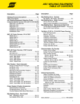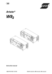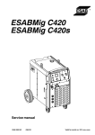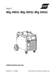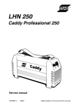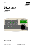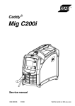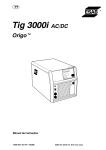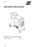
1
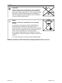
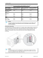
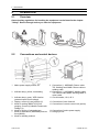
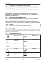
Warrior™ 400i CC/CV
Warrior™ 500i CC/CV
Instruction manual
0463 362 001 GB 20130618
Valid for: serial no. 324-xxx-xxx
TABLE OF CONTENTS
1
SAFETY ................................................................................................................ 4
2
INTRODUCTION ................................................................................................... 7
2.1
Overview ............................................................................................................... 7
2.2
Equipment............................................................................................................. 7
3
TECHNICAL DATA ............................................................................................... 8
4
INSTALLATION................................................................................................... 10
5
6
4.1
General................................................................................................................ 10
4.2
Lifting instructions............................................................................................. 10
4.3
Location .............................................................................................................. 10
4.4
Mains supply ...................................................................................................... 11
OPERATION ....................................................................................................... 14
5.1
Overview ............................................................................................................. 14
5.2
Connections and control devices.....................................................................14
5.3
Connection of welding and return cables........................................................15
5.4
Turning the mains power on/off........................................................................15
5.5
Fan control.......................................................................................................... 15
5.6
Symbols and functions...................................................................................... 15
MAINTENANCE .................................................................................................. 18
6.1
Overview ............................................................................................................. 18
6.2
Power source...................................................................................................... 18
6.3
Welding torch ..................................................................................................... 18
7
FAULT TRACING................................................................................................ 19
8
ORDERING SPARE PARTS ............................................................................... 20
DIAGRAM .................................................................................................................. 21
ORDERING NUMBERS .............................................................................................22
ACCESSORIES .........................................................................................................23
Rights reserved to alter specifications without notice.
0463 362 001
© ESAB AB 2013
1 SAFETY
1
SAFETY
Users of ESAB equipment have the ultimate responsibility for ensuring that anyone who
works on or near the equipment observes all the relevant safety precautions. Safety
precautions must meet the requirements that apply to this type of equipment. The following
recommendations should be observed in addition to the standard regulations that apply to
the workplace.
All work must be carried out by trained personnel well-acquainted with the operation of the
equipment. Incorrect operation of the equipment may lead to hazardous situations which can
result in injury to the operator and damage to the equipment.
1. Anyone who uses the equipment must be familiar with:
○ its operation
○ location of emergency stops
○ its function
○ relevant safety precautions
○ welding and cutting or other applicable operation of the equipment
2. The operator must ensure that:
○ no unauthorised person is stationed within the working area of the equipment when it
is started up
○ no-one is unprotected when the arc is struck or work is started with the equpment
3. The workplace must:
○ be suitable for the purpose
○ be free from drafts
4. Personal safety equipment:
○ Always wear recommended personal safety equipment, such as safety glasses,
flame-proof clothing, safety gloves
○ Do not wear loose-fitting items, such as scarves, bracelets, rings, etc., which could
become trapped or cause burns
5. General precautions:
○ Make sure the return cable is connected securely
○ Work on high voltage equipment may only be carried out by a qualified electrician
○ Appropriate fire extinquishing equipment must be clearly marked and close at hand
○ Lubrication and maintenance must not be carried out on the equipment during
operation
0463 362 001
-4-
© ESAB AB 2013
1 SAFETY
WARNING!
Arc welding and cutting can be injurious to yourself and others. Take precautions
when welding and cutting. Ask for your employer's safety practices which should
be based on manufacturers' hazard data.
ELECTRIC SHOCK - Can kill
•
•
•
•
Install and earth the unit in accordance with applicable standards
Do not touch live electrical parts or electrodes with bare skin, wet gloves or
wet clothing
Insulate yourself from earth and the workpiece
Ensure your working stance is safe
FUMES AND GASES - Can be dangerous to health
•
•
Keep your head out of the fumes
Use ventilation, extraction at the arc, or both, to take fumes and gases away
from your breathing zone and the general area
ARC RAYS - Can injure eyes and burn skin
•
•
Protect your eyes and body. Use the correct welding screen and filter lens and
wear protective clothing
Protect bystanders with suitable screens or curtains
FIRE HAZARD
•
Sparks (spatter) can cause fire. Make sure therefore that there are no
inflammable materials nearby
NOISE - Excessive noise can damage hearing
•
•
Protect your ears. Use earmuffs or other hearing protection. Protect your ears.
Use earmuffs or other hearing protection
Warn bystanders of the risk
MALFUNCTION - Call for expert assistance in the event of malfunction.
Read and understand the instruction manual before installing or operating.
PROTECT YOURSELF AND OTHERS!
WARNING!
Do not use the power source for thawing frozen pipes.
CAUTION!
Read and understand the instruction manual before
installing or operating.
CAUTION!
This product is solely intended for arc welding.
0463 362 001
-5-
© ESAB AB 2013
1 SAFETY
CAUTION!
Class A equipment is not intended for use in residential
locations where the electrical power is provided by the
public low-voltage supply system. There may be potential
difficulties in ensuring electromagnetic compatibility of
class A equipment in those locations, due to conducted
as well as radiated disturbances.
NOTE!
Dispose of electronic equipment at the recycling
facility!
In observance of European Directive 2002/96/EC on
Waste Electrical and Electronic Equipment and its
implementation in accordance with national law, electrical
and/or electronic equipment that has reached the end of
its life must be disposed of at a recycling facility.
As the person responsible for the equipment, it is your
responsibility to obtain information on approved collection
stations.
For further information contact the nearest ESAB dealer.
ESAB can provide you with all necessary welding protection and accessories.
0463 362 001
-6-
© ESAB AB 2013
2 INTRODUCTION
2
INTRODUCTION
2.1
Overview
The Warrior 400i CC/CV and Warrior 500i CC/CV are welding power sources intended for
MIG/MAG welding, as well as for welding with powder filled cored wire (FCAW-S), for TIG
welding, for welding with coated electrodes (MMA) and for arc air gouging.
The power sources are intended for use with the following wire feed units:
•
•
Warrior Feed 304
Warrior Feed 304w
ESAB's accessories for the product can be found in the "ACCESSORIES" chapter of
this manual.
2.2
Equipment
The power source is supplied with:
•
•
•
5 m return cable with earth clamp
3 m mains cable
instruction manual
0463 362 001
-7-
© ESAB AB 2013
3 TECHNICAL DATA
3
TECHNICAL DATA
Warrior 400i CC/CV
Warrior 500i CC/CV
Mains voltage
380-415 V ±10%,
3~ 50/60 Hz
380-415 V ±10%,
3~ 50/60 Hz
Mains supply Sscmin
6.4 MVA
7.2 MVA
Mains supply Zmax
0.025 Ω
0.022 Ω
Primary current I max
MIG/MAG
28 A
37 A
TIG
23 A
30 A
MMA
28 A
38 A
No-load power in energy-saving
mode 6.5 min. after welding
30 W
30 W
Setting range
MIG/MAG
16 A/15 V - 400 A/34 V
16 A/15 V - 500 A/39 V
TIG
5 A/10 V - 400 A/26 V
5 A/10 V - 500 A/30 V
MMA
16 A/20 V - 400 A/36 V
16 A/20 V - 500 A/40 V
Permissible load at MIG/MAG
60 % duty cycle
400 A/34 V
500 A/39 V
100% duty cycle
300 A/29 V
400 A/34 V
Permissible load at TIG
60 % duty cycle
400 A/26 V
500 A/30 V
100% duty cycle
300 A/22 V
400 A/26 V
Permissible load at MMA
60 % duty cycle
400 A/36 V
500 A/40 V
100% duty cycle
300 A/32 V
400 A/36 V
Power factor at maximum current 0.91
0.91
Efficiency at maximum current
88 %
89 %
Electrode types
Basic
Basic
Rutile
Rutile
Cellulosic
Cellulosic
78 V DC
78 V DC
Apparent power at maximum
current
18.0 kVA
24.6 kVA
Active power at maximum
current
16.4 kW
22.5 kW
Operating temperature
-10 to +40°C
-10 to +40°C
Transportation temperature
-20 to +55°C
-20 to +55°C
Open-circuit voltage
without VRD function
Constant sound pressure when <70 db (A)
idling
<70 db (A)
Dimensions l × w × h
712 × 325 × 470 mm
712 × 325 × 470 mm
Weight
58.5 kg
58.5 kg
0463 362 001
-8-
© ESAB AB 2013
3 TECHNICAL DATA
Warrior 400i CC/CV
Warrior 500i CC/CV
Insulation class
H
H
Enclosure class
IP 23
IP 23
Application class
Mains supply, Ssc min
Minimum short circuit power on the network in accordance with IEC 61000-3-12.
Mains supply, Zmax
Maximum permissible line impedance of the network in accordance with IEC 61000-3-11.
Duty cycle
The duty cycle refers to the time as a percentage of a ten-minute period that you can weld or
cut at a certain load without overloading. The duty cycle is valid for 40°C.
Enclosure class
The IP code indicates the enclosure class, i. e. the degree of protection against penetration
by solid objects or water.
Equipment marked IP23 is intended for indoor and outdoor use.
Application class
The symbol
indicates that the power source is designed for use in areas with increased
electrical hazard.
0463 362 001
-9-
© ESAB AB 2013
4 INSTALLATION
4
INSTALLATION
4.1
General
The installation must be carried out by a professional.
4.2
Lifting instructions
WARNING!
Secure the equipment particularly if the ground is
uneven or sloping.
4.3
Location
Position the welding power source such that its cooling air inlets and outlets are not
obstructed.
0463 362 001
- 10 -
© ESAB AB 2013
4 INSTALLATION
4.4
Mains supply
NOTE!
Mains supply requirements
This equipment complies with IEC 61000-3-12 provided that the short-circuit
power is greater than or equal to Sscmin at the interface point between the user's
supply and the public system. It is the responsibility of the installer or user of the
equipment to ensure, by consultation with the distribution network operator if
necessary, that the equipment is connected only to a supply with a short-circuit
power greater than or equal to Sscmin. Refer to the technical data in the Technical
data section.
Make sure that the welding power source is connected to the correct supply voltage and that
it is protected by the correct fuse rating. A protective earth connection must be made in
accordance with regulations.
Table 1. Recommended fuse sizes and minimum cable area Warrior 400i CC/CV
Warrior 400i CC/CV
Mains voltage
380 V 3~ 50/60 Hz
400 V 3~ 50/60 Hz
415 V 3~ 50/60 Hz
Mains cable area
4 × 6 mm²
4 × 6 mm²
4 × 6 mm²
Maximal current
rating Imax
28 A
27 A
25 A
I1eff
MIG/MAG
20 A
19 A
18 A
TIG
16 A
16 A
14 A
MMA
21 A
20 A
19 A
Fuse
anti-surge
25 A
25 A
20 A
type C MCB
25 A
25 A
20 A
0463 362 001
- 11 -
© ESAB AB 2013
4 INSTALLATION
Table 2. Recommended fuse sizes and minimum cable area Warrior 500i CC/CV
Warrior 500i CC/CV
Mains voltage
380 V 3~ 50/60 Hz
400 V 3~ 50/60 Hz
415 V 3~ 50/60 Hz
Mains cable area
4 × 6 mm²
4 × 6 mm²
4 × 6 mm²
Maximal current
rating Imax
38 A
36 A
35 A
I1eff
MIG/MAG
28 A
27 A
26 A
TIG
23 A
22 A
26 A
MMA
29 A
28 A
26 A
Fuse
anti-surge
35 A
35 A
35 A
type C MCB
32 A
32 A
32 A
NOTE!
The mains cable areas and fuse sizes as shown above are in accordance with
Swedish regulations. Use the power source in accordance with the relevant
national regulations.
Connection instruction
The power source is factory set to 400 V AC. If another mains voltage setting is required, the
cable on the printed circuit board has to be moved and put in the correct position. Also the
label, at the rear of the power source, marked with the mains voltage setting must be
updated. This operation must be done by a person who has the appropriate electrical
knowledge.
NOTE!
This power source version is designed for a nominal input voltage from 380 to
415 V AC. ESAB does not recommend a connection of the cable on the circuit
board in the position of 440 , 460 or 575 V AC.
0463 362 001
- 12 -
© ESAB AB 2013
4 INSTALLATION
If the mains cable needs to be changed, the earth connection to the bottom plate and the
ferrites must be installed correctly. See the picture below for the installation order of the
ferrites, washers, nuts and screws.
0463 362 001
- 13 -
© ESAB AB 2013
5 OPERATION
5
OPERATION
5.1
Overview
General safety regulations for handling the equipment can be found in the chapter
"Safety". Read it through before you start the equipment.
5.2
Connections and control devices
1. Mains power supply switch, O/I
2. Indicator lamp, yellow, overheating
3. Indicator lamp, green, VRD function
(reduced open-circuit voltage)
4. Display, current (A) and voltage (V)
5. Knob for setting: MMA/TIG Arc air
gouging: Current (A) Mobile Feed mode:
Voltage (V)
6. Knob for choice of electrode type
7. Knob for inductance (MIG/MAG) and arc
force (MMA):
8. Knob for welding method
0463 362 001
9. Connection (-): MIG/MAG: Return cable
TiG: Welding torch MMA: Return cable or
welding cable
10. Connection (+): MIG/MAG: Welding cable
TIG: Return cable MMA: Welding cable or
return cable
11. Circuit breaker, 10 A, 42 V
12. Connection of wire feed unit
13. Connection of remote control unit (option)
14. Connection of mains power supply
15. Lifting eye bolt
- 14 -
© ESAB AB 2013
5 OPERATION
5.3
Connection of welding and return cables
The power source has two outputs, a positive terminal (+) and a negative terminal (-), for
connecting welding and return cables. The output to which the welding cable is connected
depends on the welding method or type of electrode used.
Connect the return cable to the other output on the power source. Secure the return cable's
contact clamp to the work piece and ensure that there is good contact between the work
piece and the output for the return cable on the power source.
For MMA welding, the welding cable can be connected to the positive terminal (+) or
negative terminal (-) depending on the type of electrode used. The connecting polarity is
stated on the electrode packaging.
5.4
Turning the mains power on/off
Turn on the mains power by turning switch to the ”I” position, see 1 on the picture above.
Turn the unit off by turning the switch to the ”O” position.
Whether the mains power supply is interrupted or the power source is switched off in the
normal manner, welding data will be stored so that it is available next time the unit is started.
CAUTION!
Do not turn off the power source during welding (with load).
5.5
Fan control
The power source has a time control that means that the fans continue to run for 6.5 minutes
after welding has stopped, and the power source switches to energy-saving mode. The fans
start again when welding restarts.
5.6
0463 362 001
Symbols and functions
Placement of lifting
eye
Voltage Reducing
Device
Overheating
protection
Basic electrode
Rutile electrode
Cellulosic electrode
Arc force
Inductance
TIG welding (Live
TIG)
Arc air gouging
- 15 -
© ESAB AB 2013
5 OPERATION
MMA welding
MIG/MAG welding
Wire feed unit
Mobile feed CV
(Constant voltage)
Protective earth
Voltage reducing device (VRD)
The VRD function ensures that the open-circuit voltage does not exceed 35 V when welding
is not being carried out. This is indicated by a lit VRD led.
The VRD function is blocked when the system senses that welding has started.
Contact an authorised ESAB service technician to activate the function.
Overheating protection
The welding power source has overheating protection that operates if the temperature
becomes too high. When this occurs the welding current is interrupted and an overheating
indication lamp is lit.
The overheating protection resets automatically when the temperature has fallen, within
normal working temperature.
Arc force
The arc force is important in determining how the current changes in response to a change in
the arc length. A lower value gives a calmer arc with less spatter.
It only applies to MMA welding.
Inductance
Higher inductance results in a wider weld pool and less spatter. Lower inductance produces
a harsher sound but a stable, concentrated arc.
It only applies to MIG/MAG welding.
TIG welding
TIG welding melts the metal of the workpiece, using an arc struck from a tungsten electrode,
which does not itself melt. The weld pool and the electrode are protected by shielding gas.
"Live TIG-start"
At a ”Live TIG-start” the tungsten electrode is placed against the workpiece. When the
electrode is lifted away from workpiece, the arc is struck at a limited current level.
For TIG welding, the welding power source shall be supplemented with:
•
•
a TIG torch with gas valve
an argon gas cylinder
0463 362 001
- 16 -
© ESAB AB 2013
5 OPERATION
•
•
an argon gas regulator
tungsten electrode
Arc air gouging
With arc air gouging, a special electrode comprising a carbon rod with a copper casing is
used.
An arc is formed between the carbon rod and the workpiece, which melts the material.
Compressed air is supplied so that the melted material is blown away.
For arc air gouging the power source shall be supplemented with:
•
•
•
arc air torches
return cable with clamp
air pressure
Table 3. Recommended for gouging
Electrode
Voltage min.
Voltage max.
6 mm (1/4")
36 V
49 V
8 mm (5/16")
39 V
52 V
10 mm (3/8")
43 V
52 V
Electrode Extension
50 - 76 mm
(2 - 3")
MMA welding
MMA welding may also be referred to as welding with coated electrodes. Striking the arc
melts the electrode, and its coating forms protective slag.
For MMA welding the power source shall be supplemented with:
•
•
welding cable with electrode holder
return cable with clamp
MIG/MAG and self shielded cored wire welding
An arc melts a continuously supplied wire. The weld pool is protected by shielding gas.
For MIG/MAG and self shielded core wire welding, the power source shall be supplemented
with:
•
•
•
•
•
wire feed unit
welding torch
connection cable between power source and wire feed unit
gas cylinder
return cable with clamp
0463 362 001
- 17 -
© ESAB AB 2013
6 MAINTENANCE
6
MAINTENANCE
6.1
Overview
Regular maintenance is important for safe, reliable operation.
Only personnel with the appropriate electrical skills (authorized staff) may remove safety
plates.
CAUTION!
All warranty undertakings from the supplier cease to apply if the customer
attempts any work to rectify any faults in the product during the warranty period.
6.2
Power source
Check regularly that the welding power source is not clogged with dirt. Clogged or blocked
air inlets and outlets can result in overheating.
How often and which cleaning methods apply depend on:
•
•
•
•
the welding process
the arc times
the environment
the surrounding environment
It is normally sufficient to blow down the power source with dry compressed air (reduced
pressure) once a year.
6.3
Welding torch
A regular programme of care and maintenance reduces unnecessary and expensive
downtime.
Each time a wire bobbin is changed, the welding torch should be removed from the power
source and blown clean with compressed air.
The wire end must not have sharp edges when inserted into the wire liner.
For detailed information see instruction manuals for welding torches.
0463 362 001
- 18 -
© ESAB AB 2013
7 FAULT TRACING
7
FAULT TRACING
Try these recommended checks and inspections before sending for an authorized service
technician.
Type of fault
Corrective action
No arc.
•
•
•
•
The welding current is interruppted during
welding.
•
•
•
Check that the mains power supply switch
is turned on.
Check that the mains, welding and return
cables are correctly connected.
Check that the correct current value is
set.
Check the mains power supply fuses.
Check whether the overloading protection
has deployed (indicated on the front).
Check the mains power supply fuses.
Check that the return cable is correctly
fastened.
The overheating protection trips frequently.
•
Make sure that you are not exceeding the
rated data for the power source (i.e. that
the unit is not being overloaded).
Poor welding performance.
•
Check that the welding and return cables
are correctly connected.
Check that the correct current value is
set.
Check that the correct wire or electrode is
used.
Check the mains power supply fuses.
Check the gas pressure in the equipment
connected to the power source.
•
•
•
•
"Err" on display in open circuit mode
•
•
•
0463 362 001
- 19 -
Check the mains power supply fuses.
Check that the voltage on the voltage
selection label on the rear of the power
source is equal to the nominal mains
voltage.
Restart the power source with the main
switch
© ESAB AB 2013
8 ORDERING SPARE PARTS
8
ORDERING SPARE PARTS
Repair and electrical work should be performed by an authorised ESAB service technician.
Use only ESAB original spare and wear parts.
The Warrior 400i CC/CV and Warrior 500i CC/CV are designed and tested in accordance
with international and european standards IEC/EN 60974-1 and IEC/EN 60974-10. On
completion of service or repair work, it is the responsibility of the person(s) performing the
work to ensure that the product still complies with the requirements of the above standard.
Spare parts may be ordered through your nearest ESAB dealer, see the last page of this
document.
0463 362 001
- 20 -
© ESAB AB 2013
DIAGRAM
DIAGRAM
0463 362 001
- 21 -
© ESAB AB 2013
ORDERING NUMBERS
ORDERING NUMBERS
Ordering number
Denomination
Type
Notes
0465 350 884
Welding power source Warrior 400i CC/CV
380-415 V
0465 350 883
Welding power source Warrior 500i CC/CV
380-415 V
0464 254 001
Spare parts list
0464 523 001
Service manual
Technical documentation is available on the Internet at www.esab.com
0463 362 001
- 22 -
© ESAB AB 2013
ACCESSORIES
ACCESSORIES
0465 250 880
Warrior™ Feed 304
0465 250 881
Warrior™ Feed 304w,
with water cooling
0558 005 728
MobileFeed 300 AVS
0459 491 896
Remote control unit AT1
MMA and TIG current
0459 491 897
Remote control unit AT1 CF
MMA and TIG: course and fine setting of
current
Remote control cable 12 pole - 8 pole
0459 552 880
5m
0459 552 881
10 m
0459 552 882
15 m
0459 552 883
25 m
0463 362 001
- 23 -
© ESAB AB 2013
ACCESSORIES
0465 424 880
Remote outlet kit
0465 416 880
Wheel kit
0465 510 880
Trolley
0465 427 880
Cooling unit
Connection set, 70 mm², 19 poles
0459 836 880
1.7 m
0459 836 881
5m
0459 836 882
10 m
0459 836 883
15 m
0459 836 884
25 m
0459 836 885
35 m
Connection set water, 70 mm², 19 poles
0459 836 890
1.7 m
0459 836 891
5m
0459 836 892
10 m
0459 836 893
15 m
0459 836 894
25 m
0459 836 895
35 m
0463 362 001
- 24 -
© ESAB AB 2013
ACCESSORIES
Connection set, 95 mm², 19 poles
0459 836 980
1.7 m C
0459 836 981
5mC
0459 836 982
10 m C
0459 836 983
15 m C
0459 836 984
25 m C
0459 836 985
35 m C
Connection set water, 95 mm², 19 poles
0459 836 990
1.7 m A
0459 836 991
5mC
0459 836 992
10 m A
0459 836 993
15 m C
0459 836 994
25 m C
0459 836 995
35 m C
TIG torches
0700 300 539
TXH™ 151 V, OKC50, 4 m A
0700 300 545
TXH™ 151 V, OKC 50, 8 m A
0700 300 553
TXH™ 201 V, OKC 50, 4 m A
0700 300 556
TXH™ 201 V, OKC 50, 8 m
Arc air torches
0468 253 880
Flair 600 incl monocable 2.5 m A
0468 253 016
Torch only A
0468 253 015
Monocable only A
0468 253 881
Flair 1600 incl monocable 2.5 m A
0468 253 036
Torch only A
0468 253 035
Monocable only A
0463 362 001
- 25 -
© ESAB AB 2013
ESAB subsidiaries and representative offices
Europe
AUSTRIA
ESAB Ges.m.b.H
Vienna-Liesing
Tel: +43 1 888 25 11
Fax: +43 1 888 25 11 85
BELGIUM
S.A. ESAB N.V.
Brussels
Tel: +32 2 745 11 00
Fax: +32 2 745 11 28
BULGARIA
ESAB Kft Representative Office
Sofia
Tel: +359 2 974 42 88
Fax: +359 2 974 42 88
THE CZECH REPUBLIC
ESAB VAMBERK s.r.o.
Vamberk
Tel: +420 2 819 40 885
Fax: +420 2 819 40 120
DENMARK
Aktieselskabet ESAB
Herlev
Tel: +45 36 30 01 11
Fax: +45 36 30 40 03
FINLAND
ESAB Oy
Helsinki
Tel: +358 9 547 761
Fax: +358 9 547 77 71
GREAT BRITAIN
ESAB Group (UK) Ltd
Waltham Cross
Tel: +44 1992 76 85 15
Fax: +44 1992 71 58 03
ESAB Automation Ltd
Andover
Tel: +44 1264 33 22 33
Fax: +44 1264 33 20 74
FRANCE
ESAB France S.A.
Cergy Pontoise
Tel: +33 1 30 75 55 00
Fax: +33 1 30 75 55 24
GERMANY
ESAB GmbH
Solingen
Tel: +49 212 298 0
Fax: +49 212 298 218
HUNGARY
ESAB Kft
Budapest
Tel: +36 1 20 44 182
Fax: +36 1 20 44 186
NORWAY
AS ESAB
Larvik
Tel: +47 33 12 10 00
Fax: +47 33 11 52 03
POLAND
ESAB Sp.zo.o.
Katowice
Tel: +48 32 351 11 00
Fax: +48 32 351 11 20
PORTUGAL
ESAB Lda
Lisbon
Tel: +351 8 310 960
Fax: +351 1 859 1277
ROMANIA
ESAB Romania Trading SRL
Bucharest
Tel: +40 316 900 600
Fax: +40 316 900 601
RUSSIA
LLC ESAB
Moscow
Tel: +7 (495) 663 20 08
Fax: +7 (495) 663 20 09
SLOVAKIA
ESAB Slovakia s.r.o.
Bratislava
Tel: +421 7 44 88 24 26
Fax: +421 7 44 88 87 41
SPAIN
ESAB Ibérica S.A.
Alcalá de Henares (MADRID)
Tel: +34 91 878 3600
Fax: +34 91 802 3461
SWEDEN
ESAB Sverige AB
Gothenburg
Tel: +46 31 50 95 00
Fax: +46 31 50 92 22
ESAB International AB
Gothenburg
Tel: +46 31 50 90 00
Fax: +46 31 50 93 60
SWITZERLAND
ESAB AG
Dietikon
Tel: +41 1 741 25 25
Fax: +41 1 740 30 55
UKRAINE
ESAB Ukraine LLC
Kiev
Tel: +38 (044) 501 23 24
Fax: +38 (044) 575 21 88
North and South America
ARGENTINA
CONARCO
Buenos Aires
Tel: +54 11 4 753 4039
Fax: +54 11 4 753 6313
BRAZIL
ESAB S.A.
Contagem-MG
Tel: +55 31 2191 4333
Fax: +55 31 2191 4440
www.esab.com
Africa
EGYPT
ESAB Egypt
Dokki-Cairo
Tel: +20 2 390 96 69
Fax: +20 2 393 32 13
MEXICO
ESAB Mexico S.A.
Monterrey
Tel: +52 8 350 5959
Fax: +52 8 350 7554
SOUTH AFRICA
ESAB Africa Welding & Cutting
Ltd
Durbanvill 7570 - Cape Town
Tel: +27 (0)21 975 8924
USA
ESAB Welding & Cutting
Products
Florence, SC
Tel: +1 843 669 44 11
Fax: +1 843 664 57 48
Asia/Pacific
AUSTRALIA
ESAB South Pacific
Archerfield BC QLD 4108
Tel: +61 1300 372 228
Fax: +61 7 3711 2328
CHINA
Shanghai ESAB A/P
Shanghai
Tel: +86 21 2326 3000
Fax: +86 21 6566 6622
INDIA
ESAB India Ltd
Calcutta
Tel: +91 33 478 45 17
Fax: +91 33 468 18 80
INDONESIA
P.T. ESABindo Pratama
Jakarta
Tel: +62 21 460 0188
Fax: +62 21 461 2929
JAPAN
ESAB Japan
Tokyo
Tel: +81 45 670 7073
Fax: +81 45 670 7001
SINGAPORE
ESAB Asia/Pacific Pte Ltd
Singapore
Tel: +65 6861 43 22
Fax: +65 6861 31 95
THE NETHERLANDS
ESAB Nederland B.V.
Amersfoort
Tel: +31 33 422 35 55
Fax: +31 33 422 35 44
UNITED ARAB EMIRATES
ESAB Middle East FZE
Dubai
Tel: +971 4 887 21 11
Fax: +971 4 887 22 63
CANADA
ESAB Group Canada Inc.
Missisauga, Ontario
Tel: +1 905 670 02 20
Fax: +1 905 670 48 79
MALAYSIA
ESAB (Malaysia) Snd Bhd
USJ
Tel: +603 8023 7835
Fax: +603 8023 0225
ITALY
ESAB Saldatura S.p.A.
Bareggio (Mi)
Tel: +39 02 97 96 8.1
Fax: +39 02 97 96 87 01
SOUTH KOREA
ESAB SeAH Corporation
Kyungnam
Tel: +82 55 269 8170
Fax: +82 55 289 8864
Distributors
For addresses and phone
numbers to our distributors in
other countries, please visit our
home page
www.esab.com