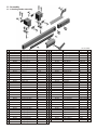
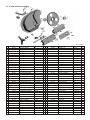
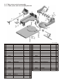
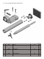
1
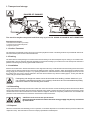
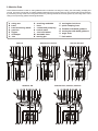
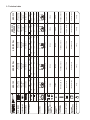
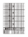
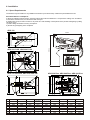
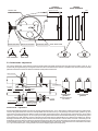
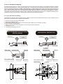
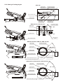
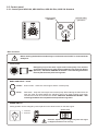
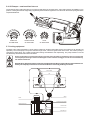
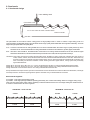
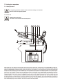
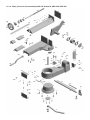
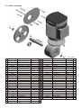
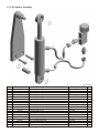
INSTRUCTION MANUAL
ARG 180 • ARG 200 Plus • ARG 220 Plus • ARG 230 Standard • ARG 230
ARG 230 Plus • ARG 240 • ARG 240 Plus • ARG 290 Plus
Pilous − pásové pily, spol. s r.o., Kšírova 118 b, 619 00 Brno, Czech Republic
tel.: 00 420 543 25 20 10, fax: 00 420 543 25 20 11, e−mail:[email protected]
Dear customer,
thank you for buying our product and we wish you a lot of success with it. For proper machine function please pay an
attention to this instruction manual.
© 2004 All rights particularly the right to make copies of, to distribute and translate this instruction manual are reserved.
No part of this instruction manual may be reproduced in any form (printing, microfilm or others) or sorted, processed,
copied or distributed by using electronic systems without permission of PILOUS.
Content :
0.
In general
7.
Putting into operation
0.1.
0.2.
0.3.
0.4.
Safety provisions
Scope of use / use by determination
Requirements concerning operators
Requirements concerning machines safety equipments
Protective covers
7.1.
7.2.
Safety control
First cut
0.5.
1.
1.1.
1.2.
1.3.
1.4.
1.5.
Transport and storage
2.
Machine data
3.
Technical data
4.
4.1.
4.2.
4.3.
Installation
5.
Machine description
Surface treatment
Packing
Installation
Dismantling
Disposal
Space requirements
Machine installation
Connection to energy supplies
5.1. Band guide
5.2. Band exchange, tensioning and adjustment
5.3. Guide heads - adjustment
5.4. Vice - Workpiece clamping
5.4.1. Vice side clearance setting
5.4.2. Setting of cutting angle
5.5. Control panel
5.5.1. Control panel ARG 180, ARG 200 Plus,
ARG 220 Plus, ARG 230 Standard
5.5.2. Control panel ARG 230, ARG 230 Plus,
ARG 240, ARG 240 Plus, ARG 290 Plus
5.6. Oil Damper - saw band feed into cut
5.7. Cooling equipment
6.
Saw bands
6.1.
6.2.
6.3.
6.4.
6.5.
6.6.
Saw band design
Band tooth selection
Workpiece clamping
Running-in the bands
Factors influencing band life
Recommended values for cutting
8.
Machine maintenance
8.1.
8.2.
Maintenance and control
Repairs
9.
Errors - reasons and elimination
10.
Electrical scheme and device lay-out
10.1. Electrical scheme
ARG 180, 200 Plus, 220 Plus, 230 Standard
10.2. Electrical scheme ARG 230, ARG 230 Plus,
ARG 240, ARG 240 Plus, ARG 290 Plus
10.3. Electrical device lay-out
180, 200 Plus, 220 Plus, 230 Standard
10.4. Electrical device lay-out ARG 230, ARG 230 Plus,
ARG 240, ARG 240 Plus, ARG 290 Plus
11.
Assembly
11.1. Guiding heads assembly
11.2. Idler wheel assembly
11.3. Table, pivot and vice assembly
11.3.1. Table, pivot and vice assembly ARG 180
11.3.2. Turning table and pivot assembly
ARG 200 Plus, ARG 220 Plus
11.3.3. Vice assembly ARG 200 Plus, ARG 220 Plus
11.3.4. Table, pivot and vice assembly
ARG 230 Standard, ARG 230, ARG 240
11.3.5. Table, turning table, pivot and vice assembly
ARG 230 Plus, ARG 240 Plus, ARG 290 Plus
11.4. Drive assembly
11.5. Oil damper assembly
11.6. Coolant assembly
0. In general
This instruction manual provides the users assistance and information about the PILOUS bandsaw and the possibilities of use
corresponding to its purpose. The instruction manual contains important instructions for a safe, adequate and economically efficient
operation. Observing the operating instructions will prevent hazards, reduce the repair and outage time costs, and increase the
machine reliability of a system. The instruction manual must always be available at the machine site. The instruction manual must be
read and used by the staff entrusted with the machine installation, transport and storage, use/operation, maintenance and disposal.
In addition to the instruction manual and the binding rules related to accident prevention valid in the user´s country and at the service
site. It is also necessary to observe the approved rules for safe and professional work.
Warranty letter - service
Warranty letter is a separate part of the instruction manual.
Warranty period length: see warranty letter.
Terms of validity of the warranty letter :
• Machine transport, manipulation and storage according to the instruction manual.
• Machine usage, operation and maintenance according to the instruction manual.
• Machine connection to the electrical grid supply according to the instruction manual.
The warranty letter does NOT include :
•The machine user´s or third person violent and mechanical machine damage.
• Remediless event (elementary disaster).
• Machine damage during transport.
• Machine storage or placing in wet, chemical or otherwise dangerous environment.
Address any possible comments on the warranty letter by fax, or mail to the address shown on the warranty
letter.
Notice for the user:
The seller is obliged to issue warranty letter to the user when the product is dispatched. The warranty letter must be signed and
confirmed by the seller´s stamp with the date of issue and product serial number. The seller is obliged to introduce the product to the
user.
Data needed to apply for the warranty (after warranty) machine repair:
• Machine type
• Warranty letter number (same as machine serial number)
• Warranty letter issue date
0.1. Safety provisions
The machine design complies with the technical status and the approved safety and technical rules. In spite of this the user's or the
third persons' health can be endangered and/or the machine or other tangible goods may be unfavorably influenced during the
operation of the machine. In order to prevent such hazards it is unconditionally necessary to observe the safety instructions in this
instruction manual. These safety instructions must be read and understood by the respective persons before the machine has been
put into operation. Failure to observe these instructions may cause serious property damage and damage to health! The safety
instructions are marked in this instruction manual with safety symbols / danger spot signs.
Dangerous place caution be very careful!
Use eyes and ears protection!
Necessary to use high boots or hard duty
shoes with protective steel forepart and
anti-sliding sole!
Caution of dangerous electrical voltage!
Use protective gloves!
Read the instruction manual carefully and make
sure you understood its content before using the
machine!
0.2. Scope of use / use by determination
The machine is designed exclusively for normalized metallic materials. Any other use is considered as not adequate to the purpose.
The manufacturer is not responsible for damage due to such a risk. The use complying with the purpose includes also observing the
operating instructions, checking and maintenance conditions.
Examples of cutting materials: structual steel • case-hardering steel • free-cutting steel • heat treatment steel • antifriction bearing
steel • spring steel • tool steel • high-speed steel • copper • brass • cast steel • cast iron • aluminum •plastic materials
0.3. Requirements concerning operators
The machine may only be operated by persons instructed in safety at work and technically trained!
The machine may only be operated if in perfect condition with respect to technical safety. The user is obliged to check the machine for
visually ascertainable damages and failures at least once per shift. Any changes, failures and damages of protective covers,
changes of the machine behavior endangering the safety should be immediately reported to the superior. Wait for the decision about
the repair and the repeated putting into operation. No protective covers may be removed, moved, put out of operation or changed
during the machine operation. Otherwise the guarantee claims have no effect. If any protective has to be removed during operation
or maintenance, secure the main switch in the „OFF“ position by a padlock or disconnect the bandsaw from the mains.
Only electricians or persons instructed in electrotechnical work and supervised by electrical specialists are
allowed to open the electric equipment housings and to work on the electric equipment!
• while working with the machine remove all free clothing and cover long hair
• make sure that all other persons are at least 5 m far away from the saw blade and protect them from chips and possibility of saw
blade breaking
• make sure that all persons helping you with know all safety rules
• safety rules must be showed clearly in the working area
• keep your hands far enough from the saw blade and never adjust the saw blade when the engine is on. Switch off the engine and
secure it against running before any manipulation with the saw blade
0.4. Requirements concerning machines - safety equipments
CAUTION - DANGER OF INJURY!
The saw band is not covered in the machining zone!
Wait until the saw band is in standstill before opening
the protective covers.
Danger in working zone of the swing arm!
Do not use the machine when tired, overwork, under medicines, drugs or alcohol!
The horizontal bandsaw is a machine tool. For machining the saw band must penetrate into the workpiece in the metal-cutting zone.
The covers protecting against contact with the saw band may therefore be installed only outside the metal-cutting zone.
0.5. Protective Covers
Outside the metal-cutting zone the saw band and the saw band discs are protected against contact. The protective covers may be
only removed when the main switch is off and secured against switching on or when the machine is disconnected from the mains. The
emergency shut down of the machine is effected by depressing the TOTAL STOP push-button. Putting the machine into operation
again is only possible after pulling and unlocking the push-button manually.
Manual machine cleaning and waste remove while the machine is running is forbidden. The working place
must have first aid set. When working with the machine proper work clothes, boots and protective
instruments(eyes and ears protections, gloves, proper work boots) must be used. Abide clean air and work
space rules.
1. Transport and storage
DANGER OF DAMAGE!
The machine maybe transported and lifted only by a fork lift. USING A CRANE IS NOT PERMITTED!
Standard accessories:
1 bimetallic saw band M 42 (mounted)
1 coolant unit with a metal chips tank
1 length stop 500 mm
1.1. Surface Treatment
The machine is provided with a primer and a two-component polyethane varnish. The sliding surfaces are provided with antirust oil.
The other machine parts are zinc coated or blackened.
1.2. Packing
The basic element of the package is a wooden frame which according to the kind of dispatch may be crating or an overseas case.
Approximately 100 mm clearance should be provided for transport and loading by a fork lift truck. For the transport the machine is
packed in a stretching foil protecting against weather influences.
1.3. Installation
Remove the wooden frame. Position the machine at site. Align the machine by a water level and four M12 setting screws in the base
corners. Remove antirust protection and dust from the sliding surfaces and apply oil again. Attach the length stop. Make sure that
energy supply is connected (see chapter 4.3). Opening the base door, make sure that the coolant discharge pipe has not come off
the coolant tank cover and is correctly attached in the tank. Fill the machine tray with the coolant (approx. 15 litre), the fluid will
continuously pour into the tank in the base.
Endangering with dangerous matters cannot be excluded when handling coolants. Observe in your
own interest the manufacturer's and/or your company's instructions and recommendations/operating
instructions related to safe handling with coolants.
1.4. Dismantling
Empty and clean the metal chips tank and the coolant tank. Clean the machine. Provide the sliding surfaces with antirust oil. Make
sure that the machine has been disconnected from electrical energy supply. Prepare the swing arm protection for transport. Lift the
machine and screw on the wooden frame. Provide a clearance of approx. 100 mm for transport by a fork lift truck. Check whether all
protective covers of the machine are screwed on. Enclose the machine accessories.
CAUTION : Used coolants are special waste!
Disconnecting the machine from the electrical energy supply may be only carried out
by electricians!
1.5. Disposal
When the machine has been definitely put out of operation, it should be disposed of in accordance with the provisions valid in the
respective country. We recommend to contact a company specialized in waste disposal.
2. Machine Data
This horizontal bandsaw is used for cutting different kinds of material. The swing arm raising, the work feeding, clamping and
removal are carried out manually. An endless welded metallic band serves as the cutting tool. The band is tensioned mechanically
by a tensioning running wheel. The running wheel is driven by a driving wheel driven via worm gearbox by a two-stage motor. In the
cutting zone it is precisely guided in the band guide heads.
A
B
C
D
E
F
G
swing arm
band
band tensioning wheel
gear box
engine
oil damper
vice
H
I
J
K
L
M
N
revolving worktable
base
coolant and pump tray
control panel
vice hand wheel
worktable lever
moving jaw
ARG 180
C
L K
G
O R B N
M I
J
Q
A D
F
E
C
T
K
G O R B
L
ARG 230, 240
L
P K
O R
G
I
P quick clamping lever
Q fixed bar with band guidance
R moving bar with band guidance
S angle scale
T limit switch
ARG 200 Plus, 220 Plus
S H
C
O moving bar lock lever
B N S Q
J
H
I M J
N
S H
Q F
ARG 230 Standard
A D
E
G O R B
C
T
L
K
I
N S
J
Q
H
M T
ARG 230 Plus, 240 Plus, 290 Plus
F A D
M T
E
C
L
P K
O R S N
G
I
J
B Q
H
F A D
M T
F A D
E
E
45°
45°
60°
MACHINE WEIGHT
MACHINE
DIMENSSIONS
COOLANT TANK
OIL INSIDE
THE DAMPER
100
195 kg
1300×660×1500
approx. 15 lite
PARAMOL HM 46
900 mm
60°
VICE WORK
HEIGHT
60°
245 mm
45°
90°
SAW BAND
GUIDING WHEELS
DIAMETER
45°
150
100
60°
200
200
90°
240x140 150x130 100×160 245x150
180
2220×13×0,9
60°
90°
a
a
150
45°
SAW BAND SIZE
ARM SWING
a
a×b b
a
180
90°
50 / 95 m/min
BAND SPEED
[mm]
400 V, 50 Hz
0,09 kW
400 V, 50 Hz
0,09 kW
PUMP ENGINE
CUTTIN RANGE
400 V, 50 Hz
0,75 / 0,95 kW
400 V, 50 Hz
0,3 / 0,45 kW
MAIN ENGINE
45°
90°
45°
60°
160x115
145
160
45°
220 kg
1350×660×1450
approx. 15 litre
PARAMOL HM 46
895 mm
300 mm
2490x20x0,9
60°
140x90
110
130
45°
40 / 80 m/min
ARG 200 Plus
ARG 180
90x120
90
90
60°
150
160
45°
160
180
45°
100
100
60°
45°
45°
60°
250 kg
1400×660×1400
approx. 15 litre
PARAMOL HM 46
895 mm
300 mm
2600x27x0,9
60°
90°
265x150 160x130 200x140 115x100
220
220
90°
40 / 80 m/min
400 V, 50 Hz
0,09 kW
400 V, 50 Hz
0,9 / 1,4 kW
ARG 220 Plus
45°
90°
45°
60°
125x80
120
125
45°
280 kg
1300×620×1400
approx. 15 litre
PARAMOL HM 46
910 mm
300 mm
2465x27x0,9
60°
220x105
195
220
90°
40 / 80 m/min
400 V, 50 Hz
0,09 kW
400 V, 50 Hz
0,75 / 0,95 kW
ARG 230
STANDARD
45°
90°
45°
60°
125x80
120
125
45°
350 kg
1300×900×1400
approx. 15 litre
PARAMOL HM 46
910 mm
300 mm
2465x27x0,9
60°
220x105
195
220
90°
40 / 80 m/min
400 V, 50 Hz
0,09 kW
400 V, 50 Hz
0,75 / 0,95 kW
ARG 230
3. Technical data
45°
45°
60°
MACHINE WEIGHT
MACHINE
DIMENSSIONS
COOLANT TANK
OIL INSIDE
THE DAMPER
430 kg
1300×900×1400
approx. 15 litres
PARAMOL HM 46
910 mm
60°
VICE WORK
HEIGHT
60°
90°
125x100
120
300 mm
45°
110x60
110
125
45°
SAW BAND
GUIDING WHEELS
DIAMETER
45°
215x80
190
100
45°
2465x27x0,9
60°
90°
a
a
215
90°
SAW BAND SIZE
ARM SWING
a
a×b b
a
[mm]
75x80
70
75
60°
180
200
45°
115
120
60°
45°
45°
60°
390 kg
1400x900x1330
approx. 15 litres
PARAMOL HM 46
910 mm
300 mm
2710×27×0,9
60°
90°
290x180 190x150 115×115
220
240
90°
140
170
45°
180
190
45°
40 / 80 m/min
120
125
60°
290
290
90°
190
220
45°
230
240
45°
40 / 80 m/min
400 V, 50 Hz
0,09 kW
400 V, 50 Hz
0,9 / 1,7 kW
ARG 290 Plus
155
160
60°
45°
45°
60°
470 kg
1400×900×1330
approx. 15 litres
PARAMOL HM 46
910 mm
300 mm
2710x27x0,9
60°
90°
45°
45°
60°
540 kg
1600×950×1600
approx 15 litres
PARAMOL HM 46
915 mm
355 mm
3110x27x0,9
60°
90°
300x160 160x100 190x130 120x120 360x290 230x125 250x290 155x155
240
240
90°
40 / 80 m/min
BAND SPEED
CUTTING RANGE
400 V, 50 Hz
0,09 kW
400 V, 50 Hz
0,09 kW
PUMP ENGINE
40 / 80 m/min
400 V, 50 Hz
0,9 / 1,4 kW
400 V, 50 Hz
0,9 / 1,4 kW
400 V, 50 Hz
0,75 / 0,95 kW
MAIN ENGINE
400 V, 50 Hz
0,09 kW
ARG 240 Plus
ARG 240
ARG 230 Plus
4. Installation
4.1. Space Requirements
The machine may be installed on any suitable even hall floor (concrete surface). Observe the permissible floor load.
Recommendations / assumptions:
a) Allow for sufficient work feed space, work removal and the machine maintenance - the operators' working area should be 1
m around the machine and 0,5 m around the roller conveyor.
b) Install roller conveyors and/or a case for cut pieces for a safe handling of work pieces and to prevent endangering by falling
cut pieces, if any.
c) Install a lifting mechanism for heavy work pieces.
d) Provide for good lighting of the workplace.
ARG 180
B
90
0
-6
0
0
F
E
D max.
C max.
A
F
E
H
G
B
45 °
ARG 200 PLUS, ARG 220 PLUS
6 0°
A
ARG 230 Plus, ARG 240 Plus, ARG 290 Plus
B
F
E
F
E
H
G
B
4 5°
ARG 230 Standard, ARG 230, ARG 240
60 °
4 5°
A
A
A
B
C
D
E
F
G
H
ARG 180
720
625
1800
1240
1050
1160
x
x
ARG 200 Plus ARG 220 Plus
720
720
625
625
1820
1830
1230
1230
1100
950
1250
1650
920
1070
980
1230
ARG 230
Standard
730
635
1910
1580
1028
1238
x
x
ARG 230
845
940
1880
1633
1115
1190
x
x
ARG 230 Plus
850
950
1895
1621
1030
1030
894
1330
ARG 240
845
940
1940
1795
1125
1200
x
x
ARG 240 Plus ARG 290 Plus
850
905
950
1005
1945
2040
1745
1690
1098
1210
1098
1270
1258
1335
1368
1430
4.2. Machine installation
Protect the machine against humidity, rain and dust!
The machine may be operated in the ambient temperature between +5° and +40°C. The average temperature must not exceed
+35°C over the period of 24 hours. In temperatures below +5°C the conventional coolant should be replaced by a fluid working with
respective temperatures.
4.3. Connection to energy supplies
This work may only be carried out by electricians!
Make sure that the voltage of the electrical grid, voltage protection and connection voltage is according to requirements in chapter 3.
Technical data. When connecting machines into the electrical grid 3NPe, 50 Hz, 400 V, TN-S notice carefully the colored cables
marking : L1 Black, L2 brown, L3 black, N blue, P/E yellow/green. In case of wrong connection of neutral or protective cable the
machine electric parts may be damaged and injury by electrical current may occur! The lead-in cable of the machine should be
connected to a protected 16 A socket, in case of a direct connection to the mains the cable should be provided with a lockable main
switch. In case of wrong direction of turning of the motor switch together cables L1 black and L2 brown.
Failure to observe this causes the bandsaw drive motor and the coolant pump running in wrong
directions. Possibility of machine destruction!
5. Machine description
5.1. Band guide
Before and after the cut the saw band is guided in two guide heads provided with eccentrically arranged bearings enabling an easy
setting of the band in comparison with the guiding on moving wheels and guided in the hard-metal guides on both sides and on the
upper band edge. The right-hand guide head is fixed. The left-hand guide head mounted on the guide bar is moving and is fed as
close as possible to the work. It is provided with a protective cover as far as the machining zone.
5.2. Band exchange, tensioning and adjustment
To achieve perfect cutting function, surface quality and workpiece correct measures, in time band exchange is needed. Blunt blade
may cause higher energy consumption, inclined cuts and cut surface roughness. One of the most important factors for band life time
and the cut quality is the band correct and enough tensioning.
Caution! It can only be done when the main switch is off and secured against switching
on again or when the machine is disconnected from the mains.
Caution! Danger of injury by the sharp band teeth. Use protective gloves. Do not
touch the guide wheels and the band.
Turn OFF the main switch and secure the machine against switching ON again during band exchange. Close the oil damper valve
(see chapter 5.6.). Raise the arm to position 20 mm above vice fixed jaw. Take off the arm rear cover. Loosen the tensioning handle
and the tensioning wheel and thus the whole band. Take off the band from the running wheels and out of the guide heads (see chapter
5.3.). Insert the new band in the guide heads. Put the band on the running wheels and tighten the tensioning handle so that the
belleville washers will be pressed completely (no light going through them). Close the band cover, turn ON main switch and witch the
speed to the minimum. Press start the button to run the band so it turns one round. Turn OFF a main switch and secure the machine
against running again. Open the band cover and check if the band is correctly guided on the running wheels (see a picture below). If
the band is not correctly set on the running wheels loosen the tensioning handle and with a wheel swing screw correct (see picture
below). Tighten the tensioning handle again. Close the band cover. Exam the band run again. Turn OFF main switch, open band
cover and check the setting of band on the running wheels. According to need repeat this cycle till the band is set on the running
wheels properly. Then close the band cover turn ON main switch and make first cut.
CORRECT
BAND GUIDANCE
WRONG
BAND GUIDANCE
0 mm
approx. 0,5-3 mm
CONTROL HOLE
OF BAND GUIDANCE
TENSIONING HANDLE
BAND TENSIONING
BELLEVILLE WASHERS
TENSIONING WHEEL
WHEEL SWING SCREW
TIGHTEN SCREW
BAND LOOSE
LOOSE SCREW
5.3. Guide heads - adjustment
The correct adjustment of the bearings and hard-metal guides principally influences the band life and the quality of the cut. The
eccentrically arranged bearings of the guide heads must be so set that the band surface is parallel to the surface of the hard-metal
plates and that there is minimum clearance between these plates and the band.
GUIDING HEAD SCREW
FIXED
HARDMETAL GUIDANCE
ADJUSTABLE
GUIDE BAR
HARDMETAL SCREW
GUIDE HEAD
EXCENTR SCREW
FIXED BAR
FIXED HARDMETAL
GUIDANCE
SAW BAND
EXCENTRIC BEARINGS
HARDMETAL SCREW
Correct band
guidance
between bearings
into middle
Incorrect band
guidance
PRESSING HARDMETAL
GUIDANCE
HARDMETAL GUIDANCE
WITH SETTING SCREW
Guide heads - adjustment
Set the adjustable guide head to be far from the fixed guide head approx. 20 cm. Remove the coolant hoses from the guide heads.
Unscrew the guide heads from the fixed and adjustable bars and turn them by 180°(bearings and hard metals guidance up) and
screw them to the bars. Make sure that the heads are upright mounted to the bars in the same height. Check the fixity of hard metal
tightening. Take old band (approx. 30 cm of it) and put it in the guide heads between hard metals and bearings. Set the pressing hard
metal guidance by width adjusting screws so the band moves inside the hard metals without any clearance but without rub. Set the
bearings to the band in away so the band moves through them moves them all but do not shear and is not loosen. The bearings must
be drifted by the band. Make sure all screws are tightened properly. Take away the guide heads from the bars and put the band on the
running wheels properly. Put on the guide heads on the band and fix them on the bars. Close the band cover and switch main switch
on . Try to run the band on the running wheels. If the band is slipping adjust the band properly.
5.4. Vice - Workpiece Clamping
The machine design allows for cutting the material under various angles without its handling. The material is permanently clamped
between the fixed gripping jaw and the moving gripping jaw . The adjustment of the required cutting angle is made by turning the
whole arm including the revolving worktable after releasing the worktable eccentric lever. When the required angle has been set
(acc. to the angle scale), secure the revolving worktable by tightening the worktable quick-clamping lever. The stop bolts serve for a
stable setting of the limit angles. The quick-clamping lever (ONLY ARG 230, 230PLUS, 240, 240PLUS and 290PLUS) enables a
comfortable and sufficient workpiece clamping. When materials of equal dimensions are being cut, it enables the releasing of the
material necessary for the feed and re-clamping only by the lever without using the handwheel.
5.4.1. Vice side clearance setting
Models ARG 230 Standard, ARG 230, ARG 230 Plus, ARG 240, ARG 240 Plus and ARG 290 Plus only. On other models the vice is
set from the manufacturer for the complete machine lifetime.
•
‚
ƒ
„
…
†
‡
o pen the vice to the maximum possible length
loosen lock nut M8 and screws
start tightening the first screw ( starting from the vice jaw) till you feel that you reached the vice ribbon
secure the lock nut in this position
drift the vice moving part to the same position in which previous screw was adjusted
re peat steps ƒ, „, …
continue like above till the vice is set
ARG 230 Standard (without quick clamping),
ARG 230, ARG 240
CONTER NUT
ADJUSTING SCREW
OF VICE
ARG 240 Plus, ARG 290 Plus
CONTER NUT
ADJUSTING SCREW
OF VICE
“T” GROOVE
WHEEL HANDLE
VICE MOVING BODY
QUICK CLAMPING LEVER
(except ARG 230 Standard)
MOVING JAW
FIXED JAW
WHEEL HANDLE
WORKPIECE
QUICK CLAMPING LEVER
SETTING SCREW
VICE MOVING BODY
MOVING JAW
“T” GROOVE
FIXED JAW
WORKPIECE
5.4.2. Setting of Cutting Angels
ARG 180
ARM SETTING
FIXED STOP 60°
CONTINUOUS RANGE
OF ARM ADJUSTMENT
ARM LOCKING LEVER
90°- 60°
ANGLE SCALE
REVOLVING
WORK TABLE
ARM SETTING
FIXED STOP 90°
ARG 200 Plus, ARG 220 Plus
CONTINUOUS RANGE
OF ARM ADJUSTMENT
REVOLVING
WORK TABLE
90° - 60°
ARM LOCKING LEVER
ANGLE SCALE
90° - 45°
ARM BACKSTOP
SCREW
ARM LOCKING LEVER
ARG 230 Standard, ARG 230, ARG 240 (60°)
REVOLVING
WORK TABLE
CONTINUOUS RANGE
OF ARM ADJUSTMENT
ARM SETTING
FIXED STOP 90°
90°- 45°
(ARG 240 - 60°)
ANGLE SCALE
ARM LOCKING LEVER
ARM SETTING FIXED STOP 45°
ARG 240 ARM SETTING FIXED STOP 60°
ARM BACKSTOP
SCREW
DOWN END SWITCH
SETTING SCREW
ARG 230 Plus, ARG 240 Plus, ARG 290 Plus
REVOLVING
WORK TABLE
CONTINUOUS RANGE
OF ARM ADJUSTMENT
90° - 60°
ARM SETTING
FIXED STOP 45°
ANGLE SCALE
ARM LOCKING LEVER
90° - 45°
ARM SETTING FIXED STOP 60°
ARM BACKSTOP
SCREW
DOWN END SWITCH
SETTING SCREW
5.5. Control panel
5.5.1. Control panel ARG 180, ARG 200 Plus, ARG 220 Plus, ARG 230 Standard
Saw band STOP
red button
Saw band START
green button
TOTAL STOP
Basic functions
Before starting the band drive make always sure that the band is NOT in contact with the
workpiece.
TOTAL STOP
Emergency stop of the main engine and coolant pump. The machine
restart may be done only after manual unblock of the total stop button
(BY PULL). CAUTION : DANGER OF INJURY - after switching the button
the arm (with the band) stills moving down.
BAND SAW START - STOP
START
Green button - starts the main engine and the coolant pump.
STOP
Red button - stops the main engine and coolant pump. When starting the band drive the
saw arm must be raised above the switching level of the down position end switch
otherwise the band drive will NOT be started. CAUTION : DANGER OF INJURY - after
switching the button the arm (with the band) stills moving down.
SPEED SWITCH
Cutting speeds can be changed by switch placed on the electrical box on the saw engine.
1
Speeds switch
2
1 - 40 m/min
2 - 80 m/min
CAUTION : Speeds may be changed only when the engine
is stopped (saw band is not running)
5.5.2. Control panel ARG 230, ARG 230 Plus, ARG 240, ARG 240 Plus, ARG 290 Plus
TOTAL STOP
START
SPEEDS SWITCH
STOP
OIL DAMPER CONTROL VALVE
MAIN SWITCH
Basic functions
MAIN SWITCH
Before starting the band drive make always sure that the band
is NOT in contact with the workpiece.
TOTAL STOP
Emergency stop of the main engine and coolant pump. The
machine restart may be done only after manual unblock of the total
stop button (BY PULL). CAUTION : DANGER OF INJURY - after
switching the button the arm (with the band) stills moving down.
BAND SAW START - STOP
Green button - starts the main engine and the coolant pump.
When starting the band drive the saw arm must be raised above the switching level of the
down position end switch otherwise the band drive will NOT be started.
Red button - stops the main engine and coolant pump.
CAUTION : DANGER OF INJURY - after switching the button the arm (with the band)
stills moving down.
SPEED SWITCH
Cutting speeds can be changed by a switch placed on the control panel on the machine base.
1 - 40 m/min
2 - 80 m/min
CAUTION : Speeds may be changed only when the engine
is stopped (saw band is not running)
5.6. Oil Damper - saw band feed into cut
The oil damper with a relief valve allow for a continuous adjustment of the speed of the band cutting feed or its stabilizing in any
position. It acts against the arm weight being regulated by mechanical turning the lever over the scale. The tension spring acts as the
required load balance.
SPEED UP
OF ARM FEED
SPEED DOWN
OF ARM FEED
STOP
OF ARM FEED
5.7. Cooling equipment
The basis of the cooling equipment is a pump and the coolant tray located in the machine base. The coolant tray can be taken out
separately. The coolant pump conveys the coolant through hoses, valves and guide heads to the band. The coolant quantity is
controlled by these valves. The coolant provides band cooling and lubrication and chip flushing. The pump switches on and off
simultaneously with the band drive start or shutdown.
On the coolant tank is overflow hole which secure the proper quantity of coolant fluid. This is to protect the
coolant pump from being overflow and damaged. In case of infusion of bigger volume the coolant fluid may
run under the band saw.
Hazards due to dangerous matters cannot be excluded while handling coolants. Observe the manufacturer's
and/or your company's instructions and recommendations concerning handling of coolants.
INPUT HOSE
TAP
SIEVE
PUMP
COOLANT FLUID TANK
OVERFLOW HOLE
TRASH HOSE
SETTING POT
6. Saw bands
6.1. Saw bands design
Laser welding head
HIGH SPEED STEEL
ALLOY HEAT TREATED STEEL CARRING BAND
BIMETALIC BAND
The precondition of the machine correct cutting power are high-quality bands. In order to achieve a high cutting power it is
recommended to use bimetallic bands. The main band carrier is high-quality heat treated steel with a high limit of elasticity. The tooth
edges are high-speed steel in the quality M 42.
M 42 - a band for universal use for cutting metallic and non-ferrous materials within the whole range of quality classes up to the
h ardness 45 Hrc. This band is suitable for cutting full materials of all sections and diameters, profiles, pipes and bundles.
M 51 - with refer to saw band M 42, the determination of M51 band is for cutting steels with hardness of 50 HRC, steels of higher
stea diness classifications, stainless steels and acid proof steels. Also nickel, titan and special bronze alloys.
Hardmetal - High cutting performance against the bimetallic bands. Suitable for cutting steels and materials with high contain of
nickel, chrome, wolfram, titan, stainless steels and surface hardened materials till hardness of 62 HRC. Saw bands may
be used for all types of materials, including stainless steel, cast iron, plastic materials and materials with wood fibre. High
heat conductivity and abrasion resistant of these bands gives them higher lifetime, cutting speed and productivity
against bimetal bands.
Design: M 42 - Structure: W 2%, Mo 10%, V 1%, CO 8%, tooth hardness: 68 HRC. For cutting materials till hardness 45 HRC.
Design: M 51 - Structure: W10%, Mo 4%, V 3%, CO 10%, tooth hardness: 69 HRC. For cutting materials till hardness 50 HRC.
Design: Hardmetal - tooth hardness 1600 HV. For cutting materials till hardness 62 HRC
Except standard tooth shape and size, special corrected bands are manufactured with corrections like tooth distribution, tooth angle
and shape of its face. This band may be applied on specific materials. Ask your bands distributor for advise.
Band Tooth Arrangement
a) Constant - tooth edge spacing always equal
b) Variable - tooth edge spacing is different repeating periodically. This modern band design allows for a bigger cutting range
when one band type is being used, with the capability to eliminate vibrations due to the tooth edge striking the material and thus
to achieve a clean smooth cut and a longer life.
CONSTANT - tooth size 4/4
VARIABLE - tooth size 3/4
4 tooth
4 tooth
4 tooth
3 tooth
1 inch
1 inch
1 inch
1 inch
6.2. Band tooth selection
Band tooth size selection has a great influence on the band lifetime.
Recommended tooth sizes for cutting full materials
ARG 180
13x0,9 (0,65)
ARG 180
13x0,65
ARG 200
20x0,9
ARG 200
20x0,9
Material
section
Number of
tooth / inch
Tooth quality
Hardmetal
Tooth quality
Hardmetal
M42/67-69 Hrc
1600 Hr
M42/67-69Hrc
1600 Hr
0-10
0-20
0-30
20-50
30-50
25-60
50-80
35-80
50-100
80-120
80-150
120-200
120-350
200-400
18z
14z
10/14
8/12
8z
6/10
6z
5/8
4/6
4z
3/4
3z
2/3z
2z
(•)
•(•)
•(•)
•(•)
•(•)
•(•)
•
•
ARG 220, 230, 240, 290
27x0,9
Tooth quality Tooth quality
M42/67-69 Hrc
14z
•
•
•
•
•
•
•
•
•
•
•
•
•
•
•
•
•
•
•
•
•
•
•
•
•
M51/69 Hrc
Hardmetal
1600 Hr
•
•
•
•
When cutting profile materials the following table is recommended for one piece cutting. While cutting in bundles, it is necessary to
count the wall thicknesses of all tubes in bundle and taking in consider their diameter.
Recommended tooth sizes for cutting profile materials
Wall
thickness
in (mm)
2
3
4
5
6
8
10
12
15
20
30
Tube diameter, diameter D (mm)
20
40
60
80
100
120
150
200
18
18
18
18
10/14
10/14
8/12
8/12
6/10
6/10
6/10
18
18
10/14
10/14
10/14
8/12
6/10
6/10
5/8
5/8
5/8
18
10/14
10/14
10/14
8/12
6/10
6/10
5/8
5/8
4/6
4/6
10/14
10/14
10/14
8/12
8/12
6/10
5/8
5/8
4/6
4/6
4/6
10/14
10/14
8/12
6/10
6/10
5/8
5/8
4/6
4/6
4/6
6
10/14
10/14
8/12
6/10
6/10
5/8
5/8
4/6
4/6
6
6
10/14
8/12
6/10
6/10
5/8
5/8
4/6
4/6
4/6
6
4
10/14
8/12
6/10
5/8
5/8
4/6
4/6
4/6
3/4
4
4
Caution :These values do not apply to cutting of other material profiles. This should be decided individually with respect to the profile
form, the number of pieces in the bundle and the dimensions. Cutting of profile material will reduce the band life by up to one third due
to the interrupted cut.
Rule: Minimally 4 tooth should be inside the workpiece when cutting but no more than 30 tooth
6.3. Workpiece clamping
The correct workpiece clamping can substantially influence the band life, the cut quality and precision allowing for a correct selection
of the tooth size. To insure optimal cut, productivity and lifetime apply the following clamping methods :
6.4. Running-in the bands
The running-in applies to new bands. The high cutting power is possible because of the sharp cutting edges with extremely small
edge radii. In order to achieve the maximum tool life, it is necessary to run in the band to the optimum. Depending on the correct
cutting speed and the workpiece feed and its material quality the band must be run in only within 50 % of currently used feed. In this
way the breaking of extremely sharp edges particularly with bigger sections of the work pieces will be avoided. These microfragments cause the destruction of further teeth. Should vibrations or sounds due to vibrations manifest itself when a new band has
been put on, slightly reduce the cutting speed. In small workpiece sections it is recommended to run in the band with a reduced power
for 15 minutes, in big sections for 30 minutes. Then increase the feed slowly to the optimum value.
Observe the band
running-in in any case!
Correctly run-in cutting edge
Micro-fragments with great speed
of initial feed
6.5. Factors influencing band life
The band size / tooth size has not been appropriately selected for the workpiece • The band speed and the arm lowering speed into
the cutting position are not appropriately selected • The band (the whole arm) bears against the material when the band is not in
cutting position • The clamping of the profile material does not comply with the recommendation • The band is not correctly tensioned
• The band is not correctly adjusted to the guide wheels (the band is driving against the wheel shoulders) • The guide head of the band
is in a too big distance from the workpiece • Insufficient oil content in coolant • Incorrect running-in of the band • Insufficient
maintenance of the bandsaw, insufficient cleaning of the arm from chips
The above-mentioned shortcomings cause inaccuracy of the cut and a substantial reducing of the band life and/or its
destruction.
6.6. Recommended values for cutting
The values depend on the material class and its profile. Table of cutting speeds is only informative, in specific ranges it must be adapt
to given material. ČSN numbers are informative and determine the material characteristics for which is the band type given.
Recommended band speed
in m/min for
Material
ČSN
Generally
Free machining steels
11 107 - 11 110
11 301 - 11 420 / 12 010 - 12 020 Structural steel
11 500 - 11 600 / 12 020 - 12 060 Case-hardening steel
Spring steel
13 250 / 14 260 / 15 260
Bearing steels
14 100 / 15 220
Alloy steel
14 220 / 15 124
NIRO steels
17 020 - 17 042
Ventil steels
17 115
Heat-resistant steels
17 253 - 17 255
19 063 - 19 083 / 15 142 / 16 142 Heat treatment steels
Simple steel
19 150 / 19 192 - 19 312
19 422 / 19 452 / 19 721 / 19 740 Alloy steels
Hammer materials
19 436
Nitriding steels
19 662
Tool steels for in heat work
19 721
Rapid steels
19 802 - 19 860
INCONEL, HASELLOY, NIMONIC, INCOLOY
Heat treated steel 1000 - 1500 N/mm
Cast steel
Gray iron
Cooper, bronze, tin bronze
Red bronze
Aluminium bronze
Cast from Al alloys
Al 99 %, thermoplastics, plastic materials
Arm feed speed
into cut in mm/min
Coolant
oil
content
%
o 0-100 mm o 100-290 mm o 0-100 mm o 100-290 mm
70-90
60-90
60-90
50-70
50-70
50-80
40-50
40-60
30-40
60-90
50-70
40-50
30-40
40-50
30-40
40-60
30
30
30-70
40-80
70-90
70-90
40-70
80-90
50-90
70-90
60-80
50-70
40-60
30-60
40-70
30-40
30-50
30
40-70
30-60
30-50
30-40
30-40
30
30-50
30
30
30-60
30-70
60-90
60-90
30-60
80-90
50-80
190-60
190-60
125-38
125-30
125-30
125-35
75-15
90-23
40-7
125-35
120-25
100-20
62-15
76-25
70-1
90-23
25-5
25-5
190-60
190-60
300-90
230-75
230-75
450-150
450-150
55-20
55-30
35-25
28-15
28-15
30-20
12-4
21-10
6-1
30-25
20-8
18-2
14-5
23-12
16-6
21-10
4-2
4-2
55-25
55-30
85-55
70-45
70-45
140-55
140-55
10-15
10-15
10-15
5-10
3
10
10-15
3
15
5-10
5-10
5-10
No coolant
5
5
3
15-20
15-20
40
No coolant
3
10
10-15
25
No coolant
7. Putting Into operation
7.1. Safety Control
Is everything in perfect condition as far as technical safety is concerned?
Have all covers been properly fitted?
7.2. First cut
Caution! Danger of injury!
The band is not covered in the machining zone.
O R
N S M F A
When starting to work with the band saw make sure that the TOTAL STOP button is unblocked. Loose WORKTABLE LEVER (M) ,
raise the saw arm (A) to upper max. position and by turning the saw arm with refer to angle scale set requested cutting angle and
tighten the WORKTABLE LEVER (M) again. Move up the saw arm (saw band) by 20 - 30 mm above the workpiece expected height
and fix it by closing the valve of the OIL DAMPER (F). Open MOVING JAW (N) with VICE HANDLE WHEEL (L) in order to put the
workpiece between clamping jaws. Feed in the workpiece. Long and heavy work pieces are hardly being set in correct position by the
moving jaw. It is necessary to adjust them accordingly after feed in. Asymmetric or thin-walled profiles are stabilized and fixed in
position by shaped pieces, e.g. hard wood shaped pieces, etc. Select workpiece length. Move the MOVING JAW (N) with VICE
HANDLE WHEEL and close by QUICK CLAMPING LEVER. Set the correct distance between the moving guiding head and
workpiece approx. 5 - 10 mm and lock by CLAMPING LEVER (O). Select cutting speed. Start band drive. By control valve adjust the
arm feed speed into cut. Optimal value can be set by hearing no high voices and vibrations. This can be achieved by increasing or
decreasing the feed into cut. The optimal feed depends on correct teeth and cutting speed selection. When cut is finished the band
must automatically stop. First cut was done. The arm is now in the down end position.
8. Machine maintenance
8.1. Maintenance and control
Caution! Danger of injury
Carry out maintenance only with the main switch off or with the machine cut off the mains.
For maintaining the efficiency of the machine and its components it is unconditionally necessary to carry out the maintenance of the
machine which includes: machine cleaning • metal chips removing • coolant exchange • lubrication of sliding and guiding surfaces •
checking of connecting cables for damage • vice control
Checking of Protective Covers
Check the protective covers of the machine for damage and failures in regular intervals (at least once a week).
Checking of Connecting Cables
Check the connecting cables for intactness in regular intervals - at least once a week.
Machine Cleaning
Clean the machine thoroughly in regular intervals (at least once a week). Use appropriate cleaning agents. Do not use solvents (e.g.
nitrosolvent) for machine cleaning. Do not use compressed air for machine cleaning! Otherwise the fine chips and impurities will
penetrate under the sliding elements.
Chips removal / liquidation.
Observe the instructions and recommendations related to safe disposal of service waste.
Correct cutting angles will be achieved when the bearing surfaces for the workpiece and the jaws are free from metal chips and
other impurities.
Coolant unit cleaning
Hazards due to dangerous matters cannot be excluded while handling coolants. Observe in your
own interest the manufacturer's and/or your company's instructions and recommendations
concerning safe handling of coolants.
The coolant tray may be taken out of the machine base for maintenance and cleaning. The pump is limited by the length of the
connecting cable and the coolant piping. Caution: Used up coolants are special waste!
Our recommendations: Regular cleaning and maintenance of the coolant aggregate increase the coolant pump life and
functionality. Use water-mixable coolants, if possible, not irritating the skin with high anti-ageing and anti-corrosion protection.
Check the coolant oil content at least once a week. Optimum cooling sufficiently increases the band life.
Lubrication:
Regular lubrication and cleaning increase the machine lifetime and its function. When making ordinary machine checking make sure
that frictional surfaces and vice screw are well lubricated.
8.2. Repairs
Caution! Danger of injury!
Repairs may only be carried out when the main switch is off and secured against switching on or
when the machine is cut off the mains.
9. Errors - reasons and elimination
Error
Possible error reason
Error elimination
NOT possible to start band motor
• Main switch is not switched ON
• TOTAL STOP button is blocked (pressed)
• Premium overcurrent relay is off
• Band cover safety switch is not switched
• Burned fuse inside the control panel
• Arm is in down feed position, limit switch is
still pressed
• Switch main switch ON
• Unblock TOTAL STOP button
• Test the overcurrent relay of motor
• Control band cover
• Change the fuse
• Move arm approx. 30 mm up to workpiece
Motor is ON, saw band
NOT turning
• Band is slipping on driving wheel
• Band is broken
• Other gearbox error
• Tension the band properly
• Change the band
• Call the service technician
Coolant skips
• No coolant left inside the cooling system
• Coolant tank, connections or taps are
dirty
• Broken coolant pump
• Control the coolant fluid
• Clean coolant tank, connections and taps
• Incorrect arm feed speed
• Incorrect band teeth pitch
• Incorrect setting of band guiding heads,
hard metals or bearings
• Incorrect material clamping
• Set the arm feed speed 5% less / more
• Control the teeth size and pitch
• Adjust correctly see chapter 5.3.
Vibrations during cutting
• Change coolant pump
• Control the material clamping
• Start new cut
• Do not use new band in old hollow
it will be damaged during the first cut
Broken teeth inside the cutting
hollow of the material
Cut is NOT rectangular
• Not correct cutting angle
• See chapter 5.4.
Saw bad cut is not square
• Blunt saw band
• Incorrect teeth size
• High speed of arm feed into cut
• Band slipped from guiding bearings
• Clearance of hard metal guidance
• Workpiece is not placed horizontally
in the vice against the working table
• Put new saw band
• Check correct teeth size see chapter. 6.2.
• Adjust the correct feed speed
• Adjust saw band correctly see chapter. 5.2.
• Adjust them see chapter 5.3.
• Adjust the roller conveyor
Saw band breaking between tooth • Incorrect teeth size
• High speed of arm feed into cut
• Incorrect adjustment of hard metal
guidance inside guiding heads
• The moving guiding head is too far from
the workpiece
• Not enough cooling
Saw band breaking from
the top
•Incorrect band adjustment on the
running wheels
• Incorrect tooth size
• High speed of arm feed into cut
• Incorrect adjustment or break of hard metal
guidance or bearings inside guiding heads
• The moving guiding head is too far from
the workpiece
Non-uniform motion of arm feeding • Oil deficit
Arm is feeding even if regulation
valve is tighten
• M4 lock screw of control valve wheel is
loose - turns through
• Valve seat is worn out
• Cylinder sealing is worn out
• Valve failure (impurities)
• Check correct teeth size see chapter. 6.2.
• Adjust the correct feed speed
• Adjust them see chapter 5.3.
• Move it closer, see chapter 5.1.
• Increase the coolant fluid inflow
• See chapter 5.2.
• See chapter 6.2.
• Regulate the feed
• See chapter 5.2.
• Move it closer 5.1.
• Call Customer service
• Tighten M4 lock screw
• Loosen M4 lock screw, turn wheel through
approx. 10° to the left and tighten.
• Contact service center
• Contact service center
The adjustment of guiding head is a matter of permanent maintenance of the machine. This defect is NOT
included in the warranty.
10. Electrical scheme and device lay-out
10.1. Electrical scheme ARG 180, 200 Plus, 220 Plus, 230 Standard
1
2
FU1
2A
3
1L1 3L2 5L3
KM1
N PE
5
6
FA1
2T1 4T2 6T3
21
Down limit
2T1 4T2 6T3
4
L1 L2 L3
51
BP1
22
52
ARG 180 1,0-1,6A set 1,6A
ARG 200 Plus, 220 Plus,
230 Standard 2,4-4,0A set 2,7A
13
Band cover
BP2
14
53
CYSY 5Cx1,5
2
10
11
TOTAL STOP
12
SB1
1
54
L1 black
L2 brown
2
L3 black
Stop band
N blue
SB2
1
PE yellow/green
PE
PE
55
4
1
5
9
SA1
13
SB3
Start band
KM1
14
3
56
FA1
95
96
M1
M2
3~
3~
Band
Coolant
57
A2
KM1
N
A1
Band
Scheme:
SA1
BP1
BP2
KM1
FA1
FU1
SB1
SB2
SB3
M1
M2
Name:
Motor speed switch M1
Down limit end switch
Band cover safety switch
Mini-contactor
Thermal relay
Thermal relay
Fuse carrier
Fuse
mo aret. Switch head red
mo press head red
mo connecting part for head
mo switch unit 1 off
mo aret. Switch head green
mo connecting part for head
mo switch unit 1 on
el. engine ARG 180
el. engine ARG 200 Plus
el. engine ARG 220 Plus
el. engine ARG 230 Standard
Coolant pump
Type:
Manufacturer:
ON 12PBS 5252
ABB
FR6A1
Pizzato
FR6A1
Pizzato
B6-30-10 220-240VAC
ABB
T7 DU 1,6A
ABB
T7 DU 4,0A
ABB
PTF 30
Vd Bečov
2A
OMEGA
M22-PV/K01
MÖELLER
M22-D-R
MÖELLER
M22-A
MÖELLER
M22-K01
MÖELLER
M22-D-G
MÖELLER
M22-A
MÖELLER
M22-K10
MÖELLER
SRS 40 i =20 AC, Sg 71 4/2 0,3/0,45kW
Elektropohony Frenštát
SRS 50 i =28 AC24, SKh-80 4/2 0,75/0,95kW Elektropohony Frenštát
SRS 60 i =28 AC, SKh-80 4/2 0,75/0,95kW
Elektropohony Frenštát
SRS 60 i =28 AC, SKh-80 4/2 0,75/0,95kW
Elektropohony Frenštát
SACEMI PA35 "NC" 230/400V
Sacemi
2COP1-17HP1-4 3/2V 50 380V
EMP SLAVKOV
Order number
002516
002490
002490
002388
002124 ARG 180
002480 ARG 200, 220, 230
001587
001597
006104
006086
006103
006091
006087
006103
006090
007945
006586
007639
007639
006468
006645
10.2. Electrical scheme ARG 230, ARG 230 Plus, ARG 240, ARG 240 Plus, ARG 290 Plus
4
5
6
X1:4
2T1 4T2 6T3
QM1
1L1 3L2 5L3
KM1
1L1 3L2 5L3
1
2
3
L1 L2 L3
7
N PE
FU2
80mA
2T1 4T2 6T3
8
13
9
21
FU3
80mA
Down limit
53
14
10
11
14
TR1
12VA
54
12
2
TOTAL STOP
SB1
1
55
51
L2 brown
2
FU1
400mA
L3 black
X1:6
52
24V AC
L1 black
BP2
Band cover
400V
2T1 4T2 6T3 Set 3,7A
only ARG 230 set 2,7 A
CYSY 5Cx1,5
X1:5
13
2,4-4,0A
FA1
BP1
22
Stop band
N blue
SB2
1
X1: PE
PE yellow/green
X1: 1
2
3
PE
56
4
1
5
9
Start band
SA1
13
SB3
14
3
57
FA1
CMSM 12Cx0.75
95
96
M1
M2
3~
3~
Band
Coolant
58
A2
KM1
50
Scheme:
SA1
BP1
BP2
KM1
FA1
FU1
FU2
FU3
SB1
SB2
SB3
QM1
TR1
M1
M2
Name:
Motor speed switch M1
Down limit end switch
Band cover safety switch
Mini-contactor
Thermal relay
Fuse carrier
Fuse
Fuse carrier
Fuse
Fuse carrier
Fuse
mo aret. Switch head red
mo press head red
mo connecting part for head
mo switch unit 1 off
mo press head green
mo connecting part for head
mo switch unit 1 on
switch
switch OT - accessories
switch OT - accessories
insulating transformer
el. engine ARG 230, 240
el. engine ARG 290
Coolant pump
Type:
ON 8 XBS 7638
FR6A1
FR6A1
B6-30-10 24VAC
T7 DU 4,0A
PTF 30
400mA
PTF 30
80mA
PTF 30
80mA
M22-PV/K01
M22-D-R
M22-A
M22-K01
M22-D-G
M22-A
M22-K10
OT 16 ET3
OTS 32 T 3
OHY2PJ
12VA 400/24V
SRS 70, i =28AC30 STKg-80x 4/2 0,9/1,4kW
SSRS 85, i =20 SSKg-100Lx 6/4b 0,9/1,7kW
SACEMI PA35 "NC" 230/400V
2COP1-17HP1-4 3/2V 50 380V
A1
Band
Manufacturer:
ABB
Pizzato
Pizzato
ABB
ABB
Vd Bečov
OMEGA
Vd Bečov
OMEGA
Vd Bečov
OMEGA
MÖELLER
MÖELLER
MÖELLER
MÖELLER
MÖELLER
MÖELLER
MÖELLER
ABB
ABB
ABB
Elektrokov Znojmo
Elektropohony Frenštát
Elektropohony Frenštát
Sacemi
EMP SLAVKOV
KM1
Oreder number:
009655
002490
002490
002426
002480
001587
001971
001587
001987
001587
001987
006104
006086
006103
006091
006087
006103
006090
002861
002863
003523
001899
007640
006570
006468
006645
10.3. Electrical device lay-out ARG 180, ARG 200 Plus, ARG 220 Plus, ARG 230 Standard
SA1
KM1
FA1
Fu1
10.4. Electrical device lay-out ARG 230, ARG 230 Plus, ARG 240, ARG 240 Plus, ARG 290 Plus
X1
Fu3
KM1
Fu1
Fu2
1
2
3
TR1
FA1
4
5
6
L1
L2
L3
N
Pe
11. Assembly
11.1. Guiding heads assembly
ver. 2.7.2004
Pos.
1
2
3
4
5
6
7
8
9
10
11
Ordering number
002255
004501
001492
002182
004055
002366
003487
002183
009055
001649
001474
001475
004301
004302
001344
002354
001886
001442
002257
005427
001343
001505
001561
001441
002375
003500
009318
001420
002144
002145
002253
002972
001345
002162
002192
002254
002973
Name
front guiding bar
front guiding bar
front guiding bar
front guiding bar
front guiding bar
back guiding bar
back guiding bar
back guiding bar
lever - adjustable M 8x45
lever - adjustable M 12x50
washer 8
washer 12
clamp - plastic
clamp - plastic
clamp - cast
clamp - cast
screw M5×10
screw M6×12
guiding bar cover
band front cover
guiding bar cover
guiding bar cover
screw M6×20
screw M8×20
band direction label
band direction label
band direction label
band direction label
band direction label
band direction label
front guiding head
front guiding head
front guiding head
front guiding head
front guiding head
back guiding head
back guiding head
Type ARG
pcs
1
180
1
200
1
220,230
1
240
1
290
1
180
1
200
220,230,240,290 1
1
180,200
220,230,240,290 1
1
180,200
220,230,240,290 1
1
180,200
1
230
1
240,290
1
220
2
180
220,230,240,290 2
1
180
1
200
230 STANDARD 1
1
230-290
4
180,200
220,230,240,290, 4
1
180
1
200
1
220
1
230
1
240
1
290
1
180
1
200
1
220,230
1
240
1
290
1
180
1
200
Pos
11.
12
13
14
15
16
17
18
19
20
21
22
23
24
25
26
Ordering number
001346
002163
002193
002709
003642
001439
002404
001452
001473
001547
002262
001405
001517
002238
001347
001518
002239
001348
001561
001454
001717
001474
001519
002357
001349
001824
001673
002387
002387
001457
002387
002387
001924
001351
002743
001472
Name
Back guiding head
Back guiding head
Back guiding head
screw M5×45
screw M5×35
screw M5×40
screw SW M5×20
screw SW M5×25
washer 6
bearing 625 2Z
bearing 607 2Z
bearing 609 2Z
small tappet
small tappet
small tappet
big tappet
big tappet
big tappet
screw M6×20
screw M8×25 SW
screw M8×30 SW
washer 8
hard metal plate
hard metal plate
hard metal plate
screw M6×10 NH
screw M8×12 NH
adjustable screw M5×8
adjustable screw M5×8
adjustable screw M6×12
adjustable screw M5×8
adjustable screw M5×8
adjustable screw M6×6
hard metal KR 12x4
screw fl. M5×10
washer 5
Type ARG
220,230
240
290
180,290
200
220,230,240
200
220,230,240,290
220,230,240,290
180
200
220,230,240,290
180
200
220,230,240,290
180
200
220,230,240,290
180,200
220,230,240
290
220,230,240,290
180
200
220,230,240,290
180,200
220,230,240,290
180
200
220,230,240,290
180
200
220,230,240,290
180-290
180,200
180,200
pcs
1
1
1
2
2
2
2
2
2
4
4
4
2
2
2
2
2
2
2
2
2
4
4
4
4
2
2
1
2
2
1
2
2
2
1
1
11.2. Idler wheel assembly
ver. 2.7.2004
Pos.
1
2
3
4
5
6
7
8
9
10
11
12
13
14
15
16
17
Ordering number
007586
006013
007793
001336
007585
002131
001432
001404
001626
001436
001437
002272
002971
001670
002161
002235
001339
002181
001485
001484
002384
002295
002991
002157
001459
002381
002381
001442
001442
001573
001573
002380
002380
006630
002108
002108
001489
Name
bow (arm) SRS40
bow (arm) SRS50
bow (arm) SRS60
bow (arm) SRS60
bow (arm) SRS70
bow (arm) SRS85
snap ring - outer KR 30
bearing 6006 2Z
bearing 6206 2Z
snap ring - inner KR 55
snap ring - inner KR 62
tensioning (idler) wheel
tensioning (idler) wheel
tensioning (idler) wheel
tensioning (idler) wheel
tensioning plug
tensioning plug
tensioning plug
cylindrical pivot 16×40
cylindrical pivot 10×40
cylindrical pivot 10×45
tensioning plate + spiral
tensioning plate + spiral
tensioning plate + spiral
adjustable screw M8×25
rivet 4x10 Al.
rivet 4x10 Al.
screw M6×12
screw M6×12
washer - flexible 6
washer - flexible 6
back arm cover hinge
back arm cover hinge
midst ring
toggle latch
toggle latch
parker 3×10
Type ARG
180
200
220
230
240
290
180-290
180,200
220-290
180,200
220-290
180
200
220,230,240
290
180,200
220,230,240
290
180-290
180,200,220
230,240,290
180
200,220
230,240,290
180-290
180-220
240,290
180-220
240,290
180-220
240,290
180-220
240,290
180,200,220
180-230
240,290
180-230
pcs
1
1
1
1
1
1
2
2
2
1
1
1
1
1
1
1
1
1
1
1
1
1
1
1
1
4
2
4
2
4
2
2
1
1
2
4
4
Pos.
17
18
19
20
21
22
23
24
25
26
27
28
29
30
Ordering number
001489
003825
003826
001483
005140, 001340
002307
002974
001337
008632
002154
001443
001678
001678
001976
001479
001479
002743
002975
008156
002175
002190
004498
001341
001391
001618
001444
002368
002976
008157
001619
002176
002191
007324
007324
007324
007324
007324
Name
parker 3×10
TP 31,5×16,3×0,8×1,9
TP 31,5×16,3×1,2×2,1
TP 31,5×16,3×1,8×2,5
handle star plastic, metalic
arm (bow) cover
arm (bow) cover
arm (bow) cover
arm (bow) cover
arm (bow) cover
screw M8×25
screw M8×20 NH
screw M8×20 NH
screw M8×30
washer - flexible 8
washer - flexible 8
screw fl. M5×10
bow front cover
bow front cover
bow front cover
bow front cover
lever
lever
rubber handle
screw M8×40
screw imbus M8×40
bow cover
back bow cover
back bow cover
bow cover
back bow cover
back bow cover
protective creeling 12 mm
protective creeling 12 mm
protective creeling 12 mm
protective creeling 12 mm
protective creeling 12 mm
Type
240,290
180
200,220
230,240,290
180-290
180
200,220
230
240
290
230
180,200,220
240
290
180,290
200,220,240
200,220,240,290
200
220
240
290
180,200
220,230,240,290
180-290
180,200,220
230,240,290
180
200
220
230
240
290
180,200
220
230
240
290
pcs
8
10
10
10
1
1
1
1
1
1
4
4
6
4
4
6
7
1
1
1
1
1
1
1
2
2
1
1
1
1
1
1
1
1
1
1
1
11.3. Table, pivot, and vice assembly
11.3.1. Table, pivot, and vice assembly ARG 180
ver. 2.7.2004
Pos.
1
2
3
4
5
6
7
8
9
10
11
12
13
14
15
16
17
18
19
20
21
22
23
24
25
26
27
Ordering number
004723
005884
001469
001476
005643
001564
001579
001443
001474
004721
002349
001564
001565
002263
004435
002332
001854
001976
001479
006643
001454
001468
001561
003802
001489
009451
009450
Name
table
stud bolt M10×80
nut M10
washer 10
sealing
screw M12×30
distance eccentric large
screw M8×25
washer 8
turning table
pivot
screw M12×30
screw M12×45
bearing 6008 2Z
distance tubing
pivot cover
screw M12×25
screw M8×30
washer - flexible 8
bow down backstop
screw SW M8×25
nut M8
screw M6×20
angle scale
parker 3×10
backstop bar
backstop body with bar
Type ARG
180
180
180
180
180
180
180
180
180
180
180
180
180
180
180
180
180
180
180
180
180
180
180
180
180
180
180
pcs
1
4
4
4
4
2
3
4
4
1
1
2
1
2
1
1
1
1
1
1
1
1
2
1
2
1
1
Pos.
28
29
30
31
32
33
34
35
36
37
38
39
40
41
42
43
44
45
46
47
48
Ordering number
001418
001580
001534
001570
001562
001479
005712
009453
009454
009426
009455
009456
001456
001581
001537
002353
002771
001468
002039
009426
006694
Name
lever M8×15
coniconal handle M12
star
nut M16
screw M8×16
washer - flexible 8
lever with screw
vice body
vice grip
trapezial screw
stirrup
washer
screw SW M10×30
washer - flexible 10
spring 5×40×160×19,5
handling spring stop
screw SW M8×40
nut M8
screw M12×20
vice closing
flexible plug 5×16
Type ARG
180
180
180
180
180
180
180
180
180
180
180
180
180
180
180
180
180
180
180
180
180
pcs
1
1
1
1
1
1
1
1
1
1
1
1
2
2
1
1
1
1
1
1
1
11.3.2. Turning table and pivot assembly ARG 200 Plus, ARG 220 Plus
ver. 2.7.2004
Pos.
1
2
3
4
5
6
7
8
9
10
11
12
13
14
15
16
17
18
19
20
21
22
23
24
25
26
Ordering number
009447
006527
006526
009060
009448
002446
005642
001470
001475
005643
005053
003539
001563
007126
001564
001565
001579
002263
009449
002039
002332
002039
004312
002034
001479
001474
Name
table body
turning table
turning table plug
quick clamping lever
nut M20
washer 20
stud bolt M12× 80
nut M12
washer 12
rubber washer
right holder
left holder
screw M10×40
pivot
screw M12×30
screw M12×45
distance eccentric large
bearing 6008 2Z
distance tubing
screw M12×20
pivot cover
screw M12×20
spring console
screw M8×35
washer - flexible 8
washer 8
Type ARG
200,220
200,220
200,220
200,220
200,220
200,220
200,220
200,220
200,220
200,220
200,220
200,220
200,220
200,220
200,220
200,220
200,220
200,220
200,220
200,220
200,220
200,220
200
200
200
200
pcs
1
1
1
1
1
1
4
4
4
4
1
1
6
1
2
1
1
2
1
1
1
1
1
2
2
1
Pos.
27
28
29
30
31
32
33
34
35
36
37
38
39
40
41
Ordering number
001447
001581
009451
009450
001418
002358
001489
001537
001537
002210
002040
001573
001473
002553
001468
002771
Name
screw M10×30
washer - flexible 10
backstop bar
backstop body with bar
lever M8×15
angle scale
parker 3×10
spring 5×40×160×19,5
spring 5×40×160×19,5
handling spring stop
screw M8×16 NH
washer - flexible 6
washer 6
limit switch backstop
nut M8
screw SW 8x40
Type ARG
200,220
200,220
200,220
200,220
200,220
200,220
200,220
220
200
220
220
220
220
200,220
200,220
200,220
pcs
1
1
1
1
1
1
2
2
1
1
1
1
1
1
1
1
11.3.3. Vice assembly ARG 200 Plus, ARG 220 Plus
10
9
12
13
11
6
13
8
1
7
2
5
3
4
Pos.
1
2
3
4
5
6
7
8
9
10
11
12
13
Ordering number
009427
sestava 009416
sestava 009416
006862
006872
009329
001561
001473
009446
001618
009146
009055
001474
Name
vice body
slip nut
vice screw
plastic star handle
flexible plug 6×12
snub plate cover
screw M6×20
washer 6
moving grip
screw M8×40
washer - rectangular
lever - adjustable M8x45 metal
washer 8
Type ARG
200
200
200
200
200
200
200
200
200
200
200
200
200
ver. 2.7.2004
pcs
1
1
1
1
1
1
4
4
1
2
1
1
1
11.3.4. Table, pivot and vice assembly ARG 230 Standard, ARG 230, ARG 240
78
70
71
80
79
72
79
83
73
75
81
74
76
69
82
84
77
62
68
85
66
59
67
66
60
63
65
58
57
61
64
56
19
39
54
53
40
48
47
46
50
51
52
43
37
41
35
42
45
49
36
38
34
44
31
32
33
30
21
20
1
17
28
16
22
23
24
25
11
18
19
12
2
26
9
27
28
8
15
10
3
29
13
7
14
6
5
4
11.3.5. Table, turning table, pivot and vice assembly ARG 230 Plus, ARG 240 Plus, ARG 290 Plus
70
78
71
79
83
81
79
80
72
75
76
73
74
48
47
46
77
82
84
100
45
62
69
85
104
63
69
58
59
102
101
99
60
18
19
56
98
53
97
68
51
66
52
67
66
65
94
57
64
92
96
93
91
37
36
42
34
35
44
21
30
38
40
41
43
49
50
39
20
31
32
33
88
95
17
22
16
1
23
24
25
87
86
2
26
27
28
11
10
12
15
9
8
13
3
29
7
6
13
5
4
14
89
90
103
ver. 2.7.2004
Pos.
1
2
3
4
5
6
7
8
9
10
11
12
13
14
15
16
17
18
19
20
21
22
23
24
25
26
27
28
29
30
31
32
33
34
35
36
37
38
39
40
41
42
43
44
45
46
47
48
49
50
51
52
53
54
56
Ordering number
008599
001369
001501
001370
002189
002158
001471
001443
001479
002280
001582
001363
009295
001364
001988
002237
001362
002246
001418
001418
001457
001469
001455
001422
001498
002135
001489
001468
001479
001441
001476
001581
001445
001441
001479
001474
006451
006359
001372
001373
002168
001431
001479
001989
001368
002165
001476
001446
001623
001468
001456
001469
001625
001469
002275
001503
001475
001582
001564
001500
001360
001666
001441
001357
009597
001421
001355
002177
002267
002668
Name
turning table
drum A
drum C
lever washer
table lever
table lever
nut M20
screw M8×25
washer - flexible 8
screw M12×35
washer - flexible 12
backstop long bar
backstop scale
backstop short bar
backstop short bar plus
adjustable backstop bar
backstop body
backstop guidance
lever M8×15
lever M8×15
screw - adjustable M6×12
nut M10
screw SW M10×60
angle scale
angle scale
angle scale
parker 3×10
nut M8
washer - flexible 8
screw M8×20
washer 10
washer - flexible 10
screw M10×20
screw M8×20
washer - flexible 8
washer 8
vice down console
vice upper console
U100
spring plug
spring plug
snap ring outer KR 20
washer - flexible 8
screw M8×25 NH
spring 7,1×64×221×17
spring 8×72×220×14
washer 10
screw M10×25
screw SW M8×35
nut M8
screw SW M10×30
nut M10
screw M10×35
nut M10
down hydraulic holder
down hydraulic holder
washer 12
washer - flexible 12
screw M12×30
screw M12×90
table screw
cylind. plug 6×40+thread
screw M8×20
fast clamping lever
plug - flexible 8×40
scale
vice body
vice body
vice body plus
vice body plus
Type ARG
pcs Pos.
1 57
230,240,290
1 58
230
1 59
230+,240,290
1 60
230,240,290
1 61
230 Std.
1 62
230,240,290
2 63
230,240,290
4 64
230,240,290
4 65
230,240,290
4 66
230,240,290
4
230,240,290
1 67
230,240,290
1
230,240,290
1 68
230,240
1 69
230+,240+
1
290
1
230,240
1 70
290
1
230,240
2 71
290
1
230,240,290
2
230,240,290
2 72
230,240,290
1 73
230,240
1 74
230+,240+
1
290+
5
230,240,290
2 75
230,240,290
2
230,240,290
2
230,240,290
230,240,290
2 76
230,240,290
2
230,240,290
2
230,240,290
2 77
230,240,290
2
230,240,290
4
230,240,290
1 78
230,240,290
1
230,240,290
1 79
230,240
1 80
290
1 81
230,240,290
2 82
230,240,290
2 83
230,240,290
2 84
230,290
1 85
240,290
1 86
230,240,290
1 87
230,240,290
1 88
230,240,290
1 89
230,240,290
1 90
230,240,290
1 91
230,240,290
1 92
230,240,290
1 93
230,240,290
1
230,240
1 94
230+,240+,290+ 1
230,240,290
2 96
230,240,290
2 97
230,240
2
230+,240+,290+ 2 98
230,240,290
1
230,240,290
1 99
230,240,290
4 100
230,240,290
1
230,240,290
1 101
230,240
1 102
230 Std.
1 103
230, 240
1 104
230+,240+
1
290+
1
Ordering number
001458
009586
001366
001365
008718
001713
008717
002112
001367
006474
009605
009587
009588
001450
009370
005013
009371
001361
002666
001954
002178
002665
001476
001447
001712
001712
001712
001617
001617
006429
001495
002187
002669
001711
001711
001711
006958
004769
001408
008715
008716
009589
009597
002111
001441
002248
001939
001571
001573
001442
002039
001441
006031
006729
006030
006730
001496
009598
009599
009603
009604
007342
009602
009601
001499
002210
001442
001478
Name
adjustable screw M8×10
cylindical plug 8×20
fast clamping cube
fast clamping eccentr
tarpez. nut with guidance
vice guidance + fast clamp.
fast clamping trapez. nut
measuring bolt Z.R.
pivot cover
bearing 6010 2Z
bearing 32010 AX
distance tube
distance tube
screw M12×40
pivot
pivot
pivot
moving grip plate
moving grip plate
moving grip
moving grip
moving grip
washer 10
screw M10×30
secure nut M8
secure nut M8
secure nut M8
adjustable screw M8×30
adjustable screw M8×30
adjustable screw M8×35
ribbon
ribbon
ribbon
ball 6
ball 6
ball 6
trapez. bolt
trapez. bolt
bearing 6204 2Z
midst ring
support ring
flexible plug 10×50
flexible plug 8×40
vice handle with knot
screw M8×20
backstop surface
screw M8×12
wide washer 6
flexible washer 6
screw M6×12
screw M12×20
screw M8×20
right grip plate
right grip plate
left grip plate
left grip plate
nut T 12
table plate
table plate
plug
plug
table cube
turning table
turning table
screw M12×30 NH
spring guard
screw M6×12
washer 6
Type ARG
pcs
1
230,240,290
2
230,240,290
1
230,240,290
1
230,240,290
1
230 Std.
1
230,240,290
1
230,240,290
1
230,240,290
1
230,240,290
2
230,240
2
290+
1
230,240
1
290+
4
230,240,290
1
230
1
240
1
290
1
230,240
1
290
1
230
1
240
1
290
2
230,240,290
2
230,240,290
5
230
6
240
7
290
5
230
6
240
7
290
230
1
240
1
290
1
230
5
240
6
290
7
230,240
1
290
1
230,240,290
2
230,240,290
1
230,240,290
1
230,240,290
1
230,240,290
1
230,240,290
1
230,240,290
1
290+
1
290+
1
290+
1
290+
1
290+
1
230+,240+,290+ 8
230+,240+,290+ 2
230+,240+
1
290+
1
230+,240+
1
290+
2
230+,240+,290+ 2
230+,240+
1
290+
1
230+,240+
1
290+
1
230+,240+,290+ 1
230+,240+
1
290+
1
230+,240+,290+ 2
290+
1
290+
1
290+
1
11.4. Drive assembly
10
15
17
4
4
17
16
12
2
9
11
8
5
7
3
6
1
13
14
ver. 2.7.2004
Pos.
1
2
3
4
5
6
7
Ordering number
007404
007401
007402
007399
009354
007405
007009
007761
006683
004621
001454
001474
001476
007349
006077
008019
006548
006598
002172
008482
001406
001627
002186
004387
004400
001878
Name
gearbox SRS40, i=20, Ac19
gearbox SRS50, i=28, Ac24
gearbox SRS60, i=28, Ac25
gearbox SRS70, i=28, Ac30
gearbox SRS85, i=20, AC35
elmot. 71, 4/2 pole B14 0,3/0,45 kW, 3 ph.
elmot. 80, 4/2 pole B14 0,75/0,95 kW, 3 ph.
elmot. 80, 4/2 pole B14 0,9/1,4 kW, 3 ph.
elmot. 100, 8/4 pole B14 0,9/1,7 kW, 3 ph.
screw SW M6×20
screw SW M8×25
washer 8
washer 10
driving gear
driving gear
driving gear
driving gear
driving gear
driving gear
bearing 6006 2RS
bearing 6007 2RS
bearing 6207 2RS
bearing 6308 2Z
feather 6×6×45
feather 8×7×60
feather 10×8×110
Type ARG
180
200
220,230
240
290
180
200,230
220,240
290
180-240
290
230
230
180
200
220
230
240
290
180
200,220
230,240
290
180
200-240
290
pcs
1
1
1
1
1
1
1
1
1
4
4
7
3
1
1
1
1
1
1
1
1
1
2
1
1
1
Pos.
8
9
10
11
12
13
14
15
16
17
Ordering number
002409
001488
005423
002271
002970
001342
002160
004237
001444
001172
002029
001443
001477
001448
002038
001477
002043
001563
001815
006591
001443
001446
001479
001581
Name
feather 8×7×20
feather 10×8×25
feather 12×8×30
driving gear
driving gear
driving gear
driving gear
screw M6×45
screw M8×45
screw M8×60
screw M10×90
screw M8×25
wide washer 14
screw M12×20 NH
wide washer 8X27
wide washer 14
screw M6×40
screw M10×40
screw M12×60
gearbox cover
screw M8×25
screw M10×25
washer flexible 8
washer flexible 10
Type ARG
180
200-240
290
180
200
220,230,240
290
180
200,220
240
290
230
180-290
180-290
180
180-290
180
200
220-290
230
230
230
230
230
pcs
1
1
1
1
1
1
1
4
4
4
4
4
1
1
1
1
1
1
1
1
3
3
7
3
11.5. Oil damper assembly
Pos.
1
2
3
4
5
6
7
8
9
Ordering number
006600
006462
005887
006453
006452
006571
006573
006587
001563
001447
001386
001429
001430
005748
001696
007141
001986
002277
003569
Name
holder of hydraulic cylinder
holder of hydraulic cylinder
holder of hydraulic cylinder
holder of hydraulic cylinder
holder of hydraulic cylinder
hydraulic cylinder PČH 40/18-133 low pressure
hydraulic cylinder PČH 60/18-152-V1 low pressure
valve VS01-04/R3
screw M10×40
screw M10×30
plug of hydraulic
snap ring outer KR 12
snap ring outer KR 15
hydr. hose NT DN 6x2200 DKL/90 08/10
hydr. hose NT DN 8x2500 DKL/90 M16x1,5
hydr. hose NT DN 8x3000 DKL/90
right connection GES 8L/R
right connection GES 10L/R
hydraulic oil HM 46
ver. 2.7.2004
pcs
180
1
200,220
1
230,240
1
230 Plus, 240 Plus
1
290
1
180,200,220
1
230,240,290
1
180-290
1
180-240
2
290
2
180-290
1
180-290
2
180-290
1
180-220
2
230-240
2
290
2
180-220
2
230-290
2
180-290
0,75l
Type ARG
11.6. Coolant assembly
Pos.
1
2
3
4
5
6
7
8
9
10
11
12
13
Ordering number
001397
001335
001387
006468
001440
001573
001467
006860
001399
001399
001399
001401
001389
001402
001400
Name
Coolant fluid tank
setting pot ERBA
cover of coolant fluid tank
pump SACEMI PA 35, 3 fáze, 230/400 V
screw M6×16
washer 6
nut M6
connection 3/8" - 9 mm
hose PVC DN 8×2
hose PVC DN 8×2
hose PVC DN 8×2
T connection TS 10
hose clip 7-13
tap 050
trash hose 19×3
Type ARG
180-290
180-290
180-290
180-290
180-290
180-290
180-290
180-290
180,200
230
240,290
180-290
180-290
180-290
180-290
ver. 2.7.2004
pcs
1
1
1
1
4
4
4
1
3,6 m
4m
5m
1
2
2
0,7 m