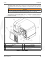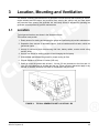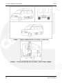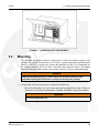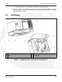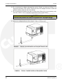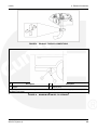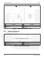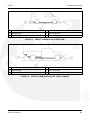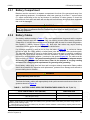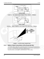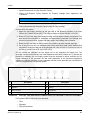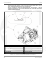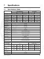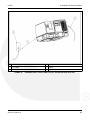
1
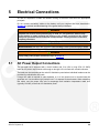
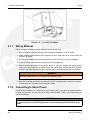
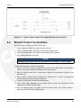
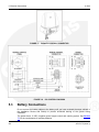
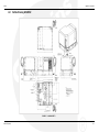
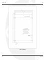
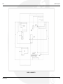
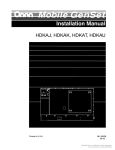
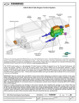
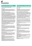
Installation Manual
RV Generator Set
HGJBB (Spec A)
English
Original Instructions
6-2013
A031C172 (Issue 3)
Table of Contents
1. SAFETY PRECAUTIONS ..............................................................................................................
1.1 General Precautions ...............................................................................................................
1.1.1 California - Additional Precautions...............................................................................
1.1.2 Fire Extinguisher - Class Definition..............................................................................
1.1.3 Hazards of Carbon Monoxide ......................................................................................
1.2 Hearing Damage Caused by Noise ........................................................................................
1.3 Generator Voltage is Deadly...................................................................................................
1.4 Battery Gas is Explosive.........................................................................................................
1.5 Moving Parts Can Cause Severe Personal Injury or Death ...................................................
1.6 Engine Exhaust is Deadly.......................................................................................................
1.7 Fuel is Flammable and Explosive ...........................................................................................
1.8 Substances Hazardous to Health ...........................................................................................
1.9 Propane ..................................................................................................................................
1.9.1 Hazardous Reactions...................................................................................................
1.9.2 Protective Measures ....................................................................................................
1.9.3 Storage and Transport .................................................................................................
1.9.4 Emergency Action........................................................................................................
1.10 Petrol (UK)/Gasoline .............................................................................................................
1.10.1 Hazardous Reactions.................................................................................................
1.10.2 Protective Measures ..................................................................................................
1.10.3 Storage and Transport ...............................................................................................
1.10.4 Emergency Action....................................................................................................
1.11 Lubricant Oil........................................................................................................................
1.11.1 Hazardous Reactions...............................................................................................
1.11.2 Protective Measures ................................................................................................
1.11.3 Storage and Transport .............................................................................................
1.11.4 Emergency Action....................................................................................................
1
1
2
3
3
4
4
5
5
5
6
7
7
7
7
8
8
8
9
9
9
10
10
11
11
11
11
2. INTRODUCTION..........................................................................................................................
2.1 About This Manual................................................................................................................
2.2 Installation Codes and Standards for Safety ........................................................................
2.3 Typical Genset ......................................................................................................................
2.4 Electromagnetic Compatibility Compliance...........................................................................
13
13
14
14
16
3. LOCATION, MOUNTING AND VENTILATION ............................................................................
3.1 Location ................................................................................................................................
3.2 Mounting ...............................................................................................................................
3.3 Ventilation .............................................................................................................................
17
17
19
21
4. EXHAUST CONNECTIONS.........................................................................................................
4.1 Tailpipe Installation ...............................................................................................................
4.2 Vehicle Clearances ...............................................................................................................
23
23
26
A031C172 (Issue 3)
i
Table of Contents
6-2013
5. ELECTRICAL CONNECTIONS....................................................................................................
5.1 AC Power Output Connections.............................................................................................
5.1.1 Wiring Methods ..........................................................................................................
5.1.2 Connecting to Shore Power .......................................................................................
5.2 Remote Control Connections................................................................................................
5.3 Battery Connections..............................................................................................................
5.3.1 Battery Compartment .................................................................................................
5.3.2 Battery Cables............................................................................................................
5.3.3 Battery Cable Connections at the Generator Set ......................................................
5.3.4 Generator Set (Equipment) Grounding Screw ...........................................................
29
29
30
30
31
32
33
33
34
35
6. FUEL CONNECTIONS.................................................................................................................
6.1 Gasoline Motorized ...............................................................................................................
6.1.1 Fuel Hoses.................................................................................................................
6.1.2 Fuel Lines...................................................................................................................
6.1.3 Routing Fuel Lines .....................................................................................................
6.2 LPG.......................................................................................................................................
37
37
38
39
39
40
7. SPECIFICATIONS .......................................................................................................................
7.1 Specifications Table..............................................................................................................
43
43
8. INSTALLATION REVIEW AND STARTUP ..................................................................................
8.1 Installation Review ................................................................................................................
8.2 Startup ..................................................................................................................................
8.3 Hot Air Recirculation Test .....................................................................................................
8.4 Test Requirement .................................................................................................................
45
45
45
46
46
APPENDIX A. APPENDIX ................................................................................................................
A.0 Outline Drawing A034N392 ..................................................................................................
49
51
ii
A031C172 (Issue 3)
1
Safety Precautions
Thoroughly read the OPERATOR'S MANUAL before operating the genset. Safe operation
and top performance can only be obtained when equipment is operated and maintained
properly.
The following symbols in this manual alert you to potential hazards to the operator, service
person and equipment.
DANGER
alerts you to an immediate hazard which will result in severe personal injury or death.
WARNING
alerts you to a hazard or unsafe practice which can result in severe personal injury or death.
CAUTION
alerts you to a hazard or unsafe practice which can result in personal injury or equipment
damage.
1.1
General Precautions
WARNING
The generator set produces carbon monoxide, has dangerous moving parts and may be
hot at times. Keep children away from the generator set.
WARNING
Evaporative starting fluids are highly explosive and may cause personal injury or death
if ignited. Do not use evaporative starting fluids.
WARNING
Alcohol, drugs and mental or physical fatigue may cause impairment which may result
in personal injury to the affected person or others. Do not operate, service, or install a
generator set after consuming alcohol or drugs, or when mentally or physically
fatigued.
WARNING
Hot, moving, or electrically charged parts can cause severe injury or death. Only trained
and experienced personnel should make adjustments while the generator set is
running.
WARNING
Operating the genset with the access cover off can result in severe personal injury or equipment
damage. Hot components are exposed when the access cover is removed and genset cooling air
does not circulate properly. Do not operate the genset with the access cover removed.
A031C172 (Issue 3)
1
1. Safety Precautions
6-2013
WARNING
Improper installation may cause product damage, severe injury, or death. Comply with
all applicable local, state and federal codes and regulations to verify proper generator
set installation.
WARNING
When equipped with an integral or add-on Automatic Generator Starting System (AGS)
control, carbon monoxide exhaust inhalation (CO), electric shock, and moving parts
hazards are possible due to unexpected starting. Turn off AGS whenever performing
maintenance or service, when the vehicle is stored between uses, is awaiting service,
or is parked in a garage or other confined area to avoid these hazards.
WARNING
Electricity, fuel, exhaust, moving parts and batteries present hazards which can result
in severe personal injury or death. Read and adhere to all cautions and warnings found
in this manual to avoid personal injury.
CAUTION
Improper battery cable disconnection may cause accidental or remote starting which
may result in injury to the person servicing the generator set. Disconnect the negative
(–) battery cable at the battery to prevent starting while servicing the generator set.
CAUTION
The generator set requires ample air flow to run without overheating. Keep the
generator set and its compartment clean and free from obstructions at all times.
CAUTION
Restricted air flow may cause a fire. Do not store oil, rags or other gear in the generator
set or generator set compartment to prevent starting a fire.
CAUTION
Operation of the generator set may loosen fasteners. Operating a generator set with
loose fasteners may cause damage to the generator set. Make sure all fasteners are
secured and torqued properly.
1.1.1
California - Additional Precautions
WARNING
Benzene and lead in some gasolines have been identified by some state and federal
agencies as causing cancer or reproductive toxicity. Do not ingest, inhale or contact
gasoline or its vapors.
WARNING
Used engine oil has been identified by some state and federal agencies as causing
cancer or reproductive toxicity. Do not ingest, inhale, or contact used oil or its vapors.
2
A031C172 (Issue 3)
6-2013
1.1.2
1. Safety Precautions
Fire Extinguisher - Class Definition
WARNING
A generator set fire can cause property damage, severe personal injury, or death. Keep
multi-class ABC fire extinguishers in a safe, easily accessible location.
TABLE 1.
FIRE EXTINGUISHER CLASS DESCRIPTIONS
Class
1.1.3
Description
A
Involves ordinary combustible materials such as wood and cloth.
B
Involves combustible and flammable liquids and gaseous fuels.
C
Involves live electrical equipment. (ref. NFPA No. 10).
Hazards of Carbon Monoxide
WARNING
Engine-driven generators can produce harmful levels of carbon monoxide causing
nausea, fainting, or death. It is possible to be harmed by this poisonous gas despite
good generator set maintenance and proper ventilation.
1.1.3.1 Only You Can Protect Yourself From CO Poisoning!
• Constantly monitor the area near the generator set exhaust while it is running. Do not allow
people to stand near the generator set exhaust for any period of time.
• Make sure exhaust cannot enter the living quarters through a window, vent or door.
• Make sure all CO detectors or audible alarms are working properly.
• Inspect for exhaust leaks at every startup and after every eight hours of running.
• Make sure there is ample fresh air when operating the generator set in a confined area.
Pay Attention to the Signs of CO Poisioning!
Carbon monoxide poisioning symptoms include:
• headache
• dizziness
• weakness
• nausea
• vomiting
• chest pain
• confusion
• loss of consciousness
A031C172 (Issue 3)
3
1. Safety Precautions
1.2
6-2013
Hearing Damage Caused by Noise
WARNING
Generator sets emit noise. As noise level and time of exposure increases, risk of
hearing damage increases. Select and use personal hearing protection that is
appropriate for the noise level and duration of exposure to generator set noise.
NOTICE
For use in countries where compliance to the EU Noise directive is required - This
generator set has not been evaluated and is not marked for use in open air. Install the
generator set in accordance with the Installation manual. Obey local noise restrictions
when you operate the generator set.
1.3
Generator Voltage is Deadly
WARNING
Improperly connected generator electrical output connections can cause equipment
damage, severe personal injury, or death and therefore must be made by a trained and
experienced electrician in accordance with applicable codes.
WARNING
Improper installations can cause equipment damage, severe personal injury, or death
and therefore all installations must be conducted by a trained and experienced person
in accordance with the installation instructions and all applicable codes.
WARNING
When equipped with an integral or add-on Automatic Generator Starting System (AGS)
control, carbon monoxide exhaust inhalation (CO), electric shock, and moving parts
hazards are possible due to unexpected starting. Turn off AGS whenever performing
maintenance or service, when the vehicle is stored between uses, is awaiting service,
or is parked in a garage or other confined area to avoid these hazards.
WARNING
Back feed to shore power can cause electrocution and damage to equipment. The
generator set must not be connected to shore power or to any other source of electrical
power. An approved switching device must be used to prevent interconnections.
WARNING
Live electrical equipment can cause electricution. Use caution when working on live
electrical equipment. Remove jewelry, make sure clothing and shoes are dry, stand on a
dry wooden platform or rubber insulating mat, and use tools with insulated handles.
4
A031C172 (Issue 3)
6-2013
1.4
1. Safety Precautions
Battery Gas is Explosive
WARNING
Battery gas is highly explosive and may cause personal injury or death if ignited. Take
the proper precautions to avoid personal injury.
• For personal safety, wear appropriate PPE when working on or around the generator set.
• To make sure battery gas is not ignited, do not smoke around the generator set.
• To reduce arcing when disconnecting or reconnecting battery cables, always disconnect
the negative (-) battery cable first and reconnect it last.
1.5
Moving Parts Can Cause Severe Personal Injury or
Death
WARNING
When equipped with an integral or add-on Automatic Generator Starting System (AGS)
control, carbon monoxide exhaust inhalation (CO), electric shock, and moving parts
hazards are possible due to unexpected starting. Turn off AGS whenever performing
maintenance or service, when the vehicle is stored between uses, is awaiting service,
or is parked in a garage or other confined area to avoid these hazards.
WARNING
Moving parts can catch on loose items such as clothing or jewelry. Do not wear loose
clothing or jewelry near moving parts such as PTO (power take-off) shafts, fans, belts,
and pulleys.
WARNING
Moving parts can entangle appendages such as fingers. Keep the protective guards in
place over fans, belts, pulleys, and other moving parts and keep hands away from all
moving parts.
1.6
Engine Exhaust is Deadly
WARNING
When equipped with an integral or add-on Automatic Generator Starting System (AGS)
control, carbon monoxide exhaust inhalation (CO), electric shock, and moving parts
hazards are possible due to unexpected starting. Turn off AGS whenever performing
maintenance or service, when the vehicle is stored between uses, is awaiting service,
or is parked in a garage or other confined area to avoid these hazards.
A031C172 (Issue 3)
5
1. Safety Precautions
6-2013
WARNING
Carbon monoxide is a posionus gas. Inhalation of this gas can cause severe personal
injury or death. Adhere to the following bullet points to make sure carbon monoxide is
not being inhaled by occupants of the vehicle as well as others working on or around
the generator set.
• Inspect for exhaust leaks at every startup and after every eight hours of running.
• Never occupy the vehicle while the generator set is running unless the vehicle is equipped
with a working carbon monoxide detector.
• Never operate the generator set when the vehicle is in a confined space, such as a garage,
basement, or building of any kind.
• Make sure the exhaust system is installed in accordance with the generator set installation
manual.
• Never use engine cooling air for heating a working or living space compartment.
Carbon monoxide poisioning symptoms include:
• headache
• dizziness
• weakness
• nausea
• vomiting
• chest pain
• confusion
• loss of consciousness
1.7
Fuel is Flammable and Explosive
WARNING
Fuel and fuel vapor is highly explosive. Adhere to the following bullets to avoid igniting
fuel and fuel vapors.
• Do not smoke or turn electrical switches on or off where fuel fumes are present or in areas
sharing ventilation with fuel tanks or equipment.
• Keep flame, sparks, pilot lights, arc-producing equipment and all other sources of ignition
well away from fuel lines and sources.
• Fuel lines must be secured, free of leaks and separated or shielded from electrical wiring.
Leaks can lead to explosive accumulations of gas.
• LPG sinks when released and can accumulate inside housings and basements and other
below-grade spaces.
NOTICE
Propane (LPG) is identifiable by the rotten egg smell it emits.
6
A031C172 (Issue 3)
6-2013
1.8
1. Safety Precautions
Substances Hazardous to Health
Generator sets use substances, and emit and create wastes, that can cause health risks.
Generator set operators must use appropriate personal protective equipment (such as clothing,
gloves, protective glasses, goggles, and respiration equipment) when lungs, eyes, or skin are
exposed to fuel, oil, coolant, wet batteries, grease, cleaning agents, or other substances. Use
appropriate containers for transport, storage, and disposal of waste substances. Follow local
regulations for disposal and recycling.
1.9
Propane
This product is also known as C3H8 or liquefied propane gas. It consists of predominantly C3
Hydrocarbons (propane and prepane) with typically < 50 ppm of ethyl mercaptan or other
odorizing agent added to assist leak detection. Contains <0.1% 1, 3 butadeine. Hazardous
components include c3-4 rich, petroleum distillate.
The substance has an initial boiling point of -42.1 ° C flash point of -104° C (PMCC), and a
vapor pressure of 7.5 bar at 15° C.
Keep the container below 50°C. The substance should not be used for any other purpose
without contacting the manufacture or supplier. Installers, operators and maintainers are likely to
encounter this substance. When doubt exists as to correct handling procedure, contact supplier.
1.9.1
Hazardous Reactions
This liquid is extremely flammable (F+). Readily forms an explosive air-vapor mixture at ambient
temps. Avoid smoking, heat sources, such as welding and naked flames, sparks and static
electricity build-up. Thermal decomposition products are hazardous, containing COx compounds.
The vapor is explosive. High vapor concentrations can cause respiratory irritation, dizziness,
nausea, and loss of consciousness. Excessive and prolonged exposure to the mist can cause
chronic inflammatory reaction of the lungs and form of pulmonary fibrosis.
Vapor is heavier than air and may travel to remote sources of ignition. Liquid leaks generate
large volumes of flammable vapor (approx 250:1).
Avoid strong oxidizing agents, e.g. chlorates which may be used in agriculture
Cold burns (frost bite) will result from skin/eye contact with liquid. Toxicity following single
exposure to high level of propane is of low order.
1.9.2
Protective Measures
Ensure good ventilation and avoid heat sources. Observance of good housekeeping rules will
ensure general safety. Do not smoke.
When working on, or testing, injection equipment, special care is required. Use eye protection at
all times.
Adopt a high standard of personal hygiene. In the case of skin contact, flush with water to
normalize temperature. Use gloves and overalls, and eye protection goggles. Use oil impervious
gloves and avoid contamination inside the gloves. If overalls become contaminated, discontinue
use and clean thoroughly. Contaminated clothing should be removed, soaked with water, and
laundered before reuse.
No special respiratory precautions are necessary in normal use.
A031C172 (Issue 3)
7
1. Safety Precautions
1.9.3
6-2013
Storage and Transport
Store and transport only in correctly marked containers. Keep containers closed when not in
use. Keep cool, out of sunlight and away from naked flames. Electrical continuity is required
between the transport and storage vessels during product transfer.
In case of leak clear people away from area to a safe place. DO NOT operate electrical
equipment unless flame proof. Summon emergency services and treat or refer casualties as
necessary.
Extinguish all naked lights AVOID MAKING SPARKS! Try to stop flow of product. Cover drains
and dispense vapor with water spray. Note: Vapor may collect in confined spaces.
1.9.4
Emergency Action
• Fire
Extinguishing media:
Large fire - None. Product flow must be stopped and container cooled by water spray.
Water fog should be used to assist approach to source of the fire.
Small fire - foam/dry powder, CO2
Avoid making sparks. Fire fighters to sue self-contained breathing apparatus. Keep fire
exposed containers cool, using water fog/spray. Prevent run-off from entering waterway,
drains and drinking water supplies. Every precaution must be taken to keep containers
cool to avoid the possibility of a boiling liquid expanding vapor explosion (BLEVE).
• Ingestion: Not applicable
• Inhalation (of vapor)
Remove from further exposure. Obtain medical assistance immediately.
• Eyes
Cold burns should be flushed with water to normalize temperature. Cover burns with sterile
dressings. Do not use ointments or powders. Obtain medical assistance as necessary.
• Skin
Cold burns should be flushed with water to normalize temperature. Cover burns with sterile
dressings. Do not use ointments or powders. Obtain medical assistance as necessary.
• Spillage: See Storage/Transport (Section 5, 7, 3)
1.10
Petrol (UK)/Gasoline
This product is also known as Petrol (UK) or Gasoline. It can be clear liquid with slight tan or
yellow color with a characteristic mild odor. It is a complex combination of hydrocarbons
consisting primarily of paraffins, napthlenes, aromic and olefinic hydrocarbons having carbon
numbers predominantly between C4 and C12.
The substance has an initial boiling point of 25-220°C, a flash point greater than <-40°C, and a
vapor pressure between 0.5 1 bars and has negligible solubility in water.
8
A031C172 (Issue 3)
6-2013
1. Safety Precautions
It is used as a fuel for off-road Petrol powered vehicles and stationary engines, and can be
found in fuel tanks, pipes and injection systems. The substance should not be used for any
other purpose without contacting the manufacture or supplier. Installers, operators and
maintainers are likely to encounter this substance.
1.10.1 Hazardous Reactions
This liquid is extremely flammable. Avoid smoking, heat sources, such as welding and naked
flames, sparks and static electricity build-up. Thermal decomposition products are hazardous,
containing COx, NOx and SOx compounds.
The vapor is explosive. High vapor concentrations can result in central nervous system and
respiratory depression with subsequent loss of consciousness.
Where ventilation is poor or temperatures high, vapor production may be a hazard. Excessive
and prolonged exposure to the mist can cause chronic inflammatory reaction of the lungs and
form of pulmonary fibrosis.
Avoid strong oxidizing agents, e.g. chlorates which may be use in agriculture.
Petrol is slightly irritating to the skin and has a defatting action. Toxicity following single
exposure to high level of Petrol is of low order. Prolonged, repeated skin contact may de-fat the
skin resulting in possible skin irritation and dermatitis. In some cases warty, cancerous growths
have occurred. This product contains benzene (<1%) which is classified as a carcinogen.
Exposure to Benzene may result in blood disorders such as anemia and leukemia. Toxic to
aquatic organisms, may cause long-term adverse effects in aquatic environment.
1.10.2 Protective Measures
Ensure good ventilation and avoid heat sources. Observance of good housekeeping rules will
ensure general safety. Do not smoke. Avoid breathing mist.
When working on, or testing, injection equipment, special care is required to avoid perforation of
skin by high pressure fuel. Use eye protection in the event of suspected high pressure leak.
Adopt a high standard of personal hygiene. In the case of skin contact, wash well with soap and
water.
Use glove and overalls, and eye protection goggles if there is a risk of splashing. Use oil
impervious gloves and avoid contamination inside the gloves. If overalls become contaminated,
discontinue use and clean thoroughly. Contaminated clothing should be removed, soaked with
water, and laundered before use.
No special respiratory precautions are necessary in normal use.
DO NOT use as a solvent for removing dirt/grease etc, from skin.
1.10.3 Storage and Transport
Store and transport only in correctly marked containers. Keep containers closed when not in
use. Keep cool, out of sunlight and away from naked flames. Electrical continuity is required
between the transport and storage vessels during product transfer.
Contain leak/spill with sand, earth or other suitable material, and prevent entry of substance into
drainage/sewerage system, water-courses and land. Dispose of unwanted or absorbed
substance through an authorized contractor to a licensed site.
Inform local and fire authorities should the product reach waterways, drains etc.
A031C172 (Issue 3)
9
1. Safety Precautions
6-2013
1.10.4 Emergency Action
• Fire Extinguishing media:
Large fire - Foam/water fog. Never use water jet.
Small fire - foam/dry powder, AAAF,CO2, sand, earth.
Avoid making sparks. Fire fighters to use self-contained breathing apparatus. Keep fire
exposed containers cool, using water fog/spray. Prevent run-off from entering waterway,
drains and drinking water supplies.
• Ingestion
Do not induce vomiting. Wash the mouth out with water, and send to hospital immediately.
• Inhalation (of vapor)
Remove from further exposure. Obtain medical assistance immediately.
• Aspiration (inhalation of liquid)
If, following ingestion of gas oil, vomiting occurs, there is danger of aspiration into the
lungs. This would cause intense local irritation and chemical pneumonitis that can be fatal.
Obtain immediate medical assistance.
• Eyes
Irrigate copiously with water or preferably eyewash solution for at least five minutes. If
irritation persists seek medical advice.
• Skin
Wash thoroughly with soap and water. Change clothing if necessary.
If high pressure injection has occurred prompt surgical attention is required.
• Spillage
Absorb using sand, earth or other suitable material. Dispose of unwanted or absorbed
flammable material as directed under Storage/ Transport (Section 5.7.3). In the event of a
major spillage, only trained personnel wearing self contained breathing apparatus should
handle the spill. Any spillage or leak should be treated as a major fire/explosion hazard. If
vehicles present, switch off engines.
1.11
Lubricant Oil
Also known as oil, lube oil, sump oil. New oil is a viscous liquid with a slight characteristic odor.
The base oil contains distillates (petroleum) and solvent-dewaxed heavy paraffinic. It is not
classified as dangerous according to Directive 1999/45/EC and its amendments, and is not
classified according to the EU regulations.
It has a boiling point greater than 150° C (302 °F), and a flash point Open Cup of 220° C (438
°F) (Cleveland) and is insoluble in cold water.
It is used in engine lubricant oil systems, sump pan and filters, make-up tanks, and piping
systems as a lubrication oil for use in a wide range of engines operating under severe
conditions. Installers, operators, and maintainers are likely to encounter this product.
10
A031C172 (Issue 3)
6-2013
1. Safety Precautions
1.11.1 Hazardous Reactions
This product is stable, although slightly re-active, with oxidizing agents. Results of
decomposition are carbon oxides (CO, CO2) and water.
Although harmful if ingested (swallowed) or aspirated (breathed in), repeated or prolonged
exposure is not known to aggravate medical conditions.
Used oil may contain harmful combustion by-products and un-burnt fuel that will cause skin
reactions as detailed for fuel. Particular care must be taken if oil from a severely overheated
engine is handled. Use impervious gloves, lab coat, and safety glasses. Do not breathe vapor or
spray.
1.11.2 Protective Measures
Ensure good ventilation and avoid heat sources.
Adopt a high standard of personal hygiene. In case of skin contact, wash thoroughly with soap
and water.
Use safety glasses, impervious gloves, and lab coat. Avoid contamination inside the gloves. If
overalls become contaminated, discontinue use and clean thoroughly.
No special respiratory precautions are necessary in normal use. Do not breathe vapor or spray
when handling hot materials.
1.11.3 Storage and Transport
Store and transport only in correctly marked containers. Keep containers tightly sealed when not
in use. Keep in cool, well ventilated area, out of sunlight and away from naked flames. Store
well away from food-stuffs and drinking water.
Wear splash goggles, full suit, boots, and gloves. Absorb leaks or spills with an inert material
and dispose of unwanted or absorbed substance through an authorized contractor to a licensed
site. Finish cleaning by spreading water on the contaminated surface and allow to evacuate
through the sanitary system.
1.11.4 Emergency Action
• Fire - Fire-fighters are to use self contained breathing apparatus and full turnout gear.
Keep fire-exposed containers cool.
• Extinguishing media for large fire: Use water spray, fog or foam. Do not use water jet.
• Extinguishing media for small fire: Use dry chemical powder or CO2.
• Ingestion - Do not induce vomiting. Obtain medical advice immediately.
• Inhalation (of vapor) - Remove from further exposure. Obtain medical attention.
• Aspiration (inhalation of liquid) - Obtain immediate medical assistance.
• Eyes - Flush copiously with water or preferably eye-wash solution for at least fifteen
minutes. Obtain medical advice.
• Skin - Wash thoroughly with soap and water. Obtain medical advice if irritation develops.
Change clothing if necessary and wash before re-use.
• Spillage - Absorb with an inert material and dispose of as directed under Storage and
Transport.
A031C172 (Issue 3)
11
1. Safety Precautions
6-2013
This page is intentionally blank.
12
A031C172 (Issue 3)
2
Introduction
WARNING
Improperly connected generator electrical output connections can cause equipment
damage, severe personal injury, or death and therefore must be made by a trained and
experienced electrician in accordance with the installation instructions and all
applicable codes .
WARNING
Improper installations can cause equipment damage, severe personal injury, or death
and therefore all installations must be conducted by a trained and experienced person
in accordance with the installation instructions and all applicable codes.
2.1
About This Manual
This manual is a guide for the installation of the generator set model(s) identified on the cover of
this manual. Proper installation is essential for safe, reliable and quiet operation. Read through
this manual before starting the installation. Keep this manual and the Operator Manual with the
rest of the vehicle documentation.
WARNING
Improper installation can result in severe personal injury, death and equipment damage.
The installer must be qualified to perform the installation of electrical and mechanical
equipment.
WARNING
This generator set is not a life support system. It can stop without warning. Children, persons
with physical or mental limitations, and pets could suffer personal injury or death. A personal
attendant, redundant power or an alarm system must be used if generator set operation is
critical.
WARNING
This generator set is not ignition protected and shall not be used in a flammable vapor
environment.
CAUTION
Unauthorized modifications or replacement of fuel, exhaust, air intake or speed control
system components that affect engine emissions are prohibited by law in the State of
California.
See the Operator Manual for operation and maintenance and the Service Manual for service.
NOTICE
Manuals are updated from time-to-time to reflect changes in the equipment and its
specifications. For this reason, only the copy of the installation manual supplied with
the generator set should be used as a guide for installation.
A031C172 (Issue 3)
13
2. Introduction
2.2
6-2013
Installation Codes and Standards for Safety
CAUTION
The Commercial Genset Warranty applies only when the genset is installed in a Commercial or
Recreational Vehicle. The RV Genset Warranty applies only when the genset is installed in a
Recreational Vehicle.
The installer bears sole responsibility for the selection of the appropriate genset, for its proper
installation and for obtaining approvals from the authorities (if any) having jurisdiction over the
installation. These sets meet the basic requirements of the Standard for Safety for Engine
Generator Sets for Recreational Vehicles, ANSI/RVIA EGS-1.
The order of precedence of documentation to adhere to when installing is as follows:
1. Cummins Onan Installation Manual
2. ANSI 1192 NFPA No. 501C
Federal, State and local codes, such as the California Administrative Code—Title 25 (RV
installation), might also be applicable. Installation codes and recommendations can change from
time-to-time and are different in different countries, states and municipalities. Obtain the
standards in Table 2 for reference.
TABLE 2.
REFERENCE CODES AND STANDARDS
Code of Federal
Regulations, Title
49: Chapter III
and Chapter V
Superintendent of Documents P. O. Box 371954 Pittsburgh, PA 15250-7954
NFPA No 70,
1192
National Fire Protection Association 470 Atlantic Avenue Boston, MA 02210
NFPA No 501C
(ANSI A1192)
National Fire Protection Association 470 Atlantic Avenue Boston, MA 02210
ANSI/RVIA-EGS1
ANSI A1192
(NFPA No 501C)
Recreational Vehicle Industry Association 14650 Lee Road Chantily, VA 22021
California
Administrative
Code—Title 25,
Chapter 3
State of California Documents Section P.O. Box 1015 North Highlands, CA 95660
CAN/CSA-Z240
Recreational
Vehicles Bulletin
946
Canadian Standards Association Housing and Construction Materials Section 178 Rexdale Blvd.
Rexdale, Ontario, Canada M9W 1R3
2.3
Typical Genset
The control panel and the components requiring attention during periodic maintenance (see
Periodic Maintenance) are located behind a removable access cover. See Figure 2.
Removing the access cover: Unlock the access cover, using a flat-end tool. Pull the access
cover down and out to remove the access cover.
14
A031C172 (Issue 3)
6-2013
2. Introduction
Securing the access cover: Slide the access cover up and into the opening in the housing.
Hold the base of the cover flush with the housing. Use a flat-end tool to secure the access
cover.
WARNING
Operating the genset with the access cover off can result in severe personal injury or equipment
damage. Hot components are exposed when the access cover is removed and genset cooling air
does not circulate properly. Do not operate the genset with the access cover removed.
The genset itself is usually located behind a door in a compartment somewhere around the
perimeter of the vehicle.
No.
Description
No.
Description
1
Removable Access Cover
5
Control Panel and Circuit Breaker
2
Muffler (inside cover)
6
Fuel Filter (gasoline models only)
3
Air Filter Cover
7
Oil Fill Cap and Dipstick
4
Oil Drain (bottom)
8
Spark Plug Access
FIGURE 1.
A031C172 (Issue 3)
TYPICAL GENSET
15
2. Introduction
2.4
6-2013
Electromagnetic Compatibility Compliance
Generator sets emit and receive electromagnetic (radio frequency) energy. If the generator set
affects operation of nearby devices, or nearby devices affect generator set operation, increase
the distance between them.
When used in countries where compliance to the EMC directive is required: This generator set
has been evaluated for use in the residential, commercial, and light industrial environments.
16
A031C172 (Issue 3)
3
Location, Mounting and Ventilation
The location, mounting and enclosure of a generator set must be such that mounting is secure,
engine exhaust and fuel vapors are prevented from entering the vehicle, rain and road debris
are prevented from entering the generator set, and ready access is afforded for operating the
generator set and performing periodic maintenance.
3.1
Location
Typical genset locations are shown in the illustratioin below.
The location must provide:
1. Ready access for starting and stopping the genset and performing all periodic maintenance
2. Separation from sources of flammable vapors, such as batteries and fuel tanks, which the
genset can ignite
3. Access for connecting and disconnecting fuel lines, battery cables, remote control wiring
and AC wiring
4. Access from below for draining engine oil and changing the fuel pump
5. Unobstructed space below the genset for proper cooling air flow.
6. Ground clearance of at least 12 inches (305 mm).
7. Space to mount the genset with at least 1 1/4 inch (32 mm) clearance to the front and 1/4
inch (6.5 mm) clearance on all sides and the top. These minimum clearances apply to any
thermal or acoustic insulation with which a compartment may be lined.
FIGURE 2.
A031C172 (Issue 3)
TYPICAL GENERATOR SET LOCATIONS - RV
17
3. Location, Mounting and Ventilation
FIGURE 3.
FIGURE 4.
18
6-2013
TYPICAL GENERATOR SET LOCATIONS - CLASS B VAN
TYPICAL GENERATOR SET LOCATIONS - PICKUP TRUCK CAMPER
A031C172 (Issue 3)
6-2013
3. Location, Mounting and Ventilation
FIGURE 5.
3.2
GENERATOR SET COMPARTMENT
Mounting
1. The generator set support structure must be able to resist the dynamic weight of the
generator set: cyclical vertical forces of ± 375 lbs (± 3 gravity units) and cyclical horizontal
forces of ± 125 lbs (± 1 gravity unit). Secure the generator set with 3 or 4 (depending on
the mounting method) 3/8-16 NC bolts. The bolts must protrude at least 1-1/2 threads
beyond the base pan weld nuts but not more than 1/2 inch (13 mm), to avoid interference.
WARNING
The generator set can fall from the vehicle if the supporting structure is weak and
cause severe personal injury or death. Design the structure carefully, follow
applicable mounting kit instructions and torque mounting bolts properly.
2. The generator set can be mounted on or below the vehicle floor:
• Below-Floor Mounting: Use one of the mounting kits available from Onan. Follow the
instructions in the kit and use Underfloor Template A034N392 to locate the assembly.
WARNING
Fire is deadly! Install a fire-resistive barrier of approved materials between the
floor and the generator set.
A031C172 (Issue 3)
19
3. Location, Mounting and Ventilation
6-2013
• A plywood or particle board floor must be reinforced with steel to resist the dynamic
weight of the generator set. Do not mount the generator set within the approach or
departure angels of the vehicle or below the axle line. If the floor is of combustible
material such as wood, install a barrier of 26 gauge galvanized steel or equivalent
between the floor and the generator set (See ANSI A1192).
• Above-Floor Mounting: Construct a vapor-tight, fire-resistant compartment of 26
gauge galvanized steel or equivalent to isolate the generator set from the vehicle
interior. Do not duct generator set cooling air, which can include exhaust gases, into
the vehicle for heating.
WARNING
Exhaust gas and fire are deadly! Install a vapor-tight and fire-resistant barrier
of approved materials between the generator set and the vehicle interior. Do
not duct generator set cooling air into the vehicle for heating.
3. Locate or shield the generator set cooling air openings from direct rain, road splash and
debris thrown up by the road wheels.
4. Provide ready access for fuel and battery connections and all periodic maintenance
procedures. When mounting the generator set on a floor, use Compartment Template
A034N392 to locate the cutout for the oil drain. Do not route the exhaust tailpipe
underneath the oil drain.
WARNING
A hot exhaust tailpipe can ignite oil drain spills causing severe personal injury or
death. Do not route the exhaust tailpipe underneath the oil drain.
5. The generator set must not share a compartment or ventilation with batteries or fuel tanks.
An operating generator set can ignite flammable vapors.
6. Generator set cooling air must not be obstructed.
• Generally, the effect of natural convection in ventilating flammable vapors and engine
heat after shutdown is better the higher the compartment air inlet. This should be
especially noted when fuel vapor lock is an issue.
• A free-air inlet size of at least 36 in2 (232 cm2) is required. Grilles, louvers and other
kinds of decorative treatments for air openings are restrictive. Contact the
manufacturer of the decorative assembly or material to find out how large of an
opening is required to obtain the minimum free-air inlet size.
• When mounting the generator set on a floor, use Compartment Template A034N392
to locate the cutout for the cooling air outlet. The floor must not block off any portion
of the generator set cooling air outlet or cause recirculation of hot air back into the
generator set inlet.
• Make sure the space below the generator set cooling outlet is unobstructed for at
least 12 inches (305 mm) and open on at least three sides.
7. See the appropriate outline drawing for the minimum inside dimensions of a generator set
compartment. If the compartment has acoustic insulation, increase the minimum
compartment dimensions by the thickness of the insulation panels. The following minimum
clearances are required between the generator set and the compartment or it's insulation.
• At least 1 1/4 inch (32 mm) clearance is required on the front.
20
A031C172 (Issue 3)
6-2013
3. Location, Mounting and Ventilation
• At least 1/4 inch (6.5 mm) clearance is required on the sides and top.
8. Acoustic insulation and adhesive should be classified as "Self-Extinguishing" at not less
than 200 °F (90 °C). Do not line the bottom of the compartment with insulation - insulation
absorbs spilled fuel and oil.
3.3
Ventilation
No.
Description
No.
Description
1
Air inlet
3
Air outlet vent
2
Air outlet
4
LP regulator vent
FIGURE 6.
A031C172 (Issue 3)
GENERATOR SET COOLING AIR INLET AND OUTLET
21
3. Location, Mounting and Ventilation
6-2013
This page is intentionally blank.
22
A031C172 (Issue 3)
4
Exhaust Connections
The generator set is equipped with a U.S. Forest Service approved spark-arrest muffler. Failure
to provide and maintain a spark arrestor can be a violation of the law. Liability for damage,
injury, and warranty expense due to the modification of the exhaust system or the use of
unapproved parts is the responsibility of the person performing the modification or installing the
unapproved exhaust system parts.
WARNING
EXHAUST GAS IS DEADLY! To keep exhaust gases from entering the vehicle do not terminate
the exhaust tailpipe underneath the vehicle or closer than 153mm (6 in) to openings into the
vehicle or route it such that it is not protected. Use approved materials only.
The tailpipe of the generator set will be hot during operation and can cause severe burns. To
reduce the risk of contact, concentration must be used where the tailpipe will be located and
routed.
The generator set exhaust system must be gas tight and designed to prevent entry of exhaust
gasses into the vehicle interior.
4.1
Tailpipe Installation
The muffler is mounted inside the generator set and has a flange to which the tailpipe adapter
(available from Cummins Onan) is bolted or a collar to which the tailpipe is clamped or a short
adapter bolted to its oulet flange.
WARNING
Flexible pipe is not gas tight or durable and can cause exhaust gas leaks. Do not use
flexible pipe for tailpipe.
1. Use 18-gauge 1-1/8 inch I.D. aluminized steel tubing or material of equivalent heat and
corrosion resistance for the tailpipe.
2. Support a tailpipe longer than 457mm (1-1/2 ft) near its end and at intervals of 900mm (3
ft) or less. Use automotive-type tailpipe hangers. Do not attach the hangers to combustible
material such as wood.
3. Use U-bolt muffler clamps to connect sections of tailpipe. Overlapping pipe should be
slotted.
4. Do not route the tailpipe near fuel lines or fuel tanks.
5. Do not route the tailpipe closer than 76mm (3 in) to combustible material (wood, felt,
cotton, organic fibers, etc.) unless it is insulated or shielded. The temperature rise (above
ambient) on adjacent combustible material must not exceed 65 °C (117 °F).
6. Do not route the exhaust tailpipe underneath the oil drain.
7. Do not route the exhaust tailpaipe such that is will restrict the air inlet/outlet.
8. To keep the tailpipe from being damaged, do not route it such that it protrudes into the
approach or departure angles of the vehicle or below the axle clearance line.
9. Do not interconnect generator set and vehicle engine exhaust systems.
A031C172 (Issue 3)
23
4. Exhaust Connections
6-2013
10. Do not terminate the tailpipe underneath the vehicle. Extend it a minimum of 25mm (1 in)
beyond the perimeter of the vehicle. Support the end of the tailpipe such that it cannot be
pushed in and up under the skirt of the vehicle.
11. Do not terminate the tailpipe such that it is closer than 153mm (6 in) to any opening, such
as a door, window, vent, or unsealed compartment into the vehicle interior.
CAUTION
Excessive back pressure can cause loss of performance and engine damage.
12. Make sure a tailpipe deflector will not cause excessive back pressure.
FIGURE 7.
FIGURE 8.
TYPICAL TAILPIPE INSTALLATION (BOTTOM OF UNIT)
24
TYPICAL TAILPIPE INSTALLATION (SIDE OF UNIT)
A031C172 (Issue 3)
6-2013
4. Exhaust Connections
FIGURE 9.
No.
1
Description
Tailpipe
EXHAUST TAILPIPE CONNECTIONS
No.
2
Description
153mm (6 in)
No opening into the vehicle interior may be closer than 153mm (6 in) to the end of the tail pipe (within area 2,
identified in this image).
FIGURE 10.
A031C172 (Issue 3)
MINIMUM DISTANCES TO OPENINGS
25
4. Exhaust Connections
No.
6-2013
Description
No.
Description
A
Side view
1
25mm (1 inch)
B
Straight-on view
2
The last tailpipe hanger must be as close to the end
as possible.
FIGURE 11.
TERMINATING THE EXHAUST TAILPIPE
4.2
Vehicle Clearances
No.
Description
1
Approach angle
2
Departure angle
3
FIGURE 12.
26
No.
Description
Axle clearance line
VEHICLE CLEARANCES (RV)
A031C172 (Issue 3)
6-2013
4. Exhaust Connections
No.
Description
1
Approach angle
2
Departure angle
3
FIGURE 13.
No.
Description
1
Approach angle
2
Departure angle
FIGURE 14.
A031C172 (Issue 3)
No.
Description
Axle clearance line
VEHICLE CLEARANCES (CLASS B VAN)
No.
3
Description
Axle clearance line
VEHICLE CLEARANCES (PICKUP TRUCK CAMPER)
27
4. Exhaust Connections
6-2013
This page is intentionally blank.
28
A031C172 (Issue 3)
5
Electrical Connections
AC and DC separation of cable are needed. Routing of the wires must follow the appropriate
principals.
Do not connect the battery cables to the battery until you complete the steps described in
Chapter 8 to prevent accidental starting of the genset during installation.
WARNING
HAZARDOUS VOLTAGE! Touching uninsulated live parts inside the generator set and connected
equipment can result in severe personal injury or death. For your protection, stand on a dry
wooden platform or rubber insulating mat, make sure your clothing, and shoes are dry, remove
jewelry from your hands and use tools with insulated handles. Secure protective covers when
completing installation.
WARNING
IMPROPER WIRING can cause fire or electric shock resulting in severe personal injury or death.
WARNING
Accidental starting of the genset can cause severe personal injury or death. Do not connect the
starting battery until you have reviewed the steps in Chapter 8.
5.1
AC Power Output Connections
The generator set is equipped with a circuit breaker and 3.1m (124 in) long 25-A (12 AWG)
leads for AC power output which exit through a rain-tight 1/2 inch trade size conduit connector.
The leads can be terminated at the main AC distribution panel where individual breakers can be
provided for vehicle/trailer AC loads.
If longer AC cable is required or code stipulates, a 4 x 4 inch junction box is mounted near the
generator set. Use a weather type junction box if it is exposed to the elements. When extending
this cable, use the proper size wire for amperage and insulation temperature rated wire
(typically 12 AWG) to the main AC distribution panel.
A031C172 (Issue 3)
29
5. Electrical Connections
6-2013
FIGURE 15.
5.1.1
AC OUTPUT CONDUIT
Wiring Methods
Follow the National Electrical Code, especially noting the following:
1. Have a qualified electrician supervise and inspect the installation of all AC wiring.
2. Install vibration-proof switches and controls that won't open and close circuits when the
vehicle is in motion.
3. Provide ground fault circuit interrupters (GFCIs) for all convenience power receptacles.
4. Route AC wiring, remote control wiring, and fuel lines separately.
5. Seal all conduit openings into the vehicle interior to keep out exhaust gas. Apply silicone
rubber or an equivalent type of sealant inside and outside each conduit connector. (Flexible
conduit is not vapor tight and will allow exhaust gas to enter along the wires if not sealed.)
WARNING
Faulty grounding can lead to fire and electrocution, resulting in severe personal injury or
death. Grounding must be in accordance with applicable codes.
6. Bond the generator set and all connected AC and DC equipment and controls to a common
grounding point in accordance with applicable codes.
5.1.2
Connecting to Shore Power
A vehicle with provisions for connecting to shore power (utility) must have an approved device
to keep the generator set and utility from being interconnected. Refer to the image below for
typical connections.
WARNING
Backfeed to shore power (utility) can cause electrocution or damage to equipment. Use
an approved device to prevent the generator set from being interconnected with shore
power.
30
A031C172 (Issue 3)
6-2013
5. Electrical Connections
FIGURE 16.
5.2
TYPICAL CONNECTIONS WITH TRANSFER SWITCH AND UTILITY
Remote Control Connections
Onan offers three varieties of remote control panel:
• Remote start/stop switch with status indicator light only.
• Remote start/stop switch with status indicator light and hour meter.
• Remote start/stop switch with status indicator light and DC voltmeter.
• 8-pin mating connector with pigtail.
NOTICE
Separately sold remote control wiring harnesses are available in several lengths.
To make connections to a remote control panel:
1. Refer to the following figure to fabricate the remote control panel and/or wiring harness
when not using the accessories available from Cummins Onan.
2. Mark the remote control end of each lead to identify the connector pin number at the
generator set.
3. Use insulated 18 AWG copper conductors for distances up to 30 feet (9 meters) and
heavier gauge conductors for greater distances.
4. Protect the wiring with full-length flexible sheathing.
5. Route control leads separately from AC power leads to reduce the possibility of erratic
operation due to false induced signals.
6. Seal the opening where the leads enter the vehicle interior with silicone rubber or
equivalent sealant to keep out exhaust gas.
A031C172 (Issue 3)
31
5. Electrical Connections
6-2013
FIGURE 17.
REMOTE CONTROL CONNECTOR
FIGURE 18.
5.3
DC CONTROL DIAGRAM
Battery Connections
Do not connect the battery cables to the battery until you have reviewed the steps outlined in
the Installation Review and Startup to prevent accidental starting of the genset during
installation.
The genset has a 12 VDC, negative-ground engine control and cranking system. See Section
7.1 for the requirements for cranking batteries.
32
A031C172 (Issue 3)
6-2013
5.3.1
5. Electrical Connections
Battery Compartment
Batteries must be mounted in a separate compartment from that of the genset and away from
spark-producing equipment. A compartment must have openings of at least 1.7 square inches
(11 square centimetres) at the top and bottom for ventilation of battery gasses. It should be
mounted such that spills and leaks will not drip acid on fuel lines, wiring and other equipment
that could be damaged.
WARNING
Arcing can ignite the explosive hydrogen gas given off by the battery, causing severe personal
injury. The battery compartment must be ventilated and must isolate the battery from sparkproducing equipment.
5.3.2
Battery Cables
Size battery cables according to Table 3. The current path between the genset and the negative
(-) battery terminal must also be able to carry full cranking current without causing excessive
voltage drop. It is highly recommended that a full-length cable be used to connect the genset to
the negative (-) battery terminal (Figure 19). Note also that codes may require bonding
conductors from the genset and the battery to the vehicle frame.
If a full-length negative (-) cable is not run from the battery (Figure 20), a continuous chassis
rail can be used. No rivited, welded, or bolted frame joints are allowed in this conductors path.
The electrical resistance of riveted or bolted frame joints must also be carefully considered,
especially if the joints will be exposed to corrosive conditions. A cable must be used to connect
the frame to the designated negative (-) terminal on the genset (Figure 20). The cable must be
sized according to Table 3. The genset mounting bolts are not considered adequate means
for bonding the genset to the vehicle frame, either for the purpose of carrying cranking
currents or for complying with requirements for genset/system grounding.
Route battery cables away from fuel lines and hot engine exhaust components. Battery cables
should be accessible for inspection and replacement, protected from damage and secured to
prevent chafing due to vibration.
WARNING
Routing battery cables with fuel lines can lead to fire and severe personal injury or death. Keep
battery cables away from fuel lines.
Terminate the battery cables with appropriately sized eyelet connectors and connect them to the
genset as shown in Figure 21.
TABLE 3.
BATTERY CABLE SIZES FOR TEMPERATURES DOWN TO -20° F (-29° C)
TOTAL CABLE LENGTH* FEET (METERS)
CABLE SIZE AWG
0 to 45 (0 to 13.7)
2**
46 to 60 (14 to 18.3)
0
61 to 80 (18.6 to 24.4)
00
* - Battery cable lengths are total lengths from battery to the generator back to the battery and when using a total of
1000CCA (Cold Cranking Amps).
** - A total length of up to 20 feet (6 meters) may be used in warmer climates or when battery capacity totals at least
1000 CCA (Cold Cranking Amps).
A031C172 (Issue 3)
33
5. Electrical Connections
6-2013
FIGURE 19.
FIGURE 20.
FULL-LENGTH CABLE FROM BATTERY NEGATIVE (-) TERMINAL
VEHICLE FRAME AS PATH FROM BATTERY NEGATIVE (-) TERMINAL
FIGURE 21.
5.3.3
BATTERY CABLE CONNECTIONS
Battery Cable Connections at the Generator Set
Terminate the battery cables with ring terminals sized for 5/16 inch nuts and connect them to
the generator set terminal block. Secure the insulating boot on the positive (+) terminal and tie it
to the battery cable with the tie-wrap in the bag with the manuals.
Torque the positive (+) and negative (-) cable terminals to 7.5 lb-ft (10 Nm).
34
A031C172 (Issue 3)
6-2013
5.3.4
5. Electrical Connections
Generator Set (Equipment) Grounding Screw
When required, connect the generator set grounding screw to the vehicle frame with a No. 8
AWG or larger stranded cable having a ring terminal sized for a 3/8 inch screw.
Torque the grounding screw to 8 lb-ft (11 N-m).
A031C172 (Issue 3)
35
5. Electrical Connections
6-2013
This page is intentionally blank.
36
A031C172 (Issue 3)
6
Fuel Connections
See the Operator Manual for recommended fuels and Chapter 7 on page 43 for fuel
consumption.
CAUTION
Unauthorized modifications or replacement of fuel, exhaust, air intake, or speed control system
components that affect engine emissions are prohibited by law in California.
6.1
Gasoline Motorized
The maximum fuel pump lift is 914mm (36 in).
The generator set and propulsion engine fuel supply and return lines must not be
interconnected.
Connections meet the requirements of the following SAE standards, when applicable:
• J1231 (Fromed Tube Ends for Hose Connections and Hose Fittings)
• J1508 (Hose Clamp Spectifications)
• J2260 (Nonmetallic Fuel System Tubing with One or More Layers)
• J2044 (Quick Connector Specification for Liquid Fuel and Vapor/Emissions Systems)
Terminate the generator set fuel pickup above the vehicle engine pickup in the supply tank to
keep the generator set from running the vehicle out of fuel.
Connect 1/4 inch fuel line from the vehicle fuel tank to the generator set.
A031C172 (Issue 3)
37
6. Fuel Connections
No.
6-2013
Description
No.
Description
1
Fuel Hose
4
1/4 inch Fuel Supply Hose Fitting and Fuel Filter
2
Hose Clamp
5
Type 1 Hose Beads
3
Barb Fitting
6
Hose Clamp and Type 3 Hose Bead
FIGURE 22.
6.1.1
GASOLINE MOTORIZED FUEL CONNECTION
Fuel Hoses
The fuel hoses used inside the generator set are low permeation fuel hoses which meet Federal
50 state standards for gasoline evaporative emissions. Low permeation fuel hose is required to
meet the requirements for gasoline generator sets sold in or used for commerce in all 50 states.
The following hose materials are acceptable:
• Avon Automotive “Greenbar" (EO# G-05-018) SAE J30R7
• Avon Automotive “Greenbar 1200" (EO# C-U-05-009) SAE J30R12
• Gates 4219D (EO# C-U-06-002) SAE J30R9
• Gates Barricade (EO# Q-09-019)
• Kubota (EO# C-U-05-003) SAE J30R7
• Mark IV Automotive “Gen2" (EO# C-U-05-002) SAE J30R7
• Mark IV Automotive "Fluoroperm" (EO# C-U-07-017) SAE J30R9
• Mark IV Automotive Dayperm" (EO# C-U-06-030) SAE J30R7
• Mark IV Automotive "Dayperm" (EO# G-05-016)
• Mold-Ex Division of SETi, Inc. "SETiFLEX II" (EO# G-05-17A) SAE J30R7
• Parker Hannifin Corp "Super Flex FL-7 series 389XX" (EO# Q-08-013)
• Veyance Technologies Inc. "Goodyear Flexshield" (EO# Q-09-022)
38
A031C172 (Issue 3)
6-2013
6. Fuel Connections
CAUTION
Lubricants used when connecting fuel hoses can leave residues that can clog fuel jets. Only use
soap-free lubricants such as WD40 which runs through with the fuel without leaving residues
that can clog fuel jets.
6.1.2
Fuel Lines
Tubing:
• Use 1/4 inch I.D. (± 0.003 inch) welded and drawn Type 304L stainless or AISI 1008-1010
low carbon steel tubing of 0.028 inch minimum wall thickness.
• Tubing must meet requirements for 150 psi operating pressure (Ref. ASTM A 539-99) and
have corrosion resistance equal to or better than hot-dipped zinc galvinized.
Hose Beads:
• Use suitable tooling to form tubing ends into SAE J1231 Type 1 or Type 3 double-flare
hose beads.
• Recommended for all tubing and fittings.
Flexible Hose: Use 1/4 inch I.D. fuel hose that meets applicable standards for evaporative
emissions.
6.1.3
Routing Fuel Lines
WARNING
Electric arcs can ignite gasoline leading to severe personal injury or death. Do not run
wiring and fuel lines together.
1. Route the fuel line along bulkheads and frame members such that it is protected. The
entire length of the fuel line must be visible for inspection and accessible for replacement.
It is preferred that fuel line routing be parallel to the motorized chassis fuel line.
FIGURE 23.
FUEL LINE PREFERRED ROUTING
NOTICE
The fuel line should be at or above the top of the fuel tank to reduce siphoning if a
line breaks or a hose comes off.
2. Support fuel lines to restrain movement and prevent chaffing or contact with sharp edges,
electrical wiring, and hot exhaust parts.
A031C172 (Issue 3)
39
6. Fuel Connections
6.2
6-2013
LPG
WARNING
LPG is flammable and explosive and can cause asphyxiation. NFPA 58, Section 1.6
requires all persons handling LPG to be trained in proper handling and operating
procedures.
WARNING
High LPG supply pressure can cause gas leaks which can lead to fire and severe personal injury
or death. LPG supply pressure must be adjusted to Specifications by trained and experienced
personnel.
WARNING
Sparks can ignite LPG, leading to severe personal injury or death. Do not run electrical
wiring and fuel lines together. Separate them with conduit or tubing if run through the
same opening. Do not tie them together.
WARNING
LPG leaks from the vent hose can lead to explosive accumulations inside the generator
set compartment. Route the LPG vent hose so that it vents to the outside or provide
required openings.
WARNING
The flameout of an unvented LPG appliance can lead to explosive accumulations of gas
inside the vehicle and the danger of severe personal injury or death. Do not connect the
generator set fuel supply line to any vehicle appliance supply line.
WARNING
Testing for gas leaks with a flame can cause a fire or explosion that could lead to
severe personal injury or death. use approved methods only.
NFPA 58, the Standard for the Storage and Handling of Liquified Petroleum Gases (NFPA 58)
should be used as a guide for the installation of the LPG fuel system.
NFPA 1192, the Standard on Recreation Vehicles for Liquified Petroleum Gases should be used
as a guide for the installation of the LPG fuel system in regard to the following sections:
• Propane Container
• Propane Suppy Connection/Connector
• Regulated High Pressure Piping
• Propane Systems
• Propane Piping Systems
• Propane Piping Design
• Propane Pipe Sizing
NOTICE
Generator is included in pipe sizing calculations and testing.
40
A031C172 (Issue 3)
6-2013
6. Fuel Connections
• Special Requirement for High Pressure Testing
• Testing Low-Pressure Piping Systems for Propane Leakage After Appliances are
Connected
NOTICE
Generator is considered connected as an appliance for testing.
• Testing Regulated High-Pressure Piping System for Gas Leakage
Connect LPG fuel system:
1. Adjust the gas supply pressure (at the gas inlet of the pressure regulator) to at least
229mm (9 in) Water Column (WC). The pressure must not exceed 330mm (13 in) WC.
2. Route LPG fuel lines away from electrical wiring and hot engine exhaust components. Fuel
lines should be accessible for inspection and replacement, protected from damage, and
secured to prevent kinking, contact with sharp edges, and chafing due to vibration.
3. Route the LPG vent hose so that it vents to the outside or provide required openings.
4. For a long fuel line run, use seamless steel tubing with flared ends. Make flexible hose
connections at the fuel tank and at the generator set. Use 3/8 inch I.D. fuel line for runs up
to 0.9m (3 ft) and 1/2 inch I.D. up to 4.6m (15 ft).
Do not connect the generator set fuel supply line to any appliance fuel supply line. The
generator set can draw fuel away from other appliances and cause a flame out. To prevent the
possibility of flameout, the fuel supply system must be designed to deliver sufficient fuel for
normal operation of the generator set and other appliances at the expected temperature
conditions. It may be necessary to use a separate fuel tank for the generator set if sufficient fuel
cannot be supplied with a single tank system.
No.
Description
No.
Description
1
LPG Fuel Tank
5
Stove
2
Regulator
6
Heating
3
Main Fuel Line
7
Refrigerator
4
Generator Set
FIGURE 24.
LPG FUEL LINE APPLIANCE CONNECTIONS (2.5 THROUGH 5.5 KW LPG SYSTEMS)
LPG systems with 6.5 kW must have dedicated:
• Tank
• Regulator
• Piping/Connections
A031C172 (Issue 3)
41
6. Fuel Connections
6-2013
Upon completion of the installation, fill the LPG tank and test every joint and fitting in the LPG
supply system using an approved method, such as soap bubbles.
Because variations in fuel, altitude, and ambient temperature affect performance, it might be
necessary to make governor and fuel mixture adjustments once the generator set has been
installed. See the Service Manual.
No.
Description
No.
Description
1
Vapor Shutoff Valve
6
Fuel Shutoff Solenoid
2
Two Stage Regulator
7
Fuel Line Size: 3/8 inch I.D. up to 0.9m (3 ft) or 1/2
inch I.D. up to 4.6m (15 ft)
3
11 inches W.C. Outlet Pressure
8
LPG Vent Hose (vent outside compartment)
4
LPG Carburetor
9
5/8–18 45o Flare Fitting
5
Demand Regulator
FIGURE 25.
42
TYPICAL LPG VAPOR WITHDRAWAL FUEL SYSTEM
A031C172 (Issue 3)
7
Specifications
7.1
Specifications Table
GASOLINE MODELS
2.8HGJBB
2.3HGJBB
LPG MODELS
2.8HGJBB
2.5HGJBB
2.3HGJBB
GENERATOR: 2-Pole Revolving Field, Self-Excited, Electronically Regulated, 1-Phase, Direct Drive
Power (W)
2800
2300
2800
2500
2300
Frequency (Hz)
60*
50
60*
60*
50
Voltage (Volts)
120
230
100
120
230
Current (Amps)
23.3
10
28
20.8
10
Breaker (Amps)
25
10
30
21
10
3600
3000
3600
3600
3000
Speed (RPM)
ENGINE: 1-Cylinder, 4-Cyle, Spark Ignited, OHC, Air-Cooled
Bore mm (in)
67 (2.64)
Stroke mm (in)
60 (2.36)
Displacement ml
(cubic in)
211 (12.87)
Compression Ratio
8.5:1
Lube Oil Cap L (qt)
0.6 (0.63)
Int Valve ClearanceCold mm (in)
0.12-0.15 (0.0047-0.0059)
Exh Valve ClearanceCold mm (in)
0.12-0.15 (0.0047-0.0059)
Spark Plug Gap mm
(in)
0.6-0.7 (0.024-0.028)
Ignition Timing
BTDC 23°
Ignition Coil Gap mm
(in)
0.3-0.7 (0.012-0.020)
Compression kPa
(psi)
382.46 (55.47) @ 500 rpm
DC SYSTEM: 12 volts, 360 amps minimum CCA battery
LPG Vapor Supply
Pressure (Range)
9 to 13 inch (229 to 330 mm) W.C.
(water column)
n/a
Fuel Consumption-No
Load
0.78L/h (0.2
gal/h)
0.69L/h (0.18
gal/h)
0.78L/h (0.2
gal/h)
0.53kg/h (1.17
lb/h) 0.29 gal/h
0.49kg/h (1.08
lb/h) 0.27 gal/h
Fuel Consumption50% Load
1.32L/h (0.35
gal/h)
1.18L/h (0.31
gal/h)
1.32L/h (0.35
gal/h)
0.76kg/h (1.66
lb/h) 0.42 gal/h
0.69kg/h (1.53
lb/h) 0.38 gal/h
Fuel ConsumptionFull Load
1.75L/h (0.46
gal/h)
1.56L/h (0.41
gal/h)
1.75L/h (0.46
gal/h)
1.02kg/h (2.25
lb/h) 0.56 gal/h
0.94kg/h (2.07
lb/h) 0.52 gal/h
Sound Level (dBA @
3m half load)
Weight - dry kg (lb)
A031C172 (Issue 3)
70
57 (125)
43
7. Specifications
6-2013
GASOLINE MODELS
2.8HGJBB
2.3HGJBB
LPG MODELS
2.8HGJBB
Length mm (in)
560 (22.0)
Width mm (in)
415 (16.3)
Height mm (in)
325 (12.8)
2.5HGJBB
2.3HGJBB
* 60 Hz models are listed by CSA and the US Testing Company
44
A031C172 (Issue 3)
8
Installation Review and Startup
8.1
Installation Review
Before starting the genset inspect the installation and check (ü) each of the following questions
if it can be answered “YES". If an item cannot be checked, provision must be made to satisfy
the requirement.
[ ] Is the control panel on the genset easily accessible for starting and stopping the genset and
resetting the circuit breaker?
[ ] Is there easy access for checking and adding engine oil, replacing the spark plug and
changing the air filter?
[ ] Is the genset securely bolted in place?
[ ] Are all specified clearances provided?
[ ] Are the air inlet and outlet openings free of obstructions?
[ ] Is there access for draining engine oil?
[ ] Are all tailpipe connections tight and all hangers and support straps secure?
[ ] Does the tailpipe terminate at least 1 inch (25 mm) beyond the perimeter of the vehicle and at
least 6 inches (153 mm) away from any opening into the vehicle?
[ ] Is the genset located outside the vehicle interior or separated by approved vapor-tight and
fire-resistive materials?
[ ] Are all openings into the vehicle, such as for AC wiring, sealed to keep out engine exhaust?
Are AC conduit connectors sealed inside and outside?
[ ] Have all AC connections been inspected and approved?
[ ] Has a properly sized battery for genset starting and control been installed in a ventilated
compartment isolated from the genset?
[ ] Have properly sized battery cables been installed and secured at sufficient intervals to
prevent chaffing and contact with sharp edges, fuel lines and hot exhaust parts?
[ ] Are all fuel connections tight?
[ ] Has the fuel line been secured at sufficient intervals to prevent chaffing and contact with
sharp edges, electrical wiring and hot exhaust parts?
8.2
Startup
When all the items on the Installation Review check list have been checked, connect the battery
cables to the battery, positive (+) cable first.
WARNING
Batteries give off explosive gases that can cause severe personal injury. Do not smoke near
batteries. Keep flames, sparks, pilot lights, electrical arcs and arc-producing equipment and all
other ignition sources well away.
A031C172 (Issue 3)
45
8. Installation Review and Startup
6-2013
Read the Operator's Manual and perform the maintenance and pre-start checks instructed. The
genset is shipped from the factory with the proper level of engine oil, which should nevertheless
be checked before the genset is started. Start and operate the genset, following all the
instructions and safety precautions in the Operator's Manual.
WARNING
EXHAUST GAS IS DEADLY! Do not operate the genset when the vehicle is indoors or where
exhaust can accumulate.
Check for fuel and exhaust leaks and unusual noises while the genset is running under full and
intermediate loads. Do not place the genset in service until all fuel and exhaust leaks have been
fixed and operation is satisfactory.
8.3
Hot Air Recirculation Test
A representative installation of the genset must be tested to determine that the genset will not
overheat due to recirculation of hot air back into the genset.
8.4
Test Requirement
The rise in inlet air temperature over ambient air temperature must not exceed 15°F (8°C). A
rise in inlet air temperature indicates hot air recirculation. If the rise exceeds the requirement,
steps must be taken to reduce recirculation to an acceptable level.
CAUTION
High ambient operating temperatures could reduce maximum genset power output if the air
temperature rise measured in this test is on the high end of the acceptable range. This guide is
for air flow testing only and does not completely verifiy Cooling for generators that use both air
and liquid cooling systems.
46
A031C172 (Issue 3)
6-2013
8. Installation Review and Startup
No.
Description
1
4 Ft (1.2 M)
2
Ambient air
FIGURE 26.
A031C172 (Issue 3)
No.
3
Description
Inlet air
THERMOCOUPLE LOCATIONS FOR HOT AIR RECIRCULATION TEST
47
8. Installation Review and Startup
6-2013
This page is intentionally blank.
48
A031C172 (Issue 3)
Appendix A. Appendix
Table of Contents
Figure 27. A034N392 Sheet 1 ...................................................................................................................... 51
Figure 28. A034N392 Sheet 2 ...................................................................................................................... 52
Figure 29. A034N392 Sheet 3 ...................................................................................................................... 53
A031C172 (Issue 3)
49
Appendix A.
Appendix
6-2013
This page is intentionally blank.
50
A031C172 (Issue 3)
6-2013
Appendix A.
A.0
Outline Drawing A034N392
FIGURE 27.
A031C172 (Issue 3)
Appendix
A034N392 SHEET 1
51
Appendix A.
Appendix
6-2013
FIGURE 28.
52
A034N392 SHEET 2
A031C172 (Issue 3)
6-2013
Appendix A.
FIGURE 29.
A031C172 (Issue 3)
Appendix
A034N392 SHEET 3
53
Appendix A.
Appendix
6-2013
This page is intentionally blank.
54
A031C172 (Issue 3)
Cummins Power Generation
1400 73rd Ave. NE
Minneapolis, MN 55432 USA
Phone 1 763 574 5000
Toll-free 1 800 888 6626
Fax 1 763 574 5298
Copyright © 2013 Cummins Power Generation, Inc. All rights reserved.
Cummins, the "C" logo, and "Our energy working for you." are trademarks of
Cummins Inc.