1
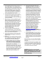
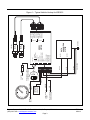
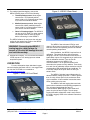
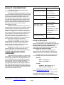
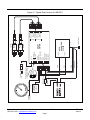
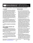
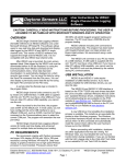
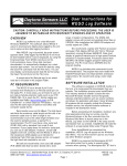
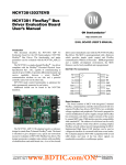
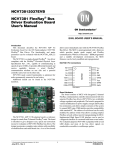
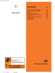
Daytona Sensors LLC Engine Controls and Instrumentation Systems Installation Instructions for WEGO 5 Dual Channel Wide-Band Exhaust Gas Oxygen Sensor System CAUTION: CAREFULLY READ INSTRUCTIONS BEFORE PROCEEDING OVERVIEW The WEGO 5 is a complete dual channel air/fuel ratio (AFR) system with built-in data logging. It can be used as a standalone unit or interfaced to an engine management or data acquisition system by means of 0-5 volt analog AFR outputs or CAN data bus at up to 1 Mbps. For CAN data bus applications, please contact our tech support at 386-322-7390. Optional dual channel AFR gauges displays are also available – refer to our website at www.daytonasensors.com for more details. The WEGO 5 unit logs one hour of data at 10 samples/second. Data logged includes sensor 1 and sensor 2 AFR values, engine RPM, a 0-5V analog input for sensors such as throttle position or manifold pressure, battery voltage, and sensor diagnostics. Data is downloaded with our WEGO 5 Log software by means of a built-in USB interface. Refer to the WEGO 5 Log software instructions for details. The compact size and wide 11-18 volt supply range allows operation from small rechargeable batteries in a broad spectrum of applications. The system uses low cost Bosch LSU 4.2 5-wire wide-band oxygen sensors. By utilizing miniature surface mount electronics technology, digital signal processing techniques, and a switching power supply for the sensor heater, the WEGO 5 provides the same level of accuracy as lab systems costing thousands of dollars. REPLACEMENT SENSORS AND ACCESSORIES The WEGO 5 uses standard Bosch LSU 4.2 sensors used on a VW production application (Bosch P/N 0 258 007 057/058 or VW P/N 021 906 262B). The proprietary VW connector is replaced with a smaller Deutsch DT-04-6P. We offer replacement sensors with the Deutsch connector installed. If you are testing multiple engines, we also offer additional 18 x 1.5 mm weld nuts for sensor mounting and 18 x 1.5mm hex socket plugs that screw into the weld nuts and allow removing sensors after tuning. Some engines using CD (capacitive discharge) ignitions may require a special tach adapter for engine RPM data logging. Please call our tech support at 386322-7390 for details. INSTALLATION 1. Turn off the ignition switch before proceeding. 2. Select a convenient mounting location for the Bosch sensors. In general, the sensors should be mounted as close to the exhaust valves or exhaust manifold as practical. When choosing a mounting location, allow several inches clearance for the sensor wire harness. The wire harness must exit straight out from the sensor. Do not loop the harness back onto the sensor body. The sensor responds to oxygen pressure. Excessive backpressure will cause a reading error. For turbocharged applications, you must mount the sensors downstream of the turbo. 3. For temporary use during dyno tuning, you can mount the Bosch wide-band sensors in place of the original equipment rear oxygen sensors (after the catalytic converter). You can also use sniffers in the tailpipe. For permanent mounting, 18 x 1.5 mm weld nuts must be welded onto the exhaust pipe. After welding, run an 18 x 1.5 mm tap through the threads. Failure to clean the threads may result in sensor damage. Note that most automotive muffler shops are familiar with oxygen sensor weld nut installation on custom pipes. Do not install the sensors until after the free air calibration procedure described in the following section. Always use an anti-seize lubricant such as Permatex 133A on the sensor threads. 4. Select a convenient mounting location for the WEGO 5. The unit is not sealed and must be mounted in a dry location away from sources of heat. We recommend underdash mounting or use in a dyno lab environment. The unit is not intended for underhood mounting. The unit can be secured by means of Velcro tape strips. Use nylon tie wraps to secure the wire harness near the unit. 5. Working with the clamping terminal blocks. All connections to the WEGO 5 terminal blocks must be clearly identified either by means of distinct wire Daytona Sensors LLC, 933 Beville Road, Suite 101-I, S. Daytona, FL 32119 (386) 322-7390 www.daytona-sensors.com Page 1 WEGO 5 9/2014 colors (suggested colors are shown on Figure 1) or the use of wire labels. If you use different wire colors, mark up Figure 1 for future reference. Refer to the Appendix for recommended wire labels. Wire should be stripped back 3/16-1/4 inch. No bare wire should be visible outside the terminal block. Use a miniature flat screwdriver to tighten the screws. The terminal blocks are removable and can be pulled straight out by the wires. 6. Connect the Bosch sensors to the 6 pin mating connectors on the supplied extension cables. You can shorten the extension cables if required. Longer 12 foot extension cables (P/N WEGO-CBL12) are also available. 7. Refer to Figure 1. Connect the WEGO 5 ground wires to a good frame ground location. Use 18 AWG wire for the power ground connection. If you are using a data acquisition system, connect the ground wires to the same point that the data acquisition system is grounded. Keep the ground connections as short as possible. Try to use an existing wire harness ground location. Do not ground the WEGO 5 to the battery minus terminal or to the engine. 8. Connect the WEGO 5 switched power and continuous battery power. You can usually find switched power at an accessory fuse on the fuse block. You can use the supplied fuse tap and 3/16” female crimp terminal for this purpose. 9. Optional signal hookups, including engine RPM and analog signal data logging, are explained in sections 10-12. 10. RPM signal. This connection is required to utilize the full capabilities of the WEGO 5. Depending on your vehicle type and engine control, there are three possible sources for the RPM signal: a. High level signal on the Coil- terminal of most inductive discharge type ignitions. This includes most original equipment (OE) ignitions except coil-on-plug with integrated drive electronics. For automotive distributorless or Harley-Davidson® single fire systems with multiple coils or coil packs, you can use any one of the Coil- signals. Refer to the vehicle wiring diagram for details. The Coilterminal will connect to an ignition module or engine control module (ECM). The Coil+ terminal will connect to switched +12V. b. Tach signal (preferred for best noise immunity). The WEGO 5 is compatible with industry standard 12V square wave tach signals such as what would be used to drive an Autometer or similar aftermarket tach. Most aftermarket capacitive discharge (CD) ignitions including the Daytona Sensors CD-1, MSD-6 and Crane HI-6 series have a tach output that you can use. 1999-2003 Harley-Davidson motorcycles with carbureted Twin Cam 88 engines have a tach output on pin 12 of the black ignition module connector. Most 2001 and later Harley-Davidson motorcycles with 36 pin Delphi fuel injection ECM have a tach output on pin 3 of the ECM connector. Motorcycle and small engine CD (capacitive discharge) ignitions. Many Japanese motorcycles and small engines use CD ignitions. Any engines with flywheel triggered systems fall into this category. These applications will require a special tach adapter P/N WEGO-TACH-ADAPT. If you have a Japanese motorcycle, download the WEGO Tach Adapter instructions from our website at www.daytona-sensors.com. Tips are provided for identifying the type of ignition system in use. c. Low level logic signal. This type of signal is found on late model vehicles, including many imports, that use coil-on-plug with integrated drive electronics. Refer to the vehicle wiring diagram for details. You can use the signal that goes from the ECM to any one of the coil-onplug units. During initial setup, you must configure the RPM signal level jumper on the left side of the WEGO 5 front panel. The WEGO 5 Dual Channel Log software is used to set the correct scaling for engine RPM in terms of pulses per revolution. The unit can easily be set up for operation with 1-12 cylinder engines. Refer to the software instructions for details. WARNING: Directly connecting the WEGO 5 RPM input to the coil of a CD type ignition will damage the unit and void the warranty. Daytona Sensors LLC, 933 Beville Road, Suite 101-I, S. Daytona, FL 32119 (386) 322-7390 www.daytona-sensors.com Page 2 WEGO 5 9/2014 BROWN TACH SIGNAL TO CONTINUOUS BATTERY POWER RED ORANGE TPS OR MAP SENSOR WITH 0-5V OUTPUT TO SWITCHED POWER TO ECM OR COIL- RPM GREEN 5V TACH COIL Daytona Sensors LLC, 933 Beville Road, Suite 101-I, S. Daytona, FL 32119 (386) 322-7390 www.daytona-sensors.com Page 3 BLACK 18 AWG BLACK BLUE WHITE RPM SIGNAL LEVEL JUMPER POSITIONS USB TO PC INPUT 2 INPUT 1 RPM INPUT ANALOG INPUT SENSOR 1 AFR OUTPUT SENSOR 2 AFR OUTPUT CAN-HI CAN-LO SWITCHED POWER BATTERY POWER POWER GROUND SIGNAL GROUND 5V RPM INPUT TACH SIGNAL LEVEL COIL CAN TERMINATOR USB PORT GROUND DATA ACQUISITION SYSTEM WEGO 5 SYSTEM SENSOR 1 BOSCH LSU 4.2 BOSCH LSU 4.2 TO SENSOR 1 TO SENSOR 2 SENSOR 2 WHITE (HTR-) GREEN (HTR+) RED (PUMP) BROWN (+5V) BLACK (CELL) WHITE (HTR-) GREEN (HTR+) RED (PUMP) BROWN (+5V) BLACK (CELL) Figure 1 – Typical Vehicle Hookup for WEGO 5 WEGO 5 9/2014 11. For analog signal data logging, connect the WEGO 5 analog input to one of the following: Figure 3 - WEGO 5 Rear Panel a. Throttle position sensor. Most engine controls use a TPS (throttle position sensor) with a 0-5 volt signal range. Refer to your service manual for details. b. Manifold pressure sensor. Most engine controls use a MAP (manifold pressure sensor) with 0-5 volt signal range. Refer to your service manual for details. c. Other 0-5V analog signals. The WEGO 5 can log any 0-5V signal. For other sensors, use a scope meter to check the signal before connecting it to the WEGO 5. The WEGO software is used to set the units and scaling for the analog input. Refer to the WEGO software instructions for details. WARNING: Connecting the WEGO 5 analog input to a high voltage (in excess of 12 volts) will damage the unit and void the warranty. 12. Optional AFR outputs. You can connect the WEGO 5 AFR outputs to 0-5V analog inputs on a data acquisition system. OPERATION For more information about wide-band oxygen sensors including the Bosch LSU 4.2, we suggest that you visit the Tech FAQ on our website at www.daytona-sensors.com. Figure 2 - WEGO 5 Front Panel The WEGO 5 has red status LEDs for each channel. When power is turned on, the LEDs blink at a slow rate until the corresponding sensor has reached normal operating temperature. After installation, the WEGO 5 requires free air calibration. This should be done with the sensors dangling in free air. The environment must be free of hydrocarbon vapors. We suggest that you perform the free air calibration outdoors. Turn the free air calibration trimpots on the WEGO 5 full counterclockwise. Turn on power and wait for 60 seconds so the system can fully stabilize. Then slowly turn each free air calibration trimpot clockwise until the corresponding LED starts flashing at a rapid rate. Try to set each trimpot at the point where its LED just starts to flash. The WEGO 5 includes internal diagnostics for abnormal battery voltage (less than 11 volts or greater than 18 volts), sensor open circuit, and sensor short circuit conditions. A fault condition causes the status LEDs to blink at the slow rate. The WEGO 5 will start logging data once both sensors have reached normal operating temperature. The unit stops logging data after any PC communications. Data logging will not restart until power is cycled off and on again. The unit stops logging data while a diagnostic code is set (however the code is logged). Refer to the software instructions for details. Daytona Sensors LLC, 933 Beville Road, Suite 101-I, S. Daytona, FL 32119 (386) 322-7390 www.daytona-sensors.com Page 4 WEGO 5 9/2014 EXHAUST CONSIDERATIONS Operating Mode Recommended AFR The WEGO 5 system may give inaccurate results in certain situations: Cold Start (first 30 sec) 11.5-12.5 AFR Excessive exhaust back pressure. Wide-band sensors are affected by back pressure. Excessive back pressure causes exaggerated AFR indications under rich and lean conditions, but has little effect at 14.7 AFR (stoichiometric). The WEGO 5 is intended to be used with a free flowing performance exhaust. Overly restrictive stock mufflers may cause excessive back pressure under wide open throttle. When used with a turbo system, the sensors must be mounted downstream of the turbo. Exhaust reversion. Reversion is the term for a negative pressure wave that can suck ambient air back into the exhaust and cause an erroneous lean AFR indication. Exhausts without mufflers, such as open headers or “drag pipes” on motorcycles, usually suffer from reversion effects and may not be suitable for use with the WEGO 5. Reversion effects will also occur with certain exhausts used on “bagger” style motorcycles, where two pipes split off near the rear cylinder. Reversion effects will be most noticeable at idle, part throttle low RPM cruise, and decel. Excessive scavenging. Turbo systems or tuned exhausts in combination with a high overlap camshaft profile can force unburned air and fuel mixture through the cylinder into the exhaust and cause an erroneous rich AFR indication. Misfiring. If the AFR is so rich that the engine misfires, high levels of oxygen will remain in the exhaust gas and result in an erroneous lean indication. GASOLINE ENGINE TUNING GUIDELINES Higher AFR values correspond to a leaner (less fuel) condition. The practical operating range for most engines using gasoline fuel is from approximately 11.5 to 14.7 AFR. Combustion of a stoichiometric mixture (exactly enough air to burn all the fuel) results in 14.7 AFR indication. Automotive engines with catalytic converters operate near 14.7 AFR during cruise and idle. Race engines usually require a richer mixture to limit cylinder head temperature and prevent detonation. The table below lists reasonable AFR values for race engines without emission controls. 0.78-0.85 Lambda Idle 12.8-13.5 AFR 0.87-0.92 Lambda Part Throttle Cruise 13.0-14.0 AFR 0.88-0.95 Lambda Wide Open Throttle (normally aspirated) 12.5-12.8 AFR 0.85-0.87 Lambda Values down to 11.5 AFR or 0.78 Lambda may be used to reduce detonation) Wide Open Throttle (turbo/supercharged) 10.8-11.8 AFR 0.73-0.80 Lambda DATA ACQUISTION The 0-5 volt analog outputs (white and blue wires) from the WEGO 5 are compatible with most data acquisition systems that have available analog inputs. We do not offer any technical assistance on interfacing to your data acquisition system. You must contact the vendor for support. WEGO units are useful in a wide range of engine tuning and testing applications. After free air calibration, accuracy is 0.1 AFR or ±0.007 Lambda. All WEGO units have the same scaling for the 0-5 volt analog outputs on the white and blue wires: Gasoline: AFR = 2 x (Vout + 5) or Vout = (0.5 x AFR) - 5 Lambda: Lambda = .1361 x (Vout + 5) or Vout = (7.345 x Lambda) - 5 Additional scale factors are listed on our Tech FAQ at www.daytona-sensors.com. Note that when power is first turned on and the sensors are not yet at their normal operating temperature, the analog outputs are held at less than Daytona Sensors LLC, 933 Beville Road, Suite 101-I, S. Daytona, FL 32119 (386) 322-7390 www.daytona-sensors.com Page 5 WEGO 5 9/2014 0.20 volts. During free air calibration and while the WEGO 5 status LEDs are rapidly blinking, the analog outputs will be near 5.0 volts. EXHAUST SNIFFERS WEGO 5 units can be used with easily fabricated exhaust sniffers that allow temporary installation on most automobiles and motorcycles for tuning and diagnostic purposes, including vehicles with catalytic converters. The exhaust sniffers are constructed from materials that are readily available at any hardware store. For more details, download the Automotive Exhaust Sniffer Tech Note and Motorcycle Exhaust Sniffer Tech Note from our website at www.daytona-sensors.com. Daytona Sensors LLC, 933 Beville Road, Suite 101-I, S. Daytona, FL 32119 (386) 322-7390 www.daytona-sensors.com Page 6 WEGO 5 9/2014 TO ECM OR COILBROWN TACH SIGNAL GREEN ORANGE RED 5V TACH COIL Daytona Sensors LLC, 933 Beville Road, Suite 101-I, S. Daytona, FL 32119 (386) 322-7390 www.daytona-sensors.com Page 7 BLACK 18 AWG BLACK 18 AWG BLACK BLUE WHITE RPM SIGNAL LEVEL JUMPER POSITIONS ARMING SWITCH TPS OR MAP SENSOR WITH 0-5V OUTPUT RPM USB TO PC INPUT 2 INPUT 1 RPM INPUT ANALOG INPUT SENSOR 1 AFR OUTPUT SENSOR 2 AFR OUTPUT CAN-HI CAN-LO SWITCHED POWER BATTERY POWER POWER GROUND SIGNAL GROUND 5V RPM INPUT TACH SIGNAL LEVEL COIL CAN TERMINATOR USB PORT WHITE (HTR-) GREEN (HTR+) RED (PUMP) BROWN (+5V) BLACK (CELL) WHITE (HTR-) GREEN (HTR+) RED (PUMP) BROWN (+5V) BLACK (CELL) DYNO GROUND GROUND DATA ACQUISITION SYSTEM WEGO 5 SYSTEM SENSOR 1 BOSCH LSU 4.2 BOSCH LSU 4.2 TO SENSOR 1 TO SENSOR 2 SENSOR 2 Figure 4 – Typical Dyno Hookup for WEGO 5 WEGO 5 9/2014 DYNO WIRING HOOKUP WEGO POWER REQUIREMENTS Refer to Figure 4. The power supply must be located in close proximity to the WEGO unit. We recommend mounting the WEGO unit on a panel next to the dyno data acquisition system and then running extension cables out to the sensors in the dyno room. Keep all power and ground connections as short as possible. Follow the exact layout shown in Figure 4. Do not add additional terminal blocks or connectors to power or ground connections. WEGO systems are intended for nominal 12 volt automotive applications. Nominal 12 volt automotive electrical systems on alternator equipped vehicles typically operate at 13.8-14.4 volts while the engine is running. The WEGO can operate from 9.0 to 18.0 volts. The power supply should remain on during operation of the WEGO. The arming switch shown in Figure 4 is used in place of an ignition switch on a vehicle to cycle power to the WEGO. To avoid loss of logged data, always turn the arming switch off first and wait 5 seconds before turning the power supply off. DYNO GROUNDING Improper grounding will cause serious problems. The dyno frame or chassis must be connected to building electrical ground in accordance with National Electrical Code (NEC) requirements. Vehicles operated on a chassis dyno will generate considerable electrostatic charge. The vehicle must be grounded to the dyno frame while in operation. You can use a length of 16 AWG wire with one end secured to the dyno frame and the other end equipped with a heavy duty alligator clip that is attached to the vehicle frame or other vehicle ground point. Failure to ground the vehicle will lead to electrostatic discharge (ESD) across the WEGO sensor damaging the sensor and WEGO unit. WEGO units also feature low power consumption (about 2 amps). For small engine applications, you can power the WEGO for over one hour from a 12 volt gel cell type rechargeable battery, such as the type used for backup power in alarm systems. Vehicles with nominal 12 volt total loss electrical systems (no alternator) can momentarily drop below the 9.0 volt minimum level when heavy loads, such as fans or nitrous solenoids engage. This will cause the WEGO to reset and result in a loss of data for 10-15 seconds. Vehicles with nominal 16 volt electrical systems equipped with race type alternators may reach 18.6 volts while the engine is running. The WEGO will shut off if the voltage exceeds 18.0 volts. Call our tech support before attempting to install any WEGO system on a nominal 16 volt electrical system with an alternator. CAUTION: To avoid damage to the WEGO, a secure ground connection must be established between the vehicle and dyno chassis before connecting tach or analog signals. Daytona Sensors LLC, 933 Beville Road, Suite 101-I, S. Daytona, FL 32119 (386) 322-7390 www.daytona-sensors.com Page 8 WEGO 5 9/2014 CAN DATA BUS Low battery voltage CAN data is sent at 1 Mbps with 20 transmissions/sec. CAN data format is: High battery voltage SID, CH1_LAMBDA_HI, CH1_LAMBDA_LO, CH2_LAMBDA_HI, CH2_LAMBDA_LO, CH1_SENS_RES, CH2_SENS_RES, DIAG_CODE, BAT_VOLTS Sensor short circuit Sensor open circuit Sensor cold Where: BAT_VOLTS (battery voltage) is an 8 bit binary digit scaled 255 = 20 volts, i.e. SID is a customer assigned CAN standard identifier CH is an abbreviation for channel (1 or 2) CHN_LAMBDA_HI:CHN_LAMBDA_LOW is a 16 bit binary digit scaled 1024= 1 Lambda, i.e. Lambda= Data/1024 The minimum data value is $1CA (0.45 Lambda) and the data value stays at $994 (2.4 Lambda) under very lean conditions until free air condition is reached, at which point the data value jumps to $7FFF. The unit will report zero Lambda data while cold or during diagnostic code conditions. CHN_SENS_RES (sensor resistance) is an 8-bit value in ohms (80 ohms nominal, significantly lower values indicate overheating) 1 (reported on channel 1 only, threshold is 9v) 2 (reported on channel 1 only, threshold is 18v) 3 4 5 Bat_Volts = (20 x Data)/255 If the WEGO 5 is the last device at the end of the CAN data bus, install the CAN terminator jumper on the left side of the WEGO front panel. For CAN data bus applications, please contact our tech support at 386-322-7390. TROUBLESHOOTING FLOWCHART Follow the troubleshooting flowchart shown on the next page for each channel. Experience has shown that most units returned for warranty are OK and another problem, such as user error, degraded sensors, or bad power connections is later identified. DIAG_CODE has the lower nibble corresponding to channel 1 and the upper nibble corresponding to channel 2 with assignments: CAUTION: Racing gasoline containing lead will quickly degrade the sensors. Under these conditions, expected sensor life is less than 10 hours. There is no warranty on sensors. CAUTION: WEGO 5 units are not sealed. These units are intended for dash mounting or use in dry environments. There is no warranty on units with moisture damage. Daytona Sensors LLC, 933 Beville Road, Suite 101-I, S. Daytona, FL 32119 (386) 322-7390 www.daytona-sensors.com Page 9 WEGO 5 9/2014 Troubleshooting Flowchart STARTING POINT NOTE: ALL TESTS PERFORMED WITH SENSORS IN FREE AIR DO STATUS LEDS SLOWLY BLINK WHEN POWER IS FIRST TURNED ON? NO YES VERIFY +12V POWER ON RED WIRE. VERIFY BLACK WIRES CONNECTED TO GROUND. IS PROBLEM FIXED? NO DO STATUS LEDS CONTINUE SLOWLY BLINKING 60 SECONDS AFTER POWER UP? YES REPLACE WEGO YES NO PERFORM FREE AIR CALIBRATION. IS CALIBRATION SUCCESSFUL? DONE NO MEASURE VOLTAGE LEVEL ON RED WIRE WITH DVM. IS IT GREATER THAN 11 VOLTS? YES REPLACE SENSOR(S). IS PROBLEM FIXED? NO REPLACE WEGO YES NO NO WEGO REQUIRES MINIMUM 11 VOLTS. FIX UNDERLYING PROBLEM WITH VEHICLE ELECTRIC SYSTEM. YES REPLACE SENSOR(S). IS PROBLEM FIXED? REPLACE WEGO DONE YES DONE IS PROBLEM FIXED? NO CALL TECH SUPPORT Daytona Sensors LLC, 933 Beville Road, Suite 101-I, S. Daytona, FL 32119 (386) 322-7390 www.daytona-sensors.com Page 10 YES DONE WEGO 5 9/2014 APPENDIX – RECOMMENDED PARTS AND SUPPLIERS PRESSURE SENSORS If the vehicle does not have a factory ECM that provides +5 volt power for a standard automotive type MAP sensor, you can use an industrial sensor, such as the SSI Technologies P51 series. These can be powered directly from +12 volt and provide a 1-5 volt output. P/N P51-15-A-UB-I36-5V-000-000 has a 0-15 psia range and is suitable for normally aspirated engines. Other versions with higher pressure ratings are available for boosted applications. These sensors are available from Digi-Key at www.digikey.com and additional information is available on the WEGO Tech FAQ on our website. WIRE Wire supplied with most automotive accessories is usually un-tinned copper with a low number of strands. The unprotected copper in this inexpensive wire quickly oxidizes, especially when in contact with dissimilar metals on terminals. The low number of strands limits life in applications where flexing occurs. We recommend the use of high quality industrial grade wire with tinned copper strands and a high strand count. 18-20 AWG sizes can be used for all signal and low current applications. 16-18 AWG is adequate for power and ground wiring. Carol UL grade 1007/1015 wire is available from Digi-Key. P/N Description C2040X-100 20 AWG wire (100 foot spool) C2064X-100 18 AWG wire (100 foot spool) C2104X-100 16 AWG wire (100 foot spool) C2105X-100 14 AWG wire (100 foot spool) Note: replace X with color code B=Black, W=White, R=Red, G=Green, A=Orange, Y=Yellow, L=Blue, N=Brown, S=Gray, V=Violet CRIMP TERMINALS High quality crimp terminals and a proper crimping tool are required to make reliable electrical connections. Crimp terminals commonly sold in automotive and hardware stores have brittle vinyl insulation that easily cracks. We recommend the use of high quality industrial grade nylon insulated crimp terminals. The following parts are available from DigiKey. P/N A27241 A27246 A27248 A27262 A27264 A27288 A27291 A0911 Description 16-20 AWG #10 ring tongue terminal 16-20 AWG 1/4” ring tongue terminal 16-20 AWG 3/8” ring tongue terminal 14-16 AWG 1/4” ring tongue terminal 14-16 AWG 3/8” ring tongue terminal 10-12 AWG 1/4” ring tongue terminal 10-12 AWG 3/8” ring tongue terminal 18-22 AWG .110” female quick disconnect terminal MNU18-187DFIK 18-22 AWG .187” female quick disconnect terminal MNU18-250DFIK 18-22 AWG 1/4” female quick disconnect terminal MNU14-250DFIK 14-16 AWG 1/4” female quick disconnect terminal A1069 16-22 AWG butt splice A1080 14-16 AWG butt splice A1086 10-12 AWG butt splice FUSES AND FUSE TAPS ATC series fuses and fuse holders commonly used for automotive applications are only available in 40 amp and lower ratings. For high current applications, we recommend the heavy duty 50 amp Littlefuse Maxi Fuse series available from Digi-Key. P/N F1085 F1038 Description Maxi fuse block 50 amp Maxi fuse SWITCHES All switches used in performance applications should be sealed. Representative sealed toggle and rocker style switches available from Digi-Key are listed below. P/N 480-2191 360-2278 Daytona Sensors LLC, 933 Beville Road, Suite 101-I, S. Daytona, FL 32119 (386) 322-7390 www.daytona-sensors.com Page 11 Description Honeywell SPDT toggle switch NKK SPDT rocker switch WEGO 5 9/2014 RELIABLE CONNECTIONS TO EXISTING SIGNALS For some applications, you may have to tap into existing signal wires on the vehicle. We caution against using any of the so called “vampire clips” that make an insulation displacement connection. These have proven very unreliable in racing applications. They may even cause the original wire to fray and break. We suggest soldering any connections to existing signals. Use a stripping tool to cut through and push back about 1/4” of insulation at the spot on the original wire where you plan to make the connection. Wrap several turns of the new wire around, solder, insulate with self vulcanizing electrical tape, and use two cable ties to secure the splice as shown. Regular electrical tape will tend to unravel. Self vulcanizing electrical tape is available from Digi-Key as their P/N W213. SUPPLIERS Suppliers referenced in the Appendix are listed in the table below. Additional suppliers for connectors, electronic tools, mechanical hardware, and test equipment are listed on our website at www.daytona-sensors.com/tech_tools.htm. Supplier Phone Website Digi-Key 1-800-344-4539 www.digi-key.com Mouser 1-800-346-6873 www.mouser.com Newark 1-800-463-9275 www.newarkinone.com State Wire & Terminal 1-800-922-6527 www.statewire.com Daytona Sensors LLC, 933 Beville Road, Suite 101-I, S. Daytona, FL 32119 (386) 322-7390 www.daytona-sensors.com Page 12 WEGO 5 9/2014