1
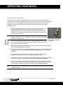
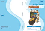
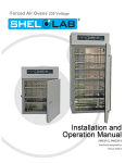
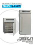
Vacuum Oven 230 Voltage Installation and Operation Manual SVAC9-2 Previously designated as VPX9-2 SVAC9-2 Vacuum Oven 230 Voltage Previously designated VPX9-2 Vacuum Oven Installation and Operation Manual Part Number (Manual): 4861570 Revision: May 5, 2014 Pictured on front: Standard powder coat paint Below: Stainless steel exterior clean room option These units are TÜV CUE listed as vacuum ovens for professional, industrial, or educational use where the preparation or testing of materials is done at approximately atmospheric pressure and no flammable, volatile, or combustible materials are being heated. These units have been tested to the following requirements: CAN/CSA C22.2 No. 61010-1:2012 CAN/CSA C22.2 No. 61010-2-010 + R:2009 UL 61010A-2-010:2002 UL 61010-1:2012 EN 61010-1:2010 EN 61010-2-010:2003 2|Page TABLE OF CONTENTS INTRODUCTION........................................................................................................................................... 4 General Safety Considerations ................................................................................................................. 4 Engineering Improvements ....................................................................................................................... 4 Contacting Assistance ............................................................................................................................... 5 Clean Room Option ................................................................................................................................... 5 RECEIVING YOUR OVEN ............................................................................................................................ 6 Inspecting the Shipment ............................................................................................................................ 6 Vacuum Pump ........................................................................................................................................... 6 Gaskets ..................................................................................................................................................... 6 Returning the Shipment ............................................................................................................................ 7 Recording Data Plate Information ............................................................................................................. 7 GRAPHIC SYMBOLS ................................................................................................................................... 8 INSTALLATION ............................................................................................................................................ 9 Location ..................................................................................................................................................... 9 Lifting and Handling .................................................................................................................................. 9 Power Source .......................................................................................................................................... 10 Leveling ................................................................................................................................................... 10 Vacuum Plumbing ................................................................................................................................... 11 Vent and Gas Plumbing .......................................................................................................................... 11 Shelving Installation ................................................................................................................................ 12 Cleaning .................................................................................................................................................. 12 Burn In ..................................................................................................................................................... 12 CONTROL OVERVIEW .............................................................................................................................. 13 Valves and Circuit Breakers .................................................................................................................... 15 OPERATION ............................................................................................................................................... 16 Operating Precautions ............................................................................................................................ 16 Theory of Operation ................................................................................................................................ 17 Setting up the Oven ................................................................................................................................ 18 First Use Burn In (Recommended) ......................................................................................................... 19 Verify Vacuum Functionality and Integrity ............................................................................................... 19 Setting the Temperature Controller Set Point ......................................................................................... 20 Calibrating the Unit .................................................................................................................................. 21 Setting the Over Temperature Limit Control ........................................................................................... 22 Programmed Operations ......................................................................................................................... 23 USER MAINTENANCE ............................................................................................................................... 24 Cleaning .................................................................................................................................................. 24 Disinfecting .............................................................................................................................................. 24 Storage .................................................................................................................................................... 25 Vacuum Pump Maintenance ................................................................................................................... 25 Unit SPECIFICATIONS .............................................................................................................................. 26 Weight ..................................................................................................................................................... 26 Dimensions .............................................................................................................................................. 26 Capacity .................................................................................................................................................. 26 Shelf Capacity by Weight ........................................................................................................................ 26 Temperature ............................................................................................................................................ 27 Power ...................................................................................................................................................... 27 REPLACMENT PARTS LIST ..................................................................................................................... 28 3|Page INTRODUCTION Thank you for purchasing a Sheldon Manufacturing SVAC9-2 large capacity vacuum oven. We know that in today’s competitive marketplace, customers have many choices when it comes to constant temperature equipment. We appreciate you choosing ours. Our continued reputation as a leading laboratory product manufacturer rests with your satisfaction. Sheldon Manufacturing, Inc. stands behind our products, and we will be here if you need us. These vacuum ovens are intended for professional, industrial, and educational applications. The ovens are not intended for use at hazardous or household locations. Before you use the oven read this entire manual carefully to understand how to install, operate, and maintain the oven in a safe manner. Keep this manual available for use by all oven operators. Ensure that all operators are given appropriate training before the oven begins service. Note: Failure to follow the guidelines and instructions in this manual may create a protection impairment by disabling or interfering with the unit’s safety features. This can result in injury or death. GENERAL SAFETY CONSIDERATIONS Your oven and its recommended accessories have been designed and tested to meet strict safety requirements. For continued safe operation of your oven, always follow basic safety precautions including: Only use this equipment for its intended range of applications. Follow any local or regional ordinances in your area covering the use of this unit. Use only approved accessories. Do not modify system components. Any alterations or modifications to your oven may be dangerous and will void your warranty. Always hardwire the unit’s power feed to an earth grounded electrical source that conforms to national and local electrical codes. If the unit is not earth grounded, parts such as, knobs and controls may conduct electricity and cause serious injury. Avoid damaging the power feed. Do not bend it excessively, step on it, place heavy objects on it. A damaged power feed can easily become a shock or fire hazard. Never use a power feed after it has been damaged. Do not position the equipment in such a manner as to make it difficult to disconnect or uncouple the power feed. Do not attempt to move the unit while in operation or before the unit has cooled. ENGINEERING IMPROVEMENTS Sheldon Manufacturing continually improves all of its products. As a result, engineering changes and improvements are made from time to time. Therefore, some changes, modifications, and improvements may not be covered in this manual. If your unit’s operating characteristics or appearance differs from those described in this manual, please contact your Shel Lab dealer or customer service representative for assistance. 4|Page INTRODUCTION (CONTINUED) CONTACTING ASSISTANCE If you are unable to resolve a technical issue with your vacuum oven, please contact Sheldon Technical Support. Phone hours for Sheldon Technical Support are 6am – 4:30pm Pacific Coast Time (west coast of the United States, UTC -8). Please have the following information ready when calling or emailing Technical Support: the model number and the serial number (see page 7). EMAIL: [email protected] PHONE: 1-800-322-4897 extension 2, or (503) 640-3000 FAX: (503) 640-1366 CLEAN ROOM OPTION An optional stainless steel exterior is available for the SVAC9-2 from Sheldon Manufacturing. Suitable for many cleanroom applications, the paint-free exterior surfaces are corrosion resistant and help to prevent contamination from paint flecking and surface particle retention. Special Quote (SQ) Number: 910-980-0004. This option must be chosen prior to the oven being built. All SVAC9-2 ovens come with stainless steel interiors. Figure 1: SVAC9-2 with Stainless Steel Exterior 5|Page RECEIVING YOUR OVEN Before leaving our factory, all SVAC ovens are packaged in high-quality shipping materials to provide protection from transportation-related damage. When an oven leaves our factory, safe delivery becomes the responsibility of the carrier. Damage sustained during transit is not covered by the oven’s warranty. When you receive your SVAC9-2 oven, inspect it for concealed loss or damage to its interior and exterior. If you find any damage to the oven, then follow the carrier’s procedure for claiming damage or loss. INSPECTING THE SHIPMENT Carefully inspect the shipping carton for damage. Report any damage to the carrier service that delivered the SVAC oven. If the carton is not damaged, open the carton and remove the contents. The unit should come with an Installation and Operation Manual, warranty card, and a Certificate of Compliance, the simplified Watlow EZ-Controller Programing Guide, and a Watlow EZ-Zone User Manual. Verify that the correct number of shelves, shelf slides, and leveling feet have been included (see the following table for quantities). The oven is not supplied with a vacuum pump. Included accessories Shelves Shelf Clips Leveling Feet Oil Drain Tray 3 12 4 1* *The oil drain tray included for use with vacuum pumps that produce oil leakage. Carefully check all packaging before discarding. Save the shipping carton until you are certain that the unit and its accessories function properly. VACUUM PUMP The SVAC9-2 does not come supplied with a vacuum pump. All maintenance and instructional information should be obtained from the pump manufacturer, if it not shipped with the pump. Sheldon Manufacturing offers vacuum pumps for sale compatible with a variety of applications and processes. Mounting studs and an outlet for powering a vacuum pump are installed in the cabinet inside the base of the oven. See the Vacuum Plumbing entry in the Installation section (page 11) for more information on plumbing. GASKETS The SVAC9-2 comes with Viton door and window gaskets installed. These are rated to 205°C and resistant to acids, but not solvents. Sheldon Manufacturing also offers Buna gaskets resistant to solvents, and rated to 100°C. 6|Page RECEIVING YOUR OVEN (CONTINUED) RETURNING THE SHIPMENT If you must return the oven for any reason, first contact your service representative for a return of material authorization (RMA). You must provide the unit’s data plate information. See Recording Data Plate Information below. RECORDING DATA PLATE INFORMATION Locate the data plate on the back of the oven next to the power inlet. The data plate contains the oven model number and serial number. Enter this information below for future reference. Date Plate Information Model Number Serial Number 7|Page GRAPHIC SYMBOLS The oven is provided with multiple graphic symbols on its interior and exterior surfaces. The symbols identify hazards and the functions of the adjustable components, as well as important notes in the user manual. Symbol Definition Indicates that you should consult your service manual for further instructions. Indique que l'opérateur doit consulter le manuel d'utilisation pour y trouver les instructions complémentaires. Indicates the Over Temperature Limit system Indique le système de dépassement de temperature Indicates AC Power Repère le courant alternative Indicates I/ON and O/OFF I repère de la position MARCHE de l'interrupteur d'alimentation O repère de la position ARRÊT de l'interrupteur d'alimentation Indicates vacuum pump is active. Indique la pompe à vide est active. Indicates a Manually Adjustable control Indique un bouton réglable manuellement Indicates a Potential Shock Hazard Signale danger électrique WEEE Directive compliant logo Indicates the unit should be recycled (Not disposed of in land-fill) Indique l’appareil doit être recyclé (Ne pas jeter dans une décharge) Indicates protective earth ground Repère terre électrique Indicates: Caution hot surface Indique: Avertissement symbole de surface chaude 8|Page INSTALLATION Installation of the unit requires permanent connect wiring (commonly known as hardwiring) and should be performed by a qualified electrical technician. All other steps can be performed by the end user. This oven is intended for use indoors at room temperatures between 15C and 40C (59F and 86F), at no greater than 80% Relative Humidity (at 25C / 77F). Allow a minimum of 12 inches (30cm) between the oven and any walls or partitions, as well as 12 inches (30cm) of vertical headspace clearance above the top of the oven for unobstructed airflow and cooling. Operating the unit outside of these conditions may adversely affect the temperature range and stability. For conditions outside those listed above, please contact your distributor or Sheldon Sales to explore other ovens suited to your laboratory or production environment. LOCATION When selecting a location to install the oven, consider all environmental conditions that can affect unit’s effective temperature range, uniformity, and stability. For example: Other ovens, autoclaves, and any device that produces significant radiant heat Heating and cooling ducts, or other sources of fast moving air currents High-traffic areas Direct sunlight LIFTING AND HANDLING The oven is heavy. Use appropriate lifting devices that are sufficiently rated for these loads. Follow these guidelines when lifting the oven: Lift the oven only from its bottom surface. Doors, handles, and knobs are not adequate for lifting or stabilization. Restrain the oven completely while lifting or transporting so it cannot tip. Remove all moving parts, such as shelves and trays, and lock doors in the closed position during transfers to prevent shifting and damage. 9|Page INSTALLATION (CONTINUED) POWER SOURCE This oven is intended for a 230 volt, 20 Amp, 50/60 Hz application. Check the oven’s data plate to verify voltage and ampere requirements before connecting to a power source. The oven’s power feed must be wired into an earth grounded source. The power source for the oven must conform to all national and local electrical codes Supplied voltage must not vary more than 10% from the data plate rating. Damage to the oven may result if supplied voltage varies more than 10%. Before energizing the oven it must be earth grounded using the protective conductor terminal (green with yellow stripe wire. Do not remove the protective conductor (earth connection). Removing the protective conductor will negate the oven’s protections against potentially dangerous electric shocks and create a possible fire hazard. A separate circuit is recommended to prevent possible loss of product due to overloading or failure of other equipment on the same circuit. A switch or circuit-breaker must be used in the building installation. The required circuit-breaker is 20A The wires for power source connection should be in accordance with the following: SVAC9-2 (VPX9-2): Green/Yellow – Earth; Red – Hot; Black – Hot. The Disconnect must be in close proximity to the unit and within easy reach of the operator. The Disconnect must be marked as the disconnecting device for the equipment. LEVELING Make sure that the oven is level and stable. Each SVAC9-2 oven ships with four leveling feet. Insert one leveling foot into each of the four holes in the bottom corners of the oven. Stand the oven upright. Then, adjust the foot at each corner until the oven stands level and solid without rocking. To raise a foot, turn it in a counterclockwise direction; to lower a foot, turn it in a clockwise direction. Note: To prevent damage when moving the oven, turn each of the four leveling feet completely clockwise. 10 | P a g e INSTALLATION (CONTINUED) VACUUM PLUMBING The SVAC9-2 oven is provided with two (2) KF-25 vacuum fittings on its main vacuum line. The first is located on the back of the oven (Figure 2), and feeds directly into a 1 inch (2.54 cm) port in the back of oven chamber. A vacuum supply plumbed to this back fitting must have a control valve between the source and the fitting. A second KF-25 fitting plumbed to a 0.5 inch (1 cm) section of the main vacuum line, and is located inside the cabinet beneath the oven chamber (See Figure 5). It is intended to be plumbed to a vacuum pump mounted inside the cabinet, and is located just above the vacuum pump mounting studs set in the cabinet floor. The fitting is also next to the 230VAC outlet controlled by the vacuum power switch on the main control panel, and intended to provide power to a cabinet mounted pump. Figure 2: KF-25 Fitting – Back of Oven Figure 3: Front Cabinet Panel Removed The vacuum valve located in the recessed box on the front of the oven controls application of vacuum generated by a pump connected to the cabinet KF-25 fitting. Note: The cabinet front and back panels must be reinstalled and secured prior to powering the oven. Operating the oven with one or both panels off exposes powered electrical lines and components. VENT AND GAS PLUMBING Figure 4: Cabinet Access Port – Back Deck of Oven The vent valve control on the front panel controls a 0.5 inch (1 cm) oven chamber inlet located inside the cabinet next to the KF-25 vacuum fitting and vacuum line. A cylinder of a neutral purging gas such as, nitrogen or argon, may be connected to the venting inlet. A gas line from a purging gas cylinder may be introduced into the cabinet through the cabinet access port on the back deck of the oven (Figure 4). Ensure that the gas line does not make contact with the metal vacuum line as the vacuuming line may grow hot during operation. Figure 5: Vacuum and Vent Plumbing in the Cabinet Vent Valve Control Vacuum Power Outlet Switch Vacuum Valve Control Vent Inlet Vacuum Pump Power Outlet Cabinet KF-25 Vacuum Fitting 11 | P a g e INSTALLATION (CONTINUED) SHELVING INSTALLATION Perform the following steps to install the oven shelves: 1. Install the shelf clips in the slots located on the sides of the chamber interior, four (4) per shelf. 2. Squeeze each clip, insert the top tab first, and then the bottom tab using a rocking motion. 3. Hang the metal shelves from the clips. Figure 6: Shelving Clips CLEANING The oven interior was cleaned at the factory but not sterilized. See the Cleaning topic in the User Maintenance section for more information. BURN IN The oven should be run through a burning in process before being used for normal operations. This is done to eliminate smoking from the protective coatings on the oven’s heating elements at temperatures above 150˚C. Please see the Burn In procedure in the Operation Section. 12 | P a g e CONTROL OVERVIEW Figure 7: Control Panel SVAC9-2 and Watlow Temperature Controller Watlow Controller Details THE EASY ZONE KEY 1 INITIATES AND ENDS HEATING PROFILES CURRENT OVEN CHAMBER TEMPERATURE 20.0 C THE RESET KEY SCROLLS 1 PAGE BACK EZ1 RES E T THE UP ARROW KEY ADJUSTS SET POINTS OR CHANGES PARAMETERS 20.0 TEMPERATURE SET POINT (YOUR DESIRED TEMPERATURE) INDICATES THAT THE CONTROLLER IS POWERING THE OVEN’S HEATER EZ2 2 THE DOWN ARROW KEY ADJUSTS SET POINTS OR CHANGES PARAMETERS RAMPING SYMBOL INDICATES THAT A HEATING PROFILE IS RUNNING THE ADVANCE KEY SCROLLS THROUGH MENUS AND PARAMETER LISTS Power Switch Unit The main power switch on the control panel (green lighted I/O) controls all power to the unit and must be in the I (ON) position before any systems are operational. The switch will be lighted when in the on position. Power Switch Vacuum This I/O (on / off) switch is marked VACUUM and controls power to a vacuum pump plugged into the 230VAC outlet in the cabinet. The switch will illuminate when in the on position. Over Temperature Limit Thermostat (OTL) Labeled SET OVER TEMPERATURE and equipped with a graduated dial and independent temperature probe, the OTL system guards against an uncontrolled rise in oven chamber temperature. This allows continued operation of the oven in the event of a main controller failure, until the problem can be corrected. Please see the OTL entry in the Theory of Operation section on page 17 for a more detailed description of the system. 13 | P a g e CONTROL OVERVIEW (CONTINUED) Main Temperature Controller The main temperature control is labeled TEMPERATURE SET, and consists of a Watlow EZ-Zone Controller. The control is provided with a digital display and up / down arrow keys for adjusting the oven’s temperature set point, performing a calibration, and choosing pages and adjusting parameter settings while setting up heating profiles. The EZ1 button is used to launch and abort programmed heating profile (see the Programmed Operations section). The green advance key is used to scroll through parameters lists. The reset button is used to scroll the display back to the previous page while programing heating cycles. Pressing the reset button repeatedly with return the display to the home page. Note: On some older Watlow Controllers the Reset button may be labeled with an infinite ∞ symbol rather than RESET. Vacuum Gauge Labeled VACUUM SET, this is a digital gauge that shows the chamber vacuum level in measurements of Torr and m/Torr. The gauge display activates automatically when the Main Power switch is activated. Note: In the SVAC9-2 vacuum oven, the InstruTech 301 VGC301 Convection Vacuum Gauge Controller is intended for use as an automatically functioning vacuum gauge and display with no required user inputs. Users interested in employing the VGC310 for other applications should obtain a copy of the controller’s user manual from InstruTech, Inc. Other functions include displaying the chamber vacuum pressure in units other than torr. Reset Button The red reset button on the control panel is used to reset two power relays that are disconnected by the Over Temperature Limit System in the event of its activation, or by power outages. Reset must be pushed after each OTL interruption of heating or power outage. The button should also be pushed during the initial setup of the oven. 14 | P a g e CONTROL OVERVIEW (CONTINUED) VALVES AND CIRCUIT BREAKERS Vacuum Valve This valve is located just below the control panel in a recessed box, and marked VACUUM. It adjusts the amount vacuum applied to the chamber, when the vacuum is supplied from the KF-25 fitting located in the bottom cabinet. Turning the valve counterclockwise applies vacuum to the main vacuum line and oven chamber. Clockwise closes off the supply. Vent Valve This valve is located to the left of Vacuum Valve. When turned counterclockwise, the valve allows air to enter the chamber from an inlet in the cabinet, returning it to atmospheric pressure. The vent must be closed (clockwise) before applying vacuum to the chamber. Failure to do so will likely result in damage to the vacuum pump. The vent valve is commonly used to purge the oven chamber with a neutral gas provided by a compressed gas cylinder attached to the vent inlet. Circuit Breakers The SVAC9-2 oven comes equipped with two (2) 20 amp circuit breakers. If a breaker trips, turn the oven’s power switch to off, and locate a cause for the overcurrent before resetting the breaker. 15 | P a g e OPERATION OPERATING PRECAUTIONS Warning: The SVAC9-2 oven is not an explosion proof unit! The oven is not designed to safely contain combustible gasses. Do not place explosive, combustible, or flammable materials into the chamber. 1. Close and latch the door by swinging the latching arm into place. Then turn the knob clockwise until it grabs and the door is snug against the body. This will ensure a good seal. 2. When placing objects in the chamber be mindful of the temperature sensing probes mounted on the back wall. 3. The bottom surface of the chamber should not be used as a work surface. 4. Do not operate the oven in an environment with noxious fumes. 5. Do not place sealed or filled containers in the oven in the vacuum oven chamber. 6. Do not place mercury thermometers in the vacuum oven. 7. The SVAC9-2 oven is not designed for use in Class I, II, or III locations as defined by the US National Electric Code. Warning Hot Surfaces: These areas are marked with Hot Surface labels. Proper PPE should be employed to minimize risk to burn. Avertissement Surface Chaude: Ces zones sont marqués avec des étiquettes de Surface chaude. Les EPI approprié devraient être employée pour réduire au minimum le risque de brûler. 16 | P a g e OPERATION (CONTINUED) THEORY OF OPERATION The SVAC9-2 is intended for use in closed-cycle, under-vacuum applications such as, drying, baking out volatiles, and evolutions of molecular clouds. The oven is not built to operate exposed to free atmosphere or circulate air within the chamber. Running the oven with the door or vent open risks damaging the vacuum pump and the integrity of the oven. A cylinder of neutral gas may be connected to the vent inlet in the cabinet in order to purge the oven chamber during applications and procedures structured to prevent oxidation. The oven is rated to 10 millitorr. Vacuum levels in the oven are dependent on pump performance and the nature of the application or process. Vacuum pumps and door gaskets should be selected on the basis of the application or procedure. Some gaskets are vulnerable to different chemicals, and vacuum pumps vary in suitability and safety depending on the exhaust and moisture levels produced in the oven chamber. The InstruTech 301 VGC301 vacuum gauge on the control panel displays vacuum in absolute (torrs), rather than relative pressure. The Watlow EZ-Zone controller stores 40 programmable heating steps in its memory, each with parameter options. The steps are divided between 4 profiles with ten steps each, though the steps may be programmed sequentially to run as longer profiles. Extended profiles must divide the 40 steps between them. The Over Temperature Limit System The OTL is a backup mechanical heating control system that operates independently of the Watlow digital controller unit. The OTL system consists of a thermostat, dial control, and independent hydraulic temperature probe. In the event of a failure of the Watlow controller while in its heating mode, the OTL system prevents runaway heating by tripping a pair of power relays when the temperature in the oven chamber exceeds the OTL system’s setting. 17 | P a g e OPERATION (CONTINUED) SETTING UP THE OVEN Perform the following steps and procedures to set up the oven after installing it. See the Installation section for power source and placement requirements, as well as vacuum source information. 1. If this is the oven’s first use, press the red control panel reset button to reset the heating element power relays. Otherwise the oven will not be able to heat or power the Watlow temperature controller and display. Note: Do not press the grey Reset button on the Watlow temperature controller. 2. Push the Power Switch to the ON (I) position. The Watlow controller’s display will illuminate and default to its home page. 3. Turn the Over Temperature Limit control knob all the way clockwise. This is done to ensure that the Over Temperature Limit system will not interfere with the Burn-In procedure, setting up a starting temperature set point, or the temperature calibration process. 4. Set up the oven for use by following the procedures below after the oven has been installed in the location where it will be used. All procedures are located in the Operation section: First Use Burn In (Recommended) page 19 Verify Vacuum Functionality and Integrity page 19 Setting the Temperature Controller Set Point page 20 Calibrating the Unit page 21 Setting the Over Temperature Limit Control page 22 18 | P a g e Watlow Home Page Current Temperature in Red Set Point in Green OPERATION (CONTINUED) FIRST USE BURN IN (RECOMMENDED) This procedure helps to eliminate smoking from the heating elements’ protective coatings above 150˚C. Running the oven at room pressure or under vacuum will not affect the burn in process. 1. If you have not already done so, turn the Over Temperature Control knob all the way clockwise to its maximum setting. 2. Set the oven to run at 200°C by using the Watlow temperature controller’s Up or Down arrows to adjust the green set point shown in the middle display. Once set at 200, the oven will wait a few seconds and then begin to heat. The current temperature is shown it the top red display and will count upward. 3. Run the oven for a minimum of one (1) hour at 200°C, or until smoke from the heating elements dissipates. 4. Depower the oven, or return the set point to 0°C. VERIFY VACUUM FUNCTIONALITY AND INTEGRITY When setting up the oven after it is installed in a new workplace location, bring the oven under vacuum prior to performing the first temperature calibration. This is to verify the functionality of your vacuum pump and integrity of the chamber. The level of vacuum should be equal to what you will be using during the oven’s application or process. For a Cabinet Mounted Vacuum Pump 1. Close the vent valve by turning it fully clockwise (right.) 2. Turn the vacuum power switch to ON (I) 3. Open the vacuum valve by turning it fully counterclockwise (left). 4. Watch the vacuum gauge display. When the desired vacuum is achieved, close the vacuum valve completely clockwise. 5. Turn the vacuum power witch OFF. 6. Release the vacuum using the Vent Valve control and restore room pressure to the oven’s chamber if you will be performing a calibration during the initial setup. Procedure continued on next page 19 | P a g e OPERATION (CONTINUED) For a Vacuum Source Plumbed to Back KF-25 Fitting 1. Make sure the vent and vacuum valves on the front of the oven are closed (turned fully clockwise). 2. Turn the oven on using the power switch. 3. Use the control plumbed between the vacuum source and KF-25 fitting to bring the oven under vacuum to the level that it will be used at during its application or process. 4. Turn the oven power switch OFF. 5. Release the vacuum using the Vent Valve control and restore room pressure to the oven’s chamber if you will be performing a calibration during the initial setup. SETTING THE TEMPERATURE CONTROLLER SET POINT Perform the following steps to set the Watlow Control’s temperature set point prior to performing a temperature calibration. 1. Turn the Power Switch to the ON position. The Power ON Light will illuminate. 2. If you have not done so already, turn the Over Temperature Limit Control knob all the way clock-wise. 3. Use the Up and Down arrows to enter the temperature set point in the green center display that you will be running the oven during its next application and calibration. Note: Please see the Quick Start – SHEL LAB Vacuum Oven Basic Video at http://www.shellab.com/store/virtual-tour-vac-oven.html for additional instructions on entering a temperature set point. The video applies to the SVAC9-2. 4. Turn the Power Switch to the OFF (O) position prior to performing a calibration. 20 | P a g e OPERATION (CONTINUED) CALIBRATING THE UNIT The oven should be installed in its workspace environment when performing a temperature calibration to ensure the best possible accuracy. Always calibrate the oven to the temperature that will be used in the oven’s application or process. If a multi-step heating profile will be used, calibrate the oven to the temperature that will be used during the longest soak (constant temperature) step. 1. Place the temperature sensor of a certified reference device inside the oven. A potted sensor probe may inserted through the vacuum flange (K flange assembly) on the back of the oven. Or a dial reference thermometer may be placed on the center of the center shelf so that its display can be read through the chamber door window. Note: Always use an independently certified temperature reference device that is regularly calibrated to 0.5°C accuracy or better to conduct temperature calibrations or verifications. 2. Turn the Power Switch to the ON position. The oven will begin to heat. The set point in the green midlevel display should be the temperature that the oven will be used at during its next application. Figure 8: Example of a potted probe inserted into the Back KF-25 Flange 3. Apply vacuum to the oven’s chamber at the same level that will be used at during the oven’s next baking application or process. 4. Allow the chamber to heat to up the set point while under vacuum, and then stabilize with no change in temperature for at least a-half hour (30 minutes) prior to performing the calibration. 5. Read the reference temperature device’s display. Compare its reading with the temperature shown in red at the top of the Watlow Controller’s screen. 6. If the reference device’s and the Watlow’s temperature readings are the same or fall within the range of your laboratory or production protocol, the oven is now calibrated. 7. If there is a temperature difference between reference device and the Watlow, and that difference falls outside your protocol’s acceptable range, adjust the Watlow to match the reference device’s reading by entering a temperature offset. See the next step. Note: The accuracy of the calibration process is limited by the accuracy of your reference temperature device. 21 | P a g e OPERATION (CONTINUED) The difference between the reference device and oven display is called an offset. Examples of offsets: Reference Sensor Reading Watlow Temp. Display Offset Value 152°C 150°C 2 148°C 150°C -2 8. To enter the temperature offset into the Watlow Controller, press and hold both Up and Down Arrow Button simultaneously for approximately three (3) seconds until “A1” appears in the Upper Display and “Oper” appears in the Lower Display. 9. Push the green Advance Button repeatedly unit “i.CA” appears in the green middle display and a number value in the red top display. 10. Adjust the number value in the top display using the Up or Down Arrow Buttons to match the offset value. 11. Once the Offset Calibration Number is entered, push the Reset Button repeatedly to exit the calibration, save the set point, and return to the Home Page. The current temperature will show on the top display and the set point in the bottom. 12. Repeat steps four through seven (4 – 7). 13. If the temperature readings of the display and the reference device still do not match or fall close within your lab or production protocol after three calibration attempts, contact Sheldon Technical Support for assistance. SETTING THE OVER TEMPERATURE LIMIT CONTROL After calibrating the oven perform the following steps to set the Over Temperature Limit Control system for use. 1. If you have not already done so, turn the Set Over Temperature Limit control dial clockwise to the maximum position. This allows the oven to stabilize at its current set point without interference. 2. Turn Over Temperature Limit dial counterclockwise slowly until the Watlow Controller turns off. 3. Turn the Over Temperature Limit Control approximately 1/8 inch (3mm) clockwise and then push the Reset Button. If the Watlow turns on and remains powered, the Over Temperature Limit is set. 4. If the Watlow shuts off, turn the Over Temperature Limit control clockwise another 1/8 inch (3mm) clockwise and push the Reset Button. Repeat this process until the Watlow remains powered. 5. The OTL should now be set approximately 1˚C above your temperature set point. 22 | P a g e OPERATION (CONTINUED) PROGRAMMED OPERATIONS The Watlow controller can hold four (4) ten-step heating profiles. Additionally, profiles may be combined by programing profile steps sequentially to run as a single profile of between two (2) and forty (40) steps. Please see the Programing Guide – Watlow EZ-Zone Controller Heating Profiles document, which comes included with the SVAC9-2, for instructions on how to program heating profiles. The guide is intended as simplified explanation for all major heating profile functions and programing steps. The guide is also available on the Shel Lab website in PDF format under the Brochure & Manuals tab of the SVAC9-2 product catalog page (enter SVAC9-2 in the site’s search tab). The How to Program Ramp & Soak Profiles video at http://www.shellab.com/store/virtualtour-vac-oven.html shows how to program a three-step profile that will ramp the oven up to 150°C over a one (1) hour period; then hold (“soak”) at 150°C for four (4) hours; then end the profile. The video applies to the SVAC9-2. Refer to Chapter 7 of the “EZ-Zone PM User’s Manual” for highly detailed instructions on how to program the EZ Watlow Controller. 23 | P a g e USER MAINTENANCE Warning: Prior to any maintenance or service on this unit, disconnect the power feed from the power supply. Avertissement: Avant d'effectuer toute maintenance ou entretien de cet appareil, débrancher le cordon secteur de la source d'alimentation. If a hazardous material/substance has spilled in the oven, immediately initiate your site’s Hazardous Material Spill Containment protocol. Contact your local Site Safety Officer and follow instructions per the site policy and procedures. CLEANING Note: The SVAC9-2 oven chamber should be cleaned and disinfected prior to use. Perform the steps below to clean the oven: 1. Remove all of the interior parts (shelves, racks, and any additional items), if assembled. 2. Clean the oven with a mild soap and water solution, including all corners. Do not use an abrasive cleaner that will damage stainless steel surfaces. 3. Rinse with distilled water and wipe dry with a soft cloth. Do not use deionized water. 4. Take special care when cleaning around the Main Temperature Control and Over Temperature Control sensing heads at the back of the chamber to prevent damage. Warning: Never clean the oven with alcohol or flammable cleaners. Avertissement: Ne jamais nettoyer l'appareil à l'alcool ou avec des nettoyants inflammables. Note: Do not use spray cleaners or disinfectants that might leak through openings and cracks and get on electrical components, or that contain solvents that will harm coatings. Do not use chlorine-based bleaches or abrasives; they will damage the chamber’s interior surfaces. DISINFECTING Disinfect the SVAC9-2 oven on a regular basis. Perform the below steps to disinfect the oven: 1. Remove all of the interior parts (shelves, racks, and any additional items), if assembled. 2. Disinfect the oven, including all corners and the access port, a using commercially available disinfectant that is non-corrosive, non-abrasive, and suitable for use on stainless steel surfaces. Contact your local Site Safety Officer for detailed information for the proper disinfectants suitable for your operation. 3. Take special care when cleaning around sensing heads to prevent damage and around the door gasket so as not to impair the positive seal. 24 | P a g e MAINTENANCE (CONTINUED) Periodically, inspect the door latch, trim, catch, and gasket for signs of deterioration. Failure to maintain the integrity of the door system shortens the life span of the Oven. Electrical components do not require maintenance. If the oven fails to operate as specified, please contact your Shel Lab distributor or Sheldon Manufacturing Technical Support for assistance. STORAGE To prepare the unit for storage, remove all shelves, dry the chamber completely, and disconnect the power supply. Be certain that the door is positively locked in the closed position. VACUUM PUMP MAINTENANCE Refer to the operation manual supplied with your vacuum pump for recommended maintenance routines such as, oil levels, replacement of sorbent charge, and exhaust filter change outs. Contact your vacuum pump supplier if you do not have an operation manual. 25 | P a g e UNIT SPECIFICATIONS This oven is a 230 AC voltage unit. Please refer to the oven’s data plate for individual electrical specifications. Technical data specified applies to units with standard equipment at an ambient temperature of 25°C and a voltage fluctuation of ±10%. The temperatures specified are determined in accordance to factory standard following DIN 12880 respecting the recommended wall clearances of 10% of the height, width, and depth of the inner chamber. All indications are average values, typical for units produced in the series. We reserve the right to alter technical specifications at all times. WEIGHT Model SVAC9-2 (VPX9-2) Shipping Net Weight 770lbs. / 349kgs 492lbs. / 223kgs DIMENSIONS Inches Model SVAC9-2 (VPX9-2) Exterior W × D × H Interior W × D × H 38 x 46.8 x 63 inches 28 x 24 x 24 inches Exterior W × D × H Interior W × D × H 96.5 x 118.9 x 160 cm 71 x 60.9 x 60.9 cm Cubic Feet Liters 9.3 264 Centimeters Model SVAC9-2 (VPX9-2) CAPACITY Model SVAC9-2 (VPX9-2) SHELF CAPACITY BY WEIGHT Model SVAC9-2 (VPX9-2) 26 | P a g e Per Shelf Total 75lbs / 34kg 225lbs / 102kg UNIT SPECIFICATIONS (CONTINUED) TEMPERATURE Model SVAC9-2 (VPX9-2) Model SVAC9-2 (VPX9-2) Range Uniformity Stability Ambient. +15 to 220C + 5C @ 150C ± 0.2°C Heat Up Time to 150° 120 minutes POWER Model SVAC9-2 (VPX9-2) AC Voltage Amperage Frequency 230 20A 50/60 Hz 27 | P a g e REPLACMENT PARTS LIST Description Parts Number Adjustable Feet 2700506 Shelf 1495 5680562 Shelf Clip 1250510 Viton O-Ring Gasket (60 inch OD 3 inch ID) for Oven Door 3450579 Viton O-Rig Gasket (60 inch OD 3 inch ID) for Oven Window 3450560 28 | P a g e