1
AFG3000 Series
Arbitrary/Function Generators
Quick Start User Manual
www.tektronix.com
071-1631-04
Copyright © Tektronix. All rights reserved. Licensed software products are owned by Tektronix or its subsidiaries or suppliers, and
are protected by national copyright laws and international treaty provisions.
Tektronix products are covered by U.S. and foreign patents, issued and pending. Information in this publication supercedes that in
all previously published material. Specifications and price change privileges reserved.
TEKTRONIX and TEK are registered trademarks of Tektronix, Inc.
Contacting Tektronix
Tektronix, Inc.
14200 SW Karl Braun Drive
P.O. Box 500
Beaverton, OR 97077
USA
For product information, sales, service, and technical support:
■
In North America, call 1-800-833-9200
■
Worldwide, visit www.tektronix.com to find contacts in your area.
Warranty 16
Tektronix warrants that the product will be free from defects in materials and workmanship for a period of three (3) years from the date
of original purchase from an authorized Tektronix distributor. If the product proves defective during this warranty period, Tektronix, at its
option, either will repair the defective product without charge for parts and labor, or will provide a replacement in exchange for the
defective product. Batteries are excluded from this warranty. Parts, modules and replacement products used by Tektronix for warranty
work may be new or reconditioned to like new performance. All replaced parts, modules and products become the property of Tektronix.
In order to obtain service under this warranty, Customer must notify Tektronix of the defect before the expiration of the warranty period
and make suitable arrangements for the performance of service. Customer shall be responsible for packaging and shipping the defective
product to the service center designated by Tektronix, shipping charges prepaid, and with a copy of customer proof of purchase.
Tektronix shall pay for the return of the product to Customer if the shipment is to a location within the country in which the Tektronix
service center is located. Customer shall be responsible for paying all shipping charges, duties, taxes, and any other charges for
products returned to any other locations.
This warranty shall not apply to any defect, failure or damage caused by improper use or improper or inadequate maintenance and care.
Tektronix shall not be obligated to furnish service under this warranty a) to repair damage resulting from attempts by personnel other
than Tektronix representatives to install, repair or service the product; b) to repair damage resulting from improper use or connection to
incompatible equipment; c) to repair any damage or malfunction caused by the use of non-Tektronix supplies; or d) to service a product
that has been modified or integrated with other products when the effect of such modification or integration increases the time or difficulty
of servicing the product.
THIS WARRANTY IS GIVEN BY TEKTRONIX WITH RESPECT TO THE PRODUCT IN LIEU OF ANY OTHER WARRANTIES,
EXPRESS OR IMPLIED. TEKTRONIX AND ITS VENDORS DISCLAIM ANY IMPLIED WARRANTIES OF MERCHANTABILITY OR
FITNESS FOR A PARTICULAR PURPOSE. TEKTRONIX' RESPONSIBILITY TO REPAIR OR REPLACE DEFECTIVE PRODUCTS
IS THE SOLE AND EXCLUSIVE REMEDY PROVIDED TO THE CUSTOMER FOR BREACH OF THIS WARRANTY. TEKTRONIX
AND ITS VENDORS WILL NOT BE LIABLE FOR ANY INDIRECT, SPECIAL, INCIDENTAL, OR CONSEQUENTIAL DAMAGES
IRRESPECTIVE OF WHETHER TEKTRONIX OR THE VENDOR HAS ADVANCE NOTICE OF THE POSSIBILITY OF SUCH
DAMAGES.
Table of Contents
Table of Contents
General Safety Summary . . . . . . . . . . . . . . . . . . . . . . . . . . . . . . . . . . . . . . . . . . . . . . . . . . . . . . . . . . . . . . . . . . . . . . . . . . . . . . . . iii
Environmental Considerations . . . . . . . . . . . . . . . . . . . . . . . . . . . . . . . . . . . . . . . . . . . . . . . . . . . . . . . . . . . . . . . . . . . . . . . . . . . .
v
Preface . . . . . . . . . . . . . . . . . . . . . . . . . . . . . . . . . . . . . . . . . . . . . . . . . . . . . . . . . . . . . . . . . . . . . . . . . . . . . . . . . . . . . . . . . . . . . . vii
Documentation. . . . . . . . . . . . . . . . . . . . . . . . . . . . . . . . . . . . . . . . . . . . . . . . . . . . . . . . . . . . . . . . . . . . . . . . . . . . . . . . . . . . . vii
Conventions Used in this Manual. . . . . . . . . . . . . . . . . . . . . . . . . . . . . . . . . . . . . . . . . . . . . . . . . . . . . . . . . . . . . . . . . . . . . . viii
Quick Tutorial . . . . . . . . . . . . . . . . . . . . . . . . . . . . . . . . . . . . . . . . . . . . . . . . . . . . . . . . . . . . . . . . . . . . . . . . . . . . . . . . . . . . . . . . .
To Generate a Sine Waveform . . . . . . . . . . . . . . . . . . . . . . . . . . . . . . . . . . . . . . . . . . . . . . . . . . . . . . . . . . . . . . . . . . . . . . . . .
Accessing Help . . . . . . . . . . . . . . . . . . . . . . . . . . . . . . . . . . . . . . . . . . . . . . . . . . . . . . . . . . . . . . . . . . . . . . . . . . . . . . . . . . . .
1
2
4
Getting Started . . . . . . . . . . . . . . . . . . . . . . . . . . . . . . . . . . . . . . . . . . . . . . . . . . . . . . . . . . . . . . . . . . . . . . . . . . . . . . . . . . . . . . . .
General Features . . . . . . . . . . . . . . . . . . . . . . . . . . . . . . . . . . . . . . . . . . . . . . . . . . . . . . . . . . . . . . . . . . . . . . . . . . . . . . . . . . .
Before Installation . . . . . . . . . . . . . . . . . . . . . . . . . . . . . . . . . . . . . . . . . . . . . . . . . . . . . . . . . . . . . . . . . . . . . . . . . . . . . . . . . .
Operating Requirements . . . . . . . . . . . . . . . . . . . . . . . . . . . . . . . . . . . . . . . . . . . . . . . . . . . . . . . . . . . . . . . . . . . . . . . . . . . . .
Standard Accessories . . . . . . . . . . . . . . . . . . . . . . . . . . . . . . . . . . . . . . . . . . . . . . . . . . . . . . . . . . . . . . . . . . . . . . . . . . . . . . .
Recommended Accessories . . . . . . . . . . . . . . . . . . . . . . . . . . . . . . . . . . . . . . . . . . . . . . . . . . . . . . . . . . . . . . . . . . . . . . . . . .
Powering the Instrument On and Off . . . . . . . . . . . . . . . . . . . . . . . . . . . . . . . . . . . . . . . . . . . . . . . . . . . . . . . . . . . . . . . . . . . .
To Change Instrument Settings at Power-on . . . . . . . . . . . . . . . . . . . . . . . . . . . . . . . . . . . . . . . . . . . . . . . . . . . . . . . . . . . . . .
Self Test and Self Calibration. . . . . . . . . . . . . . . . . . . . . . . . . . . . . . . . . . . . . . . . . . . . . . . . . . . . . . . . . . . . . . . . . . . . . . . . .
Selecting a Local Language . . . . . . . . . . . . . . . . . . . . . . . . . . . . . . . . . . . . . . . . . . . . . . . . . . . . . . . . . . . . . . . . . . . . . . . . .
Protect Your Instrument from Misuse . . . . . . . . . . . . . . . . . . . . . . . . . . . . . . . . . . . . . . . . . . . . . . . . . . . . . . . . . . . . . . . . . . .
Floating Ground . . . . . . . . . . . . . . . . . . . . . . . . . . . . . . . . . . . . . . . . . . . . . . . . . . . . . . . . . . . . . . . . . . . . . . . . . . . . . . . . . . .
Protect Your DUT . . . . . . . . . . . . . . . . . . . . . . . . . . . . . . . . . . . . . . . . . . . . . . . . . . . . . . . . . . . . . . . . . . . . . . . . . . . . . . . . . .
Update Your Instrument Firmware . . . . . . . . . . . . . . . . . . . . . . . . . . . . . . . . . . . . . . . . . . . . . . . . . . . . . . . . . . . . . . . . . . . . .
Connect to a Network . . . . . . . . . . . . . . . . . . . . . . . . . . . . . . . . . . . . . . . . . . . . . . . . . . . . . . . . . . . . . . . . . . . . . . . . . . . . . .
Equivalent Output Circuits . . . . . . . . . . . . . . . . . . . . . . . . . . . . . . . . . . . . . . . . . . . . . . . . . . . . . . . . . . . . . . . . . . . . . . . . . . .
Overheat Protection (AFG3011 Only) . . . . . . . . . . . . . . . . . . . . . . . . . . . . . . . . . . . . . . . . . . . . . . . . . . . . . . . . . . . . . . . . . .
5
5
6
6
7
8
8
9
10
11
12
13
14
15
18
21
22
Getting Acquainted with Your Instrument . . . . . . . . . . . . . . . . . . . . . . . . . . . . . . . . . . . . . . . . . . . . . . . . . . . . . . . . . . . . . . . . . . .
Front Panel Overview. . . . . . . . . . . . . . . . . . . . . . . . . . . . . . . . . . . . . . . . . . . . . . . . . . . . . . . . . . . . . . . . . . . . . . . . . . . . . . .
Screen Interface . . . . . . . . . . . . . . . . . . . . . . . . . . . . . . . . . . . . . . . . . . . . . . . . . . . . . . . . . . . . . . . . . . . . . . . . . . . . . . . . . .
View Button . . . . . . . . . . . . . . . . . . . . . . . . . . . . . . . . . . . . . . . . . . . . . . . . . . . . . . . . . . . . . . . . . . . . . . . . . . . . . . . . . . . . . .
Shortcut Buttons . . . . . . . . . . . . . . . . . . . . . . . . . . . . . . . . . . . . . . . . . . . . . . . . . . . . . . . . . . . . . . . . . . . . . . . . . . . . . . . . . .
Default Setup . . . . . . . . . . . . . . . . . . . . . . . . . . . . . . . . . . . . . . . . . . . . . . . . . . . . . . . . . . . . . . . . . . . . . . . . . . . . . . . . . . . . .
Select Waveform . . . . . . . . . . . . . . . . . . . . . . . . . . . . . . . . . . . . . . . . . . . . . . . . . . . . . . . . . . . . . . . . . . . . . . . . . . . . . . . . . .
Select Run Mode . . . . . . . . . . . . . . . . . . . . . . . . . . . . . . . . . . . . . . . . . . . . . . . . . . . . . . . . . . . . . . . . . . . . . . . . . . . . . . . . . .
Adjust Waveform Parameters. . . . . . . . . . . . . . . . . . . . . . . . . . . . . . . . . . . . . . . . . . . . . . . . . . . . . . . . . . . . . . . . . . . . . . . . .
Channel Select (dual-channel model only) . . . . . . . . . . . . . . . . . . . . . . . . . . . . . . . . . . . . . . . . . . . . . . . . . . . . . . . . . . . . . .
Output ON/OFF . . . . . . . . . . . . . . . . . . . . . . . . . . . . . . . . . . . . . . . . . . . . . . . . . . . . . . . . . . . . . . . . . . . . . . . . . . . . . . . . . . .
Rear Panel. . . . . . . . . . . . . . . . . . . . . . . . . . . . . . . . . . . . . . . . . . . . . . . . . . . . . . . . . . . . . . . . . . . . . . . . . . . . . . . . . . . . . . .
23
23
24
25
26
27
28
30
31
33
33
34
Operating Basics . . . . . . . . . . . . . . . . . . . . . . . . . . . . . . . . . . . . . . . . . . . . . . . . . . . . . . . . . . . . . . . . . . . . . . . . . . . . . . . . . . . . .
Generate a Pulse Waveform . . . . . . . . . . . . . . . . . . . . . . . . . . . . . . . . . . . . . . . . . . . . . . . . . . . . . . . . . . . . . . . . . . . . . . . . .
Save/Recall Arbitrary Waveforms . . . . . . . . . . . . . . . . . . . . . . . . . . . . . . . . . . . . . . . . . . . . . . . . . . . . . . . . . . . . . . . . . . . . .
Generate an Arbitrary Waveform . . . . . . . . . . . . . . . . . . . . . . . . . . . . . . . . . . . . . . . . . . . . . . . . . . . . . . . . . . . . . . . . . . . . . .
Modify an Arbitrary Waveform (Edit Menu) . . . . . . . . . . . . . . . . . . . . . . . . . . . . . . . . . . . . . . . . . . . . . . . . . . . . . . . . . . . . . .
Generate Noise/DC . . . . . . . . . . . . . . . . . . . . . . . . . . . . . . . . . . . . . . . . . . . . . . . . . . . . . . . . . . . . . . . . . . . . . . . . . . . . . . . .
Generate a Burst Waveform. . . . . . . . . . . . . . . . . . . . . . . . . . . . . . . . . . . . . . . . . . . . . . . . . . . . . . . . . . . . . . . . . . . . . . . . . .
Sweep a Waveform . . . . . . . . . . . . . . . . . . . . . . . . . . . . . . . . . . . . . . . . . . . . . . . . . . . . . . . . . . . . . . . . . . . . . . . . . . . . . . . .
Modulate a Waveform . . . . . . . . . . . . . . . . . . . . . . . . . . . . . . . . . . . . . . . . . . . . . . . . . . . . . . . . . . . . . . . . . . . . . . . . . . . . . .
Trigger Out . . . . . . . . . . . . . . . . . . . . . . . . . . . . . . . . . . . . . . . . . . . . . . . . . . . . . . . . . . . . . . . . . . . . . . . . . . . . . . . . . . . . . . .
Adjusting Parameters of Two Channel Signals (dual-channel model only). . . . . . . . . . . . . . . . . . . . . . . . . . . . . . . . . . . . . . .
Set up Load Impedance. . . . . . . . . . . . . . . . . . . . . . . . . . . . . . . . . . . . . . . . . . . . . . . . . . . . . . . . . . . . . . . . . . . . . . . . . . . . .
35
35
36
37
38
41
42
44
46
50
52
54
AFG3000 Series Quick Start User Manual
i
Table of Contents
Invert Waveform Polarity . . . . . . . . . . . . . . . . . . . . . . . . . . . . . . . . . . . . . . . . . . . . . . . . . . . . . . . . . . . . . . . . . . . . . . . . . . . . 55
Add Noise . . . . . . . . . . . . . . . . . . . . . . . . . . . . . . . . . . . . . . . . . . . . . . . . . . . . . . . . . . . . . . . . . . . . . . . . . . . . . . . . . . . . . . . 56
Add Signal (AFG3100 and AFG3200 Series) . . . . . . . . . . . . . . . . . . . . . . . . . . . . . . . . . . . . . . . . . . . . . . . . . . . . . . . . . . . . 57
Generating a Differential Signal . . . . . . . . . . . . . . . . . . . . . . . . . . . . . . . . . . . . . . . . . . . . . . . . . . . . . . . . . . . . . . . . . . . . . . . 58
External Reference Clock (Except AFG3021B and AFG3022B) . . . . . . . . . . . . . . . . . . . . . . . . . . . . . . . . . . . . . . . . . . . . . . 59
Synchronous Operation (Except AFG3021B and AFG3022B) . . . . . . . . . . . . . . . . . . . . . . . . . . . . . . . . . . . . . . . . . . . . . . . . 60
USB Memory . . . . . . . . . . . . . . . . . . . . . . . . . . . . . . . . . . . . . . . . . . . . . . . . . . . . . . . . . . . . . . . . . . . . . . . . . . . . . . . . . . . . . 62
Utility Menu . . . . . . . . . . . . . . . . . . . . . . . . . . . . . . . . . . . . . . . . . . . . . . . . . . . . . . . . . . . . . . . . . . . . . . . . . . . . . . . . . . . . . . 63
Save/Recall Instrument Setup . . . . . . . . . . . . . . . . . . . . . . . . . . . . . . . . . . . . . . . . . . . . . . . . . . . . . . . . . . . . . . . . . . . . . . . . 65
Saving a Screen Image . . . . . . . . . . . . . . . . . . . . . . . . . . . . . . . . . . . . . . . . . . . . . . . . . . . . . . . . . . . . . . . . . . . . . . . . . . . . . 66
Using the Security Menu . . . . . . . . . . . . . . . . . . . . . . . . . . . . . . . . . . . . . . . . . . . . . . . . . . . . . . . . . . . . . . . . . . . . . . . . . . . . 67
ArbExpress . . . . . . . . . . . . . . . . . . . . . . . . . . . . . . . . . . . . . . . . . . . . . . . . . . . . . . . . . . . . . . . . . . . . . . . . . . . . . . . . . . . . . . 69
Application Examples . . . . . . . . . . . . . . . . . . . . . . . . . . . . . . . . . . . . . . . . . . . . . . . . . . . . . . . . . . . . . . . . . . . . . . . . . . . . . . . . . .
Lissajous Patterns . . . . . . . . . . . . . . . . . . . . . . . . . . . . . . . . . . . . . . . . . . . . . . . . . . . . . . . . . . . . . . . . . . . . . . . . . . . . . . . . .
Measurement of Filter Characteristics . . . . . . . . . . . . . . . . . . . . . . . . . . . . . . . . . . . . . . . . . . . . . . . . . . . . . . . . . . . . . . . . . .
Motor Speed Control by Pulse-Width Modulation . . . . . . . . . . . . . . . . . . . . . . . . . . . . . . . . . . . . . . . . . . . . . . . . . . . . . . . . .
Carrier Null (Frequency Modulation) . . . . . . . . . . . . . . . . . . . . . . . . . . . . . . . . . . . . . . . . . . . . . . . . . . . . . . . . . . . . . . . . . . .
75
75
76
77
78
Specifications . . . . . . . . . . . . . . . . . . . . . . . . . . . . . . . . . . . . . . . . . . . . . . . . . . . . . . . . . . . . . . . . . . . . . . . . . . . . . . . . . . . . . . . .
Electrical (except AFG3011) . . . . . . . . . . . . . . . . . . . . . . . . . . . . . . . . . . . . . . . . . . . . . . . . . . . . . . . . . . . . . . . . . . . . . . . . .
Electrical (AFG3011) . . . . . . . . . . . . . . . . . . . . . . . . . . . . . . . . . . . . . . . . . . . . . . . . . . . . . . . . . . . . . . . . . . . . . . . . . . . . . . .
Inputs/Outputs . . . . . . . . . . . . . . . . . . . . . . . . . . . . . . . . . . . . . . . . . . . . . . . . . . . . . . . . . . . . . . . . . . . . . . . . . . . . . . . . . . . .
General . . . . . . . . . . . . . . . . . . . . . . . . . . . . . . . . . . . . . . . . . . . . . . . . . . . . . . . . . . . . . . . . . . . . . . . . . . . . . . . . . . . . . . . . .
Instrument Dimensions . . . . . . . . . . . . . . . . . . . . . . . . . . . . . . . . . . . . . . . . . . . . . . . . . . . . . . . . . . . . . . . . . . . . . . . . . . . . .
79
79
84
88
89
91
Index . . . . . . . . . . . . . . . . . . . . . . . . . . . . . . . . . . . . . . . . . . . . . . . . . . . . . . . . . . . . . . . . . . . . . . . . . . . . . . . . . . . . . . . . . . . . . . .
93
ii
AFG3000 Series Quick Start User Manual
General Safety Summary
General Safety Summary
Review the following safety precautions to avoid injury and prevent damage to this product or any products connected to
it. To avoid potential hazards, use this product only as specified.
Only qualified personnel should perform service procedures.
To avoid Fire or Personal Injury
Use Proper Power Cord. Use only the power cord specified for this product and certified for the country of use.
Ground the Product. This product is grounded through the grounding conductor of the power cord. To avoid electric
shock, the grounding conductor must be connected to earth ground. Before making connections to the input or output terminals of the product, ensure that the product is properly grounded.
Observe All Terminal Ratings. To avoid fire or shock hazard, observe all ratings and markings on the product. Consult
the product manual for further rating information before making connections to the product. Do not apply a potential to any
terminal, including the common terminal, that exceeds the maximum rating of that terminal.
Power Off. The power cord provides Mains disconnect.
Do Not Operate Without Covers. Do not operate this product with covers or panels removed.
Do Not Operate With Suspected Failures. If you suspect there is damage to this product, have it inspected by qualified service personnel.
Do Not Operate in Wet/Damp Conditions.
Do Not Operate in an Explosive Atmosphere.
Keep Product Surfaces Clean and Dry.
Provide Proper Ventilation. Refer to the manual's installation instructions for details on installing the product so it has
proper ventilation.
AFG3000 Series Quick Start User Manual
iii
General Safety Summary
Symbols and Terms
Terms in this Manual. These terms may appear in this manual:
WARNING. Warning statements identify conditions or practices that could result in injury or loss of life.
CAUTION. Caution statements identify conditions or practices that could result in damage to this product or other property.
Terms on the Product. These terms may appear on the product:
DANGER indicates an injury hazard immediately accessible as you read the marking.
WARNING indicates an injury hazard not immediately accessible as you read the marking.
CAUTION indicates a hazard to property including the product.
iv
AFG3000 Series Quick Start User Manual
Environmental Considerations
Environmental Considerations
This section provides information about the environmental impact of the product.
Product End-of-Life Handling
Observe the following guidelines when recycling an instrument or component.
Equipment Recycling. Production of this equipment required the extraction and use of natural resources. The equipment may contain substances that could be harmful to the environment or human health if improperly handled at the
product’s end of life. In order to avoid release of such substances into the environment and to reduce the use of natural
resources, we encourage you to recycle this product in an appropriate system that will ensure that most of the materials
are reused or recycled appropriately.
The symbol shown to the left indicates that this product complies with the
European Union’s requirements according to Directive 2002/96/EC on
waste electrical and electronic equipment (WEEE). For information about
recycling about options, check the Support/Service section of the
Tektronix Web site (www.tektronix.com).
Mercury Notification. This product uses an LCD backlight lamp that contains mercury. Disposal may be regulated due
to environmental considerations. Please contact your local authorities or, within the United States, the Electronics Industries Alliance (www.eiae.org) for disposal or recycling information.
Restriction of Hazardous Substances
This product has been classified as Monitoring and Control equipment, and is outside the scope of the 2002/95/EC RoHS
Directive.
AFG3000 Series Quick Start User Manual
v
Environmental Considerations
vi
AFG3000 Series Quick Start User Manual
Preface
Preface
This manual describes the installation and operation of Tektronix AFG3000 Series Arbitrary/Function Generators along
with basic operations and concepts. The following instruments are supported by this manual:
AFG3011
AFG3021B
AFG3022B
AFG3102
AFG3251
AFG3252
AFG3101
Documentation
The following table lists related documentation available for your arbitrary/function generator. The documentation is available on the Document CD and on the Tektronix Web site (www.tektronix.com/manuals).
Item
Purpose
Quick Start User Manual
Unpacking, Installation, Specification, Operation, and Overviews
Built-in Help
UI Help and Operation
Location
?
Programmer Manual
Menu Structures, User Interface,
and Programming Information
Service Manual (Optional)
Self-service and Performance test
ArbExpress Software CD
Waveform creation
Import waveforms from oscilloscope
or PC
AFG3000 Series Quick Start User Manual
vii
Preface
Conventions Used in this Manual
The following icons are used throughout this manual.
Front panel
power
Connect
power
Network
USB
The soft keys along the right side of the display are called bezel buttons in this manual. In other documents, they may also
be called option buttons or side-menu buttons.
viii
AFG3000 Series Quick Start User Manual
Quick Tutorial
Quick Tutorial
The quick tutorial shows beginning users how to generate a simple sine waveform. Follow these steps to get acquainted
with the basics of the instrument:
1. Turn on the arbitrary/function generator.
2. Connect the CH1 Output of the arbitrary/function generator and the oscilloscope input with a BNC cable.
3. Select a waveform.
4. Enable the signal output.
5. Observe a waveform displayed on the oscilloscope screen.
6. Use the front-panel shortcut buttons to select a waveform parameter.
7. Select Frequency as a parameter to be changed.
8. Change the frequency value using numeric keys.
9. Change the waveform parameters using the general purpose knob and the arrow keys.
For more task-oriented descriptions of basic operation, see Application Examples on page 75.
In addition to the quick tutorial for generating a sine waveform, this section describes how to access the help system of the
arbitrary/function generator.
AFG3000 Series Quick Start User Manual
1
Quick Tutorial
To Generate a Sine Waveform
The following quick tutorial describes how to generate a continuous sine waveform using Tektronix AFG3000 Series Arbitrary/Function Generators. Follow these steps to learn the basics of the arbitrary/function generator.
1. Connect the power cord, and then
push the front-panel power on/off
switch to turn on the arbitrary/function
generator.
AFG3000 series
Oscilloscope
2. Connect a BNC cable from the CH1
Output of arbitrary/function generator
to an oscilloscope input connector.
1
2
3. Push the front-panel Sine button, and
then push the Continuous button to
select a waveform.
4. Push the front-panel CH1 Output On
button to enable the output.
3
4
5. Use the oscilloscope auto-scaling
function to display the sine waveform
on the screen.
If the instrument outputs a default sine
waveform, you can manually set the
oscilloscope as follows:
■
0.5 μs/div
■
200 mV/div
6. To change the frequency, push the
front-panel Frequency/Period shortcut button.
2
5
6
AFG3000 Series Quick Start User Manual
Quick Tutorial
7. The Frequency/Period/Phase Menu is
displayed and Freq is selected. You
can now change the frequency value.
7
8. To change the frequency value, use the
keypad and Units bezel buttons.
8
For example, if you enter a value "2"
using the keypad, the bezel menus will
automatically change to Units.
After entering the frequency value, push
the Units bezel button or the front-panel
Enter button to complete the entry.
You can change the Amplitude, Phase,
and Offset values in the same way.
9. You can also change the frequency
value using the general purpose knob
and the arrow keys.
To increase the value, turn the knob
clockwise.
9
To change a specific digit, select it by
pushing the arrow keys. Then change it
by turning the knob.
Quick Tips
■
Use the front-panel shortcut buttons to quickly select a waveform parameter. See page 26 for usage of shortcut buttons.
■
You can also specify a waveform parameter by using bezel menu selection. This method does not use the front-panel
shortcut buttons.
■
When you specify a waveform parameter using the shortcut buttons or bezel menu selection, an active parameter is
displayed in green in the graph area. (See step 8 above.)
AFG3000 Series Quick Start User Manual
3
Quick Tutorial
Accessing Help
1. Push the front-panel Help button to
display the help screen.
1
2. Most of the help topics contain phrases
marked with <angle brackets>. These
are links to other topics. Turn the
general purpose knob to move the highlight from one link to another.
3. Push the Show Topic bezel button to
display the topic corresponding to the
highlighted link.
3
4
2
4. Push the Index bezel button to display
an Index page.
5
5. Push the Exit bezel button or any
front-panel button to remove the Help
text from the screen and return to the
graphic or parameter display.
Quick Tips
4
■
When you push the Help button, the instrument displays information about the last menu displayed on the screen. If
the topic uses more than one page, turn the general purpose knob to move from page to page within the topic.
■
Push the front-panel Help button, and then push the Index bezel button to display an Index page. Push the Page Up
or Page Down bezel button until you find the index page that contains the topic you want to view. Turn the general
purpose knob to highlight a help topic. Push the Show Topic button to display the topic.
■
You can select the language of the bezel menus and Help information. See page 11.
AFG3000 Series Quick Start User Manual
Getting Started
Getting Started
General Features
The following table and list describe the general features of AFG3000 Series Arbitrary/Function Generators.
Model
AFG3011
AFG3021B/
AFG3022B
AFG3101/AFG3102
AFG3251/AFG3252
Channel
1
1/2
1/2
1/2
Sine
10 MHz
25 MHz
100 MHz
240 MHz
Pulse
5 MHz
12.5 MHz
50 MHz
120 MHz
Memory
2 to 131,072
2 to 131,072
2 to 16,384 >16,384 to
131,072
2 to 16,384 >16,384 to
131,072
Sampling Rate
250 MS/s
250 MS/s
1 GS/s
2 GS/s
Amplitude
20 Vp-p
10 Vp-p
10 Vp-p
5 Vp-p
Display
Color
Monochrome/
Color
Color
Color
Interface
USB, LAN,
GPIB
USB, LAN,
GPIB
USB, LAN, GPIB
USB, LAN, GPIB
■
250 MS/s
250 MS/s
Three functions integrated into one generator:
■
10 MHz to 240 MHz Function Generator
■
5 MHz to 120 MHz Pulse Generator
■
14 bits Arbitrary Waveform Generator
■
Color or monochrome LCD display
■
Ground isolation
■
Synchronous operation
■
USB memory interface
■
ArbExpress® Software
■
Context-sensitive Help system
AFG3000 Series Quick Start User Manual
5
Getting Started
Before Installation
Inspect the arbitrary/function generator carton for external damage. If the carton is damaged, notify the carrier.
Remove the arbitrary/function generator from its package and check that it has not been damaged in transit. Verify that the
carton contains the instrument and its standard accessories. Refer to Standard Accessories on page 7.
Operating Requirements
Environmental
1. Place the instrument on a cart or
bench, observing clearance requirements:
■
Sides: 50 mm (2 in)
■
Rear: 50 mm (2 in)
329.6 mm
AFG 3102
DUAL CHANNEL
ARBITR
ARY/FUNCTIONGENERATOR
1GS/s
100MHz
Function
Sine
Square
Ramp
Pulse
Run Mode
Continuous
Modulation
Sweep
Frequency/Period
Amplitude/High
Phase Delay
Offset/Low
Burst
Duty/Width Leading/Trailing
Arb
Edit
Utility
More...
Save
Recall
156.3 mm
Help
2. Before operating, ensure that the
ambient temperature is between 0 °C
to +50 °C (+32 °F to +122 °F).
Default
Trigger
Channel
Ch1 Ch2
Output
USB
Memory
Output
Output
Input
View
CAUTION. To ensure proper cooling, keep both sides of the instrument clear of obstructions.
Power Supply Requirements
6
Source Voltage and Frequency
100 V to 240 V, 47 Hz to 63 Hz
or 115 V, 360 Hz to 440 Hz
Power Consumption
Less than 120 W
AFG3000 Series Quick Start User Manual
Getting Started
Standard Accessories
Unpack the instrument and check that you received all items listed as Standard Accessories. Check the Tektronix Web site
(www.tektronix.com) for the most current information.
Accessory
Tektronix part number
AFG3000 Series Arbitrary/Function Generators Quick Start User Manual
English (Option L0)
071-1631-xx
(Option L1)1
071-1632-xx
French
Italian (Option L2)
071-1669-xx
German (Option L3)
1
071-1633-xx
Spanish (Option L4)
Japanese (Option L5)
071-1670-xx
1
071-1634-xx
Simple Chinese (Option L7)
1
071-1635-xx
Traditional Chinese (Option
L8) 1
071-1636-xx
Korean (Option L9)
1
Russian (Option L10)
071-1637-xx
1
No printed manual (Option L99)
071-1638-xx
–––
AFG3000 Series Document CD
063-3828-xx
ArbExpress (Application Software for Tektronix Arbitrary/ Function Generators) Software CD
063-3763-xx
AFG3000 Series Arbitrary/Function Generators Programmer Manual (a PDF file on the
AFG3000 Series Document CD)
071-1639-xx
AFG3000 Series Arbitrary/Function Generators Service Manual (a PDF file on the AFG3000
Series Document CD)
071-1640-xx
Power cord
North America (Option A0)
161-0066-00
Universal Euro (Option A1)
161-0066-09
United Kingdom (Option A2)
161-0066-10
Australia (Option A3)
161-0066-13
Switzerland (Option A5)
161-0154-00
Japan (Option A6)
161-0298-00
China (Option A10)
161-0304-00
No power cord or AC adapter (Option A99)
–––
1. These manuals contain a language overlay for the front panel controls.
AFG3000 Series Quick Start User Manual
7
Getting Started
Recommended Accessories
The following optional accessories are recommended for your instrument:
■
50 Ω BNC cable, double-shielded, 91 cm (36 in) (Tektronix part number 012-0482-00)
■
50 Ω BNC cable, double-shielded, 250 cm (98 in) (Tektronix part number 012-1256-00)
■
GPIB interface cable, double-shielded, 2 m (Tektronix part number 012-0991-00)
NOTE. To ensure the EMC compliance listed in the Specifications, connect only high quality shielded cables to this instrument. High quality shielded cables typically are braid and foil types that have low impedance connection to shielded connectors at both ends.
■
RM3100 Rackmount kit (see page 91 for dimensions of the kit)
■
Fuse adapter (see page 12 for more information)
Powering the Instrument On and Off
Power On
1. Insert the AC power cord into the
power receptacle on the rear panel.
1
120
VA
2. Use the front-panel power button to
power on the instrument.
AFG 3102
DUAL CHANNEL
ARBITRARY/FUNCTION GENERATOR
1GS/s
100MHz
Function
Sine
Run Mode
Continuous
Square
Ramp
Wait until the front panel display shows
that the instrument has passed all
power-on self tests.
Modulation
Sweep
Burst
Frequency/Period
Amplitude/High
Phase Delay
Offset/Low
Duty/Width Leading/Trailing
Pulse
Arb
Edit
Utility
More...
Save
Recall
Help
Default
Trigger
Channel
Ch1 Ch2
Output
2
USB
Memory
Output
Output
Input
View
Power Off
1. Use the front-panel power button to
power off the instrument.
AFG 3102
DUAL CHANNEL
ARBITRARY/FUNCTION GENERATOR
1GS/s
100MHz
Function
Sine
Square
Ramp
Pulse
Run Mode
Continuous
Modulation
Sweep
Frequency/Period
Amplitude/High
Phase Delay
Offset/Low
Burst
Duty/Width Leading/Trailing
Arb
Edit
Utility
More...
Save
Recall
Help
Default
Trigger
Channel
Ch1 Ch2
Output
1
8
USB
Memory
Output
Output
Input
View
AFG3000 Series Quick Start User Manual
Getting Started
To Change Instrument Settings at Power-on
The default settings are restored when you power on the instrument. You can change the power-on settings to the last powered-off settings. Use the Utility menu to change the power-on settings.
1. Push the front-panel Utility button.
2. Push the System bezel button.
1
2
3. Push the Power On bezel button to
select the power on settings.
■
Default
Select Default to restore the default
settings when the instrument is
powered on.
■
Last
Select Last to restore the same settings as when the instrument was
last powered off.
3
Quick Tips
■
You can restore the instrument to its default settings at any time by pushing the front-panel Default button.
■
To restore the factory default settings, push the front-panel Utility > System bezel > Secure bezel buttons. Executing
the secure function will erase all the instrument setups and waveforms stored in the internal memory.
NOTE. When you set the power-on settings to Last, it is important to keep in mind that sometimes the instrument might not
output signals the next time you power on, depending on the instrument settings. For example, if Burst is selected as the
Run Mode and external trigger source is selected, the instrument will not output signals without receiving a trigger signal.
AFG3000 Series Quick Start User Manual
9
Getting Started
Self Test and Self Calibration
The arbitrary/function generator performs a limited set of hardware tests at power-on. You can also perform the manual
diagnostics and/or self calibration using the Utility menu.
■
Diagnostics (Self test) – Perform the self test to verify that your instrument is operating correctly.
■
Calibration (Self calibration) – The self calibration mainly checks DC accuracy using the internal calibration routines.
NOTE. If you need to verify that the instrument meets the warranted specifications, do the complete set of performance
verification procedures provided in the Service Manual.
1. Push the front-panel Utility button.
2. Push the -more- bezel button.
3
3. Push the Diagnostics/Calibration
bezel button.
1
2
4. To execute the instrument diagnostics,
push the Execute Diagnostics bezel
button.
To execute self calibration, push the
Execute Calibration bezel button.
2#55'&
4
5
5. If Diagnostics completes without any
errors, the message “PASSED” is displayed.
CAUTION. Do not power off the instrument while executing self calibration. If the power is turned off during self calibration,
data stored in the internal memory may be lost.
Quick Tips
10
■
Before executing self calibration, ensure that the ambient temperature is between +20 °C and +30 °C (+68 °F to
+86 °F). Allow a 20 minute warm-up period before executing self calibration.
■
Disconnect all the cables from the instrument when you perform self test or self calibration.
■
Perform self calibration at least once a year to maintain DC accuracy. It is recommended that the self calibration should
be performed along with a periodic check.
AFG3000 Series Quick Start User Manual
Getting Started
Selecting a Local Language
You can select a language to display on the instrument screen.
1. Push the front-panel Utility button.
1
2. Push the Language bezel button.
2
3. Select the desired language.
You can select from English, French,
German, Japanese, Korean, Simple
Chinese, Traditional Chinese, and
Russian.
3
Quick Tips
■
When you power on the instrument for the first time, English is selected by default. After you select a desired language,
all the bezel menus, pop-up messages, and built-in help are displayed in the specified language. The main display area
(see page 24) is not translated.
■
Use the front panel overlay that corresponds to each local language.
AFG3000 Series Quick Start User Manual
11
Getting Started
Protect Your Instrument from Misuse
Check Input and Output Connectors
1. The instrument has both input and
output connectors on the front panel.
When connecting a cable, be sure to
distinguish the input connector from the
output connectors.
Input
Output
Do not mistake Output connectors for Input.
The arbitrary/function generator input and output connectors are floating inputs/outputs.
WARNING. To prevent electrical shocks, do not apply voltages in excess of 42 Vpk to any BNC connector ground or to the
chassis ground.
CAUTION. Do not short output pins or apply external voltages to Output connectors. The instrument may be damaged.
CAUTION. Do not apply excessive inputs over +5 V to Trigger Input connector. The instrument may be damaged.
Use Fuse Adapter
The instrument will be damaged if a large DC or AC voltage is applied to the output or input connectors. To protect the
output circuits, a fuse adapter is provided as an optional accessory. When the instrument is used by students or other inexperienced users, always attach the fuse adapter to the output connectors to avoid damage.
Tektronix part numbers for the fuse adapter
are as follows:
Adapter
■
013-0345-00: Adapter
■
159-0454-00: 0.125 A fuse set (3 each)
0.125A Fuse
12
AFG3000 Series Quick Start User Manual
Getting Started
Floating Ground
Since the common (input and output channel common) of the arbitrary/function generator is electrically isolated from the
chassis ground (the instrument chassis and ground line of the AC connector), you can make a floating connection between
the instrument and other equipment.
All the signal output connectors are connected to the common ground, and the remote interface connector is connected to
the chassis ground.
CAUTION. When you make a floating connection, review the following precautions:
The maximum rated voltage between the chassis ground and common ground is 42 Vp-p (DC + peak AC). When the potential voltage between the chassis ground and common ground goes over 42 Vp-p, the internal protective circuit will be activated to protect the circuits. However, higher voltage may cause the internal circuits in the instrument to be damaged.
When a potential voltage exists between the chassis ground and common ground, a short circuit from output to ground
causes the instrument internal fuse to open and the output is stopped. If the fuse opens, you need to contact your local
Tektronix Service Support.
When a potential voltage exists between the common ground and chassis ground, short-circuiting between them may lead
to excessive current flow and the internal or external circuits may be damaged.
CH2
50 Ω
CH1
50 Ω
1 MΩ
Common ground
Chassis ground
AFG3000 Series Quick Start User Manual
13
Getting Started
Protect Your DUT
Use care when you connect the instrument Channel Output to your DUT (device under test). To avoid damage to your DUT,
the following preventive measures are provided. Follow these steps to set the limit values for high level and low level.
1. Push the front-panel Top Menu
button. The Output Menu is displayed
at the bottom of the bezel menu. Select
Output Menu.
2. In this example, High Limit is set to
5.000 V, and Low Limit is set to
–5.000 V.
2
1
3. Push the Limit bezel button.
4. Select High Limit. Use numeric keys
or the general purpose knob to enter a
value.
3
Enter 50 mV for High Limit, and –50 mV
for Low Limit.
5. Push the front-panel Sine button to
display the waveform parameter.
Confirm that High and Low voltage
levels were changed.
4
5
You cannot enter any values greater
than 50 mV for High level.
Quick Tip
■
14
When you set limit values using Output Menu, a level indicator is displayed at left end of graph area. Refer to Screen
Interface on page 24 for the level indicator.
AFG3000 Series Quick Start User Manual
Getting Started
Update Your Instrument Firmware
You can use the front-panel USB memory connector to update your arbitrary/function generator firmware.
CAUTION. Updating your instrument firmware is a sensitive operation which may damage your instrument if you do not
follow all instructions carefully. To prevent damage to the instrument, do not remove the USB memory or power off the
instrument during the update process.
NOTE. The screen images of the following procedure are provided as an example. The actual screen display may be
different depending on your instrument configuration.
1. Push the front-panel Utility button to
display the Utility menu.
Version information is displayed on the
screen. Confirm the firmware version of
your instrument.
1
2. Visit www.tektronix.com, and check if
Tektronix offers a newer firmware
version. Download the compressed zip
file with the most current firmware to
your PC.
2
Unzip the downloaded file and copy the
file to your USB memory.
3. Insert the USB memory into the
front-panel USB connector.
3
4. Push the -more- bezel button twice in
the Utility menu.
5
5. The third page of the Utility menu is displayed. Select Firmware Update.
Note. If the USB memory is not inserted, the
Firmware Update bezel button is disabled.
Note. If Access Protection is on, the Firmware Update bezel button is disabled. See
page 67 for Access Protection.
AFG3000 Series Quick Start User Manual
4
15
Getting Started
6. Select the downloaded firmware file by
rotating the general purpose knob, and
then push the Execute bezel button.
6
The firmware file name is as follows:
■
tekafgtb-1.x.x.tfb
7. The instrument asks you "Are you sure
you want to update firmware?". Push
OK.
7
8. The instrument displays "Do not power
off until the process completes." The
clock symbol at the top right of the
screen indicates the update process is
in progress.
8
CAUTION. A firmware update usually
takes approximately two minutes. Do not
remove the USB memory during the
update process.
CAUTION. If you accidentally removed the
USB memory during the update process,
do not power off the instrument. Repeat
the installation process from step 3.
9. Wait until the instrument displays
"Operation completed".
10. Push OK.
CAUTION. If “Operation completed” is not
displayed, do not power off the instrument.
Repeat the installation process from step 2
using a different type of USB memory.
9
10
16
AFG3000 Series Quick Start User Manual
Getting Started
11. Remove the USB memory from the
front-panel USB connector.
12. Power the instrument off and then back
on.
12
11
13. Push the front-panel Utility button to
display the Utility menu.
Confirm that the firmware has been
updated.
13
Quick Tip
■
You can protect access to firmware update using the Security menu. See page 67.
AFG3000 Series Quick Start User Manual
17
Getting Started
Connect to a Network
The AFG3000 series arbitrary/function generator communication interface allows you to communicate with or remotely
control your instrument. You can use a USB, Ethernet, or GPIB interface.
USB Interface
The USB interface requires no front panel or bezel menu operations to set up. Use a USB cable to connect your instrument
to a PC.
Ethernet Setup
To connect your instrument to a network, you must first obtain information from your network administrator. The procedure
for entering the Ethernet network parameters depends on your network configuration. If your network supports DHCP
(Dynamic Host Configuration Protocol), follow these steps:
1. Connect a LAN cable to the LAN port
on the rear panel.
120
VA
1
2. Push the front-panel Utility button.
2
3. Push the I/O Interface > Ethernet
bezel buttons.
3
4. The Ethernet Network Settings menu
is displayed.
By selecting the DHCP On, the instrument can set its network address automatically through DHCP.
4
18
AFG3000 Series Quick Start User Manual
Getting Started
If you cannot establish communication by
setting DHCP On, you need to set up an IP
Address manually and a Subnet Mask if
necessary. Follow these steps:
5. Display the Ethernet Network Settings
menu and select DHCP Off.
6. Push the IP Address bezel button to
enter an IP address. You need to contact your network administrator to get
the IP address to use.
7. Push the Subnet Mask bezel button to
enter a Subnet Mask. Ask your network administrator whether a subnet
mask is required.
6
7
8
5
8. Push the Default Gateway bezel button to enter a gateway address. Ask
your network administrator for the
gateway address.
GPIB Setup
To set the instrument GPIB interface, follow these steps:
1. Connect a GPIB cable to the rear panel
GPIB port.
120
VA
1
2. Push the front-panel Utility button.
2
3. Push the I/O Interface > GPIB bezel
buttons.
AFG3000 Series Quick Start User Manual
3
19
Getting Started
4. Push the Address bezel button to
assign a unique address to the instrument.
The GPIB address defines a unique
address for the instrument. Each device
connected to the GPIB bus must have a
unique GPIB address. The GPIB
address must be from 0 to 30.
4
5
5. Push the Configuration bezel button
to toggle the instrument bus communications on and off.
■
Talk/Listen – Select this mode to
remotely control the instrument
from an external host computer.
■
Off Bus – Select this mode to disconnect the instrument from the
GPIB bus.
Quick Tip
■
20
Refer to the AFG3000 Series Arbitrary/Function Generators Programmer Manual for information on remote control
commands.
AFG3000 Series Quick Start User Manual
Getting Started
Equivalent Output Circuits
The following illustrations show the equivalent output circuits for the AFG3000 series instruments:
1. AFG3011
■
Output signals do not exceed ±20 V
when the >50 Ω load impedance is
used.
50 Ω
Signal
Offset
2. AFG3021B and AFG3022B
■
50 Ω
Amplitude and offset of the output
signals are not affected by load
impedance.
Signal
Offset
3. AFG3101/AFG3102
■
Output signals do not exceed ±10 V
when the >50 Ω load impedance is
used.
■
Voltage over the maximum level is
clipped.
■
50 Ω
Signal
Offset
Amplitude and offset are affected
when you change the load impedance. The maximum and minimum
levels do not exceed ±10 V, respectively.
4. AFG3251/AFG3252
■
Output signals do not exceed ±10 V
when the >50 Ω load impedance is
used.
50 Ω
Offset
Signal
Current source
AFG3000 Series Quick Start User Manual
Voltage source
21
Getting Started
The following table shows the output window (maximum and minimum levels) for sine waveform when you change the load
impedance (L). Load impedance will affect the output window. Refer to page 54 for setting up load impedance.
L = 50 Ω
L = High Z
10 V
–10 V
(20 Vp-p)
20 V
–20 V
(40 Vp-p)
5V
–5 V
(10 Vp-p)
10 V
–10 V
(20 Vp-p)
10 V
–10 V
(10 Vp-p)
10 V
–10 V
(20 Vp-p)
5V
–5 V
(5 Vp-p)
10 V
–10 V
(10 Vp-p)
AFG3011
Maximum level
Minimum level
(Maximum amplitude)
AFG3021B/AFG3022B
Maximum level
Minimum level
(Maximum amplitude)
AFG3101/AFG3102
Maximum level
Minimum level
(Maximum amplitude)
AFG3251/AFG3252
Maximum level
Minimum level
(Maximum amplitude)
Overheat Protection (AFG3011 Only)
The instrument internal temperature is monitored in the AFG3011. A warning message will appear if the internal temperature reaches a threshold level, and signal output will automatically turn off. If the warning message appears, check for the
following conditions (see page 6 for operating requirements):
22
■
The ambient temperature requirement is being met.
■
The required cooling clearance is being met.
■
The instrument fan is working properly.
AFG3000 Series Quick Start User Manual
Getting Acquainted with Your Instrument
Getting Acquainted with Your Instrument
Front Panel Overview
The front panel is divided into easy-to-use functional areas. This section provides you with a quick overview of the front
panel controls and the screen interface. The following figure shows the front panel of the dual-channel model.
Top Menu button
Bezel menu buttons
Function buttons
AFG 3102
DUAL CHANNEL
ARBITRARY/FUNCTION GENERATOR
1GS/s
100MHz
Function
Sine
Run Mode
Continuous
Modulation
Sweep
Square
Frequency/Period
Amplitude/High
Ramp
Phase Delay
Offset/Low
Burst
Shortcut buttons
Pulse
Duty/Width Leading/Trailing
Numeric keypad
Arb
Edit
Utility
Help
More...
Save
Recall
Default
Trigger
Channel
The Trig’d LED is lit when the instrument receives an internal or external trigger signal.
Ch1 Ch2
Output
USB
Memory
Output
Output
Input
View
Trigger Input connector
View button
USB connector
Trigger Output connector
Menu buttons
Power On/Off switch
CH1 and CH2 Output connectors
To Lock or unlock the Front Panel Controls
If you need to lock the front panel controls, use the following remote command:
■
SYSTem:KLOCk[:STATe]
To unlock the front panel without using a remote command, push the front-panel Cancel button twice.
AFG3000 Series Quick Start User Manual
23
Getting Acquainted with Your Instrument
Screen Interface
Message display area
Output status
Main display area
(Parameter listing
or Graph)
Bezel menu
Level meter
View tab
Bezel Menu. When you push a front panel button, the instrument displays the corresponding menu on the right side of
the screen. The menu shows the options that are available when you push the unlabeled bezel buttons directly to the right
of the screen. (Some documentation may also refer to the bezel buttons as option buttons, side-menu buttons, or soft keys.)
Main Display Area and View Tab. Pushing the front-panel View button toggles through the view format of the main
display area. The view tabs correspond with the current view format. The arbitrary/function generator can display three
different screen formats (see page 25).
Output Status. If the output is set to disable, Output Off message is displayed in this area. When you push the front
panel channel output button (see page 33) to enable the output, the message will disappear.
Message Display Area. A message that monitors hardware status such as clock or trigger is displayed in this area.
Level Meter. Amplitude level is displayed. Refer to page 14 for setting the high limit and low limit. The following figure
describes the level meter.
1. Shows maximum amplitude level of
your instrument.
2. Shows the range of high limit and low
limit set by the user.
3. Shows the amplitude level that is currently selected.
24
1
2
3
AFG3000 Series Quick Start User Manual
Getting Acquainted with Your Instrument
View Button
The instrument provides the following three screen view formats:
■
Waveform parameter and graph display
■
Graph comparison
■
Waveform parameter comparison
1. To change the screen display format,
push the front-panel View button.
1
View
2. The first format provides the single
channel waveform parameters and
graph display.
(Dual-channel model only):
You can toggle the CH1 and CH2 information by pushing the channel select
button (see page 33).
2
When you push the View button once,
the view format is changed to the graph
comparison format.
Push the View button again to display
the third format. This view provides the
channel parameter comparison.
Quick Tips
■
If the instrument is currently in the Save, Recall, Utility, Help, or Output menu, pushing the View button will have no
effect.
■
When the instrument is in the Edit menu, pushing the View button will toggle between Edit text and graphical views.
This is the only function of the single-channel model view button.
AFG3000 Series Quick Start User Manual
25
Getting Acquainted with Your Instrument
Shortcut Buttons
Shortcut buttons are provided for experienced users. The shortcut buttons allow you to select a setup parameter and enter
a numeric value using the front panel controls. By using the shortcut buttons, you can select a waveform parameter without
using any bezel menu selection.
1. Shortcut buttons are located below the
Run Mode buttons on the front panel.
In this example, use pulse waveform.
1
2. If you push the Amplitude/High shortcut button once, Amplitude becomes
active.
2
3. If you push the Amplitude/High shortcut button again, High Level becomes
active.
You can also set parameters for
Frequency/Period, Offset/Low,
Duty/Width, or Leading/Trailing in the
same way.
3
Quick Tips
26
■
If you push the Phase | Delay shortcut button, Delay becomes active. Pushing Phase | Delay again will have no effect,
because there is no phase parameter in the pulse parameter menu.
■
The Duty/Width and Leading/Trailing shortcut buttons are functional only when the instrument is in the pulse
parameter menu.
AFG3000 Series Quick Start User Manual
Getting Acquainted with Your Instrument
Default Setup
When you want to restore the instrument settings to the default values, use the front-panel Default button.
1. Push the front-panel Default button.
1
2. A confirmation pop-up message
appears on the screen.
Push OK to recall the default settings.
2
Push Cancel to cancel the recall.
3. If you select OK, the instrument displays a 1 MHz frequency, 1 Vp-p amplitude sine waveform as the default
setup.
3
Quick Tips
■
The AFG3000 Series Arbitrary/Function Generators Programmer Manual describes the default setup settings in detail.
This manual is available on the accompanying CD or at www.tektronix.com.
■
The front-panel Default button does not reset the following settings:
■
Language option
■
Power-on settings
■
System related settings (display contrast, screen saver, click tone, and beeper)
■
Saved setups and arbitrary waveform data
■
Calibration data
■
GPIB and Ethernet setups
■
Access protection
AFG3000 Series Quick Start User Manual
27
Getting Acquainted with Your Instrument
Select Waveform
The instrument can provide 12 standard waveforms (Sine, Square, Ramp, Pulse, Sin(x)/x, Noise, DC, Gaussian, Lorentz,
Exponential Rise, Exponential Decay, and Haversine). The instrument can also provide user-defined arbitrary waveforms.
You can create, edit, and save your custom waveforms.
You can also create modulated waveforms using the Run Mode Modulation menus. The following table shows the combination of modulation type and the shape of the output waveform.
Sine, Square, Ramp, Arb, Sin(x)/x,
Gaussian, Lorentz, Exponential Rise,
Exponential Decay, Haversine
AM
√
FM
√
PM
√
FSK
√
Pulse
Noise, DC
√
PWM
Sweep
√
Burst
√
√
NOTE. When the arbitrary/function generator outputs an Arb waveform, Vp-p of instrument setup indicates the Vp-p value
of normalized waveform data.
When the arbitrary/function generator outputs Sin(x)/x, Gaussian, Lorentz, Exponential Rise, Exponential Decay, or
Haversine, Vp-p is defined as twice the value of 0 to peak value.
To select an output waveform, follow these steps:
1. To select a continuous sine waveform,
push the front-panel Sine button and
then push the Continuous button.
1
2. You can directly select one of four
standard waveforms from the
front-panel Function buttons.
3. To select an arbitrary waveform, push
the Arb button. See page 37 for outputting an arbitrary waveform.
4. To select other standard waveforms
such as Sin(x)/x, Noise, DC, or Gaussian, push the More... button, and then
push the top bezel button.
2
3
4
28
AFG3000 Series Quick Start User Manual
Getting Acquainted with Your Instrument
5. These are waveform examples of
Sin(x)/x and Noise.
6. These are waveform examples of DC
and Gaussian.
7. These are waveform examples of
Lorentz and Haversine.
8. These are waveform examples of
Exponential Rise and Exponential
Decay.
AFG3000 Series Quick Start User Manual
Sin(x)/x
DC
Lorentz
Exponential Rise
Noise
Gaussian
Haversine
Exponential Decay
29
Getting Acquainted with Your Instrument
Select Run Mode
Push one of the four Run Mode buttons to select the instrument signal output method.
1. The default Run Mode is Continuous.
1
To change waveform parameters, see
page 31.
2. To select a modulated waveform, push
the Modulation button.
2
See page 46 for details on modulating
waveforms.
3. To select a sweep waveform, push the
Sweep button.
3
See page 44 for details on sweeping
waveforms.
4. To select a burst waveform, push the
Burst button.
4
See page 42 for details on Burst mode.
30
AFG3000 Series Quick Start User Manual
Getting Acquainted with Your Instrument
Adjust Waveform Parameters
When you turn on your instrument, the default output signal is a 1 MHz sine waveform with an amplitude of 1 Vp-p. In the
following example, you can change the frequency and amplitude of the original output signal.
1. Push the front-panel Default button to
display the default output signal.
2. To change frequency, push the
front-panel Frequency/Period shortcut button.
1
2
3. Frequency is now active. You can
change the value using the keypad and
Units bezel menu, or you can change
the value with the general purpose
knob.
3
4. Push the Frequency/Period shortcut
button again to toggle the parameter to
Period.
4
5. Next, change amplitude. Push the
Amplitude/High shortcut button.
6. Amplitude is now active. You can
change the value using the keypad and
Units bezel menu, or you can change
the value using the general purpose
knob.
5
6
7. Push the Amplitude/High shortcut
button again to toggle the parameter to
High Level.
You can change the values of Phase
and Offset in the same way.
7
AFG3000 Series Quick Start User Manual
31
Getting Acquainted with Your Instrument
8. To change the amplitude units, push
the -more- bezel button to display the
second page.
9. Push the Units bezel button to display
units selection bezel menu. By default,
Vp-p is selected.
9
8
Quick Tip
The following conversion table shows the relationship between Vp-p, Vrms, and dBm.
Vp-p
32
Vrms
dBm
20.00 Vp-p
7.07 Vrms
+30.00 dBm
10.00 Vp-p
3.54 Vrms
+23.98 dBm
2.828 Vp-p
1.00 Vrms
+13.01 dBm
2.000 Vp-p
707 mVrms
+10.00 dBm
1.414 Vp-p
500 mVrms
+6.99 dBm
632 mVp-p
224 mVrms
0.00 dBm
283 mVp-p
100 mVrms
-6.99 dBm
200 mVp-p
70.7 mVrms
-10.00 dBm
10.0 mVp-p
3.54 mVrms
-36.02 dBm
AFG3000 Series Quick Start User Manual
Getting Acquainted with Your Instrument
Channel Select (dual-channel model only)
1. Push the front-panel Channel Select
button to control the screen display.
You can toggle between the two channels.
1
NOTE. If you push the Channel Select button while you are in the Edit, Utility, Save, Recall, or Help menu, the screen
display returns to the previous view. The channels do not toggle.
Output ON/OFF
1. To enable signal output, push the
front-panel Channel Output On button.
The button is lit with an LED when it is
in the On state.
1
You can configure the signal with the
outputs off. This will allow you to minimize the chance of sending a problematic signal to a DUT.
2. (Dual-channel model only)
You can turn on or off the signal output
for channel 1 and channel 2 independently.
AFG 3102
DUAL CHANNEL
ARBITRARY/FUNCTION GENERATOR
1GS/s
100MHz
Function
Sine
Square
Ramp
Pulse
Run Mode
Continuous
Modulation
Sweep
Frequency/Period
Amplitude/High
Phase Delay
Offset/Low
Burst
Duty/Width Leading/Trailing
Arb
Edit
Utility
More...
Save
Recall
Help
You can enable one of the two channels
or enable both of the two channels at
any time.
Default
Trigger
Channel
Ch1 Ch2
Output
USB
Memory
Output
Output
Input
View
2
AFG3000 Series Quick Start User Manual
33
Getting Acquainted with Your Instrument
Rear Panel
The following illustration shows the rear panel connectors for the instrument.
Security slot
Chassis ground
screw
120
VA
EXT REF INPUT. This is a BNC connector for the external reference input. When you want to synchronize multiple
AFG3000 series arbitrary/function generators, or synchronize your arbitrary/function generator and another instrument,
use the external reference input connector.
EXT REF OUTPUT. This is a BNC connector for the external reference output. When you want to synchronize multiple
AFG3000 series arbitrary/function generators, or synchronize your arbitrary/function generator and another instrument,
use the external reference output connector.
ADD INPUT. The ADD INPUT connector is provided with AFG3101/AFG3102 and AFG3251/AFG3252. This connector
lets you add an external signal to the CH1 output signal.
EXT MODULATION INPUT (CH1 and CH2). The CH1 INPUT and CH2 INPUT are independent. The signal input level
of these connectors controls modulation parameters.
USB. Used to connect a USB controller. (Type B)
LAN. Used to connect the instrument to a network. Connect a 10BASE-T or 100BASE-T cable here.
GPIB. Used to control the instrument through GPIB commands.
Security Slot. Use a standard laptop computer security cable to secure your instrument to your location.
Chassis Ground Screw. The chassis ground screw is used to ground the instrument. Use a unified coarse screw
(#6-32, 6.35 mm length or less).
34
AFG3000 Series Quick Start User Manual
Operating Basics
Operating Basics
Generate a Pulse Waveform
1. Push the front-panel Pulse button to
display the Pulse screen.
2
1
2. Push the Frequency/Period shortcut
button to select Frequency or Period.
3. Push the Duty/Width shortcut button
to toggle between Duty and Width.
4. Push the Leading/Trailing shortcut
button to toggle the parameters for
Leading Edge and Trailing Edge.
4
3
5. This is an example of a pulse waveform
displayed on an oscilloscope screen.
5
Quick Tip
■
You can set Lead Delay. Push the Phase | Delay shortcut button to display the lead delay setting screen. You can also
select Lead Delay from the bezel menu.
AFG3000 Series Quick Start User Manual
35
Operating Basics
Save/Recall Arbitrary Waveforms
You can save up to four arbitrary waveforms in the instrument internal memory. To save more waveforms, use a USB
memory.
1. To recall or save an arbitrary waveform,
push the front-panel Edit button to
display the Edit menu.
1
2. Select Read from... to recall an arbitrary
waveform.
3. The Read Waveform page is displayed.
2
3
4. To save waveforms, select Write to... to
display the Write Waveform page.
5. If you save a waveform to a USB
memory, a file with the extension TFW is
saved.
VHY
VHY
VHY
VHY
VHY
5
4
6. You can also recall waveforms by
pushing the front-panel Arb > Arb
Waveform Menu bezel buttons.
6
Quick Tips
36
■
Push the -more- bezel button in the Write to... submenu to display the Lock/Unlock and the Erase menu.
■
The Lock/Unlock function allows you to lock the file against accidental overwrite.
AFG3000 Series Quick Start User Manual
Operating Basics
Generate an Arbitrary Waveform
The arbitrary/function generator can output an arbitrary waveform that is stored in the internal memory or a USB memory.
1. Push the front-panel Arb button.
1
2. Push the Arb Waveform Menu bezel
button.
3. The Arb Waveform Menu is displayed.
You can now browse a list of waveform
files in the internal memory or USB
memory.
2
3
Select Internal. You can specify a file
from User 1 through User 4, or Edit
Memory.
Use the front panel general purpose
knob to scroll the files, then select a file
and push OK.
4. When USB is selected, the instrument
lists a directory of the folders and files
on the USB memory.
You can select a folder or file using the
knob to scroll up and down the list. To
open a folder, push the Change Directory bezel button. To open a file, push
OK.
4
t
fw
tf
w
tf
w
t
f
w
tf
w
t
f
w
t
f
w
To return to the upper directory, first
select the <Up Directory> icon, and
then push the Change Directory bezel
button.
Quick Tips
■
File names are displayed only in English characters. If you use non-English characters to name a file, these characters
are replaced by Roman symbols such as #, $, %.
■
Use the Write to... bezel menu in the Edit menu to copy a waveform file on the USB memory to the internal memory.
AFG3000 Series Quick Start User Manual
37
Operating Basics
Modify an Arbitrary Waveform (Edit Menu)
To modify an arbitrary waveform, use the Edit Menu.The Edit Menu supports several waveform edit functions, and provides
import or storage of edited waveform data.
1. Push the front-panel Edit button to
display the Edit Menu.
2. Select Number of Points to set the
number of waveform points to be
edited.
3. Select New to write a standard waveform to Edit memory. The written waveform has the number of points
specified by Number of Points. One of
five waveform types (Sine, Square,
Ramp, Pulse, and Noise) can be
selected.
1
2
3
4
5
4. Select Operation to display the Operations submenu.
5. Select Read from... to specify a
memory location of waveform data
from Internal or USB.
6. Push Operation to display the Operations submenu.
■
Push Line to display the Line edit
submenu.
■
Push Data to display the Data
Point edit submenu.
■
Push Cut to display the Cut Data
Points submenu.
7. Select Paste at Beginning to append
a waveform at the beginning of the edit
waveform.
6
7
Select Paste at End to append a waveform at the end of the edit waveform.
8. Select Write to... to display a submenu
to write waveform data to.
8
38
AFG3000 Series Quick Start User Manual
Operating Basics
Arbitrary Waveform Edit Example 1
The following example shows how to use the Line edit function. Paste a ramp waveform before sine waveform:
1. Select Number of Points to set the
number of waveform points to 1000
points.
1
2
2. Select New and then select Sine. Save
this waveform to User1.
For saving arbitrary waveforms, refer to
page 36.
3. Next, create a 500 point ramp waveform.
3
4. Select Operation and select Line. Do
the following line edit:
■
X1: 1, Y1: 8191
■
X2: 250, Y2: 16382
Push Execute. Once again, select Line
from Operation and perform the following line edit:
■
X1: 251, Y1: 16382
■
X2: 500, Y2: 8191
4
5
5. Push Execute. Save this waveform to
User2.
6. Next, paste a waveform. Push Read
from... and select User1.
7
7. Push Paste at Beginning. Select
User2 waveform and then select Paste.
8. The waveform shown here is created.
8
6
AFG3000 Series Quick Start User Manual
39
Operating Basics
Arbitrary Waveform Edit Example 2
The following example shows how to edit a waveform by data point. In this example, you can add a noise spike to the sine
waveform.
1. Push Read from... and select User1.
2. Push the front-panel View View button
to change the screen to Table display.
2
1
3. Push Operation and select Data.
4. Perform the following data point edit:
■
X: 250, Y: 8191
■
X: 251, Y: 8191
■
X: 750, Y: 8191
■
X: 751, Y: 8191
3
4
5
5. After each data edit, push Execute to
implement the edit operation. Save this
waveform to User3.
6. This is an example of an oscilloscope
screen for the User3 waveform.
6
Quick Tips
40
■
If you edit an arbitrary waveform data while the instrument generates a waveform from Edit Memory, the edited data
will be automatically reflected to the generated waveform.
■
Push the front-panel View button in the Edit Menu to toggle between edit texts and graphical views.
AFG3000 Series Quick Start User Manual
Operating Basics
Generate Noise/DC
1. Push the front-panel More... button.
2
2. Push the More Waveform Menu bezel
button.
1
3. Select Noise.
4. You can set waveform parameters for
Noise. This is a sample of Gaussian
Noise displayed on an oscilloscope
screen.
3
4
5. Push DC to display DC parameters.
5
Quick Tip
■
You cannot modulate or sweep noise or a DC waveform. See page 28.
AFG3000 Series Quick Start User Manual
41
Operating Basics
Generate a Burst Waveform
The arbitrary/function generator can output a burst using standard waveforms such as sine, square, ramp, and pulse, or
arbitrary waveforms. The instrument allows you to use the following two types of burst modes:
Triggered Burst Mode. A specified number (burst count) of waveform cycles are output when the instrument receives a
trigger input from the internal trigger source, an external trigger source, a remote command, or the Manual Trigger button.
Gated Burst Mode. The instrument outputs a continuous waveform when an effective gate signal is applied externally,
when the Manual Trigger button is depressed, when a remote command is applied, or during 50% of the selected internal
trigger interval.
To Generate a Triggered Burst Waveform
The following example describes how to generate a double pulse using the burst mode.
1. Select Pulse as an output waveform
and then push the front-panel Burst
button.
1
2
2. Confirm that 1-Cycle, N-Cycles, or
Inf-Cycles is selected, which means
triggered burst mode is enabled.
To generate double pulse, set the burst
count (N-Cycles) to 2.
3. This is an example of double pulse.
4. This waveform is a trigger output signal.
3
4
42
AFG3000 Series Quick Start User Manual
Operating Basics
To Generate a Gated Burst Waveform
In the gated burst mode, the output is enabled or disabled based on the internal gate signal or an external signal applied
to the front-panel Trigger Input connector. While the gate signal is true or the front-panel Manual Trigger button is pushed
in, the instrument outputs a continuous waveform.
1. Push the front-panel Burst button to
display the burst menu.
2. Select Gate.
1
2
3. This is a sample oscilloscope screen.
The top waveform is a trigger output
signal.
4. This is a gated waveform sample.
3
4
Quick Tips
■
■
The instrument provides the following three trigger sources for Burst mode:
■
Internal or external trigger signal
■
Manual trigger
■
Remote command
Once Gate is selected, burst count parameters are ignored.
AFG3000 Series Quick Start User Manual
43
Operating Basics
Sweep a Waveform
The Sweep outputs a waveform with the output signal frequency varying linearly or logarithmically.
You can set the following parameters for
Sweep:
■
Start frequency
■
Stop frequency
■
Sweep time
■
Return time
■
Center frequency
■
Frequency span
■
Hold time
Frequency
Stop Freq.
Freq.
Span
Center
Freq.
Start Freq.
Sweep
Hold
Return
Time
1. Select a waveform and then push the
front-panel Sweep button.
1
2. You can specify the start frequency,
stop frequency, sweep time and return
time from the sweep menu.
Return Time represents the amount of
time from Stop Frequency to Start Frequency.
2
Push the -more- button to display the
second sweep menu.
3. In this page, you can set the parameters for center frequency, frequency
span, hold time and select the sweep
type.
Hold time represents the amount of time
that the frequency must remain stable
after reaching the stop frequency.
3
Push the -more- button to display the
second sweep menu.
44
AFG3000 Series Quick Start User Manual
Operating Basics
4. In this page, you can select the sweep
mode (Repeat or Trigger) and trigger
source.
4
5. This is a sample oscilloscope screen.
The top is a sample of a sweep waveform.
6. This is a trigger output signal.
5
6
Quick Tips
■
For frequency sweep, you can select a sine, square, ramp, or arbitrary waveform. Pulse, DC, and Noise waveforms
cannot be selected.
■
Once the sweep is selected, the frequency is swept from the sweep start to the sweep stop frequencies.
■
If a start frequency is lower than a stop frequency, the instrument sweeps from the low frequency to the high frequency.
■
If a start frequency is higher than a stop frequency, the instrument sweeps from the high frequency to the low frequency.
■
If you want to return to the Sweep menu after selecting other menus, push the front-panel Sweep button again.
AFG3000 Series Quick Start User Manual
45
Operating Basics
Modulate a Waveform
To Output an AM Waveform
1. Select a waveform and then push the
front-panel Modulation button.
In this example, use sine waveform as
an output waveform (carrier waveform).
2. Push the top bezel button to display the
modulation selection menu.
1
2
Select AM as the modulation type.
3. Select modulation source.
4. Set modulation frequency.
5. Select modulation shape.
6. Set modulation depth.
3
4
5
6
7. This is an example amplitude modulation waveform displayed on an oscilloscope screen.
7
Quick Tips
46
■
You can output frequency modulation or phase modulation waveforms in the same way.
■
You cannot select Pulse, Noise, or DC as a carrier waveform.
AFG3000 Series Quick Start User Manual
Operating Basics
■
You can select an internal or external signal as an AM source. If you select an external source and set the modulation
depth to 120%, the output will be at the maximum amplitude when a ±1 Vp-p signal is applied to the rear panel EXT
MODULATION INPUT connector.
■
You can select a modulation shape from the internal memory or USB memory.
■
The following equations show the output amplitude of AM, FM, and PM modulation (in this example, sine waveform is
used for carrier waveform and modulation waveform):
A
M
AM: Output(Vp-p)= -------- ⎛ 1 + ---------- sin ( 2πfmt )⎞ sin ( 2πfct )
⎠
2.2 ⎝
100
FM: Output(Vp-p)=A sin ( 2π ( fc + D sin ( 2πfmt ) ) t)
P
PM: Output(Vp-p)=A sin ⎛ 2πfct + 2π ---------- sin ( 2πfmt )⎞
⎝
⎠
360
Carrier amplitude
■
A [Vp-p]
Carrier frequency
fc [Hz]
Modulation frequency
fm [Hz]
Time
t [sec]
AM Modulation depth
M [%]
FM Deviation
D [Hz]
PM Deviation
P [degree]
The following table shows relationship between modulation depth and maximum amplitude for AM modulation waveform
(internal modulation source is selected):
Depth
Maximum amplitude
120%
A (Vp-p)
100%
A (Vp-p) * 0.909
50%
A (Vp-p) * 0.682
0%
A (Vp-p) * 0.455
AFG3000 Series Quick Start User Manual
47
Operating Basics
To Output an FSK Waveform
Frequency Shift Keying modulation is a modulation technique that shifts the output signal frequency between two frequencies: the carrier frequency and Hop frequency.
1. Follow the steps described on page 46
to display the modulation type selection submenu.
In this example, select FSK as the
modulation type.
1
2. The FSK parameter setting screen is
displayed.
Select Internal or External as FSK
source.
3. If you select Internal, you can set the
FSK Rate.
If you select External, the FSK Rate is
ignored.
2
3
4
4. Set Hop Frequency.
Carrier waveform frequency shifts to the
Hop frequency with the specified FSK
rate, and then returns to the original
frequency.
Quick Tip
■
48
The AFG3000 series instruments generate a phase continuous FSK signal.
AFG3000 Series Quick Start User Manual
Operating Basics
To Output a PWM Waveform
Follow these steps to output a PWM waveform.
1. Push the front-panel Pulse button, and
then push the Pulse Parameter Menu
bezel button to display the pulse
parameter setting screen.
1
2. Push the front-panel Modulation
button to display the PWM parameter
setting screen.
2
Select the PWM source.
3. Set the PWM frequency.
3
4. Select the Modulation Shape.
4
5. Set the Deviation (pulse width deviation).
5
Quick Tip
■
Refer to page 77 for an application example of pulse-width modulation.
AFG3000 Series Quick Start User Manual
49
Operating Basics
Trigger Out
The Trigger Output signal of the arbitrary/function generator is linked to run mode and function selected in CH1, if your
instrument is a dual-channel model.
1. Connect the front-panel Trigger
Output connector and the external
trigger input connector of the oscilloscopes. The Trigger Output connector
provides the trigger signal for oscilloscopes.
1
2. Continuous mode:
The trigger output is a square waveform and the rising edge at the start of
each waveform period.
When an output frequency is higher
than 4.9 MHz, some restrictions are
applied. See the Quick Tips below.
2
3. Sweep mode:
When the Repeat or Trigger sweep
mode and internal trigger source are
selected, the trigger output is a square
waveform and the rising edge at the
start of each sweep.
3
4. Modulation mode:
When internal modulation source is
selected, the trigger output is a square
waveform of the same frequency as
the modulating signal.
When an external modulation source is
selected, the trigger output is disabled.
50
4
AFG3000 Series Quick Start User Manual
Operating Basics
5. Burst Mode:
When internal trigger source is
selected, the trigger output is a square
waveform and the rising edge at the
start of each burst period.
When an external trigger source is
selected, the trigger output is high
during the time the trigger input is high.
5
Quick Tips
■
When a setting frequency of an output waveform is higher than 4.9 MHz, a divided frequency that is lower than 4.9 MHz
is output from the Trigger Out. See the table below:
Set frequency of output waveform (MHz)
Trigger output frequency (MHz)
∼ 4.900 000 000 00
Fs1
4.900 000 000 01 to 14.700 000 000 0
Fs/3
14.700 000 000 1 to 24.500 000 000 0
Fs/5
24.500 000 000 1 to 34.300 000 000 0
Fs/7
34.300 000 000 1 to 44.100 000 000 0
Fs/9
44.100 000 000 1 to 50.000 000 000 0
Fs/11
50.000 000 000 1 ∼
No signal
1. Fs represents setting frequency of output waveform.
NOTE. The Trigger Out signal cannot be output when the instrument outputs a continuous signal higher than 50 MHz.
NOTE. When the instrument outputs a modulation waveform, Trigger Output signal cannot be output if you select External
as the modulation source.
AFG3000 Series Quick Start User Manual
51
Operating Basics
Adjusting Parameters of Two Channel Signals (dual-channel model only)
Phase
The AFG3000 series uses phase continuous method to change frequency. When you change a frequency of a channel, it
will affect the phase relationship between the two channels.
For example, the instrument is generating a 5 MHz sine waveform for both CH1 and CH2 and the phase is adjusted between
the two channels. If you change the CH2 frequency to 10 MHz and then return it to 5 MHz, the CH2 phase does not return
to its initial condition. To adjust the phase relationship between the two channels, you need to stop signal generation and
restart it. The instrument provides a function called "Align Phase" to adjust the phase relationship.
1. In this example, a 5 MHz continuous
sine waveform is used. Confirm that
both phases are set to 0 degrees.
1
2. Change the CH1 frequency to 10 MHz,
and then back to 5 MHz. In this state,
the CH2 phase does not return to its
initial condition.
2
3. To align the phase of two channel
signals, push the Align Phase bezel
button.
4. When you push the Align Phase button, the instrument will stop the signal
generation, adjust the phases of both
channels, and automatically restart the
signal generation.
4
3
52
AFG3000 Series Quick Start User Manual
Operating Basics
Amplitude
To set the CH1 amplitude and CH2 amplitude to the same level, follow these steps:
1. Push the front-panel Amplitude/High
shortcut button.
2. Push the -more- bezel button.
1
2
3. Page two of Amplitude/Level Menu is
displayed.
You can set the CH1 and CH2 amplitude
to the same level by selecting On in the
second bezel menu from the top.
3
Frequency (Period)
To set the CH1 frequency and CH2 frequency to the same value, follow these steps:
1. Push the front-panel Frequency/Period
shortcut button to display the
Frequency/Period Parameter Menu.
2. You can set the CH1 and CH2 frequency
to the same value by selecting On in the
third bezel menu from the top.
AFG3000 Series Quick Start User Manual
1
2
53
Operating Basics
Set up Load Impedance
The output impedance of the AFG3000 series is 50 Ω. If you connect a load other than 50 Ω, the displayed Amplitude,
Offset, and High/Low values are different from the output voltage. To make the displayed values same as output voltage,
you need to set load impedance. To set the load impedance, use the Output menu.
1. Push the front-panel Top Menu
button, and then push the Output
Menu bezel button. The Output Menu
is displayed.
2
2. Push Load Impedance to display the
Load Impedance submenu.
1
3. To adjust the load impedance, select
Load.
5
4. You can set the load impedance to any
value from 1 Ω to 10 kΩ.
5. When the load impedance is set to
other than 50 Ω, the set value is displayed in the output status.
3
4
Quick Tips
54
■
The load impedance is applied to the amplitude, offset, and high/low level settings.
■
When dBm is specified for output amplitude units, the amplitude units setting is automatically changed to Vpp if you
select high impedance.
AFG3000 Series Quick Start User Manual
Operating Basics
Invert Waveform Polarity
To invert a waveform polarity, use the Output menu. The following example shows how to get a differential signal using the
invert function of dual channel model:
1. Select the CH1 waveform.
1
2
2. Push the front-panel Frequency/Period
button.
3
4
3. Push the Frequency bezel button to
set the CH1 frequency.
4. Select the third bezel button from the
top to set the two channel frequencies
to the same value.
5. Push the front-panel Channel Select
button to select CH2.
6
6. Push the Output Menu > Invert bezel
buttons to invert the CH2 waveform.
5
7. Push the front-panel CH1 Output On
button to enable the output.
8. You can get a differential signal.
7
AFG3000 Series Quick Start User Manual
8
55
Operating Basics
Add Noise
To add the internal noise signal to a waveform, use the Output menu.
1. Push the front-panel Sine > Continuous button to display the Sine waveform screen in this example.
1
2. Follow the steps described on page 54
to display the Output Menu. To add
noise to a sine waveform, push Noise.
3. The Noise Add submenu is displayed.
Push Noise Add to select On.
3
2
4. To adjust the noise level, push Noise
Level. Use the general purpose knob
or the numeric pad to enter the value.
4
5. This is a waveform before adding
noise.
6. This is a waveform after adding noise.
5
To avoid overflow by noise addition, the
amplitude of the output signal is automatically halved.
6
Quick Tips
■
An internal noise generator (digital) is used to add noise.
■
CH1 and CH2 noise signals are non-correlating.
■
The Output Status (see page 24) is changed from Output Off to Noise when you push the front-panel Channel Output
button to enable the output.
NOTE. When you set Noise Add to On, the amplitude of output signal is reduced to 50%.
56
AFG3000 Series Quick Start User Manual
Operating Basics
Add Signal (AFG3100 and AFG3200 Series)
The AFG3101/AFG3102 and AFG3251/AFG3252 rear panel ADD INPUT connector allows you to add an external signal
to the CH1 output signal.
1. Connect an external signal source to
the rear panel ADD INPUT connector.
1
120
VA
2. Push the front-panel Top Menu
button, and then push the Output
Menu bezel button.
3. Push External Add to select On.
2
3
4. The following is an example of adding
noise as an external signal. The upper
waveform is an external signal.
5. The bottom waveform is a square
waveform before adding external signal.
4
5
6. This is an example of square waveform
after adding external signal (noise).
6
Quick Tip
■
The Output Status (see page 24) is changed from Output Off to Ext Add when you push the front-panel CH1 Output
button to enable the output.
AFG3000 Series Quick Start User Manual
57
Operating Basics
Generating a Differential Signal
A dual-channel instrument can be used to generate a differential signal by programming CH2 to output the complement of
CH1. The CH2 settings can be configured conveniently by using the CH1 Complement function.
1. After setting the CH1 waveform parameters, push the front-panel Channel
select CH1 CH2 button to select CH2.
1
2. Push the front-panel Top Menu
button, and then push the Output Menu
bezel button.
3. Push the CH1 Complement bezel button.
2
3
4. The CH2 waveshape and timing parameters are copied from CH1, and the CH2
amplitude settings are inverted from
CH1.
4
NOTE. When CH1 is selected in the AFG310x or AFG325x series instrument, the instrument displays External Add Off/On
in the Output menu.
58
AFG3000 Series Quick Start User Manual
Operating Basics
External Reference Clock (Except AFG3021B and AFG3022B)
1. The external reference input (EXT REF
INPUT) and the external reference
output (EXT REF OUTPUT) connectors are provided on the AFG3000
series rear panel.
120
VA
1
2. The instrument can use the internal or
external signal as a reference signal.
To select a reference signal, push the
front-panel Utility button and then push
the System bezel button.
2
3. Push the Clock Ref bezel menu button
to toggle between Internal and
External.
3
Quick Tips
■
The external reference Input and Output connectors are used for synchronizing multiple AFG3000 series instruments.
Refer to page 60 for synchronous operation.
■
The arbitrary/function generator can use the internal source or an external source as a reference signal. When the
internal reference is activated, a 10 MHz reference signal is output on the rear panel EXT REF OUT connector. This
output signal synchronizes other devices to the arbitrary/function generator.
■
When the external reference input is activated, the rear panel EXT REF INPUT connector is used as the input for an
external reference signal. The arbitrary/function generator is synchronized by this external reference signal.
■
The EXT REF OUTPUT connector is not provided with the AFG3021B and AFG3022B.
AFG3000 Series Quick Start User Manual
59
Operating Basics
Synchronous Operation (Except AFG3021B and AFG3022B)
To synchronize multiple arbitrary/function generators, use the Utility menu. Some documentation may also refer to the synchronous operation as master-slave operation.
1. Use a BNC cable to connect the
front-panel Trigger Output of one instrument (master) to the Trigger Input of
another unit (slave).
2
EXT REF OUT – EXT REF IN (rear panel)
Master
Slave
The master unit sends a trigger signal to
the slave unit.
2. Connect the rear panel EXT REF OUT
(master) and EXT REF IN (slave) with
another BNC cable.
Trigger Output – Trigger Input
The master clock and the slave clock
are synchronized.
1
3. Push the front-panel Utility button of
the master unit to display the System
menu.
4
4. Sets the following:
■
Trigger Out – Sync
■
Clock Ref – Internal
3
5. Set the slave instrument:
Display the System menu, and then
push the Clock Ref bezel button to
select External.
5
6. Select Burst as the Run Mode for both
the master and the slave instrument.
To synchronize two instruments, you
must stop running output signals once
before triggering using the Burst mode.
60
6
AFG3000 Series Quick Start User Manual
Operating Basics
7. Select the trigger source of the slave
unit.
Push the -more- bezel button in the
Burst mode to display the second page.
8
8. Push the Source bezel button to select
External.
Confirm that Internal is selected in the
master and External is selected in the
slave for Source.
7
9. This screen shows signal outputs by
master-slave operation. The top waveform is the signal of the master unit.
9
10. When one meter long cables are used,
the slave signal(s) delays approximately 40 ns.
10
11. To make the delay between the master
and slave 0 (zero), set Delay of the
master unit.
11
12
12. The screen shows waveforms after
setting the delay to the master unit.
The top waveform is master and the
two bottom waveforms are slaves.
Quick Tip
■
To output continuous waveforms by synchronous operation, select External as the trigger source for the master unit to
stop signal generation. Select Inf-Cycles as the burst count for both master and slave units. Change the trigger source
of the master unit to Internal to restart the signal generation.
AFG3000 Series Quick Start User Manual
61
Operating Basics
USB Memory
A USB memory connector is provided with all the Tektronix AFG3000 Series Arbitrary/Function Generators to allow you to
perform the following tasks:
■
Save or recall user-defined waveforms to/from a USB memory
■
Save or recall setups to/from files on a USB memory
■
Update your arbitrary/function generator firmware
■
Save a screen image
CAUTION. Do not remove USB memory while writing or reading data. It may cause data loss and the USB memory may
be damaged.
When you attach a USB memory to the instrument, a caution message appears on the screen. Do not remove the USB
memory until the message disappears.
If you remove the USB memory while this caution message is displayed, it may cause damage to the instrument.
For further information on saving/recalling user-defined waveforms, see page 36. For saving/recalling instrument setups,
see page 65. For updating your arbitrary/function generator, see page 15.
Quick Tips
■
Use a USB memory with cross section smaller than 20 mm x 12 mm to connect to the AFG3000 series front panel USB
connector. To connect a larger USB memory, use an extension cord.
■
The AFG3000 series instruments support a USB memory with a FAT12, FAT16, or FAT32 file system.
NOTE. Emissions may exceed the specification limit if a USB cable is placed in the front-panel USB memory connector.
Use only appropriate USB memory devices.
62
AFG3000 Series Quick Start User Manual
Operating Basics
Utility Menu
Push the front-panel Utility button to display the Utility menu. The Utility menu provides access to utilities used by the
instrument such as I/O interface, system related menus, diagnostics/calibration, and local language preferences.
1. Push the front-panel Utility button to
display the Utility menu.
2
2. For I/O interface, see page 18.
3. For language selection, see page 11.
1
3
4. For System related menus, see step 6
and step 10.
4
5. Push the Status bezel button to display the instrument status.
5
6. Push the System bezel button to display
the System submenu.
For Trigger Out, see page 50.
For synchronous operation, see page 60.
7. For Reference Clock, see page 59.
8. You can select the instrument
power-on settings.
6
7
8
9
9. Executing the Secure function will
erase all data except Mac Address,
calibration data, and the instrument
serial number.
10. Push the -more- button to display the
second page. Push Contrast to adjust
the screen contrast.
11. Push Screen Saver to toggle the
screen saver Off and On.
12. Push Click Tone to toggle the click
tone Off and On.
10
11
12
13
13. Push Beeper to toggle the beep sound
Off and On.
AFG3000 Series Quick Start User Manual
63
Operating Basics
14. Push the front-panel
button to
return to the previous menu. Push the
-more- button to display the second
page.
For Diagnostics and Calibration, see
page 10.
14
15
16
15. For Backup/Restore, see step 17.
16. You can copy the waveform parameter
of one channel to another channel.
17. Push the Backup/Restore bezel button to display the Backup/Restore submenu.
In this menu, you can back up a waveform data from internal memory to USB
memory, or restore a waveform data
from USB memory to internal memory.
18. Return to the Utility main menu. Push
the -more- bezel button to display the
third page. On this page, you can
execute the instrument firmware
update. See page 15.
19. For Security Menu, see page 67.
64
17
18
19
AFG3000 Series Quick Start User Manual
Operating Basics
Save/Recall Instrument Setup
You can save setups of the arbitrary/function generator as files in the internal memory or in an external USB memory. You
can recall the stored setups from a file in the internal memory or in a USB memory.
1. Push the front-panel Save button to
display the Save Menu.
2. To specify a memory location, select
Internal or USB. In this example,
select USB.
2
1
Use the general purpose knob to scroll
files. Push Save to save a setting.
3. You can save a setup as a new file if
you specify USB. Push Save As.
4. You can enter a file name in this
screen. Use the general purpose knob
to select a character. Push the Enter
Character bezel button or the
front-panel Enter key to enter the character.
3
4
5. To recall a setup, push the front-panel
Recall button.
6. Select a memory location (Internal or
USB), and then push the Recall bezel
button.
5
6
Quick Tips
■
You can lock a setup file to avoid accidental overwrite. When a memory location is locked, a lock key icon will appear on
the screen. To lock or unlock a setup file, push the Lock/Unlock bezel button.
■
To erase a file, push the Erase bezel button.
■
Output state is Off by default after reading a setup file.
■
If you save a setup to a USB memory, a file with the extension TFS is saved.
AFG3000 Series Quick Start User Manual
65
Operating Basics
Saving a Screen Image
You can save a screen image of the arbitrary/function generator to a USB memory. Do the following steps:
1. Insert a USB memory to the front-panel
USB connector.
1
2. Set the display to show the screen you
want to save as image. Then simultaneously push the two arrow keys underneath the rotary knob on the front panel.
2
3. A message appears on the screen, indicating that the screen image was saved.
4. Push OK.
3
4
Quick Tips
66
■
Image files are saved in a folder named "TEK" in the USB memory.
■
Image files are saved as .BMP format. The arbitrary/function generator gives all files created by the instrument the
default name TEK00nnn.BMP, where the nnn are placeholders for an automatic number sequence from 000 to 999.
AFG3000 Series Quick Start User Manual
Operating Basics
Using the Security Menu
Use the Security menu to limit access to the following menus:
■
Firmware update
■
Service menu (Refer to the service manual for information about the service menu.)
Access Protection
The access protection is set to Off by default. To turn the access protection on, do the following steps:
1. Push the front-panel Utility button to
display the Utility menu, and then push
the -more- bezel button twice.
2
2. Select Security Menu.
1
3. Select Access Protection to display the
password input page.
3
4
4. Enter your password. Use the general
purpose knob to select the characters
and push the Enter Character bezel
button after each selection.
As you enter the characters of your
password, they are displayed as a
series of asterisks (*******) on the password input page.
5
If no specific password has been previously defined, use the default password
DEFAULT.
5. Select OK to turn the access protection
on.
NOTE. When Access Protection is on, the Change Password bezel button is disabled.
AFG3000 Series Quick Start User Manual
67
Operating Basics
Changing the Password
Before the password is changed for the first time, the default password is DEFAULT. To change the password, do the
following steps:
1. Select Security Menu from the Utility
menu.
2
2. If the Access Protection is set to On,
turn it off using the Access Protection
menu. Otherwise, skip to step 3.
1
3. Select Change Password to display the
password input page.
3
4
4. Enter your current password.
Use the general purpose knob to select
the characters and push the Enter
Character bezel button after each
selection. Then select OK to display the
New Password input page.
5. Enter a new password.
As you enter the characters of your new
password, they are displayed on the
screen. Check carefully to ensure you
are entering the desired characters.
5
6. Select OK to activate the new password.
Note. A password must have at least four
characters, and not more than12 characters.
6
Quick Tip
■
Use the front-panel general purpose knob to select a character when you enter a password, and then push the Enter
Character bezel button. You can also use the front-panel numeric keypad and the Enter button.
NOTE. To activate or deactivate the access protection, you must enter the password you set. If you forget the password,
you must return the instrument to Tektronix to reset the password.
68
AFG3000 Series Quick Start User Manual
Operating Basics
ArbExpress
ArbExpress is a Windows-based software for creating and editing waveforms for Tektronix AWG and AFG instruments. With
ArbExpress you can quickly and conveniently create the desired waveforms and send them to AFG3000 Series Arbitrary/Function Generators.
The following table and list describe the system requirements and general features.
System Requirements
OS Supported
Windows XP Professional
or Windows 2000
or Windows 98/Me
or Windows NT
Minimum PC Requirements
Pentium III 800 MHz and higher
256 MB RAM
300 MB free hard disk
Microsoft Internet Explorer 5.01 and higher
.NET Framework 1.1 Redistributable
800 x 600 Display resolution
TekVISA
Version 2.03, build 97 or above
■
Create waveforms from standard waveform templates
■
Modify and transfer waveforms to perform DUT level tests
■
Directly import waveforms from Tektronix oscilloscopes
■
Send waveforms to AWG/AFG instruments directly from ArbExpress or MATLAB
■
Math operations on waveforms
NOTE. You can use ArbExpress to transfer waveform data to the AFG3000 series instrument. When you transfer waveform
data (.tfw file), any part of the waveform outside of allowed limits in the AFG3000 series will be automatically converted to
be within the allowed range.
The following pages contain the screen interface and basic operating procedures for using ArbExpress. For more information on ArbExpress, refer to the ArbExpress online help.
AFG3000 Series Quick Start User Manual
69
Operating Basics
Screen Interface
Menu bar
Shortcut view
Toolbar
Status bar
Marker area
Waveform display area
Menu bar. The menu bar provides access to the application functions. When you select a menu item, the application displays the associated dialog box or the menu selection causes an immediate action.
Toolbar. The toolbar buttons provide instant access to most features without having to navigate through several menus.
Shortcut view. The Shortcut view occupies the left part of the display. Use the Shortcut view to quickly access various
functions provided by the application. Refer to the ArbExpress online help for more information.
Status bar. The status bar, located below the waveform and marker display, shows information about the application and
the waveform.
Waveform display area. When you create or open a waveform, it will be displayed in this area.
Marker area. Marker patterns appear in this area. You can toggle the display of markers by selecting Display > Marker
from the menu bar.
70
AFG3000 Series Quick Start User Manual
Operating Basics
Basic Operations
The following steps explain basic waveform creation and other useful functions that are available with ArbExpress.
1. To create a new waveform, use the File
menu.
2. Blank sheet opens a blank sheet in the
window with 1024 points waveform
length. You can change the number of
points using Properties... from the
Waveform menu.
3. Use the Standard Waveform dialog box
to create any of the standard waveforms that are available. Use Settings
to select a desired waveform and
instrument type.
4. Use Vertical to set the waveform vertical parameters.
2
1
3
4
5
5. Use Horizontal to set the waveform
horizontal parameters.
6
6. Click Preview to view the waveform.
7. You can also use the Equation Editor to
create a waveform. The application
provides a set of sample equations that
you can directly use or modify.
8. Use Command List to select the commands, functions, units, and operations.
9
7
9. Use Preview to view the waveform
after the equation is compiled.
8
AFG3000 Series Quick Start User Manual
71
Operating Basics
10. You can also use a waveform math tool.
10
From the Math menu, select Waveform
Math... to display the Waveform Math
dialog box.
11
11. Select a math source from Waveform
Library. Select Noise in this example.
12. Calculation results are displayed in the
Resultant Waveform pane. This is an
example of adding noise to a square
waveform.
12
13. You can remotely control Tektronix
AWG/AFG instruments using ArbExpress.
From the Communication menu, select
AWG/AFG File Transfer & Control... to
display the dialog box.
13
14
14. Connected instruments are listed on
the Arb List.
15. The Instrument Control pane appears
only when an instrument is connected,
otherwise it is hidden.
15
72
AFG3000 Series Quick Start User Manual
Operating Basics
Using CSV Format Waveform Data with AFG3000 Series
ArbExpress allows you to convert a CSV (Comma Separated Value) format file, which is created by Microsoft Excel, to
waveform data that is compatible with the AFG3000 series.
1. Create a CSV file to use with ArbExpress.
2. Enter point or time to this column.
1
2
3
3. Enter data to this column.
When you open a CSV file, a dialog box
may appear to confirm the CSV file format.
4. This is an example of ArbExpress waveform display area after recalling CSV
data.
4
5. Save the waveform as the .tfw format.
Copy the waveform data to a USB memory and load the waveform in the
AFG3000 series.
5
6. The AFG3000 series outputs recalled
waveform data. This is an example of
the oscilloscope screen.
6
AFG3000 Series Quick Start User Manual
73
Operating Basics
74
AFG3000 Series Quick Start User Manual
Application Examples
Application Examples
This section contains a series of application examples. These simplified examples highlight the features of the arbitrary/function generator and give you ideas for using it to solve your own test problems.
Lissajous Patterns
Use the AFG3000 series dual-channel model to create a Lissajous pattern and observe the waveforms with an oscilloscope.
1. Connect the CH1 and CH2 Outputs of
the dual-channel arbitrary/function
generator and the CH1 and CH2 Inputs
of an oscilloscope with BNC cables.
Set the waveform parameters as follows:
■
Sine (Continuos)
■
Amplitude: 1 V
■
CH1 Frequency: 400 kHz
■
CH2 Frequency: 500 kHz
1
2. Set the oscilloscope display format to
XY. Adjust the amplitude so that the
waveform is shown in the graticule.
A Lissajous pattern is displayed.
2
3. Use the general purpose knob on the
arbitrary/function generator to change
the phase of CH1 or CH2. Observe
that the Lissajous pattern changes
shape.
3
AFG3000 Series Quick Start User Manual
75
Application Examples
Measurement of Filter Characteristics
Use the arbitrary/function generator sweep function to observe the frequency characteristics of the 50 Ω filter.
1. Connect the CH1 output of the arbitrary/function generator and an oscilloscope CH1 input with a BNC cable.
Oscilloscope
AFG3000 series
2. Connect the Trigger Output of the arbitrary/function generator and the external trigger input connector of an
oscilloscope.
Set the oscilloscope input impedance to
50 Ω..
1
Filter
2
3. Select Sweep from Run Mode of the
arbitrary/function generator and set the
start frequency, stop frequency, and
sweep time so that the waveform is
shown in the graticule.
You can measure the frequency characteristics of the filter by sweep time
and the oscilloscope time base.
76
3
AFG3000 Series Quick Start User Manual
Application Examples
Motor Speed Control by Pulse-Width Modulation
Pulse-width modulation is used for controlling the speed of a DC motor or the luminance of an LED (Light Emitting Diode).
Use the arbitrary/function generator PWM function to control the DC motor speed.
1. Connect the arbitrary/function generator output and a DUT using a
BNC-to-alligator clip adapter.
DUT (example: Motor)
AFG3000 Series
1
2. Select Pulse as an output waveform
and then select PWM as a modulation
type.
2
Set the frequency to approximately
100 kHz.
3. Connect the output to an oscilloscope.
Confirm that a pulse-width modulation
waveform is displayed on the oscilloscope screen.
Select Pulse Duty and change the duty
rate. Observe that the motor speed
changes if you change the duty rate.
AFG3000 Series Quick Start User Manual
3
77
Application Examples
Carrier Null (Frequency Modulation)
Use the arbitrary/function generator and spectrum analyzer to observe a carrier waveform of frequency modulation.
1. Select Sine as an output waveform
and then select FM as the modulation
type.
1
2. Set the waveform parameters as follows:
■
Carrier frequency: 1 MHz
■
Modulation frequency: 2 kHz
3. Change Deviation.
Set the deviation to 4.8096 kHz. It makes
the carrier waveform null. Confirm that
the carrier null can be observed on the
spectrum analyzer.
78
2
3
AFG3000 Series Quick Start User Manual
Specifications
Specifications
This section contains the specifications for the AFG3000 Series Arbitrary/Function Generators. All specifications are
guaranteed unless noted as “typical”. Typical specifications are provided for your convenience but are not guaranteed.
Specifications that are marked with ✔ symbol are checked in Performance Verification section of the service manual, an
optional accessory.
All specifications apply to the arbitrary/function generator unless noted otherwise. These specifications are valid under
three conditions:
■
The arbitrary/function generator must have been calibrated/adjusted at an ambient temperature between +20 °C and
+30 °C.
■
The arbitrary/function generator must have been operating continuously for 20 minutes within the specified operating
temperature range.
■
The instrument must be in an environment with temperature, altitude, and humidity with the operating limits described
in these specifications.
Electrical (except AFG3011)
Operating Mode
Run Mode
Continuous, Modulation, Sweep, and Burst
Burst Count
1 to 1,000,000 cycles or Infinite
Internal Trigger Rate
1.000 μs to 500.0 s
Waveforms
Standard
Sine, Square, Pulse, Ramp, More (Sin(x)/x, Noise, DC, Gaussian, Lorentz, Exponential Rise, Exponential Decay, and Haversine)
Arbitrary Waveform
AFG3021B/AFG3022B
AFG3101/AFG3102
AFG3251/AFG3252
Waveform Length
2 to 131,072
2 to
16,384
>16,384
to 131,072
2 to
16,384
>16,384
to 131,072
Sampling Rate
250 MS/s
1 GS/s
250 MS/s
2 GS/s
250 MS/s
Resolution
14 bits
Non-volatile Waveform Memory
4
Frequency
AFG3021B/AFG3022B
AFG3101/AFG3102
AFG3251/AFG3252
1 μHz to 25 MHz
1 μHz to 100 MHz
1 μHz to 240 MHz
Square
1 μHz to 12.5 MHz
1 μHz to 50 MHz
1 μHz to 120 MHz
Pulse
1 mHz to 12.5 MHz
1 mHz to 50 MHz
1 mHz to 120 MHz
Ramp, Sin(x)/x,
Gaussian, Lorentz,
Exponential Rise,
Exponential Decay,
Haversine
1 μHz to 250 kHz
1 μHz to 1 MHz
1 μHz to 2.4 MHz
Arbitrary2
1 mHz to 12.5 MHz
1 mHz to 50 MHz
1 mHz to 120 MHz
Sine
1
AFG3000 Series Quick Start User Manual
79
Specifications
Waveforms (cont.)
Resolution
1 μHz or 12 digits
✔Accuracy (Stability)
±1 ppm, 0 °C to 50 °C (except Arb)
±1 ppm ±1 μHz, 0 °C to 50 °C (Arb)
Accuracy (Aging)
±1 ppm/year
Phase (except DC, Noise, Pulse)
Range3
–180.00° to +180.00°
Lead Delay (Pulse)
Range (Continuous Mode)
0 ps to Period
Range (Triggered/Gated
Burst Mode)
0 ps to Period – [Pulse Width + 0.8 * (Leading Edge Time + Trailing Edge Time)]
Resolution
10 ps or 8 digits
Amplitude (50 Ω)
Range
4, 5
AFG3021B/AFG3022B
AFG3101/AFG3102
AFG3251/AFG3252
10 mVp-p to 10 Vp-p
20 mVp-p to 10 Vp-p
50 mVp-p to 5 Vp-p
✔Accuracy
±(1% of setting +1 mV) (1 kHz sine waveform, 0 V offset, >10 mVp-p amplitude)
Resolution
0.1 mVp-p, 0.1 mVrms, 1 mV, 0.1 dBm or 4 digits
6
Units
Vp-p, Vrms, dBm, and Volt (High Level and Low Level)
Output Impedance
50 Ω
Isolation
42 Vpk maximum to earth
DC Offset (50 Ω)
Range
7
✔Accuracy
8
Resolution
AFG3021B/AFG3022B
AFG3101/AFG3102
AFG3251/AFG3252
±5 Vpk ac + dc into 50 Ω
±5 V dc into 50 Ω
±2.5 V dc into 50 Ω
±(1% of |setting| +5 mV + 0.5% of amplitude (Vp-p))
1 mV
Internal Noise Add
80
Range
0.0% to 50% of amplitude setting (Vp-p) of signal waveform
Resolution
1%
1.
Triggered/Gated Burst Mode:
AFG3021B/AFG3022B, 1 μHz to 12.5 MHz
AFG3101/AFG3102, 1 μHz to 50 MHz
AFG3251/AFG3252, 1 μHz to 120 MHz
2.
Triggered/Gated Burst Mode:
AFG3021B/AFG3022B, 1 mHz to 6.25 MHz
AFG3101/AFG3102, 1 mHz to 25 MHz
AFG3251/AFG3252, 1 mHz to 60 MHz
3.
Resolution: 0.01° (sine), 0.1° (other standard waveforms)
4.
AFG3021B/AFG3022B: 20 mVp-p to 20 Vp-p into open circuit load
AFG3101/AFG3102: 40 mVp-p to 20 Vp-p into open circuit load
AFG3251/AFG3252: 100 mVp-p to 10 Vp-p into open circuit load
5.
AFG3251/AFG3252 (frequency range: >200 MHz to 240 MHz): 50 mVp-p to 4 Vp-p into 50 Ω, 100 mVp-p to 8 Vp-p into open circuit load
6.
dBm is used only for sine waveform.
7.
AFG3021B/AFG3022B and AFG3101/AFG3102: ±10 Vpk ac + dc into open circuit load
AFG3251/AFG3252: ±5 V dc into open circuit load
8.
AFG3021B/AFG3022B and AFG3101/AFG3102: Add 0.5 mV per °C for operation outside the range of 20 °C to 30 °C.
AFG3251/AFG3252: Add 2.0 mV per °C for operation outside the range of 20 °C to 30 °C.
AFG3000 Series Quick Start User Manual
Specifications
Output Characteristics
Sine Wave
✔Flatness
(at 1.0 Vp-p amplitude (+4 dBm),
relative to 100 kHz)
AFG3021B/AFG3022B
AFG3101/AFG3102
AFG3251/AFG3252
<5 MHz: ±0.15 dB
<5 MHz: ±0.15 dB
<5 MHz: ±0.15 dB
≥5 MHz to 20 MHz:
±0.3 dB
≥5 MHz to 25 MHz:
±0.3 dB
≥5 MHz to 25 MHz:
±0.3 dB
≥20 MHz to 25 MHz:
±0.5 dB
≥25 MHz to 100 MHz:
±0.5 dB
≥25 MHz to 100 MHz:
±0.5 dB
≥100 MHz to 200 MHz:
±1.0 dB
≥200 MHz to 240 MHz:
±2.0 dB
✔Harmonic Distortion
(at 1.0 Vp-p amplitude)
10 Hz to 20 kHz: <–70 dBc
10 Hz to 1 MHz: <–60 dBc
10 Hz to 1 MHz: <–60 dBc
≥20 kHz to 1 MHz:
<–60 dBc
≥1 MHz to 5 MHz:
<–50 dBc
≥1 MHz to 5 MHz:
<–50 dBc
≥1 MHz to 10 MHz:
<–50 dBc
≥5 MHz to 100 MHz:
<–37 dBc
≥5 MHz to 25 MHz:
<–37 dBc
≥10 MHz to 25 MHz:
<–40 dBc
≥25 MHz to 240 MHz:
<–30 dBc
✔Total Harmonic Distortion 10 Hz to 20 kHz: <0.2%
(at 1 Vp-p amplitude)
✔Spurious1 (nonharmonic) 10 Hz to 1 MHz: <–60 dBc
(at 1 Vp-p amplitude)
≥1 MHz to 25 MHz:
<–50 dBc
10 Hz to 1 MHz: <–60 dBc
10 Hz to 1 MHz: <–50 dBc
≥1 MHz to 25 MHz:
<–50 dBc
≥1 MHz to 25 MHz:
<–47 dBc
≥25 MHz to 100 MHz:
–50 dBc + 6 dBc/oct
≥25 MHz to 240 MHz:
–47 dBc + 6 dBc/oct
Phase Noise, typical
(at 1 Vp-p amplitude)
20 MHz: <–110 dBc/Hz at 10 kHz offset
Residual Clock Noise,
typical
–63 dBm
–57 dBm
–57 dBm
AFG3021B/AFG3022B
AFG3101/AFG3102
AFG3251/AFG3252
≤ 18 ns
≤ 5 ns
≤ 2.5 ns
Square Wave
✔Rise Time/Fall Time
Jitter (rms), typical
500 ps
200 ps
100 ps
AFG3021B/AFG3022B
AFG3101/AFG3102
AFG3251/AFG3252
Pulse Width
30 ns to 999.99 s
8 ns to 999.99 s
4 ns to 999.99 s
Resolution
10 ps or 5 digits
Pulse Duty
0.001% to 99.999%
5 ns to 0.625 * Pulse
Period
2.5 ns to 0.625 * Pulse
Period
200 ps
100 ps
Pulse
Leading Edge/Trailing Edge 18 ns to 0.625 * Pulse
Period
Resolution
10 ps or 4 digits
Overshoot, typical
<5%
Jitter (rms), typical
500 ps
AFG3000 Series Quick Start User Manual
81
Specifications
Output Characteristics (cont.)
Ramp
AFG3021B/AFG3022B
AFG3101/AFG3102
AFG3251/AFG3252
Linearity , typical
≤ 0.1% of peak output
≤ 0.15% of peak output
≤ 0.2% of peak output
Symmetry
0% to 100.0%
2
Noise
AFG3021B/AFG3022B
AFG3101/AFG3102
AFG3251/AFG3252
25 MHz
100 MHz
240 MHz
AFG3021B/AFG3022B
AFG3101/AFG3102
AFG3251/AFG3252
Rise Time/Fall Time, typical ≤ 20 ns
≤ 8 ns
≤ 3 ns
Jitter (rms), typical
1 ns at 1 GS/s
4 ns at 250 MS/s
500 ps at 2 GS/s
4 ns at 250 MS/s
Bandwidth, typical
Arbitrary
4 ns
1.
Exclude harmonics and channel crosstalk.
2.
Frequency: 1 kHz, Amplitude: 1 Vp-p, Symmetry: 100%
10% to 90% of amplitude range
Modulation
AM (Amplitude Modulation)
Carrier Waveforms
Standard waveforms (except Pulse, DC, and Noise) and Arb
Modulation Source
Internal or External
Internal Modulating
Waveforms
Sine, Square, Ramp, Noise, and Arb1
Internal Modulating
Frequency
2 mHz to 50.00 kHz
Depth
0.0% to 120.0%
FM (Frequency Modulation)
AFG3021B/AFG3022B
AFG3101/AFG3102
Carrier Waveforms
Standard waveforms (except Pulse, DC, and Noise) and Arb
Modulation Source
Internal or External
Internal Modulating
Waveforms
Sine, Square, Ramp, Noise, and Arb2
Internal Modulating
Frequency
2 mHz to 50.00 kHz
Peak Deviation
DC to 12.5 MHz
DC to 50 MHz
AFG3251/AFG3252
DC to 120 MHz
PM (Phase Modulation)
82
Carrier Waveforms
Standard waveforms (except Pulse, DC, and Noise) and Arb
Modulation Source
Internal or External
Internal Modulating
Waveforms
Sine, Square, Ramp, Noise, and Arb2
Internal Modulating
Frequency
2 mHz to 50.00 kHz
Phase Deviation Range
0.0 to 180.0 degrees
AFG3000 Series Quick Start User Manual
Specifications
Modulation (cont.)
FSK (Frequency Shift Keying)
Carrier Waveforms
Standard waveforms (except Pulse, DC, and Noise) and Arb
Modulation Source
Internal or External
Internal Key Rate
2 mHz to 1.000 MHz
Numbers of Key
2
PWM (Pulse Width Modulation)
Carrier Waveforms
Pulse
Modulation Source
Internal or External
Internal Modulating
Waveforms
Sine, Square, Ramp, Noise, and Arb2
Internal Modulating
Frequency
2 mHz to 50.00 kHz
Deviation Range
0.0% to 50.0% of pulse period
Sweep
AFG3021B/AFG3022B
AFG3101/AFG3102
AFG3251/AFG3252
1 μHz to 25 MHz
1 μHz to 100 MHz
1 μHz to 240 MHz
1 mHz to 12.5 MHz
1 mHz to 50 MHz
1 mHz to 120 MHz
Type
Linear or Logarithmic
Start/Stop Frequency3
(except Arb)
Start/Stop Frequency
(Arb)
Sweep/Hold/Return Time4
Range
Resolution
1 ms to 300 s (Sweep time)
0 ms to 300 s (Hold/Return time)
1 ms or 4 digits
Total Sweep Time Accuracy, ≤ 0.4%
typical
1.
The maximum waveform length for Arb is 4,096. Waveform data points over 4,096 are ignored.
2.
The maximum waveform length for Arb is 2,048. Waveform data points over 2,048 are ignored.
3.
Pulse, DC, and Noise waveforms are not available. The start and stop frequencies depend on the waveform shape.
4.
Total sweep time = Sweep time + Hold time + Return time ≤ 300 s
AFG3000 Series Quick Start User Manual
83
Specifications
Electrical (AFG3011)
Operating Mode
Run Mode
Continuous, Modulation, Sweep, and Burst
Burst Count
1 to 1,000,000 cycles or Infinite
Internal Trigger Rate
1.000 μs to 500.0 s
Waveforms
Standard
Sine, Square, Pulse, Ramp, More (Sin(x)/x, Noise, DC, Gaussian, Lorentz,
Exponential Rise, Exponential Decay, and Haversine)
Arbitrary Waveform
Waveform Length
2 to 131,072
Sampling Rate
250 MS/s
Resolution
14 bits
Non-volatile Waveform Memory
4
Frequency
Sine1
1 μHz to 10 MHz
Square
1 μHz to 5 MHz
Pulse
1 mHz to 5 MHz
Ramp, Sin(x)/x, Gaussian, Lorentz,
Exponential Rise, Exponential Decay,
Haversine
1 μHz to 100 kHz
Arbitrary2
1 mHz to 5 MHz
Resolution
1 μHz or 12 digits
✔Accuracy (Stability)
±1 ppm, 0 °C to 50 °C (except Arb)
±1 ppm ±1 μHz, 0 °C to 50 °C (Arb)
Accuracy (Aging)
±1 ppm/year
Phase (except DC, Noise, Pulse)
Range3
–180.00° to +180.00°
Lead Delay (Pulse)
84
Range (Continuous Mode)
0 ps to Period
Range (Triggered/Gated Burst Mode)
0 ps to Period – [Pulse Width + 0.8 * (Leading Edge Time + Trailing Edge
Time)]
Resolution
10 ps or 8 digits
AFG3000 Series Quick Start User Manual
Specifications
Waveforms (cont.)
Amplitude (50 Ω)
Range4
20 mVp-p to 20 Vp-p
5
✔Accuracy
(Amplitude: ≤ 10 Vp-p)
±(2% of setting + 2 mV)
(1 kHz sine waveform, 0 V offset, >20 mVp-p amplitude)
Resolution
0.1 mVp-p, 0.1 mVrms, 1 mV, 0.1 dBm or 4 digits
Units6
Vp-p, Vrms, dBm, and Volt (High Level and Low Level)
Output Impedance
50 Ω
Isolation
42 Vpk maximum to earth
DC Offset (50 Ω)
Range7
8
✔Accuracy
(|setting| ≤ 5 V)
Resolution
±10 Vpk ac + dc into 50 Ω
±(2% of |setting| +10 mV + 1% of amplitude (Vp-p))
1 mV
Internal Noise Add
1.
Range
0.0% to 50% of amplitude setting (Vp-p) of signal waveform
Resolution
1%
Triggered/Gated Burst Mode: 1 μHz to 5 MHz
2.
Triggered/Gated Burst Mode: 1 mHz to 2.5 MHz
3.
Resolution: 0.01° (sine), 0.1° (other standard waveforms)
4.
40 mVp-p to 40 Vp-p into open circuit load
5.
±(2% of setting + 2 mV) (Typical) (Amplitude: >10 Vp-p)
6.
dBm is used only for sine waveform.
7.
±20 Vpk ac + dc into open circuit load
8.
±(2% of |setting| + 10 mV + 1% of amplitude (Vp-p)) (Typical) (|setting| >5 V)
Add 1.0 mV per °C for operation outside the range of 20 °C to 30 °C.
AFG3000 Series Quick Start User Manual
85
Specifications
Output Characteristics
Sine Wave
✔Flatness
(at 1.0 Vp-p amplitude (+4 dBm),
relative to 100 kHz)
<5 MHz: ±0.15 dB
✔Harmonic Distortion
(at 1.0 Vp-p amplitude)
10 Hz to 20 kHz: <–60 dBc
≥5 MHz to 10 MHz: ±0.3 dB
≥20 kHz to 1 MHz: <–55 dBc
≥1 MHz to 10 MHz: <–45 dBc
✔Total Harmonic Distortion
(at 1 Vp-p amplitude)
10 Hz to 20 kHz: <0.2%
✔Spurious1 (nonharmonic)
(at 1 Vp-p amplitude)
10 Hz to 1 MHz: <–60 dBc
Phase Noise, typical
(at 1 Vp-p amplitude)
10 MHz: <–110 dBc/Hz at 10 kHz offset
Residual Clock Noise, typical
–63 dBm
≥1 MHz to 10 MHz: <–50 dBc
Square Wave
✔Rise Time/Fall Time2
(Amplitude: ≤ 10 Vp-p)
≤ 50 ns
Jitter (rms), typical
500 ps
Pulse Width
80 ns to 999.99 s
Resolution
10 ps or 5 digits
Pulse Duty
0.001% to 99.999%
Leading Edge/Trailing Edge
50 ns to 0.625 * Pulse Period
Resolution
10 ps or 4 digits
Overshoot, typical
<5%
Jitter (rms), typical
500 ps
Linearity3, typical
≤ 0.2% of peak output
Symmetry
0% to 100.0%
Bandwidth, typical
10 MHz
Pulse
Ramp
Noise
Arbitrary
86
Rise Time/Fall Time, typical
≤ 80 ns
Jitter (rms), typical
4 ns
1.
Exclude harmonics and channel crosstalk.
2.
≤ 50 ns (Amplitude: >10 Vp-p) (Typical)
3.
Frequency: 1 kHz, Amplitude: 1 Vp-p, Symmetry: 100%
10% to 90% of amplitude range
AFG3000 Series Quick Start User Manual
Specifications
Modulation
AM (Amplitude Modulation)
Carrier Waveforms
Standard waveforms (except Pulse, DC, and Noise) and Arb
Modulation Source
Internal or External
Internal Modulating Waveforms
Sine, Square, Ramp, Noise, and Arb1
Internal Modulating Frequency
2 mHz to 50.00 kHz
Depth
0.0% to 120.0%
FM (Frequency Modulation)
Carrier Waveforms
Standard waveforms (except Pulse, DC, and Noise) and Arb
Modulation Source
Internal or External
Internal Modulating Waveforms
Sine, Square, Ramp, Noise, and Arb2
Internal Modulating Frequency
2 mHz to 50.00 kHz
Peak Deviation
DC to 5 MHz
PM (Phase Modulation)
Carrier Waveforms
Standard waveforms (except Pulse, DC, and Noise) and Arb
Modulation Source
Internal or External
Internal Modulating Waveforms
Sine, Square, Ramp, Noise, and Arb2
Internal Modulating Frequency
2 mHz to 50.00 kHz
Phase Deviation Range
0.0 to 180.0 degrees
FSK (Frequency Shift Keying)
Carrier Waveforms
Standard waveforms (except Pulse, DC, and Noise) and Arb
Modulation Source
Internal or External
Internal Key Rate
2 mHz to 1.000 MHz
Numbers of Key
2
PWM (Pulse Width Modulation)
Carrier Waveforms
Pulse
Modulation Source
Internal or External
Internal Modulating Waveforms
Sine, Square, Ramp, Noise, and Arb2
Internal Modulating Frequency
2 mHz to 50.00 kHz
Deviation Range
0.0% to 50.0% of pulse period
Sweep
Type
Start/Stop Frequency (except Arb)
Linear or Logarithmic
3
1 μHz to 10 MHz
Start/Stop Frequency (Arb)
1 mHz to 5 MHz
Sweep/Hold/Return Time4
Range:
1 ms to 300 s (Sweep time)
0 ms to 300 s (Hold/Return time)
Resolution: 1 ms or 4 digits
Total Sweep Time Accuracy, typical
≤ 0.4%
1.
The maximum waveform length for Arb is 4,096. Waveform data points over 4,096 are ignored.
2.
The maximum waveform length for Arb is 2,048. Waveform data points over 2,048 are ignored.
3.
Pulse, DC, and Noise waveforms are not available. The start and stop frequencies depend on the waveform shape.
4.
Total sweep time = Sweep time + Hold time + Return time ≤ 300 s
AFG3000 Series Quick Start User Manual
87
Specifications
Inputs/Outputs
Front Panel
CH1 Trigger Output
Level
Positive TTL level pulse into 1 kΩ
Impedance
50 Ω
Jitter (rms), typical
500 ps (AFG3011, AFG3021B/AFG3022B)
200 ps (AFG3101/AFG3102)
100 ps (AFG3251/AFG3252)
Trigger Input
Level
TTL compatible
Pulse Width
100 ns minimum
Impedance
10 kΩ
Slope
Positive/Negative, selectable
Trigger Delay
0.0 ns to 85.000 s
Resolution: 100 ps or 5 digits
Jitter (rms), typical
Burst: <500 ps (Trigger input to signal output)
Rear Panel
External Modulation Input
Input Range
±1.0 V full scale (except FSK)
3.3 V logic level (FSK)
Impedance
10 kΩ
Frequency Range
AM, FM, PM, FSK, PWM: DC to 25 kHz (122 KS/s)
External Reference Output (AFG3011, AFG3101/AFG3102 and AFG3251/AFG3252)
Impedance
50 Ω, AC coupled
Amplitude
1.2 Vp-p into 50 Ω
External Reference Input
Impedance
1 kΩ, AC coupled
Required Input Voltage Swing
100 mVp-p to 5 Vp-p
Lock Range
10 MHz ±35 kHz
CH1 Additional Input (AFG3101/AFG3102 and AFG3251/AFG3252)
88
Impedance
50 Ω
Input Range
–1 V to +1 V (DC + peak AC)
Bandwidth
DC to 10 MHz (–3 dB) at 1 Vp-p
AFG3000 Series Quick Start User Manual
Specifications
General
System Characteristics
Warm-up Time, typical
20 minutes minimum
Power On Self Calibration, typical
<16 s
Configuration Times, typical
USB
LAN
GPIB
Function Change
95 ms
103 ms
84 ms
Frequency Change
2 ms
19 ms
2 ms
Amplitude Change
60 ms
67 ms
52 ms
Select User Arb
88 ms
120 ms
100 ms
Data Download, typical
4000 points waveform data
GPIB: 42 ms
USB: 20 ms
LAN: 84 ms
Acoustic Noise, typical
<50 dBA
Weight (approximate)
4.5 kg
Power
Source Voltage and Frequency
100 V to 240 V, 47 Hz to 63 Hz
115 V, 360 Hz to 440 Hz
Power Consumption
Less than 120 W
Environmental, Safety
Temperature Range
Operating
0 °C to +50 °C
Nonoperating
–30 °C to +70 °C
Humidity
Operating
At or below +40 °C: ≤ 80%
>+40 °C to +50 °C: ≤ 60%
Altitude
Operating
Safety
AFG3000 Series Quick Start User Manual
Up to 3,000 meters (10,000 feet)
UL 61010-1:2004
CAN/CSA C22.2 No. 61010-1:2004
IEC 61010-1:2001
89
Specifications
EC Declaration of Conformity – EMC
Meets intent of Directive 2004/108/EC for Electromagnetic Compatibility. Compliance was demonstrated to the following
specifications as listed in the Official Journal of the European Communities:
EN 61326:1997. EMC requirements for Class A electrical equipment for measurement, control, and laboratory use.
Annex D.1, 2, 3
■
IEC 61000-4-2:1999. Electrostatic discharge immunity
■
IEC 61000-4-3:2002. RF electromagnetic field immunity
■
IEC 61000-4-4:2004. Electrical fast transient/burst immunity
■
IEC 61000-4-5:2005. Power line surge immunity
■
IEC 61000-4-6:2003. Conducted RF immunity
■
IEC 61000-4-11:2004. Voltage dips and interruptions immunity
EN 61000-3-2:2000. AC power line harmonic emissions
EN 61000-3-3:1995. Voltage changes, fluctuations, and flicker
European Contact. For further information in Europe, contact:
Tektronix UK, Ltd.
Western Peninsula
Western Road
Bracknell, RG12 1RF
United Kingdom
1.
This product is intended for use in nonresidential areas only. Use in residential areas may cause electromagnetic interference.
2.
Emissions which exceed the levels required by this standard may occur when this equipment is connected to a test object.
3.
To ensure compliance with the EMC standards listed here, high quality shielded interface cables should be used.
Australia/New Zealand Declaration of Conformity – EMC
Complies with the EMC provision of the Radiocommunications Act per the following standard, in accordance with ACMA:
■
90
EN 61326:1997. EMC requirements for electrical equipment for measurement, control, and laboratory use.
AFG3000 Series Quick Start User Manual
Specifications
Instrument Dimensions
6.0 Knob
329.6
156.3
24.0
6.5
39.5
27.3
3.1
6.3
BNC connectors BNC connectors
118.5
51.2
28.7
34.6
22.5
67.5
7.6
154.4
All dimensions are shown
in millimeters.
5.1
Dimensions of the RM3100 Rackmount
482.6
465.5
44.4
37.3
203.4
154.3
37.3
25.4
101.6
176.2
101.6
Front
36.8
RM3100 conforms to EIA-310-D specification.
Weight (without AFG3000 series): 2.1 kg
AFG3000 Series Quick Start User Manual
91
Specifications
92
AFG3000 Series Quick Start User Manual
Index
Index
A
Access Protection 67
Firmware update 15
Accessing Help 4
ADD INPUT connector
Add signal 57
Rear panel 34
Add Noise 56
Add Signal 57
Adjusting parameters of two channel
signal
Amplitude 53
Frequency 53
Period 53
Phase 52
Align Phase 52
Amplitude, To change the units 32
Application examples
Frequency modulation 78
Lissajous patterns 75
Pulse-width modulation 77
Sweep 76
Arb button (front panel)
Recalling arbitrary waveforms 36
ArbExpress vii, 69
Basic operations 71
Screen interface 70
System requirements 69
Arbitrary waveforms
Save and recall 36
B
Beeper, Utility menu 63
Bezel menu buttons 23
Bezel menu, Screen interface 24
Connect to a network
Ethernet 18
GPIB 19
USB interface 18
CSV file, ArbExpress 73
D
DC, Standard waveform 29
Default button 9
Default setup 27
Default, Power on settings 9
Differential signal 55, 58
Documentation vii
Double pulse, Generate a burst
waveform 42
E
Edit menu 38
Recalling waveform data 38
Saving waveform data 38
Environmental requirements 6
Equation Editor, ArbExpress 71
Equivalent output circuits 21
Erase
Arbitrary waveform data 36
Instrument setups 65
Exponential Decay,
Standard waveform 29
Exponential Rise, Standard waveform 29
EXT MODULATION INPUT connector,
Rear panel 34
EXT REF INPUT connector,
Rear panel 34
EXT REF OUTPUT connector,
Rear panel 34
External reference clock, Rear panel 59
C
Carrier null, Application examples 78
Center frequency, Sweep waveform 44
Changing the password,
Security menu 68
Chassis ground screw, Rear panel 34
Click tone, Utility menu 63
AFG3000 Series Quick Start User Manual
F
Firmware updates 15
Floating ground 13
Frequency span, Sweep waveform 44
Front panel 23
Front panel controls
How to lock or unlock 23
Function buttons 23
Fuse adapter, Protect output circuits 12
G
Gaussian, Standard waveform 29
General features 5
Generate a burst waveform 42
Generate a differential signal 58
Generate a gated waveform 43
Generate a pulse waveform 35
Generate a sine waveform 2
Generate an arbitrary waveform 37
Generate DC 41
Generate Noise 41
GPIB connector, Rear panel 34
H
Haversine, Standard waveform 29
Help 4
Hold time, Sweep waveform 44
I
Instrument dimensions 91
Instrument power-on and power-off 8
Instrument settings when powered-on 9
Invert waveform polarity 55
L
LAN connector, Rear panel 34
Last, Power on settings 9
Level meter, Screen interface 24
Lissajous Patterns, Application examples
75
Load impedance 22, 54
Lock front panel controls 23
Lock/unlock
Arbitrary waveform data 36
Instrument setups 65
93
Index
Lorentz, Standard waveform 29
M
Main display area, Screen interface 24
Master-slave operation 60
Measurement of filter characteristics,
Application examples 76
Menu buttons 23
Message display area, Screen interface
24
Modify an arbitrary waveform 38
Modulate a waveform 46
N
Noise, Standard waveform 29
Number of Points, Edit menu 38
To connect to a network 18
To generate a pulse waveform 35
To generate a sine waveform 2
To generate an arbitrary
waveform 37
To modify an arbitrary waveform 38
To output a PWM waveform 49
To output an AM waveform 46
To output an FSK waveform 48
To restore the default setup 27
To select a channel 33
To select a local language 11
To select a waveform 28
To select Run Mode 30
To sweep a waveform 44
Programmer Manual vii, 20, 27
Programming information vii
Protect output circuits, Fuse adapter 12
Protect your DUT 14
Pulse-width modulation,
Application examples 77
Selecting a local language 11
Self calibration 10
Self test, Utility menu 10
Service Manual vii
Set up load impedance 54
Shortcut buttons 23, 26
Side-menu buttons 24
Sin(x)/x, Standard waveform 29
Soft keys 24
Specifications 79
Standard accessories 7
Standard Waveform dialog box,
ArbExpress 71
Standard waveforms 28
Start frequency, Sweep waveform 44
Stop frequency, Sweep waveform 44
Sweep time, Sweep waveform 44
Sweep waveform,
Application examples 76
Synchronous operation 60
Q
T
Quick Tutorial 1
TFS file, Saving instrument setup 65
TFW file
ArbExpress 69, 73
Saving arbitrary waveform 36
Top Menu button 23
Trigger input connector 23
Trigger out 50
Trigger output connector 23, 50
Trig’d LED 23
O
Operating requirements 6
Option buttons 24
Output menu
To add Noise 56
To add signal 57
To invert waveform 55
To protect your DUT 14
To set up load impedance 54
Output On/Off 33
Output status
Noise 56
Screen interface 24
Output window 22
R
Rackmount, dimensions 91
Rear panel 34
Recommended accessories 8
Reference signal, Internal or External 59
Related documentation vii
Remote control, ArbExpress 72
Return time, Sweep waveform 44
Run Mode 30
P
Performance test vii
Phase | Delay shortcut button 26
Power button 8
Power consumption 6
Power off 8
Power on 8
Power supply requirements 6
Power switch 23
Procedure
To adjust waveform parameters 31
94
S
Save/Recall instrument setup 65
Saving a screen image 66
Screen interface 24
Screen saver, Utility menu 63
Screen view formats 25
Secure function, Utility menu 9, 63
Security menu 67
Firmware update 17
Security slot, Rear panel 34
U
Unlock front panel controls 23
USB connector
Front panel 23
Rear panel 34
USB memory 62
Firmware updates 15
Save a screen image 66
Save/Recall arbitrary waveform 36
Save/Recall instrument setup 65
To generate an arbitrary
waveform 37
Utility menu 63
Access protection 67
AFG3000 Series Quick Start User Manual
Index
Connecting to a network 18
Language selection 11
Self test and self calibration 10
Synchronous operation 60
Updating instrument firmware 15
V
View button 23, 25, 40
View tab, Screen interface 24
Voltage units, Conversion table of Vp-p,
Vrms, and dBm 32
W
Waveform Math dialog box,
ArbExpress 72
Waveform parameter,
how to change 31
AFG3000 Series Quick Start User Manual
95
Index
96
AFG3000 Series Quick Start User Manual


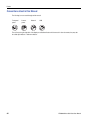
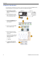

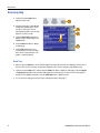

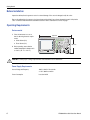
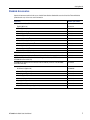
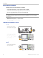
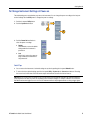
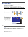
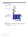
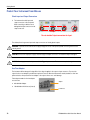


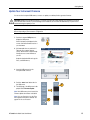

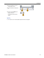
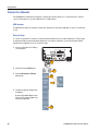
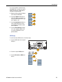
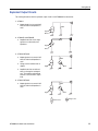
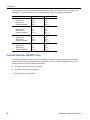
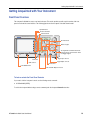
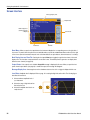
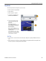


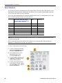
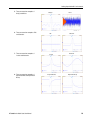
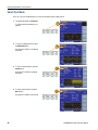
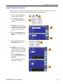
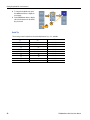
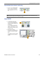
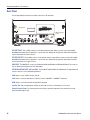

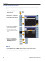
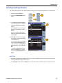

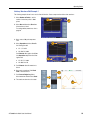
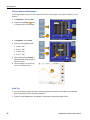
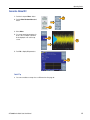
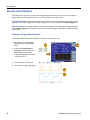
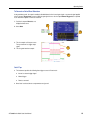
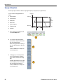
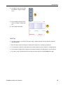


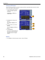
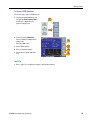
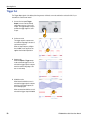


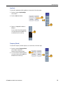
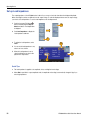
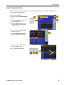
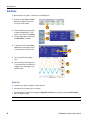


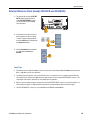
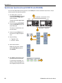
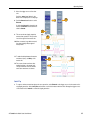

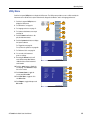
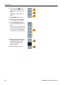
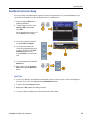
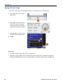
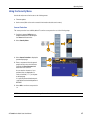
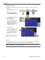

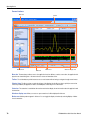
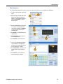
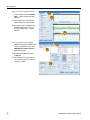


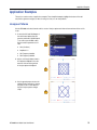
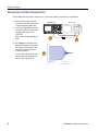


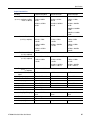
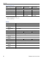
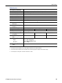

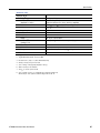
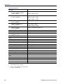

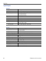
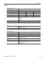


![[SOURce[1|2]]](http://vs1.manualzilla.com/store/data/005803287_1-72ff358839cd16ae2e8c94de56269657-150x150.png)
![[SOURce[1|2]]](http://vs1.manualzilla.com/store/data/006001849_1-f604f41c432649719bf8fb1e153f52f2-150x150.png)