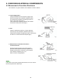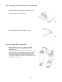
1
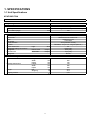
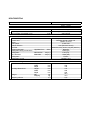
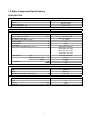
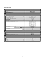
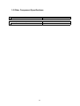
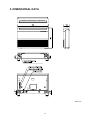
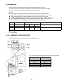
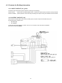
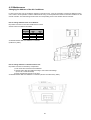
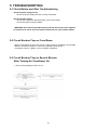
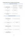
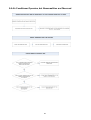
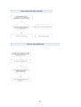
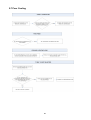
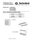
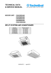
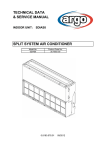
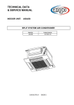
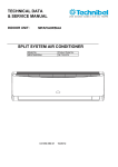
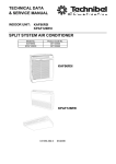
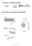
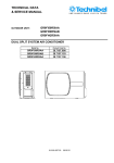
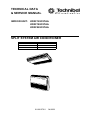
TECHNICAL DATA
& SERVICE MANUAL
INDOOR UNIT:
KPAF128C5TAA
KPAF188C5TAA
KPAF228C5TAA
SPLIT SYSTEM AIR CONDITIONER
Model No.
KPAF128C5TAA
KPAF188C5TAA
KPAF228C5TAA
Product Code No.
387105979
387105980
387105981
0.8180.570.0
04/2009
• Ground the unit following local electrical codes.
• The Yellow/Green wire cannot be used for any connection
different from the ground connection.
• Connect all wiring tightly. Loose wiring may cause overheating
at connection points and a possible fire hazard.
• Do not allow wiring to touch the refrigerant tubing, compressor,
or any moving parts of the fan.
• Do not use multi-core cable when wiring the power supply and
control lines. Use separate cables for each type of line.
IMPORTANT!
Please read before installation
This air conditioning system meets strict safety and operating
standards.
For the installer or service person, it is important to install or
service the system so that it operates safely and efficiently.
For safe installation and trouble-free operation, you must:
• Carefully read this instruction booklet before beginning.
• Follow each installation or repair step exactly as shown.
• Observe all local, state and national electrical codes.
• Pay close attention to all warning and caution notices given in
this manual.
•The unit must be supplied with a dedicated electrical line.
When transporting
Be careful when picking up and moving the indoor and outdoor
units. Get a partner to help, and bend your knees when lifting to
reduce strain on your back. Sharp edges or thin aluminium fins on
the air conditioner can cut your fingers.
WARNING
When installing...
This symbol refers to a hazard or unsafe practice which can result
in severe personal injury or death.
… In a ceiling
Make sure the ceiling is strong enough to hold the unit-weight.
It may be necessary to build a strong wooden or metal frame to
provide added support.
CAUTION
… In a room
Properly insulate any tubing run inside a room to prevent
"sweating", which can cause dripping and water damage to
walls and floors.
This symbol refers to a hazard or unsafe practice which can result
in personal injury or product or property damage.
... In moist or uneven locations
Use a raised concrete base to provide a solid level foundation
for the outdoor unit. This prevents damage and abnormal
vibrations.
If necessary, get help
These instructions are all you need for most installation sites and
maintenance conditions.
If you require help for a special problem, contact our sale/service
outlet or your certified dealer for additional instructions.
... In area with strong winds
Securely anchor the outdoor unit down with bolts and a metal
frame. Provide a suitable air baffle.
In case of improper installation
The manufacturer shall in no way be responsible for improper
installation or maintenance service, including failure to follow the
instructions in this document.
... In a snowy area (for heat pump-type systems)
Install the outdoor unit on a raised platform that is higher then
drifting snow. Provide snow vents.
SPECIAL PRECAUTIONS
When connecting refrigerant tubing
• During installation, connect before the refrigerant system and
then the wiring one; proceed in the reverse orden when removing
the units.
• Keep all tubing runs as short as possible.
• Use the flare method for connecting tubing.
• Apply refrigerant lubricant to the matching surfaces of the flare
and union tubes before connecting them; screw by hand and
then tighten the nut with a torque wrench for a leak-free
connection.
• Check carefully for leaks before starting the test run.
WARNING
When wiring
ELECTRICAL SHOCK CAN CAUSE SEVERE
PERSONAL INJURY OR DEATH. ONLY QUALIFIED,
EXPERIENCED ELECTRICIANS SHOULD ATTEMPT
TO WIRE THIS SYSTEM.
NOTE:
Depending on the system type, liquid and gas lines may be either
narrow or wide. Therefore, to avoid confusion, the refrigerant
tubing for your particular model is specified as narrow tube for
liquid, wide tube for gas.
• Do not supply power to the unit until all wiring and tubing are
completed or reconnected and checked, to ensure the grounding.
• Highly dangerous electrical voltages are used in this system.
Carefully refer to the wiring diagram and these instructions when
wiring.
Improper connections and inadequate grounding can cause
accidental injury and death.
When servicing
• Turn the power OFF at the main power board before opening
the unit to check or repair electrical parts and wiring.
• Keep your fingers and clothing away from any moving parts.
• Clean up the site after the work, remembering to check that no
metal scraps or bits of wiring have been left inside the unit being
serviced.
• Ventilate the room during the installation or testing the refrigeration
system; make sure that, after the installation, no gas leaks are
present, because this could produce toxic gas and dangerous
if in contact with flames or heat-sources.
2
Table of Contents
Page
1. SPECIFICATIONS
1-1 Unit specifications
1-2 Major Component specifications
1-3 Other Component specifications
4
4
7
10
2. DIMENSIONAL DATA
11
3. ELECTRICAL DATA
3-1 Electric Wiring Diagram
3-2 Wiring System Diagrams
12
12
13
4. FUNCTION
4-1 Cool Mode Operation
4-2 Dry Mode Operation
4-3 Fan Mode Operation
4-4 Auto Fan Speed
4-5 Forced Mode
4-6 Protection Operations in Cool and Dry Modes
4-7 I FEEL Function
4-8 NIGHT Function
4-9 Diagnostic
4-10 Jumpers Configuration
4-11 Contacts for Building Automation
4-12 Maintenance
14
14
15
15
15
16
16
17
17
18
18
19
20
5. TROUBLESHOOTING
5-1 Check before and after troubleshooting
5-2 Circuit Breaker Trips or Fuse Blows
5-3 Circuit Breaker in several minutes after turning air conditioner on
5-4 Unit and Compressor do not run
5-5 Some parts of the Air Conditioner do not operate
5-6 Air Conditioner operates, but abnormalities are observed
5-7 Poor Cooling
5-8 Excessive Cooling
5-9 If a Sensor is defective
21
21
21
21
22
23
24
26
27
27
6. CHECKING ELETRICAL COMPONENTS
6-1 Measurement of Insulation Resistance
6-2 Checking Continuity of Fuse on PCB Ass'y
6-3 Checking Motor Capacitor
28
28
29
29
3
1. SPECIFICATIONS
1-1 Unit Specifications
KPAF128C5TAA
Power source
220 - 240V ~ 50Hz
Voltage rating
230 V - 50 Hz
Performance
Capacity
Air circulation (High)
Features
Controls/Temperature controls
Control unit
Timer
Fan speed
Airflow direction
Air Filter
Power noise level
Refrigerant tubing connections
Refrigerant
tube diameter
Refrigerant
Dimensions & Weight
Unit dimensions
Package dimensions
Weight
m³/h
High
Narrow tube
Wide tube
dB-A
mm(in.)
mm(in.)
Height
Width
Depth
Height
Width
Depth
Net
Shipping
mm
mm
mm
mm
mm
mm
kg
kg
m3
Shipping volume
4
Cooling
See catalogue with the requested matching
700
Microprocessor/ I.C. thermostat
Wireless remote control unit
ON/OFF 24 hours
3 and Auto
Auto (Remote control)
Washable, easy acces, long life (2500 hr.)
55
Flare type
6,35 (1/4)
12,7 (1/2)
R410A
680
900
190
770
995
280
23,5
31,5
0,21
DATA SUBJECT TO CHANGE WITHOUT NOTICE
KPAF188C5TAA
Power source
220 - 240V ~ 50Hz
Voltage rating
230 V - 50 Hz
Performance
Capacity
Air circulation (High/Med./Low)
Features
Controls/Temperature controls
Control unit
Timer
Fan speed
Airflow direction
Air Filter
Power noise level
Refrigerant tubing connections
Refrigerant
tube diameter
Refrigerant
Refrigerant control
Dimensions & Weight
Unit dimensions
Package dimensions
Weight
m³/h
High/Med./Low
Narrow tube
Wide tube
dB-A
mm(in.)
mm(in.)
Height
Width
Depth
Height
Width
Depth
Net
Shipping
mm
mm
mm
mm
mm
mm
kg
kg
m3
Shipping volume
5
Cooling
See catalogue with the requested matching
720/615/515
Microprocessor/ I.C. thermostat
Wireless remote control unit
ON/OFF 24 hours
3 and Auto
Auto (Remote control)
Washable, easy acces, long life (2500 hr.)
56/52/47
Flare type
6,35 (1/4)
12,7 (1/2)
R410A
Capillary tube
680
900
190
770
995
280
23,5
31,5
0,21
DATA SUBJECT TO CHANGE WITHOUT NOTICE
KPAF228C5TAA
Power source
220 - 240V ~ 50Hz
Voltage rating
230 V - 50 Hz
Cooling
See catalogue with the requested matching
830/760/665
m³/h
Performance
Capacity
Air circulation (High/Med./Low)
Features
Controls/Temperature controls
Control unit
Timer
Fan speed
Airflow direction
Air Filter
Power noise level
Refrigerant tubing connections
Refrigerant
tube diameter
Refrigerant
Refrigerant control
Dimensions & Weight
Unit dimensions
Package dimensions
Weight
Shipping volume
Microprocessor/ I.C. thermostat
Wireless remote control unit
ON/OFF 24 hours
High/Med./Low
Narrow tube
Wide tube
Height
Width
Depth
Height
Width
Depth
Net
Shipping
dB-A
mm(in.)
mm(in.)
3 and Auto
Auto (Remote control)
Washable, easy acces, long life (2500 hr.)
60/57/54
Flare type
6,35 (1/4)
15,88 (5/8)
R410A
Capillary tube
680
mm
900
mm
190
mm
770
mm
995
mm
280
mm
23,5
kg
31,5
kg
3
0,21
m
DATA SUBJECT TO CHANGE WITHOUT NOTICE
1-2 Major Component Specifications
KPAF128C5TAA
Controller PCB
Part No.
Controls
Control circuit fuse
Jumper setting JP1..JP5
SAC ON-OFF IDU
Microprocessor
250 V - 3,15 A
2,54mm-5pcs
SAC W-REM
Remote Control Unit
Fan & Fan Motor
Type
Q'ty ……. Dia. and lenght
Fan motor model…Q'ty
No. of poles…rpm (230 V, High)
Nominal output
Running Amps
Power input
Coil resistance (Ambient temp. 25 °C )
Safety devices
mm
W
A
W
Ω
Type
Operating temp. Open
Close
°C
Run capacitor
µF
VAC
Flap Motor
Type
Model
Rating
Coil resistance (Ambient temp. 25 °C )
Ω
Heat Exch. Coil
Coil
Rows
Fin pitch
face area
Cross - flow
2…. Ø 130 / L 180
K48407-M01596…1
4…1160
21
0,29
65
GRY-WHT: 298÷343
WHT-PNK: 421÷485
WHT-VLT: 93,5÷108
VLT-ORG: 93,5÷108
ORG-YEL: 211÷243
Thermal protection
145 ± 5
Automatic
1.5
440
Stepping motor
MP24Z2
DC 12 V
400 ± 7%
Aluminium plate fin / Copper tube
2
1,5
mm
0,177
m2
DATA SUBJECT TO CHANGE WITHOUT NOTICE
7
KPAF188C5TAA
Controller PCB
Part No.
Controls
Control circuit fuse
Jumper setting JP1..JP5
SAC ON-OFF IDU
Microprocessor
250 V - 3,15 A
2,54mm-5pcs
Fan & Fan Motor
Type
Q'ty ……. Dia. and lenght
Fan motor model…Q'ty
No. of poles…rpm (230 V, High)
Nominal output
Running Amps
Power input
Coil resistance (Ambient temp. 25 °C )
Safety devices
mm
W
A
W
Ω
Type
Operating temp. Open
Close
°C
Run capacitor
µF
VAC
Flap Motor
Type
Model
Rating
Coil resistance (Ambient temp. 25 °C )
Ω
Heat Exch. Coil
Coil
Rows
Fin pitch
face area
Cross - flow
2…. Ø 130 / L 180
K48410-MO1597…1
4…1280
31,5
0,34
72
GRY-WHT:194÷223
WHT-PNK: 238÷274
WHT-VLT: 80,1÷ 92,2
VLT-ORG: 80,1÷92,2
ORG-YEL: 200÷230
Thermal protection
145 ± 5
Automatic
2,0
440
Stepping motor
MP24Z2
DC 12 V
400 ± 7%
Aluminium plate fin / Copper tube
2
1,8
mm
0,192
m2
DATA SUBJECT TO CHANGE WITHOUT NOTICE
8
KPAF228C5TAA
Controller PCB
Part No.
Controls
Control circuit fuse
Jumper setting JP1..JP5
SAC ON-OFF IDU
Microprocessor
250 V - 3,15 A
2,54mm-5pcs
Fan & Fan Motor
Type
Q'ty ……. Dia. and lenght
Fan motor model…Q'ty
No. of poles…rpm (230 V, High)
Nominal output
Running Amps
Power input
Coil resistance (Ambient temp. 25 °C )
Safety devices
Type
Operating temp. Open
Close
Run capacitor
Flap Motor
Type
Model
Rating
Coil resistance (Ambient temp. 25 °C )
Heat Exch. Coil
Coil
Rows
Fin pitch
face area
mm
W
A
W
Ω
°C
µF
VAC
Ω
Cross - flow
2…. Ø 130 / L 180
K48410-M01598…1
4…1370
35
0,35
74
GRY-WHT: 124÷144
WHT-PNK: 255÷294
WHT-VLT: 69,3÷79,8
VLT-ORG: 69,3÷79,8
ORG-YEL: 200÷233
Thermal protection
145 ± 5
Automatic
2,0
440
Stepping motor
MP24Z2
DC 12 V
400 ± 7%
Aluminium plate fin / Copper tube
2
1,8
mm
0,192
m2
DATA SUBJECT TO CHANGE WITHOUT NOTICE
1-3 Other Component Specifications
Thermistor ( Coil sensor TH1)
Resistance
ΚΩ
10 ± 3%
Thermistor ( Room sensor )
Resistance
kΩ
NTC-THERMISTOR
10 at 25 °C
10
2. DIMENSIONAL DATA
Units: mm
11
3. ELECTRICAL DATA
3-1 Electric Wiring Diagram
KPAF128C5TAA
KPAF188C5TAA
KPAF228C5TAA
12
3-2 Wiring System Diagram
KPAF128
GRF128L5
1-phase
KPAF188
3-phase
GRF188L5
model
GRF188L7
GRF228L7
KPAF188
KPAF228
A
power supply
B
control line
delayed fuse
m
mm2
m
mm2
GRF128
15
1,5
15
1,5
10 A
GRF188
15 (85 * )
1,5
16 A
25
2,5
GRF228
* 3 Phase version
15 (65 * )
20
4.FUNCTION
4-1 Cool Mode Operation
In Cooling Mode, the operation of the compressor (CM), Outdoor Fan (FMO) and Indoor Fan (FMI) are
determined by the difference between the room air temperature (RAT) and the set point temperature (SPT)
as shown in the graph.
NOTES
1. In this graph, the FMI is operating with the “Auto Fan Speed” setting. If the user has selected the Low,
Medium or High fan speed, the FMI will run constantly at that speed only.
2. In addition to the temperature difference of above, the operations of the main components (CM, FMO,
FMI) is also controlled by protection delays. That is: - the minimum off time of compressor is 3 minutes. - the minimum off time of compressor is 3 minutes. - the indoor fan can change speed only after it has operated at the same speed for 30 sec if in AUTO
and 1 sec for the other settings (High, Med, Low).
14
4-2 Dry Mode Operation
Dry operation remove moisture from indoor air running, in cooling mode, at a low level without reducing the
ambient temperature. This is done cycling ON and OFF indoor and outdoor units according to below.
ROOM
TEMP
DRY LEVEL
≥ SPT+2°C
LEVEL 0
< SPT+2°C
≥ SPT-1°C
< SPT-1°C
≥ 15°C
< 15°C
Operation according to COOLING mode
CM on
FMO on
FMI switches between L and LL (30 seconds)
RV off
CM switches 9 minutes off and 3 minutes on
LEVEL 2
FMO switches 9 minutes off and 3 minutes ON
FMI switches off and L during CM operation
RV off
CM off
DRY OFF ZONE FMO off
FMI off
RV off
LEVEL 1
SPT = Set Point Temperature
4-3 Fan Mode Operation
With this mode, the indoor fan is turned on while CM, FMO and RV stay off all the time. The user can select
between 3 speeds: HIGH, MEDIUM and LOW.
4-4 Auto Fan speed
With this option selected, the indoor fan speed changes automatically according to the difference between
the detected air temperature (RAT sensor) and the set point (SPT):
COOLING MODE
2 ≤ (RAT – SPT):
1 ≤ (RAT – SPT) < 2:
(RAT – SPT) < 1:
HIGH speed
MEDIUM speed
LOW speed
NOTE
SPT = Set Point Temperature
15
4-5 Forced Mode
In this mode the system operates (COOLING mode – fixed settings) or is switched off by means of
the MODE button of the indoor unit control board. The operation modes can be selected pressing
the button in a cyclic way (OFF ð COOL ð OFF…). The settings are:
SET POINT temperature = 25°C
FAN SPEED = HIGH
4-6 Protection operations in Cool and Dry Mode
This protection prevents ice formation on the indoor coil heat exchanger. The protection is activated by
the indoor coil temperature (ICT sensor) and only after 6 minutes of compressor operation. This
protection acts in 2 levels:
LEVEL 1
INDOOR FAN SPEED: ANY (as selected from remote controller)
COMPRESSOR: ON
OUTDOOR FAN: cycling (30 seconds ON B 30 seconds OFF).
LEVEL 2
INDOOR FAN SPEED: ANY (as selected from remote controller)
COMPRESSOR: OFF for at least 6 minutes and until ICT ≥ 8°C
OUTDOOR FAN: OFF for at least 6 minutes and until ICT ≥ 8°C
The system exit this protection routine when ICT temperature rises above 8°C.
16
4-7 I FEEL Function
As standard configuration the air conditioner operates detecting the room temperature through the sensor
equipped in the wireless remote controller (icon I FEEL shown on the display). This feature provides a
personalised environment since the temperature can be detected where the remote controller is located.
It is possible to de-activate this option pressing the I FEEL button on the remote controller.
In this case the I FEEL icon is no longer displayed and room temperature is detected through the sensor
included in the indoor unit.
4-8 NIGHT Function
When this function is active, room temperature changes automatically to compensate for body temperature
variations while sleeping. After 10 hours of operation system switches automatically to OFF state.
17
4-9 Diagnostic
With this feature is possible to have a visual signal that a trouble is occurring.
This mode is always active and the signalling is made through the display board LEDS .
In case of no troubles the LEDS status follows its normal function.
NOTES
The troubles are showed according a priority list that is in case of more than one
trouble present, is always showed, at first, the one with the highest priority (1 2 3 etc).
Sensor damaged means a situation where sensor is short-circuited or opened.
In case of damaged sensors, the system (CM, FMO, FMI etc), if in OFF state, does not start.
WRONG MODE SELECTED means a situation where the operating mode chosen with
remote controller does not comply with the one allowed by jumpers settings.
Priority
2
3
4
LEDS status
TROUBLE
RAT damaged
ICT damaged
WRONG MODE
SELECTED
O = LED off
z = LED on
F = LED blinking
Effects
LD1(stby)
LD2(opr)
LD3(timer)
F
F
F
O
F
F
O
O
F
System does not operate
System does not operate
4-10 JUMPERS CONFIGURATION
Jumpers are located on the indoor PCB near the MODE button.
Unit is shipped with jumpers set according to the following table:
18
JUMPER
STATUS
JP1
JP2
JP3
JP4
JP5
open
closed
open
closed
closed
4-11 Contacts for Building Automation
4-11.1 INPUT CONTACT (J4 - green)
The status of this input affects system operation according to the following:
Contact OPEN :
system does not operate (always OFF) – inputs from wireless remote controller are not processed
Contact CLOSED:
system operates in the normal way according to the inputs coming from wireless remote controller
4-11.2 OUTPUT CONTACT (J12)
This connector is directly tied to the contact (normally open) of a power relay which activates every time
the following alarm condition occur:
•
RAT damaged
•
ICT damaged
In this case when alarm happens, on poles 1 and 3 of J12 connector, 220 VAC-50Hz are available.
Max electrical load: 1A- 240VAC
19
4-12 Maintenance
Changing the Address of the Air Conditioner
In case of more than one air conditioner operating in the same room, it may be necessary to assign an address to each
unit in order to avoid operation conflicts. Address is set acting on the dip-switches located on the indoor PCB and on the
remote controller. The PCB settings must match the corresponding ones on the wireless remote controller.
How to change address of the air conditioner
Dip switch is located on the indoor PCB near the buzzer.
Set the PCB to the address desidered
UNIT
ADDRESS
1
2
3
4
SETTINGS
SW1
SW2
off
off
off
on
on
off
on
on
As default switches SW1 and SW2 are in off status
(PCB factory state).
How to change address on Remote Control Unit
Dip switch is located on the battery compartment.
1) Pull out the door and remove the batteries.
2) Set the switch SW1 and SW2 according to the indoor PCB settings
(do not act on SW3 and SW4)
3) Insert the batteries and pull on the door
As default switches SW1 and SW2 are in off status (remote controller factory state).
20
5. TROUBLESHOOTING
5-1 Check Before and After Troubleshooting
(A) Check power supply wiring.
• Check the power supply wires are correctly connected.
(B) Check power supply.
• Check that voltage is in specified range (±10% of the rating).
• Check that power is being supplied.
• WARNING: If the following troubleshooting must be done with power supplied,
be careful not to touch any uninsulated live part that can cause eletric shock
5-2 Circuit Breaker Trips or Fuse Blows
• When circuit breaker is set to ON, it trips in a few moments. Resetting is not possible.
• Measure insulation resistance. There is a possibility of ground fault.
If resistance value is 1 Mohm or less, insulation is defective.
5-3 Circuit Breaker Trips in Several Minutes
After Turning Air Conditioner On
1 • There is the possibility of short circuit.
21
2 • The unit does not run.
5-4 Unit and Compressor Do Not Run
The unit does not run when air conditioner is in the follwing conditions:
• When the room temperature is below the setting temperature.
• During the protection modes.
22
5-5 Some Parts of the Air Conditioner Do Not Operate
23
5-6 Air Conditioner Operates, but Abnormalities are Observed
24
25
5-7 Poor Cooling
26
5-8 Excessive Cooling
5-9 A Sensor Is Defective
27
6. CHECKING ELETRICAL COMPONENTS
6-1 Measurement of Insulation Resistance
The insulation is in good condition if the resistance exceeds 1 MOhm
a) Power Supply Wires
Clamp the earthed wire of the power supply wires
with the lead clip of the insulation resistance tester
and measure the resistance by placing a probe on
either of the power wires (fig.1).
Then measure the resistance between the earthed
wire and the other power wires (fig.1).
b) Unit
Clamp an alluminium plate fin or copper tube with
the lead clip of the insulation resistance tester and
measure the resistance by placing a probe on N terminal,
and then on Lterminal the terminal plate (fig.2)
c) Measurement of Insulation Resistance
for Electrical Parts
Disconnect the lead wires of the disired electric
part from terminal plate, PCB assy, capacitor, etc.
Similary disconnect the connector. Then measure
the insulation resistance (fig.1 to 4).
Refer to electric wiring diagram.
NOTE
If the probe cannot enter the poles because the hole is too narrow
then use a probe with a thinner pin.
28
6-2 Checking Continuity of fuse on PCB assy
Remove PCB assy from electrical component box (fig.5)
Then pull out the fuse from PCB assy
Check continuity of fuse by the multimeter (fig.6)
6-3 Checking Motor Capacitor
Remove the lead wires from the capacitor terminals,
and then place a probe on the capacitor terminals
as shown in fig.7.
Observe the deflection of the pointer, setting the resistance
measuring range of the multimeter to the maximum value.
The capacitor is "good" if the pointer bounces to a great
extent and the gradually returns to its original position.
The range of deflection and deflection time deffer according
to capacity of the capacitor.
29
R.D. 28 Reyrieux BP 131 - 01601 Trévoux CEDEX France
Tél. 04.74.00.92.92 - Fax 04.74.00.42.00
R.C.S. Bourg-en-Bresse B 759 200 728