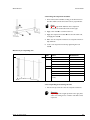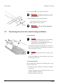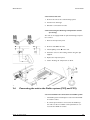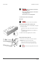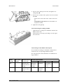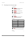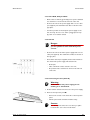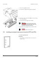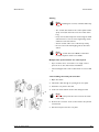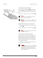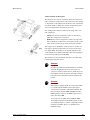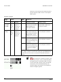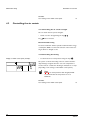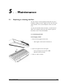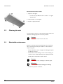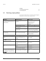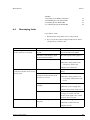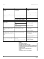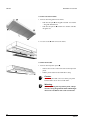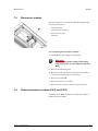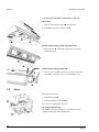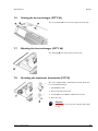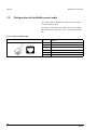
1
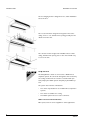
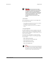
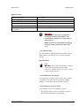
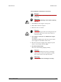
Manual
Comfort air curtain
Model CITY - CYV - CYQ
Version of Guide: 5.0
Original manual
a
R
COMFORT AIR CURTAIN
. . . Table of contents
1
2
Introduction
4
1.1
1.2
1.3
1.4
4
4
5
10
Installation
2.1
2.2
2.3
2.4
2.5
2.6
2.7
2.8
2.9
2.10
2.11
3
Safety instructions
Checking for faults
Resolving simple problems
Remedying faults
Service
7.1
2
Replacing or cleaning the filter
Cleaning the unit
Scheduled maintenance
Faults
6.1
6.2
6.3
6.4
7
Switching the unit ON and OFF
Controlling the air curtain
Maintenance
5.1
5.2
5.3
6
Switching the unit ON and OFF
Setting the fan speed
Setting the heating (CITY E and CYV)
Operation CYQ
4.1
4.2
5
Safety instructions
Delivery check
General working method
Fixing the unit
Connecting the unit to the central heating installation
Connecting the unit to the Daikin system (CYQ and CYV)
Connecting the unit to the power supply
Installing control panel and external controls (CITY and CYV)
Control system without touch pad controller (CITY and CYV)
Finishing the unit
Switching on and checking function
Operation CITY and CYV
3.1
3.2
3.3
4
About this manual
How to read this manual
About the unit
Safety instructions
Safety instructions
12
12
12
12
14
16
17
20
22
27
29
33
35
35
35
36
37
37
38
39
39
40
40
41
41
41
42
43
45
45
7.2
7.3
7.4
7.5
7.6
7.7
7.8
7.9
8
Access to the interior of the unit
Electronics module
Daikin electronics module (CYQ and CYV)
Fuses
Venting the heat exchanger (CITY W)
Bleeding the heat exchanger (CITY W)
Resetting the maximum thermostat (CITY E)
Configuration of the Biddle control cable
Dismantling
Versie: 5.0 (04-06-2012)
45
47
47
48
49
49
49
50
51
3
1 . . Introduction
1.1
About this manual
This manual describes the installation, operation and maintenance of the comfort air curtain model CITY, CYQ, CYV. The
manual also provides instructions and information on service
operations.
1.2
How to read this manual
1.2.1 For CYQ and CYV only:
This manual makes cross-reference to the manuals of the Daikin components (outdoor unit, indoor unit, control panel,
etc.).
1.2.2 Marginal symbols used in the manual
The following symbols are used in this manual:
n
Note:
c
Caution:
Draws your attention to an important part of the
text.
If you do not perform this procedure or action
correctly, you may damage the unit.
Follow the instructions strictly.
w
Warning:
If you do not perform this procedure or
action correctly, you may cause damage and/
or bodily injury.
Follow the instructions strictly.
Versie: 5.0 (04-06-2012)
4
CITY MANUAL
INTRODUCTION
d
Danger:
This indicates actions which are not
permitted.
Ignoring this warning may lead to serious
damage or accidents which may involve bodily injury.
1.2.3 Pictograms used on the unit and in the manual
The following pictograms indicate potential risks or hazards.
The same pictograms will also be found on the unit.
Pictograms
PICTOGRAM
DESCRIPTION
w
You are entering an area of the unit containing live components.
Accessible to qualified maintenance staff only.
Exercise caution.
w
This surface or part can be hot. There is a risk of burns on contact.
1.2.4 Related documentation
In addition to this manual, the following document has been
supplied with the unit:
•
1.3
Wiring diagram for installation and service
About the unit
1.3.1 Applications
The comfort air curtain is intended for the separation of climates between two rooms, and for heating and filtering (filter
class EN779-G2) of air. The unit is installed above the doorway, across its full width.
Versie: 5.0 (04-06-2012)
5
INTRODUCTION
COMFORT AIR CURTAIN
The free-hanging model is designed for free, visible installation
above the door.
The recessed model is designed for integration into a false
ceiling or into a cove, with the inlet opening possibly at some
distance from the unit.
The cassette model is designed for installation above a false
ceiling, with the inlet opening close to the unit and with easy
access to the unit.
CYQ and CYV
The CYQ/CYV air curtain is connected to a Daikin direct
expansion system. The air blown through the unit is heated by
the cooling medium. The air curtain is controlled and operated partly by the Daikin system and partly by the Biddle system.
The system has a number of limitations:
•
The unit is only suitable for use in Daikin direct expansion
systems.
•
The unit is not suitable for cooling.
•
The Daikin system has to be active at all times.
Other versions and intended use.
On request, versions can be supplied for other applications.
6
CITY MANUAL
INTRODUCTION
w
Warning:
Applications other than those described
above are not considered to be an intended
use. Biddle assumes no responsibility for
damage or injury resulting from applications
other than the intended use. The intended
use also implies observance of and
compliance with the instructions in this
manual.
1.3.2 Function
The air curtain blows out a warm air stream straight down,
thus achieving the following:
•
The exchange of air between two rooms due to temperature differences (convection) is stopped.
•
The cold air entering across the floor due to draught is
heated.
1.3.3 Type designation
The table below gives an overview of available models of the
comfort air curtain and the corresponding type designations.
Combined, the type designations constitute the type code, for
instance: CITY S-100-W-F.
If some part of the manual applies to certain models only,
these will be indicated using the corresponding type designation, for example:
•
CITY S: Models with capacity S
•
CITY 100: Models with discharge width 100
•
CITY W: Water-heated models
•
CITY E: Electrically-heated models
•
CITY F: Free-hanging models
n
Versie: 5.0 (04-06-2012)
Note:
For the illustrations in this manual, the following unit
type is used as a general example: CITY M-150-W-F.
The appearance of your unit may be different but its
function is the same, unless stated otherwise.
7
INTRODUCTION
COMFORT AIR CURTAIN
Explanation of the type code
PART TYPE CODE
DESIGNATION
MEANING
Product series
CITY, CYQ, CYV
General designation for the series
CYV
For connection to Daikin VRV system (‘multi’)
CYQ
For connection to Daikin ERQ system (‘pair’)
Capacity
S, M or L
Small, medium or large range
Discharge width
100, 150, 200 or 250
Discharge width in cm
Heating
W
Water heating
E
Electric heating
A
Without heating
DK
Heating with Daikin direct expansion system
F
Free-hanging model
R
Recessed model
C
Cassette model
B
White
S
Aluminium
X
Non-standard colour
C
Touch pad controller included
N
Not included (if several units are connected in one installation)
Mounting method
Colour (CYQ and CYV
only)
Control panel (CYQ
and CYV only)
1.3.4 Type plate
The type plate is located on the front left of the unit.
This manual refers to the following data on the type plate:
•
Type: Complete type code of the unit
•
M: Weight of the unit
•
Medium: Heating medium
•
Capacity index: Daikin capacity index
•
P max: Maximum permissible working pressure of the hot
water circuit (at 230ºF / 110 °C).
•
U, Imax, Pmotor and Pheating: Maximum load on the electrical
system by the unit
1.3.5 Field of application
The comfort air curtain is predominantly used in commercial
premises at an ambient temperature of max. 40°C. The following limits must thereby be observed:
8
CITY MANUAL
INTRODUCTION
Application limits
Ambient temperature
5°C to 40°C
System voltage
see type plate
Power
see type plate
Maximum discharge temperature
50°C
Heating medium CITY W
water with max. 20% glycol
Maximum working pressure and temperature CITY W
6 bar at 110°C
w
Warning:
The air curtain must not be employed in
potentially explosive atmospheres, wet
environments, outdoors or in very dusty or
aggressive air.
Biddle assumes no responsibility for damage
or injury resulting from use in these situations.
1.3.6 CE declaration
The unit satisfies the applicable CE standards. The complete
CE Declaration of Conformity can be found at: www.biddle.info.
Class A product
n
Note:
CYV only: This is a Class A product. In a domestic
environment, this product may cause radio
interference in which case the user may be required
to take adequate measures.
1.3.7 Modifications and changes
No modifications or changes may be made to the unit which
could influence its safety without the approval of Biddle.
Changes or modifications will void the CE declaration.
1.3.8 Components and accessories
The following accessories are available as options:
•
Versie: 5.0 (04-06-2012)
Control panel (able to control a maximum of 10 units)
(CITY, standard with CYV, not with CYQ)
9
INTRODUCTION
COMFORT AIR CURTAIN
•
Biddle control cable, available in various lengths
•
Discharge temperature control unit (CITY W only)
•
Door contact switch
•
Set of wall brackets
n
Note:
The unit can also be operated without control panel.
For CYQ and CYV only: Daikin components
The following Daikin components are required for an installation:
•
Outdoor unit
•
Optional: One or more indoor units
•
Daikin control panel (optional for CYV)
•
Connection materials, such as cooling lines, wiring, etc.:
See the installation manual for the outdoor unit.
c
1.4
Caution:
The control system and the capacity index of the
Daikin outdoor unit must correspond to those of
the Biddle air curtain.
Safety instructions
1.4.1 Operation
10
w
Warning:
w
w
Warning:
c
Caution:
Do not put any objects in the inlets and
outlets.
Do not block the inlets and outlets.
Warning:
The upper surface of the unit becomes hot
during operation.
In exceptional situations, water may run out of the
unit. Therefore do not place anything under the unit
that could be damaged as a result.
CITY MANUAL
INTRODUCTION
1.4.2 Installation, maintenance and service
d
w
Danger:
The unit may be opened by qualified technical
staff only.
Warning:
Perform the following actions before opening
the unit:
1. Switch OFF the unit using the control panel.
2. Wait until the fans have stopped.
3. Allow the unit to cool down.
c
Caution:
The heat exchanger and/or the heating elements can
get very hot. Moreover, the fans may continue to
rotate for a while.
4. For models for connection to a Daikin direct expansion system:
Switch OFF the Daikin system and disconnect the mains
power supply from the Daikin outdoor unit.
5. Disconnect the power supply (remove plug from power
point or move isolation switch to OFF).
6. For water-heated models:
Close the central heating supply (if possible).
Versie: 5.0 (04-06-2012)
c
Caution:
w
Warning:
For CYQ and CYV: If the system is operating in
defrost mode or has been in operation recently,
there may be water in the inspection panel.
The fins of the heat exchanger are sharp.
11
2 . . Installation
2.1
Safety instructions
w
Warning:
w
Warning:
Installation work on the unit may only be
performed by qualified technical staff.
Before you begin: read the safety instructions.
See also:
1.4 Safety instructions
2.2
2.3
10
Delivery check
•
Check the unit and its packaging for correct delivery.
Immediately report to the driver and to the supplier any
damage caused in transit.
•
Make sure that all components and accompanying parts
have been supplied. Immediately report any defects to the
supplier.
General working method
2.3.1 Sequence of operations
Biddle recommends the following working method for installing the Comfort Air Curtain:
1. Suspend the unit.
2. For water-heated models:
Connect the unit to the central heating system.
For models for connection to a Daikin direct expansion system:
Install the Daikin components as described in the respective installation manuals.
-
Versie: 5.0 (04-06-2012)
Outdoor unit;
If installed in your system: Indoor unit(s);
12
CITY MANUAL
INSTALLATION
-
Control panel.
3. Connect the unit to the mains power supply.
4. Install the control panel and (any optional) connections to
external controls.
5. Finish the unit.
6. For models for connection to a Daikin direct expansion system:
Connect the air curtain unit to the Daikin system.
7. Turn on the power supply and check the working of the
unit.
General instructions
Some parts of this section are applicable only to certain models. Where this is the case, it will be indicated. If no specific
model is referred to, the description applies to all models.
n
Note:
Make sure you perform all installation operations
that are required for your unit.
Check the type plate and consult the manual if you
are not sure about the model or type of your unit.
n
Note:
Protect the unit from damage and ingress of dust,
cement, etc. throughout the installation. You can, for
instance, use the packaging for protection.
See also:
2.4 Fixing the unit
14
2.5 Connecting the unit to the central heating installation
16
2.6 Connecting the unit to the Daikin system (CYQ and CYV)
17
2.7 Connecting the unit to the power supply
20
2.8 Installing control panel and external controls (CITY and CYV) 22
2.9 Control system without touch pad controller (CITY and CYV) 27
2.10 Finishing the unit
29
2.11 Switching on and checking function
33
Versie: 5.0 (04-06-2012)
13
INSTALLATION
2.4
COMFORT AIR CURTAIN
Fixing the unit
2.4.1 Determining the location of the unit
d
Danger:
Do not install the unit in a vertical position.
•
Make sure that the structure from which the unit is about
to be suspended can bear the weight of the unit. The
weight is specified on the type plate.
•
Note the following dimensions:
-
The unit must be at least as wide as the doorway
(dimension b).
Position the unit as near to the doorway as possible.
The maximum mounting height of the unit (dimension
h, measured from the floor to the discharge grille)
depends on the unit type.
Installation height of unit
MAXIMUM INSTALLATION
TYPE
HEIGHT
CITY S
2.3 m
CITY M
2.5 m
CITY L
3.0 m
These heights apply only under normal circumstances. If in
doubt, ask Biddle for advice on the correct height.
w
w
Warning:
The minimum mounting height (dimension h)
is 1.8 m.
Warning:
The top of the unit may get hot. Mount the
unit with a minimum clearance of 25 mm
from the ceiling (dimension x).
See also:
1.3.4 Type plate
14
8
CITY MANUAL
INSTALLATION
2.4.2 Fixing the suspension brackets
1. Fix four threaded rods M8 according to the dimensions in
the table. Make sure the threaded rods are perpendicular.
n
Note:
Units of type CITY 250 have three suspension
brackets. Fix six threaded rods for that type.
2. Apply a lock nut 1 to each threaded rod.
3. Apply the suspension brackets 2 onto the threaded rods,
and apply the nuts 3.
4. Make sure the suspension brackets are suspended horizontally and flush.
5. Secure each suspension bracket by tightening the lock
nut 1.
Dimensions for suspending unit
SIZE
TYPE
DIMENSIONS
a
all models
as needed
b
CITY S
119 mm
CITY M
119 mm
CITY L
200 mm
c
all models
200 mm
d
CITY 100
500 mm
CITY 150
1000 mm
CITY 200
1500 mm
CITY 250 (six threaded
rods)
2 x 1000 mm
2.4.3 Suspending and securing the unit
1. Lift the unit up and hook it into the suspension brackets.
c
Versie: 5.0 (04-06-2012)
Caution:
Depending on the weight specified on the type plate,
either use a lifting device or lift the unit with at least
2 persons.
15
INSTALLATION
COMFORT AIR CURTAIN
2. Fit a lock plate 3 to each suspension bracket.
w
Warning:
The unit may fall down if you do not secure
the suspension.
3. Check whether the unit is suspended firmly:
-
w
2.5
Try to push the unit from its suspension.
Shake the unit for a few seconds.
Warning:
Ensure you do not run any risk, should the
unit drop down.
Connecting the unit to the central heating installation
2.5.1 Particulars
c
•
The supply and return pipes of the central heating
system must be connected to the correct
corresponding connections 1. The directions are
indicated on the unit using arrows.
The maximum permissible operating pressure of the hot
water circuit is specified on the type plate. It is based on a
water temperature of 110°C.
c
•
Caution:
Caution:
Biddle recommends the inclusion of a valve in each
pipe.
The bleed valve 2 of the heat exchanger is located at the
left in the top of the unit.
2.5.2 Frost protection
Take the following precautions if you install the unit in a room
where frost may occur:
16
•
Provide for constant circulation of the water at the right
temperature;
•
Add up to 20% glycol to the water when the unit is not in
operation during the wintertime;
•
Or drain the system and the unit.
CITY MANUAL
INSTALLATION
2.5.3 Connect the unit
1. Connect the unit to the central heating system.
2. Vent the heat exchanger.
3. Check the connections for leaks.
2.5.4 Connecting the discharge temperature control
(accessory)
The unit can be equipped with an optional discharge temperature control.
1. Remove the inspection panel.
2. Connect valve 1 to the unit.
3. Install capillary sensor 2 in the unit.
4. Fasten the sensor to the heating element using the clips
supplied.
5. Replace the inspection panel.
6. Set the discharge air temperature to 35°C.
2.6
Connecting the unit to the Daikin system (CYQ and CYV)
2.6.1 Preconditions for connection to a Daikin system
Versie: 5.0 (04-06-2012)
•
The Daikin system must always be active when the Biddle
air curtain is active.
•
A control system must be connected to the Daikin system. This can also be a Daikin control panel that is connected to the Biddle air curtain.
17
INSTALLATION
COMFORT AIR CURTAIN
w
Warning:
Units of type CYV may only be connected to
a Daikin VRV system.
Units of type CYQ may only be connected to
a Daikin ERQ system.
These units are not interchangeable.
2.6.2 Connection of the control system
All models
c
Caution:
Use cable with a cross-section of min. 0.75 mm².
Models with discharge width 150, 200 or 250
1. Connect the system control to terminal X84 on the upper
side of the air curtain:
-
Connect the control cable of the outdoor unit to F1/
F2.
If installed on your unit: Connect the Daikin control panel to P1/P2.
2. Install the cable sheath (supplied) on the terminal.
Models with discharge width 100
1. Remove the cover of the box on the side of the unit.
2. Optional: Remove the box from the unit:
-
n
18
Remove the bracket from the unit and the box.
Install the box on the wall at an appropriate point.
Note:
Do not disconnect the wiring between the box and
the unit.
CITY MANUAL
INSTALLATION
3. Lay the control cable(s) into the box, through the free
cable gland(s) 3.
4. Connect the controller of the system to the free terminal
block 4:
-
Connect the control cable of the outdoor unit to F1/
F2.
If installed on your unit: Connect the Daikin control panel to P1/P2.
5. Tighten the cable gland(s).
2.6.3 Connecting the cooling medium
•
Install the lines according to the installation manual of the
Daikin outdoor unit.
•
Solder the lines to the pipes protruding out of the upper
side of the unit.
2.6.4 Settings on the Daikin control panel
You can make local settings on the Daikin control panel as
described in the corresponding installation manual.
The units described in this manual have a few additional setting possibilities:
SECOND CODE NUMBER
MODE
FIRST CODE
DESCRIPTION OF
NUMBER
NUMBER
THE SETTING
01
02
03
04
(22)
3
Function of air
curtain when not
heating
unheated
(standard
setting)
unheated
at standstill
(if 23-8 is set
to 01)
--
(23)
8
Function of air
curtain in defrost
mode
at standstill
unheated
(standard
setting)
unheated
--
Versie: 5.0 (04-06-2012)
19
INSTALLATION
2.7
COMFORT AIR CURTAIN
Connecting the unit to the power supply
2.7.1 All models
w
Warning:
w
w
Warning:
Do not turn on the unit from the power
supply. Use the control panel.
The unit must be earthed (grounded).
Warning:
Connect the unit in accordance with the
applicable local requirements.
2.7.2 Fuse ratings
w
Warning:
Every unit must be separately fused in
accordance with the table below.
Fuse ratings
MAXIMUM AMPERAGE ON MAXIMUM FUSE RATING A
TYPE PLATE L1, L2 OR L3
<= 10 A
16 A
<= 15 A
20 A
<= 20 A
25 A
<= 25 A
35 A
<= 35 A
50 A
<= 50 A
63 A
<= 65 A
80 A
<= 80 A
100 A
<= 102 A
125 A
n
Note:
Multiple units may only be served by a common fuse
if their total current consumption is less than 10 A.
See also:
1.3.4 Type plate
20
8
CITY MANUAL
INSTALLATION
2.7.3 CITY W/A, CYQ and CYV
•
Ensure that an earthed (grounded) power point is available
at a maximum of 1.5 m from the left side of the unit.
•
Connect the unit to the power supply with a 3-core cable
(not supplied). The maximum load data are shown on the
type plate.
•
It must be possible to interrupt the power supply to the
unit. You may choose to use either a plugged power supply cable or an isolation switch.
2.7.4 CITY-E
d
Danger:
Do not perform the connection work unless
you are qualified to work with three-phase
current.
•
Connect the unit to the mains power supply with a 5-core
cable (not supplied). The maximum load data are shown on
the type plate.
•
An isolation switch (not supplied) must be fitted between
the unit and the power supply. This switch must:
-
Be all-pole,
Have a minimum contact clearance of 3 mm,
Be positioned at a maximum of 4 m from the left side
of the unit.
2.7.5 Connecting the unit (CITY E)
w
Warning:
Make sure that the power supply you are
working on is switched off.
1. Fit the isolation switch and connect it to the power supply.
2. Remove the inspection panel 1:
-
Remove the screws on the front side of the inspection
panel.
Pull the panel a little forward and take it away.
c
Versie: 5.0 (04-06-2012)
Caution:
The whole panel will come loose when you pull it
forward: Take care it does not fall down.
21
INSTALLATION
COMFORT AIR CURTAIN
3. Fix the cable gland 2 to the unit.
4. Lead the power supply cable through the cable gland.
5. Connect the cable to the terminal 3 in the unit according
to the wiring diagram.
6. Fit the inspection panel again and screw tight.
w
Warning:
Always secure the inspection panel using
flanged bolts with milled edges: These are
needed for the earth connection.
7. Connect the power supply cable to the isolation switch.
c
2.8
Caution:
Do not yet switch the mains supply on.
Installing control panel and external controls (CITY and CYV)
2.8.1 Control panel details
Positioning
•
22
You may fix the control panel either to the wall or to a
standard socket.
CITY MANUAL
INSTALLATION
Cabling
n
Note:
Take the following into account, otherwise faults may
occur:
- The control cable between the control panel and the
(first) connected unit must not be more than 50 m
long.
- Keep control cables away from electromagnetic fields
and interference sources such as high-voltage cables
and fluorescent tube starters.
- Stretch control cables out or roll them up neatly.
- Do not remove the dummy plug, unless otherwise
stated.
n
Note:
Use only control cables from Biddle. A standard
modular telephone cable is not suitable.
Multiple units operated from one control panel
•
Up to 10 units can be connected to one single control
panel. To do so, the units must be interlinked.
•
The total length of the control cables must not exceed 100
m.
2.8.2 Installing the touch pad controller
1. Open the switch
2. Thread the cable through an opening in the rear panel.
3. Fasten the rear panel to the wall.
4. Secure the cable with the strain relief clamp provided.
n
Note:
The cable must protrude some9 cm from the strain
relief clamp.
5. Connect the connector of the control cable to the printed
circuit board.
6. Put the front panel onto the rear plate.
Versie: 5.0 (04-06-2012)
23
INSTALLATION
COMFORT AIR CURTAIN
2.8.3 Connecting control panel to unit
The control panel connections G and E are located on the
connector plate 3 on the upper side of the unit. The two
sockets are identical. One of the two sockets has a dummy
plug.
1. Connect the control cable to the free terminal G or E.
n
Note:
n
Note:
Do not remove the dummy plug from the other
socket, as this may lead to faults.
Leave approx. 30 cm of free cable length: It will be
needed to take the electronics out when servicing
the unit.
Multiple units operated from one control panel
1. For each unit to be linked, remove the dummy plug from
socket G or E.
2. Link the units: Connect the control cables to G and E.
n
Note:
Do not remove the dummy plug from the last unit,
as this may lead to faults.
2.8.4 Connecting external controls (option)
The connector plate on the upper side of the unit has three
inputs (X72) for the connection of external controls. The
inputs can be used to change the mode of operation of the
unit without the intervention of the user. The inputs can be
used for connection of e.g. a timer clock, a contact thermostat or a GBS-controlled relay.
1. Connect the cable for the external controls (if used) to
the terminals on the connector plate.
c
24
Caution:
The input is designed for controls with potential free
contacts. Biddle recommends the use of components
with gold-plated contacts and a low resistance.
Preferably lower than 20 mΩ in order to be able to
switch 1 mA at 5 VDC.
CITY MANUAL
INSTALLATION
2.8.5 Functions of the inputs
The functions of a control component depends on the terminals to which the component is connected and on the settings
on the interface. The table below shows for each control function the terminals to which the control component has to be
connected and how the interface has to be set.
The setting on the interface relates to the range of the control component:
•
Local: The control component is active on the unit to
which the component is connected
•
Global: The control component is active not only on the
unit to which the component is connected, but also on all
other units connected to the same touch pad controller
The range is set as standard to local. In order to set the control range to global, a jumper has to be moved on the interface (block X64). The jumper to be moved depends on the
control function (see table below). Place the removed jumper
in the reserve positions provided (X65).
The interface is located inside the unit and is accessible after
removing the inspection panel.
c
Caution:
c
Caution:
For CITY:
A jumper is installed as standard between terminals
T and G. This jumper has to be removed if you
connect a control component to T and G. If you do
not install a control component, the jumper must be
left in place: The unit will not function without the
jumper.
For CYV:
CYV units are equipped with an release relay which
is controlled by the Daikin system. This relay is
connected to terminals T and G of block X72. The
unit can only be switched ON and OFF when the
Daikin system is active. If the Daikin system is not
active, the unit is OFF
You can choose to switch the unit ON and OFF
externally irrespective of the Daikin system. In this
case install a jumper or control component between
terminals T and G in place of or parallel to the
standard wiring.
Versie: 5.0 (04-06-2012)
25
INSTALLATION
COMFORT AIR CURTAIN
Contacts on the terminals of block X72 only have a
function when the enable contact is closed by the
Daikin system.
Functions of inputs
FUNCTION
TERMI-
RANGE
NAL
LOCAL
GLOBAL
Switching
unit ON
and OFF
No setting
necessary
Remove
jumper 6
from block
64 on the
interface.
Change
setting.
No setting
necessary
Remove
jumper 5
from block
64 on the
interface.
FUNCTION
CONTACT CLOSED
CONTACT OPEN
T and G
The unit is in stand-by.
The unit can be switched
ON and OFF via the
touch pad controller.
The unit is OFF and cannot be
switched ON or OFF via the
touch pad controller.
D and G
The unit operates 1 level
higher than indicated by
the touch pad controller.
On CITY E the electric
heating is also increased.
The unit operates as indicated
by the touch pad controller.
P and G
The unit operates at the
highest level. On CITY E
the electric heating is not
increased.
The unit operates as indicated
by the touch pad controller.
D, P and
G
The unit operates at the
highest level. On CITY E
the electric heating is also
switched to the highest
level.
The unit operates as indicated
by the touch pad controller.
Caution: If the electric heating never has to be switched up at the same
time, jumper 4 must be removed. This setting has only a local function
and therefore has to be made on each unit for which this function is
desired.
n
26
Note:
The functions which use terminals P and G are only
available from interface version V4.0 Rev.06 (IC10).
The global range for terminals P and G can only be
set from touch pad controller version V2.1 Rev.02
and interface version V4.0 Rev.07 (IC10). The
standard settings of the jumpers on block X64 are
shown in the figure opposite.
CITY MANUAL
INSTALLATION
2.8.6 Unit output (CYV)
CYV units are equipped with an additional output X83 on the
unit. The contact to this output is disconnected when the unit
is on.
This output can be used, for example, for a function signal.
2.8.7 Initialising the touch pad controller
In order to inform the touch pad controller how many units
are connected, it has to be initialised. Initialisation has to be
performed in the following situations:
•
Before putting the unit into operation.
•
After connection of additional units to the touch pad controller.
•
For checking the control cable.
1. Press keys :], and [ simultaneously.
2. Wait 10 seconds. The LEDs of keys ] and [ start to
flash.
3. Wait 2 minutes. The LED of key : starts to flash. The
number of flashes of the LED corresponds to the number
of units connected to the touch pad controller.
The unit is now ready for operation.
2.9
Control system without touch pad controller (CITY and CYV)
The unit can be controlled using control components such as a
GBS-controlled relay, a room thermostat, a timer or a door
contact switch. The standard Biddle touch pad controller is
then not necessary.
It is not possible to set the heating power separately from the
fan speed on the following units:
•
CITY-E
•
CYV
If separate control of the electric heating power is nevertheless required, we recommend the use of a power controller
(e.g.: Kimsafe).
Versie: 5.0 (04-06-2012)
27
INSTALLATION
COMFORT AIR CURTAIN
2.9.1 Modifying the interface
In order to adapt the unit for operation without touch pad
controller, the interface has to be modified. This is done by
removing jumpers 1 and 2 from block X64 on the interface.
1. Switch OFF the power supply.
2. Open the unit (see also the unit operating manual).
3. Move jumpers 1 and 2 to the reserve positions (X65)
4. Close the unit.
2.9.2 Connection of control components
c
Caution:
c
Caution:
Control components must be connected to block
X72 of the connector plate on the outside of the
unit.
Control components must switch with potential free
contacts. Biddle recommends the use of components
with gold-plated contacts and a low resistance.
Preferably lower than 20 mΩ in order to be able to
switch 1 mA at 5 VDC.
The control components can activate four functions:
•
Switching the unit off (OFF)
•
Switching the unit to low speed (1)
•
Switching the unit to medium speed (2)
•
Switching the unit to high speed (3)
A function is activated when a control component makes a
contact between the connected terminals as shown in the figure. Follow the instructions below to employ one or more
functions:
28
CITY MANUAL
INSTALLATION
1. Select a control function.
2. Connect the control component to the corresponding terminals P, D, T or G of block X72. Use the circuit diagram
opposite.
3. Repeat steps 1 and 2 for each additional component.
4. Connect the unit to the mains power supply. The control
system is now ready for use.
If you wish to connect several units (max. 10) to 1 control
component, the wiring at the terminals has to be connected
through between the units.
2.10
Finishing the unit
2.10.1 Finishing free-hanging models
Fitting inlet grilles
1. Fit the inlet grilles to the unit:
-
Hook the grilles onto the upper side of the unit.
The back of each grille has a projection. Fit the grille
with this projection in the rectangular hole .
2.10.2 Finishing recessed models
General
n
Note:
Ensure that the unit remains accessible for
maintenance and repair through, for instance, an
inspection hatch.
Adjusting the discharge duct
If installing two or more units alongside one another, you must
adjust the discharge duct so that the finishing edges are not in
each other’s way.
1. Remove the end piece with finishing edge 1.
Versie: 5.0 (04-06-2012)
29
INSTALLATION
COMFORT AIR CURTAIN
2. Install the end piece without finishing edge 2.
Installing the discharge duct
1. Make a hole in the ceiling for the discharge (for dimensions, see table).
2. Fix the two angle sections 3 with sheet metal screws to
the unit, along the edges of the discharge opening.
3. Slide the discharge duct 4 into the discharge opening of
the unit until the desired height is reached.
4. Using sheet metal screws, fix the discharge duct to the
angle sections 3.
Discharge section hole dimensions
SIZE
TYPE
DIMENSIONS
a
CITY S-R
102 mm
CITY M-R
102 mm
CITY L-R
133,5 mm
CITY 100-R
1008 mm
CITY 150-R
1508 mm
CITY 200-R
2008 mm
CITY 250-R
2508 mm
B
C
b
Installing the grille plenum of the inlet section
1. Make a hole in the false ceiling for the inlet section (see
table).
30
CITY MANUAL
INSTALLATION
2. Remove the inlet grille from its frame:
-
Push the two pins 1 in the grille towards one another
and tilt the grille outward.
Push the two pins at 2 towards one another and take
the grille out.
3. Mount the grille plenum in the inlet grille frame.
4. Put the grille back into its frame.
n
Note:
The grille plenum may come installed in the inlet
grille on delivery.
5. Fix the edge finishing strips to the frame.
6. Suspend the inlet section. To do so, use the supplied screw
eyes or four threaded rods M6.
Inlet section hole dimensions
SIZE
TYPE
DIMENSIONS
a
CITY S-R
268 mm
CITY M-R
268 mm
CITY L-R
368 mm
CITY 100-R
1008 mm
CITY 150-R
1508 mm
CITY 200-R
2008 mm
CITY 250-R
2508 mm
B
C
Versie: 5.0 (04-06-2012)
b
31
INSTALLATION
COMFORT AIR CURTAIN
Connect the unit plenum and grille plenum
1. Connect the unit plenum to the grille plenum using flexible ducts. Use hose clips to fix the ducts.
Plenum duct diameter
TYPE
DUCT DIAMETER
CITY S-R
160 mm
CITY M-R
160 mm
CITY L-R
250 mm
2.10.3 Finishing cassette models
n
Note:
With unit types CITY 200 and CITY 250, the
components of the inlet section are supplied in two
parts.
Installing the inlet case
1. Mount the inlet case on the unit:
-
Hook the inlet case onto the upper side of the unit.
Screw flange 1 of the inlet case to the unit.
2. Fix the angle points 2 of the inlet case to the ceiling. To
do so, use the supplied screw eyes or two threaded rods,
M6.
w
Warning:
If you do not fix the inlet case to the ceiling,
the unit may tip over and fall out of the
suspension brackets.
Installing the inlet plenum
1. Remove the inlet grille from its frame:
-
32
Push the two pins 1 in the grille towards one another
and tilt the grille outward.
Push the two pins at 2 towards one another and take
the grille out.
CITY MANUAL
INSTALLATION
2. Screw the frame 3 onto the inlet case.
3. Put the grille back into its frame.
Finishing
1. Fix the edge finishing strips around the unit.
2. In the false ceiling, make a hole of the dimensions stated in
the table.
Unit hole dimensions
SIZE
TYPE
DIMENSIONS
a
CITY S-C
829 mm
CITY M-C
829 mm
CITY L-C
1113 mm
CITY 100-C
1008 mm
CITY 150-C
1508 mm
CITY 250-C
2508 mm
B
C
2.11
b
Switching on and checking function
1. For all models:
Check the following connections:
-
Power supply;
Control cable(s) between control panel and unit(s);
For CYQ and CYV: Control cables between unit(s) and
Daikin components.
External control components (if used).
2. For CYQ and CYV:
1. Switch ON the Daikin indoor units and outdoor unit.
Versie: 5.0 (04-06-2012)
33
INSTALLATION
COMFORT AIR CURTAIN
2. Test the Daikin system as described in the installation
manual for the outdoor unit
3. For all models:
1. Switch ON the power supply and/or plug in all connected units.
2. Switch ON the air curtain using the control panel.
3. Initialise the control panel
4. For CITY W and CYV:
1. Check that the heat exchanger is connected correctly.
2. Check that the central heating system or the Daikin
system is switched on.
3. Feel whether the discharged air stream gets warm. This
may take some time.
4. Vent the heat exchanger, if necessary.
For CYQ:
Operate the unit using the Daikin control panel and check
the function:
1. Switch ON the system. The unit must start to discharge air.
2. Set the operating mode to heating and set the temperature to Maximum. After a short time, the unit must
start to discharge warm air.
3. Set the operating mode only to fan. After a short time,
the unit must start to discharge cool air.
4. Switch OFF the system. After a short time, the unit
must switch itself OFF.
For CITY E:
1. Make sure heating is enabled in the control panel.
2. Feel whether the discharged air stream gets warm.
For CTY A:
Feel whether the unit discharges air.
34
3 . . Operation CITY and CYV
The CITY and CYV units are equipped with a touch pad controller. Depending on the version, the touch pad controller
has 3 or 5 keys. These keys allow the user to make the following settings:
•
Switching the unit ON and OFF.
•
Setting the fan speed - key :, ] and [.
•
Setting the heating - key ' and " (CITY E and CYV).
It is possible that a thermostat is connected to the unit. In this
case, consult the appropriate manual for instructions.
3.1
Switching the unit ON and OFF
The unit is OFF when none of the LEDs above key :, ], or
[ is lit. Switch ON the unit by pressing one of the keys.
Switch OFF the unit by pressing the fan setting key (key :,
], or [) above which the LED is lit. The unit stops and the
LED above the key goes out.
3.2
Setting the fan speed
The unit has three fan speeds.
•
Press : to switch the fan to low speed.
•
Press ] to switch the fan to medium speed.
•
Press [ to switch the fan to high speed.
n
Note:
Switch OFF the unit by pressing the key above which
the LED is lit.
3.2.1 Recommended setting
To achieve maximum climate separation with minimum energy
consumption, Biddle recommends selection of the lowest setting at which no draught occurs.
Versie: 5.0 (04-06-2012)
35
OPERATION CITY AND CYV
3.3
COMFORT AIR CURTAIN
Setting the heating (CITY E and CYV)
The unit has two heating levels.
•
Press ' to switch the heating to low level.
•
Press " to switch the heating to high level.
n
Note:
n
Note:
Switch OFF the heating by pressing the key above
which the LED is lit.
If you press " while the unit is set to low fan
speed, the unit will automatically switch to medium
fan speed for safety reasons.
On the CYV, the discharge temperature remains
more or less constant, but the total heating capacity
is increased.
36
4 . . Operation CYQ
Daikin control panel
The air curtain is operated with the Daikin control panel.
Most functions on the Daikin control panel operate as
described in the corresponding operating manual. A number of
functions operate differently or do not operate at all.
4.1
Switching the unit ON and OFF
4.1.1 Switching the system ON and OFF
•
Press the key
to switch the system ON or OFF.
When the LED alongside this key is lit, the system is switched
on. If the LED flashes, there is a fault.
4.1.2 Selecting the operating mode
Select the operating mode with key
:
•
Fan only (symbol
unheated air.
): The air curtain constantly discharges
•
Heating (symbol ): The heating of the air curtain is controlled automatically.
Other operating modes are not available.
4.1.3 Defrosting
Whenever the Daikin control panel displays the symbol
, the system is operating in defrost mode. The air
curtain then discharges unheated or cold air, or does not function (depending on the setting on the control panel).
Defrosting is automatically activated by the system whenever
it becomes necessary. When defrosting has been completed,
the unit operates normally again.
Versie: 5.0 (04-06-2012)
37
OPERATION CYQ
COMFORT AIR CURTAIN
See also:
2.6.4 Settings on the Daikin control panel
4.2
19
Controlling the air curtain
4.2.1 Controlling the air curtain strength
The air curtain has two preset strengths.
•
Switch over the strength using the key
Key
.
has no function.
Recommended setting
To achieve maximum climate separation with minimum energy
consumption, Biddle recommends selection of the lowest setting at which no draught occurs.
4.2.2 Controlling the heating
Display on Daikin control panel (example)
•
Set the desired room temperature using the keys
.
The system controls the heating of the air curtain automatically. Heating is stopped when the set room temperature is
reached. The air curtain then discharges unheated air or stops
(depending on the settings on the Daikin control panel).
n
Note:
In order to avoid problems with draughts, Biddle
recommends that the temperature is set to
Maximum.
See also:
2.6.4 Settings on the Daikin control panel
38
19
5 . . Maintenance
5.1
Replacing or cleaning the filter
The filter must be cleaned regularly. A dirty filter may cause
inadequate heating as well as a high noise level. The interval at
which the filter is to be cleaned depends on the local conditions.
You may clean the filter with, for instance, a vacuum cleaner.
After some cleanings, however, the filter must be replaced.
New filters can be ordered from Biddle.
5.1.1 Removing the filter
Free-hanging models
1. Remove the inlet grille from the unit:
-
Lift the grille at the bottom and unhook it.
2. Remove the grille from the inlet grille:
-
Insert your fingers into the holes at 1,
Pull in the direction shown.
3. Clean or replace the filter.
Versie: 5.0 (04-06-2012)
39
MAINTENANCE
COMFORT AIR CURTAIN
Recessed and cassette models
1. Open the inlet grille:
-
Push the two pins 1 towards one another – the grille
will tilt down.
2. Slide the filter out of the grille.
3. Clean or replace the filter.
5.2
Cleaning the unit
You may clean the exterior of the unit with a damp cloth and a
domestic cleansing agent. Do not use any solvents.
c
5.3
Caution:
Make sure no water runs into the unit.
Scheduled maintenance
Biddle recommends that the following inspection and maintenance work is performed by an installer or other technical
expert every year.
•
Check if the filter is clean enough and undamaged. Replace
the filter if necessary.
•
Check that the heat exchanger or the electric heating elements are clean. Settled dust may cause unpleasant smells.
Gently remove dust with a vacuum cleaner.
c
w
•
40
Caution:
The fins of the heat exchanger are delicate parts.
Warning:
The fins of the heat exchanger are sharp.
Check the operation of the fans.
6 . . Faults
6.1
Safety instructions
d
Danger:
w
Warning:
Work on the unit’s interior may be performed
only by appropriately qualified technical staff.
Before you begin: read the safety instructions.
See also:
1.4 Safety instructions
6.2
10
Checking for faults
n
Note:
You do not need to be an expert to carry out the
following checks.
If you suspect a fault, carry out the following to determine
whether there is a fault:
1. Carry out the following steps to determine whether the
phenomenon can be easily remedied or whether it is
caused by a fault.
2. If you determine that there is a fault that cannot be remedied by the following steps, please contact your supplier.
6.2.1 For CYQ:
1. Set the system to heating mode with the Daikin control
panel and set the temperature to Maximum.
-
If the unit does not discharge air or warm air after 15
minutes, then there is a fault.
2. Set the temperature to Minimum.
-
Versie: 5.0 (04-06-2012)
If the unit still discharges warm air after 15 minutes,
then there is a fault.
41
FAULTS
COMFORT AIR CURTAIN
See also:
6.3 Resolving simple problems
6.4 Remedying faults
6.3
42
43
Resolving simple problems
If you suspect a fault, first try to resolve the problem using the
below table. You need not be an expert for this.
PROBLEM
PROBABLE CAUSE
WHAT TO DO
The unit is not functioning, the
touch pad controller does not react
when pressed.
No power supply to the touch pad
controller.
Check the power supply:
• Plug in power point,
• Isolation switch,
• Unit live.
The air curtain is switched OFF but
is still working.
No power supply to the unit.
Check the power supply to the unit.
The touch pad controller has not
been initialised.
Initialise the touch pad controller.
Poor contact from modular plug or
break in cable.
Check the contacts of the plug
(possibly remove any packaging
film). If necessary, replace the cable.
Only electrically-heated models: The
unit cools down automatically.
This is not a fault. Normally, the
unit will automatically shut down
within 10 minutes.
For units connected to a Daikin system CYQ and CYV:
The display of the control panel is
blank.
No power supply to the unit to
which the control panel is connected.
on the Daikin control
Key
panel is not functioning.
This key has no function.
The air curtain is not functioning.
The system is switched OFF, or has
automatically switched off the air
curtain.
Check the settings on the Daikin
control panel.
The air curtain discharges unheated
air.
A fault has occurred in the Daikin
system
Check the settings on the Daikin
control panel.
The Daikin system has automatically switched the heating off.
Check the settings on the Daikin
control panel.
The system is operating in defrost
mode. This takes 5 to 10 minutes.
Wait until defrosting has been completed.
The air curtain discharges unheated
or cold air, or does not function,
and the Daikin control panel shows
.
42
Check the plug and the mains
power supply.
CITY MANUAL
FAULTS
See also:
2.6.4 Settings on the Daikin control panel
2.8.7 Initialising the touch pad controller
4.1 Switching the unit ON and OFF
4.1.1 Switching the system ON and OFF
6.4
19
27
37
37
Remedying faults
If you suspect a fault:
1. Check whether the problem can be easily resolved.
2. Try to resolve the problem using the table below. Technical expertise is needed for this.
PROBLEM
PROBABLE CAUSE
WHAT TO DO
The control panel works normally
but the unit does not respond.
No jumper between terminals T
and G.
Install a jumper between terminal T
and terminal G on block X72.
The unit is controlled by a signal
from an external control.
Check the inputs and the jumpers
The fans are receiving no power.
1. Check the transformer fuse.
2. Check the wiring between the
transformer and the fans.
3. Replace the transformer.
The unit is not functioning, the
touch pad controller does not react
when pressed.
The unit is receiving no power.
Check the power connections and
wiring.
The connection between the control panel and the printed circuit
board is not correct.
1. Check the control cable.
The printed circuit board is not
working.
1. Check fuse F2.
2. Check the wiring between connector plate and printed circuit
board.
2. Check the power supply cable.
3. Replace the printed circuit board.
One fan is not working.
The control panel is defective.
Check the control panel by connecting it to another unit with
another cable. Replace the control
panel if it does not work.
The fan is receiving no power or is
defective.
1. Check the wiring of the fan.
2. Check the transformer fuse.
3. Replace the fan.
Versie: 5.0 (04-06-2012)
43
FAULTS
COMFORT AIR CURTAIN
PROBLEM
PROBABLE CAUSE
WHAT TO DO
The fans do not operate at a certain
strength.
The connection to the relevant tap
is not correct.
1. Check the transformer connections.
2. Check the wiring between printed
circuit board and transformer.
The electric heating is not functioning.
The unit has been overheated.
Check the high limit thermostat.
The unit functions differently from
expectations.
1. Control components may not be
connected correctly.
Check the installation.
2. The settings of jumpers 1, 2 and
3 (red) differ from the standard.
Check the positions of the jumpers.
For units connected to a Daikin system CYQ and CYV:
The display of the Daikin control
panel is blank.
No power supply to the connected
unit.
Poor connection to the control
panel.
1. Check the power supply.
2. Consult the installation manual of
the control panel.
The Daikin electronics in the air
curtain are defective.
3. Contact the supplier.
The Daikin control panel signals a
fault (flashing LED and/or error
code).
Daikin electronics in the unit or
outdoor unit detects a fault.
1. Consult the service manual of the
outdoor unit.
The air curtain does not function
although the Daikin control panel
indicates that it is functioning normally.
Fault in Biddle electronics, transformer, fuse or fans in the unit.
2. Contact the supplier.
1. Check the fuses.
2. Check the wiring connections to
the transformer.
3. Check the wiring between components in the unit.
The unit constantly discharges cool
air and/or condensation drips from
the unit.
There is a fault in the air curtain.
Warning:
This situation can result in danger
and/or damage.
1. Switch OFF the whole system
immediately.
2. Contact the supplier.
See also:
2.8.5 Functions of the inputs
25
2.6.4 Settings on the Daikin control panel
19
2.8 Installing control panel and external controls (CITY and CYV) 22
2.9 Control system without touch pad controller (CITY and CYV) 27
7.3 Electronics module
47
7.4 Daikin electronics module (CYQ and CYV)
47
7.5 Fuses
48
7.8 Resetting the maximum thermostat (CITY E)
49
44
7 . . Service
7.1
Safety instructions
w
Warning:
w
Warning:
Service work on the unit may only be
performed by qualified technical staff.
Before you begin: read the safety instructions.
See also:
1.4 Safety instructions
7.2
10
Access to the interior of the unit
7.2.1 For all models
1. Switch OFF the unit using the control panel.
w
Warning:
Disconnect the power supply (remove plug
from power point or move isolation switch to
OFF).
7.2.2 For free-hanging models
1. Remove the inlet grilles from the unit:
-
Versie: 5.0 (04-06-2012)
Lift the grille at the bottom and unhook it.
45
SERVICE
COMFORT AIR CURTAIN
7.2.3 For cassette models
1. Remove the inlet grille from its frame:
-
Push the two pins 1 in the grille towards one another
– the grille will tilt down.
Push the two pins at 2 towards one another and take
the grille out.
2. Loosen screws 3 and remove the frame.
7.2.4 For all models
1. Remove the inspection panel 1:
-
46
Remove the screws on the front side of the inspection
panel.
Pull the panel a little forward and take it away.
c
Caution:
w
Warning:
The whole panel will come loose when you pull it
forward: Take care it does not fall down.
When replacing the inspection panel, always
attach it using flanged bolts with milled edges:
These are needed for the earth connection.
CITY MANUAL
7.3
SERVICE
Electronics module
The unit contains one electronics module. Depending on the
version, this includes i.a.:
•
The transformer;
•
The printed circuit board;
•
The connector plate;
•
The fuses.
7.3.1 Removing the electronics module
1. Switch OFF the unit using the control panel.
w
Warning:
Disconnect the power supply (remove plug
from power point or move isolation switch to
OFF).
2. Remove the inspection panel.
3. Disconnect all unit-connected connectors and grounded
connections from the printed circuit board.
4. Remove the screws 1.
5. Remove the electronics module.
6. Disconnect the connectors from the connector plate.
7.4
Daikin electronics module (CYQ and CYV)
In addition to the Biddle electronics, the unit also contains a
Daikin electronics module.
Versie: 5.0 (04-06-2012)
47
SERVICE
COMFORT AIR CURTAIN
7.4.1 Access to the Daikin electronics in the unit
All models
1. Remove the inspection panel 1 from the unit.
2. The Biddle electronics is located at 2.
Models with discharge width 150, 200 or 250
1. Remove cover 3. The Daikin electronics are located
behind this cover.
Models with discharge width 100
1. Remove the cover 4 of the box on the side of the unit.
The Daikin electronics are located behind this cover.
7.5
Fuses
The unit has two fuses:
1. Transformer fuse 1.
2. Printed circuit board fuse F60 2.
The values are indicated for the fuses.
For CYQ and CYV only:
The Daikin electronics module has one extra fuse on the
printed circuit board, indicated with F1U.
48
CITY MANUAL
7.6
SERVICE
Venting the heat exchanger (CITY W)
The air relief valve 2 is located in the upper left of the unit.
7.7
Bleeding the heat exchanger (CITY W)
The drain plug 1 is located on the left of the unit.
7.8
Resetting the maximum thermostat (CITY E)
The unit is equipped with a maximum thermostat. This has to
be reset manually if it trips.
1. Switch OFF the unit.
2. Remove the inspection panel.
3. Localise 1 and reset 2 the maximum thermostat.
4. Close the unit.
c
Versie: 5.0 (04-06-2012)
Caution:
A power failure can cause the maximum thermostat
to trip.
49
SERVICE
7.9
COMFORT AIR CURTAIN
Configuration of the Biddle control cable
The control cable for Biddle units is different from standard
modular telephone cables.
The plugs are of the RJ-11 type but the sockets are ‘straight’:
At both ends of the cable, the core is connected to the same
pin.
Colour coding of Biddle cables
50
Pin
Colour
1
(not used)
2
black
3
red
4
green
5
yellow
6
(not used)
8 . . Dismantling
Dismantling of the installation, handling of the cooling medium,
oil and other parts must be carried out by an authorised fitter
in accordance with the relevant local and national legislation.
In line with European legislation, old electrical and electronic
equipment must be collected for recycling. By ensuring that
this product is disposed of in the correct manner you can help
to prevent a potentially negative impact on the environment
and health. For further information, please contact your supplier or public authorities.
Versie: 5.0 (04-06-2012)
51
Copyright and trademarks
All the information and drawings in this manual are the property of Biddle and may not be used (other than for the
actual operation of the device), photocopied, duplicated, translated and/or be brought to the attention of third parties without Biddle’s prior written permission.
The name Biddle is a registered trademark.
Warranty and Liability
Please refer to Biddle’s Terms of Sales and Delivery for warranty and liability conditions.
Biddle excludes liability for consequential loss at all times and under all circumstances.
Liability for the contents of this manual
However much care might have been taken in ensuring the correctness and, where necessary, completeness of the
description of the relevant parts, Biddle disclaims all liability for damage resulting from any inaccuracies and/or deficiencies in this manual.
Should you detect any errors or ambiguities in this manual then we would be pleased to hear from you: it helps us
to improve our documentation even further.
Biddle retains the right to change the specifications stated in this manual.
For more information
If you have any comments or questions about specific topics relating to this product, please do not hesitate to contact Biddle.
Address for the UK:
Address for other countries:
Biddle Air Systems Ltd.
St. Mary’s Road
Nuneaton
Warwickshire CV11 5AU
United Kingdom
Biddle bv
P.O. Box 15
NL-9288 ZG Kootstertille
The Netherlands
tel:
fax:
tel:
fax:
024 7638 4233
024 7637 3621
e-mail:
[email protected]
internet: www.biddle-air.com
52
+31 512 33 55 24
+31 512 33 55 54
e-mail:
[email protected]
internet: www.biddle.info