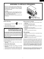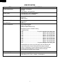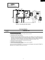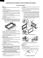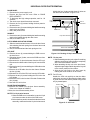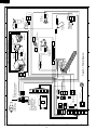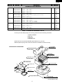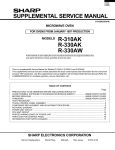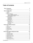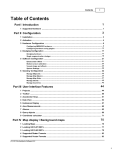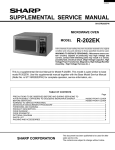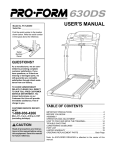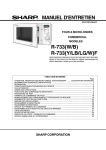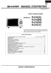
1
R- 630DKA
R- 630DSA
R-630DWA
SERVICE MANUAL
S7118R630DPWA
MICROWAVE OVEN
MODELS
Breakfast Linch
on One Dish
Bar
the Run Dinners Popcorn Baked
Sensor
Potatoes Reheat Custom
More from your Microwave
Help
Sensor Cooking
Super
Compu
Defrost Defrost Beverage Vegetables Main
Frozen
center
Kitchen
Entrees
Foods Timer/Clock
1
2
3
4
5
Power
Level
Minute
PLus
6
7
8
9
0
STOP
Clear
START
Touch on
R-630DKA
R-630DSA
R-630DWA
In the interest of user-safety the oven should be restored to its original
condition and only parts identical to those specified should be used.
WARNING TO SERVICE PERSONNEL: Microwave ovens contain circuitry capable of producing very high voltage and
current, contact with following parts may result in a severe,
possibly fatal, electrical shock. (High Voltage Capacitor, High
Voltage Power Transformer, Magnetron, High Voltage Rectifier Assembly, High Voltage Harness etc..)
This is a supplemental Service Manual for Models R-630DKA, R-630DSA and R-630DWA. These
models are quite similar to base models R-630DK, R-630DS and R-630DW. Use this supplemental manual together with the Base Model Service Manual (Refer No. is S7017R630DPW/) for
complete operation, service information, etc..
TABLE OF CONTENTS
Page
PRECAUTIONS TO BE OBSERVED BEFORE AND DURING SERVICING TO
AVOID POSSIBLE EXPOSURE TO EXCESSIVE MICROWAVE ENERGY ................... INSIDE FRONT COVER
BEFORE SERVICING ...................................................................................................... INSIDE FRONT COVER
WARNING TO SERVICE PERSONNEL ................................................................................................................ 1
MICROWAVE MEASUREMENT PROCEDURE ................................................................................................... 2
FOREWORD AND WARNING ............................................................................................................................... 3
PRODUCT DESCRIPTION .................................................................................................................................... 4
OVEN SCHEMATIC ............................................................................................................................................... 5
TEST PROCEDURE .............................................................................................................................................. 5
COMPONENT REPLACEMENT AND ADJUSTMENT PROCEDURE .................................................................. 6
PICTORIAL DIAGRAM .......................................................................................................................................... 8
PARTS LIST .......................................................................................................................................................... 9
PACKING AND ACCESSORIES ......................................................................................................................... 11
This document has been published to be used for after
sales service only.
The contents are subject to change without notice.
SHARP CORPORATION
15
R- 630DKA
R- 630DSA
R-630DWA
PRECAUTIONS TO BE OBSERVED BEFORE AND
DURING SERVICING TO AVOID POSSIBLE EXPOSURE TO EXCESSIVE MICROWAVE ENERGY
(a) Do not operate or allow the oven to be operated with the door open.
(b) Make the following safety checks on all ovens to be serviced before activating the magnetron or other
microwave source, and make repairs as necessary: (1) interlock operation, (2) proper door closing, (3)
seal and sealing surfaces (arcing, wear, and other damage), (4) damage to or loosening of hinges and
latches, (5) evidence of dropping or abuse.
(c) Before turning on microwave power for any service test or inspection within the microwave generating
compartments, check the magnetron, wave guide or transmission line, and cavity for proper alignment,
integrity, and connections.
(d) Any defective or misadjusted components in the interlock, monitor, door seal, and microwave
generation and transmission systems shall be repaired, replaced, or adjusted by procedures described
in this manual before the oven is released to the owner.
(e) A microwave leakage check to verify compliance with the Federal Performance Standard should be
performed on each oven prior to release to the owner.
BEFORE SERVICING
Before servicing an operative unit, perform a microwave emission check as per the Microwave
Measurement Procedure outlined in this service manual.
If microwave emissions level is in excess of the specified limit, contact SHARP ELECTRONICS
CORPORATION immediately @1-800-237-4277.
If the unit operates with the door open, service person should 1) tell the user not to operate the oven
and 2) contact SHARP ELECTRONICS CORPORATION and Food and Drug Administration's
Center for Devices and Radiological Health immediately.
Service personnel should inform SHARP ELECTRONICS CORPORATION of any certified unit
found with emissions in excess of 4mW/cm2. The owner of the unit should be instructed not to use
the unit until the oven has been brought into compliance.
16
R- 630DKA
R- 630DSA
R-630DWA
WARNING TO SERVICE PERSONNEL
Microwave ovens contain circuitry capable of producing very high voltage and current, contact with
following parts may result in a severe, possibly
fatal, electrical shock.
(Example)
High Voltage Capacitor, High Voltage Power Transformer, Magnetron, High Voltage Rectifier Assembly, High Voltage Harness etc..
Read the Service Manual carefully and follow all
instructions.
Don't Touch !
Danger High Voltage
When the testing is completed,
1. Disconnect the power supply cord, and then remove
outer case.
2. Open the door and block it open.
3. Discharge high voltage capacitor.
4. Reconnect the leads to the primary of the power
transformer.
5. Reinstall the outer case (cabinet).
6. Reconnect the power supply cord after the outer case is
installed.
7. Run the oven and check all functions.
Before Servicing
1. Disconnect the power supply cord
remove outer case.
2. Open the door and block it open.
3. Discharge high voltage capacitor.
, and then
WARNING:RISK OF ELECTRIC SHOCK.
DISCHARGE THE HIGH-VOLTAGE
CAPACITOR BEFORE SERVICING.
After repairing
The high-voltage capacitor remains charged about 60
seconds after the oven has been switched off. Wait for 60
seconds and then short-circuit the connection of the highvoltage capacitor (that is the connecting lead of the highvoltage rectifier) against the chassis with the use of an
insulated screwdriver.
1. Reconnect all leads removed from components during
testing.
2. Reinstall the outer case (cabinet).
3. Reconnect the power supply cord after the outer case is
installed.
4. Run the oven and check all functions.
Whenever troubleshooting is performed the power supply
must be disconnected. It may, in some cases, be necessary
to connect the power supply after the outer case has been
removed, in this event,
1. Disconnect the power supply cord, and then remove
outer case.
2. Open the door and block it open.
3. Discharge high voltage capacitor.
4. Disconnect the leads to the primary of the power
transformer.
5. Ensure that the leads remain isolated from other
components and oven chassis by using insulation tape.
6. After that procedure, reconnect the power supply cord.
Microwave ovens should not be run empty. To test for the
presence of microwave energy within a cavity, place a cup
of cold water on the oven turntable, close the door and set
the power to HIGH and set the microwave timer for two (2)
minutes. When the two minutes has elapsed (timer at zero)
carefully check that the water is now hot. If the water
remains cold, carry out Before Servicing procedure and reexamine the connections to the component being tested.
When all service work is completed and the oven is fully
assembled, the microwave power output should be checked
and a microwave leakage test should be carried out.
1
R- 630DKA
R- 630DSA
R-630DWA
MICROWAVE MEASUREMENT PROCEDURE
A. Requirements:
1) Microwave leakage limit (Power density limit): The power density of microwave radiation emitted by a microwave oven
should not exceed 1mW/cm2 at any point 5cm or more from the external surface of the oven, measured prior to acquisition
by a purchaser, and thereafter (through the useful life of the oven), 5 mW/cm2 at any point 5cm or more from the external
surface of the oven.
2) Safety interlock switches: Primary interlock relay and door sensing switch shall prevent microwave radiation emission
in excess of the requirement as above mentioned, secondary interlock switch shall prevent microwave radiation emission
in excess of 5 mW/cm2 at any point 5cm or more from the external surface of the oven.
B. Preparation for testing:
Before beginning the actual measurement of leakage, proceed as follows:
1) Make sure that the actual instrument is operating normally as specified in its instruction booklet.
Important:
Survey instruments that comply with the requirement for instrumentation as prescribed by the performance standard for
microwave ovens, 21 CFR 1030.10(c)(3)(i), must be used for testing.
2) Place the oven tray in the oven cavity.
3) Place the load of 275±15 ml (9.8 oz) of tap water initially at 20±5˚C (68˚F) in the center of the oven cavity.
The water container shall be a low form of 600 ml (20 oz) beaker with an inside diameter of approx. 8.5 cm (3-1/2 in.)
and made of an electrically nonconductive material such as glass or plastic.
The placing of this standard load in the oven is important not only to protect the oven, but also to insure that any leakage
is measured accurately.
4) Set the cooking control on Full Power Cooking Mode.
5) Close the door and select a cook cycle of several minutes. If the water begins to boil before the survey is completed,
replace it with 275 ml of cool water.
C. Leakage test:
Closed-door leakage test (microwave measurement)
1) Grasp the probe of the survey instrument and hold it perpendicular to the gap between the door and the body of the oven.
2) Move the probe slowly, not faster than 1 in./sec. (2.5 cm/sec.) along the gap, watching for the maximum indication on
the meter.
3) Check for leakage at the door screen, sheet metal seams and other accessible positions where the continuity of the metal
has been breached (eg., around the switches, indicator, and vents).
While testing for leakage around the door pull the door away from the front of the oven as far as is permitted by the closed
latch assembly.
4) Measure carefully at the point of highest leakage and make sure that the highest leakage is no greater than 4mW/cm2.
NOTE: After servicing, record data on service invoice and microwave leakage report.
2
R- 630DKA
R- 630DSA
R-630DWA
SERVICE MANUAL
MICROWAVE OVEN
R-630DKA/ R-630DSA/ R-630DWA
FOREWORD
This Manual has been prepared to provide Sharp Electronics Corp. Service Personnel with Operation and Service
Information for the SHARP MICROWAVE OVEN, R-630DKA, R-630DSA, R-630DWA.
The models R-630DKA, R-630DSA, R-630DWA are quite similar to base models R-630DK, R-630DS and R-630DW
(Refer No. is S7017R630DPW/).
It is recommended that service personnel carefully study the entire text of this manual and the base model's manual so
that they will be qualified to render satisfactory customer service.
Check the interlock switches and the door seal carefully. Special attention should be given to avoid electrical shock and
microwave radiation hazard.
WARNING
Never operate the oven until the following points are ensured.
(A) The door is tightly closed.
(B) The door brackets and hinges are not defective.
(C) The door packing is not damaged.
(D) The door is not deformed or warped.
(E) There is no other visible damage with the oven.
Servicing and repair work must be carried out only by trained service personnel.
DANGER
Certain initial parts are intentionally not grounded and present a risk of electrical shock only during servicing.
Service personnel - Do not contact the following parts while the appliance is energized;
High Voltage Capacitor, Power Transformer, Magnetron, High Voltage Rectifier Assembly, High Voltage
Harness;
If provided, Vent Hood, Fan assembly, Cooling Fan Motor.
All the parts marked “*” on parts list are used at voltages more than 250V.
Removal of the outer wrap gives access to voltage above 250V.
All the parts marked “∆” on parts list may cause undue microwave exposure, by themselves, or when they are
damaged, loosened or removed.
SHARP ELECTRONICS CORPORATION
SHARP PLAZA, MAHWAH,
NEW JERSEY 07430-2135
3
R- 630DKA
R- 630DSA
R-630DWA
SPECIFICATION
ITEM
DESCRIPTION
Power Requirements
120 Volts / 14 Amperes
60 Hertz
Single phase, 3 wire grounded
Power Output
1100 watts (IEC TEST PROCEDURE)
Operating frequency of 2450MHz
Case Dimensions
Width 19-1/2"
Height 14"
Depth 20-5/8"
Cooking Cavity Dimensions
Width 17-3/4"
Height 8-1/4"
Depth 17"
1.4 Cubic Feet
Control Complement
Touch Control System
Clock ( 1:00 - 12:59 )
Timer (0 - 99 min. 99 seconds)
Microwave Power for Variable Cooking
Repetition Rate;
P-HI .................................................. Full power throughout the cooking time
P-90 .................................................................... approx. 90% of Full Power
P-80 .................................................................... approx. 80% of Full Power
P-70 .................................................................... approx. 70% of Full Power
P-60 .................................................................... approx. 60% of Full Power
P-50 .................................................................... approx. 50% of Full Power
P-40 .................................................................... approx. 40% of Full Power
P-30 .................................................................... approx. 30% of Full Power
P-20 .................................................................... approx. 20% of Full Power
P-10 .................................................................... approx. 10% of Full Power
P-0 .................................................... No power throughout the cooking time
Breakfast Bar pad, Lunch on the Run pad, One Dish Dinners pad
Super Defrost pad, Compu Defrost pad, Beverage Center pad
Sensor Cooking pads, Custom Help pad, Kitchen Timer/Clock pad
Number selection pads, Power Level pad, Minute Plus pad
STOP/Clear pad, START/Touch On pad
Oven Cavity Light
Yes
Safety Standard
UL Listed
FCC Authorized
DHHS Rules, CFR, Title 21, Chapter 1, Subchapter J
4
R- 630DKA
R- 630DSA
R-630DWA
SCHEMATIC
NOTE: CONDITION OF OVEN
1. DOOR CLOSED
2. CLOCK APPEARS ON DISPLAY
MONITOR
FUSE 20A
THERMAL
CUT-OUT (OVEN)
THERMAL
CUT-OUT (MG.)
N.O.
POWER
TRANSFORMER
N.O.
F2
F1
PRIMARY
INTERLOCK
RELAY
AH SENSOR
(RY-2)
(RY-1)
A1
CONTROL UNIT
COM.
COM.
B2
GRN
120V AC
60 Hz
B1
DOOR
SENSING
SWITCH
OL
OVEN
LAMP
TTM
FM
CAPACITOR 0.94µF
AC 2200V
F3
A2
MONITOR
SWITCH
RECTIFIER
MAGNETRON
SECONDARY
INTERLOCK
SWITCH
TURNTABLE
MOTOR
FAN
MOTOR
Figure O-1. Oven Schematic-Off Condition
TEST PROCEDURES
PROCEDURE
LETTER
B
COMPONENT TEST
POWER TRANSFORMER TEST
1.
2.
3.
4.
5.
6.
7.
8.
Disconnect the power supply cord, and then remove outer case.
Open the door and block it open.
Discharge the high voltage capacitor.
Disconnect the primary input terminals and measure the resistance of the transformer with an
ohmmeter. Check for continuity of the coils with an ohmmeter. On the R x 1 scale, the resistance of
the primary coil should be less than 1 ohm and the resistance of the high voltage coil should be
approximately 77 ohms; the resistance of the filament coil should be less than 1 ohm.
Reconnect all leads removed from components during testing.
Reinstall the outer case (cabinet).
Reconnect the power supply cord after the outer case is installed.
Run the oven and check all functions.
(HIGH VOLTAGES ARE PRESENT AT THE HIGH VOLTAGE TERMINAL, SO DO NOT ATTEMPT TO
MEASURE THE FILAMENT AND HIGH VOLTAGE.)
5
R- 630DKA
R- 630DSA
R-630DWA
COMPONENT REPLACEMENT AND ADJUSTMENT PROCEDURE
DOOR REPLACEMENT
REMOVAL
1. Disconnect the power supply cord and then remove the
outer case.
2. Open the door slightly.
3. To discharge high voltage capacitor, wait for 60 seconds.
4. Disconnect the 12-pin wire harness from the power unit
on the base plate.
5. Insert a putty knife (thickness of about 0.5mm) into the
gap between the choke cover and door frame as shown
in Figure C-6 to free engaging parts.
6. Pry the choke cover by inserting a putty knife as shown
Figure C-6.
7. Release choke cover from door panel.
8. Now choke cover is free.
NOTE: When carrying out any repair to the door, do not
bend or warp the slit choke (tabs on the door
panel assembly) to prevent microwave leakage.
3. Door is positioned with its face pressed toward cavity
face plate.
4. Check for microwave leakage around door with an
approved microwave survey meter. (Refer to Microwave
Measurement Procedure.)
Note: The door on a microwave oven is designed to act as
an electronic seal preventing the leakage of
microwave energy from oven cavity during cook cycle.
This function does not require that door be air-tight,
moisture (condensation)-tight or light-tight. Therefore,
occasional appearance of moisture, light or sensing
of gentle warm air movement around oven door is not
abnormal and do not of themselves indicate a leakage
of microwave energy from oven cavity.
Upper
Pin oven
hinge
Upper oven hinge
Choke cover
Slit choke of
door panel
Lower oven
hinge
Door frame
Putty knife
Figure C-6. Door Disassembly
9. Release two (2) pins of door panel from two (2) holes of
upper and lower oven hinges by lifting up.
10.With pulling out the 12-pin wire harness from the hole of
the oven cavity front plate and the front leg, remove the
door from the oven cavity.
11.Now, the door is free from the oven cavity.
REINSTALLATION
1. Insert the 12-pin wire harness to the holes of the front leg
and the oven cavity front plate.
2. Catch two (2) pins of door panel on two (2) hole of upper
and lower oven hinges.
3. Re-install choke cover to door panel by pushing.
4. Connect the 12-pin wire harness to the power unit on the
base plate.
5. Now the door is installed.
Note: After any service to the door;
(A) Make sure that door sensing switch and secondary
interlock switch are operating properly. (Refer to
chapter “Test Procedures”.).
(B) An approved microwave survey meter should be
used to assure compliance with proper microwave
radiation emission limitation standards.
After any service, make sure of the following :
1. Door latch heads smoothly catch latch hook through
latch holes and that latch head goes through center of
latch hole.
2. Deviation of door alignment from horizontal line of cavity
face plate is to be less than 1.0mm.
Pin
Choke cover
Lower
oven
hinge
Figure C-7. Door Replacement
12-pin wire
harness
Power unit
Door
12-pin wire harness
Tab
Front leg
e
Hol
Door Screen
Hole
Front leg
Oven cavity front plate
Base plate
Figure C-8. Routing of 12-pin wire harness
SEALER FILM
Installation
1. Put the adhesive tape on the backing film of the sealer
film as shown in Fig. C-9.
2. Tear the backing film by pulling the adhesive tape.
3. Put the pasted side of the sealer film on the door panel.
Sealer film
Backing film
Adhesive tape
Figure C-9. Sealer film
6
R- 630DKA
R- 630DSA
R-630DWA
INDIVIDUAL DOOR PARTS REMOVAL
DOOR PANEL
1. Disconnect the power supply cord.
2. Remove the door from the oven. Refer to "DOOR
REPLACEMENT".
3. To discharge the high voltage capacitor, wait for 60
seconds.
4. The choke cover should have been removed.
5. Remove the five (5) screws holding the door panel to
the door frame.
6. Remove the two (2) screws holding the handle mounting
angle to the door panel.
7. Now, door panel is free.
held by the four (4) tabs and the three (3) holes on
the door frame as shown in Figure C-10.
Tab
Hole of
PWB cover
Hole on
door frame
Tabs
PWB Cover
HANDLE
8. Remove the two (2) screws holding the handle mounting
angle to the handle through the door frame.
9. Now, the handle is free.
12-pin wire harness
LATCH HEAD AND LATCH SPRING
8. Slide the latch head and remove it from the door frame
with releasing the latch spring from the door frame and
the latch head.
9. Now, the latch head and the latch spring are free.
Tab
Hole on door frame
Hole on door frame
CPU UNIT
8. Remove the two (2) screws holding the PWB cover to
the door frame.
9. Releasing the two (2) tabs, remove the PWB cover from
the door frame.
10.Disconnect the 12-pin wire harness from the CPU unit.
11.Disconnect the ribbon cable of the key unit from the CPU
unit.
12.Remove the two (2) screws holding the LCD holder to the
door frame.
13.Remove the LCD holder from the door frame. Release
the four (4) tabs.
14.Release the LCD of the CPU unit from the LCD holder.
15.Remove the two (2) screws holding the CPU unit to the
LCD holder.
16.Remove the CPU unit from the LCD holder. Release the
four (4) tabs.
17.Now the CPU unit is free.
Figure C-10. Routing of 12-pin wire harness
NOTE: For key unit
1. Before attaching a new key unit, wipe off remaining
adhesive on the door frame surfaces completely
with a soft cloth soaked in alcohol.
2. When attaching the key unit to the door frame,
adjust the upper edge and left edge of the key unit
to the correct position of door frame.
3. Stick the key unit firmly to the door frame by
rubbing with a soft cloth so not to scratch.
NOTE: For CPU unit
Handle the CPU unit carefully so that the ribbon
cable does not come off. Because the ribbon cable
is glued onto the LCD and the printed wiring board
only by heated paste.
Liquid Crystal
Display (LCD)
NOTE: For 12-pin wire harness
1. When the PWB cover is reinstalled, route the 12-pin
wire harness under the hole of the PWB cover.
2. Before the door panel is reinstalled to the door frame
assembly, make sure that the 12-pin wire harness is
Printed wiring board
of CPU unit
Ribbon cable
DOOR FRAME ASSEMBLY
18.Remove the handle from the door frame assembly.
Refer to the chapter of HANDLE.
19.Now, the door frame assembly is free.
Figure C-11. CPU unit
7
N
G
1
2
3
4
8
5
H
6
BLU/
12
GRN
1
3
CN-F
12
2
CN-F
1 BLK
2 RED
3 WHT
CN-B
3 GRY
2
1 GRN
AH SENSOR
POWER UNIT
CN-C
1
CN-B
RED
YLW
YLW
2
Figure S-1. Pictorial Diagram
FAN MOTOR
BLK
BLK
GRY
WHT
BLK
N.C.
COM.
WHT
GRY
WHT
WHT
WHT
COM.
SECONDARY NO
INTERLOCK
SWITCH
MONITOR
SWITCH
RED
BLK
YLW
5
PNK 11
GRY 8
WHT 9
BLK 10
PPL 7
BLU 6
GRN 5
ORG 3
YLW 4
RED 2
RY2
PRIMARY
INTERLOCK
RELAY
1
RY1
2
CN-A
1 WHT
BLK
MONITOR FUSE
& HOLDER
BLK
WHT
GRN
GRY
THERMAL
CUT-OUT (MG)
N.O.
4
BRN 1
CN-C
RED
BLK
1
2 RED
1 BRN
3 ORG
4 YLW
TURNTABLE
MOTOR
B
CN-A
CPU UNIT
(on the door)
CN-C
1
BLK 2 BLK
COM.
DOOR
SENSING
SWITCH
OVEN LAMP
3
RED
RED
12
12
WHT 1 WHT
THERMAL
CUT-OUT (OVEN)
BLK
MAGNETRON
YLW
WHT
A
6 BLU
5 GRN
7 PPL
8 GRY
9 WHT
BLK
H.V.
RECTIFIER
POWER
TRANSFORMER
HIGH VOLTAGE
CAPACITOR
2
CN-G
1
CN-C
10 BLK
RED
GRY
GRY
HIGH VOLTAGE
WIRE B
1
11 PNK
12 BLU/
GRN
BLK
WHT
WHT
E
NOTE:
The grounding conductor of
the power supply cord has
been grounded by power
supply cord fixing screw.
The screw must allways be
kept tight.
F
NOTE:
The neutral (WHT) wire must be
connected to the neutral (WHT)
wire of the power supply cord.
D
H
POWER SUPPLY
CORD 120V 60Hz
C
HIGH VOLTAGE COMPONENTS
R- 630DKA
R- 630DSA
R-630DWA
6
A
B
C
D
E
F
G
H
R- 630DKA
R- 630DSA
R-630DWA
PARTS LIST
Note: The parts marked “∆” may cause undue microwave exposure.
The parts marked “*” are used in voltage more than 250V.
REF. NO.
PART NO.
DESCRIPTION
Q'TY
CODE
1
1
1
2
2
1
1
1
1
1
1
1
1
1
1
1
1
1
1
1
1
1
1
1
1
AQ
AQ
AH
AH
AF
AS
AK
AK
AT
AP
AV
AS
AV
AX
AW
BL
BK
AU
AL
AW
AQ
AS
AK
AK
BG
1
1
1
1
1
1
1
1
1
1
AY
AC
AC
BD
BD
BD
AL
AL
AL
AC
1
1
1
1
1
1
1
1
2
1
1
1
1
1
1
1
1
1
1
1
1
1
1
1
1
BB
AC
AC
AE
AD
AF
AA
AA
AA
AG
AK
AA
AA
AA
AA
AC
AC
AA
AA
AK
AM
AG
AP
AE
AA
1
AH
ELECTRIC PARTS
*
*
*
*
*
*
*
∆*
1- 1
1- 1
1- 2
1- 3
1- 3
1- 4
1- 5
1- 5
1- 6
1- 6
1- 7
1- 7
1- 7
1- 8
1- 8
1- 9
1- 9
1-10
1-11
1-12
1-12
1-12
1-13
1-13
1-14
FACCDA085WREZ
FACCDA083WRE0
QFSHDA009WRE0
QSW-MA137WRE0
QSW-MA085WRE0
FFS-BA023WRK0
RTHM-A116WRE0
RTHM-A078WRE0
FH-DZA101WRKZ
FH-DZA097WRKZ
RC-QZA286WRZZ
RC-QZA268WRZZ
RC-QZA211WRE0
RMOTEA401WRZZ
RMOTEA395WRZZ
RTRN-A636WRZZ
RTRN-A609WRZZ
FDTCTA209WRKZ
RLMPTA082WRZZ
RMOTDA186WRE0
RMOTDA229WRE0
RMOTDA211WRE0
RTHM-A123WRZZ
RTHM-A096WRE0
RV-MZA310WRZZ
Power supply cord
Power supply cord (Interchangeable)
Fuse holder
2nd interlock switch / door sensing switch
2nd interlock switch / door sensing switch(Interchangeable)
Monitor fuse 20A and monitor switch (AM51620C53Y1) assembly
Thermal cut-out 125 deg. C (MG)
Thermal cut-out 125 deg. C (MG) (Interchangeable)
High voltage rectifier assembly
High voltage rectifier assembly (Interchangeable)
High voltage capacitor
High voltage capacitor (Interchangeable)
High voltage capacitor (Interchangeable)
Fan motor
Fan motor (Interchangeable)
Power transformer
Power transformer (Interchangeable)
AH sensor
Oven lamp
Turntable motor
Turntable motor (Interchangeable)
Turntable motor (Interchangeable)
Thermal cut-out 125 deg. C (OVEN)
Thermal cut-out 125 deg. C (OVEN) (Interchangeable)
Magnetron
2222222222-
FDAI-A215WRYZ
GLEGPA074WRE0
GLEGPA081WRFZ
GCABUA773WRPZ
GCABUA775WRPZ
GCABUA777WRPZ
GLEGPA080WRFZ
GLEGPA082WRFZ
GLEGPA080WRFZ
PPACGA180WREZ
Base plate
Foot
Leg
Outer case
Outer case
Outer case
Front leg
Front leg
Front leg
Cushion
DPWBFC096WRUZ
QCNCMA446DRE0
QCNCMA431DRE0
QCNCMA463DRZZ
QCNCMA237DRE0
VCEAB31VW108M
RC-KZA087DRE0
VCEAB31VW106M
RC-KZA087DRE0
RSRCDA013DRE0
VHIBA4558//-6
VS2SB1238//-3
VRD-B12EF242J
VRD-B12HF681J
VRS-B13AA331J
RR-DZA285DRZZ
RR-DZA286DRZZ
VRN-B12EK182F
VRN-B12EK364F
RRLY-A076DRE0
RRLY-A113DRE0
RALM-A014DRE0
RTRNPA111DRE0
RH-VZA032DRE0
VHEHZ161///-1
Power unit
2-pin connector (CN-A)
2-pin connector (CN-B)
12-pin connector (CN-C)
3-pin connector (CN-F)
Capacitor
1000 uF
35V
Capacitor
0.1 uF
50V
Capacitor
10 uF
35V
Capacitor
0.1 uF
50V
Diode (S1NB10)
IC (BA4558)
Transistor (2SB1238)
Resistor
2.4k ohm
1/4W
Resistor
680 ohm
1/2W
Resistor
330 ohm
1W
Resistor
3.32k ohm ±0.5% 1/4W
Resistor
3.57k ohm ±0.5% 1/4W
Resistor
1.8k ohm ±1.0% 1/4W
Resistor
360k ohm ±1.0% 1/4W
Relay (OMIF-S-124LM)
Relay (DU24D1-P(M)-R)
Buzzer (PKM22EPT)
Transformer
Varistor (10G471K)
Zener diode (HZ16-1)
CABINET PARTS
1
2
3
4
4
4
5
5
5
6
cabinet [R-630DKA]
cabinet [R-630DWA]
cabinet [R-630DSA]
[R-630DKA]
[R-630DWA]
[R-630DSA]
POWER UNIT PARTS
3- 1
3- 1A
3- 1B
3- 1C
3- 1D
C1
C2
C3
C50-51
D1
IC2
Q1
R1
R2
R50
R51
R52
R53
R54
RY1
RY2
SP1
T1
VRS1
ZD1
OVEN PARTS
∆ 4- 1
PHOK-A118WRFZ
Latch hook
9
R- 630DKA
R- 630DSA
R-630DWA
∆
REF. NO.
4- 2
4- 3
4- 4
4- 5
4- 6
4- 7
4- 8
4- 9
4-10
4-11
4-12
4-13
4-14
4-15
4-16
4-17
4-18
4-19
4-20
4-21
4-22
4-23
4-24
4-25
4-26
4-27
4-28
4-29
4-30
PART NO.
LBNDKA099WRW0
LFLG-A028WREZ
FANGKA211WRWZ
LANGRA055WRWZ
LANGRA056WRWZ
NFANJA046WREZ
LANG-A069WRPZ
LANG-A080WRWZ
PPACGA084WRF0
LANG-A081WRWZ
*************
GCOVHA419WRFZ
LANGQA536WRWZ
LANG-A077WRPZ
PCOVPA361WREZ
PCUSGA057WRP0
PCUSUA557WRPZ
PCUSUA556WRPZ
PCUSUA126WRE0
PPACGA177WREZ
PCUSGA505WRP0
PCUSUA376WRP0
PCUSUA409WRP0
PCUSUA558WRPZ
PDUC-A761WRTZ
LANGFA200WRPZ
PCUSUA375WRP0
PCUSUA562WRPZ
PCUSUA568WRPZ
DESCRIPTION
Capacitor holder
Bearing
Fan case assembly
Fan motor mounting angle
Bearing holder
Closs flow fan
Magnetron air guide A
Magnetron air guide B
TTM packing
Separate angle B
Oven cavity (Not a replaceable part)
Choke cover
Lamp angle
Magnetron thermal cut-out angle
Waveguide cover
Cushion
Cushion
Cushion
Cushion
Cushion
Cushion
Cushion
Cushion
Cushion
Exhaust duct
Support angle
Cushion
Cushion
Cushion
5- 1
5- 2
5-3-1
5-3-1
5-3-1
5-3-2
5-3-2
5-3-2
5- 3
5- 3
5- 3
5- 4
5- 4
5- 4
5- 5
5- 6
5- 7
5- 8
5- 9
5-10
5-11
5-12
5-13
5-14
5-15
5-16
5-17
5-18
FDORFA343WRTZ
PSHEPA735WREZ
FUNTKB084WREZ
FUNTKB085WREZ
FUNTKB084WREZ
HPNL-A768WRRZ
HPNL-A770WRRZ
HPNL-A768WRRZ
FWAKPA346WRKZ
FWAKPA348WRKZ
FWAKPA344WRKZ
JHNDPA203WRTZ
JHNDPA203WRTZ
JHNDPA205WRTZ
LANGKA975WRPZ
LSTPPA193WRFZ
MSPRTA187WRE0
LHLD-A226WRFZ
PSHEPA672WRE0
FW-VZA268DREZ
DPWBFC097WRKZ
PCOVPA367WRWZ
PCUSUA569WRPZ
XCPSD40P06000
XEPSD40P16000
XEPSD30P08XS0
XEPSD40P08000
LX-EZA059WREZ
Door panel
Sealer film
Key unit [R-630DKA]
Key unit [R-630DWA]
Key unit [R-630DSA]
Door screen [R-630DKA]
Door screen [R-630DWA]
Door screen [R-630DSA]
Door frame assembly [R-630DKA]
Door frame assembly [R-630DWA]
Door frame assembly [R-630DSA]
Handle [R-630DKA]
Handle [R-630DWA]
Handle [R-630DSA]
Handle mounting angle
Latch head
Latch spring
LCD holder
LED sheet
12-pin wire harness
CPU unit
PWB cover
Cushion
Screw : 4mm x 6mm
Screw : 4mm x 16mm
Screw : 3mm x 8mm
Screw : 4mm x 8mm
Special screw
6- 1
6- 2
6- 3
6- 4
6- 5
6- 6
6- 7
6- 8
6- 9
6-10
6-11
6-12
6-13
FROLPA097WRKZ
NTNT-A099WRE0
FW-VZB830WREZ
QW-QZA242WRZZ
TCADCA724WRRZ
TCAUAA156WRR0
TCAUAA201WRR0
TCAUAA254WRR0
TCAUAA255WRR0
TINSEA912WRRZ
FW-VZB801WREZ
FW-VZB802WREZ
TLABMA646WRRZ
Turntable support
Turntable tray
Main wire harness
High voltage wire B
Recipe sheet
User caution label
DHHS caution label
Monitor caution label
Screw caution
Instruction book
Switch harness
T.T. motor harness
Menu label
Q'TY
1
1
1
1
1
1
1
1
1
1
1
1
1
1
1
2
1
1
1
1
1
1
1
1
1
1
1
1
1
CODE
AD
AL
AP
AE
AF
AG
AL
AC
AE
AD
-AK
AS
AC
AD
AA
AC
AC
AC
AC
AB
AF
AD
AC
AL
AD
AH
AB
AE
1
1
1
1
1
1
1
1
1
1
1
1
1
1
1
1
1
1
1
1
1
1
1
2
2
4
5
2
AS
AG
AT
AT
AT
AZ
AZ
AZ
BF
BF
BF
AP
AP
AQ
AP
AE
AC
AD
AK
AQ
BH
AD
AE
AA
AA
AA
AA
AD
1
1
1
1
1
1
1
1
1
1
1
1
1
AN
AX
AX
AF
AD
AF
AE
AC
AC
AE
AF
AF
AC
DOOR PARTS
∆
∆
∆
∆
∆
∆
∆
∆
MISCELLANEOUS
*
10
R- 630DKA
R- 630DSA
R-630DWA
REF. NO.
PART NO.
DESCRIPTION
Q'TY
CODE
4
2
12
2
2
2
5
2
2
1
13
1
3
2
2
2
2
1
4
2
1
AA
AA
AA
AA
AC
AB
AA
AC
AA
AA
AA
AA
AA
AA
AA
AA
AA
AA
AA
AB
AA
SCREWS,NUTS AND WASHERS
7- 1
7- 2
7- 3
7- 4
7- 5
7- 6
7- 7
7- 8
7- 9
7-10
7-11
7-12
7-13
7-14
7-14
7-14
7-15
7-16
7-17
7-18
7-19
XHPSD40P08K00
XBPSD40P08K00
XOTSD40P08000
XHTSD40P06000
LX-CZA073WRE0
XHPSD30P08XS0
XHTSD40P08RV0
LX-CZA070WRE0
LX-CZ0052WRE0
XHPSD30P06000
XHTSD40P08000
XHTSD40P12RV0
XOTSD40P12RV0
XOTSF40P08000
XOTSE40P08000
XOTSE40P08000
XOTSD40P12000
XOTSD40P10000
LX-EZA060WREZ
XHBWW30P08000
XCPSD40P08000
Screw :
Screw :
Screw :
Screw :
Special
Screw :
Screw :
Special
Special
Screw :
Screw :
Screw :
Screw :
Screw :
Screw :
Screw :
Screw :
Screw :
Special
Screw :
Screw :
4mm x
4mm x
4mm x
4mm x
screw
3mm x
4mm x
screw
screw
3mm x
4mm x
4mm x
4mm x
4mm x
4mm x
4mm x
4mm x
4mm x
screw
3mm x
4mm x
8mm
8mm
8mm
6mm
8mm
8mm
(Torx tamper proof screw)
6mm
8mm
12mm
12mm
8mm [R-630DKA]
8mm [R-630DWA]
8mm [R-630DSA]
12mm
10mm
8mm
8mm
HOW TO ORDER REPLACEMENT PARTS
To have your order filled promptly and correctly, please furnish the following information.
1. MODEL NUMBER
2. REF. NO.
3. PART NO.
4. DESCRIPTION
Order Parts from the authorized SHARP parts Distributor for your area.
Defective parts requiring return should be returned as indicated in the Service Policy.
PACKING AND ACCESSORIES
TOP PAD ASSEMBLY
DOOR PROTECTION SHEET
FPADBA426WRKZ
SPADPA178WRE0
PLASTIC BAG
SSAKHA032WRE0
CABINET COVER (for R-630DKA/DSA)
FORM SHEET (for R-630DKA/DSA)
SPAKHA016WREZ
SPAKHA015WREZ
6-10 INSTRUCTION BOOK
& PRINTING MATTER
BOTTOM PAD ASSEMBLY
6- 2
TURNTABLE TRAY
FPADBA427WRKZ
6- 1 TURNTABLE SUPPORT
TRAY PACK
INTO THE
OVEN CAVITY
SPADFA481WREZ
Not replaceable items.
11
PACKING CASE
SPAKCD439WREZ [R-630DKA]
SPAKCD438WREZ [R-630DWA]
SPAKCD437WREZ [R-630DSA]
R- 630DKA
R- 630DSA
R-630DWA
2
1
4
3
6
5
OVEN AND CABINET PARTS
7-13
7-18
A
2-4
4-23
A
1-10
7-5
7-14
4-26
4-17
7-8
B
B
1-13
6-8
4-22
7-12
6-9
4-12
4-30
1-1
4-28
C
7-14
7-3
4-27
4-17
C
4-18
6-7
7-5
7-11
6-6
7-1
1-11
7-3
4-11
4-19
7-3
D
7-4
7-3
D
4-14
7-11
7-11
7-3
4-15
A
4-16
4-10
4-20
7-10
7-11
4-9
7-17
1-12
6-13
7-9
1-5
7-4
7-11
E
1-3
1-14
1-8
7-3
7-11
E
4-4
7-11
7-1
1-4
4-1
7-11
7-15
4-7
7-2
1-3
4-25
2-5
F
4-21
2-6
4-6
7-7
F
7-3
1-4
1-6
7-7
7-15
4-8
4-3
4-5
4-2
7-6
7-19
7-1
6-2
1-2
1-7
1-9
2-3
4-24
G
G
3-1
7-16
6-1
2-1
A
H
H
2-2
4-29
1
2
4
3
12
5
6
R- 630DKA
R- 630DSA
R-630DWA
2
1
4
3
6
5
A
A
DOOR PARTS
5-16
5-16
5-11
B
5-8
5-9
B
5-12
5-18
5-17
5-13
4-13
5-16
5-2
5-18
C
5-17
5-17
5-1
C
5-10
5-14
5-3
5-5
5-17
5-3-1
D
D
5-14
5-15
5-3-2
5-6
5-7
E
E
MISCELLANEOUS
5-4
6-3
F
F
(CAPACITOR)
Actual wire harness may be different from illustration.
6-11
6-4
G
G
6-12
H
H
1
2
4
3
13
5
6
R- 630DKA
R- 630DSA
R-630DWA
COPYRIGHT © 2001 BY SHARP CORPORATION
ALL RIGHTS RESERVED.
No part of this publication may be reproduced,
stored in retrieval systems, or transmitted in any
form or by any means, electronic, mechanical, photocopying, recording, or otherwise, without prior
written permission of the publisher.
2001 SHARP CORP. (7S1.700E) Printed in U.S.A
14