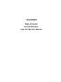
1
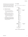
1433 SERIES High-Accuracy Decade Resistor User and Service Manual 1433 Series Contents Chapter 1 Introduction...............................................................................1 1.1 Product Overview.................................................................................................. 1 Chapter 2 Specifications............................................................................2 Decade Specifications..................................................................................................... 2 Chapter 3 Operation...................................................................................5 3.1 Initial Inspection and Setup................................................................................... 5 3.2 Connection............................................................................................................. 5 3.2.1 General Considerations................................................................................ 5 3.2.2 Electrical Considerations............................................................................. 5 3.2.3 Four-Wire Kelvin-Lead Connections.......................................................... 6 3.2.4 Thermal emf Considerations........................................................................ 6 3.3 Dial Setting............................................................................................................ 6 Chapter 4 Maintanence...............................................................................7 4.1 Preventative Maintenance...................................................................................... 7 4.2 Calibration Interval................................................................................................ 7 4.3 General Considerations.......................................................................................... 7 4.4 Calibration Procedure............................................................................................ 8 4.5 Schematic............................................................................................................... 8 4.6 Replaceable Parts List............................................................................................ 9 1433 Series Tables and Figures Figure 1-1: 1433 Series High Accuracy Decade Resistor........................................ 1 Figure 2-1: Sample operating guide affixed to unit.................................................. 4 Figure 3-1: Optimal 4-Wire Kelvin Lead Connection................................................ 6 Figure 4-1: 1433 Series Schematic Diagram........................................................... 8 Table 4-1: Replacement List..................................................................................... 9 Figure 4-2: 1433 Replaceable Parts........................................................................ 9 1433 Series Chapter 1 INTRODUCTION 1.1 Product Overview The 1433 Decade Resistors are a family of instruments providing a very broad choice of high-performance resistance sources. Any number of decades from one to eleven is available. The 1433 is a precision resistance source with excellent characteristics of stability, temperature coefficient, power coefficient, and frequency response. There are over 30 models available covering a wide resistance range from 1 mΩ to over 111 MΩ. The 1433 Series employs stable, very-low-resistance switches with silver-alloy contacts. A special design keeps zero-resistance to less than 1 mΩ per decade. Self-cleaning keeps the silver contacts from becoming tarnished when unused, or when only low currents are passed through them. This is most often the case when only minute test currents are drawn by digital multimeters or other test instruments. Contact resistance is stable and remains low and repeatable. High-quality gold-plated, tellurium-copper binding posts serve to minimize the thermal emf effects which can introduce errors into dc resistance measurements. All other conductors within the instrument, as well as the solder employed, contain no metals or junctions that contribute to thermal emf problems. With a minimum resistance as low as 1 mΩ and a maximum available resistance of over 111 MΩ, the 1433 series may be used for exacting precision measurement applications requiring high accuracy, good stability, and low zero-resistance. They can be used as components of dc and ac bridges, for calibration, as transfer standards, and as RTD simulators. The 1433 Series may be rack-mounted to serve as components in measurement and control systems. The dials, marked “0” to “10”, offer smooth rotation from position to position with no stops. Each dial has an overlap “10” position for maximum convenience and flexibility in setting and adjusting resistance values. The resistance per step and maximum current of each dial are clearly shown on the front panel. Electrical shielding is provided by an attractive aluminum cabinet and front panel. The resistance elements have no electrical connection to the cabinet and panel; a separate shield terminal is provided. Introduction 1 1433 Series Chapter 2 SPECIFICATIONS For the convenience of the user, the pertinent specifications are given in an OPERATING GUIDE affixed to the case of the instrument. Decade Specifications Resistance per step 1 mΩ Total Max voltage Max power Stability decade Max current (per step) (per step) (±ppm/yr) resistance 5 mV 0.04 W Long-term stability (±ppm/3 yrs) Temperature coefficient (±ppm/°C) 75 50 10 mΩ 8.0 A 50 10 mΩ 100 mΩ 4.0 A 40 mV 0.16 W 50 75 20 100 mΩ 1Ω 1.6 A 0.16 V 0.25 W 50 75 20 1Ω 10 Ω 0.8 A 0.8 V 0.6 W 20 25 20 10 Ω 100 Ω 0.25 A 2.5 V 0.6 W 20 25 15 100 Ω 1 kΩ 80 mA 8V 0.6 W 20 25 5 1 kΩ 10 kΩ 23 mA 23 V 0.5 W 20 25 5 10 kΩ 100 kΩ 7 mA 70 V 0.5 W 20 25 5 100 kΩ 1 MΩ 2.3 mA* 230 V* 0.5 W* 20 25 5 1 MΩ 10 MΩ 0.7 mA* 700 V* 0.5 W* 20 25 5 10 MΩ 100 MΩ 0.1 mA* 1000 V* 0.1 W* 50 100 10 Resistor type Resistance wire Wirewound, noninductive Metal oxide film *Subject to maximum of 2000 V to case Accuracy: ≤1 MΩ decades: ±(0.01% + 2 mΩ) 10 MΩ decades: ±0.03% after subtraction of zero resistance, at 23°C; traceable to SI Zero resistance: ≤1 MΩ decades: <1 mΩ per decade at dc 10 MΩ decade: ≈3 mΩ at dc Max voltage to case: 2000 V peak Terminals: Gold-plated, 5-way, tellurium-copper binding posts with low thermal emf and low resistance. Rear outputs are available as an option. Typical Value of Zero Impedance: Zero Resistance (Ro): <0.001 Ω/decade at dc 0.04 Ω/decade at 1 MHz Proportional to square root of frequency above 100 kHz 2 Switch capacitance: < 1 pF between contacts Zero Inductance (Lo): 0. 1 µH/decade + 0.2 µH. Switches: Continuous rotation 11 positions marked “0”-”10” Multiple solid silver-alloy contacts Mechanical: Model 3 decade Dimensions 31 cm W x 8.9 cm H x 10.2 cm D (12.2" x 3.5" x 4") Weight 1.7 kg 3.8 lb 4-5 decade 37.6 cm W x 8.9 cm H x 10.2 cm D (14.8" x 3.5" x 4") 2.0 kg 4.3 lb 6-7 decades 43.9 cm W x 8.9 cm H x 10.2 cm D (17.3" x 3.5" x 4") 2.4 kg 5.3 lb 8-9 decades 48.3 cm W x 17.8 cm H x 17.8 cm D (19" x 7" x 7") 10-11 decades 3.5 kg 7.7 lb 3.7 kg 8.1 lb Specifications 1433 Series Environmental conditions: Operating: 10°C to 40°C; <50% RH Storage: -40°C to 70°C Supplied with unit: Instruction manual Calibration Certificate Model Total resistance Number of Resolution decades Historic GR model numbers Model Total resistance Number of Resolution decades Historic GR model numbers 1433-01 1.11 Ω 3 0.001 Ω 1433-00 111.1 Ω 4 0.01 Ω 1433-U 1433-29 111.1111 k Ω 7 0.01 Ω 1433-F 1433-02 1.111 kΩ 4 0.1 Ω 1433-K 1433-31 1.111 111 MΩ 7 0.1 Ω 1433-G 1433-04 11.11 k Ω 4 1Ω 1433-J 1433-33 11.111 11 MΩ 7 1Ω 1433-H 1433-06 111.1 k Ω 4 10 Ω 1433-L 1433-34 111.1111 MΩ 7 10 Ω 1433-08 1.111 MΩ 4 100 Ω 1433-Q 1433-35 111.111 11 kΩ 8 0.001 Ω 1433-09 11.11 MΩ 4 1 kΩ 1433-36 1.111 111 1 MΩ 8 0.01 Ω 1433-09A 111.1 MΩ 4 10 kΩ 1433-37 11.111 111 MΩ 8 0.1 Ω 1433-10 1.1111 kΩ 5 0.01 Ω 1433-T 1433-38 111.111 11 MΩ 8 1Ω 1433-12 11.111 kΩ 5 0.1 Ω 1433-N 1433-39 1.111 111 11 MΩ 9 0.001 Ω 1433-14 111.11 kΩ 5 1Ω 1433-M 1433-39A 11.111 111 1 MΩ 9 0.01 Ω 1433-16 1.1111 M Ω 5 10 Ω 1433-P 1433-39B 111.111 111 MΩ 9 0.1 Ω 1433-18 11.111 MΩ 5 100 Ω 1433-Y 1433-40A 11.111 111 11 MΩ 10 0.001 Ω 1433-18A 111.11 MΩ 5 1 kΩ 1433-40 111.111 111 1 MΩ 10 0.01 Ω 1433-19 1.111 11 kΩ 6 0.001 Ω 1433-41 111.111 111 11 MΩ 11 0.001 Ω 1433-20 11.1111 kΩ 6 0.01 Ω 1433-W 1433-22 111.111 kΩ 6 0.1 Ω 1433-X 1433-24 1.111 11 MΩ 6 1Ω 1433-B 1433-26 11.1111 MΩ 6 10 Ω 1433-Z 1433-27 111.111 MΩ 6 100 Ω Specifications 1433-28 11.111 11 kΩ 7 0.001 Ω 3 1433 Series 4 1433 SERIES Resistance per step Total deacde resistance Max current Max Power voltage per/step 10 m 8.0 A 5 mV 1 m 100 m 4.0 A 40 mV 10 m 1 1.6 A 0.16 V 100 m 10 0.8 A 0.8 V 1 100 0.25 A 2.5 V 10 1 k 80 mA 8V 100 10 k 23 mA 23 V 1 k 100 k 7 mA 70 V 10 k 1 M 2.3 mA* 230 V* 100 k 10 M 0.7 mA* 700 V* 1 M 100 M 0.1 mA* 1000 V* 10 M *Subject to maximum of 2000 V to case 0.04 W 0.16 W 0.25 W 0.6 W 0.6 W 0.6 W 0.5 W 0.5 W 0.5 W* 0.5 W* 0.1 W* PRECISION DECADE RESISTORS Stability Long-term stability ±50 ppm/yr ±50 ppm/yr ±50 ppm/yr ±20 ppm/yr ±20 ppm/yr ±20 ppm/yr ±20 ppm/yr ±20 ppm/yr ±20 ppm/yr ±20 ppm/yr ±50 ppm/yr ±75 ppm/3 yrs ±75 ppm/3 yrs ±75 ppm/3 yrs ±25 ppm/3 yrs ±25 ppm/3 yrs ±25 ppm/3 yrs ±25 ppm/3 yrs ±25 ppm/3 yrs ±25 ppm/3 yrs ±25 ppm/3 yrs ±100 ppm/3 yrs Temp. coeffieient Resistor type ± 50 ppm/°C Resistance ± 20 ppm/°C Wire ± 20 ppm/°C ± 20 ppm/°C ± 15 ppm/°C ± 5 ppm/°C Wirewound, ± 5 ppm/°C non-inductive ± 5 ppm/°C ± 5 ppm/°C ± 5 ppm/°C ± 10 ppm/°C Metal oxide film Accuracy: ≤1 MΩ Ω steps: ±(0.01% + 2 mΩ) Ω steps: ±0.03% 10 MΩ At 23°C, after subtraction of zero resistance Traceable to SI Ω steps: ≤1 mΩ per decade Zero Resistance: ≤1 MΩ Ω steps: approx. 3 mΩ 10 MΩ Max Voltage to Case: 2000 V peak Switch Type: Multiple solid silver alloy contacts; continuousrotation; 11 positions marked "0" to "10". Operation: If switches have not been operated for an extended period, they should be rotated a few times in both directions to restore contact resistance to specifications. Operating Conditions: +10 to + 40°C, <50% RH. WARNING Observe all safety rules when working with high voltages or line voltages. Connect the (G) terminal to earth ground in order to maintain the case at a safe voltage. Whenever hazardous voltages (>45 V) are used, take all measures to avoid accidental contact with any live components: a) Use maximum insulation and minimize the use of bare conductors. b) Remove power when adjusting switches. c) Post warning signs and keep personnel safely away. 1433 lbl/1433 genl/p4/48%/02-07-2013 Figure 2-1: Sample operating guide affixed to unit Specifications 1433 Series Chapter 3 OPERATION 3.1 Initial Inspection and Setup This instrument was carefully inspected before shipment. It should be in proper electrical and mechanical order upon receipt. An OPERATING GUIDE is attached to the case of the instrument to provide ready reference to specifications. 3.2 Connection 3.2.1 General Considerations The 1433 Series Decade unit provides three terminals labeled H (high), L (low), and G (ground). The H and L terminals are connected to the set resistance; the G terminal is connected to the case. The G terminal may be used as a guard or shield terminal. It may also be connected (using a shorting link) to the L terminal to allow two-terminal as opposed to three-terminal measurements. 3.2.2 Electrical Considerations In order to make proper use of the full performance capabilities of the 1433 unit, especially if low resistance or low-resistance increments are important, take care when connecting to the terminals. In particular, in order to keep contact resistance to a minimum, make the most substantial and secure connection to the binding posts. They accept banana plugs, telephone tips, spade lugs, alligator clips, and bare wire. The largest or heaviest mating connection should be made, and, where applicable, the binding posts should be securely tightened. These considerations may be relaxed whenever single milliohms are considered insignificant for the task being performed. In order to make the most stable measurements, determine which is the more sensitive of the two user leads, i.e. the one going into a higher impedance. This lead should be connected to the more protected of the two terminals: H (high) or L (low). That would either be the terminal that is shorted to the case, or the L terminal if neither is connected to the G (case). If switches have not been operated for an extended period, they should be rotated a few times to assure that contact resistance is within specifications. Operation 5 1433 Series 3.2.3 Four-Wire Kelvin-Lead Connections Whenever possible, 4-wire Kelvin leads (the best connection) should be employed. Such a connection minimizes the effects of contact resistance and approaches ideal performance. If the four terminals are available as clamps similar to alligator clips, they may be connected to the necks of the binding posts on a 3-terminal unit. If the fourwire connections are available separately, the optimal connections are shown in Figure 3-1 and Figure3-2. I+ I- V+ HIGH Ground V+ HIGH SENSE I+ V- LOW SENSE I- Ground V- LOW GND Figure 3-1: 4-Wire connection to a 3-terminal unit HIGH CURRENT LOW CURRENT GND Figure 3-2: 4-Wire connection to a 5-terminal unit 6 Operation 1433 Series 3.2.4 Thermal emf Considerations The highest-quality low-emf components are used in the 1433 Series. There nevertheless may be some minute thermal emf generated at the test leads where they contact the gold-plated binding posts. This emf will not manifest itself if an ac measurement instrument is employed. It will also be eliminated if a meter with a “True Ohm” capability is used. Otherwise it may appear as a false component of the dc resistance measurement. It is possible to eliminate this component of the reading error by taking a second measurement with the leads reversed and averaging the readings. 3.3 Dial Setting Whenever the dials are used in positions 0-9, the resulting resistance is read directly. The decimal point and the steps are clearly marked on the panel. For additional flexibility and range, each decade provides a “10” position setting. This “10” position on any one decade equals the “1” position on the next higher decade. It adds about 11% to the nominal total decade resistance. To determine the resistance obtained when one or more “10” settings are used, simply add “1” to the next higher decade. For example, a setting of 3-610-0-10 Ω becomes: 3 3 0 0 0 0 6 6 0 0 0 1 0 1 0 0 0 0 0 0 1 0 1 0 _ _ _ _ _ _ _ _ _ _ _ _ _ _ _ _ _ _ _ _ _ _ _ _ _ _ _ _ TOT 3 7 0 1 0 and a setting of 10-10-10-l0-10.10 Ω becomes: 10 1 0 0 0 0 0.0 10 1 0 0 0 0.0 10 1 0 0 0.0 10 1 0 0.0 10 1 0.0 .10 1.0 ____________________________ TOT 1 1 1 1 1 1.0 Operation 7 1433 Series Chapter 4 MAINTANENCE 4.1 Preventative Maintenance 4.2 Calibration Interval Keep the unit in a clean environment. This will help prevent possible contamination. The recommended calibration interval for 1433 Series decade substituters is twelve (12) months. The calibration procedure may be carried out by the user if a calibration capability is available or by a certified calibration laboratory. If the user should choose to perform this procedure, then the considerations below should be observed. The 1433 is packaged in a closed case, which limits the entry of contaminants and dust to the inside of the instrument. If it is maintained in a clean or airconditioned environment, cleaning will seldom be required. In a contaminated atmosphere, cleaning may be required. Should cleaning be needed, do the following: 1. Remove the 4 screws from the sides of the housing, and remove the housing. 2. Remove any dust or debris using optical grade dry compressed air or a clean brush. 3. Should switch contact cleaning or lubrication be required, as may be indicated by an increase in the zero resistance, this may be done be spraying the switch contacts with a conditioning compound such as WD-40 or Deoxit from Caig Laboratories, or Super Lube with PTFE from Synco Chemical Corp. 4. Replace the housing and reinstall the 4 hous ing screws. The front panel should be periodically cleaned to eliminate any leakage paths around the binding posts. To do this wipe the front panel clean using alcohol and a lint-free cloth. 8 4.3 General Considerations It is important, whenever testing the 1433 Series Decade Units, to be very aware of the capabilities and limitations of the test instruments used. A resistance bridge may be employed, and there are direct-reading resistance meters or digital multimeters available that can verify the accuracy of these units, especially when used in conjunction with standards that can serve to confirm or improve the accuracy of the testing instrument Such test instruments must be significantly more accurate than ±(l00 ppm+2 mΩ) for all applicable ranges, allowing for a band of uncertainty of the instrument itself. A number of commercial bridges and meters exist that can perform this task. It is important to allow both the testing instrument and the 1433 to stabilize for a number of hours at the nominal operating temperature of 23°C, and at nominal laboratory conditions of humidity. There should be no temperature gradients across the unit under test. Maintanence 1433 Series Substantial Kelvin-type 4-wire test terminals should be used to obtain accurate low-resistance readings. It is convenient, once the zero resistance has been determined, to subtract it from the remaining measurements. This can be automatically done in many instruments which have an offset subtraction capability. 4.5 Schematic Figure 4-1 gives the schematic of the 1433 decade unit. 4.4 Calibration Procedure 1. Employ proper metrological practices. Allow a confidence band for the uncertainty of the measuring instrument and setup. 2. Confirm the zero resistance of the unit. 3. Determine the allowable upper and lower limits for each resistance setting of each decade based on the specified accuracy. For the 1433 series, these limits for any resistance “R” are [R±(0.0001 R + 2 mΩ)]. 4. Confirm that the resistances fall within these limits after subtraction of the zero resistance. 5. If any resistances fall outside these limits, the associated switch assembly may require trimming or replacement. Figure 4-1: 1433 Series Schematic Diagram Maintanence 9