1
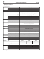
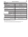
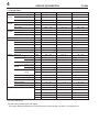
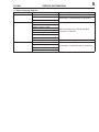
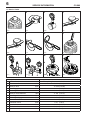
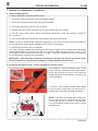
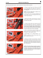
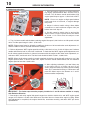
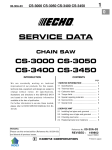
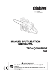
1
CS-680
01-67G-00
0
SERVICE DATA
CHAIN SAW
CS-680
(Serial number : 36000001 and after)
INTRODUCTION
We are constantly working on technical improvement of our products. For this reason,
technical data, equipment and design are
subject to change without notice. All specifications and directions in this SERVICE
DATA are based on the latest product information available at the time of publication.
ECHO SERVICE MANUAL Ord. 401-23
(Model : CS-6702) contains lots of information for servicing this model.
CONTENTS
page
1 SERVICE INFORMATION .............................. 2
1-1 Specification ............................................... 2
1-2 Technical data ............................................. 3
1-3 Torque limits................................................ 4
1-4 Special repairing materials ......................... 5
1-5 Service limits............................................... 6
1-6 Special tools ............................................... 7
2 CARBURETTOR ADJUSTMENT PROCEDURE .. 8
2-1 General adjusting rules ............................... 8
2-2 Presetting Idle adjust screw, L mixture needle
and H mixture needle ....................................... 8
2-3 Adjusting carburettor................................. 10
Reference No. 01-67G-00
ISSUED:
200901
2
SERVICE INFORMATION
CS-680
1 SERVICE INFORMATION
1-1 Specifications
Dimensions Length
Width
Height
Dry weight*
Engine
Type
Rotation
Displacement
Carburettor
Ignition
mm(in)
mm(in)
mm(in)
kg(lb)
435 (17.13)
236 (9.29)
302 (11.89)
6.6 (14.5)
KIORITZ, air-cooled, two-stroke, single cylinder
Ventilated piston, Semi-automatic decompression
Clockwise as viewed from the output end
cm3(in3)
66.8 (4.076)
50.0 (1.969)
34.0 (1.339)
7.6
Diaphragm horizontal-draught
Walbro HDA-272
15.08 - 19.03 (0.594 - 0.749)
CDI (Capacitor discharge ignition) system
with electronic timing advancer
BPMR7A
Automatic rewind
4.5 x 950 (0.18 x 37.4)
Premixed two-stroke fuel
50 : 1 (2 %)
Minimum 89 octane petrol
ISO-L-EGD (ISO/CD13738), JASO FC/FD
0.64 (21.6)
Centrifugal, 3-shoe slide with 3-tension spring
Automatic with volume adjuster and manual override
0.37 (12.5)
Floating rim
7
3/8
45S58
50S58
60S58
45RS58-3/8E
50RS58-3/8E
60RS58-3/8E
45
50
60
0.058
CARLTON A2LM
OREGON 73LGX
64
72
84
3/8
0.058
Bore
mm(in)
Stroke
mm(in)
Compression ratio
Type
Model
Venturi size-Throttle bore mm(in)
Type
Spark plug
Type
Rope diameter x length mm(in)
Fuel
Type
Mixture ratio
Petrol
Two-stroke air cooled engine oil
Tank capacity
L (U.S.fl.oz.)
Clutch
Type
Guide bar / Saw chain lubrication type
Tank capacity, oil
L (U.S.fl.oz.)
Sprocket
Type
Number of teeth
Pitch
in
Guide bar
Type
Starter
Saw chain
Called length
Gauge
Type
Number of drive links
Pitch
Gauge
* Without guide bar and saw chain.
cm
in
in
in
CS-680
1-2 Technical data
Engine
Idling speed
Operating speed
Wide open throttle speed*
Clutch engagement speed
Compression pressure
3
SERVICE INFORMATION
r/min
r/min
r/min
r/min
2,600 +/- 300
9,500 - 10,000
12,900 - 13,900
3,600 - 4,300
MPa (kgf/cm2) (psi)
0.87 (8.9) (126)
Ignition system
Spark plug gap
mm(in)
Minimum secondary voltage at 1,200 r/min
kV
Secondary coil resistance
kΩ
Pole shoe air gaps
mm(in)
Ignition timing
at 1,500 r/min
°BTDC
at 3,000 r/min
°BTDC
at 8,000 r/min
°BTDC
at 10,000 r/min
°BTDC
Carburettor
Idle adjust screw initial setting
turn in**
L mixture needle initial setting
turns back***
H mixture needle initial setting
turns back***
Test Pressure, minimum
MPa (kgf/cm2) (psi)
Metering lever height
mm(in)
Chain oil discharge volume at 7,000 r/min
mL/min(U.S.fl.oz./min)
0.6 - 0.7 (0.024 - 0.028)
21
1.7 - 2.2
0.30 - 0.40 (0.012 - 0.016)
8
15
24
25
1/2
2 1/4
1 1/8
0.05 (0.5) (7.0)
Flush with diaphragm seat
Adjustable 3 - 13 (0.09 - 0.39)
(Factory set 7.5 mL/min)
BTDC: Before top dead centre.
*With 50 cm guide bar and properly adjusted saw chain.
**Set idle adjust screw to the point that its tip just contacts throttle plate before initial setting.
***Turn L/H mixture needles anticlockwise from point that needle is lightly seated.
4
SERVICE INFORMATION
1-3 Torque limits
Descriptions
Starter Starter pawl
system
Starter centre shaft screw
Starter case
Ignition Magneto rotor (Flywheel)
system
Ignition coil
Spark plug
Fuel
Carburettor
system
Carburettor case
Intake bellows
Clutch Clutch hub
Engine Crankcase
Cylinder
Cylinder cover
Muffler
Muffler bracket
Muffler lid
Others Auto-oiler
Cushion
Front handle
Crankcase
Cushion bracket
Compression Cushion bracket
spring
Crankcase
Compression
Eye plate
spring
Front handle
Brake lever (Hand guard)
Brake cover nut
Ignition switch
Guide bar
Regular bolt, nut and screw
Size
M5
M 5*
M5
M8
M4
M 14
M5
M5
M5
LM 10
M 5†
†
M5
M5
M 5*
M5
M4
M4
M5
M5
M5
M5
M 5*
M 4*
M 5*
M 5*
M5
M 3*
M 10
M8
M3
M4
M5
M6
M8
CS-680
kgf•cm
70 - 110
70 - 110
20 - 35
230 - 270
35 - 50
130 - 170
20 - 40
50 - 70
70 - 110
450 - 550
N•m
7 - 11
7 - 11
2 - 3.5
23 - 27
3.5 - 5
13 - 17
2 - 4
5 - 7
7 - 11
45 - 55
in•lbf
60 - 95
60 - 95
17 - 30
200 - 235
30 - 45
113 - 150
17 - 35
45 - 60
60 - 95
390 - 480
70
70
30
70
35
35
35
70
35
70
50
35
35
35
70
25
6
10
200
6
15
25
45
110
7
7
3
7
3.5
3.5
3.5
7
3.5
7
5
3.5
3.5
3.5
7
2.5
0.6
1
20
0.6
1.5
2.5
4.5
11
60
60
25
60
30
30
30
60
30
60
45
30
30
30
60
22
5
9
175
5
13
22
40
95
-
110
110
50
110
50
50
50
110
50
110
70
50
50
50
110
45
10
30
230
10
25
45
75
150
-
11
11
5
11
5
5
5
11
5
11
7
5
5
5
11
4.5
1
3
23
1
2.5
4.5
7.5
15
LM: Left-hand thread
*Thread locking sealant (See next page)
†
The torque difference between four bolts should not exceed 20 kgf•cm (2N•m, 17in•lbf) per bolt.
-
95
95
35
95
45
45
45
95
45
95
60
45
45
45
95
40
9
25
200
9
22
40
65
130
CS-680
SERVICE INFORMATION
1-4 Special repairing materials
Material
Location
Adhesive
Guide bar stud
Starter centre shaft screw
Brake cover nut
Grease
Auto-oiler worm
Clutch needle bearing
Rubber cushion, inside
Choke knob
Rewind spring
Thread locking sealant
Oil seal inner lips
Starter centre shaft
Chain brake (metal contact part)
Front handle
Compression spring Crankcase
Eye plate
Muffler
Remarks
Loctite #609, ThreeBond 1373 or equivalent
Loctite #222, ThreeBond1342 or equivalent
Lithium based grease or ECHO XTended
Protection TM Lubricant
Molybdenum grease (approx. 1 gram)
Loctite #242, ThreeBond #1324 or equivalent
5
6
SERVICE INFORMATION
CS-680
1-5 Service Limits
A
B
5K253
5K083
E
5K082
K
C
D
5K084
F
5K081
G
5K016
H
5K025
L
5K254
M
P
N
1
5K173
5K174
5K181
2
5K097
3
4
5
6
Description
8
5
A Cylinder bore
B Piston outer diameter
mm (in)
7
0
When plating is worn and aluminium can be seen
10
9
10
Min.
49. 83 (1.962)
C Piston pin bore
Max.
12. 035 (0.4738)
D Piston ring groove
Max.
1. 3
(0.051)
E Piston ring side clearance
Max.
0. 1
(0.004)
F Piston pin outer diameter
Min.
11. 98 (0.4717)
G Piston ring width
Min.
1. 15 (0.045)
H Piston ring end gap
Max.
0. 5
K Con-rod small end bore
Max.
(0.02)
16. 025 (0.6309)
L Crankshaft runout
Max.
0. 01 (0.001)
M Sprocket bore
Max.
14. 07 (0.5539)
N Clutch drum bore
Max.
79. 0
(3.11)
P Sprocket wear limit
Max.
0. 5
(0.02)
11
CS-680
7
SERVICE INFORMATION
1-6 Special tools
2 a = 3 mm
3 a = 4 mm
1
5 b = 4 mm
6 b = 5 mm
4
7
8
b
a
9
10
14
15
11
16
17
12
13
19
20
18
21
22
23
24
50
0
0.4
0.8
1.
Description
Tachometer PET-1000
L-hex wrench (3 mm)
L-hex wrench (4 mm)
Piston stopper
Spring pin tool (4 mm)
Spring pin tool (5 mm)
Piston holder
Piston pin tool
Puller
Puller
Crankcase tool
Bearing tool
Worm puller
Worm inserter
Oil seal tool
Oil seal tool
Pressure rubber plug
Pressure plate
Spark tester
Pressure tester
Pressure tester
Limiter cap tool
Module air gap gauge
Compression gauge
MPa
Part Number
897801-33330
895612-79920
895610-79920
897537-30130
897724-01361
897724-02831
897719-02830
897702-30131
897501-03938
897500-00335
897502-19830
897701-14732
897708-19835
Y089-000040
897727-19830
897726-21430
897826-16131
897827-16131
897800-79931
897803-30133
91024
91019
91004
91037
1.2
Key
1
2
3
4
5
6
7
8
9
10
11
12
13
14
15
16
17
18
19
20
21
22
23
24
Ig
ni
tio
n
#. A
01 ir
4 G
P = ap
/N .
3 G
91 5m a
00 m ug
e
4
0
9
01
91
Used for:
Measuring engine speed to adjust carburettor
Removing and installing hex. socket bolt (M4)
Removing and installing hex. socket bolt (M5)
Locking crankshaft rotation
Removing and installing spring pin (4 mm dia)
Removing and installing spring pin (5 mm dia)
Making piston steady to remove and install piston / rings
Removing and installing piston pin
Removing magneto rotor
Removing auto oiler oil cover
Separating crankcase
Removing and installing ball bearings on crankcase
Removing auto-oiler worm
Installing auto-oiler worm
Installing clutch side oil seal
Installing starter side oil seal
Plugging intake port to test crankcase / cylinder leakages
Plugging intake port to test crankcase / cylinder leakages
Checking ignition system
Testing carburettor leakages
Testing crankcase leakages
Removing and installing limiter cap
Adjusting pole shoe air gaps
Measuring cylinder compression
8
SERVICE INFORMATION
CS-680
2 CARBURETTOR ADJUSTMENT PROCEDURE
2-1 General adjusting rules
A. Before adjustment, check the following items.
1. The correct spark plug must be clean and properly gapped.
2. The air filter element must be clean and properly installed.
3. The muffler exhaust port must be clear of carbon.
4. The fuel lines, tank vent and fuel filter are in good condition and clear of debris.
5. The fuel is fresh ( > 89 octane : RON ) and properly mixed at 50 : 1 with “ISO L-EGD” or “JASO FC/
FD” 2-stroke oil.
6. The recommended bar and chain must be installed, and properly tensioned.
NOTE : In order to achieve proper carburettor adjustment, a 50 cm bar and chain should be installed on
the unit. Otherwise serious engine damage will occur due to overspeeding.
B. Adjustment with limiter caps on carburettor.
Set L and H mixture needles fully anticlockwise. Start and run engine for two minutes alternating engine
speed between WOT for 5 seconds and idle for 5 seconds. Adjust idle speed screw to 2,600 +/- 150
r/min. Adjust H mixture needle with limiter cap to 13,400 +/- 300 r/min. If engine does not run correctly after this adjustment, proceed to the next step 2-2.
IMPORTANT : After adjusting carburettor according to the steps 2-2 and 2-3, the limiter cap(s)
must be installed on L and H mixture needle(s) to comply with Emission Directive.
2-2 Presetting Idle adjust screw, L mixture needle and H mixture needle
Tools Required : Small screwdriver with 2.5 mm
blade, electronic tachometer P/N 897801-33330,
limiter cap removal tool with 2.5 mm left-hand
thread P/N 91019. Parts Required : (2) limiter caps
P/N P003-000010.
1. Turn the L and H mixture needles anticlockwise
to rich side stop to align limiter cap tab (A) with locating slot (B), using 2.5 mm blade screwdriver.
A
A
B
NOTE : If cap tabs (A) misalign with locating slots
(B), the cap cannot be removed and the centre
hole threads will strip. If centre hole threads strip,
use 3 mm diameter thread wood screw to remove
the limiter cap.
B
(continued)
CS-680
SERVICE INFORMATION
9
2-2 Presetting Idle adjust screw, L mixture needle and H mixture needle (continued)
2. Screw 2.5 mm limiter cap removal tool P/N
91019 anticlockwise into centre hole of either limiter cap until tab of the limiter cap just comes out of
the locating slot.
NOTE : DO NOT COMPLETELY REMOVE LIMITER CAP FROM Carburettor!
If the first limiter cap is removed completely, the
second limiter cap can be misaligned while inserting the cap removal tool.
3. Remove the limiter cap removal tool from the
limiter cap by turning the tool clockwise, leaving
the limiter cap in place.
4. Screw 2.5 mm limiter cap removal tool P/N
91019 anticlockwise into centre hole of remaining
limiter cap until the limiter cap is removed from the
mixture needle completely. Remove the limiter cap
from limiter cap removal tool by turning clockwise,
then screw limiter cap removal tool into centre hole
of previous limiter cap to remove completely.
5. Turn L and H mixture needle clockwise until
lightly seated, then turn both mixture needles anticlockwise for initial setting as follows :
L mixture needle : 2 1/4, H mixture needle : 1 1/8
NOTE : If needles are forced during seating, damage to carburettor may occur.
6. Remove air cleaner lid and air filter to expose
the Idle adjust screw and throttle plate. Turn Idle
adjust screw anticlockwise and set the screw until
the tip just contacts the throttle plate. Then turn
Idle adjust screw 1/2 turns clockwise. Reinstall air
filter, and cleaner lid.
NOTE : The initial carburettor settings for Idle adjust screw, Idle and Hi speed mixture needles are
intended to start and run the engine before final
carburettor adjustments are made through this
procedure. The actual number of turns needed for
engine operation may vary.
10
SERVICE INFORMATION
CS-680
2-3 Adjusting carburettor
1. Start and warm engine for 1 minute alternating engine speed between WOT and idle every 5
seconds. Turn H mixture needle anticlockwise until
engine speed drops to approx. 11,500 r/min at WOT.
Idle adjust screw
NOTE : Do not run engine at high speed without
load longer than 10 seconds, or engine damage
may occur.
2. Adjust L mixture needle using 2.5mm blade
screwdriver to reach maximum engine r/min just
before lean r/min drop off.
H mixture needle
L mixture needle
3. Set idle speed to 3,600 r/min by turning Idle
adjust screw. Engine speed should be stable
at 3,600 +/- 50 r/min after idle adjust screw
adjustment.
4. Turn L mixture needle anticlockwise reducing engine idle speed 1,000 r/min to set idle speed at 2,600
r/min. The idle speed range is 2,500 - 2,700 r/min.
NOTE : Engine speed must be allowed to stabilize a minimum of 20 seconds after each adjustment of L
mixture needle to assure accurate tachometer readings.
5. Before adjustment, WOT engine speed should be 11,500 r/min or less. If r/min is higher, turn H mixture
needle anticlockwise until 11,500 r/min is achieved. To make the final WOT engine speed adjustment, turn
the H mixture needle clockwise in 1/8 turn increments with the engine at idle. After each adjustment, accelerate to WOT, and check r/min. The final r/min should fall within 13,000 - 13,800 r/min.
NOTE : When the H mixture needle is turned completely clockwise, the engine will continue to run. If the
engine speed at WOT is above 14,300 r/min, adjust H mixture needle anticlockwise and set maximum
engine speed at less than 13,900 r/min.
6. After adjusting carburettor, put new limiter cap
on the other side (c) of limiter cap tool (C) as
shown. Align the limiter cap’s tabs (A) with locating
slots (B) in extended housing of carburettor and
press the limiter caps to the bottoms on L and H
mixture needles respectively.
c
A
B
A
B
C
IMPORTANT : The limiter caps must be properly installed on L and H mixture needles to comply
with Emission Directive.
7. Start engine, and verify engine idle speed ranges from 2,300 to 2,900 r/min, and WOT engine speed
ranges from 12,900 to 13,900 r/min. Make sure the chain does not rotate when engine is idling. When
final adjustment is completed, the engine should idle, accelerate smoothly, and attain WOT per above
specifications.