1
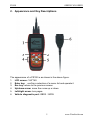
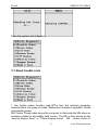
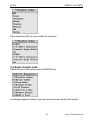
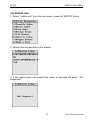
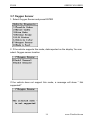
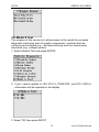
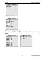
PS100
OBDII/CAN OBDII
Table of Contents
Safety Precautions…………….……….…………..…………..2
Tool Description……….………..……………………….……..4
1. Function…………………..……….……………………….…..4
2. Main features………………………..…..……….……………4
3. Appearance and Key Descriptions………………….……….5
Operation Instructions……………….....……………………..6
1. Preparation for Testing…………….………….……………..6
2. Connect the PS100……………….…………..……………….7
3. Diagnose………………..…………..…..…………...…………7
3.1 Read trouble code…………………..…….………….…8
3.2 Erase trouble code.…….…..………….………..……..10
3.3 Live data………………………………..………….……11
3.4 Freeze Frame…………………..……………….……..12
3.5 IM Status…………………………………………….….14
3.6 Vehicle info………………..…………………………...15
3.7 Oxygen Sensor……………………………………..…..16
3.8 Model 6 Test…………………………………….……..18
3.9 EVAP System Test………………………..…………....20
4. Language……………………………………………………..20
5. Contrast adaptation……………………………..………..….21
6. Lcd test…………………..………………………………...….21
7. Key testing…………………………………………………….22
8. Information…………………………………………..………..22
9. Location of DLC…………………………………………..…..22
APPENDIX A…………...………..…………….………………..23
APPENDIX B………….………..……………………………….25
APPENDIX C………………………………..…..………………26
1
www.Xtooltech.com
PS100
OBDII/CAN OBDII
Safety Precautions
To avoid body hurt, damage to the device and to your cars, please
read the using instruction of PS100 carefully before you use the
device.
The common testing process introduced by this instruction is described by
the experienced technology service people, many of which require you to
take action to avoid possible body hurt, damage to the device or to your car.
Please read your car amending instructions and do as it instructs as to
ensure safety before or during you test. Please keep attention to the
following safety precautions.
z When engine running, it generates CO and other poisonous kinds of
air. To avoid severe hurt or damage caused by them, please test in a
well-ventilated place.
z Please wear qualified eye-protecting goggle to avoid your eyes from
being hurt by the pushed things or harmful fluid.
z When engine running, many parts, for example, coolant fan, pulley and
belts of the fan, rotating in high speed. To avoid this kind of hurt, keep
caution of these parts. Keep in a safe distance from them and other
potentially moving and harmful things.
z When engine running, the parts of the engine become very hot. To
avoid being heated and even burned, please avoid touching with the
parts.
z Ensure well install the braking before you test the engine or test the
car.. Turn to transmission block (automatic transmission) or neutral
transmission (manual transmission).Setback car wheels by proper
means.
z When the car is ignited, connecting or disconnecting the device to or
from the car could destroy the device or car’s electronic parts.
Therefore, please disconnect the tool from vehicle’s DLC socket before
connecting PS100 or disconnection the PS100.
z To not to destroy the on-board computer, you’d have to use a
one-number multimeter with at least 10meg impedance when taking
vehicle electrical measurements.。
z Fuel and battery vapor are highly flammable. To prevent an explosion,
keep all sparks, heated items and open flames untouched with the
battery, fuel or fuel vapor. Don’t smoke near the testing location.
www.Xtooltech.com
2
PS100
z
OBDII/CAN OBDII
When working with the engine running, please don’t wear loose
clothing or any jewelry because loose clothing can be easily caught by
the fan, pulley or belts, while jewelry is highly conductive and they can
cause burning hurt once they make contacts between the ground and
conductive items.
3
www.Xtooltech.com
PS100
OBDII/CAN OBDII
1
Tool Description
1. Function
z
z
z
z
z
z
z
z
PS100 has the following powerful functions:
Works on all 1996 and newer cars & light trucks that are OBD II
compliant (including the VPW, PWM, ISO, KWP 2000 and CAN
protocols)
Reads and clears generic and manufacturer specific Diagnostic
Trouble Codes (DTCs)
Reading Freeze Frame Data
Testing I/M Reading Status
Reading vehicle info
Oxygen sensor test
Model 6 test
EVAP System Test
2. Main features
z
Display: Backlit LCD,160*160 pixel display.
z
Operating Temperature: 0 to 50℃ (﹣32 to 122℉)
z
External Power: 10.0 to 15.5 vols provided via vehicle battery
z
Dimensions: 225mm Length 98mm Width 36mm Height
z
OBDII connector , 1500mm(59.99”)
4
www.Xtooltech.com
PS100
OBDII/CAN OBDII
2. Appearance and Key Descriptions
The appearance of a PS100 is as shown in the above figure.
1. LCD screen: 160*160
2. Enter key: confirm a selection of a menu list and operate it
3. Esc key: retune to the previous screen
4. Up/down arrow: move the curse up or down
5. Left/right arrow: turn pages
6. Vehicle diagnostic port: OBDII -16PIN
5
www.Xtooltech.com
PS100
OBDII/CAN OBDII
Operation Instructions
1. Preparation for Testing
PS100 can test cars and delete error codes while read the error codes.
Meanwhile, there are mechanical problems, such as poor engine
performance due to lower fuel level, soft cubes damaged, electrical wire
or electrical connections, which will also cause faked error codes.
Therefore, you need to refer to car service pamphlet for more details
before you test the known mechanical problems.
Please check the following items before any test.
z Check the engine, power steering fluid, transmission oil (if applicable),
engine coolant fluid and other fluid level. If needed, decrease low fluid
levels.
z Ensure air filter is clear and in good condition. Ensure all air filter
connectors run properly. Check air filter for holes, rips and cracks.
z Ensure engine belts running well. Check there are not ripped, broken,
brittle, loose or lost belts.
z Make sure engine sensor (throttle, gearshift position, transmission,
etc.) is safe and mechanically right connected. Refer to the location
of car service manual.
z Make sure engine sensor (throttle, gearshift position, transmission,
etc.) is safe and mechanically right connected. Refer to the location
of car service manual.
z Ensure all spark plugs are clean and in good condition. Check if there
are damaged, loose, disconnected or lost spark plug wires.
z Ensure battery terminals are clean and tightly connected. Check if
there are corroded or damaged connectors. Ensure that the battery
and the charging voltages are properly applied.
z Check all electrical wires and harasses are correctly connected.
Ensure all insulations are in good condition without bared wires.
z Ensure the engine mechanically sounds. If necessary, perform a
compression test, engine vacuum test, timing test (if applicable) and
etc.
6
www.Xtooltech.com
PS100
OBDII/CAN OBDII
2. Connect the PS100
2.1 Turn the ignition on.
2.2 Locate the vehicle's 16-pin Data Link Connector (DLC).
2.3 Connect the PS100 cable connector to the vehicle’s DLC. Turn on
the ignition, The PS100 will auto start, the following screen will be
displayed.
z
z
z
z
z
z
[Diagnose]: Diagnose
[Language]: To select language
[Contrast]: contrast value modification
[Display Test]: Lcd test
[Keypad Test]:key test
[Information]:show edition information
3. Diagnose
Choose [Diagnose] and then press [Enter] key. The following menu will be
displayed on the screen.
Press ENTER key and it displays.
7
www.Xtooltech.com
PS100
OBDII/CAN OBDII
Enter the system and it displays:
3-1 Read trouble code
1. the trouble codes function read DTCs from the vehicle's computer
modules there tow types of codes, Malfunction Indicator Lamp(MIL) Codes
and pending codes
MIL Codes: These codes cause the computer to illuminate the MIL when an
emission related or driveability fault occurs. The MIL is also known as the
“service Engine Soon” or “Check Engine Lamp”. MIL codes remain in
8
www.Xtooltech.com
PS100
OBDII/CAN OBDII
the vehicle’s memory until the fault is repaired.
2. Pending Codes: These codes are also referred as “continuous monitor”
and “maturing codes”. An intermittent fault will cause the computer to store
a code in memory. If the fault does not occur within 40 warm-up cycles, the
code will be cleared from memory. If the fault occurs a specific number of
times, the code will mature into a DTC and the MIL will turn on.
3. Select Trouble codes and press ENTER, The PS100 retrives the DTCs
stored in the vehicle's computer modules.
▲
▲
if there are no trouble codes, it will display “No codes in the vehicle!”
If there are any trouble codes, all information will be reported on the
display
Select one of the error codes if there are over 2 error codes by moving
up/down key.
If there are factory definition error codes the relative information will be
reported on the display,You can select the corresponding car model to
make sense of the error codes.
9
www.Xtooltech.com
PS100
OBDII/CAN OBDII
Take operating GM car error codes for example.
3-2 Erase trouble code
Select Erase Codes and press the ENTER key.
a message appears asking if you are want to erase all the fault codes.
10
www.Xtooltech.com
PS100
OBDII/CAN OBDII
If you Press ENTER
3-3 Live data
1.Display the live data,
11
www.Xtooltech.com
PS100
OBDII/CAN OBDII
2. Live data are reported on the display
3. Using the LEFT /RIGHT arrows to view Live data of the following page
monitors.
Abbreviated Name for live data specified in Appendix A
3-4 Freeze Frame
1. when an emission-related fault occurs, certain vehicle conditions are
recorded by the on-board computer. this information is referred to as a
freeze.
Frame data. this data can be overwriten by faults with a higher priority.
2. if codes were erased, the freeze frame data may not be stored in vehicle
memory.
Select Freeze Frame from the menu and press ENTER
12
www.Xtooltech.com
PS100
OBDII/CAN OBDII
3. Freeze Frame data are reported on the display
4. Using the LEFT /RIGHT arrows to view Live data of the following page
monitors.
Abbreviated Name for Freeze Frame specified in Appendix A
13
www.Xtooltech.com
PS100
OBDII/CAN OBDII
3-5 IM Status
1. Select I/M Status and press ENTER
2. Using the UP/DOWN arrows to view status of the following monitors.
Abbreviated Name
-Misfire Monitor
-FUEL System Mon
-Com Component
-Catalyst Mon
-Htd Catalyst
-Evap System Mon
-Sec Air System
-A/C Refrig Mon
-OXYGEN Sens Mon
-Oxygen Sens HTR
-EGR System Mon
Expanded Name
Misfire monitor
Fuel System Monitor
Comprehensive Components Monitor
Catalyst Monitor
Heated Catalyst Monitor
Evaporative System Monitor
Secondary Air System Monitor
Air Conditioning Refrigerant Monitor
Oxygen Sensor Monitor
Oxygen Heater Sensor Monitor
Exhaust Gas Recirculation System Monitor
14
www.Xtooltech.com
PS100
OBDII/CAN OBDII
3-6 Vehicle info
1. Select “Vehicle info” from the main menu, press the “ENTER” button.
2. Vehicle info are reported on the display.
3. If the vehicle does not support this mode, a message will show " Not
supported!"
15
www.Xtooltech.com
PS100
OBDII/CAN OBDII
3-7 Oxygen Sensor
1. Select Oxygen Sensor and press ENTER
2. If the vehicle supports this mode, data reported on the display. You can
select Oxygen sensor location
If the vehicle does not support this mode, a message will show " Not
supported!"
16
www.Xtooltech.com
PS100
OBDII/CAN OBDII
If your vehicle applies to CAN protocol, a message will show.
3. Select Oxygen sensor test id.
Abbreviated Name
Expanded Name
RichToLeSeThV(Con)
Rich to lean sensor threshold voltage (constant)
LeanToRiSeThV(Con)
Lean to rich sensor threshold voltage (constant)
LowSeVFoSwTiCA(Con)
Low sensor voltage for switch time calculation (constant)
HighSeVoFoSwTiCa(Con)
High sensor voltage for switch time calculation (constant)
RichToLeSwTi(Cal)
Rich to lean sensor switch time (calculated)
LeanToRiSeSwTi(Cal)
Lean to rich sensor switch time (calculated)
MinSeVoForTeCy(Cal)
Minimum sensor voltage for test cycle (calculated)
MaxSeVoForTeCy(Cal)
Maximum sensor voltage for test cycle (calculated)
TimeBeSeTr(Cal)
Time between sensor transitions (calculated)
Sensor period(Cal)
Sensor period (calculated)
4. Disp test result.
17
www.Xtooltech.com
PS100
OBDII/CAN OBDII
3-8 Model 6 Test
The purpose of this service is to allow access to the results for on-board
diagnostic monitoring tests of specific components / systems that are
continuously monitored (e.g., mis-firemonitoring) and non-continuously
monitored (e.g., catalyst system).
1. Select Model 6 Test and press ENTER
2. If your vehicle applies to ISO 9141-2, PWM,VPW, and ISO 14230-4,
information will be reported on the display
3. Select TID ,then press ENTET
18
www.Xtooltech.com
PS100
OBDII/CAN OBDII
4. Disp test result.
TID specified in Appendix B
If your vehicle applies to ISO 15765-4, information will be reported on the
display
19
www.Xtooltech.com
PS100
OBDII/CAN OBDII
OBDMID and CID specified in Appendix C.
3-9 EVAP System Test
FUNCTIONAL DESCRIPTION—The purpose of this service is to enable
the external test equipment to control the operation of an on-board system,
test or component.
1. Select EVAP System Test and press ENTER
2. There are the following three kinds of test results.
a) If it does not support this function, it will show.
20
www.Xtooltech.com
PS100
OBDII/CAN OBDII
b) If the conditions are not proper to run the test, the vehicle, d"The
conditions are not proper to run the test" will display.
c) If test succeeds, it shows "Command Sent"
4. Language
Choose [language] at the main menu. Then press [Enter]. The screen will
display as the following
5. Contrast Adaptation
Choose [Contrast] at the main menu. Then press [Enter]. The screen will
display as the following.
21
www.Xtooltech.com
PS100
OBDII/CAN OBDII
Simply press up/down arrow to set and then press [Enter] to confirm.
6. Lcd test
Choose[Lcd Test] at the main menu, Press Enter],The screen will display
the following dynamic image.
7. Key testing
Choose [Keypad Test] at the main menu. Press [Enter]. The screen will
display the following interface.
Press any key then the screen will flash due to corresponding to your
cooperation. Double [Esc], you can withdraw from the testing.
8. Information
Choose [About] and then press [Enter]. Then screen will display the version
of this device.
22
www.Xtooltech.com
PS100
OBDII/CAN OBDII
9. Location of DLC
OBD-II 16pin is like the following picture shows. For VW Golf, it usually
locates at the right hand direction steering column. For Jetta, it usually
locates in the cab on the left bellow the instruction dash; For SANTANA,
it locates at the transmission dust cover which is in the front of it.. For
more details, please refer to car repairing pamphlet
APPENDIX A
Abbreviated NAME FOR SERVICE $01 AND $02 SCALING
AND DEFINITION
Abbreviated Name
Expanded Name
Fuel Sys1, Fuel Sys2
Fuel system 1 status, Fuel system 1 status:
CALC LOAD
Calculated LOAD Value
COOLANT
Engine Coolant Temperature
ST FTRM1
Short Term Fuel Trim - Bank 1
LT FTRM1
Long Term Fuel Trim - Bank 1
ST FTRM2
Short Term Fuel Trim - Bank 2
LT FTRM2
Long Term Fuel Trim – Bank 2
FUEL PRES
Fuel Rail Pressure (gauge)
MAP
Intake Manifold Absolute Pressure
ENGINE
Engine RPM
VEH SPEED
Vehicle Speed Sensor
IGN ADV
Ignition Timing Advance for #1 Cylinder
IAT
Intake Air Temperature
MAF
Air Flow Rate from Mass Air Flow Sensor
ABSLT TPS
Absolute Throttle Position
SECOND AIR
Commanded Secondary Air Status
23
www.Xtooltech.com
PS100
OBDII/CAN OBDII
O2S Location
Location of Oxygen Sensors
O2S11
Bank 1 – Sensor 1
O2S12
Bank 1 – Sensor 2
O2S13
Bank 1 – Sensor 3
O2S14
Bank 1 – Sensor 4
O2S21
Bank 2 – Sensor 1
O2S22
Bank 2 – Sensor 2
O2S23
Bank 2 – Sensor 3
O2S24
Bank 2 – Sensor 4
SHRTFT11
Short Term Fuel Trim (Bank 1 – Sensor 1)
SHRTFT12
Short Term Fuel Trim (Bank 1 – Sensor 2)
SHRTFT13
Short Term Fuel Trim (Bank 1 – Sensor 3)
SHRTFT14
Short Term Fuel Trim (Bank 1 – Sensor 4)
SHRTFT11
Short Term Fuel Trim (Bank 2 – Sensor 1)
SHRTFT12
Short Term Fuel Trim (Bank 2 – Sensor 2)
SHRTFT13
Short Term Fuel Trim (Bank 2 – Sensor 3)
SHRTFT14
Short Term Fuel Trim (Bank 2 – Sensor 4)
OBD2 STAT
OBD requirements to which vehicle is designed
PTO STATUS
Power Take Off (PTO) Status
MI Dist. Traveled
Distance Travelled While MIL is Activated
O2S W.R.
EQ_RAT11
O2S W.R.
B1,S1
Bank 1 – Sensor 1 (wide range O2S) Equivalence Ratio (lambda)
Bank 1 – Sensor 1 (wide range O2S) Oxygen Sensor Voltage
O2S W.R.
EQ_RAT12
Bank 1 – Sensor 2 (wide range O2S) Equivalence Ratio (lambda)
O2S W.R.
B1,S2
Bank 1 – Sensor 2 (wide range O2S) Oxygen Sensor Voltage
O2S W.R.
EQ_RAT13
Bank 1 – Sensor 3 (wide range O2S) Equivalence Ratio (lambda)
O2S W.R.
B1,S3
Bank 1 – Sensor 3 (wide range O2S) Oxygen Sensor Voltage
O2S W.R.
EQ_RAT14
Bank 1 – Sensor 4 (wide range O2S) Equivalence Ratio (lambda)
O2S W.R.
B1,S4
Bank 1 – Sensor 4 (wide range O2S) Oxygen Sensor Voltage
O2S W.R.
EQ_RAT21
Bank 2 – Sensor 1 (wide range O2S) Equivalence Ratio (lambda)
O2S W.R.
B2,S1
Bank 2 – Sensor 1 (wide range O2S) Oxygen Sensor Voltage
O2S W.R.
EQ_RAT22
Bank 2 – Sensor 2 (wide range O2S) Equivalence Ratio (lambda)
O2S W.R.
B2,S2
Bank 2 – Sensor 2 (wide range O2S) Oxygen Sensor Voltage
O2S W.R.
EQ_RAT23
Bank 2 – Sensor 3 (wide range O2S) Equivalence Ratio (lambda)
O2S W.R.
B2,S3
Bank 2 – Sensor 3 (wide range O2S) Oxygen Sensor Voltage
O2S W.R.
EQ_RAT24
Bank 2 – Sensor 4 (wide range O2S) Equivalence Ratio (lambda)
O2S W.R.
B2,S4
Bank 2 – Sensor 4 (wide range O2S) Oxygen Sensor Voltage
O2S W.R.
EQ_RAT11
Bank 1 – Sensor 1 (wide range O2S) Equivalence Ratio (lambda)
O2S W.R.
B1,S1
Bank 1 – Sensor 1 (wide range O2S) Oxygen Sensor Voltage
O2S W.R.
EQ_RAT12
Bank 1 – Sensor 2 (wide range O2S) Equivalence Ratio (lambda)
//24-2b
0x1d
O2S W.R.
B1,S2
Bank 1 – Sensor 2 (wide range O2S) Oxygen Sensor Voltage
O2S W.R
EQ_RAT13
Bank 2 – Sensor 1 (wide range O2S) Equivalence Ratio (lambda)
24
www.Xtooltech.com
PS100
OBDII/CAN OBDII
O2S W.R.
B1,S3
Bank 2 – Sensor 1 (wide range O2S) Oxygen Sensor Voltage
O2S W.R.
EQ_RAT14
Bank 2 – Sensor 2 (wide range O2S) Equivalence Ratio (lambda)
O2S W.R.
B1,S4
Bank 2 – Sensor 2 (wide range O2S) Oxygen Sensor Voltage
O2S W.R.
EQ_RAT21
Bank 3 – Sensor 1 (wide range O2S) Equivalence Ratio (lambda)
O2S W.R.
B2,S1
Bank 3 – Sensor 1 (wide range O2S) Oxygen Sensor Voltage
O2S W.R.
EQ_RAT22
Bank 3 – Sensor 2 (wide range O2S) Equivalence Ratio (lambda)
O2S W.R.
B2,S2
Bank 3 – Sensor 2 (wide range O2S) Oxygen Sensor Voltage
O2S W.R.
EQ_RAT23
Bank 4 – Sensor 1 (wide range O2S) Equivalence Ratio (lambda)
O2S W.R.
B2,S3
Bank 4 – Sensor 1 (wide range O2S) Oxygen Sensor Voltage
O2S W.R.
EQ_RAT24
Bank 4 – Sensor 2 (wide range O2S) Equivalence Ratio (lambda)
O2S W.R.
B2,S4
Bank 4 – Sensor 2 (wide range O2S) Oxygen Sensor Voltage
O2S W.R.
EQ_RAT11
Bank 1 – Sensor 1 (wide range O2S) Equivalence Ratio (lambda)
O2S W.R.
B1,S1
Bank 1 – Sensor 1 (wide range O2S) Oxygen Sensor Current
O2S W.R.
EQ_RAT12
Bank 1 – Sensor 2 (wide range O2S) Equivalence Ratio (lambda)
O2S W.R.
B1,S2
Bank 1 – Sensor 2 (wide range O2S) Oxygen Sensor Current
O2S W.R.
EQ_RAT13
Bank 1 – Sensor 3 (wide range O2S) Equivalence Ratio (lambda)
O2S W.R.
B1,S3
Bank 1 – Sensor 3 (wide range O2S) Oxygen Sensor Current
O2S W.R.
EQ_RAT14
Bank 1 – Sensor 4 (wide range O2S) Equivalence Ratio (lambda)
O2S W.R.
B1,S4
Bank 1 – Sensor 4 (wide range O2S) Oxygen Sensor Current
O2S W.R
EQ_RAT21
Bank 2 – Sensor 1 (wide range O2S) Equivalence Ratio (lambda)
O2S W.R
B2,S1
Bank 2 – Sensor 1 (wide range O2S) Oxygen Sensor Current
O2S W.R.
EQ_RAT22
Bank 2 – Sensor 2 (wide range O2S) Equivalence Ratio (lambda)
O2S W.R.
B2,S2
Bank 2 – Sensor 2 (wide range O2S) Oxygen Sensor Current
O2S W.R.
EQ_RAT23
Bank 2 – Sensor 3 (wide range O2S) Equivalence Ratio (lambda)
O2S W.R.
B2,S3
Bank 2 – Sensor 3 (wide range O2S) Oxygen Sensor Current
O2S W.R.
EQ_RAT24
Bank 2 – Sensor 4 (wide range O2S) Equivalence Ratio (lambda)
O2S W.R.
B2,S4
Bank 2 – Sensor 4 (wide range O2S) Oxygen Sensor Current
O2S W.R.
EQ_RAT11
Bank 1 – Sensor 1 (wide range O2S) Equivalence Ratio (lambda)
O2S W.R.
B1,S1
Bank 1 – Sensor 1 (wide range O2S) Oxygen Sensor Current
O2S W.R.
EQ_RAT12
Bank 1 – Sensor 2 (wide range O2S) Equivalence Ratio (lambda)
O2S W.R.
B1,S2
Bank 1 – Sensor 2 (wide range O2S) Oxygen Sensor Current
O2S W.R.
EQ_RAT21
Bank 2 – Sensor 1 (wide range O2S) Equivalence Ratio (lambda)
O2S W.R.
B2,S1
Bank 2 – Sensor 1 (wide range O2S) Oxygen Sensor Current
O2S W.R.
EQ_RAT22
Bank 2 – Sensor 2 (wide range O2S) Equivalence Ratio (lambda)
O2S W.R.
B2,S2
Bank 2 – Sensor 2 (wide range O2S) Oxygen Sensor Current
O2S W.R
EQ_RAT31
Bank 3 – Sensor 1 (wide range O2S) Equivalence Ratio (lambda)
O2S W.R
B3,S1
Bank 3 – Sensor 1 (wide range O2S) Oxygen Sensor Current
O2S W.R.
EQ_RAT32
Bank 3 – Sensor 2 (wide range O2S) Equivalence Ratio (lambda)
O2S W.R.
B3,S2
Bank 3 – Sensor 2 (wide range O2S) Oxygen Sensor Current
O2S W.R.
EQ_RAT41
Bank 4 – Sensor 1 (wide range O2S) Equivalence Ratio (lambda)
O2S W.R.
B4,S1
Bank 4 – Sensor 1 (wide range O2S) Oxygen Sensor Current
O2S W.R.
EQ_RAT42
Bank 4 – Sensor 2 (wide range O2S) Equivalence Ratio (lambda)
O2S W.R.
B4,S2
Bank 4 – Sensor 2 (wide range O2S) Oxygen Sensor Current
25
www.Xtooltech.com
PS100
OBDII/CAN OBDII
APPENDIX B
This applies to ISO 9141-2, SAE J1850, and ISO 14230-4
definition for service $06.
TID(TEST ID SCALING DESCRIPTION)
$01 Rich to lean sensor threshold voltage (constant)
$02 Lean to rich sensor threshold voltage (constant)
$03 Low sensor voltage for switch time calculation (constant)
$04 High sensor voltage for switch time calculation (constant)
$05 Rich to lean sensor switch time (calculated)
$06 Lean to rich sensor switch time (calculated)
$07 Minimum sensor voltage for test cycle (calculated)
$08 Maximum sensor voltage for test cycle (calculated)
$09 Time between sensor transitions (calculated)
$0A Sensor period (calculated)
$0B-$1F reserved - to be specified by SAE and/or ISO
$21-$2F manufacturer Test ID description
$30-$3F manufacturer Test ID description
$41-$4F manufacturer Test ID description
$50-$5F manufacturer Test ID description
$61-$6F manufacturer Test ID description
$70-$7F manufacturer Test ID description
$81-$9F manufacturer Test ID description
$A1-$BF manufacturer Test ID description
$C1-$DF manufacturer Test ID description
$E1-$FF manufacturer Test ID description
APPENDIX C
This only applies to ISO 15765-4 definition for service $06
OBDMID (ON-BOARD DIAGNOSTIC MONITOR ID)
DEFINITION FOR SERVICE $06
OBDMID (Hex) On-Board Diagnostic Monitor ID name
00 OBD Monitor IDs supported ($01 - $20)
01 Oxygen Sensor Monitor Bank 1 - Sensor 1
02 Oxygen Sensor Monitor Bank 1 - Sensor 2
03 Oxygen Sensor Monitor Bank 1 - Sensor 3
04 Oxygen Sensor Monitor Bank 1 - Sensor 4
05 Oxygen Sensor Monitor Bank 2 - Sensor 1
06 Oxygen Sensor Monitor Bank 2 - Sensor 2
07 Oxygen Sensor Monitor Bank 2 - Sensor 3
26
www.Xtooltech.com
PS100
OBDII/CAN OBDII
08 Oxygen Sensor Monitor Bank 2 - Sensor 4
09 Oxygen Sensor Monitor Bank 3 - Sensor 1
0A Oxygen Sensor Monitor Bank 3 - Sensor 2
0B Oxygen Sensor Monitor Bank 3 - Sensor 3
0C Oxygen Sensor Monitor Bank 3 - Sensor 4
0D Oxygen Sensor Monitor Bank 4 - Sensor 1
0E Oxygen Sensor Monitor Bank 4 - Sensor 2
0F Oxygen Sensor Monitor Bank 4 - Sensor 3
10 Oxygen Sensor Monitor Bank 4 - Sensor 4
11 - 1F Reserved by document for future standardization
20 OBD Monitor IDs supported ($21 - $40)
21 Catalyst Monitor Bank 1
22 Catalyst Monitor Bank 2
23 Catalyst Monitor Bank 3
24 Catalyst Monitor Bank 4
25 – 30 Reserved by document for future standardization
31 EGR Monitor Bank 1
32 EGR Monitor Bank 2
33 EGR Monitor Bank 3
34 EGR Monitor Bank 4
35 - 38 Reserved by document for future standardization
39 EVAP Monitor (Cap Off)
3A EVAP Monitor (0.090")
3B EVAP Monitor (0.040”)
3C EVAP Monitor (0.020”)
3D Purge Flow Monitor
3E - 3F Reserved by document for future standardization
40 OBD Monitor IDs supported ($41 - $60)
41 Oxygen Sensor Heater Monitor Bank 1 - Sensor 1
42 Oxygen Sensor Heater Monitor Bank 1 - Sensor 2
43 Oxygen Sensor Heater Monitor Bank 1 - Sensor 3
44 Oxygen Sensor Heater Monitor Bank 1 - Sensor 4
45 Oxygen Sensor Heater Monitor Bank 2 - Sensor 1
46 Oxygen Sensor Heater Monitor Bank 2 - Sensor 2
47 Oxygen Sensor Heater Monitor Bank 2 - Sensor 3
48 Oxygen Sensor Heater Monitor Bank 2 - Sensor 4
49 Oxygen Sensor Heater Monitor Bank 3 - Sensor 1
4A Oxygen Sensor Heater Monitor Bank 3 - Sensor 2
4B Oxygen Sensor Heater Monitor Bank 3 - Sensor 3
4C Oxygen Sensor Heater Monitor Bank 3 - Sensor 4
4D Oxygen Sensor Heater Monitor Bank 4 - Sensor 1
4E Oxygen Sensor Heater Monitor Bank 4 - Sensor 2
4F Oxygen Sensor Heater Monitor Bank 4 - Sensor 3
50 Oxygen Sensor Heater Monitor Bank 4 - Sensor 4
27
www.Xtooltech.com
PS100
OBDII/CAN OBDII
51 - 5F Reserved by document for future standardization
60 OBD Monitor IDs supported ($61 - $80)
61 Heated Catalyst Monitor Bank 1
62 Heated Catalyst Monitor Bank 2
63 Heated Catalyst Monitor Bank 3
64 Heated Catalyst Monitor Bank 4
65 - 70 Reserved by document for future standardization
71 Secondary Air Monitor 1
72 Secondary Air Monitor 2
73 Secondary Air Monitor 3
74 Secondary Air Monitor 4
75 - 7F Reserved by document for future standardization
80 OBD Monitor IDs supported ($81 - $A0)
81 Fuel System Monitor Bank 1
82 Fuel System Monitor Bank 2
83 Fuel System Monitor Bank 3
84 Fuel System Monitor Bank 4
85 - 9F Reserved by document for future standardization
A0 OBD Monitor IDs supported ($A1 - $C0)
A1 Mis-Fire Monitor General Data
A2 Mis-Fire Cylinder 1 Data
A3 Mis-Fire Cylinder 2 Data
A4 Mis-Fire Cylinder 3 Data
A5 Mis-Fire Cylinder 4 Data
A6 Mis-Fire Cylinder 5 Data
A7 Mis-Fire Cylinder 6 Data
A8 Mis-Fire Cylinder 7 Data
A9 Mis-Fire Cylinder 8 Data
AA Mis-Fire Cylinder 9 Data
AB Mis-Fire Cylinder 10 Data
AC Mis-Fire Cylinder 11 Data
AD Mis-Fire Cylinder 12 Data
AE - BF Reserved by document for future standardisation
C0 OBD Monitor IDs supported ($C1 - $E0)
C1 - DF Reserved by document for future standardisation
E0 OBD Monitor IDs supported ($E1 - $FF)
E1 - FF Vehicle Manufacturer defined OBDM IDs
TID(STANDARDIZED TEST ID DESCRIPTION)
Range (Hex) Description
00 Reserved by document
01 Rich to lean sensor threshold voltage (constant)
02 Lean to rich sensor threshold voltage (constant)
03 Low sensor voltage for switch time calculation (constant)
28
www.Xtooltech.com
PS100
OBDII/CAN OBDII
04 High sensor voltage for switch time calculation (constant)
05 Rich to lean sensor switch time (calculated)
06 Lean to rich sensor switch time (calculated)
07 Minimum sensor voltage for test cycle (calculated)
08 Maximum sensor voltage for test cycle (calculated)
09 Time between sensor transitions (calculated)
0A Sensor period (calculated)
0B EWMA(Exponential Weighted Moving Average)misfire counts for last 10 driving cycles
(calculated)
Calculation: 0.1 * (current counts) + 0.9 * (previous average)
Initial value for (previous average) = 0
0C Misfire counts for last/current driving cycles (calculated)
0D - 7F Reserved for future standardisation
29
www.Xtooltech.com