1
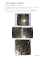
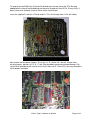
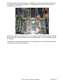
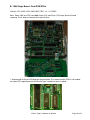
TYPE#1
USB Consult Hardware Installation Manual V3.5
(JECS ECCS 1984-1989 Legacy Engine Control Units,
HITACHI ECCS/NICS 1985-1989 Legacy Engine Control Units)
Copyright 2004 - 2012 Nistune Developments
INTRODUCTION
Welcome to Nistune.
The Nistune hardware and software solution provides a means for the car enthusiast to retune
their vehicle whilst retaining their factory ECU and its default programming.
This solution provides many advantages over aftermarket ECUs in that the
•
Factory default tuning is maintained once the Nistune board is installed. Upon installation
of the board, vehicle will be operational as usual.
•
Additional tuning can then be made against the factory maps for modifications made to the
vehicle. There is no need to tune the car to get it running from scratch, reducing time and
costs of tuning required on dyno.
•
There is no need for wiring loom modifications.
Nistune provides realtime tuning and maptracing. It provides the ability to make changes on the fly
to the factory ECU and then the desired results are achieved, save these permanently in nonvolatile memory on the programmable board.
Nistune also provides data logging and playback facilities, the first available for legacy type 1980s
Nissan JECS/Hitachi ECUs. Nistune software also provides a user friendly responsive graphical
interface to perform modifications.
Contained in this manual are the instructions for installing a Nistune board into 1980s Nissan
vehicles.
Nistune Type 1 Hardware Installation
Page 2 of 33
WARNING
If your ECU pulses the fuel pump, injectors, fuel regulator, flashes LEDs randomly (or they
just stay on when they shouldn’t) or your engine does not start then your ECU may not
have your board fitted correctly.
Testing has shown on early Nissan ECUs that this can potentially keep the Mass Airflow
Meter heater element on longer than 1 second and blow it like a fuse.
Check:
•
•
•
Poor connection between the Nistune board and ECU due to failure to secure the
board correctly using hot glue or similar mechanism
Poor header cable connection to the ECU from Nistune board
Mismatched Nistune board configuration for the ECU image you are attempting to
use
How to fix this:
•
•
•
•
Always firstly try ECU with the factory ROM without the Nistune board to attempt to
start the car properly
Ensure your Nistune board has the correct base ROM image loaded for your ECU
Ensure your solder joints are good and header connector is installed correctly
Attempt USB Consult connection to the Nistune board to verify communication
The Nistune diagnostics document covers problem diagnosis in more detail
Nistune Type 1 Hardware Installation
Page 3 of 33
TABLE OF CONTENTS
1.
2.
3.
Removing the ECU ....................................................................................................................... 5
Opening the ECU .......................................................................................................................... 5
Resocketing the ECU.................................................................................................................... 6
A. 1984-1985 Dual Board - Dual ROM ECUs ................................................................................ 7
B. 1986 Single Board - Dual ROM ECUs..................................................................................... 10
C. 1987 Single Board - Single ROM ECUs .................................................................................. 12
D. 1989 Single Board - Single ROM - Header Connector ECUs .................................................. 13
4. CPU Header Connector Installation (X1) .................................................................................... 16
A. Early Model ECUs ................................................................................................................... 17
B. Later Model ECUs ................................................................................................................... 18
5. USB Connector Installation (X2) ................................................................................................. 22
6. Inserting the Board...................................................................................................................... 24
7. Securing the Board ..................................................................................................................... 26
8. Installing In The Vehicle .............................................................................................................. 27
9. Upgrading ECU MAF hardware................................................................................................... 28
Nistune Type 1 Hardware Installation
Page 4 of 33
1. Removing the ECU
Locate the ECU in vehicle to be modified. The location of the factory ECU can be identified from
the vehicle service manual. Usually for most Nissans the ECU is located in the passenger kick
panel. Disconnect your negative battery terminal prior to removing the ECU. Remove the screws
holding in the mounting bracket. Then slide the ECU out from the kick panel and unplug/unscrew
the connectors.
Below is a picture of the ECU with the mounting bracket removed. If sending the ECU away for
Nistune board installation, please send without the mounting bracket.
2. Opening the ECU
For Nistune board installation, firstly remove the top and bottom lids from the ECU. Screws
require a correctly matched Philips head screw driver as they are usually fitted from factory with a
red or blue epoxy which requires some force in order to remove the screws.
The following chapter is split into different sections, dependent on what ECU you have.
Nistune Type 1 Hardware Installation
Page 5 of 33
3. Resocketing the ECU
IMPORTANT
Nissan ECUs are sprayed with conformal coating at the end of manufacture. This is to protect
digital circuitry from moisture. Remove conformal coating around the chips to be removed from
the ECU before desoldering.
Use Acetone or paint thinner to remove the coating on both sides of the chips, with a hard bristle
brush and cloth to remove excess coating.
This solution should also be used for removing flux after soldering in the ECU socket and CPU
connector to give the ECU a clean finish after installation
After removing the conformal coating then the chips can be desoldered. Ensure that a suitable
desoldering gun is used and that there is a sufficient heat bridge between each soldered pad and
the desoldering gun. Flux or additional solder can be used to create the heat bridge if reuqired
Read our soldering guide for more information
Nistune Type 1 Hardware Installation
Page 6 of 33
A. 1984-1985 Dual Board - Dual ROM ECUs
Vehicles: Early Z31 300ZX and E12 Nissan Exa.
This is a multiboard ECU with a 1K and 8K ROM chip. The two chips need to be removed and
jumpers changed on the board before the Nistune board can be installed.
The ROM images must be read using a special adaptor plugged into an EPROM programmer.
These are then combined into a 16K image and converted into a Nistune ENT file for
programming the board.
Nistune Type 1 Hardware Installation
Page 7 of 33
To remove the two ROM chips (U3 and U4) desolder from the top side of the ECU. Be very
careful with the heat of the desoldering gun because the pads on these ECUs lift very easily. It
doesn't take much to break a track on these earlier circuit boards.
Insert the supplied IC socket in IC3 and solder in. Fill in the through holes if IC4 with solder.
Next remove the four brown jumpers. These are J4, J5, J8 and J10. You can shorten these
existing jumpers positions to J3, J6, J7 and J9 by desoldering one end and repositioning it. Be
careful when desoldering the track to ensure that it does not lift. These ECUs are very old and the
circuit boards are fragile.
Nistune Type 1 Hardware Installation
Page 8 of 33
The below picture shows the removed ICs, installed 28 pin machine drilled socket and four wire
link jumpers installed in their new locations. Existing brown links can be reused into the new
jumper positions in the ECU.
Next remove R15 which is below J9/J10. This is no longer used with the Nistune board installed.
Note that You will no longer be able to use the factory ROM chip in this ECU once these jumpers
are changed.
Installation of the Nistune board now follows the same procedure as for other 6802 based ECUs
in the following sectionf of this document
Nistune Type 1 Hardware Installation
Page 9 of 33
B. 1986 Single Board - Dual ROM ECUs
Vehicles: Z31 300ZX VG30 1986-1987, CR31 / VL / VLT RB30
Note: Some 1986 era ECU have both 28 pin (IC4) and 24 pin (IC5) chips which will need
removing. These chips are located next to each other.
1. Remove both of these ROM chips per picture below. The second smaller ROM is not needed
for normal ECU operation once the Nistune Type 1 board has been installed
Nistune Type 1 Hardware Installation
Page 10 of 33
(a) Single ROM ECU. Only IC4 needs to be removed and replaced with a socket
(b) Dual ROM ECU. Both IC4 and IC5 need to be removed. Jumpered J3 by using a solder blob
between J4 and the J3 pad.
2. Where the 28 pin ROM (IC4) has been removed, replace this with a 28 pin machine drilled
socket.
Note: the orientation of the socket must have the crescent indent facing the same direction of the
previously installed ROM chip
If IC5 was removed, fill in the through holes where the 24 pin ROM was mounted with solder..
3. Use some solder to connect J4 to J3 as seen in the picture above on the Dual ROM ECUs.
This will enable useage of only the 28 pin chip.
4. Verify ECU operation with new socket using only the factory 28 pin ROM chip. The LEDs
should flash when in diagnostic mode, and vehicle should function as normal. If not then
immediately remove power and recheck your soldering
Installation of the Nistune board now follows the same procedure as for other 6802 based ECUs.
Nistune Type 1 Hardware Installation
Page 11 of 33
C. 1987 Single Board - Single ROM ECUs
Vehicles: Z31 300ZX VG30 1987, VL RB30
These ECUs only contain a single chip such as pictured below one 28 pin ROM chip
1. Remove the factory ROM chip, install a 28 pin machine drilled socket
2. Then test that the ECU still works by placing the factory ROM chip in the socket and checking
the vehicle runs and flashes LEDs when in diagnostic mode.
Installation of the Nistune board now follows the same procedure as for other 6802 based ECUs.
Nistune Type 1 Hardware Installation
Page 12 of 33
D. 1989 Single Board - Single ROM - Header Connector ECUs
Vehicles: Z31 VG30 late, HR31 RB20, S13 CA18, A31 RB20, EK10 MA09, S13 KA24E
These ECUs either only contain a single chip such as shown in the pictures below. These contain
a header connector which the Nistune board connects to on this particular ECU.
1989 Z31 VG30E/ET
Nistune Type 1 Hardware Installation
Page 13 of 33
HR31 RB20DET
S13 CA18DE/DET
Nistune Type 1 Hardware Installation
Page 14 of 33
A31 RB20DE/DET
EK10 MA09ERT / S13 KA24E
1. Remove the factory ROM chip, install a 28 pin machine drilled socket
2. Then test that the ECU still works by placing the factory ROM chip in the socket and checking
the vehicle runs and flashes LEDs when in diagnostic mode.
Installation of the Nistune board now follows the same procedure as for other 6802 based ECUs
apart from the header connector.
Nistune Type 1 Hardware Installation
Page 15 of 33
4. CPU Header Connector Installation (X1)
The Nistune board will come supplied with two header connectors. One is for the USB socket and
the other connects to the ECU processor (marked HD6802 or HD6303)
Early model ECUs will require direct connection to the processor, whilst later model ECUs provide
a silkscreen connector socket which needs to be soldered to.
The CPU header connector plugs into connector X1 on your Type 1 Nistune board and has a
marking on the connector to signify which pin is pin 1.
Important note: Due to recent changes in manufacture, colour coded wires will no longer be used
on Type 1 boards. The pin 1 will be identified by a marking on the connector itself as well as the
end of the wire.
1 - (R/W)
2 - (A14)
3 - (A15)
4 - (E)
Nistune Type 1 Hardware Installation
Page 16 of 33
A. Early Model ECUs
You need to solder the following wires to the HD6802 processor similar to the picture below.
The header connector you are supplied with is marked with a '1' on the left hand side.
This corresponds to the 1 on the diagram below. Solder the ends of the wires to the CPU pins
below, ensuring that there is no possibility of the wire shorting to a neighbouring pin. Hot glue over
the wiring connections afterwards to ensure they do not move. Any short circuit will stop the ECU
from working and may damage it.
Nistune Type 1 Hardware Installation
Page 17 of 33
B. Later Model ECUs
Later model ECUs connect directly to the circuit board using through holes provided by Nissan.
Locate the header connector through holes and silkscreen and solder directly to this.
1989 Z31 300ZX
Connector Wire 1 - ECU throughhole #33
Connector Wire 2 - ECU throughhole #32
Connector Wire 3 - ECU throughhole #31
Connector Wire 4 - ECU throughhole #30
J30 Maxima
Connector Wire 1 - ECU throughhole D
Connector Wire 2 - ECU throughhole C
Connector Wire 3 - ECU throughhole B
Connector Wire 4 - ECU throughhole A
Nistune Type 1 Hardware Installation
Page 18 of 33
S13 CA18
Connector Wire 1 - ECU throughhole #1
Connector Wire 2 - ECU throughhole #2
Connector Wire 3 - ECU throughhole #3
Connector Wire 4 - ECU throughhole #4
S13 KA24E
Connector Wire 1 - ECU throughhole #R/W
Connector Wire 2 - ECU throughhole #A14
Connector Wire 3 - ECU throughhole #A15
Connector Wire 4 - ECU throughhole #E
Nistune Type 1 Hardware Installation
Page 19 of 33
A31 RB20
Connector Wire 1 - ECU throughhole near 61
Connector Wire 2 - ECU throughhole ...........
Connector Wire 3 - ECU throughhole ...........
Connector Wire 4 - ECU throughhole near 9
HR31 RB20
Early:
Connector Wire 1 - ECU throughole 3
Connector Wire 2 - ECU throughole 1
Connector Wire 3 - ECU throughole 4
Connector Wire 4 - ECU throughole 2
Late:
Connector Wire 1 - ECU throughole 1
Connector Wire 2 - ECU throughole 2
Connector Wire 3 - ECU throughole 3
Connector Wire 4 - ECU throughole 4
Nistune Type 1 Hardware Installation
Page 20 of 33
Y30 VG30ET
Similar to HR31 ECU:
Connector Wire 1 - ECU throughole 4 (R/W)
Connector Wire 2 - ECU throughole 1 (A14)
Connector Wire 3 - ECU throughole 2 (A15)
Connector Wire 4 - ECU throughole 3 (E)
Nistune Type 1 Hardware Installation
Page 21 of 33
5. USB Connector Installation (X2)
The USB-B style connector that comes with the Nistune board is recommended for install where
the diagnostic potentiometer normally sits. It is up to the owner where they wish to locate this port.
The existing bracket from the diagnostic potentiometer fits the USB connector, but requires the
hole to be drilled and filed out to fit the connector plug through. The potentiometer is normally
used for idle fine select and diagnostic indicator. The diagnostics can be retrieved from Nistune
software, so this is no longer required. The diagnostics selector will be replaced by the USB
socket
1. Firstly remove the screws under the ECU warning socket connecting the diagnostics selector
bracket.
Unscrew the potentiometer from the bracket, and either cut or desolder the wires to the
potentiometer from the ECU. Ensure that if the wires are cut, that the exposed ends are
adequately insulated.
Using a drill size slightly larger than the hole that contained the diagnostics selector, enlarge this
hole. This must be of sufficient size that the USB-B type connector cable can fit through the hole
to the socket in the ECU.
Ensure that all ECU housing debris caused by the drilling is blown away from the ECU circuitry
afterwards. Any debris that is remaining may cause short circuit to ECU components.
Nistune Type 1 Hardware Installation
Page 22 of 33
Then put the USB-B socket inside the bracket and refasten the bracket as seen below.
If your ECU has no daughter board then the USB connector board may face upwards. If you are
using a daughter board then ensure that the USB adaptor board faces downwards and does not
touch any other components.
Notes:
A31 RB20/ S13 CA18: It may be necessary to use longer screws to hold the original
potentiometer bracket.
U13 KA24E/EK10 MA09: The bracket has a single screw. You will need to fabricate a custom
bracket using two screw holes to hold the USB adaptor
HR31 RB20: We have found that there is no room for the USB connector. You may have to
relocate this bracket by drilling and tapping new holes in a different location if you wish to have
this fitted permanently
Ensure your USB socket is installed correctly and pressed against the ECU casing. This provides
a ground contact point for the USB shield to the board, to absorb electrical noise and prevent
unwanted USB disconnects during operation.
Nistune Type 1 Hardware Installation
Page 23 of 33
6. Inserting the Board
Push the Nistune board into the machine drilled socket previously installed. Connect the CPU
cable to connector X1 and the USB cable to connector X2. If removing the board tilt slowly side to
side to avoid damaging the pins.
Ensure the PGM jumper is not soldered if the board was previously programmed. Where there is
a knock sensor board, being wary of the knock sensor cable
R31/Z31/VLT Installation
S13 CA18/M30 VG30/A31 RB30/S13 KA24E Installation
Nistune Type 1 Hardware Installation
Page 24 of 33
HR31 HR20 Installation
Nistune Type 1 Hardware Installation
Page 25 of 33
7. Securing the Board
It is the responsibility of the installer to ensure that an vibration that the ECU is subjected with the
installed Nistune board (i.e. unsurfaced roads, train lines, speed humps, grates etc) will not affect
to operation of the vehicle.
The Nistune board must be installed using machine drill pin sockets which ensure firm connection
to the ECU. However the board itself must also be secured to the ECU through suitable means
(such as hot glue) to surrounding components.
Also be aware that surrounding components are sprayed with conformal coating. This coating
may lift during vehicle operation and hot glue may become separated from components. Ensure
that either conformal coating is removed where hot glue is adhered to, or sufficient coverage of
circuit board components is made such that vibration will not affect the adhering of hot glue.
WARNING: If removable jumpers are not secured correctly and temporarily or permanently
become disconnected, ECU will not function. Note that the four pin header must be also
secured using hot glue or similar method.
Nistune Type 1 Hardware Installation
Page 26 of 33
8. Installing In The Vehicle
Put the ECU casing back together and reinstall ECU into the metal bracket. The diagnostic
indicator now containing the USB-B port should be accessible as seen below.
Reinstall ECU into vehicle. You may need to enlarge kick panel diagnostics hole for correct line
up of the USB-B connector to the ECU.
Connect the USB cable to the ECU through this port and other end to the laptop. Turn the vehicle
Ignition switch to ‘ON’ without starting the car. Your fuel pump should operate as normal and the
car should be able to start. If not then immediately turn off the engine and attempt to diagnose the
problem following the Nistune diagnostics document.
If your ECU pulses the fuel pump, injectors, fuel regulator, flashes LEDs randomly (or they just
stay on) or does not start then your ECU could be reading a corrupt ROM image. Testing has
shown that a corrupt ECU can keep the heater element on longer than 1 second and blow it like a
fuse. Ensure a corrupted image in your ECU is rectified immediately and is powered off if
corruption is suspected to avoid this situation possibly occurring to you.
Following Nistune USB device installation, configuration and connection, pressing the ‘USB
Consult’ button should highlight in red, and viewing the ‘Consult Display’ should show the battery,
temperature and AFM voltages.
Turn the vehicle Ignition switch to ‘START’ briefly to run the engine. Whilst the engine is running
the ‘Consult Display’ should indicate more parameters and map tracing should be available in the
various graphic windows available from the Nistune software.
Refer to the Nistune Software Operators Manual and Type 1 Quick Start Manual for more
information regarding the installation of USB drivers and usage of the Nistune software.
Refer to the Nistune Diagnostics Manual if you have problems connecting to the Nistune board.
Nistune Type 1 Hardware Installation
Page 27 of 33
9. Upgrading ECU MAF hardware
Early model engine control units such as Z31, R31, most HR31 (1985-1988) and VL Turbo use a
2 -7 volt hotwire airflow meter. These air flow meters then have their voltage converted to 0 - 5
volts for the internal microprocessor using what is known as 'opamp' circuitry.
The later model ECUs and airflow meters all work on 0 - 5 volt circuitry.
When installing a later model mass airflow meter from a later model vehicle to one of these earlier
model vehicles, it is necessary to modify the ECU hardware to handle the difference in air flow
meter voltage.
This is done by either altering or removing the circuitry path via the opamp, and then limiting the
maximum voltage using a zener diode. These instructions details the steps to take when
modifying the ECU
Further instructions regarding MAF pin outs are available in the Software Users Manual.
1984-1986 CR31/Z31/VLT
1. Locate the op amp surface mount board in your ECU as pictured below
2. Remove pin 14 on RHS of mini board from the board. Do this by applying heat to the top of the
connector and then pushing away from the mini board with a flat blade screw driver.
Note: It is not necessary to completely remove the pin from the ECU, as long as the pin is pushed
back and no longer touching the opamp board.
Note: Previous zener diode modification when using this method is no longer required.
3. Rewire the AFM as per pinouts in the AFM wiring document on the Nistune website
Nistune Type 1 Hardware Installation
Page 28 of 33
1987 - 1989 Z31
1. Disconnect parallel resistors pictured below and and remove resistor R201
2. Rewire the AFM as per pinouts in the AFM section of the Nistune Software Users Manual
Nistune Type 1 Hardware Installation
Page 29 of 33
1986-1988 HR31 RB20DET
Note the later year models (such as MEC-R70 do not require this modification)
1. Locate opamp daughter board
2. On reverse side of ECU count from the outside edge inwards and bridge pins 7 and 8 with
solder.
3. Connect a 5.1 volt zener diode with stripe side on pin 8 and other end on pin 6 (ground) as
pictured below
4. Rewire the AFM as per pinouts in the AFM section of the Nistune Software Users Manual
Nistune Type 1 Hardware Installation
Page 30 of 33
REVISION HISTORY
DATE
21/12/2005
24/01/2006
11/6/2006
VERSION
1.0
1.0.1
1.1
18/7/2006
1.1.1
25/2/2007
15/3/2007
13/4/2007
17/3/2008
24/3/2009
14/7/2009
25/9/2009
10/3/2011
30/11/2011
2.0
2.1
2.2
2.3
3.0
3.1
3.2
3.3
3.4
28/3/2012
23/1/2013
3.5
3.6
DESCRIPTION
Document Creation
Correct HD6802 wiring to X3 header connection
Pictures include Rev 2 board
Cover different Z31 variants
Add HR31/CA18 ECU installation documentation
Explain corruption issues
Fix Z31 1984 part of document
Type 1 - Rev3A boards new document
Update per user feedback. Update some pictures
Corrected 1989 Z31 pinouts
Updated pictures and reformatting
Moved MAF information here, updated colours
Updating MAF section to fix errors
Updating MAF for new opamp procedure
Updated S13 KA24E and added Y30 VG30ET
Removed zener diode from R31/VLT
Removed reading EPROM section
Revised various sections
Minor formatting updates
Desoldering updates, pictures added, opamp pin
removal updates
Nistune Type 1 Hardware Installation
Page 31 of 33
TERMS AND CONDITIONS
Nistune Developments has performed necessary measures to ensure that the Nistune software and boards are built to high
standards. By using this product you agree to the following terms:
IMPORTANT - READ CAREFULLY: This License Agreement (Agreement) is a legal agreement between you and Nistune
Developments for the software product Nistune (Software) and any computer chips, circuit boards or any other physical carrier or
medium on which the Software is loaded or programmed (Hardware).The Software includes computer software and programs,
printed materials and electronic documentation. By installing the Software and Hardware, copying or any other use of the Software,
you agree to the terms of this Agreement. If you do not agree to the terms of this Agreement, you are not allowed to use or copy the
Software.
1. GRANT OF LICENSE
Individual User Licence:
If you purchase an Individual User Licence, you are granted a licence as a single user of the Software And are authorised to install
and use it on up to five (5) vehicles, but you may not install the Software for any other person, and may only make a single backup
copy of the Software.
Commercial User Licence:
If you purchase a Commercial User Licence, you are granted a licence as a commercial user of the Software And are authorised to
install and use it on an unlimited number of vehicles, but you may not install the Software for any other person, unless you have a
written Reseller Agreement with Nistune Developments, and may only make a single backup copy of the Software.
Use of the software by both Individual and Commercial Users:
The Software may be installed on multiple computers belonging to you for so long as those machines remain your property.
Regardless of other rights, the author of the software product is allowed to terminate this license agreement if you offend against the
terms and conditions of this agreement. If so, you will have to remove and destroy all copies of the Software and its components.
2. INTELLECTUAL PROPERTY RIGHTS
You may not copy, modify or distribute the Software except under the terms given in this Agreement. You may not sublicense the
Software or in any way place it under any other licence than this one. The Software is protected by the intellectual property laws of
Australia and international intellectual property treaties. You acknowledge that no intellectual property in the Software passes or
accrues to or vests in you and that your rights in the software are limited to such use as is specified in this Agreement.
3. TITLE AND RISK
At all times, title in the Software remains with Nistune Developments. Risk in the Software and Hardware passes to you upon
despatch to you.
4. TERM
Your licence is effective upon your acceptance of this agreement and installing the Software and Hardware. This agreement will
continue indefinitely unless terminated by reason of your breach of this Agreement.
5. DECOMPILING
You agree not to reverse engineer or allow a third party to reverse engineer the Software, change, split, decompile, disassemble or
translate the Software in part or in whole, without prior written consent from Nistune Developments, or except as permitted under
applicable law.
6. RESALE
Resale by Individual Users:
A holder of an Individual User Licence may only sell that licence to a third party if:
a. Nistune Developments consents to the sale in writing; and
b. the third party agrees in writing to be bound by identical obligations to those in this Agreement.
If you sell your Individual User Licence, you are no longer authorised to use the Software. Resale of your Individual User Licence
does not enable the Software to be used on more than five vehicles in total.
Resale by Commercial Users
If you hold a Commercial User Licence, the Software may only be resold by you if you have a current written Resellers Agreement
with Nistune Developments. Only Commercial User Licence holders may obtain Resellers Agreements. In reselling the Software, you
agree that:
a. you will ensure that any person you sell the Software to (Your Clients) execute an agreement in favour of Nistune Developments in
similar form to this Agreement, obliging Your Clients to observe like obligations to those of an Individual User under this Agreement;
and
b. You agree to indemnify us against all claims, losses, costs, liability and damages which we may incur, whether directly or indirectly,
in connection with or arising from:
i. any claim whatsoever brought against us by Your Clients relating to their use of the Software;
ii. the use of the Software by you or Your Clients;
iii. the unauthorised replication of the Software or onsale of the Software by Your Clients;
iv. your installation of the Software on Your Client’s computer;
v. your breach, our Your Clients’ breach, of this Agreement; or
vi. any other action by Your Clients related to their purchase of the Software from you.
Nistune Type 1 Hardware Installation
Page 32 of 33
For the avoidance of doubt, this indemnity shall extend (without limitation) to any third party claims against us, any loss or damage to
property, and any injury to, or death of, any person.
7. INDEMNITY
You indemnify us against all claims, losses, costs, liability and damages which we may incur, whether directly or indirectly, in
connection with or arising from:
any negligent act, omission or wilful misconduct by you or your officers, employees, subcontractors or agents in the use of the
Software or Hardware;
any defect in your installation of the Software or Hardware, or your use of the Software or Hardware; or
your breach of the Terms.
For the avoidance of doubt, this indemnity shall extend (without limitation) to any third party claims against us, any loss or damage to
property, and any injury to, or death of, any person.
8. UPDATES
Nistune Developments may, from time to time, revise or update the Software or Hardware. In so doing, Nistune Developments incurs
no obligation to furnish such revision or updates to you.
9. WARRANTY
The author of this Software has verified as best as possible that the main features and functions of the Software and Hardware work
as described when used normally on compatible equipment. Due to the complexity of computer software, we can not guarantee that
the software or documents do not contain errors or works without intermissions on any equipment and software configuration. To the
extent permitted by law and except as set out in this Agreement, all express or implied warranties, guarantees and conditions relating
to the Software and Hardware, however arising, are excluded.
10. DISCLAIMER OF LIABILITY
NO LIABILITY FOR CONSEQUENTIAL DAMAGES. IN NO EVENT SHALL NISTUNE DEVELOPMENTS BE LIABLE FOR ANY
SPECIAL, INCIDENTAL, INDIRECT, OR CONSEQUENTIAL DAMAGES WHATSOEVER (INCLUDING, WITHOUT LIMITATION,
DAMAGES FOR LOSS OF BUSINESS PROFITS, BUSINESS INTERRUPTION, LOSS OF BUSINESS INFORMATION, OR ANY
OTHER PECUNIARY LOSS) ARISING OUT OF THE USE OF OR INABILITY TO USE THE SOFTWARE OR HARDWARE, EVEN IF
NISTUNE DEVELOPMENTS HAS BEEN ADVISED OF THE POSSIBILITY OF SUCH DAMAGES.
IN NO EVENT WILL NISTUNE DEVELOPMENTS BE LIABLE FOR ANY COMPUTER DAMAGE, VEHICLE DAMAGE, PERSONAL
INJURY, DEATH, FINES, LAWSUITS, PROSECUTION, LOST PROFITS, LOST DATA, INCORRECT DATA, ENVIRONMENTAL
DAMAGE, GOVERNMENT, LAW AND REGULATORY VIOLATIONS OR ANY OTHER INCIDENTAL OR CONSEQUENTIAL
DAMAGES THAT RESULT FROM USE OR INABILITY TO USE THE SOFTWARE OR HARDWARE
THE SOFTWARE AND HARDWARE IS NOT INTENDED FOR USE IN OPERATION OF MOTOR VEHICLES AND/OR MACHINES
WHERE THE USE, FAILURE OR MISUSE OF THE SOFTWARE OR HARDWARE COULD LEAD TO DEATH, PERSONAL INJURY
OR PHYSICAL OR ENVIRONMENTAL DAMAGE AND OR VIOLATE ANY ENVIRONMENTAL, SAFETY, TRANSPORTATION OR
OTHER LAWS OR REGULATIONS.
IT IS THE USER’S RESPONSIBILITY TO OBTAIN ANY CERTIFICATION, RECERTIFICATION OR NEW CLASSIFICATIONS
PERTAINING TO USE OF THE SOFTWARE AND HARDWARE. IF ANY WARRANTY OR CONDITION IS IMPLIED BY THE TRADE
PRACTICES ACT 1974 (CTH) OR OTHER RELEVANT LEGISLATION WHICH MAY NOT BE EXCLUDED THEN OUR LIABILITY
OF ANY BREACH OF SUCH AN IMPLIED WARRANTY IS LIMITED SOLELY TO THE RESUPPLY OF THE RELEVANT GOOD OR
SERVICE OR PAYMENT TO YOU OF THE COST OF HAVING THE GOOD OR SERVICE PROVIDED AGAIN (AT OUR OPTION) .
SOFTWARE AND HARDWARE INSTALLATION REMAINS THE SOLE RESPONSIBILITY OF THE VEHICLE OWNER.
11. GENERAL
This License is personal between you and Nistune Developments. It is not transferable except in accordance with this Agreement,
and any attempt by you to rent, lease, sublicense, assign or transfer any of the rights, duties or obligations hereunder, is void. This
Agreement and the conduct of the parties hereto shall be governed by the laws of South Australia.
YOU ACKNOWLEDGE THAT YOU HAVE READ THIS AGREEMENT, UNDERSTAND IT AND AGREE TO BE BOUND BY ITS
TERMS AND CONDITIONS. YOU FURTHER AGREE THAT IT IS THE COMPLETE AND EXCLUSIVE STATEMENT OF THE
AGREEMENT BETWEEN YOU AND NISTUNE DEVELOPMENTS WHICH SUPERSEDES ANY PROPOSAL OR PRIOR
AGREEMENT, ORAL OR WRITTEN, AND ANY OTHER COMMUNICATIONS BETWEEN YOU AND NISTUNE DEVELOPMENTS
RELATING TO THE SOFTWARE AND HARDWARE.
Nistune Type 1 Hardware Installation
Page 33 of 33