1
SERVICE MANUAL
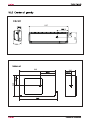
Order No.
Wall mounted Type
ON/OFF EK -Series
Model No.HSU24VHK-G&W
WARNING
This service information is designed for experienced repair technicians only and is not designed for use by the general public.
It does not contain warnings or cautions to advise non-technical individuals of potential dangers in attempting to service a product.
Products powered by electricity should be serviced or repaired only by experienced professional technicians. Any attempt to service or
repair the product or products dealt with in this service information by anyone else could result in serious injury or death
©2012(Qingdao Haier Air Conditioner General corp.,Ltd)
All right reserved .Unauthorized copying and distribution is a violation of law
Haier Group
Table of Contents
1.Features...................................................................................................... 1
2.Introduction ................................................................................................ 2
3.Specifications ............................................................................................. 7
4.Printed circuit board connector wiring diagram ..................................... 9
5.Functions and control .............................................................................. 10
5.1 Main functions and control specification .................................................. 10
5.2 Value of thermistor ................................................................................... 15
6. System configuration ............................................................................... 23
6.1 System configuration ................................................................................ 23
6.2 Instruction ................................................................................................. 24
7. Service diagnosis .................................................................................... 31
7.1 Caution for diagnosis ................................................................................ 31
7.2 Problem symptoms and measures ........................................................... 32
8. Capacity diagrams and curves diagrams ............................................... 34
9. Installations ............................................................................................... 39
10.Wiring Diagrams ....................................................................................... 43
Domestic Air Conditioner
Features
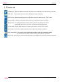
1. Features
Intelligent air With twin-blade technology ,the airflow can be adjusted not to blow directly to human
ESF filter : Trap harmful dust and remove unpleasant odors effectively
DRY function: Make dehumidifying in the room when the unit is working in the "DRY" mode
Anti-mold filter: Catches most small particles and remove unpleasant odors effectively
Sleep mode: The setting temprature and the indoor noise can be adjusted to a more
comfortable level when you set the "sleep mode"during night sleep
24 Hour timer: Use the timer function to set on,or off,or from on to off,or from off to on
Auto restart: The function permits automatic return to previous peration conditions
Easy clean design: The panel is easy to wash and the airflow vents can be detached without
any special tools for quick cleaning of the inside of the air conditioner
Auto mode: According to the fixed temperature,the unit will adjust the operation mode automatically.
1
Domestic Air Conditioner
Introduction
2. Introduction
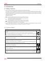
2.1 Safety Cautions
Be sure to read the following safety cautions before conducting repair work.
The caution items are classified into “Warning” and “Caution”. The “Warning” items are especially important
since they can lead to death or serious injury if they are not followed closely. The “Caution” items can also lead
to serious accidents under some conditions if they are not followed. Therefore, be sure to observe all the safety
caution items described below.
About the pictograms
This symbol indicates an item for which caution must be exercised.
The pictogram shows the item to which attention must be paid.
This symbol indicates a prohibited action.
The prohibited item or action is shown inside or near the symbol.
This symbol indicates an action that must be taken, or an instruction.
The instruction is shown inside or near the symbol.
After the repair work is complete, be sure to conduct a test operation to ensure that the equipment operates
normally, and explain the cautions for operating the product to the customer.
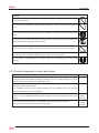
2.1.1 Caution in Repair
Warning
Be sure to disconnect the power cable plug from the plug socket before disassembling the equipment for
a repair.
Working on the equipment that is connected to a power supply can cause an electrical shook.
If it is necessary to supply power to the equipment to conduct the repair or inspecting the circuits, do not
touch any electrically charged sections of the equipment.
If the refrigerant gas discharges during the repair work, do not touch the discharging refrigerant gas.The
refrigerant gas can cause frostbite.
When disconnecting the suction or discharge pipe of the compressor at the welded section, release the
refrigerant gas completely at a well-ventilated place first.
If there is a gas remaining inside the compressor, the refrigerant gas or refrigerating machine oil
discharges when the pipe is disconnected, and it can cause injury.
If the refrigerant gas leaks during the repair work, ventilate the area. The refrigerant gas can generate
toxic gases when it contacts flames.
The step-up capacitor supplies high-voltage electricity to the electrical components of the outdoor unit.
Be sure to discharge the capacitor completely before conducting repair work.A charged capacitor can
cause an electrical shock.
Do not start or stop the air conditioner operation by plugging or unplugging the power cable plug.
Plugging or unplugging the power cable plug to operate the equipment can cause an electrical shock or
fire.
2
Domestic Air Conditioner
Introduction
Warning
Do not repair the electrical components with wet hands. Working on the equipment with wet hands can
cause an electrical shock.
Do not clean the air conditioner by splashing water. Washing the unit with water can cause an electrical
shock.
Be sure to provide the grounding when repairing the equipment in a humid or wet place, to avoid electrical
shocks.
Be sure to turn off the power switch and unplug the power cable when cleaning the equipment. The
internal fan rotates at a high speed, and cause injury.
Do not tilt the unit when removing it. The water inside the unit can spill and wet the furniture and floor.
Be sure to check that the refrigerating cycle section has cooled down sufficiently before conducting repair
work. Working on the unit when the refrigerating cycle section is hot can cause burns.
Use the welder in a well-ventilated place. Using the welder in an enclosed room can cause oxygen
deficiency.
2.1.2 Cautions Regarding Products after Repair
Warning
Be sure to use parts listed in the service parts list of the applicable model and appropriate tools to
conduct repair work. Never attempt to modify the equipment. The use of inappropriate parts or tools can
cause an electrical shock, excessive heat generation or fire.
When relocating the equipment, make sure that the new installation site has sufficient strength to
withstand the weight of the equipment.
If the installation site does not have sufficient strength and if the installation work is not conducted
securely, the equipment can fall and cause injury.
Be sure to install the product correctly by using the provided standard installation frame.
For
Incorrect use of the installation frame and improper installation can cause the equipment to fall, resulting
in injury.
integral
units only
Be sure to install the product securely in the installation frame mounted on a window frame.
If the unit is not securely mounted, it can fall and cause injury.
3
For
integral
units only
Domestic Air Conditioner
Introduction
Warning
Be sure to use an exclusive power circuit for the equipment, and follow the technical standards related to
the electrical equipment, the internal wiring regulations and the instruction manual for installation when
conducting electrical work.
Insufficient power circuit capacity and improper electrical work can cause an electrical shock or fire.
Be sure to use the specified cable to connect between the indoor and outdoor units. Make the
connections securely and route the cable properly so that there is no force pulling the cable at the
connection terminals.
Improper connections can cause excessive heat generation or fire.
When connecting the cable between the indoor and outdoor units, make sure that the terminal cover does
not lift off or dismount because of the cable.
If the cover is not mounted properly, the terminal connection section can cause an electrical shock,
excessive heat generation or fire.
Do not damage or modify the power cable.
Damaged or modified power cable can cause an electrical shock or fire. Placing heavy items on the
power cable, and heating or pulling the power cable can damage the cable.
Do not mix air or gas other than the specified refrigerant (R-410A / R22) in the refrigerant system.
If air enters the refrigerating system, an excessively high pressure results, causing equipment damage
and injury.
If the refrigerant gas leaks, be sure to locate the leak and repair it before charging the refrigerant. After
charging refrigerant, make sure that there is no refrigerant leak.
If the leak cannot be located and the repair work must be stopped, be sure to perform pump-down and
close the service valve, to prevent the refrigerant gas from leaking into the room. The refrigerant gas itself
is harmless, but it can generate toxic gases when it contacts flames, such as fan and other heaters,
stoves and ranges.
When replacing the coin battery in the remote controller, be sure to disposed of the old battery to prevent
children from swallowing it.
If a child swallows the coin battery, see a doctor immediately.
Caution
Installation of a leakage breaker is necessary in some cases depending on the conditions of the
installation site, to prevent electrical shocks.
Do not install the equipment in a place where there is a possibility of combustible gas leaks.
If a combustible gas leaks and remains around the unit, it can cause a fire.
Be sure to install the packing and seal on the installation frame properly. If the packing and seal are not
installed properly, water can enter the room and wet the furniture and floor.
4
For
integral
units only
Domestic Air Conditioner
Introduction
Warning
Do not repair the electrical components with wet hands. Working on the equipment with wet hands can
cause an electrical shock.
Do not clean the air conditioner by splashing water. Washing the unit with water can cause an electrical
shock.
Be sure to provide the grounding when repairing the equipment in a humid or wet place, to avoid electrical
shocks.
Be sure to turn off the power switch and unplug the power cable when cleaning the equipment. The
internal fan rotates at a high speed, and cause injury.
Do not tilt the unit when removing it. The water inside the unit can spill and wet the furniture and floor.
Be sure to check that the refrigerating cycle section has cooled down sufficiently before conducting repair
work. Working on the unit when the refrigerating cycle section is hot can cause burns.
Use the welder in a well-ventilated place. Using the welder in an enclosed room can cause oxygen
deficiency.
2.1.3 Cautions Regarding Products after Repair
Warning
Be sure to use parts listed in the service parts list of the applicable model and appropriate tools to
conduct repair work. Never attempt to modify the equipment. The use of inappropriate parts or tools can
cause an electrical shock, excessive heat generation or fire.
When relocating the equipment, make sure that the new installation site has sufficient strength to
withstand the weight of the equipment.
If the installation site does not have sufficient strength and if the installation work is not conducted
securely, the equipment can fall and cause injury.
Be sure to install the product correctly by using the provided standard installation frame.
For
Incorrect use of the installation frame and improper installation can cause the equipment to fall, resulting
in injury.
integral
units only
Be sure to install the product securely in the installation frame mounted on a window frame.
If the unit is not securely mounted, it can fall and cause injury.
5
For
integral
units only
Domestic Air Conditioner
Introduction
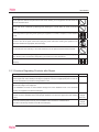
2.1.4 Using Icons
Icons are used to attract the attention of the reader to specific information. The meaning of each icon is described in
the table below:
2.1.5 Using Icons List
Icon
Type of Information
Description
A “note” provides information that is not indispensable, but may
Note:
Note
Caution
Caution
nevertheless be valuable to the reader, such as tips and tricks.
A “caution” is used when there is danger that the reader, through
incorrect manipulation, may damage equipment, loose data, get an
unexpected result or has to restart (part of) a procedure.
Warning
Warning
A “warning” is used when there is danger of personal injury.
A “reference” guides the reader to other places in this binder or in
Reference
this manual, where he/she will find additional information on a
specific topic.
6
Domestic Air Conditioner
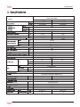
Specifications
HSU24VHK-G&W
Model
Heating
Cooling
6270/6450
6270/6450
21400/22000
21400/22000
PH
HZ
60
V
208/230V
PINT/h
EER/COP
4.6
--
9.6/8.9
9.6/8.9
2010/1960
2010/1960
10.94
BTU/(H*W)
10.94
IN
0.375
IN
0.625
IN
0.63
Both Liquid and Gas Pipes
IN
787
IN
197
IN
197
1bs/in
1.12
Indoor Unit
HSU24VHK-G
White
CFM
765
765
--
--
--
--
Cross Flow Fan
40
3 Steps, Silent, Auto
Horizontal, Downward
Removable / Washable / Mildew Proof
0.04
0.04
15
15
Microcomputer Control
(WxHxD)
(WxHxD)
IN
45.16x12.6x10.28
IN
48.54x15.28x14.33
1bs
36.38
1bs
42.99
49 / 46 / 43
58
7
49/ 46 / 43
58
Domestic Air Conditioner
Specifications
Outdoor Unit
HSU24VHK-W
White
Rotary Compressor
ASH218RN
1805/1815
ESTER OIL VG74
0.6
R410A
2.45
19.6
568.3
Axial fan
65
7.45
1805
IN
37.32x13.39x33.07
IN
42.91x16.14x36.81
1bs
136.69
1bs
145.50
58
58
Conversion Formulate
Heating
Indoor:95 0 FDB/71 0 FDB
Indoor:73 0 FDB
3413
196.85 IN
Outdoor:121 0 FDB/850FDB Outdoor:31 0 FDB/28 0 FDB
8
Domesfication Air Conditioner
Connector W r i Wing Diagram
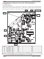
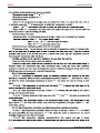
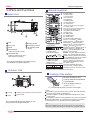
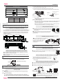
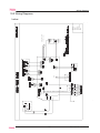
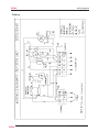
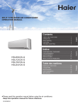
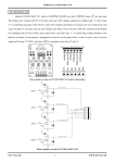
4.Printed Circuit Board Connector Wiring Diagram
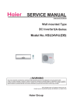
4.1 Indoor unit
Connectors Indoor PCB
1)CN1connector for transformer input
3)CN3 connector for transformer output
2)CN2 connector for terminal block
4)CN5” or CN5”(1) connector for up and down step motor 5)CN6 connector for ambient temp. sensor and piping temp
6)CN7 connector for receiver display 7)CN8 connector for AC fan feedback motor 8)CN9 connector for AC fan motor
CN8
CN7
.
CN5” /CN5”(1)
CN9
CN6
CN1
CN2
&1
Domest i c Air Condit i oner
Functions and Control
5
Functions and control
5.1 main functions and control specifications
Including brief introduction to air conditioners of series models and electric control function.
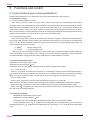
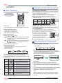
5.1.1 Automatic running
5.1.1.1 Single cold automatic run mode:
After entering into this mode, the main control “MCU” determines the corresponding work pattern
according to the indoor temperature so as to maintain the preset temperature (the preset temperature is 92 0F).
When the indoor temperature is below 92 0F , outlet air from compressor is off, the automatic wind from fan
motor is low, and wind can be set to high, medium or low by hand. When the indoor temperature is or above
92 0F , the unit enters the cooling mode and conducts the cooling programme (the preset temperature is 92 0F),
outlet air from compressor is on and indoor fan motor run in fixed wind speed.
5.1.1.2 Automatic running mode
When the running mode is turned to automation after starting the system, the system will first determine
the running mode according to the current room temperature and then will run according to the determined
mode. Tr in the following selection conditions means room temperature, Ts means setting temperature, Tp
means temperature of indoor coil pipe
a. Tr 83 0F
running cooling mode
b. Tr< 83 0F
running heating mode
After turning to the automation mode, the running mode can be switched between cooling mode, fan
mode and heating mode according to the change of the indoor ambient temperature. But the automatic
conversion between cooling mode and heating mode must be conducted after 15 minutes.
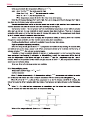
5.1.2 Indoor temperature control
Temperature control range : 60 0F—105 0F
Temperature control precision: 12 0F
Compressor can’t be controlled by temperature sensor within 2 minutes after it starts
5.1.2.1 Cooling mode:
When Tr> Ts, outdoor fan motor and compressor on, and indoor fan motor run at fixed wind speed. When Tr
Ts, outdoor fan motor and compressor off, and when Tr > Ts, outdoor fan motor and compressor are working
again .If Tr=Ts, the indoor fan motor , outdoor fan motor and the compressor’s state will not change.
5.1.2.2 Heating mode:
When Tr
Ts, compressor, four-ways valve and outdoor fan motor is on, indoor fan
motor runs as in cold blast avoidance mode, and 4 of compensation is added after compressor is started.
When Tr>Ts+5 , compressor is off, and the indoor fan motor runs as in cold blast avoidance mode.
When Tr<Ts+5 , compressor, four-ways valve and outdoor fan motor is on, and the indoor fan motor runs
as in the mode of avoiding cold blast.
5.1.3 Cooling run mode:
temperature control range : 60 0F—105 0F
temperature control precision: 12 0F
compressor can’t be controlled by temperature sensor within 2 minutes after it starts.
control character: when Tr Ts, outlet air from compressor is on and indoor fan motor run at fixed
wind speed. When Tr Ts, outlet air from compressor is off , and when Tr > Ts, outlet air from compressor
is on.
10
Domestic Air Conditioner
Functions and Control
12 0F
19 0F
19 0F
12 0F
207 0 F
2010F
9 0F
31 0F
60 0F
105 0F
15 0F
15 0F
12 0F
Domestic Air Conditioner
Functions and Control
105 0F
60 0F
12 0F
22 0F
25 0F
25 0F
15 0F
15 0F
83 0F
83 0F
131 0F
131 0F
131 0F
131 0F
83 0F
73 0F
188 0F
175 0F
12
Domestic Air Conditioner
Function and Control
169 0F
22 0F
131 0 F
131 0F
9 0F
131 0F
60 0F
131 0F
13
Domestic Air Conditioner
Functions and Control
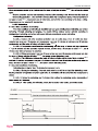
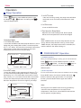
5.1.6 Timer function:
You can set 24-hour timer on or timer off as required, and the minum time unit is 1 minute. After
setting, the indicator of indoor unit is on , and it is off when timer setting is completed. There are several
timer mode as follows.
5.1.6.1 Timer on: The LED of “timer on” lights up, and unit behaves with halt status. Timer on is
completed, and then unit starts running with the LED of “timer on” off. The unit starts with the the last
setting receiving timer signals, and sleep setting is not allowed.
5.1.6.2 Timer off: Unit starts, timer indicator lights up; When reaching time setting, the indicator
goes out, unit enters shut down mode, and sleep function can be set. If timer off and sleep are set
synchronously, the one which time is short run first. Executing shutdown instruction clear timer and sleep
function.
5.1.6.3 Timer on and timer off can be set synchronously.
5.1.7 Sleep function: the timer indicator lights up.
5.1.7.1 In cooling/defrosting mode, the temp. setting increases 120F one hour later after start up.
After another hour the temp. setting increase by more 120F and then run continuously for another 6 hours
and then close.
5.1.7.2 In heating mode, the temp. setting decrease 15 0F one hour after start up. After another
hour the temp. setting decrease by more 15 0F. After 3 hours the temp. setting rise by 12 0F and then run
continuously for another 3 hours and then close.
5.1.7.3 If the wind speed is set to high before going to bed, the wind speed become medium after
start up; If the wind speed is set to medium before going to bed, the wind speed become low after start
up; If the wind speed is set to low before going to bed, the wind speed keep unchanged.
5.1.8 Emergency switch imput:
5.1.8.1 Press the switch of emergency operation, then buzzer rings once and unit enters the
automatic operation mode. (emergency operation)
5.1.8.2 If the switch is kept pressed for 5 seconds, buzzer ring two times and unit enter enter test
run mode.
5.1.8.3 Press the switch again, and then closes.
14
Domestic Air Conditioner
Functions and Control
5.1.8.4 Enter emergency operation from timer mode, then timer is cancelled.
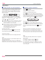
5.1.9 Test run:
5.1.9.1 The temperature sensor of inlet air doesn’t work, and compressor starts (but subject to the
limit of -minute delay excluding the first time), and high wind, cooling, and air door is open.The indoor fan
motor runs, running indicator lights up, compressor relay and the one of outdoor fan motor is closed
5.1.9.2 During test run:
The prevention of freezing of evaporator doesn’t work.
Current cross control doesn’t work.
The control of current cross peak expiration doesn’t work.
Temperature control doesn’t work.
Temperature expiration control doesn’t work.
5.1.10 memory function The memory function of power down is available, and the auto recovery
function of power on is optional. (In auto, heating, cooling, or defrosting status, press the “sleeping”
button 10 times within 5 seconds, and the auto recovery function of power on can be set on/off. If the
buzzer rings 4 times, the the auto recovery function of power on is available; If the buzzer rings 2 times,
the the auto recovery function of power on is unavailable.)
If there is no EEPROM, the unit is taken off the ‘off’ function of the memory function of power down.
But the memory function of power down can also be set on/off, and the data is the default value of chip.
5.1.11 Alarm from indoor fan motor: 2 minutes later after the indoor fan motor is charged, and the
impulse from fan motor is not detected, hen send alarm signals.
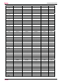
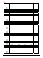
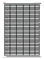
5.2 Value of Thermistor
5.2.1 Indoor unit
Room sensor
R89 F=23K ±3.5%
B89 0F/169 0F=4200K±3%
0
Temp.(0F)
Tolerance( 0F)
Max.(K )
Normal(K )
Min.(K )
-22.0
568.8372
501.0746
440.8435
-3.55
3.15
-20.2
530.9600
468.6491
413.1441
-3.51
3.13
-18.4
495.8488
438.5314
387.3645
-3.47
3.10
-16.6
463.2850
410.5433
363.3602
-3.44
3.08
-14.8
433.0683
384.5212
340.9980
-3.42
3.06
-13.0
405.0156
360.3153
320.1558
-3.38
3.04
-11.2
378.9588
337.7879
300.7211
-3.35
3.01
-9.4
354.7440
316.8126
282.5905
-3.31
2.99
-7.6
332.2300
297.2732
265.6686
-3.28
2.95
-5.8
311.2873
279.0627
249.8676
-3.24
2.93
-4.0
291.7969
262.0831
235.1067
-3.20
2.92
-2.2
273.6494
246.2437
221.3111
-3.17
2.88
-0.4
256.7445
231.4612
208.4122
-3.13
2.86
1.4
240.9897
217.6590
196.3462
-3.10
2.83
3.2
226.3000
204.7662
185.0545
-3.06
2.81
5.0
212.5973
192.7176
174.4829
-3.02
2.77
15
Domestic Air Conditioner
Functions and Control
6.8
199.8093
181.4531
164.5813
-2.99
2.75
8.6
187.8698
170.9169
155.3033
-2.95
2.72
10.4
176.7176
161.0578
146.6059
-2.92
2.68
12.2
166.2961
151.8284
138.4495
-2.88
2.66
14.0
156.5532
143.1847
130.7973
-2.84
2.63
15.8
147.4409
135.0863
123.6153
-2.81
2.59
17.6
138.9148
127.4956
116.8717
-2.75
2.57
19.4
130.9337
120.3778
110.5374
-2.72
2.54
21.2
123.4597
113.7009
104.5852
-2.68
2.50
23.0
116.4577
107.4349
98.9897
-2.65
2.48
24.8
109.8953
101.5523
93.7278
-2.61
2.45
26.6
103.7422
96.0274
88.7774
-2.57
2.41
28.4
97.9708
90.8365
84.1185
-2.52
2.38
30.2
92.5551
85.9574
79.7322
-2.48
2.34
32.0
87.4712
81.3697
75.6011
-2.45
2.32
33.8
82.6970
77.0544
71.7088
-2.41
2.29
35.6
78.2118
72.9937
68.0402
-2.36
2.25
37.4
73.9966
69.1712
64.5813
-2.32
2.21
39.2
70.0335
65.5716
61.3188
-2.29
2.18
41.0
66.3062
62.1807
58.2405
-2.23
2.14
42.8
62.7992
58.9853
55.3351
-2.20
2.11
44.6
59.4984
55.9729
52.5917
-2.16
2.07
46.4
56.3905
53.1320
50.0006
-2.11
2.03
48.2
53.4631
50.4521
47.5523
-2.07
2.00
50.0
50.7048
47.9230
45.2384
-2.03
1.96
51.8
48.1049
45.5355
43.0505
-1.98
1.93
53.6
45.6534
43.2808
40.9813
-1.94
1.87
55.4
43.3410
41.1509
39.0236
-1.89
1.84
57.2
41.1592
39.1381
37.1708
-1.85
1.80
59.0
39.0998
37.2355
35.4167
-1.80
1.76
60.8
37.1553
35.4363
33.7555
-1.76
1.73
62.6
35.3186
33.7344
32.1818
-1.71
1.69
64.4
33.5833
32.1240
30.6905
-1.67
1.64
66.2
31.9432
30.5997
29.2769
-1.62
1.60
68.0
30.3925
29.1565
27.9365
-1.58
1.57
69.8
28.9259
27.7895
26.6651
-1.53
1.51
71.6
27.5383
26.4944
25.4589
-1.49
1.48
73.4
26.2252
25.2670
24.3140
-1.44
1.44
75.2
24.9822
24.1034
23.2271
-1.40
1.39
77.0
23.8050
23.0000
22.1950
-1.40
1.39
78.8
22.7500
21.9499
21.1520
-1.40
1.40
80.6
21.7477
20.9536
20.1638
-1.48
1.46
82.4
20.7951
20.0081
19.2272
-1.55
1.53
84.2
19.8895
19.1104
18.3394
-1.60
1.58
86.0
19.0285
18.2581
17.4974
-1.67
1.66
16
Domestic Air Conditioner
Functions and Control
87.8
18.2094
17.4484
16.6988
-1.75
1.71
89.6
17.4302
16.6792
15.9410
-1.80
1.78
91.4
16.6885
15.9480
15.2217
-1.87
1.84
93.2
15.9825
15.2530
14.5389
-1.94
1.91
95.0
15.3103
14.5920
13.8903
-2.02
1.96
96.8
14.6700
13.9632
13.2743
-2.09
2.03
98.6
14.0599
13.3650
12.6889
-2.16
2.09
100.4
13.4786
12.7957
12.1325
-2.21
2.16
102.2
12.9244
12.2537
11.6035
-2.29
2.23
104.0
12.3960
11.7375
11.1004
-2.36
2.29
105.8
11.8921
11.2459
10.6218
-2.43
2.36
107.6
11.4113
10.7775
10.1665
-2.50
2.41
109.4
10.9526
10.3311
9.7330
-2.57
2.48
111.2
10.5147
9.9056
9.3204
-2.66
2.56
113.0
10.0967
9.4999
8.9275
-2.74
2.61
114.8
9.6976
9.1130
8.5532
-2.81
2.68
116.6
9.3163
8.7439
8.1965
-2.88
2.75
118.4
8.9521
8.3916
7.8566
-2.95
2.83
120.2
8.6040
8.0554
7.5327
-3.02
2.88
122.0
8.2713
7.7345
7.2237
-3.11
2.95
123.8
7.9531
7.4280
6.9291
-3.19
3.02
125.6
7.6489
7.1353
6.6480
-3.26
3.10
127.4
7.3580
6.8556
6.3797
-3.33
3.17
129.2
7.0796
6.5884
6.1237
-3.42
3.22
131.0
6.8131
6.3329
5.8793
-3.49
3.29
132.8
6.5581
6.0887
5.6459
-3.58
3.37
134.6
6.3140
5.8552
5.4230
-3.65
3.44
136.4
6.0802
5.6318
5.2100
-3.73
3.51
138.2
5.8563
5.4181
5.0065
-3.82
3.58
140.0
5.6417
5.2136
4.8120
-3.89
3.65
141.8
5.4361
5.0178
4.6260
-3.98
3.73
143.6
5.2391
4.8304
4.4481
-4.05
3.80
145.4
5.0502
4.6510
4.2780
-4.14
3.87
147.2
4.8691
4.4791
4.1153
-4.23
3.94
149.0
4.6954
4.3145
3.9596
-4.30
4.01
150.8
4.5287
4.1567
3.8105
-4.39
4.09
152.6
4.3689
4.0055
3.6678
-4.48
4.16
154.4
4.2154
3.8605
3.5312
-4.55
4.23
156.2
4.0682
3.7216
3.4004
-4.64
4.30
158.0
3.9268
3.5883
3.2750
-4.73
4.37
159.8
3.7910
3.4605
3.1549
-4.82
4.46
161.6
3.6606
3.3378
3.0398
-4.91
4.54
163.4
3.5353
3.2201
2.9294
-4.99
4.61
165.2
3.4150
3.1072
2.8237
-5.08
4.68
167.0
3.2993
2.9987
2.7222
-5.17
4.75
17
Domestic Air Conditioner
Functions and Control
168.8
3.1881
2.8946
2.6249
-5.26
4.82
170.6
3.0812
2.7946
2.5316
-5.35
4.91
172.4
2.9785
2.6986
2.4420
-5.44
4.99
174.2
2.8796
2.6063
2.3560
-5.53
5.06
176.0
2.7845
2.5176
2.2735
-5.62
5.15
178.8
2.6931
2.4324
2.1943
-5.71
5.22
179.6
2.6050
2.3505
2.1182
-5.80
5.29
181.4
2.5203
2.2717
2.0451
-5.90
5.38
183.2
2.4388
2.1960
1.9749
-5.99
5.45
185.0
2.3602
2.1231
1.9075
-6.08
5.53
186.8
2.2846
2.0530
1.8426
-6.17
5.62
188.6
2.2118
1.9856
1.7803
-6.26
5.69
190.4
2.1416
1.9207
1.7204
-6.37
5.76
192.2
2.0740
1.8582
1.6628
-6.46
5.85
194.0
2.0089
1.7981
1.6074
-6.55
5.92
195.8
1.9461
1.7402
1.5541
-6.66
6.01
197.6
1.8856
1.6844
1.5028
-6.75
6.08
199.4
1.8272
1.6307
1.4535
-6.84
6.17
201.2
1.7709
1.5789
1.4060
-6.95
6.25
203.0
1.7166
1.5291
1.3603
-7.04
6.34
204.8
1.6643
1.4810
1.3163
-7.15
6.41
206.6
1.6138
1.4347
1.2739
-7.24
6.50
208.4
1.5650
1.3900
1.2331
-7.34
6.59
210.2
1.5180
1.3470
1.1937
-7.43
6.66
212.0
1.4726
1.3054
1.1559
-7.54
6.75
213.8
1.4287
1.2654
1.1194
-7.63
6.84
215.6
1.3864
1.2268
1.0842
-7.74
6.91
217.4
1.3455
1.1895
1.0503
-7.85
7.00
219.2
1.3060
1.1535
1.0176
-7.96
7.09
221.0
1.2679
1.1188
0.9860
-8.05
7.16
222.8
1.2310
1.0853
0.9556
-8.15
7.25
224.6
1.1954
1.0529
0.9263
-8.26
7.34
226.4
1.1610
1.0217
0.8980
-8.37
7.43
228.2
1.1277
0.9915
0.8707
-8.46
7.51
230.0
1.0955
0.9624
0.8443
-8.57
7.60
231.8
1.0644
0.9342
0.8189
-8.68
7.69
233.6
1.0344
0.9070
0.7943
-8.78
7.78
235.4
1.0053
0.8807
0.7706
-8.89
7.87
237.2
0.9771
0.8553
0.7478
-9.00
7.94
239.0
0.9499
0.8307
0.7256
-9.11
8.03
240.8
0.9235
0.8070
0.7043
-9.22
8.12
242.6
0.8980
0.7840
0.6837
-9.32
8.21
244.4
0.8734
0.7618
0.6637
-9.43
8.30
246.2
0.8495
0.7404
0.6445
-9.54
8.39
248.0
0.8263
0.7196
0.6258
-9.65
8.48
18
Domestic Air Conditioner
Functions and Control
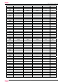
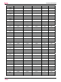
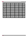
Pipe Sensor
R89 0F =10K ±3%
B89 0F/169 0F=3700K±3%
0
Tolerance( 0F )
Max.(K )
Normal(K )
Min.(K )
-22..0
165.2170
147.9497
132.3678
-3.49
3.15
-20.2
155.5754
139.5600
125.0806
-3.47
3.13
-18.4
146.5609
131.7022
118.2434
-3.44
3.11
-16.6
138.1285
124.3392
111.8256
-3.40
3.08
-14.8
130.2371
117.4366
105.7989
-3.37
3.06
-13.0
122.8484
110.9627
100.1367
-3.33
3.04
-11.2
115.9272
104.8882
94.8149
-3.29
3.01
-9.4
109.4410
99.1858
89.8106
-3.26
2.99
-7.6
103.3598
93.8305
85.1031
-3.24
2.95
-5.8
97.6556
88.7989
80.6728
-3.20
2.93
-4.0
92.3028
84.0695
76.5017
-3.17
2.92
-2.2
87.2775
79.6222
72.5729
-3.13
2.88
-0.4
82.5577
75.4384
68.8710
-3.12
2.86
1.4
78.1230
71.5010
65.3815
-3.06
2.83
3.2
73.9543
67.7939
62.0907
-3.02
2.79
5.0
70.0342
64.3023
58.9863
-2.99
2.77
6.8
66.3463
61.0123
56.0565
-2.95
2.74
8.6
62.8755
57.9110
53.2905
-2.92
2.72
10.4
59.6076
54.9866
50.6781
-2.88
2.68
12.2
56.5296
52.2278
48.2099
-2.84
2.65
14.0
53.6294
49.6244
45.8771
-2.81
2.63
15.8
50.8956
47.1666
43.6714
-2.77
2.59
17.6
48.3178
44.8454
41.5851
-2.72
2.56
19.4
45.8860
42.6525
39.6112
-2.68
2.52
21.2
43.5912
40.5800
37.7429
-2.65
2.50
23.0
41.4249
38.6207
35.9739
-2.61
2.47
24.8
39.3792
36.7676
34.2983
-2.57
2.43
26.6
37.4465
35.0144
32.7108
-2.54
2.39
28.4
35.6202
33.3552
31.2062
-2.48
2.36
30.2
33.8936
31.7844
29.7796
-2.45
2.32
32.0
32.2608
30.2968
28.4267
-2.41
2.30
33.8
30.7162
28.8875
27.1431
-2.38
2.27
35.6
29.2545
27.5519
25.9250
-2.32
2.23
37.4
27.8708
26.2858
24.7686
-2.29
2.20
39.2
26.5605
25.0851
23.6704
-2.25
2.16
41.0
25.3193
23.9462
22.6273
-2.21
2.12
42.8
24.1432
22.8656
21.6361
-2.16
2.09
44.6
23.0284
21.8398
20.6939
-2.12
2.05
46.4
21.9714
20.8659
19.7982
-2.07
2.02
48.2
20.9688
19.9409
18.9463
-2.03
1.96
Temp.
F
19
Domestic Air Conditioner
Functions and Control
50.0
20.0176
19.0621
18.1358
-2.00
1.93
51.8
19.1149
18.2270
17.3646
-1.94
1.89
53.6
18.2580
17.4331
16.6305
-1.91
1.85
55.4
17.4442
16.6782
15.9315
-1.85
1.82
57.2
16.6711
15.9601
15.2657
-1.82
1.78
59.0
15.9366
15.2770
14.6315
-1.76
1.73
60.8
15.2385
14.6268
14.0271
-1.73
1.69
62.4
14.5748
14.0079
13.4510
-1.67
1.66
64.6
13.9436
13.4185
12.9017
-1.64
1.62
66.2
13.3431
12.8572
12.3778
-1.58
1.57
68.0
12.7718
12.3223
11.8780
-1.55
1.53
69.8
12.2280
11.8126
11.4011
-1.49
1.49
71.6
11.7102
11.3267
10.9459
-1.46
1.44
73.4
11.2172
10.8634
10.5114
-1.40
1.40
75.2
10.7475
10.4216
10.0964
-1.35
1.35
77.0
10.3000
10.0000
9.7000
-1.35
1.35
78.8
9.8975
9.5974
9.2980
-1.37
1.37
80.6
9.5129
9.2132
8.9148
-1.44
1.44
82.4
9.1454
8.8465
8.5496
-1.51
1.49
84.2
8.7942
8.4964
8.2013
-1.57
1.55
86.0
8.4583
8.1621
7.8691
-1.64
1.62
87.8
8.1371
7.8428
7.5522
-1.71
1.67
89.6
7.8299
7.5377
7.2498
-1.76
1.75
91.4
7.5359
7.2461
6.9611
-1.84
1.80
93.2
7.2546
6.9673
6.6854
-1.91
1.87
95.0
6.9852
6.7008
6.4222
-1.98
1.93
96.8
6.7273
6.4459
6.1707
-2.03
2.00
98.6
6.4803
6.2021
5.9304
-2.11
2.05
100.4
6.2437
5.9687
5.7007
-2.18
2.12
102.2
6.0170
5.7454
5.4812
-2.25
2.20
104.0
5.7997
5.5316
5.2712
-2.32
2.25
105.8
5.5914
5.3269
5.0704
-2.39
2.32
107.6
5.3916
5.1308
4.8783
-2.47
2.39
109.4
5.2001
4.9430
4.6944
-2.54
2.45
111.2
5.0163
4.7630
4.5185
-2.61
2.52
113.0
4.8400
4.5905
4.3500
-2.68
2.59
114.8
4.6708
4.4252
4.1887
-2.75
2.65
116.6
4.5083
4.2666
4.0342
-2.83
2.72
118.4
4.3524
4.1145
3.8862
-2.90
2.79
120.2
4.2026
3.9686
3.7443
-2.97
2.86
122.0
4.0588
3.8287
3.6084
-3.06
2.92
3.9206
3.6943
3.4780
-3.13
2.99
125.6
3.7878
3.5654
3.3531
-3.20
3.06
127.4
3.6601
3.4416
3.2332
-3.28
3.13
129.2
3.5374
3.3227
3.1183
-3.37
3.20
123.8
20
Domestic Air Conditioner
Functions and Control
131.0
3.4195
3.2085
3.0079
-3.44
3.28
132.8
3.3060
3.0989
2.9021
-3.51
3.33
134.6
3.1969
2.9935
2.8005
-3.60
3.40
136.4
3.0919
2.8922
2.7029
-3.67
3.47
138.2
2.9909
2.7948
2.6092
-3.74
3.55
140.0
2.8936
2.7012
2.5193
-3.83
3.62
141.8
2.8000
2.6112
2.4328
-3.91
3.69
143.6
2.7099
2.5246
2.3498
-4.00
3.76
145.4
2.6232
2.4413
2.2700
-4.07
3.83
147.2
2.5396
2.3611
2.1932
-4.16
3.91
149.0
2.4591
2.2840
2.1195
-4.25
3.98
150.8
2.3815
2.2098
2.0486
-4.32
4.05
152.6
2.3068
2.1383
1.9803
-4.41
4.12
154.4
2.2347
2.0695
1.9147
-4.48
4.21
156.2
2.1652
2.0032
1.8516
-4.57
4.28
158.0
2.0983
1.9393
1.7908
-4.66
4.36
159.8
2.0337
1.8778
1.7324
-4.73
4.43
161.6
1.9714
1.8186
1.6761
-4.82
4.50
163.4
1.9113
1.7614
1.6219
-4.91
4.57
165.2
1.8533
1.7064
1.5697
-5.00
4.84
167.0
1.7974
1.6533
1.5194
-5.09
4.73
168.8
1.7434
1.6021
1.4710
-5.18
4.81
170.6
1.6913
1.5528
1.4243
-5.26
4.88
172.4
1.6409
1.5051
1.3794
-5.35
4.95
174.2
1.5923
1.4592
1.3360
-5.44
5.04
176.0
1.5454
1.4149
1.2942
-5.53
5.11
177.8
1.5000
1.3721
1.2540
-5.62
5.18
179.6
1.4562
1.3308
1.2151
-5.71
5.27
181.4
1.4139
1.2910
1.1776
-5.80
5.35
183.2
1.3730
1.2525
1.1415
-5.89
5.42
185.0
1.3335
1.2153
1.1066
-5.98
5.51
186.8
1.2953
1.1794
1.0730
-6.08
5.58
198.6
1.2583
1.1448
1.0405
-6.17
5.67
190.4
1.2226
1.1113
1.0092
-6.26
5.74
192.2
1.1880
1.0789
0.9789
-6.35
5.83
194.0
1.1546
1.0476
0.9497
-6.44
5.90
195.8
1.1223
1.0174
0.9215
-6.55
5.99
197.6
1.0910
0.9882
0.8942
-6.64
6.07
199.4
1.0607
0.9599
0.8679
-6.73
6.16
201.2
1.0314
0.9326
0.8424
-6.84
6.23
203.0
1.0030
0.9061
0.8179
-6.93
6.32
204.8
0.9756
0.8806
0.7941
-7.02
6.39
206.6
0.9490
0.8558
0.7711
-7.13
6.48
208.4
0.9232
0.8319
0.7489
-7.22
6.55
210.2
0.8983
0.8088
0.7275
-7.33
6.64
21
Domestic Air Conditioner
Functions and Control
212.0
0.8741
0.7863
0.7067
-7.42
6.73
213.8
0.8507
0.7646
0.6867
-7.52
6.80
215.6
0.8281
0.7436
0.6672
-7.61
6.89
217.4
0.8061
0.7233
0.6484
-7.72
6.98
219.2
0.7848
0.7036
0.6303
-7.81
7.06
221.0
0.7641
0.6845
0.6127
-7.92
7.15
222.8
0.7441
0.6661
0.5957
-8.03
7.24
224.6
0.7247
0.6482
0.5792
-8.12
7.33
226.4
0.7059
0.6308
0.5632
-8.23
7.42
228.2
0.6877
0.6140
0.5478
-8.33
7.49
230.0
0.6700
0.5977
0.5328
-8.44
7.58
231.8
0.6528
0.5820
0.5183
-8.53
7.67
233.6
0.6361
0.5667
0.5043
-8.64
7.76
235.4
0.6200
0.5518
0.4907
-8.75
7.85
237.2
0.6043
0.5374
0.4775
-8.86
7.94
239.0
0.5891
0.5235
0.4648
-8.96
8.01
240.8
0.5743
0.5100
0.4524
-9.07
8.10
242.6
0.5600
0.4968
0.4404
-9.18
8.19
244.4
0.5460
0.4841
0.4288
-9.29
8.28
246.2
0.5325
0.4717
0.4175
-9.40
8.37
248.0
0.5194
0.4597
0.4066
-9.50
8.46
22
Domestic Air Conditioner
System Configuration
6. System Configuration
6.1 System Configuration
After the installation and test operation of the room air conditioner have been completed, it should be operated and
handled as described below. Every user would like to know the correct method of operation of the room air
conditioner, to check if it is capable of cooling (or heating) well, and to know a clever method of using it.In order to
meet this expectation of the users, giving sufficient explanations taking enough time can be said to reduce about
80% of the requests for servicing. However good the installation work is and however good the functions are, the
customer may blame either the room air conditioner or its installation work because of improper handling. The
installation work and handing over of the unit can only be considered to have been completed when its handling has
been explained to the user without using technical terms but giving full knowledge of the equipment.
23
Domestic Air Conditioner
System Configuration
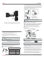
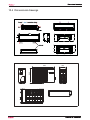
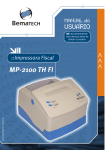
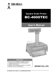
6.2Parts and Functions
Remote controller
Indoor Unit
1
6
2
7
3
8
1
4
5
8
9
2
18
10
Used to lock buttons and LCD display.
17. LIGHT button
19
11
20
3
9. QUIET button
10. HEAT button
11. COOL button
12. AUTO button
13. FAN button
14. TIMER button
15. HEALTH button
16. LOCK button
Control the lightening and extinguishing
of the indoor LED display board.
18. POWER ON/OFF button
19. DRY button
13
20. TEMP button
22
21. SWING button
14
22.
HOUR button
23
15
23. EXTRA FUNCTION button
24
Function˖Fan Mode— Healthy
16
airflow
upwarder — Healthy airflow
25
17
downwarder— Reset the healthy
airflow position — Right & left airflow
1. Mode display
setting— A-B yard— 50̧ low
Operation mode AUTO COOL DRY HEAT FAN
temperature heating— Sleep Mode—
Remote controller
Electrical Heating— Refresh Air—
2. Signal sending display
Power — Fahrenheit/Celsius mode
3. SWING display
shift on unit and remote
Remark˖A-B yard, Right & left airflow
4. FAN SPEED display
Display
setting, 50̧ low temperature heating,
circulated
Electrical Heating, Refresh Air functions
AUTO
LO
MED
HI
are not available for this mini split series.
5. LOCK display
24.CANCEL/CONFIRM button
6. TIMER OFF display
Function: Setting and cancel to the
TIMER ON display
timer and other additional functions.
7.TEMP display
25. RESET button
8.Additional functions display
If the remote appears abnormal,
Operation mode QUITE SLEEP HEALTH POWER
use a pen point or similar object to
Remote controller
depress the button to reset the remote
12
21
6
4
7
5
1
Inlet
6
7
2 Frant cover
3
4
8
Outlet
Vertical blade
Display board
Emergency Switch
Air Purifying Filter
(inside)
(adjust left and right air flow)
5
Horizontal flap
(adjust up and down air flow.
Don't adjust it manually)
The unit pictured above is for reference only.
Your product may appear different.
Healthy function is not available for some units.
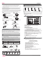
Outdoor Unit
Loading of the battery
1 Remove the battery cover;
2 Load the batteries as illustrated.
2 AAA batteries.
3 Be sure battery polarity is
4
4
correct " + "/"-";
Load the battery,then put on the cover again.
Note:
OUTLET
CONNECTING PIPING AND ELECTRICAL WIRING
INLET
DRAIN HOSE
The distance from the remote to the receiver should be less than
23 feet (7 meters) with no obstructions.
Fluorescent lights or cordless telephones will reduce the range
of the remote.
If the display is dim the remote batteries may need to be replaced.
Remote malfunctions can sometimes be corrected by removing
the batteries for a few minutes and then replacing them.
The unit pictured above is for reference only.
Your product may appear different.
Hint:
Remove the batteries if the unit won't be in use for a long period. If
there is any display after taking-out the batteries, just press reset key.
24
Domestic Air Conditioner
System Configuration
Operation
Emergency operation and test operation
Base Operation
Emergency Operation:
Use this operation only when the remote controller is defective
or lost, and with function of emergency running, air conditoner
can run automatically for a while.
When the emergency operation switch is pressed, the unit
beeps once, which means the start of this operation.
When power switch is turning on for the first time and
emergency operation starts, the unit will run automatically in
the following modes:
Remote controller
Room
Designated Timer Fan Operation
temperature temperature mode speed mode
o
78 F
o
74 F
Above 74 F
Below 74 F
o
o
No
AUTO
COOL
No
AUTO
HEAT
emergency
operation switch
Be
ep
During emergency operation it is impossible to change the
settings of temp. and fan speed,It is also not possible to
operate in timer or dry mode.
1. Unit start
Press ON/OFF on the remote controller, unit starts.
Test operation:
2. Select operation mode
COOL button:Cooling mode
HEAT button: Heating mode
DRY button: Dehumidify mode
3.Select temp.setting
button
Every time the button is pressed, temp.setting
increase 1oC / 2 o F, if kept depressed, it will
increase rapidly
Every time the button is pressed, temp.setting
decrease 1oC / 2 o F, if kept depressed, it will
decrease rapidly
Select a desired temperature.
Press
4.Fan speed selection
HI
AUTO
Air conditioner is running under displayed fan speed.
When FAN is set to AUTO, the air conditioner
automatically adjusts the fan speed according to room
temperature.
Operation
Mode
AUTO
Remote
Controller
1.Status display of air flow
2.Left and right air flow adjustment(manual)
A
U
T
O
MED
Air Flow Direction Adjustment
COOL/DRY:
Press FAN button. For each press, fan speed
changes as follows:
Remote controller:
LOW
Test operation switch is the same as emergency switch.
Use this switch in the test operation when the room temperature
is below 60 o F, do not use it in the normal operation.
Continue to press the test operation
test operation
switch
switch for more than 5 seconds.After
Be
ep
-B
you hear two beeps, release your finger
ee
p
from the switch: the cooling operation
starts with the air flow speed "Hi".
Under this operation mode,the fan motor of indoor
unit will run in high speed.
Move the vertical blade by a knob on air conditioner
to adjust left and right direction to achieve
stereoscopic air flow as the figure below.
Note
Cautions:
Under the mode of auto operation, air conditioner will
automatically select Cool or Heat operation according to
room temperature. When FAN is set to AUTO the air
conditioner automatically adjusts the fan speed according
to room temperature.
COOL
DRY
In DRY mode , when room temperature is 2 o C/4 o F degrees
less than the temperature set point, the unit will run
intermittently at LOW speed regardless of FAN setting.
HEAT
In HEAT mode, warm air will blow out after a short
period of the time due to cold-draft prevention function.
When FAN is set to AUTO, the air conditioner automatically
adjusts the fan speed according to room temperature.
FAN
In FAN operation mode , the unit will not operate in COOL or
HEAT mode but only in FAN mode, AUTO is not available in
FAN mode. And temp. setting is disabled. In FAN mode,
sleep operation is not available.
25
stereoscopic air flow
When adjusting the flap by hand,turn off the unit.
When humidity is high,condensate water might occur
at air outlet if all vertical louvers are adjusted to left or
right.
It is advisable not to keep horizontal flap at downward
position for a long time in COOLor DRY mode ,
otherwise, condensate water might occur.
Note:
When restarting the unit after it has been turned off,
the unit will keep the swing position before it stops
working.
Domestic Air Conditioner
System Configuration
Operation
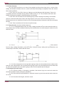
Sleep Operation
3. In AUTO mode
Press
button to enter additional options, cycle
the display to
,
will flash. And then press
enter for sleep function.
If the unit is running cooling, the sleep mode will follow
the function as in cool mode, while follow as in heat
mode.
4. In FAN mode
It has no SLEEP function.
5.Fan Speed in Sleep Mode
When the unit is set to sleep mode, the fan speed
will be set to low speed and it cannot be changed.
Note
Operation Mode
1. In COOL,DRY mode
1 hours after SLEEP mode starts,temp.will become 1OC/2 O F
higher than temp.setting.After another 1 hours,temp.rises
by 1OC / 2 O F futher. The unit will run for further 6 hours then
stops Temp. is higher than temp.setting so that room
temperature won’t be too low for your sleep.
SLEEP operation starts
POWER/QUIET Operation
SLEEP operation stops
Approx.6hrs
(1) POWER Operation
When you need rapid heating or cooling, you can use this function.
Rises 1OC/ 2 OF
1 hr
Rises 1OC/ 2 O F
1 hr
Temp.setting
Press
button to enter additional options, cycle the
display to
,
will flash,and then press
,enter to
power function. To cancel this function, please select a
Unit stop
In COOL, DRY mode
different option.
2. In HEAT mode
(2) QUIET Operation
1 hours after SLEEP mode starts,temp will become 2OC /
4 O F lower than temp.setting.After another 1 hours,temp
decrease by 2 O C / 4 O F futher.After more another 3 hours,
temp. rises by 1 O C / 2 O F futher.The unit will run for further
3 hours then stops.Temp.is lower than temp. setting so
that room temperature won’t be too high for your sleep.
Temp.setting
1 hr
When TIMER function is set, the sleep function can’t be
set up .After the sleep function is set up, if user resets
TIMER function, the sleep function will be cancelled; the
machine will be in the state of timing-on.
Unit stop
canceled.
cause the room temperature to not reach the set
temperature. If this occurs, cancel QUITE mode and set
3 hrs
SLEEP
operation starts
function, press the QUIET button again and it will be
Running the unit in QUIET mode for a long period may
Decreases 2OC/ 4 O F
3 hrs
Press QUIET button, the remote controller will show
and then achieve to the quiet function. To cancel this
Note ˖
Decreases 2OC/ 4 O F
1 hr
You can use this function when silence is needed for rest or reading.
Rises 1OC/ 2 O F
the fan speed to a higher setting.
SLEEP
operation stops
In HEAT mode
26
Domestic Air Conditioner
,
System Configuration
Operation
Timer On/Off On-Off Operation
Healthy airflow Operation
1.After unit starts, select your desired operation mode.
1.Press
2.Press TIMER button to change TIMER mode. Every
time the button is pressed, display changes as follows:
Setting for comfortable conditions.
Remote controller:
0.5h
0.5h
0.5h
TIMER ON-OFF
0.5h
TIMER OFF-ON
Then select your desired TIMER mode (TIMER ON or
TIMER OFF or TIMER ON-OFF). "
"or "
"will flash.
3.Press
/
2.The setting of healthy airflow function
Press
button to enter additional options,Press this
button continuously, the louvers location will cycle between
in the following three locations, to choose the swing location
BLANK
TIMER ON TIMER OFF
to starting
what you needed,and then press
Healthy
airflow
upwarder
button to set time.
Press the button for each time, setting time in the first
12 hours increased by 0.5 hour every time, after 12
hours,increased by 1 hour every time.
Press the button for each time, settiing time in the first
12 hours decreased by 0.5 hour every time, after 12
hours,decreased by 1 hour every time.
It can be adjusted within 24 hours.
Healthy
airflow
downwarder
button to confirm.
Present
position
3.To cancel of the healthy airflow function
Press
button to enter additional options,Press this
button continuously, the louvers location will cycle between
the three locations again,and then press
button to
cancel.
4.Confirm timer setting
Notice: Do not direct the horizontal by hand. This may
After adjusting the time,press
button and confirm
the time the ON or OFF button will not flash any more.
cause the louver to run incorrectly and not match the
display. If the louver is not running correctly, stop the unit
for a minute and then restart and adjust remote controller.
5.Cancel timer setting
Press the timer button until the time display eliminated.
Note:
1.After setting the healthy airflow function, the position
Hints:
louver is fixed.
After replacing batteries or a power failure happens, time
2.In heating, it is better to select the
mode.
setting should be reset.
3.In cooling, it is better to select the
mode.
According to the Time setting sequence of TIMER ON or
TIMER OFF, either Start-Stop or Stop-Start can be achieved. 4.In cooling and dry, using the air conditioner for a long
time under the high air humidity, condensate water may
occur at the grille .
27
Domestic Air Conditioner
System Configuration
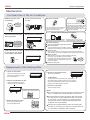
Maintenance
For Smart Use of The Air Conditioner
Setting of proper room
temperature
Remote Controller
Do not block the air inlet
or outlet
Indoor Body
Proper
temperature
wipe the air conditioner by using a
soft and dry cloth.For serious stains,
use a neutral detergent diluted with
water.Wring the water out of the
cloth before wiping,then wipe off the
detergent completely.
Do not usewater,wipe the controller
with a dry cloth.Do not use glass
cleaner or chemical cloth.
Do not use the following for cleaning
Use the timer effectively
Close doors and windows
during operation
Gasoline,benzine, thinner or cleanser
may damage the coating of the unit.
Hot water over 40 O C(104O F) may
cause discoloring or deformation.
Air Filter cleaning
During cooling operation
prevent the penetration
of direct sunlight with
curtain or blind
Open the inlet grille by pulling it upward.
Remove the filter.
Push up the filter's center tab slightly until it is
released from the stopper, and remove the filter downward.
Clean the filter.
Use the louvers effectively
If the unit is not to be used
for a long time, turn off the
power supply main switch.
Use a vacuum cleaner to remove dust, or wash the filter with water.
After washing, dry the filter completely before putting it back in the unit.
Attach the filter.
Attach the filter correctly so that the "FRONT" indication
is facing to the front.Make sure that the filter is
completely fixed behind the stopper.If the right
and left filters are not attached correctly, that
may cause defects.
OFF
Once every
two weeks
Close the inlet grille.
Replacement of Air Purifying Filter
1.Open the lnlet Grille
4.Attach the standard air filter
Prop up the inlet grille by using the
(Necessary installation)
grille-support located an the right
side of the indoor unit.
ATTENTION:
The white side of the photocatalyst air purifying filter
face outside,and the black side face the unit The green
side of the bacteria-killing medium air purifying filter face
outside,and the white side face the unit.
2.Detach the standard air filter
Slide the knob slightly upward to
release the filter, then withdraw it.
5.Close the Inlet Grille
Close the Grille securely
NOTE:
Detach old Air Purifying Filter
The photocatalyst air purifying filter will be solarized in fixed
time. In normal family, it will be solarized every 6 months.
The bacteria-killing medium air purifying filter will be used
for a long time,no need for replacement. But in the period
of using them ,you should remove the dust frequently by
using vacuum cleaner or flapping them lightly,otherwise ,
its performance will be affected.
3.Attach Air Purifying Filter
Put air purifying filter into the
right and left filter frames.
Please keep the bacteria-killing medium air purifying filter
cool and dry. Avoid long term exposure to sunlight when not
in use its ability of sterilization will be reduced.
28
Domestic Air Conditioner
System Configuration
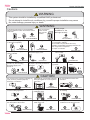
Cautions
WARNING
This system should be installed by a qualified HVAC professional.
Do not attempt to install the air conditioner by yourself improper installation may cause
fire, water leakage, personal injury or death.
WARNING
If something abnormal occurs immediately
stop the operation button and contact service
technician.
Check proper
installation of the
drainage securely
Use an exclusive
power source
with a circuit
breaker
STRICT
ENFORCEMENT
OFF
Connect power supply cord
to the outlet completely
STRICT
ENFORCEMENT
Use the proper voltage
STRICT
STRICT
ENFORCEMENT
ENFORCEMENT
Take care not to damage
Do not use power supply
the power supply cord.
cord in a bundle.
PROHIBITION
PROHIBITION
PROHIBITION
Do not start or stop the
operation by disconnecting
the power supply cord
and so on.
1.Do not use power supply cord extended
or connected in halfway
2.Do not install in the place where there is any
possibility of inflammable gas leakage around the unit.
3.Do not get the unit exposed
to vapor or oil steam.
PROHIBITION
Do not insert objects into the air
inlet or outlet.
Do not channel the air flow directly Do not try to repair
at people, especially at infants or
by yourself.
the aged.
PROHIBITION
Connect the earth
cable.
earthing
PROHIBITION
CAUTION
Do not use for the purpose of storage of
food, art work, precise equipment,
breeding, or cultivation.
PROHIBITION
Do not install the unit near a fireplace
or other heating apparatus.
Take fresh air occasionally especially
when gas appliance is running at the
same time.
STRICT
ENFORCEMENT
Check good condition of the
installation stand
PROHIBITION
Do not place animals or plants in
the direct path of the air flow
Do not operate the switch with
wet hand.
PROHIBITION
Do not pour water onto the unit
for cleaning
PROHIBITION
PROHIBITION
Do not place any objects on or
climb on the unit.
PROHIBITION
PROHIBITION
29
Do not place flower vase or water
containers on the top of the unit.
PROHIBITION
Domestic Air Conditioner
System Configuration
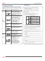
Cautions
Trouble shooting
Before asking for service, check the following
first.
Phenomenon
The system
does not restart
immediately.
Noise is heard
Normal
Performance
inspection
Smells are
generated.
Mist or steam are
blown out.
Do not obstruct or cover the ventilation grille of the air
conditoner.Do not put fingers or any other things into the
inlet/outlet and swing louver.
Cause or check points
Do not allow children to play with the air conditioner.In no
case should children be allowed to sit on the outdoor unit.
When unit is stopped, it won't restart
immediately until 3 minutes have
elapsed to protect the system.
When the electric plug is pulled out
and reinserted, the protection circuit
will work for 3 minutes to protect the
air conditioner.
During unit operation or at stop,
a swishing or gurgling noise may
be heard.At first 2-3 minutes after
unit start, this noise is more noticeable.
(This noise is generated by
refrigerant flowing in the system.)
During unit operation, a cracking
noise may be heard.This noise is
generated by the casing expanding
or shrinking because of
temperature changes.
Should there be a big noise from
air flow in unit operation, air
filter may be too dirty.
This is because the system
circulates smells from the interior
air such as the smell of furniture,
paint, cigarettes.
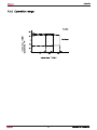
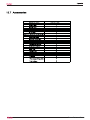
Specifications
The refrigerating circuit is a sealed system.
The machine is adaptive in following situation
1.Applicable ambient temperature range:
Indoor
Cooling
Maximum:D.B/W.B 89.6 /73.4
Minimum:D.B/W.B 67 /57
Maximum:D.B/W.B 115 /75
67 /57
Maximum:D.B
80.6
Minimum: D.B
32
Outdoor Minimum: D.B
Indoor
Heating
Outdoor
Maximum:D.B/W.B 75 /65
Minimum:D.B/W.B 19.4
Outdoor Maximum:D.B/W.B 75 /65
(INVERTER)
Minimum:D.B
5
2. If the power supply cord is damaged, it must be replaced by the
manufacturer or its service agent or a similar qualified person.
3.If the fuse of indoor unit on PC board is broken,please change
it with the type of T. 3.15A/ 250V. If the fuse of outdoor unit is
broken,change it with the type of T.25A/250V
During COOL or DRY operation,
indoor unit may blow out mist.
This is due to the sudden cooling
of indoor air.
4. The wiring method should be in line with the local wiring standard.
In dry mode, fan
speed can’t be
changed.
Multiple
check
Poor cooling
In DRY mode, when room temperature
becomes lower than temp.
setting+2 oC,unit will run
intermittently at LOW speed
regardless of FAN setting.
5. After installation, the power plug should be easily reached.
6. When replacing batteries, the batteries removed should be disposed
of properly.
Is power plug inserted?
Is there a power failure?
Is fuse blownout?
7. The appliance is not intended for use by young children without
supervision.
Is the air filter dirty?
Normally it should be cleaned
every 15 days.
Are there any obstacles before
inlet and outlet?
Is temperature set correctly?
Are there some doors or
windows left open?
Is there any direct sunlight
through the window during the
cooling operation?(Use curtain)
Are there too much heat sources
or too many people in the room
during cooling operation?
8. Young children should be supervised to ensure that they do not play
with the appliance.
9. Please employ the proper power plug, which fit into the power supply
cord.
10. The power plug and connecting cable must have acquired the local
attestation.
11.In order to protect the units,please turn off the A/C first, and at least
30 seconds later, cutting off the power.
30
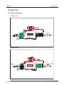
Domestic Air Conditioner
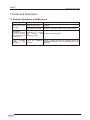
Functions and control
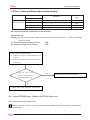
7.Codes and Description
7.1.Problem Symptoms and Measures
Symptom
Check Item
None of the units
Check the power supply.
Details of Measure
Check to make sure that the rated voltage is
supplied.
operates
Check the indoor PCB
Check to make sure that the indoor PCB is broken
Equipment
operates but does Diagnosis by service
not cool, or does port
pressure
and Check for insufficient gas.
not heat (only for operating current.
heat pump)
Large operating Check the installation Check to make sure that the required spaces for
installation (specified in the Technical Guide, etc.) are
noise
and condition.
provided.
vibrations
31
Domestic Air Conditioner
Codes and description
7.2 Error Codes and Description indoor display
Code indication
Description
indoor
Indoor Malfunction
Reference
Page
E1
Room temperature sensor failure
32
E2
Heat-exchange sensor failure
32
E4
Indoor EEPROM error
32
E14
Indoor fan motor malfunction
33
The code indication that is listed above is the main fault
Troubleshooting
Caution Be sure to turn off power switch before connect or disconnect connector, or else parts damage
may be occurred.
E1: Room temperature sensor failure
E2: Heat-exchange sensor failure
CN6
CN6
Pull the sensor out of the mainboard
1)
Measure the value of resistance Between its two
2)
Measure the temperature at the room temperature
jumpers
sensing head.
Check the value of the
YES
Sensor is broken,replace it with new sensor
sensor to see whether the
sensor is damaged or not?
NO
The indoor PCB is broken, replace with new indoor PCB
E4˖Indoor EEPROM error˖Replace the PCB of indoor unit
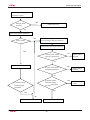
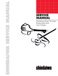
E14: Indoor fan motor malfunction
Notes: When the unit is on, don’t pull out or insert the terminal of the motor (CN26), or else the motor
would be damaged.
32
Domestic Air Conditioner
Codes and Description
Turn off power supply and
rotate fan by hand
Does fan rotate
NO
Replace fan motor
smoothly?
Yes
Turn power ON and operate fan
No
Does it rotate?
Turn off power supply and disconnect fan
motor connector, then turn power ON
Check output of fan motor connector
Yes
Is motor power voltage
NO
DC310V g enerated?
Replace indoor
unit PCB
Yes
Stop fan motor
Is motor control power
NO
voltageDC15Vgenerat
Replace indoor
unit PCB
Yes
Is rotation number
Is rotation number
command voltage
command pulse
DC1 6V generated?
Yes
Replace fan
motor
generated?
No
Yes
No
Replace indoor fan motor
Replace indoor unit PCB
33
Domestic Air Conditioner
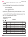
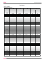
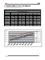
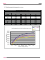
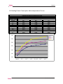
8.1 Cooling Capacity-temperature Curves
HSU24VHK-G&W performance curves
cooling value-temerature table
outdoor temp.(humidity 46%)
indoor temp.
DB/WB
64̧
68̧
77̧
90̧
95̧
104̧
109̧
115̧
64/54̧
19712
19360
18700
17600
17160
16192
15400
14476
64/57̧
21120
20460
20020
18920
18154
16940
16280
15576
68/59̧
21384
21120
20680
20020
19166
18040
17160
16280
72/61̧
22264
22000
21560
20592
19800
18700
18040
17362
77/64̧
23584
23320
22880
21648
20900
20240
19254
18304
80/67̧
25080
24640
23672
23056
22000
21120
20152
19360
86/72̧
26048
25784
25080
24024
23540
22660
22000
21208
90/73̧
26664
26136
25520
24904
24200
23320
22880
22440
90/75̧
27148
26840
26400
25960
25300
24464
23760
22968
64̧
68̧
77̧
90̧
95̧
104̧
109̧
115̧
34
Domestic air conditioner
8.2 Cooling Power Consumption Value-temperature Curves
HSU24VHK-G&W performance curves
power consumption value-temp.table
outdoor temp.(humidity 46%)
indoor temp.
DB/WB
64̧
68̧
77̧
90̧
95̧
104̧
109̧
115̧
64/54̧
1449
1528
1608
1688
1756
1865
1956
2053
###
64/57̧
1507
1575
1648
1738
1811
1919
2021
2097
###
68/59̧
1557
1641
1702
1793
1865
1974
2064
2133
###
72/61̧
1615
1684
1746
1829
1919
2028
2111
2173
###
77/64̧
1677
1724
1771
1869
1956
2082
2158
2227
###
80/67̧
1731
1775
1840
1930
2010
2137
2245
2300
###
86/72̧
1771
1829
1890
1974
2064
2227
2354
2434
###
90/73̧
1822
1883
1977
2028
2119
2282
2390
2513
###
90/75̧
1883
1941
1992
2072
2173
2336
2484
2608
###
power consumption-temp.curves
2800
power consumption(w)
2600
64̧
2400
68̧
2200
77̧
2000
90̧
95̧
1800
104̧
1600
109̧
1400
115̧
1200
indoor tempe.(DB/WB)
35
Domestic air conditioner
8.3 Heating capacity-temperature curves
HSU24VHK-G&W performance curves
heating capacity and indoor/outdoor temp.table
indoor temp.(humidity 46%)
outdoor temp.
DB/WB
59̧
68̧
77̧
5̧
12320
10951
9615
23̧
19148
17339
15156
41̧
22815
20778
18578
45/43̧
25096
22000
20044
59̧
26074
23222
20370
68̧
26889
23630
21267
77̧
27867
24037
22163
59̧
68̧
heating capacity and indoor/outdoor temp.curves
77̧
30000
conoling capacity(Btu)
27000
24000
21000
18000
15000
12000
9000
5̧
23̧
41̧
45/43̧
59̧
68̧
77̧
outdoor tempe.(DB/WB)
36
Domestic air conditioner
Capacity
8.4 Heating Power Consunption Value-temperature Curves
HSU24VHK-G&W performance curves
power consumption value-temp.table
indoor temp.(humidity 46%)
outdoor temp.
59̧
68̧
77̧
1307
1601
1405
1709
1526
1817
41̧
45/43̧
1752
1928
2023
1830
2010
2190
59̧
68̧
1863
2026
2239
1896
2059
2281
77̧
1928
2092
2340
DB/WB
5̧
23̧
̧
̧
̧
·
'%:%
̧
̧
̧
37
̧
̧
̧
Domestic air conditioner
Sound level
8.5 Sound level
HSU24VHK-G&W
Sound pressure level
208~230V,60HZ
Model
HSU24VHK-G&W
Measureing location
sound power level
Location of microphone
(cooling/heating)
Cooling/Heating
H
M
L
51
48.5
46
60
Indoor
Outdoor
Cooling
Octave band cenrer frequency(HZ)
38
Domestic Air Conditioner
Installations
9.Installation Manual of Room Air Conditioner
Preparation
Selection of Installation Place
Necessary Tools for Installation
ƽ
ƽ
ƽ
ƽ
ƽ
ƽ
Indoor Unit - Select a plocation that is
ƽ Robust not causing vibration, where the body can be supported sufficiently.
ƽ Not affected by heat or steam generated in the vicinity, where inlet and outlet of the
ƽ Torque wrench
(17mm,22mm,26mm)
ƽ Pipe cutter
ƽ Flaring tool
ƽ Knife
ƽ Measuring tape
ƽ Reamer
Hammer
Nipper
Hacksaw
Hole core drill
Spanner(17,19 and 26mm)
Gas leakage detector or
soap-and-water solution
unit are not disturbed.
ƽ Possible to drain easily, where piping can be connected with the outdoor unit.
ƽ Where cold air can be spread in a room evenly.
ƽ Nearby a power receptacle. (Refer to drawings).
ƽ Place where the distance of more than lm from televisions, radios, wireless apparatuses
and fluorescent lamps can be left.
Power Source
ƽ In the case of fixing the remote controller on a wall, place where the indoor unit can
receive signals when the fluorescent lamps in the room are in use.
ƽ Before inserting power plug into receptacle, check the voltage without fail.
The power source is the same as the corresponding name plate.
ƽ Install an exclusive branch circuit of the power.
ƽ A receptacle shall be set up in a distance where the power cable can be
reached.Do not extend the cable by cutting it.
Outdoor Unit - Select a plocation that is
ƽ Not less affected by rain or direct sunlight and is sufficiently ventilated.
ƽ Strong enough to bear the unit, where vibration and noise are not increased.
ƽ Place, where discharged wind and noise do not cause a nuisance to the neighbors.
ƽ Place, where a distance marked is available as illustrated in the above figure.
Drawing for the installation of indoor and outdoor units
The models adopt HC FC free refrigerant R410A
Attention must be paid to
the pitch of drain hose
Optional parts for piping
more than 10cm
(3 7/8)
A Non-adhesive tape
B Adhesive tape
C Saddle (L.S) with screws
Connecting electric cable
D
for indoor and outdoor
E Drain hose
F Heating insulating material
more than 10cm
(3 7/8)
G Piping hole cover
Arrangement of piping
directions
Floor xing dimensions of the
outdoor unit (Unit:mm / inch)
more than 10cm
(3 7/8)
340
(13 1/2)
A
Rear left
For: HSU18VHK-W
Rear
right
113.5
(4 1/2)
Right
633
(24 7/8)
113.5
(4 1/2)
C
Below
For: HSU24VHK-W
more than 15cm
(5 7/8)
184
(7 1/4)
more than 20cm
(7 7/8)
3 80
(14 15/16)
Left
580
(22 7/8)
184
(7 1/4)
Fixing of outdoor unit
The marks from A to
G in the gure are the
parts numbers.
The distance between
the indoor unit and the
oor should be more
than 2m.
Fix the unit to concrete or block
with bolts (10mm) and nuts rmly
and horizontally.
When tting the unit to wall
surface, roof or rooftop, x
a supporter surely with nails
or wires in consideration of
earthquake and strong wind.
If vibration may affect the
house, x the unit by attaching a
more than 60cm
(23 5/8)
more than 25cm
(9 7/8)
vibration-proof mat.
Please be subject to the actual product purchased , the above picture is just for your reference.
Read this manual before installation
Explain suf ciently the operating means to the user according to this manual.
39
Domestic Air Conditioner
Installations
1. Insert the drain hose into the dent of heat insulation materials of indoor unit.
2. Insert the indoor/outdoor electric cable from backside of indoor unit, and pull it
out on the front side, then connect them.
3. Coat the flaring seal face with refrigerant oil and connect pipes.
Cover the connection part with heat insulation materials, cover with adhesive tape.
Accessory parts
Remote controller (1)
Drain hose (1)
AAA dry battery (2)
Cushion (4)
Mounting plate (1)
Drain-elbow (1)
Indoor/outdoor electric cable
Plastic cap (4)
Ø4X25 Screw (4)
Heat insulation
material
Piping
Lid for right
piping
Pipe supporting plate (1)
Lid for left piping
Pipe supporting
plate
Drain hose
Lid for under piping pipe
Selection of pipe
Fix with adhesive tape
For 18K
Type
Liquid pipe (Ø)
Gas pipe (Ø)
6.35mm(1/4”)
ƽ Indoor/outdoor electric cable and drain hose must be bound with refrigerant
piping with protecting tape.
For 24K
9.52mm(3/8”)
[ Other direction piping ]
ƽ Cut away, with a nipper, the lid for piping according to the piping direction and
then bend the pipe according to the position of wall hole. When bending, be
careful not to crash pipes.
ƽ Connect beforehand the indoor/outdoor electric cable, and then pull out the
connected to the heat insulation of connecting part specially.
12.7mm(1/2”) 15.88mm(5/8”)
NOTE˖The thickness of the pipe must be 0.8mm(1/16”) at least.
Indoor unit
Fitting of the Mounting Plate and Positioning of the wall Hole
Fixing the indoor unit body
When the mounting plate is first fixed
ƽ Hang the unit body securely onto the upper notches of the
mounting plate. Move the body from side to side to verify
its secure fixing.
ƽ In order to fix the body onto the mounting plate,hold up
the body aslant from the underside and then put it down
perpendicularly.
1. Carry out, based on the neighboring pillars or lintels, a proper leveling for the plate
to be fixed against the wall, then temporarily fasten the plate with one steel nail.
2. Make sure once more the proper level of the plate, by hanging a thread with a
weight from the central top of the plate, then fasten securely the plate with the
attachment steel nail.
3. Find the wall hole location A using a measuring tape
mounting plate
mm
(3 9/16)
Unloading of indoor unit body
ƽWhen you unload the indoor unit, please use
A=150mm
your hand to raise the body, then lift the
bottom of the body outward slightly
and lift the unit until it leaves the
mounting plate.
mm
(5 7/8)
(2 3/4)
mounting plate
Connecting the indoor/outdoor Electric Cable
A=150mm
(5 7/8)
35mm
(5 7/8)
mm
(2 3/4)
Removing the wiring cover
ƽ Remove terminal cover at right bottom corner of indoor unit, then take
When the mounting plate is fixed side bar and lintel
off wiring cover by removing its screws.
ƽ Fix to side bar and lintel a mounting bar, Which is separately sold, and then
fasten the plate to the fixed mounting bar.
ƽ Refer to the previous article, “ When the mounting plate is first fixed “, for the
position of wall hole.
When connecting the cable after installing the indoor unit
Making a Hole on the Wall and Fitting the Piping Hole Cover
1. Insert from outside the room cable into left side of the wall
hole, in which the pipe has already existed.
2. Pull out the cable on the front side, and connect the cable
making a loop.
ƽ Make a hole of 70 mm(2 3/4)in diameter, slightly descending to outside the wall.
ƽ Install piping hole cover and seal it off with putty after installation
Wall hole
Pitch downward for drainage
When connecting the cable before installing the indoor unit
Ø70mm
(2 3/4)
Indoor side
ƽ
ƽ
ƽ
Outdoor side
Thickness of wall
Insert the cord from the back side of the unit, then pull it out on the front side.
Fasten the unit wire harness to the conduit holder using the lock nut.
Position the conduit holder to its original state using screw.
Installation of the Indoor Unit
Drawing of pipe
[ Rear piping ]
Conduit holder
ƽ Draw pipes and the drain hose, then fasten them with the adhesive tape
Cut the 6 slit sear
[ Left・Left-rear piping ]
Note
ƽ In case of left side piping, cut away, with a nipper, the lid for left piping.
ƽ In case of left-rear piping, bend the pipes according to the piping direction to
the mark of hole for left-rear piping which is marked on heat insulation materials.
40
When connecting the cable, confirm the terminal number of indoor and
outdoor units carefully. If wiring is not correct, proper operation can not
be carried out and will cause damage to the units.
Domestic Air Conditioner
Installations
Ensure that on dirt or debris enters the pipe.
The standard pipe length is 7m(27 9/16)
. If it is over 7m(27 9/16), the function of
the unit will be affected. If the pipe has to be lengthened, the refrigerant should
be charged, according to 50 g/m(0.045 oz/inch).But the charge of refrigerant must
be conducted by professional air conditioner servicer. Before adding additional
perform air purging from the refrigerant pipes and indoor unit using a vacuum
refrigerant, pump,then charge additional refrigerant.
CAUTION
Outdoor unit
Indoor unit
B
B
A
A
Indoor unit
Outdoor unit
Control wiring :
≥3wire 18AWG
●
●
Outdoor unit
≥3wire 16AWG
B
Indoor unit
A
Oil trap
Indoor unit
In case the elevation A is more
than 5m, oil trap shoud be
installed every 5~7m
Max. Length: Bmax= 0m
In case the pipe length B is
more than 10m, the refrigerant
should be charged, according
to 50 g/m.
Power
cable
Connection
Outdoor unit
HSU18VHK-W Power cable:
HSU24VHK-W Power cable:
●
●
Max.Elevation: Amax=15 m
Take off the panel(top), by removing the 5 screws.
Remove the plugs on the conduit plate.
Temporarily mount the conduit tubes on the conduit plate.
Connect both the power supply and unit wire harness to
the corresponding terminals on the terminal board.
Ground the unit in accordance with local codes.
Allow several extra inches of wire for making wiring
connections.
Use lock nuts to secure conduit tubes.
2 Wire with ground 14AWG
2 Wire with ground 14AWG
1. If the fuse on PC board is broken please change it with the type of
T. 3.15A/250V (indoor unit), 25A/250V(outdoor unit).
2. The wiring method should be in line with the local wiring standard.
3. After installation, the power plug should be easily reached.
4. A breaker should be incorporated into fixed wiring. The breaker should be
all-pole switch.
Outdoor unit
Attaching Drain-Elbow
Installation of Outdoor Unit
Install according to
If the drain-elbow is used,
please attach it as figure. (Note:
Only for heat pump unit.)
Drawing for the installation of indoor and outdoor units
Purging Method:To use vacuum pump
Connection of pipes
1.
To bend a pipe, be careful not to crush the pipe,
and the bending radius should be 30(1 1/6) to 40 mm(1 4/7) or longer.
Connecting the pipe of gas side first makes working easier.
Detach the service port’s cap of 3-way valve, the valve rod’s cap for 2-way valve
and 3-way’s, connect the service port into the projection of charge hose (Iow)
for gaugemanifold. Then connect the projection of charge hose (center) for gaugemanifold into vacuum pump.
The connection pipe is specialized for R410A.
Half union
Flare nut
2. Open the handle at Iow in
gaugemanifold, operate vacuum pump. If the scalemoves of gause (Iow) reach vacuum condition in a moment, check 1. again.
Forced fastening without careful centering may
damage the threads and cause a leakage of gas.
3. Vacuum for over 15min. And check the gauge which should read -0.1MPa
Pipe Diameter(ǿ)
Spanner
Torque wrench
(76 cm Hg) at Iow pressure side. After the completion of vacuuming, close the
handle ‘Lo’ in gaugemanifold and stop the operation of the vacuum pump. Check
condition of the scale and hold it for 1-2min. If the scale-moves back in spite of
tightening, make flaring work again, the return to the beginning of 3 .
Fastening torque
Liquid side6.35mm(1/4")
18N.m
Liquid/Gas side9.52mm(3/8")
42 N.m
Gas side 12.7mm(1/2")
55N.m
Gas side 15.88mm(5/8")
60 N.m
4. Open the valve rod for the 2-way valve counterclockwise to 90 degrees.
After 6 seconds, close the 2-way valve and make the inspection of gas leakage.
4
Domestic Air Conditioner
Installations
5. No gas leakage?
In case of gas leakage, tighten parts of pipe connection. If leakage stops,
then proceed step 6. If leak continues, remove the refrigerant used for the
leakage check and flare tubes again. Repeat vacuum and leak and if no
leakage, proceed to step 6.
On Drainage
ƽ Please install the drain hose so as to be downward slope without fail.
ƽ Please don’t do the drainage as shown below.
6. Detach the charge hose from the service port, open 2-way valve and 3-way. Turn
Less than
5cm
the valve rod counterclockwise.
leakage, turn the service port’s cap, the valve rod’s cap for 2-way
valve and 3-way’s a little more than the point where the torque increases suddenly.
7.To prevent the gas
8. After attaching the each caps, check the gas
Step 1.
leakage around the caps.
Step 2.
2-way valve Liquid Side
3-way valve Gas Side
It becomes The end is imm- It waves. The gap with the There is the bad
high midway. ersed in water.
ground is too smallsmell from a ditch
ƽ Please pour water in the drain pan of the indoor unit, and confirm that drainage
is carried out surely to outdoor.
Open
ƽ In case that the attached drain hose is in a room, please
apply heat insulation to
it without fail.
Gaugemanifold(for R410A)
Anti countercurrent joint
Ƶ Refrigerant charge label
Step 3.
Contains fluorinated greenhouse gases
covered by the Kyoto Protocol
Close
Tube(for R410A)
Step 4.
Vacuum pump(for R410A)
Step 6.
2-way valve
2-way valve
3-way valve
R410A
1=
kg
2
2=
kg
1+2=
kg
3-way valve
1
A
B
C
O
Open 90
F
2-way valve
3-way valve
Step 7.
Valve rod cap
Valve rod cap
Service port cap
CAUTION
ƽ If the refrigerant of the air conditioner leaks, it is necessary to discharge all the
refrigerant. Vacuum first, then charge the liquid refrigerant into air conditioner
according to the amount marked on the name plate.
ƽ Please do not let other cooling medium, except specified one (R410A), or air
enter into the cooling circulation system. Otherwise, there will be abnormal
high pressure in the system casuing damage and possibly personal injuries.
Power Source Installation
ƽ The power source must be exclusively used for air conditioner. (Over I0A)
ƽ In the case of installing an air conditioner in a moist place, please install an earth leakage breaker (GFCI).
ƽ For installation in other places, use a circuit breaker as far as possible.
A
Ƶ Check for Installation and Test Run
Cutting and Flaring Work of Piping
ƽ Pipe cutting is carried out with a pipe cutter and burs must
ƽ After inserting the flare nut, flaring work is carried out.
Check Items for Test Run
Conventional flare tool
Clutch-type
clutch-type(Rigid-type) Wing-nut type (Imperial-type)
1.0~1.5mm
3/76 ~1/17 inch
1.Cut pipe
Flare tooling die
3.Insert the flare nut
Correct
Ƶ Please kindly explain to our customers how to operate
through the instruction manual.
be removed.
Flare tool for R410A
0~0.5mm
0~1/51 inch
E
This product contains fluorinated greenhouse gases covered by
the Kyoto Protocol. Do not vent into the atmosphere.
Refrigerant type:R410A
GWP* value:1975
GWP=global warming potential
Please fill in with indelible ink,
•1
the factory refrigerant charge of the product
•2
the additional refrigerant amount charged in the field and
• 1+2 the total refrigerant charge
on the refrigerant charge label supplied with the product.
The filled out label must be adhered in the proximity of the product
charging port (e.g. onto the inside of the stop valve cover).
A contains fluorinated greenhouse gases covered by the Kyoto
Protocol
B factory refrigerant charge of the product: see unit name plate
C additional refrigerant amount charged in the field
D total refrigerant charge
E outdoor unit
F refrigerant cylinder and manifold for charging
2-way valve 3-way valve
D
Put check mark
in boxes
Gas leak from pipe connecting?
Heat insulation of pipe connecting?
Are the connecting wirings of indoor and outdoor firmly
inserted to the terminal block?
Is the connecting wiring of indoor and outdoor firmly fixed?
Is drainage securely carried out?
Is the earth line securely connected?
Is the indoor unit securely fixed?
Is power source voltage abided by the code?
Is there any noise?
Is the lamp normally lighting?
Are cooling and heating (when in heat pump) performed normally?
Is the operation of room temperature regulator normal?
1.5~2.0mm
1/17 ~1/8 inch
2.Remove burs
4.Flare pipe
Incorrect
Lean
Damage of flare Crack
Partial
Too outside
42
Domestic Air Conditioner
Piping diagrams
10.Appendix
10.1 Piping Diagrams
Cooling mode
Heating mode
43
Domestic Air Conditioner
44
&1
0
&(175$/
&21752/
5(&(,9(5
',63/$<
3,3(7(036(1625
$0%,(177(036(1625
Indoor
::+,7(
%%/$&.
55('
%/%/8(
%5%52:1
<*<(//2:
*5((1
Wiring diagrams
10.2 Wiring Diagrams
Domestic Air Conditioner
N O T E : 1 .T h e p a rts ķ a re o p tio n a l.
Wiring diagrams
Outdoor
45
Domestic air conditioner
Wiring diagrams
10.3 Wiring diagrams
Circuit Diagram
3 6$$.
+5V
&
5 .
1
(
2
8)9
7-&
(
8)9
&1
X)
5
.
5
.
1 SLSH
2 URRP
3
4
&
X)
E16
4.7uF/16V R135
KZ
R136
C14
4.7K- 1%
0.001UF
1
2
%%;+$UHG
5
.
60
64
63
(
8)9
VCC/AVCC
VREF
VCC/AVCC
8
59
VSS/AVSS
VSS/AVSS
24
15
P6_7/INT3/RXD1
+5V
5
&1
$
+5V
network
1
2
p_12
&
X)
&
X)
5
p_11
reserve 5 .
&
X)
%%;+$
R switch
&
X)
2
P5_3/TRCIOC
P5_2/TRCIOB
P5_1/TRCIOA/TRCTRG
P5_0/TRCCLK
P5_4/TRCIOD
P1_6/CLK0
P2_3/TRDIOD0
P3_4/SDA/SCS
.
8
7
6
5
5
. .
E2 clock
E2 data
5 ¡
4
5
0.1uF
1000uF-35V-105?
470uF-16V
5
1
ZD3
2
10Ω-1/4W
12V-1W-1N4742A
. 5
5
390Ω
IC4
+5V
5
&
10K
X)9
TLP421
(
R10
47uF-50V-105?
(
&<
reserve
&<
2.2nF/250V 2.2nF/250V
+12V
(
8)9"
D23
D22
p_43
R72 470Ω
p_46
compressor
4
2
1
3
2
4
icon
RLS4148
D21
RLS4148
B5B-XH-A-blue
1
$
4.7K
1
2
3
4
5
self-cleanning step motor
R75 4.7K
R78 470Ω
R77 4.7K
Icon
p_1
CN54
.
1$&&
R71
R76 470Ω
p_47
1
&21
,FRQ RXWSXW ZLUH
1
$
R61 4.7K
R67 470Ω
D20
RLS4148
1
$
p_42
1
&21
,FRQ RXWSXW ZLUH
&1
RLS4148
1
$
3$&
.
1$&&
5
4.7uF-50V-105?
(
10K
TLP421
&1
FRPSUHVVRU ZLUH
.
15
indoor fan
.
18V-1W-1N4746A
1Ω-1/2W
3
0.1uF
(
4.7uF-50V-105?
27Ω-1/4W
22uF-25V-105?
ZD1
IC10
(
5
.
&
8)
R59
5
CN26
5 .
output
7 fan
fan feedback
6
TLP421
5
4
VCC
3
2
1
VS
B7B-XH-A
.
4
100K-1/4W
R6
(
1A-800V-500ns-FR106
IC2
&
1
D28
RLS4148
+5V
&
X)
elec-heating wire
D27
RLS4148
5
4
3
2
1
%%3+.
1 &1EODFN
elec-heating
1
$
R81 2K
D24
RLS4148
1
3
2
4
CN49
1
2
3
4.7K
N
ST
WF
1
2
3
%39+EOXH˅
R80
+12V
B3B-XH-A
.
D29
RLS4148
1$&&
3
1
&21
1
)UHVK DLU ZLUH
outdoor fan
4
2
D30
.
1$&&
3
1
RLS4148
&1
+12V
IC3
1 &21ZKLWH
D26
RLS4148
5
4
3
2
1
R step motor
%%;+$
OUT
elec-heating wire
.
D25
RLS4148
ST
&1
+12V
+5V
GND
D8
C430.1uF/50V
CX1
0.1uF-275VAC
/$%&
10
9
8
7
6
5
4
3
2
1
5
.
&
D7
4
3
2
1
+12V
220V-N
+12V
5
ICE2A265
RV1
TVR14561*
FUSE1
T3.15A/250VAC
&1
+12V
VCC
1.5A-7805
IN
3A-200V-ER302
4
3
2
1
1N5399
CH1 1
250 L
9
10
11
12
13
14
15
16
HS1
ZD2
6
R9
D1
D6
5
6
7
8
1N5399
+12V
&
X)
,&
8
7
6
5
4
3
2
1
VCC
18V-1W-1N4746A
5
6
7
8
32mH-0.35A-LB2271
+5V
10Ω-1/4W
10Ω-1/4W
330K-2W
47K-2W
LX1
4.7nF-275VAC
1A-800V-500ns-FR106
100uF-450V-105?
D2
0.1uF-275VAC
1N5399
(
220V-L
1
6&.
%((33.0(3<
(
2
3
4
5
D3
1N5399
5
.
%8==
BCK-6-FE1901
1 T1 7 10uF-25V-105?
5
&
reserve
D4
GG
5 . &
X)
5
.f
E17
4.7uF-16V
IC6
C44 5
220V-N
&
X)
ST
RG2
p_11
p_12
p_42
p_43
p_46
p_47 .
5
.
5
5
.
5
.
.
5
.
5
1.5K-1/4W
D5
17&
Power circuit
.
BUZZ
5
VS
+5V
5 .
P4_3/XCIN
P4_4/XCOUT
5
SCK-4R72
5.
&
X)
RG1
R5F212A7SNFA
1A-800V-500ns-FR106
5
5
5
L step motor
X)
& ,&
1 A0
VCC
2
WP
3 A1
SCL
4 A2
GND SDA
$7&%
+5V
5 .
1
2
P1_5/RXD0
P1_4/TXD0
+5V
5
&1
network input 26
network output 27
5 ¡
5 .
%%;+$EOXH
P3_2/(INT2)
+5V
&
X)
reserve
L switch
45
.
5 ¡
1
2
3
4
5
.
&1
5
.
5
.
2
1
GND +12
A7
B7
outdoor fan
A6
B6
fresh air
A5
B5
A4
B4
A3
B3
A2
B2
A1
B1
8/1$
&
,&
.
X)
38 5
8 GND +12 9
+12V
22
7
10
indoor fan .
B7 11
39
6 A7
5
A6
B6 12
.
40
5
5
A5
B5
5
.
50
4 A4
13
B4 14
5
.
51
3
B3 15
5
.
52
2 A3
B2 16
5
.
53
1 A2
A1
B1
+5V
.f
+12V
35
8/1$
5
&
X)
25
,&
-
model select
8
9
GND +12
.
12 5
7
10
B7
compressor
.
135
6 A7
A6
B6 11
elec-heating
145
5
12
.
B5 13
15 5
4 A5
.
A4
B4
11 5
3 A3
14
.
B3
.
255
2 A2
B2 15
.
20 5
1
16
A1
B1
8/1$
+12V
5 ¡
P2_1/TRDIOB0
P6_5/(CLK1)/CLK2
P6_4/RXD2
P0_0/AN7
P0_1/AN6
P0_2/AN5
P0_3/AN4
P1_7/TRAIO/INT1
%%;+$UHG
&1
+5V &1
5 . %%3+.UHG
TO Display &1
%%3+.
¡
1
.
2
8
.
3
7
4
6
5
5
(
X)9
6
4
7
3
.
5
8
2
.
5
9
1
.
5
10
+5V
%%3+.
Up&down step motor
$
5 .
X)
GG
ST
44
47
48
19
18
17
16
29
31
32
33
34
37
P3_6/(INT1)
P1_2/KI2/AN10
P1_1/KI1/AN9
P2_4/TRDIOA1
P2_5/TRDIOB1
P2_6/TRDIOC1
P2_7/TRDIOD1
P8_5/TRFO12
P8_3/TRFO10/TRFI
P8_2/TRFO02
P8_1/TRFO01
P8_0/TRFO00
P6_6/INT2/TXD1
P6_2
62
61
10
+5V
.
P0_7/AN0/DA1
P3_5/SCL/SSCK
P3_7/SSO
P6_1
55
1
5
p_1
P4_6/XIN
56
remotion output
&
X)
8)9
5
P4_7/XOUT
9
remotion input
+5V
(
28
21
23
5
0
;7 2
&
OSC1
X) &670*:
1
$
.
5
¡
P8_6
P2_2/TRDIOC0
P2_0/TRDIOA0/TRDCLK
P0_6/AN1/DA0
7
ST
& X)
. 5
2
1
P0_5/AN2/CLK1
P0_4/AN3
58
1
air quality
&1
5 .
&
.
46 595-RCK
43 595-SER
42 595-SCK
49 Emergency switch
5 .
1
41 DIG1
35 DIG2
30 L
P1_3/KI3/AN11
P3_0/TRAO
P3_1/TRBO
P1_0/KI0/AN8
P3_3/SSI
P6_3/TXD2
P6_0/TREO
P8_4/TRFO11
KZ
5
.
shorttime
7-&
5 . shorttime circuit
+12V
5
RESET
X)
5
X)
.f
7-&
5
.
6
remote control reiceive 5
36
P4_5/INT0
+5V
-3
+5V
IC1
MODE
&
3
1K
1
2
3
4
5
B5B-XH-A
3
pipe 57
room 54
&
B4B-XH-A
.f
1
2
CN5
RST
5 .
-3
RLS4148
D31
.
5
5 .
5
+5V
+5V
-3
+5V
reset circuit
5
.
&1
1
2
3
%%;+$
+5V
reserve
R104 2K
R106
47K
RG2
C10
0.1uF
&1
%%;+$
1
2
3
+5V
R105 2K reserve
R107
47K
RG1
C11
0.1uF
220V-L
Fresh air
4
Domestic Air Conditioner
10.4 Dimensional drawings
840
948
47
340
320
1147
261
948
840
340
48
49
HSU 9HK
50
2
4
H
V
K
The series number
H-heating
Applicable voltage:V(230/208V)
24000BTU/h)
51
The end
Sincere Forever
Haier Group
Ma Zhaofei
Guo Liang
He Shiquan
86 532 88936935
Wu Hongjin