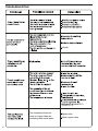
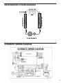
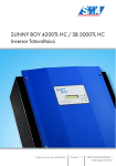
1
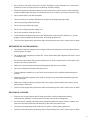
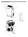
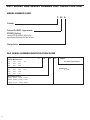
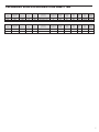
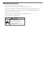
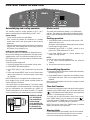
Service Manual
Model:
Portable Air Conditioner
PORT-ServMan (04-09)
P09A
P09B
P012A
P012B
TECHNICAL SUPPORT
CONTACT INFORMATION
FRIEDRICH AIR CONDITIONING CO.
Post Office Box 1540 · San Antonio, Texas 78295-1540
4200 N. Pan Am Expressway · San Antonio, Texas 78218-5212
(210) 357-4400 · FAX (210) 357-4490
www.friedrich.com
Printed in the U.S.A.
Table Of Contents
Important Safety Information ....................................................................................................................2-4
Introduction ..................................................................................................................................................4
Unit Introduction ..........................................................................................................................................5
Unit Model and Serial Number Identification ...............................................................................................6
Technical Specifications ..............................................................................................................................7
Precautions for use .....................................................................................................................................8
Control Panel Operation ..............................................................................................................................9
Remote Control Operation .........................................................................................................................10
Window Adapter Kit Installation .............................................................................................................11-12
Condensation Handling ..............................................................................................................................13
Maintenance and Service ...........................................................................................................................14
Troubleshooting ..........................................................................................................................................15
Refrigeration System Diagram ....................................................................................................................16
Wiring Diagrams .........................................................................................................................................17
Warranty .....................................................................................................................................................18
1
IMPORTANT SAFETY INFORMATION
The information contained in this manual is intended for use by a qualified service technician who is familiar
with the safety procedures required for installation and repair, and who is equipped with the proper tools and
test instruments required to service this product.
Installation or repairs made by unqualified persons can result in subjecting the unqualified person making
such repairs as well as the persons being served by the equipment to hazards resulting in injury or electrical
shock which can be serious or even fatal.
Safety warnings have been placed throughout this manual to alert you to potential hazards that may be
encountered. If you install or perform service on equipment, it is your responsibility to read and obey these
warnings to guard against any bodily injury or property damage which may result to you or others.
Your safety and the safety of others are very important.
We have provided many important safety messages in this manual and on your appliance. Always read
and obey all safety messages.
This is a safety Alert symbol.
This symbol alerts you to potential hazards that can kill or hurt you and others.
All safety messages will follow the safety alert symbol with the word “WARNING”
or “CAUTION”. These words mean:
WARNING
You can be killed or seriously injured if you do not follow instructions.
CAUTION
You can receive minor or moderate injury if you do not follow instructions.
All safety messages will tell you what the potential hazard is, tell you how to reduce the chance of injury,
and tell you what will happen if the instructions are not followed.
NOTICE
A message to alert you of potential property damage will have the
word “NOTICE”. Potential property damage can occur if instructions
are not followed.
PERSONAL INJURY OR DEATH HAZARDS
ELECTRICAL HAZARDS:
2
•
Unplug and/or disconnect all electrical power to the unit before performing inspections,
maintenance, or service.
•
Make sure to follow proper lockout/tag out procedures.
•
Always work in the company of a qualified assistant if possible.
•
Capacitors, even when disconnected from the electrical power source, retain an electrical charge
potential capable of causing electric shock or electrocution.
•
Handle, discharge, and test capacitors according to safe, established, standards, and approved
procedures.
•
Extreme care, proper judgment, and safety procedures must be exercised if it becomes necessary
to test or troubleshoot equipment with the power on to the unit.
•
Do not spray or pour water on the return air grille, discharge air grille, evaporator coil, control panel,
and sleeve on the room side of the air conditioning unit while cleaning.
•
Electrical component malfunction caused by water could result in electric shock or other electrically
unsafe conditions when the power is restored and the unit is turned on, even after the exterior is dry.
•
Never operate the A/C unit with wet hands.
•
Use air conditioner on a single dedicated circuit within the specified amperage rating.
•
Use on a properly grounded outlet only.
•
Do not remove ground prong of plug.
•
Do not cut or modify the power supply cord.
•
Do not use extension cords with the unit.
•
Follow all safety precautions and use proper and adequate protective safety aids such as: gloves,
goggles, clothing, adequately insulated tools, and testing equipment etc.
•
Failure to follow proper safety procedures and/or these warnings can result in serious injury or death.
REFRIGERATION SYSTEM HAZARDS:
•
Use approved standard refrigerant recovering procedures and equipment to relieve pressure before
opening system for repair.
•
Do not allow liquid refrigerant to contact skin. Direct contact with liquid refrigerant can result in minor
to moderate injury.
•
Be extremely careful when using an oxy-acetylene torch. Direct contact with the torch’s flame or hot
surfaces can cause serious burns.
•
Make sure to protect personal and surrounding property with fire proof materials.
•
Have a fire extinguisher at hand while using a torch.
•
Provide adequate ventilation to vent off toxic fumes, and work with a qualified assistant whenever
possible.
•
Always use a pressure regulator when using dry nitrogen to test the sealed refrigeration system for
leaks, flushing etc.
•
Make sure to follow all safety precautions and to use proper protective safety aids such as: gloves,
safety glasses, clothing etc.
•
Failure to follow proper safety procedures and/or these warnings can result in serious injury or death.
MECHANICAL HAZARDS:
•
Extreme care, proper judgment and all safety procedures must be followed when testing,
troubleshooting, handling, or working around unit with moving and/or rotating parts.
•
Be careful when, handling and working around exposed edges and corners of sleeve, chassis, and
other unit components especially the sharp fins of the indoor and outdoor coils.
•
Use proper and adequate protective aids such as: gloves, clothing, safety glasses etc.
•
Failure to follow proper safety procedures and/or these warnings can result in serious injury or death.
3
PROPERTY DAMAGE HAZARDS
FIRE DAMAGE HAZARDS:
•
Read the Installation/Operation Manual for this air conditioning unit prior to operating.
•
Use air conditioner on a single dedicated circuit within the specified amperage rating.
•
Connect to a properly grounded outlet only.
•
Do not remove ground prong of plug.
•
Do not cut or modify the power supply cord.
•
Do not use extension cords with the unit.
•
Failure to follow these instructions can result in fire and minor to serious property damage.
WATER DAMAGE HAZARDS:
•
Improper installation maintenance, or servicing of the air conditioner unit, or not following the above
Safety Warnings can result in water damage to personal items or property such.
•
Insure that the unit has a drain hose properly connected. (Drain hose is optional, see page13)
•
Do not drill holes in the bottom of the drain pan or the underside of the unit.
•
Failure to follow these instructions can result in damage to the unit and/or minor to serious property
damage.
INTRODUCTION
This service manual is designed to be used in conjunction with the installation manuals provided with each unit.
This service manual was written to assist the professional HVAC service technician to quickly and accurately
diagnose and repair any malfunctions of this product.
This manual, therefore, will deal with all subjects in a general nature. (i.e. all text will pertain to all models).
Regarding the Portable Air Conditioner
This Portable Air Conditioner is designed to provide a quick and easy cooling solution for areas that either do not have
air conditioning or areas that the current system cannot maintain at a comfortable level.
This unit is also great as a back-up system in case the primary cooling system should fail.
Other means of conditioning should be employed when the indoor temperature is either below 17°C (63°F) or above
35°C (95°F) .
This unit is designed with human comfort in mind.
IMPORTANT: It will be necessary for you to accurately identify the unit you are
servicing, so you can be certain of a proper diagnosis and repair.
(See Unit Identification.)
4
unit INTRODUCTION
1.
Control panel
2. Air outlet
3.
Signal receptor
4.
Handle
5.
Caster
6.
Air outlet hose
7.
Air filter
8.
Air intake hose
9.
1/2" water outlet drain
10.
Power supply cord
5
Unit MODEL AND SERIAL Number Unit Identification
MODEL NUMBER CODE
P 09 A
Portable
2nd and 3rd DIGIT - Approximate
BTU/HR (Cooling)
Heating BTU/Hr capacity listed in the
Specification/Performance Data Section
Design Series
RAC SERIAL NUMBER IDENTIFICATION GUIDE
Serial Number
Decade Manufactured
L=0
C=3
F=6
A=1
D=4
G=7
B=2
E=5
H=8
Year Manufactured
A=1
D=4
G=7
B=2
E=5
H=8
C=3
F=6
J=9
Month Manufactured
A=Jan D=Apr G=Jul
L
G
K 00001
J=9
K=0
Product Line
R = RAC
K=Oct
B=Feb E=May H=Aug L=Nov
C=Mar F=Jun J=Sept M=Dec
6
H
Production Run Number
TECHNICAL SPECIFICATIONS P09A AND P12A
Model
P09A
P12A
Model
P09B
P12B
Watts
Dimensions
(W” x H” x D”)
Dehumidification
(Pints/Hour)
Indoor Air
Circulation
(CFM)
Refrigerant
Charge)
(R-22)
Locked
Rotor
Amps
Net
Weight
(lbs.)
Circuit
Rating
Plug Face
(NEMA#)
8
10.5
923
1280
19.5” x 33.6” x 15.5”
19.5” x 33.6” x 15.5”
4.2
4.2
212
235
18
24.7
40.5
40.5
80
86
125V/15A
125V/15A
5-15P
5-15P
Voltage / Hz
Amps
Watts
Dimensions
(W” x H” x D”)
Dehumidification
(Pints/Hour)
Indoor Air
Circulation
(CFM)
Refrigerant
Charge)
(410 A)
Locked
Rotor
Amps
Net
Weight
(lbs.)
Circuit
Rating
Plug Face
(NEMA#)
115/60
115/60
10.8
11.5
1200
1300
19.25” x 33.62” x 15.55”
19.25” x 33.62” x 15.55”
4.2
4.2
224
235
21.2
24.7
50
50
77.2
81.6
125V/15A
125V/15A
5-15P
5-15P
Cooling Capacity
BTU/h
Voltage / Hz
Amps
8900
11500
115/60
115/60
Cooling Capacity
BTU/h
10000
12000
7
PRECAUTIONS FOR USE
•
Make sure the unit is installed in an accessible location.
•
Do not locate the unit in direct sunlight so as to avoid discoloration of the plastic.
•
Keep the unit 1 meter away from television sets or radios to avoid the risk of electromagnetic interference.
•
Ensure that the discharge air outlet is free from obstructions and not impeded by walls or other structures.
•
Operate the unity ONLY in the upright position.
•
When unplugging the unit, hold the power plug securely and pull it out carefully.
•
Do not use damaged or improper AC socket.
WARNING
EXPLOSION HAZARD
Do not use the unit near gas appliances, or
in the vicinity of flammable liquids.
Failure to follow this warning could result in
serious injury or death.
8
CONTROL PANEL OPERATION
Dehumidifying and cooling operation
Mode control
The operating range for cooling operation is 60°F - 90°F,
and the operating range for dehumidifying is 68°F - 88°F.
Power source
The mode control has three settings– Cool, Dehumidify
and Fan. The settings are adjusted with the Mode Control
button. A light will indicate which setting is currently being
used.
• The AC socket must be firm and reliable.
• Don’t connect the portable air conditioner to a multiple
socket outlet which is also being used for other electrical
appliances.
• Insert the AC power plug securely into the AC socket before
using the unit, when it beeps after two seconds, press ON/
OFF button, the unit begins to run.
LCDI power cord information
All Friedrich portable air conditioners are shipped from the
factory with a Leakage Current Detection Interrupter (LCDI)
equipped power cord. The LCDI device meets the UL and
NEC requirements for cord connected air conditioners effective August 2004.
To test your power supply cord:
1. Plug power supply cord into a grounded 3 prong outlet.
2. Press RESET (See drawing below).
3. Press TEST (listen for click; Reset button trips and pops
out).
4. Press and release RESET (listen for click; Reset button
latches and remains on). The power supply cord is ready
for operation.
NOTE: LCDI device is not intended to be used as a switch.
Once plugged in the unit will operate normally without the
need to reset the LCDI device.
TEST
RESET
If the device fails to trip when tested or if the power supply
cord is damaged it must be replaced with a new supply cord
from the manufacturer. We recommend you contact our
Technical Assistance Line at (800) 541-6645. To expedite
service, please have your model and serial number available.
Test Button
Reset Button
WARNING: NEVER
CUT OR REMOVE
THE GROUNDING
PRONG FROM
PLUG. NEVER USE
EXTENSION CORDS
TO OPERATE AN
AIR CONDITIONER.
Cooling operation
1. Press MODE button to choose the cooling mode, LCD
window will show “cool”.
During the cooling operation, always place the air exhaust
hose through an open window.
2. Repeatedly press TEMP + or TEMP - button to set a
proper room TEMP. between 60°F - 90°F.
3. Press FAN SPEED button to choose between low,
medium and high speeds.
NOTE:
In order to improve the cooling efficiency:
a) If your room is directly exposed to the sun, draw the
curtains.
b) Do not place near other heat source.
Dehumidifying Operation
1. Keep the windows and the doors closed to aid in effectively
dehumidifying the room.
2. Press MODE button to choose the dehumidifying mode,
LCD window will show “DRY”, the fan speed cannot be
adjusted.
When used as dehumidifier only it is not necessary to install
the exhaust hose.
Time Set Function
To set the time to start the machine, with the unit off (but power
supplied), press TIMER button, the LCD window will show
“
”, continually press the TIMER button, set the preferred
start time. The setting range is 1-24 hours.
To set the time to stop the machine, with the unit running,
press TIMER button, the LCD window will show “
”,
continually press the TIMER button ,set the preferred time to
stop the machine. The setting range is 1-24 hours
NOTE: During timer mode if the TIMER button is pressed
again it will cancel the timer operation.
Warning Light
Condensed water may accumulate in the unit. If the internal
tank becomes full, the Warning Light will come on and the
unit will not operate until the unit has been drained.
9
REMOTE CONTROL
Air Conditioner Remote Control
The functions work the same as your air conditioner’s touch controls.
All key function can be accessed from the remote control.
Power Control
LCD Display
On/Off
Time/Temperature Set Control
Fan Speed Control
: HIGH
: MED
:LOW
•
•
•
On / Off Timer Control
In running mode:
Auto switch off
In standby mode:
Auto switch on
Press the " " or the " "
button to adjust the time setting
for 1 hour interval.
•
Used for adjusting the timer and
temperature
The default display on control
panel is room temperature.
When the " " or the " "
button is pressed in cool mode,
the set temperature is displayed
and may be adjusted. After 15
seconds the display will revert
back to room temperature.
Timer setting is available from
1-24 hours by pressing the
button " " on " ".
Mode Control
Farenheit/Celsius Button
Notes:
- Do not drop the remote control.
- Do not place the remote control in a
location exposed to direct sunlight.
- The remote control should be placed
about 1 meter or more away from TV,
or any electrical appliances.
Press this button to change the
operation mode in the order of:
Cool
Dehumidify
Fan
Battery replacement: Remove the cover on the back of the remote control and insert the batteries with the (+) and (-)
poles pointing in the proper direction.
CAUTION
Use only AAA or IEC R03 1.5V batteries.
Remove the batteries if the remote control is not used for a month or longer.
Do not attempt to recharge the supplied batteries.
All batteries should be replaced at the same time, do not mix old battery.
Do not dispose of the batteries in a fire as they may explode.
10
Windowadapter
adapterkit
kit
Window
WINDOW ADAPTER KIT INSTALLATION
Window adapter
adapter kitkit
Window
Window
adapter
kit
An installation parts kit is packed with your unit in a separate
An installation parts kit is packed with your unit in a separate
An
installation
parts
kit
is packed
with your
unit
in aunit
separate
carton.
Before
the
that
your
came
carton.
Beforeyou
youdiscard
discard
thepackaging
packaging
that
your
unit
came
carton.
Before
you
discard
the
packaging
that
your
unit
came
in,
please
locate
the
carton
that
contains
these
parts
and
in, please locate the carton that contains these parts
and
in,
please
locate
the
carton
that contains these parts and
ensure
that
parts
arepresent.
present.
ensure
that
allallparts
are
ensure that all parts are present.
Window
panel Attaches
toopening
window to
opening
to
• Window panel
- Attaches
to window
allow air
Window panel Attaches
window opening
toair
allow airtoexchange
for system
exchange for system air transfer.
allow
air exchange for system air
transfer.
transfer.
•Window
Windowpanel
panel
extensions
Extends
window
panel
to fit
extensions Extends window
panel
to fit
windows
of various
dimensions.
Window
panel
extensions
Extends
window
panel
to fit
windows
of various
dimensions.
of various dimensions.
• Tube adapters
- Connectwindows
air exchange
tubes totubes
window
Tube adapters
Connect
Air exchange
to
exchange tubes to
windowAir
panel.
panel. Tube adapters Connect
window panel.
Screwsare 12
screws are
for the
• Screws - 12 screws
included
for included
assembling
window
adapter
Screws
12assembling
screws
arethe
included
window adapter
kit. Some
screws
may
befor
partially
kit. Some screws
may be
partially
assembling
the
window
adapter
assembled onto window panel.
assembled
ontomay
window
panel.
kit.
Some screws
be partially
assembled onto
window the
panel.
• Air exchange
tubes
Exchanges
air
between
unit
Air exchange tubes Exchanges air between the unit
andAir
outdoors.
and outdoors.
exchange tubes Exchanges
air between the unit
and outdoors.
Minimum window extension
26"
Maximum window extension
46"
Minimum hose extension
20"
Maximum hose extension
60"
Window panel extensions
Window panel extensions
Window panel
Window panel
Screws
Screws
Tube Adapters
Tube Adapters
Air Exchange Tubes
Air Exchange Tubes
Instructions for assembling the window adapter kit
Instructions
assembling
theback
window
adapter
kit
1. Insert tubefor
adapters
through the
of the window
panel.
Back of
window
panel
Back of
window panel
1. 2.
Insert
tube
adapters
through
thefour
backscrews
of thethrough
windowthe
panel.
Secure
each
tube adapter
with
front
of
the
window
panel.
2. Secure each tube adapter with four screws through the
front
of window
the window
3.
Insert
panelpanel.
extensions into window panel. Lightly
tighten
the
screws
the window
to hold
theLightly
3. Insert window panel in
extensions
intopanel
window
panel.
extensions
in
place.
tighten the screws in the window panel to hold the
extensions in place.
Tube Adapters
Tube Adapters
Window Panel
Extension
Window Panel
Extension
Window Panel
Extension screws
Window Panel
Extension screws
Window Panel
Window Panel
4
4
11
led and
operly in
quired
Fan
to fit
w
r you to
tion
window
B)
cally as
so be
nel to
urely
w attach
rouble
attach
dapter kit.
the air
kit.
er.
tube
he hole
until the
ff.
re, etc.)
proper
it.
ube 12
or
Installing the window adapter kit
Note: The window adapter kit must be installed and
connected for the air conditioner to work properly in Cool
mode. The window adapter kit is not required when using
the unit in Dehumidify or Fan modes.
Window installation
Your window adapter kit has been designed to fit most
standard vertical and horizontal window applications.
However, it may be necessary for you to modify some
aspects of the installation procedures for certain types of
windows.
7
1. Open window.
A
B
2. Place window panel with extensions into window frame
and adjust to width of window.
Window adapter kit may be installed vertically as well as
horizontally. This installation may also be used for crank
style windows.
3. Tighten the four screws on the window panel to secure
the window panel extensions.
4. Close window.
5. The window adapter kit should now fit securely within the
window frame and you can now attach the air exchange
tubes.CIf you are having trouble attaching
the air exchange
D
tubes, you may attach the tubes prior to installing the
window adapter kit.
Attaching the air exchange tubes to the air
conditioner
1. Attach the tubes to the window adapter kit.
2. Attach the other end to the air conditioner.
To attach air exchange tubes: push tube onto tube adapter
and twist until the tab is in place in the hole on the tube.
Vertical
installation
E air
To remove
exchange
tubes: twist the end until the tab is
clear of the hole in the tube and pull off.
Do not attach the tubes if using the unit in dehumidify
mode.
Maintain a clear distance (from walls, furniture, etc.)
of at least 10 inches around the unit to allow proper
air circulation and prevent damage to the unit.
Important: Do not over-stretch the exhaust tube or
8
9
make
any unnecessary bends
in it.
nd
u.
de
ks
e
annual inspection is the
consumer’s responsibility.
CONDENSATION HANDLING
Your ZoneAire® Portable Air Conditioner is designed to
evaporate the condensation removed from the interior space
through the exhaust hose. Under certain conditions it is
possible that the unit will not evaporate 100% of the removed
moisture.
The unit is designed with a built-in reservoir to accumulate
excess condensate and help dispose of it.
CAUTION
Internal Water Level
1. Under any mode if the water level is in the “low” area the
unit will function normally.
Draining Water
The water can be drained from the unit by removing the base
stopper and letting the water drain by gravity.
1. When the WATER FULL lamp is on unplug the unit
and move the unit to a suitable location for draining the
condensation.
2. Using the gravity drain method, ensure that the base
stopper is located above a suitable area for draining the
condensate and remove the stopper. Re-install the stopper
once all water has drained.
3. Return the unit to the original location and restore power
Failure to keep air filter clean will
result
and duct
connections.
2. If the water level is in the “normal” area the unit will
The WATER FULL indicator should be off and the unit will
continue
to function
normally
while internally evaporating
in poor
air
circulation.
DO NOT4. operate
return to normal operating mode.
the condensate.
without
filter.
This
can
render
the
unit
3. If the unit cannot evaporate all of the condensate internally,
the
tank may become full. If the tank becomes full, the unit
Permanent Drainage
inoperative.
will turn off, and the Water Full light will illuminate.
For permanent and continuous drainage, a 1/2" hose may be
attached to the unit and led down a drain.
he
ne
en
IEC R03
+
1.5V
CAUTION:
AAA 1.5V
AAA
-
Drain Valve
IEC R03
13
MAINTENANCE / SERVICE
WARNING
RISK OF ELECTRIC SHOCK
Unplug and/or disconnect all electrical power
to the unit before performing inspections,
maintenances or service.
Failure to do so could result in electric shock,
serious injury or death.
Cleaning the air filter
If the air filter is blocked with a lot of dust, the air flow volume
will be reduced. Clean the filter once every two weeks.
Open and clean the air filter:
1. Pull the filter out as shown in the drawing.
2. Take out the air filter from the filter cover.
3. Wash the air filter by immersing it gently into warm (about
40°C or 104°F) water with a neutral detergent or vacuum
the filter clean.
4. Rinse the filter and dry it thoroughly in a shaded place.
5. Install the air filter back to its original place.
Cleaning the air conditioner
Clean the surface of the unit with a damp cloth, then dry using a duster or similar.
Do not use chemical solvent (like benzene or alcohol) to
clean the surface of the unit. If you do so, the surface may
be scratched, damaged or even cause the case to become
deformed.
Prior to operating seasons
1. Check to ensure that the air inlets and outlets of the unit
are not blocked.
2. Make sure that air filter is properly in place before operating the machine. If the machine is operated with air filter
removed, dust and foreign objects will result in faulty performance of the air conditioner.
14
Preparation for storage
1. Turn off the air conditioner, disconnect the power.
2. Perform proper maintenance to the air filter and other
parts.
3. Open the base stopper to drain out all of the water from
the base. Operating the unit in fan only mode for 12 hours
will help ensure there is no moisture within the unit.
4. Cover the unit to prevent dust or filth from entering the unit.
Drain valve
TROUBLESHOOTING
15
TROUBLESHOOTING
Unblock
(below72 F)
The compressor bolts are
loose or copper tubes are
contacting other metal parts
16
Tighten bolts
Adjust copper tubes
REFRIGERATOR SYSTEM DIAGRAM
SCHEMATIC WIRING DIAGRAM
17
Friedrich Air Conditioning Company
P.O. Box 1540
San Antonio, TX 78295
210.357.4400
www.friedrich.com
PORTABLE AIR CONDITIONERS
LIMITED WARRANTY
FIRST YEAR
ANY PART: If any part supplied by FRIEDRICH fails because of a defect in workmanship or material within twelve months from
date of original purchase, FRIEDRICH will repair the product at no charge, provided the product is transported to a Friedrich
Authorized Service Center for repair. ALL transportation charges are the sole responsibility of the owner. This remedy is expressly
agreed to be the exclusive remedy within twelve months from the date of the original purchase.
SECOND THROUGH FIFTH YEAR
SEALED REFRIGERANT SYSTEM: If the Sealed Refrigeration System (defined for this purpose as the compressor, condenser
coil, evaporator coil, reversing valve, check valve, capillary, filter drier, and all interconnecting tubing) supplied by FRIEDRICH in
your Room Air Conditioner fails because of a defect in workmanship or material within sixty months from date of purchase,
FRIEDRICH will pay a labor allowance and parts necessary to repair the Sealed Refrigeration System; PROVIDED FRIEDRICH will
not pay the cost of diagnosis of the problem, removal, freight charges, and transportation of the air conditioner to and from the
Service Agency, and the reinstallation charges associated with repair of the Sealed Refrigeration System. All such cost will be the
sole responsibility of the owner. This remedy is expressly agreed to be the exclusive remedy within sixty months from the date of the
original purchase.
APPLICABILITY AND LIMITATIONS: This warranty is applicable only to units retained within the Fifty States of the U.S.A., District
of Columbia, and Canada. This warranty is not applicable to:
1.
2.
3.
Air filters or fuses.
Products on which the model and serial numbers have been removed.
Products which have defects or damage which results from improper installation, wiring, electrical current
characteristics, or maintenance; or caused by accident, misuse or abuse, fire, flood, alterations and/or misapplication
of the product and/or units installed in a corrosive atmosphere, default or delay in performance caused by war,
government restrictions or restraints, strikes, material shortages beyond the control of FRIEDRICH, or acts of God.
OBTAINING WARRANTY PERFORMANCE: Service will be provided by the FRIEDRICH Authorized Dealer or Service
Organization in your area. They are listed in the Yellow Pages. If assistance is required in obtaining warranty performance, write
to: Room Air Conditioner Service Manager, Friedrich Air Conditioning Co., P.O. Box 1540, San Antonio, TX 78295-1540.
LIMITATIONS:
THIS WARRANTY IS GIVEN IN LIEU OF ALL OTHER WARRANTIES. Anything in the warranty
notwithstanding, ANY IMPLIED WARRANTIES OF FITNESS FOR PARTICULAR PURPOSE AND/OR MERCHANTABILITY
SHALL BE LIMITED TO THE DURATION OF THIS EXPRESS WARRANTY. MANUFACTURER EXPRESSLY DISCLAIMS AND
EXCLUDES ANY LIABILITY FOR CONSEQUENTIAL OR INCIDENTAL DAMAGE FOR BREACH OF ANY EXPRESSED OR
IMPLIED WARRANTY.
NOTE: Some states do not allow limitations on how long an implied warranty lasts, or do not allow the limitation or exclusion of
consequential or incidental damages, so the foregoing exclusions and limitations may not apply to you.
OTHER: This warranty gives you specific legal rights, and you may also have other rights which vary from state to state.
PROOF OF PURCHASE: Owner must provide proof of purchase in order to receive any warranty related services.
All service calls for explaining the operation of this product will be the sole responsibility of the consumer.
All warranty service must be provided by an Authorized FRIEDRICH Service Agency, unless authorized by FRIEDRICH prior to
repairs being made.
(7-06)
18
20
TECHNICAL SUPPORT
CONTACT INFORMATION
FRIEDRICH AIR CONDITIONING CO.
Post Office Box 1540 · San Antonio, Texas 78295-1540
4200 N. Pan Am Expressway · San Antonio, Texas 78218-5212
(210) 357-4400 · FAX (210) 357-4490
www.friedrich.com
Printed in the U.S.A.
FRIEDRICH AIR CONDITIONING CO.
Post Office Box 1540 · San Antonio, Texas 78295-1540
4200 N. Pan Am Expressway · San Antonio, Texas 78218-5212
(210) 357-4400 · FAX (210) 357-4490
www.friedrich.com
Printed in the U.S.A.
PORT-ServMan (04-09)