1
GE Healthcare
Voluson™ E8/E8 Expert
Basic User Manual
English (English)
H48691CF
Revision 2
GE imagination at work
BT13 EC200
© 2013 by General Electric
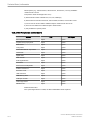
Revision History
Revision
i-ii
Date
Revision MV
June 2012
Revision 1
August 2012
Revision 2
January 2013
Voluson™ E8/E8 Expert Basic User Manual
H48691CF Revision 2
Table of Contents
Chapter 1 – General
About this User Manual - - - - - - - - - - - - - - - - - - - - - - - - - - - - - - - - - - - - - - - - - - - - - - 1-2
Contacting GE Healthcare Ultrasound - - - - - - - - - - - - - - - - - - - - - - - - - - - - - - - - - - - - 1-3
Chapter 2 – Safety and Maintenance
Symbols and Labels - - - - - - - - - - - - - - - - - - - - - - - - - - - - - - - - - - - - - - - - - - - - - - - - 2-2
Remarks for Safe Use - - - - - - - - - - - - - - - - - - - - - - - - - - - - - - - - - - - - - - - - - - - - - - - 2-7
System Safety and Maintenance - - - - - - - - - - - - - - - - - - - - - - - - - - - - - - - - - - - - - - - 2-7
Probe Safety and Maintenance - - - - - - - - - - - - - - - - - - - - - - - - - - - - - - - - - - - - - - - - 2-14
Biopsy Safety and Maintenance - - - - - - - - - - - - - - - - - - - - - - - - - - - - - - - - - - - - - - - 2-22
Manufacturer Responsibility - - - - - - - - - - - - - - - - - - - - - - - - - - - - - - - - - - - - - - - - - - 2-24
Service Documents - - - - - - - - - - - - - - - - - - - - - - - - - - - - - - - - - - - - - - - - - - - - - - - - 2-24
Bioeffects and Safety of Ultrasound Scans - - - - - - - - - - - - - - - - - - - - - - - - - - - - - - - 2-24
Disposal - - - - - - - - - - - - - - - - - - - - - - - - - - - - - - - - - - - - - - - - - - - - - - - - - - - - - - - - 2-27
Guidance and manufacturer´s declaration - - - - - - - - - - - - - - - - - - - - - - - - - - - - - - - - 2-28
Network disclosure - - - - - - - - - - - - - - - - - - - - - - - - - - - - - - - - - - - - - - - - - - - - - - - - 2-31
Chapter 3 – Description of the System
Product Description - - - - - - - - - - - - - - - - - - - - - - - - - - - - - - - - - - - - - - - - - - - - - - - - - 3-2
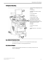
System Assembly - - - - - - - - - - - - - - - - - - - - - - - - - - - - - - - - - - - - - - - - - - - - - - - - - - 3-3
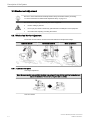
Mechanical Adjustment - - - - - - - - - - - - - - - - - - - - - - - - - - - - - - - - - - - - - - - - - - - - - - 3-4
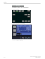
Concept of Operation - - - - - - - - - - - - - - - - - - - - - - - - - - - - - - - - - - - - - - - - - - - - - - - 3-7
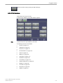
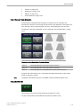
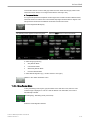
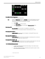
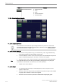
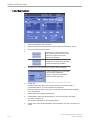
Layout of Menus - - - - - - - - - - - - - - - - - - - - - - - - - - - - - - - - - - - - - - - - - - - - - - - - - - - 3-7
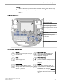
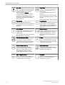
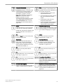
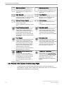
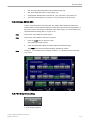
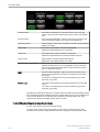
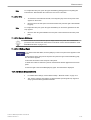
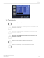
Button description - - - - - - - - - - - - - - - - - - - - - - - - - - - - - - - - - - - - - - - - - - - - - - - - - 3-11
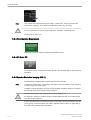
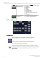
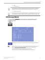
Electronic User Manual (EUM) - - - - - - - - - - - - - - - - - - - - - - - - - - - - - - - - - - - - - - - - 3-16
Chapter 4 – Operating the System
General Remarks - - - - - - - - - - - - - - - - - - - - - - - - - - - - - - - - - - - - - - - - - - - - - - - - - - 4-2
System Start-Up - - - - - - - - - - - - - - - - - - - - - - - - - - - - - - - - - - - - - - - - - - - - - - - - - - - 4-2
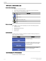
Probe connection and selection - - - - - - - - - - - - - - - - - - - - - - - - - - - - - - - - - - - - - - - - 4-4
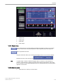
Entering Patient Data - - - - - - - - - - - - - - - - - - - - - - - - - - - - - - - - - - - - - - - - - - - - - - - 4-7
Image Annotation - - - - - - - - - - - - - - - - - - - - - - - - - - - - - - - - - - - - - - - - - - - - - - - - - 4-26
Scan Assistant - - - - - - - - - - - - - - - - - - - - - - - - - - - - - - - - - - - - - - - - - - - - - - - - - - - 4-33
Chapter 5 – Probes and Biopsies
Probes - - - - - - - - - - - - - - - - - - - - - - - - - - - - - - - - - - - - - - - - - - - - - - - - - - - - - - - - - - 5-2
Biopsies - - - - - - - - - - - - - - - - - - - - - - - - - - - - - - - - - - - - - - - - - - - - - - - - - - - - - - - - - 5-8
Overview of all probes and biopsies - - - - - - - - - - - - - - - - - - - - - - - - - - - - - - - - - - - - 5-13
Chapter 6 – 2D Mode
2D Main Menu - - - - - - - - - - - - - - - - - - - - - - - - - - - - - - - - - - - - - - - - - - - - - - - - - - - - 6-2
2D Operation - - - - - - - - - - - - - - - - - - - - - - - - - - - - - - - - - - - - - - - - - - - - - - - - - - - - - 6-3
Cine Mode - - - - - - - - - - - - - - - - - - - - - - - - - - - - - - - - - - - - - - - - - - - - - - - - - - - - - - 6-15
2D Sub Menu - - - - - - - - - - - - - - - - - - - - - - - - - - - - - - - - - - - - - - - - - - - - - - - - - - - - 6-19
Gray Map - - - - - - - - - - - - - - - - - - - - - - - - - - - - - - - - - - - - - - - - - - - - - - - - - - - - - - - 6-21
B-Flow - - - - - - - - - - - - - - - - - - - - - - - - - - - - - - - - - - - - - - - - - - - - - - - - - - - - - - - - - 6-25
XTD-View (Extended View) - - - - - - - - - - - - - - - - - - - - - - - - - - - - - - - - - - - - - - - - - - 6-27
Contrast Imaging - - - - - - - - - - - - - - - - - - - - - - - - - - - - - - - - - - - - - - - - - - - - - - - - - - 6-35
Chapter 7 – M Mode
M Main Menu - - - - - - - - - - - - - - - - - - - - - - - - - - - - - - - - - - - - - - - - - - - - - - - - - - - - - 7-2
M Operation - - - - - - - - - - - - - - - - - - - - - - - - - - - - - - - - - - - - - - - - - - - - - - - - - - - - - - 7-3
Voluson™ E8/E8 Expert Basic User Manual
H48691CF Revision 2
i-iii
Table of Contents
M Sub Menu - - - - - - - - - - - - - - - - - - - - - - - - - - - - - - - - - - - - - - - - - - - - - - - - - - - - - - 7-6
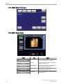
MCFM Mode (M Color Flow Mode) - - - - - - - - - - - - - - - - - - - - - - - - - - - - - - - - - - - - - - 7-7
MTD Mode (M Tissue Doppler Mode) - - - - - - - - - - - - - - - - - - - - - - - - - - - - - - - - - - - 7-10
MHD Mode (M High Density Mode) - - - - - - - - - - - - - - - - - - - - - - - - - - - - - - - - - - - - - 7-13
STIC with M-Mode - - - - - - - - - - - - - - - - - - - - - - - - - - - - - - - - - - - - - - - - - - - - - - - - - 7-15
Anatomical M-Mode (AMM) - - - - - - - - - - - - - - - - - - - - - - - - - - - - - - - - - - - - - - - - - - 7-15
Chapter 8 – Doppler Modes
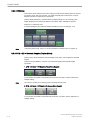
Pulsed Wave Doppler Mode (PW Mode) - - - - - - - - - - - - - - - - - - - - - - - - - - - - - - - - - - 8-2
Continuous Wave Doppler Mode (CW Mode) - - - - - - - - - - - - - - - - - - - - - - - - - - - - - - - 8-7
Color Flow Mode (CFM) - - - - - - - - - - - - - - - - - - - - - - - - - - - - - - - - - - - - - - - - - - - - - 8-10
Power Doppler Mode (PD Mode) - - - - - - - - - - - - - - - - - - - - - - - - - - - - - - - - - - - - - - 8-15
HD-Flow™Mode (Bi-directional Angio Mode) - - - - - - - - - - - - - - - - - - - - - - - - - - - - - - 8-19
Tissue Doppler Mode (TD Mode) - - - - - - - - - - - - - - - - - - - - - - - - - - - - - - - - - - - - - - 8-23
Doppler Mode Functions and Filters - - - - - - - - - - - - - - - - - - - - - - - - - - - - - - - - - - - - 8-27
Chapter 9 – Elastography Mode
GUI elements - - - - - - - - - - - - - - - - - - - - - - - - - - - - - - - - - - - - - - - - - - - - - - - - - - - - Elastography Main Menu - - - - - - - - - - - - - - - - - - - - - - - - - - - - - - - - - - - - - - - - - - - - Elastography Sub Menu - - - - - - - - - - - - - - - - - - - - - - - - - - - - - - - - - - - - - - - - - - - - - Elastography Analysis - - - - - - - - - - - - - - - - - - - - - - - - - - - - - - - - - - - - - - - - - - - - - - -
9-2
9-3
9-4
9-5
Chapter 10 – Volume Mode
Volume Acquisition with Volume Probes - - - - - - - - - - - - - - - - - - - - - - - - - - - - - - - - - 10-2
Volume Acquisition: Static 3D Sectional Planes - - - - - - - - - - - - - - - - - - - - - - - - - - - 10-13
Sub Menus - - - - - - - - - - - - - - - - - - - - - - - - - - - - - - - - - - - - - - - - - - - - - - - - - - - - - 10-42
Volume Acquisition: Static 3D Render - - - - - - - - - - - - - - - - - - - - - - - - - - - - - - - - - - 10-49
Real Time 4D Acquisition - - - - - - - - - - - - - - - - - - - - - - - - - - - - - - - - - - - - - - - - - - - 10-79
Sono Render Start - - - - - - - - - - - - - - - - - - - - - - - - - - - - - - - - - - - - - - - - - - - - - - - - 10-92
Volume Cine - - - - - - - - - - - - - - - - - - - - - - - - - - - - - - - - - - - - - - - - - - - - - - - - - - - - 10-92
Volume Contrast Imaging: (VCI A-Plane) - - - - - - - - - - - - - - - - - - - - - - - - - - - - - - - - 10-96
VCI-Omniview - - - - - - - - - - - - - - - - - - - - - - - - - - - - - - - - - - - - - - - - - - - - - - - - - - - 10-98
STIC (Spatio-Temporal Image Correlation) - - - - - - - - - - - - - - - - - - - - - - - - - - - - - 10-102
Real Time 4D Biopsy - - - - - - - - - - - - - - - - - - - - - - - - - - - - - - - - - - - - - - - - - - - - - 10-109
VOCAL II - - - - - - - - - - - - - - - - - - - - - - - - - - - - - - - - - - - - - - - - - - - - - - - - - - - - - 10-111
SonoAVC™ follicle - - - - - - - - - - - - - - - - - - - - - - - - - - - - - - - - - - - - - - - - - - - - - - 10-130
SonoAVC™ general - - - - - - - - - - - - - - - - - - - - - - - - - - - - - - - - - - - - - - - - - - - - - - 10-136
SonoVCAD™ heart - Volume Computer Aided Display - - - - - - - - - - - - - - - - - - - - - 10-139
SonoVCAD™ labor - - - - - - - - - - - - - - - - - - - - - - - - - - - - - - - - - - - - - - - - - - - - - - 10-144
HDlive™ Mode - - - - - - - - - - - - - - - - - - - - - - - - - - - - - - - - - - - - - - - - - - - - - - - - - 10-149
System messages - - - - - - - - - - - - - - - - - - - - - - - - - - - - - - - - - - - - - - - - - - - - - - - 10-151
Chapter 11 – Measurements
Generic Measurements - - - - - - - - - - - - - - - - - - - - - - - - - - - - - - - - - - - - - - - - - - - - - 11-2
Chapter 12 – Calculations and Patient Worksheets (Reports)
Calculation Packages - - - - - - - - - - - - - - - - - - - - - - - - - - - - - - - - - - - - - - - - - - - - - - 12-2
Basic Calculation Functionality - - - - - - - - - - - - - - - - - - - - - - - - - - - - - - - - - - - - - - - - 12-2
Basic Patient Worksheet Functions - - - - - - - - - - - - - - - - - - - - - - - - - - - - - - - - - - - - - 12-5
Abdomen Calculations - - - - - - - - - - - - - - - - - - - - - - - - - - - - - - - - - - - - - - - - - - - - - 12-10
Small Parts Calculations - - - - - - - - - - - - - - - - - - - - - - - - - - - - - - - - - - - - - - - - - - - 12-18
Obstetric Calculations - - - - - - - - - - - - - - - - - - - - - - - - - - - - - - - - - - - - - - - - - - - - - 12-20
Cardiac Calculations - - - - - - - - - - - - - - - - - - - - - - - - - - - - - - - - - - - - - - - - - - - - - - 12-39
Urology Calculations - - - - - - - - - - - - - - - - - - - - - - - - - - - - - - - - - - - - - - - - - - - - - - 12-54
Vascular Calculations - - - - - - - - - - - - - - - - - - - - - - - - - - - - - - - - - - - - - - - - - - - - - 12-56
i-iv
Voluson™ E8/E8 Expert Basic User Manual
H48691CF Revision 2
Table of Contents
Gynecology Calculations - - - - - - - - - - - - - - - - - - - - - - - - - - - - - - - - - - - - - - - - - - Pediatric Calculations - - - - - - - - - - - - - - - - - - - - - - - - - - - - - - - - - - - - - - - - - - - - Neurology Calculations - - - - - - - - - - - - - - - - - - - - - - - - - - - - - - - - - - - - - - - - - - - MSK Calculations - - - - - - - - - - - - - - - - - - - - - - - - - - - - - - - - - - - - - - - - - - - - - - - -
12-59
12-62
12-64
12-67
Chapter 13 – Archive
Current Patient Dialog - - - - - - - - - - - - - - - - - - - - - - - - - - - - - - - - - - - - - - - - - - - - - - 13-3
Clipboard - - - - - - - - - - - - - - - - - - - - - - - - - - - - - - - - - - - - - - - - - - - - - - - - - - - - - - - 13-6
Patient Archive - - - - - - - - - - - - - - - - - - - - - - - - - - - - - - - - - - - - - - - - - - - - - - - - - - 13-11
Image History - - - - - - - - - - - - - - - - - - - - - - - - - - - - - - - - - - - - - - - - - - - - - - - - - - - 13-34
Exam Review - - - - - - - - - - - - - - - - - - - - - - - - - - - - - - - - - - - - - - - - - - - - - - - - - - - 13-35
Selecting Exams - - - - - - - - - - - - - - - - - - - - - - - - - - - - - - - - - - - - - - - - - - - - - - - - - 13-43
Settings - - - - - - - - - - - - - - - - - - - - - - - - - - - - - - - - - - - - - - - - - - - - - - - - - - - - - - - 13-45
Chapter 14 – Utilities and System Setup
Utilities - - - - - - - - - - - - - - - - - - - - - - - - - - - - - - - - - - - - - - - - - - - - - - - - - - - - - - - - - 14-2
System Setup - - - - - - - - - - - - - - - - - - - - - - - - - - - - - - - - - - - - - - - - - - - - - - - - - - - 14-11
Chapter 15 – Programmable Keys
Where to program the keys - - - - - - - - - - - - - - - - - - - - - - - - - - - - - - - - - - - - - - - - - P-keys - - - - - - - - - - - - - - - - - - - - - - - - - - - - - - - - - - - - - - - - - - - - - - - - - - - - - - - - Start Exam Button - - - - - - - - - - - - - - - - - - - - - - - - - - - - - - - - - - - - - - - - - - - - - - - - End Exam Button - - - - - - - - - - - - - - - - - - - - - - - - - - - - - - - - - - - - - - - - - - - - - - - - -
15-2
15-3
15-8
15-9
Chapter 16 – Measure Setup
To Invoke the Setup Procedure - - - - - - - - - - - - - - - - - - - - - - - - - - - - - - - - - - - - - - - 16-2
To Exit from the Measure Setup - - - - - - - - - - - - - - - - - - - - - - - - - - - - - - - - - - - - - - - 16-3
The Measure Setup Pages - - - - - - - - - - - - - - - - - - - - - - - - - - - - - - - - - - - - - - - - - - - 16-3
Chapter 17 – Connections
How to Connect Auxiliary Devices Safely - - - - - - - - - - - - - - - - - - - - - - - - - - - - - - - - - 17-2
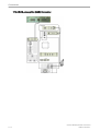
Connection between Internal I/O and External I/O - - - - - - - - - - - - - - - - - - - - - - - - - - 17-5
Recorder type - - - - - - - - - - - - - - - - - - - - - - - - - - - - - - - - - - - - - - - - - - - - - - - - - - - - 17-8
ECG Preamplifier - - - - - - - - - - - - - - - - - - - - - - - - - - - - - - - - - - - - - - - - - - - - - - - - 17-12
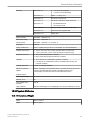
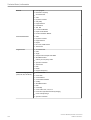
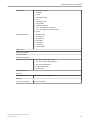
Chapter 18 – Technical Data / Information
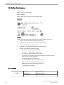
Safety Conformance - - - - - - - - - - - - - - - - - - - - - - - - - - - - - - - - - - - - - - - - - - - - - - - 18-2
Physical Attributes - - - - - - - - - - - - - - - - - - - - - - - - - - - - - - - - - - - - - - - - - - - - - - - - - 18-3
System overview - - - - - - - - - - - - - - - - - - - - - - - - - - - - - - - - - - - - - - - - - - - - - - - - - - 18-5
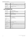
Screen Formats - - - - - - - - - - - - - - - - - - - - - - - - - - - - - - - - - - - - - - - - - - - - - - - - - - 18-6
Display Modes - - - - - - - - - - - - - - - - - - - - - - - - - - - - - - - - - - - - - - - - - - - - - - - - - - - 18-7
Display Annotation - - - - - - - - - - - - - - - - - - - - - - - - - - - - - - - - - - - - - - - - - - - - - - - - 18-7
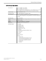
System Standard Features - - - - - - - - - - - - - - - - - - - - - - - - - - - - - - - - - - - - - - - - - - 18-10
System Options - - - - - - - - - - - - - - - - - - - - - - - - - - - - - - - - - - - - - - - - - - - - - - - - - - 18-11
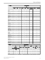
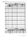
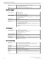
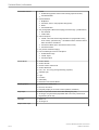
System Parameters - - - - - - - - - - - - - - - - - - - - - - - - - - - - - - - - - - - - - - - - - - - - - - - 18-13
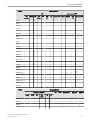
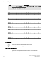
Scanning Parameters - - - - - - - - - - - - - - - - - - - - - - - - - - - - - - - - - - - - - - - - - - - - - 18-17
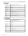
Generic Measurements and Measurements/Calculations - - - - - - - - - - - - - - - - - - - - 18-26
External Inputs and Outputs - - - - - - - - - - - - - - - - - - - - - - - - - - - - - - - - - - - - - - - - - 18-33
Chapter 19 – Glossary- Abbreviations
Voluson™ E8/E8 Expert Basic User Manual
H48691CF Revision 2
i-v
This page was intentionally left blank.
i-vi
Voluson™ E8/E8 Expert Basic User Manual
H48691CF Revision 2
Chapter 1
General
This chapter consists of information concerning indications for use and contact information.
Voluson™ E8/E8 Expert Basic User Manual
H48691CF Revision 2
1-1
General
The Voluson™ E8/E8 Expert is a professional diagnostic Ultrasound System which transmits
Ultrasound waves into body tissues and forms images from the information contained within
the received echoes.
The Voluson™ E8/E8 Expert is an Active Diagnostic Medical Product belonging to Class IIa
according to the MDD 93/42/EEC regulation for use on human patients.
The Voluson™ E8/E8 Expert is developed and produced by GE Healthcare Austria GmbH &
Co OG. For more Information, please contact:
GE Healthcare Austria GmbH & Co OG
Tiefenbach 15
Telephone:
+43-7682-3800-0
4871 Zipf
Fax.:
+43-7682-3800-47
Austria
Internet:
http://www.gehealthcare.com
Dear Valuable Customer,
We herewith would like to inform you that the American Institute of Ultrasound in Medicine
(AIUM) advocates the responsible use of diagnostic ultrasound. The AIUM strongly
discourages the non-medical use of ultrasound for psychosocial or entertainment purposes.
The use of either two-dimensional (2D) or three-dimensional (3D) ultrasound to only view the
fetus, obtain a picture of the fetus or determine the fetal gender without a medical indication is
inappropriate and contrary to responsible medical practice. Although the general use of
ultrasound for medical diagnosis is considered safe, ultrasound energy has the potential to
produce biological effects. Ultrasound bioeffects may result from scanning for a prolonged
period, inappropriate use of color or pulsed Doppler ultrasound without a medical indication, or
excessive thermal or mechanical index settings (American Institute of Ultrasound in Medicine:
Keepsake Fetal Imaging; 2005).Thus ultrasound should be used in a prudent manner to
provide medical benefit to the patient.
1.1 About this User Manual
•
•
•
•
•
Read and understand all instructions in the Basic User Manual before attempting to use
the Voluson™ E8/E8 Expert .
This Manual has to be used in connection with the Voluson™ E8/E8 Expert .
Keep this User Manual with the equipment at all times.
All information contained in the Voluson™ E8/E8 Expert User Manual is relevant.
Periodically review the procedures for operation and safety precautions.
Please note that orders are based on the individually agreed specifications and may not
contain all features listed in this manual.
It might be possible that some probes, options or features are NOT available in some
countries!
The screen graphics and illustrations in this manual are for illustrative purposes only and may
be different from what is displayed on the screen or device.
1-2
Voluson™ E8/E8 Expert Basic User Manual
H48691CF Revision 2
General
All references to standards / regulations and their revisions are valid for the time of publication
of the user manual.
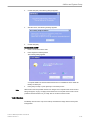
1.2 Contacting GE Healthcare Ultrasound
For additional information or assistance, please contact your local distributor or the appropriate
support resource listed on the following pages:
INTERNET
http://www.gehealthcare.com
http://www.gehealthcare.com/usen/ultrasound/products/
probe_care.html
Clinical Questions
For information in the United States, Canada, Mexico and parts of the
Caribbean, call the Customer Answer Center
Phone: (1) 800-682-5327 or (1) 262-524-5698
In other locations, contact your local Applications, Sales or Service
Representative.
Service Questions
For service in the United States, call GE CARES
Phone: (1) 800-437-1171
For service for compact products in the United States, call Phone: (1)
877-800-6776
In other locations, contact your local Service Representative.
Information Request
To request the latest GE Accessories catalog or equipment brochures
in the United States, call the Response Center
Phone: (1) 800-643-6439
In other locations, contact your local Applications, Sales or Service
Representative.
Placing an Order
To order accessories, supplies or service parts in the United States,
call the GE Healthcare Technologies Contact Center
Phone: (1) 800-558-5102
In other locations, contact your local Applications, Sales or Service
Representative.
ARGENTINA
GEME S.A.
Miranda 5237
Buenos Aires - 1407
Phone: (1) 639-1619
Fax: (1) 567-2678
ASIA PACIFIC
JAPAN
GE Healthcare Asia Pacific
4-7-127, Asahigaoka
Hino-shi, Tokyo
191-8503 Japan
Tel: +81 42 585 5111
Voluson™ E8/E8 Expert Basic User Manual
H48691CF Revision 2
1-3
General
AUSTRALIA
NEW ZEALAND
GE Healthcare Australia & New Zealand
Building 4B, 21 South St
Rydalmere NSW 2116
Australia
Tel: 1300 722 229
8 Tangihua Street
Auckland 1010
New Zealand
Tel: 0800 434 325
AUSTRIA
General Electric Austria GmbH Filiale GE Healthcare Technologies
EURO PLAZA, Gebäude E
Wienerbergstrasse 41
A-1120 Vienna
Phone: (+43) 1 97272 0
Fax: (+43) 1 97272 2222
BELGIUM &
GE Medical Systems Ultrasound Eagle Building
LUXENMBURG
Kouterveldstraat 20
1831 DIEGEM
Phone: (+32) 2 719 7204
Fax: (+32) 2 719 7205
BRAZIL
Equipamentos Médicos Ltda
Av. Das Nações Unida, 8501
3º andar parte - Pinheiros
São Paulo SP - CEP: 05425-070
C.N.P.J.: 02.022.569/0001-83
Phone: 3067-8493
Fax: (011) 3067-8280
CANADA
GE Healthcare
Ultrasound Service Engineering
9900 Innovation Drive
Wauwatosa, WI 53226
Phone: (1) 800 668-0732
Customer Answer Center Phone: (1) 262-524-5698
CHINA
GE Healthcare - Asia
No. 1, Yongchang North Road
Beijing Economic & Technology Development Area
Beijing 100176, China
Phone: (8610) 5806 8888
Fax: (8610) 6787 1162
CZECH REPUBLIC
GE Medical Systems Ultrasound
Vyskocilova 1422/1a
140 28 Praha
1-4
Voluson™ E8/E8 Expert Basic User Manual
H48691CF Revision 2
General
DENMARK
GE Medical Systems Ultrasound
Park Alle 295
2605 Brøndby
Phone: (+45) 43 295 400
Fax: (+45) 43 295 399
ESTONIA &
GE Medical Systems
FINLAND
Kuortaneenkatu 2, 000510 Helsinki
P.O.Box 330, 00031 GE Finland
Phone: (+358) 10 39 48 220
Fax: (+358) 10 39 48 221
FRANCE
GE Medical Systems Ultrasound and Primary Care Diagnostics
F-78457 Velizy
Fax: (+33) 13 44 95 202
General Imaging: Phone: (+33) 13 449 52 43
Cardiology: Phone: (+33) 13 449 52 31
GERMANY
GE Healthcare GmbH
Beethovenstrasse 239
42655 Solingen
Phone: (+49) 212-28 02-0
Fax: (+49) 212-28 02 28
GREECE
GE Healthcare
8-10 Sorou Str. Marousi
Athens 15125 Hellas
Phone: (+30) 210 8930600
Fax: (+30) 210 9625931
HUNGARY
GE Hungary Zrt. Ultrasound Division
Akron u. 2
Budaors 2040 Hungary
Phone: (+36) 23 410 314
Fax: (+36) 23 410 390
INDIA
Wipro GE Healthcare Pvt Ltd
No. 4, Kadugodi Industrial Area
Bangalore, 560067
Phone: +(91) 1-800-425-8025
ITALY
GE Medical Systems Italia spa
Via Galeno, 36
20126 Milano
Phone: (+39) 02 2600 1111
Fax: (+39) 02 2600 1599
KOREA
Seoul, Korea
Phone: (+82) 2 6201 3114
LUXEMBOURG
Voluson™ E8/E8 Expert Basic User Manual
H48691CF Revision 2
Phone: 0800 2603 toll free
1-5
General
MEXICO
GE Sistemas Medicos de Mexico S.A. de C.V.
Rio Lerma #302, 1º y 2º Pisos
Colonia Cuauhtemoc
06500-Mexico, D.F.
Phone: (5) 228-9600
Fax: (5) 211-4631
NETHERLANDS
GE Healthcare
De Wel 18 B, 3871 MV Hoevelaken
PO Box 22, 3870 CA Hoevelaken
Phone: (+31) 33 254 1290
Fax: (+31) 33 254 1292
NORTHERN
IRELAND
GE Healthcare
Victoria Business Park
9, Westbank Road, Belfast BT3 9JL
Phone: (+44) 28 90229900
NORWAY
GE Medical Systems Ultrasound
Tåsenveien 71, 0873 Oslo
Phone: (+47) 2202 0800
Strandpromenaden 45, P.O. Box 141, 3191 Horten
Phone: (+47) 33 02 11 16
POLAND
GE Medical Systems Polska
Sp. z o.o., ul. Wołoska 9
02-583 Warszawa, Poland
Phone: (+48) 22 330 83 00
Fax: (+48) 22 330 83 83
PORTUGAL
General Electric Portuguesa
SA. Avenida do Forte, n° 4
Fraccao F, 2795-502 Carnaxide
Phone: (+351) 21 425 1309
Fax: (+351) 21 425 1343
REPUBLIC OF
IRELAND
GE Healthcare
Unit F4, Centrepoint Business Park
Oak Drive, Dublin 22
Phone: (+353) 1 4605500
RUSSIA
GE Healthcare
Krasnopresnenskaya nab., 18, bld A, 10th floor
123317 Moscow, Russia
Phone: (+7) 4957 396931
Fax:(+7) 4957 396932
SINGAPORE
GE Healthcare Singapure
1 Maritime Square #13-012
HarbourFront Centre
Singapore 099253
Tel: +65 6291 8528
1-6
Voluson™ E8/E8 Expert Basic User Manual
H48691CF Revision 2
General
SPAIN
GE Healthcare Espana
C/ Gobelas 35-37
28023 Madrid
Phone: (+34) 91 663 2500
Fax: (+34) 91 663 2501
SWEDEN
GE Medical Systems Ultrasound
PO Box 314
17175 Stockholm
Phone: (+46) 8 559 50010
SWITZERLAND
GE Medical Systems Ab
Europastrasse 31
8152 Glattbrugg
Phone: (+41) 1 809 92 92
Fax: (+41) 1 809 92 22
TURKEY
GE Healthcare Türkiye
Istanbul Office TEL: +90 212 398 07 00
Levent Ofis FAKS: +90 212 284 67 00
Esentepe Mah. Harman Sok.
No:8 Sisli-Istanbul
Ankara Office TEL: +90 312 289 77 00
Mustafa Kemal Mah. FAKS: +90 312 289 78 02
2158.Sok No:9
Çankaya-Ankara
United Arab Emirates GE Healthcare Holding
(U.A.E.)
Dubai Internet City, Building No. 18
P.O. Box #11549, Dubai U.A.E.
Phone: +971 4 4296161
Phone: +971 4 4296101
Fax: +971 4 4296201
UNITED KINGDOM
GE Medical Systems Ultrasound
71 Great North Road
Hatfield, Hertfordshire, AL9 5EN
Phone: (+44) 1707 263570
Fax: (+44) 1707 260065
USA
GE Healthcare
Ultrasound Service Engineering
9900 Innovation Drive
Wauwatosa, WI 53226
Phone: (1) 800-437-1171
Fax: (1) 414-721-3865
Voluson™ E8/E8 Expert Basic User Manual
H48691CF Revision 2
1-7
General
This page was intentionally left blank.
1-8
Voluson™ E8/E8 Expert Basic User Manual
H48691CF Revision 2
Chapter 2
Safety and Maintenance
Describes the safety and maintenance information pertinent for operating this ultrasound system
and the probes.
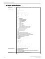
Sections in this chapter:
•
•
•
•
•
•
•
•
•
•
•
'Symbols and Labels' on page 2-2
'Remarks for Safe Use' on page 2-7
'System Safety and Maintenance' on page 2-7
'Probe Safety and Maintenance' on page 2-14
'Biopsy Safety and Maintenance' on page 2-22
'Manufacturer Responsibility' on page 2-24
'Service Documents' on page 2-24
'Bioeffects and Safety of Ultrasound Scans' on page 2-24
'Disposal' on page 2-27
'Guidance and manufacturer´s declaration' on page 2-28
'Network disclosure' on page 2-31
Voluson™ E8/E8 Expert Basic User Manual
H48691CF Revision 2
2-1
Safety and Maintenance
The Voluson™ E8/E8 Expert scanner system has been designed for utmost safety for patient
and user. Read the following chapters thoroughly before you start working with the machine!
The manufacturer guarantees safety and reliability of the system only when all the following
cautions and warnings are observed.
INTENDED USE
This system is intended for use by a qualified physician for ultrasound evaluation in the
following clinical applications:
Image Acquisition for diagnostic purposes including measurements on acquired image.
Clinical applications:
•
•
•
•
Fetal/Obstetrics
Abdominal/GYN (including infertility
monitoring of follicle development)
Pediatric
Small Organ (breast, testes, thyroid,
etc.)
•
•
•
Peripheral Vascular
•
Transvaginal and Transrectal
Cardiac (fetal cardio)
Patient population:
•
•
•
•
•
Operator profile:
•
Age: all ages (incl.
embryos and fetuses)
Location: worldwide
Sex: male and female
•
Weight: all weight
categories
Height: no height
limitations
Qualified and trained
physicians or
sonographers with at least
basic ultrasound
knowledge.
The operator must have
read and understood the
user manual.
Musculo-skeletal Conventional and
Superficial
CONTRAINDICATIONS
The Voluson™ E8/E8 Expert system is not intended for:
•
•
ophthalmic use or any use causing the acoustic beam to pass through the eye.
intra-operative use that is defined as introducing probe into a surgical incision or burr
hole
ESSENTIAL PERFORMANCE OF THE ULTRASOUND SYSTEM
•
•
•
•
Acquisition of ultrasound images
Display of ultrasound images on main display
Measurement on ultrasound images
System must remain in a safe condition acc. IEC60601
2.1 Symbols and Labels
Description of all symbols and labels used on the system and in the basic user manual.
2.1.1 Warning labels used in the Basic User Manual
Note
Warning labels in the user manual have to be read and observed before proceeding!
Notice:
Describes important information that has to be read before proceeding.
2-2
Voluson™ E8/E8 Expert Basic User Manual
H48691CF Revision 2
Safety and Maintenance
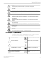
Caution:
Describes general precautions necessary to protect health and equipment.
Bio Hazard:
Describes precautions necessary to prevent the risk of disease transmission or infections.
Electric Hazard:
Describes precautions necessary to prevent the risk of injury through electric hazards.
Explosion Hazard:
Describes precautions necessary to prevent the risk of injury through explosion hazards!
Moving Hazard:
Describes precautions necessary to prevent the risk of injury through moving or tipping
hazards!
Mechanical Hazard:
Describes precautions necessary to prevent the risk of injury through mechanical hazards!
Radiation Hazard:
Laser radiation
Orientation:
Lists all major sections in the chapters, for orientation purposes.
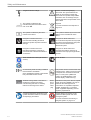
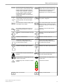
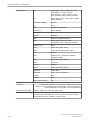
2.1.2 Description of symbols and labels
Some symbols used with electrical medical equipment have been accepted as standard by
IEC. They serve for marking connections, accessories, and as warnings.
Main power switch ON
Insulated patient application part (Type
BF)
Main power switch OFF
Protective earth (ground) connection
System stand-by switch
ECG symbol
Potential equilibrium connection
Defibrillation-proof CF applied part
Protection against the effects of
immersion in water (probes)
No protection against ingress of water
(system)
Voluson™ E8/E8 Expert Basic User Manual
H48691CF Revision 2
2-3
Safety and Maintenance
Dangerous electric voltage.
Caution, consult accompanying
documents. This symbol advises the
reader to consult the accompanying
documents for important safety-related
information such as warnings and precautions that cannot be presented on the
device itself.
This symbol is followed by the
manufacturing date of the device in the
form YYYY-MM
Disposal:
This symbol is followed by the serial
number of the device.
This symbol is followed by the name and
address of the manufacturer of the
device.
Pictogram on Probe Care Card:
Pictogram on Probe Care Card:
Use care when handling ultrasound
probes and protect the probe head from
damage.
Do not immerse the probe into any liquid
beyond the level specified for that probe.
Refer to the user manual of the
ultrasound system.
Pictogram on Probe Care Card:
Pictogram on Probe Care Card:
Describes precautions necessary to
prevent the risk of disease transmission
or infections.
Describes precautions necessary to
prevent the risk of injury through electric
hazards.
NRTL Classification Label (old and new
version)
GOST-R Label
CE Conformity mark according to Medical
Device Directive 93/42/EEC
This product consists of devices that may
contain mercury, which must be recycled
or disposed of in accordance with local,
state, or country laws. (Within this
system, the backlight lamps in the
monitor display, contain mercury.)
For more information see 'Disposal' on
page 2-27.
0123: Identification number of the notified
body TÜV SÜD Product Service
All labels looking similar to the label on
the left are a marker used during
manufacturing and have no meaning
relevant to the usage of the device.
Consult accompanying documents. This
symbol advises the reader to consult the
accompanying documents.
Green
dot on
power
cable
plug
Indicates that the power cable is hospital
grade. Grounding reliability can only be
achieved when the equipment is
connected to an equivalent receptacle
marked “Hospital only” or “Hospital
grade”. Applicable depending on local
regulatory requirements.
Tipping danger. Do not lean on the
system and take special care when
moving the system.
For more information see 'Moving or
lifting the System' on page 2-10.
2-4
Voluson™ E8/E8 Expert Basic User Manual
H48691CF Revision 2
Safety and Maintenance
This text indicates the voltages that the
device is built for. Please note that either
the first voltage range OR the second
voltage range is applicable – depending
on your country’s voltage. This device
uses alternating current. For actual
voltage range used for your device see
symbol below.
This indicates the electrical frequency
that the device is built for. Please note
that either the first frequency OR the
second frequency is applicable –
depending on your country’s frequency.
The voltage shown in this area, is the
voltage actually required for the device
(country specific), see also description
above.
This indicates the approximate weight of
the system in kilograms.
This indicates the maximum rated power
consumption of the system.
This symbol indicates that in the United
States of America, federal law restricts
this device to sale by or on the order of a
physician.
This symbol indicates that the device is
equipped with hardware for using CW
Doppler.
Indicates a connector that allows for
output only.
Indicates a connector that allows for input
only.
Indicates a connector that allows for inand output.
Indicates a USB connector.
Indicates a network connector.
Connect the monitor cable to this
connector (One cable used for power,
one cable used for signal).
Connect the monitor cable to this
connector (One cable used for power,
one cable used for signal).
Indicates a DVI/VGA output connector.
Indicates an S-Video output connector.
Push this button to eject a CD/DVD from
the drive.
These symbols indicate that the DVD
drive can read and write DVDs.
Use this button to change brightness and
contrast of the monitor.
Use these buttons to navigate in the
monitor menu.
Indicates the power connection for the lift
cylinder.
Lock/Unlock of wheels.
Batch or lot number
Catalog or model number.
Voluson™ E8/E8 Expert Basic User Manual
H48691CF Revision 2
2-5
Safety and Maintenance
Do not reuse! This symbol indicates that
the item/device is for single use only.
Dedicated USB port on optional Digital
Video Recorder (DVR): record to USB
stick
These symbols indicate that at least one of the six hazardous substances of the China RoHS
Labelling Standard is above the RoHS limitation. The number inside the circle is referred to as
the Environmental Friendly Use Period (EFUP). It indicates the number of years that the
product, under normal use, will remain harmless to health of humans or the environment.
EFUP = 10 for Short Use Products
EFUP = 20 for Medium Use Products
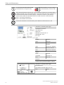
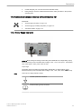
Product was refurbished / remanufactured by GE Healthcare Austria GmbH & Co OG
Information on internal power supply:
Assembled in xxxxxxxxx
S/N: RGM xxxxx
RGM xxxxx
RGM P/N: xxxxxxxxx Rev. xx
RGM MODEL: xxxxx
D/C xxxxx
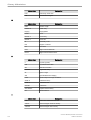
Input
Jumper
Used for
100V
100V/11A
115V
110V/10A, 115V/10A,
120V/9A
125V
127V/8.7A, 130V/8.5A
225V
220V/5A, 230V/5A
250V
240V/4.5A, 250V/4.5A
Output
34.5V
max 23A
115V/230V
max 3A/1.5A
230V
max 0.9A
50-60 Hz
Continous max. powerConsumption: 1000VA
Information on internal power supply:
Manufactured for:
GE Healthcare Austria GmbH & Co OG
RTN
2-6
RoHS
Voluson™ E8/E8 Expert Basic User Manual
H48691CF Revision 2
Safety and Maintenance
2.2 Remarks for Safe Use
•
•
•
•
•
•
•
•
•
•
•
•
•
•
•
•
Get acquainted with the transducers and the ultrasound system: read the user manual
thoroughly!
Misinterpretation of an Ultrasound Image can lead to false diagnosis.
Follow all safety instructions as well as the clinically adopted precautions and measures
for hygiene. Observe all warning labels.
Any ultrasound transducers - irrespective of system and design - are sensitive to shock
and shall be treated with care. Pay attention to cracks, which may allow conductive fluids
to leak in.
Do not squeeze, kink, bend or twist probe cables and protect them against mechanical
damage.
The probes must not be exposed to mechanical shock (e.g., by dropping). Any damage
caused in this will void the warranty!
Have the scanner system and the transducers regularly checked (for faulty cables,
housing, etc.) by authorized personnel!
Damage to transducer or cable may lead to a safety hazard, therefore have them
repaired immediately!
Before plugging in or unplugging a transducer, activate the “FREEZE” mode!
A specialist familiar with the handling and use of the system shall perform installation
and first switch-on and check-up of the system.
For safety reason, avoid handling fluids in the vicinity of the system. Fluids leaking into
the disk drive can damage the drive. Never remove the storage shelf above the probe
connectors; it helps to protect the system from fluids.
The user manual must always be with the scanner system. It is the user’s duty to ensure
this!
Only probes conforming to type BF requirements may be used with the Voluson™ E8/E8
Expert. See the probe’s label. In case of doubt ask authorized service personnel.
Do not install software on the system, that has not been released by GE Healthcare
Austria GmbH & Co OG, as this may lead to erroneous data transfer and thereby
decrease system performance.
The Voluson™ E8/E8 Expert system has been tested for EMC and is compliant with EN
55011 group 1 class A (CISPR 11 amendment 1) and IEC 60601-1-2.
Main power quality should be that of a typical commercial and/or hospital environment. If
the user requires continued operation during power main interruption, it is recommended
that the system be powered from an uninterruptible power source (UPS).
2.3 System Safety and Maintenance
Federal law restricts this device to sale by or on the order of a physician!
Caution! This machine should be used in compliance with the law. Some jurisdictions restrict
certain uses such as gender determination.
Voluson™ E8/E8 Expert Basic User Manual
H48691CF Revision 2
2-7
Safety and Maintenance
Caution:
The quality of the image used for diagnosis is essential:
•
•
Changing the display settings can affect the image quality and compromise the
diagnostic quality. The user is responsible to use adequate display settings for achieving
appropriate image quality. If in doubt, only the image as displayed on the Voluson™
ultrasound system with default display settings is to be used for diagnostic purposes.
Do not diagnose based on print-outs.
Caution:
Features that facilitate measurements (e.g. SonoAVC™ follicle, Vocal, SonoNT,...) must be
used with extreme care. Such measurements are a suggestion of the system. If in doubt verify
the measurement results with manual measurement methods. The user is responsible for the
diagnostic interpretation of measurements.
Caution
The system provides calculations (e.g estimated fetal weight) and charts based on published
scientific literature. The selection of the appropriate chart and clinical interpretation of
calculations and charts are the sole responsibility of the user. The user must consider
contraindications for the use of a calculation or chart as described in the scientific literature.
The diagnosis, decision for further examinations and medical treatment must be performed by
qualified personnel following good clinical practice.
2.3.1 Instructions for Use
This equipment has been tested and found to comply with the limits for medical devices in IEC
60601-1-2. These limits are designed to provide reasonable protection against harmful
interference in a typical medical installation. This equipment generates, uses and can radiate
radio frequency energy and, if not installed and used in accordance with the instructions, may
cause harmful interference to other devices in the vicinity. However, there is no guarantee that
interference will not occur in a particular installation. If this equipment does cause harmful
interference to other devices, which can be determined by turning the equipment off and on,
the user is encouraged to try to correct the interference by one or more of the following
measures:
•
•
•
Increase the distance between equipment.
•
Consult the manufacturer or field service technician for help.
Reorient or relocate the device.
Connect the equipment to an outlet on a circuit different from that to which the other
device(s) are connected.
2.3.2 Environmental Conditions for Operation
For more information see 'Details' on page 18-2.
Ultrasound systems are highly sensitive medical instruments that can easily be damaged by
improper handling. Use care when handling and protect from damage also when not in use.
DO NOT use a damaged or defective ultrasound system. Failure to follow these precautions
can result in serious injury and equipment damage.
2-8
Voluson™ E8/E8 Expert Basic User Manual
H48691CF Revision 2
Safety and Maintenance
This equipment is not to be used during transportation (e.g. ambulance cars, aircraft).
This equipment must not be used in oxygen enriched atmosphere or in the presence of
inflammable gases (e.g. anesthetic gases).
The use of the system outside the described conditions or intended use, and disregarding
safety related information is considered as abnormal use. The manufacturer is not liable for
damage caused by abnormal use of the device!
Use for diagnostic purposes only!
Do not operate the system in the vicinity of a heat source, of strong electric or magnetic fields
(close to a transformer), or near instruments generating high-frequency signals, such as HF
surgery. These can affect the ultrasound images adversely.
In the event the equipment has been brought from a cold environment (stock room, airfreight)
into a warm room, allow several hours for temperature balance and passing of condensation
humidity before switching on for the first time.
Do not cover the ventilation holes of the Voluson™ E8/E8 Expert!
The user is responsible for the safety of all persons in the vicinity of the ultrasound system
including the patient(s).
Thermal Safety:
Maintaining a safe thermal environment for the patient has been a design priority at GE
Healthcare. The operating temperature of the ultrasound probe stays below 43˚C if used as
intended.
For more information see 'Details' on page 18-2.
Using the system in sterile environment:
•
•
•
•
The ultrasound console cannot be sterilized. The use of protective console covers is not
validated by the manufacturer GE Healthcare Austria GmbH&Co OG.
It is in the responsibility of the user to use appropriate protective console covers from 3rd
parties or have a non-sterile person operate the system.
Always follow the hygienic guidelines established by the institution where the ultrasound
system is used.
The ultrasound probes cannot be sterilized. It is in the responsibility of the user to use
sterile probe sheaths as described in the Basic User Manual.
2.3.2.1 Electric Installation
The system must be exclusively installed in medically used rooms. The equipment conforms
with regulations for electrical safety (IEC 60601) and safety class IIa according to the MDD
93/42/EEC regulation for use on human patients. Ultrasound probes are rated Type BF. Local
Voluson™ E8/E8 Expert Basic User Manual
H48691CF Revision 2
2-9
Safety and Maintenance
safety regulations may require an additional connection between the potential equilibrium bolt
and the building’s grounding system.
Before switching on the first time, the local main voltage and frequencies have to be checked
against the values indicated on the Voluson™ E8/E8 Expert rating plate located on the rear
panel. Only authorized personnel must perform any change to the system. Unauthorized
modifications may result in hazardous situations. The minimum required house installation
must have 16A.
The system is equipped with main outlets separated by an isolation transformer for peripheral
equipment (printer, VCR/DVR). To ensure electrical safety, these instruments must never be
connected to a wall socket.
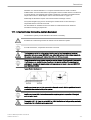
2.3.3 Moving or lifting the System
Moving the system on plains
Moving the system on inclines
The Voluson™ E8/E8 Expert weighs 130 kg or more, depending on installed peripherals, (300
lbs., or more) when ready for use.
Care must be used when moving it or replacing its parts. Failure to follow the precautions
listed could result in injury, uncontrolled motion and costly damage.
ALWAYS:
Two people are required when moving on inclines or lifting more than 16 kg (35 lbs).
•
•
Use the handle to move the system. • Be sure the pathway is clear.
Use slow, careful motions. • Do not let the system strike walls or door frames.
Always place the system on horizontal ground and engage the caster brakes. For more
information see 'Caster Brakes' on page 3-6.
Handle carefully. A drop of more than 5 cm may cause mechanical damages.
The monitor has to be secured with the monitor transport-lock when moving or transporting the
system. For more information see 'Mechanical Monitor Adjustment' on page 3-4.
2-10
Voluson™ E8/E8 Expert Basic User Manual
H48691CF Revision 2
Safety and Maintenance
Lower the console to its minimal height when moving or transporting the system.
Move the system forward or backward when going up or down inclines. Do not move the
system sideways or diagonally.
'User interface adjustment' on page 3-5
2.3.3.1 How to lift the system
1.
Remove the footrest cover on the front side of the system.
2.
Pass a strap through the openings in the metal sheet.
3.
Lift the system by the strap.
Always use a strap to lift the system. Do not grasp the metal sheet with your hands.
2.3.4 Mechanical adjustment safety
Make sure that nothing would be jammed when adjusting mechanical parts of the system.
Never put your hand or fingers between moveable parts of the system when adjusting them.
Do not put your hand between the control console and the main body when moving it to the 0
position: Danger of injury!
Do not lift the system with the front handle of the user interface.
Be gentle and careful when adjusting the monitor or locking monitor parts!
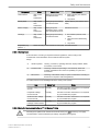
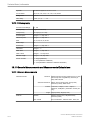
2.3.5 ECG preamplifier (MAN)
The ECG preamplifier type MAN is an option of the ultrasound scanner system used to obtain
an ECG signal to mark the systolic and end diastolic moments in M mode and Doppler
evaluations.
Voluson™ E8/E8 Expert Basic User Manual
H48691CF Revision 2
2-11
Safety and Maintenance
•
•
•
•
•
•
The ECG preamplifier MAN is not intended for ECG diagnosis. It must not be used for an
intra-operative application of the heart.
Monitor: Not for use as a cardiac monitor.
Only the patient cable supplied by GE Healthcare Austria GmbH & Co OG, and only
recommended electrodes must be used.
Take care that neither bare parts of one of the three electrodes nor the patient comes
into contact with conductive parts (e.g., metal parts of the examination bed, trolley, or
similar).
If the use of a HF surgical system with simultaneously connected ECG electrodes
becomes necessary, a large distance of ECG electrodes from the surgical field and a
perfect position of the neutral electrode of the HF surgical system must be observed
(avoiding burning risk).
If the use of a defibrillator becomes necessary, there must be no ECG adhesive
electrodes and no conductive paste between the correct positions of the defibrillator
plates (avoid current bridge; the signal input of the ECG preamplifier is defibrillator-safe).
For further details and information please review: 'ECG Preamplifier' on page 17-12
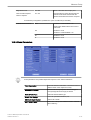
2.3.6 Cleaning and Maintenance
Have the system checked and serviced in regular intervals (once per year) by authorized
service personnel. In case of total failure first check if main voltage is present. Mentioning any
observations or failure symptoms to the service engineers is helpful.
Before cleaning the scanner switch it off. Do not use disinfection spray nor gas disinfection.
Electric parts must be protected from drip water. Keep the touch panel screen clean. Dust and
grime on the frame can cause irregular function! Check the main cable, transducer cables,
plugs and sockets on a regular basis.
No covers or panels must be removed from the system (high-voltage risk). Only GE
Healthcare authorized personnel must perform service and repairs. Attempting do-it-yourself
repairs invalidate warranty, and are an infringement to regulations and are inadmissible acc. to
IEC 60601-1. For expected lifetime of equipment and probes see Service Manual.
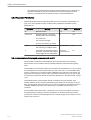
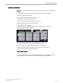
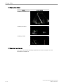
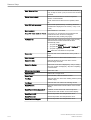
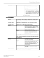
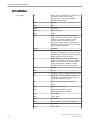
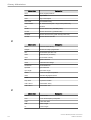
The following table provides cleaning instructions for the ultrasound device. Effective cleaning
and disinfection is not possible for parts with narrow gaps and holes (e.g. keyboard,
trackball,...). It is the responsibility of the user to decide which cleaning and disinfection
procedure is necessary to ensure a safe working environment. Electrical contacts and
connectors must not be cleaned. Do not use any other cleaning agents than listed in the table
below. Do not spray any liquid directly on the system.
Component
Probe holder
When
daily or after
each
examination
How to clean
Wipe gently with a damp,
non-abrasive cloth.
Cleaning agent
•
•
•
Probes
2-12
daily or after
each
examination
IPA solution (70% IPA, 30%
water)
Sani-Cloth Active disinfecting
wipes
Acryl des®
See Probe Care Card and 'Probe Maintenance' on page 2-18
Voluson™ E8/E8 Expert Basic User Manual
H48691CF Revision 2
Safety and Maintenance
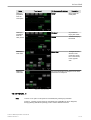
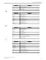
Component
When
User interface
How to clean
Cleaning agent
•
daily or after
each
examination
Wipe gently with a damp,
non-abrasive cloth.
Touch panel
daily or after
each
examination
Wipe gently with a damp,
non-abrasive cloth.
Spiritus dilutus (70% ethanol, 30%
water)
Monitor display
daily or after
each
examination
Wipe gently with
absorbent cotton or other
soft material like chamois.
Petroleum benzene
Housings
daily or after
each
examination
Wipe gently with a damp,
non-abrasive cloth.
•
•
•
•
Peripherals (e.g.
printers,...)
Spiritus dilutus (70% ethanol,
30% water)
Acryl des®
IPA solution (70% IPA, 30%
water)
Sani-Cloth Active disinfecting
wipes
Acryl des®
Clean according to the instructions of the peripheral manufacturer.
2.3.6.1 Safety Test
Scan time limits: According to respective national regulations, and according to the
manufacturer recommendations for the medical-technical system.
Range:
a)
Visual inspection: Housing, connection, operating elements, display facilities, labels,
accessories, user manual.
b)
Functional test:
Checking of functions (according to user manual), check also
modular combinations and common operability of system and
accessories.
c)
Electric test:
Checking of the electric safety of system combinations according to
EN 62353 or respective national regulations.
For safety reasons, avoid handling fluids in the vicinity of the system.
Item
Safety Test
Notes
Console Leakage Current Annually
Checks
Also after corrective maintenance or as required
by your facilities QA program.
Peripheral Leakage
Current Checks
Annually
Also after corrective maintenance or as required
by your facilities QA program.
Surface Probe Leakage
Current Checks
Annually
Also after corrective maintenance or as required
by your facilities QA program.
Endocavity Probe
Leakage Current Checks
Annually
Also after corrective maintenance or as required
by your facilities QA program.
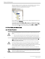
2.3.6.2 Note for the Administration of “Full Backup” Data
All settings and patient data created since last full backup are NOT backed-up! It is highly
recommended to create a full backup of settings and patient data regularly.
Voluson™ E8/E8 Expert Basic User Manual
H48691CF Revision 2
2-13
Safety and Maintenance
When the Full Backup is stored on a network drive, it may be desirable to move the data (e.g.,
for backup or maintenance). For further details review: 'Backup' on page 14-49
The directory structure of the full backup data is as follows:
Every “Full Backup” resides in a sub-folder of the main “fullbackup”-folder found at the root of
the drive. For example: Z:\fullbackup.
The sub-folders have the names fbX where X is a number (e.g., Z:\fullbackup\fb1). The data
resides within a directory structure within these sub-folders. It is possible to move the fbX subfolders, even leaving gaps in the numeration sequence. However, NO change MUST be made
to the contents of the fbX folders itself, otherwise the backup data cannot be restored!
2.4 Probe Safety and Maintenance
2.4.1 Handling Precautions
In case HF surgical equipment is used in combination with an ultrasound probe placed on the
patient, the following protective measures have to be taken to avoid the risk of burns to the
patient:
•
•
Keep a large distance between the HF surgical field and the applied ultrasound probe
Ensure that the neutral electrode of the HF surgical equipment is correctly positioned
Ultrasound probes are highly sensitive medical instruments that can easily be damaged by
improper handling. Use care when handling and protect from damage when not in use. DO
NOT use a damaged or defective probe. Failure to follow these precautions can result in
serious injury and equipment damage.
Transducer damage can result from contact with inappropriate coupling or cleaning agents.
Do not soak or saturate transducers with solutions containing alcohol, bleach, ammonium
chloride compounds, hydrogen peroxide or incompatible solutions as shown on the Care-card!
Avoid contact with solutions or coupling gels containing mineral oil or lanolin.
Inspect the probe prior to use for damage or degeneration to the housing, strain relief, lens
and seal.
If a probe has dropped on the floor or on any other hard surface, immediately disconnect the
probe from the ultrasound system. Do not use the probe any more. There is a risk of electric
shock due to damaged electrical insulation.
2-14
Voluson™ E8/E8 Expert Basic User Manual
H48691CF Revision 2
Safety and Maintenance
Note
Sporadically, silicone grease can leak in small amounts from the probes’ cable bushing. This
leakage is not a failure or harmful to the human body. Silicone grease does not contain any
hazardous substances and is only used to seal the cable bushing. In case of a leakage wipe
the grease with a cloth.
2.4.2 Watertightness
Attention: All probes labeled "IPX7" are watertight up to a minimum of 5 cm above the probe
cable strain relief. If the probe is not explicitly marked as IPX7, the probe up to a minimum of 5
cm above the probe strain relief fulfills IPX1 according to IEC60601-2-37.
'Probe Maintenance' on page 2-18
2.4.3 Electrical Shock Hazard
The probe is driven with electrical energy that can injure the patient or user if live internal parts
are contacted by conductive solution:
•
•
•
•
•
DO NOT immerse the probe into any liquid beyond the immersion level. 'Probe
Maintenance' on page 2-18 Never immerse the probe connector or probe adaptors into
any liquid.
DO NOT drop the probes or subject them to other types of mechanical shock or impact.
Degraded performance or damage such as cracks or chips in the housing may result.
Inspect the probe before and after each use for damage or degradation to the housing,
strain relief, lens, and seal. A thorough inspection should be conducted during the
cleaning process.
DO NOT kink, tightly coil, or apply excessive force on the probe cable. Insulation failure
may result.
Electrical leakage checks should be performed on a routine basis by GE Service or
qualified hospital personnel. Refer to the service manual for leakage check procedures.
2.4.4 Mechanical Hazards
A defective probe or excessive force can cause patient injury or probe damage:
•
•
•
Observe depth markings and do not apply excessive force when inserting or
manipulating intracavitary probes.
Inspect probes for sharp edges or rough surfaces that could injure sensitive tissue.
Avoid mechanical shock or impact to the transducer and do not apply excessive bending
or pulling force to the cable.
2.4.5 Cable Handling
Take the following precautions with probe cables:
•
•
•
Keep free from wheels.
Do not bend the cable acutely.
Avoid crossing cables between probes.
Voluson™ E8/E8 Expert Basic User Manual
H48691CF Revision 2
2-15
Safety and Maintenance
2.4.6 Ergonomics
Probes have been ergonomically designed to:
•
•
•
•
Handle and manipulate with ease.
Connect to the system with one hand.
Be lightweight and balanced.
Have rounded edges and smooth surfaces.
Cables have been designed to:
•
•
Connect to system with appropriate cable length.
Stand up to typical wear with cleaning and using disinfectant agents, contact with
approved gel, etc.
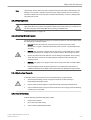
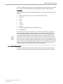
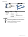
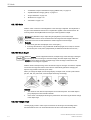
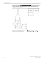
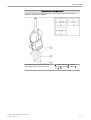
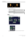
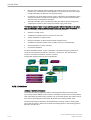
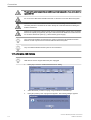
2.4.7 Preparing the Transducer
There have been reports of severe allergic reactions to medical devices containing latex
(natural rubber). Operators are advised to identify latex-sensitive patients and be prepared to
treat allergic reactions promptly. Refer to FDA Medical Alert MDA91-1.
•
•
Use a sufficient amount of coupling gel!
Take care to use only reinforced finger cots and probe sheaths, normal ones tear very
easily!
Procedure:
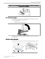
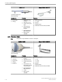
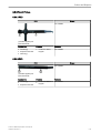
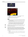
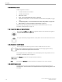
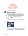
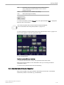
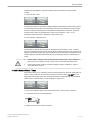
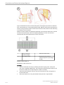
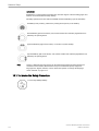
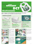
1.
Put coupling gel on the transducer tip and pull the long medical sheath (1) over the shaft.
2.
Apply a sufficient amount of coupling gel on the area of the acoustic window.
For example: Voluson™ TRANSVAGINAL TRANSDUCER RIC5-9-D
1. Medical probe-sheath
2.4.7.1 Probe Usage
For details about connecting, activating, deactivating, disconnecting, transporting and storing
the probes, refer to: 'Probe connection' on page 4-4 and 'Probe selection' on page 4-5.
2.4.7.1.1 Coupling Gels
Do not use un-recommended gels (lubricants). They may damage the probe and void the
warranty.
Applying:
2-16
Voluson™ E8/E8 Expert Basic User Manual
H48691CF Revision 2
Safety and Maintenance
In order to assure optimal transmission of energy between the patient and probe, a conductive
gel or couplant must be applied liberally to the patient where scanning will be performed.
Precautions:
Coupling gels should not contain the following ingredients, as they are known to cause probe
damage:
•
•
•
•
•
•
•
•
•
Methanol, ethanol, isopropanol, or any other alcohol-based product
Mineral oil
Iodine
Lotions
Lanolin
Aloe Vera
Olive Oil
Methyl or Ethyl Parabens (para hydroxybenzoic acid)
Dimethylsilicone
When scanning in air (Ultrasound probe is not in contact with a human body or a phantom)
most of the ultrasound energy is reflected at the lens - air surface and bounces back and
forward between that interface and the transducer ceramics. Already the smallest deviation
from the ideal geometrical shape of the reflecting interfaces can cause irregularities in the
reverberation pattern across the transducer surface. However, when the probe is coupled to
the human skin or a phantom by using coupling gel most of the ultrasound energy passes the
lens - skin interface and these small geometrical deviations will have a negligible effect on the
ultrasound signal and image quality. Therefore variations of the reverberation pattern along the
transducer cannot be used for judging image and transducer quality. The use of a tissue
mimicking phantom is strongly recommended to assess image quality.
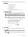
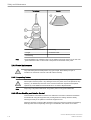
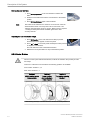
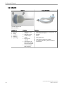
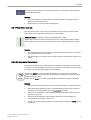
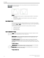
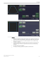
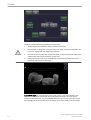
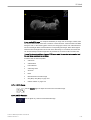
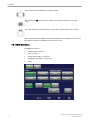
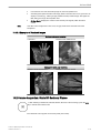
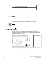
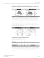
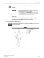
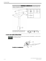
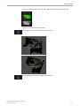
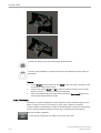
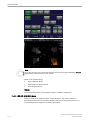
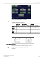
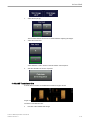
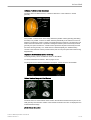
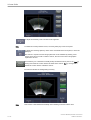
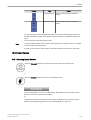
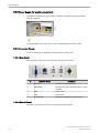
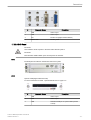
2.4.7.2 Probe Orientation
Each probe is provided with an orientation marking. This mark is used to identify the side of
the probe corresponding to the side of the image having the orientation mark on the display.
Voluson™ E8/E8 Expert Basic User Manual
H48691CF Revision 2
2-17
Safety and Maintenance
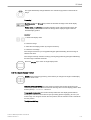
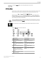
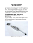
Transducer:
Monitor:
1. Mark for direction of insonation
1. Shadowing
2. Finger
2. Orientation mark
3. Shadowing
Note
The Probe RRE6-10-D orientation mark is in the middle of the probe and not on the side. The
green orientation marker on the monitor corresponds to the left side of the probe.
2.4.8 Probe Maintenance
Only authorized personnel shall perform any type of repair. Never attempt to open a
transducer or transducer connector. This will void the warranty!
2.4.8.1 Inspecting Probes
After each use, inspect the probe’s lens, cable, and casing. Look for any damage that would
allow liquid to enter the probe. If any damage is found, the probe must not be placed into any
liquid (e.g. for disinfection) and must not be used until it has been inspected and repaired/
replaced by a GE Healthcare Austria GmbH & Co OG Service Representative.
Note
Keep a log of all probe maintenance, along with a picture of any probe malfunction.
2.4.8.2 Probe Handling and Infection Control
This information is intended to increase user awareness of the risks of disease transmission
associated with using this equipment and provide guidance in making decisions directly
affecting the safety of the patient as well as the equipment user.
Diagnostic ultrasound systems utilize ultrasound energy that must be coupled to the patient by
direct physical contact. Depending on the type of examination, this contact occurs with a
2-18
Voluson™ E8/E8 Expert Basic User Manual
H48691CF Revision 2
Safety and Maintenance
variety of tissues ranging from intact skin in a routine exam to recirculating blood in a surgical
procedure.
The level of risk of infection varies greatly with the type of contact.
One of the most effective ways to prevent transmission between patients is with single use or
disposable devices. However, ultrasound transducers are complex and expensive devices that
must be reused between patients. It is very important, therefore, to minimize the risk of
disease transmission by using barriers and through proper processing between patients.
2.4.8.3 Probe Cleaning and Disinfecting Process
Adequate cleaning and disinfection is necessary to prevent disease transmission. It is the
responsibility of the user to verify and maintain the effectiveness of the infection control
procedures in use.
High-level disinfection is recommended for surface probes and is mandatory for endocavity
probes. Additional to disinfection the use of sterile, legally marketed probe sheaths for
endocavity procedures is MANDATORY.
Ultrasound probes can be disinfected using different methods. The level of disinfection is
directly related to the duration of contact with the germicide. Increased contact time produces
a higher level of disinfection.
CREUTZFELDT-JAKOB DISEASE
Neurological use on patients with this disease must be avoided. If a probe becomes
contaminated, there is no adequate disinfecting means.
Recommendation for cleaning and disinfection of ultrasound probes:
1.
Remove the probe sheath, if appropriate.
2.
Disconnect the probe from the ultrasound console.
3.
Remove all coupling gel and other visible substances from the probe by wiping with a
soft dry cloth. If necessary to remove material dried to the surface the cloth can be
moistened with lukewarm water.
4.
After each use, inspect the probe’s lens, cable, and housing. Look for any damage that
would allow liquid to enter the probe. If any damage is found, the probe must not be
placed into any liquid (e.g. for disinfection) and must not be used until it has been
inspected and repaired/replaced by a GE Healthcare Austria GmbH & Co OG Service
Representative.
Please consult our constantly updated Probe Care Card (which is inside the transducer boxes)
for disinfectants and gels that are compatible with the surface material of the probes! The
Probe Care Card can also be downloaded from http://www.gehealthcare.com/transducers.
The listed products have been validated for appropriate cleaning and disinfection of the
probes.
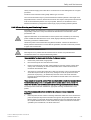
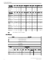
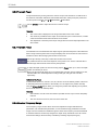
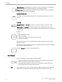
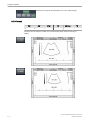
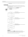
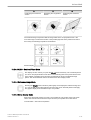
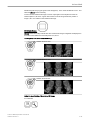
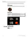
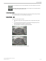
One of the recommended methods to disinfect the ultrasound probes is immersion
disinfection:
1.
Place the probe into the solution of cleaning-disinfectant. Make sure not to immerse the
probe into the liquid beyond the immersion level given in the pictures below. Make sure
that the probe is covered with the cleaning-disinfectant up to the immersion level during
the complete disinfection time. Leave the ultrasound probe in the solution for the time
specified by the manufacturer, see Probe Care Card.
Voluson™ E8/E8 Expert Basic User Manual
H48691CF Revision 2
2-19
Safety and Maintenance
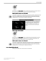
2.
Scrub the probe as needed using a soft sponge, gauze, or cloth to remove all visible
residue from the probe surface. Prolonged soaking or scrubbing with a soft bristle brush
(such as a toothbrush) may be necessary if material has dried onto the probe surface.
3.
Rinse the probe with enough clean, potable water to remove all disinfectant residues.
4.
Use a soft cloth to clean the cable and the user section of the probe with the cleaningdisinfectant liquid. Make sure that the surface of the probe and cable is wetted
thoroughly with the cleaning-disinfectant.
5.
Allow probe to air dry completely.
6.
Reconnect the probe to the ultrasound console and place the probe into its holder.
7.
Inspect the probe prior to use for damage or degeneration to the housing, strain relief,
lens and seal. Do not use a damaged or defective probe until it has been inspected and
repaired/replaced by a GE Healthcare Austria GmbH & Co OG Service Representative.
8.
Put a new sterile, legally marketed probe sheath over the probe prior to next use.
Other appropriate disinfection methods for ultrasound probes, such as wipe disinfection, may
be applied as an alternative to disinfection by immersion, provided that the products listed in
the Probe Care Card are used.
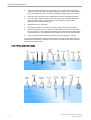
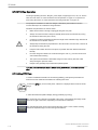
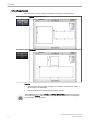
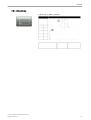
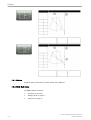
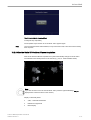
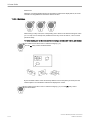
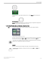
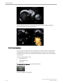
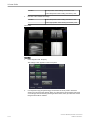
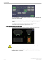
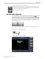
2.4.8.4 Probe Immersion Levels
2-20
Voluson™ E8/E8 Expert Basic User Manual
H48691CF Revision 2
Safety and Maintenance
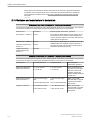
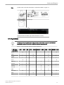
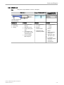
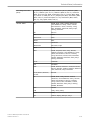
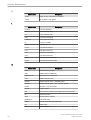
2.4.8.5 Planned Maintenance
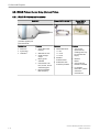
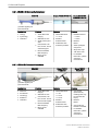
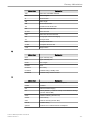
The following maintenance schedule is suggested for the system, probe and reusable biopsy /
biopsy bracket to ensure optimum operation and safety.
Do the Following
Daily
After / Before Each Use
As Necessary
X
X
Inspect the Probes
Clean the Probes
X
X
Disinfect endocavity
probes
X
Disinfect all other probe
types
X
X
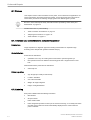
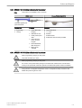
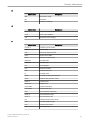
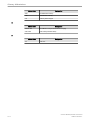
2.4.8.6 Environmental requirements for Probes
Probes must be operated, stored, or transported within the parameters outlined below.
Probe Environmental Requirements
Operational
Storage
Transport
+18º to +30º C
-10º to +50º C
-10º to +50º C
Humidity
30% to 75% noncondensing
10% to 85% noncondensing
10% to 85% noncondensing
Pressure
700hPa (3000m) to
1060hPa
700hPa (3000m) to
1060hPa
700hPa (3000m) to
1060hPa
Temperature
2.4.8.7 Using Protective Sheaths
Probes are not delivered sterile!
Before the first usage, it is MANDATORY to clean and disinfect probes to avoid infections or
disease transmissions!
Protective barriers may be required to minimize disease transmission. Probe sheaths are
available for use with all clinical situations where infection is a concern. Legally marketed,
sterile probe sheaths must be used for intracavitary procedures. Use of legally marketed,
sterile, pyrogen free probe sheaths is MANDATORY.
Instructions: Custom-made sheaths are available for each probe. Each probe sheath kit
consists of a flexible sheath used to cover the probe and cable and elastic bands used to
secure the sheath.
Sterile probe sheaths are supplied as part of disposable biopsy kits for those probes intended
for use in biopsy procedures. In addition to the sheath and elastic bands, there are associated
accessories for performing a biopsy procedure which are included in the kit. Refer to the
biopsy instructions, 'Biopsy Special Concerns' on page 2-22
Devices containing latex may cause severe allergic reaction in latex sensitive individuals.
Refer to FDA’s March 29, 1991 Medical Alert on latex products.
DO NOT use pre-lubricated condoms as a sheath.
In some cases, they may damage the probe. Lubricants in these condoms may not be
compatible with probe construction.
Voluson™ E8/E8 Expert Basic User Manual
H48691CF Revision 2
2-21
Safety and Maintenance
DO NOT use an expired probe sheath.
Before using probe sheaths, verify whether the term of validity has expired.
Probes must be cleaned and disinfected before they are replaced or disposed.
2.5 Biopsy Safety and Maintenance
2.5.1 Biopsy Special Concerns
Biopsy needles and biopsy guides are not delivered sterile unless it is clearly labeled! If
biopsy-equipment is not sterile it is MANDATORY to clean and disinfect biopsy needles and
biopsy guides before the first usage to avoid infections or disease transmissions!
If available, please also consult accompanying documents delivered with the biopsyequipment.
There may be restrictions on performing IVF, CVS or PUBS. Please consider the local laws
and regulations!
Caution
All biopsy equipment depicted and described in this Basic User Manual has been validated for
use with the system and software. Biopsy brackets provided by Civco are only validated with
needle guides Ultra Pro II. If biopsy equipment which is not listed in this Basic User Manual is
used, the user has the possibility to configure and store the predicted biopsy line. In this case
the user has to be aware that the biopsy equipment/probe/system/software combination may
not be validated and therefore responsibility for correct configuration and usage lies with the
user.
Caution
When performing a freehand biopsy, i.e. not using a biopsy guide, it is the user's responsibility
to use appropriate equipment. Ensure that the needle (especially the needle tip) is always
visible in the ultrasound image during the whole biopsy procedure.
2.5.1.1 Preparing the Patient
•
•
Prepare the patient according to the usual procedures for the purpose.
An ultrasound examination with this system must be performed either under supervision,
or by adequately trained and qualified medical staff.
A biopsy must only be performed by physicians with adequate experience. Under all
circumstances the necessary safety precautions and sterility measures have to be respected.
It is absolutely necessary to ensure that before performing a biopsy, the selected and
displayed biopsy line corresponds to the biopsy needle guide mounted to the transducer (left/
right).
2-22
Voluson™ E8/E8 Expert Basic User Manual
H48691CF Revision 2
Safety and Maintenance
Before starting a biopsy please make sure that in case you want to save a study, all relevant
patient information is entered.
Do not use needle guide if it appears damaged.
Cleaning and Sterilization of reusable Biopsy Guides: (for disposable biopsy guides, please
regard enclosed manuals):
After each use, remove needle guide from transducer. Remove visible contaminants from
needle guide surface thoroughly,using a small, soft instrument brush. Take special care of all
narrow areas and tubes. Keep needle guide from drying out until complete cleaning can be
accomplished. After that, soak needle guide for minimum of five minutes in neutral pH, low
foamingenzymatic detergent.
While immersed, use instrument brush to remove trapped contaminants from Surfaces, holes
and tubes. If visible contaminants cannot be easily removed, repeat soaking procedure for an
additional five minutes. Remove needle guide from cleaning solution and remove any
remaining residue with dry wipe. Follow cleaning solution manufacturer’s directions for use
and recommendations for concentration.
Disposable biopsy guides: Single-use components must be disposed as infectious waste!
Reusable biopsy guides must be sterilized before they are disposed!
2.5.2 Biopsy Lines
To achieve the best possible accuracy of the display of the needle path, the biopsy lines have
to be programmed for each transducer.
•
•
•
•
•
For more information see 'Biopsy line adjustment for single angle biopsy guide' on page
5-11.
For more information see 'Biopsy line adjustment for multi angle biopsy guide' on page 511.
The default biopsy lines provided with the system software, must be verified at least
once by the user. The procedure must be repeated if probes and/or biopsy guides are
exchanged.
Before performing a biopsy, make sure that the displayed biopsy line coincides with the
needle track (check in a bowl filled with approx. 47˚C warm water).
The needle used for this alignment verification must not be used for the actual
procedure. Always use a straight, new and sterile needle for each biopsy procedure.
Depending on the needle stiffness/thickness and the elasticity and composition of the different
tissue-types in the path of the biopsy needle, the actual needle track can deviate from the
predicted biopsy line. The biopsy needle might bend and not follow a straight line.
Voluson™ E8/E8 Expert Basic User Manual
H48691CF Revision 2
2-23
Safety and Maintenance
2.6 Manufacturer Responsibility
The manufacturer, assembler, importer or installer considers themselves responsible
regarding safety, reliability and performance of the instrument under the following conditions:
•
•
when assembling the system, when adding options, when new settings or modifications
or repairs were performed by personnel authorized by themselves,
also that the local electric installation complies with the national regulations, and that the
equipment is only used according to the User Manual.
2.7 Service Documents
The Service Manual supplies block diagrams, lists of spare parts, descriptions, adjustment
instructions or similar information which help adequately qualified technical personnel in
repairing those parts of the instrument which have been defined repairable by the
manufacturer.
2.7.1 Service Software – Remote Access
By using the remote access feature, a GE field engineer can access the ultrasound system via
a modem connection. The field engineers are required to contact/call the affected site in
advance prior to establish a connection to the system.
Disruptive Mode:
If the field engineer requires unrestricted access to the ultrasound system the field engineer
requests to create a disruptive mode on the system. A message appears on the screen asking
for permission to switch to disruptive mode:
GE Service is requesting permission to diagnose the system remotely. Normal system
operations might be disturbed during this period. Click on YES to allow GE Service to continue
system diagnostics.
If disruptive mode is accepted, work on the system can be severely affected. Therefore, it is
not allowed to perform an exam or make a diagnosis using the ultrasound system while being
in disruptive mode.
Note
A remote connection can affect the system’s performance (e.g., in 3D/4D or Doppler mode).
Therefore, it is recommended to cease work on the system as soon as the field engineer
contacts the site and announces the remote connection.
Network Security:
The remote access features enables, after checkout has been performed, network services
like ftp or telnet on the ultrasound system. Therefore, it is advisable to restrict network access
to system for unauthorized personnel. It is strongly recommended to use a firewall to restrict
network access from and to an ultrasound system with the remote access feature installed.
Other precautions like a secure network segment are encouraged.
2.8 Bioeffects and Safety of Ultrasound Scans
When ultrasound waves travel through tissue, there is a certain risk for damage. There has
been a lot of research on the impact that high frequency waves can have on different kinds of
tissues under defined conditions and “There is, to date, no evidence that diagnostic ultrasound
has produced any harm to humans – including the developing fetus.” (Guidelines for the safe
2-24
Voluson™ E8/E8 Expert Basic User Manual
H48691CF Revision 2
Safety and Maintenance
use of diagnostic ultrasound equipment, Safety Group of the British Medical Ultrasound
Society 2010).
Physiological effects due to ultrasound are generally assumed to be deterministic and only
occur above a certain threshold in contrast to ionizing radiation, which causes effects
accidentally. Thus ultrasound examinations can be held very safe if certain proceedings are
followed. It is therefore recommended to read the following sections and study the cited
literature.
2.8.1 Prudent Use – ALARA Principle
In spite of the relatively low risk of ultrasound scans compared to other imaging techniques,
the operator shall choose the exposure level with caution to minimize the risk of bioeffects.
“A fundamental approach to the safe use of diagnostic ultrasound is to use the lowest output
power and the shortest scan time consistent with acquiring the required diagnostic information.
This is the ALARA principle (i.e. As Low As Reasonably Achievable). It is acknowledged that
in some situations it is reasonable to use higher output or longer examination times than in
others: for example, the risks of missing a fetal anomaly must be weighed against the risk of
harm from potential bioeffects. Consequently, it is essential for operators of ultrasound
scanners to be properly trained and fully informed when making decisions of this nature.”
(Guidelines for the safe use of diagnostic ultrasound equipment, Safety Group of the British
Medical Ultrasound Society 2010)
Special care regarding ALARA should be taken with obstetric examinations as any potential
bioeffects are likely to be of greatest significance in the embryo or fetus.
It is strongly recommended to consider ALARA when undertaking ultrasound scans.
2.8.2 Bioeffects
•
•
Thermal effects refer to heating of soft tissue and bone
The thermal indices TIs (soft tissue), TIb (bone near focus) and TIc (bone near surface)
were introduced to provide the operator a relative potential for a tissue temperature rise.
According to the Standard for Real-time Display of Thermal and Mechanical Acoustic
Output Indices on Diagnostic Ultrasound Equipment (2004) those thermal indices shall
be displayed by this ultrasound console. It should be noted that a TI of 1 does not
necessarily mean that tissues being scanned will increase in temperature by 1˚C –
almost every scanning situation departs from the assumed model conditions, such as
tissue type, blood perfusion, mode of operation and actual exposure time of the scanned
area. However, the thermal indices provide information regarding the possible increase
in the risk of potential thermal bioeffects and it provides a relative magnitude that can be
used to implement ALARA. In addition to tissue heating due to the generated ultrasound
field, the temperature of the probe head itself can also increase during the examination.
The operator shall be aware, that in the tissue region near the ultrasonic transducer,
there will be a superposition with the heating due to the ultrasound field, which is not
considered by the TI values.
Nonthermal effects refer to mechanical phenomena such as cavitation
Nonthermal bioeffects are caused by the interaction of ultrasound fields with very small
pockets of gas (stabilized gas bodies), i.e. the generation, growth, vibration and possible
collapse of microbubbles within the tissue. This behavior is referred to as cavitation
(Medical Ultrasound Safety, 2nd Edition, AIUM 2009/American Institute of Ultrasound in
Medicine Consensus Report on Potential Bioeffects of Diagnostic Ultrasound, AIUM
2008/Guidelines for the safe use of diagnostic ultrasound equipment, Safety Group of
the British Medical Ultrasound Society 2010). The potential of cavitation increases with
Voluson™ E8/E8 Expert Basic User Manual
H48691CF Revision 2
2-25
Safety and Maintenance
the rarefactional peak pressure but decreases with the pulse frequency. Therefore the
Mechanical Index MI was introduced to take account of both the pressure and the
frequency. The higher the MI the greater is the risk of nonthermal bioeffects.
2.8.3 Regulated Parameters
Relevant parameters having physiological effects (For more information see 'Bioeffects' on
page 2-25. ) are regulated according to FDA and IEC guidelines and standards. These
parameters are
Parameter
Meaning
Limit
Displayed
MI
Mechanical Index
1.9
Yes
TIs, TIb, TIc
Thermal Indices TI – one of the
following values can be displayed:
6
Yes
TIs: soft tissues
TIb: bone in focal region
TIc: bone at surface (e.g. cranial)
Ispta.3
Averaged intensity at spatial peak
with a derating of 0.3dB/(cm MHz)
720 mW/cm2
No
T
Temperature at the patient’s side of
the probe – lower limit during patient
contact, higher limit for rest position
43˚C/50˚C
(109.4˚F/122˚F)
No
2.8.4 Interpretation of displayed parameters MI and TI
During obstetric examinations these displayed values shall be observed very critically,
because there may be conditions that are potentially hazardous even below the regulatory
limits.
Some guidelines recommend that embryonic and fetal in situ temperatures of 41˚C (4˚C above
normal temperature) should be limited in time by 5 min or less. Thus, for a reasonable safety
margin, TI values above 1 should be avoided. Additional factors, like fever of the mother, are
again reasons to keep the TI values as low as possible on the one hand, and go only as high
as necessary to achieve the desired clinical results ('Prudent Use – ALARA Principle' on page
2-25).
The mechanical index, which indicates the risk of cavitation, becomes important at the
interface between gas and soft tissue (nonfetal lung and bowel), but also with the use of gas
body contrast agents. Often an MI value of 0.4 or less is suggested for examinations of tissue
containing stabilized gas bodies. This value arises from operating experience and is not
confirmed.
Some examples where the MI and TI, respectively, are more or less important are shown in
the following table according to Particular requirements for the basic safety and essential
performance of ultrasonic medical diagnostic and monitoring equipment, IEC 60601-2-37 2nd
Edition, 2007, Annex CC.
2-26
Voluson™ E8/E8 Expert Basic User Manual
H48691CF Revision 2
Safety and Maintenance
Of greater importance
MI –
Mechanical
Index
TI –
Thermal
Indices
With contrast agents
Cardiac scanning (lung exposure)
Of less importance
In the absence of gas bodies, i.e. most
tissue scanning
Abdominal scanning (bowel gas)
1st trimester scanning
Well perfused tissue, i.e. liver, spleen
Fetal skull and spine
Cardiac scanning
Neonatal head
Vascular scanning
Patient with fever
Poorly perfused tissue
Scanning near ribs or bone: TIb
Further information can be retrieved from Bioeffects & Safety of Diagnostic Ultrasound, AIUM,
1993 and Evaluation of Research Reports: Ultrasound Bioeffects Literature Reviews
(1992-2003).
2.8.5 Reporting Tables
Acoustic output reporting tables according to the below cited standards are provided in the
Advanced Acoustic Output References.
Particular requirements for the basic safety and essential performance of ultrasonic medical
diagnostic and monitoring equipment, IEC 60601-2-37 2nd Edition, 2007.
Information for Manufacturers Seeking Marketing Clearance of Diagnostic Ultrasound Systems
and transducers, FDA Guidance, 2008.
Ultrasonics - Field characterization - Test methods for the determination of thermal and
mechanical indices related to medical diagnostic ultrasonic fields, IEC 62359 1st Edition, 2005.
2.9 Disposal
This symbol indicates that the waste of electrical and electronic equipment must not be
disposed as unsorted municipal waste and must be collected separately. Please contact the
manufacturer or other authorized disposal company to decommission your equipment
according to local regulations.
2.9.1 Battery disposal
Lithium battery included with this device. Do not puncture, mutilate or dispose of battery in fire.
Replace only with same type recommended by the manufacturer. Dispose of used battery
according to manufacturers instructions and in accordance with your local regulations.
The separate collection symbol is affixed to a battery, or its packaging, to advise you that the
battery must be recycled or disposed of in accordance with local or country laws. The letters
below the separate collection symbol indicate whether certain elements (Pb=Lead,
Cd=Cadmium, Hg=Mercury) are contained in the battery. To minimize potential effects on the
environment and human health, it is important that all marked batteries that you remove from
the product are properly recycled or disposed. For information on how the battery may be
Voluson™ E8/E8 Expert Basic User Manual
H48691CF Revision 2
2-27
Safety and Maintenance
safely removed from the device, please consult the service manual or equipment instructions.
Information on the potential effects on the environment and human health of the substances
used in batteries is available at this url http://www.gehealthcare.com/euen/weee-recycling/
index.html
2.10 Guidance and manufacturer´s declaration
Guidance and manufacturer´s declaration - electromagnetic emissions
The Voluson™ E8/E8 Expert is intended for use in electromagnetic environment specified below. The customer
or the user of the Voluson™ E8/E8 Expert should assure that it is used in such an environment.
Emission test
Compliance
Electromagnetic environment - guidance
RF emissions - CISPR 11
Group 1
The Voluson™ E8/E8 Expert uses RF energy only for
its internal function. Therefore, its RF emissions are
very low and are not likely to cause any interference in
nearby electronic equipment.
RF emissions - CISPR 11
Class A
Harmonic emissions IEC
61000-3-2
Class A
The Voluson™ E8/E8 Expert is suitable for use in all
establishments (i.e. hospitals, doctors practice etc.)
other than domestic. The Voluson™ E8/E8 Expert is
intended for professional use only.
Voltage fluctuations/
flicker emissions IEC
61000-3-3
Complies
Guidance and manufacturer´s declaration - electromagnetic immunity
The Voluson™ E8/E8 Expert is intended for use in electromagnetic environment specified below. The customer
or the user of the Voluson™ E8/E8 Expert should assure that it is used in such an environment.
Immunity test
IEC 60601 test level
Compliance level
Electromagnetic
environment- guidance
Electrostatic discharge
(ESD) IEC 61000-4-2
± 2,4,6 kV contact
± 2,4,6 kV contact
± 2,4,8 kV air
± 2,4,8 kV air
Floors should be wood,
concrete or ceramic tile. If
floors are covered with
synthetic material, the
relative humidity should be
at least 30 %.
Electrical fast transient/
burst IEC 61000-4-4
± 2kV for power supply
lines
± 2kV for power supply
lines
±1kV for input/output lines
±1kV for input/output lines
± 1kV differential mode
± 1kV differential mode
± 2kV common mode
± 2kV common mode
Surge IEC 61000-4-5
2-28
Mains power quality
should be that of a typical
commercial or hospital
environment.
Mains power quality
should be that of a typical
commercial or hospital
environment.
Voluson™ E8/E8 Expert Basic User Manual
H48691CF Revision 2
Safety and Maintenance
Guidance and manufacturer´s declaration - electromagnetic immunity
Voltage dips, short
< 5% UT
interruptions and voltage
(> 95% dip in UT)
variations on power supply
input lines IEC 61000-4-11 for 0.5 cycle
< 5% UT
(> 95% dip in UT)
for 0.5 cycle
40% UT
40% UT
(60% dip in UT)
(60% dip in UT)
for 5 cycles
for 5 cycles
70% UT
70% UT
(30% dip in UT)
(30% dip in UT)
for 25 cycles
for 25 cycles
< 5% UT
< 5% UT
(>95% dip in UT)
(>95% dip in UT)
for 5 s
for 5 s
Power frequency magnetic 3 A/m
field (50/60Hz) IEC
61000-4-8
3 A/m
Mains power quality
should be that of a typical
commercial or hospital
environment.
Power frequency magnetic
fields should be at levels
characteristic of a typical
location in a commercial
and hospital environment.
NOTE: UT is the a.c. mains voltage prior to application of the test level
Guidance and manufacturer´s declaration - electromagnetic immunity
TheVoluson™ E8/E8 Expert is intended for use in electromagnetic environment specified below. The customer
or the user of the Voluson™ E8/E8 Expert should assure that it is used in such an environment.
Portable and mobile RF communications equipment should be used no closer to any part of the Voluson™
E8/E8 Expert, including cables, than the recommended separation distance calculated from the equation
applicable to the frequency of the transmitter.
Immunity test
IEC 60601 test level
Compliance level
Conducted RF IEC
61000-4-6
3Vrms / 150kHz to 80 Mhz 3Vrms
Radiated RF IEC
61000-4-3
3 V/m; 80MHz to 2.5 GHz
Electromagnetic
environment- guidance
Recommended separation
distance
3 V/m
80MHz to 800 MHz
800MHz to 2.5GHz
Voluson™ E8/E8 Expert Basic User Manual
H48691CF Revision 2
2-29
Safety and Maintenance
Guidance and manufacturer´s declaration - electromagnetic immunity
where P is the maximum output power rating of the transmitter in watts (W) according to the transmitter
manufacturer and d is the recommended separation distance in meters (m). Field strength from fixed RF
transmitters, as determined by an electromagnetic site survey, (a) should be less than the compliance level in
each frequency range.(b) Interference may occur in the vicinity of equipment marked with following symbol:
NOTE:
a) Field strength from fixed transmitters, such as base stations for radio (cellular/cordless) telephones and land
mobile radios, amateur radio, AM and FM radio broadcast cannot be predicted theoretically with accuracy. To
access the electromagnetic environment due to fixed RF transmitters, an electromagnetic site survey should be
considered. If the measured field strength in the location in which the Voluson™ E8/E8 Expert is used exceeds
the applicable RF compliance level above, the Voluson™ E8/E8 Expert should be observed to verify normal
operation. If abnormal performance is observed, additional measures may be necessary, such as reorienting or
relocating the Voluson™ E8/E8 Expert. b) Over the frequency range 150 kHz to 80 MHz, field strengths should
be less than 3 V/m. In the working frequency range of the ultrasound system from 1 to 30 MHz an influence on
the ultrasound image can be visible in the presence of electromagnetic radiation at 200 to 500mV/m depending
on the probe connected.
Recommended separation distances between portable and mobile RF communications equipment and the
Voluson™ E8/E8 Expert
The Voluson™ E8/E8 Expert is intended for use in an electromagnetic environment in which radiated RF
disturbance are controlled. The costumer or the user of the Voluson™ E8/E8 Expert can help prevent
electromagnetic interference by maintaining a minimum distance between portable and mobile RF
communications as recommended below, according to the maximum output power of the communications
equipment.
Rated maximum output
power of transmitter W
Separation distance according to frequency of transmitter m
150 kHz to 80 Mhz
80 MHz to 800 Mhz
800 MHz to 2,5 GHz
0.01
0.12
0.12
0.233
0.1
0.37
0.37
0.74
1
1.17
1.17
2.33
10
3.7
3.7
7.4
1
11.7
11.7
23.3
For transmitters rated at a maximum output power not listed above, the recommended separation distance d in
meters (m) can be estimated using equation applicable to the frequency of transmitter, where P is the maximum
output power rating of the transmitter in watts (W) according to the transmitter manufacturer.
Note 1 At 80MHz and 800MHz, the separation distance for the higher frequency range applies.
Note 2 These guidelines may not apply in all situations. Electromagnetic propagation is affected by absorption
and reflection from structures, objects and people.
2-30
Voluson™ E8/E8 Expert Basic User Manual
H48691CF Revision 2
Safety and Maintenance
2.11 Network disclosure
Purpose and scope
This disclosure is intended to satisfy the requirements of IEC 60601-1:2005 clause 14.13 and
IEC/ISO 80001-1:2010 clause 3.5 for disclosure of network-related specifications,
requirements and residual risks in order to facilitate the responsible organization's risk
management activities (e.g. pursuant to 80001-1) for their networks incorporating the
Voluson™ E8/E8 Expert.
Purpose of the network connection
The connection options (USB, Ethernet, WLAN, Bluetooth) provide a possibility for data
transfers from and to the Voluson™ E8/E8 Expert. This allows the customer to use a
convenient database system for data management and data sharing e.g. within a hospital or
any other relevant organizations. Also simple standard device connections, such as printers,
USB storage devices or similar, are provided by the USB connection for data exchange.
Network interface technical specifications
Physical and link layer interface:
Ethernet IEEE 802.3 10BASE-T, 100BASE-TX and
1000BASE-T
Internet Protocol Version:
IPv4
IP-Addressing:
static or DHCP
Physical and link layer interface:
WLAN IEEE 802.11b/g
Internet Protocol Version:
IPv4
IP-Addressing:
static or DHCP
Enabled Host-to-Host communication protocols:
•
•
•
•
•
DNS – Only used as client.
DHCP – Only used as client.
NetBIOS – Name, Datagram, Session services, Network file share MS network. Only
used as client.
Insite ExC – Device servicing by GE Remote Service.
1
ACR/NEMA Digital Imaging and Communications in Medicine (DICOM® )
•
•
DICOM Conformance Statement: http://www.gehealthcare.com/usen/
interoperability/dicom/products/ultrasound_dicom.html
IHE Integration Statement: http://www.gehealthcare.com/usen/interoperability/
ihe.html
Required IT network characteristics
Minimum throughput 100 Mbit/sec, recommended 1Gbit/sec for large image file transfer
Ports open to Internet: 3003 - Insite ExC
1
DICOM is the registered trademark of the National Electrical Manufacturers Association for its standards publications
relating to digital communications of medical information.
Voluson™ E8/E8 Expert Basic User Manual
H48691CF Revision 2
2-31
Safety and Maintenance
Ports open only to secure LAN closed to Internet:
•
•
•
•
53 – DNS Client
68 – DHCP Client
104 – DICOM
137,138,139, 445 – Netbios/Fileshare
Potential hazardous situations resulting from failures of the IT network
The following general hazardous situations have been identified as potentially arising as a
result of the IT network failing to provide the required characteristics specified above:
•
•
•
Delayed or impaired access to images or other exam information or patient data.
Permanent loss of images or other exam information or patient data.
Corruption of images or other exam information or patient data.
In addition to the hazardous situations identified above, connection of the Voluson™ E8/E8
Expert to a network that includes other equipment could result in other unidentified risks to
patients, operators or third parties. The responsible organization should identify, analyze,
evaluate and control these risks on an ongoing basis including after changes to the network
such as those listed below, which could introduce new risks and require additional analysis.
•
•
•
•
•
2-32
changes in network configuration
connection of additional items to the network
disconnection of items from the network
update of equipment connected to the network
upgrade of equipment connected to the network
Voluson™ E8/E8 Expert Basic User Manual
H48691CF Revision 2
Chapter 3
Description of the System
Describes the console overview and operator controls.
Sections in this chapter:
•
•
•
•
•
•
•
'Product Description' on page 3-2
'System Assembly' on page 3-3
'Mechanical Adjustment' on page 3-4
'Concept of Operation' on page 3-7
'Layout of Menus' on page 3-7
'Button description' on page 3-11
'Electronic User Manual (EUM)' on page 3-16
Voluson™ E8/E8 Expert Basic User Manual
H48691CF Revision 2
3-1
Description of the System
3.1 Product Description
The Voluson™ E8/E8 Expert is a professional, innovative, most versatile real-time scanning
system.
It opens new sonographic possibilities with the 3D/4D VOLUME scanning technique. The vast
array of probes makes it suitable for many applications.
Diagnostic possibilities:
2D Mode
Additional Operating Modes (B-Flow, XTD-View)
M Mode (M+Color Flow Mode)
Spectral Doppler (Pulsed- and Continuous Wave)
Color-Doppler (Velocity-, Power-, Tissue imaging and HD-Flow)
Volume Mode (3D sectional image analysis interactive 3D rendering and
Real Time 4D)
Note
The application fields are dependent on the selected probe.
The system is designed for follow-up expansion.
Operable probes:
•
•
Multi-element probes (linear array, curved array, phased array and pencil probes)
Real Time 4D Volume probes
The operation is designed for the specific clinical requirements and ensures simple and
efficient handling. Vast ranges of measuring and evaluation programs, as well as many special
functions enable comfortable working. The interface with interface software provides quick
digital archiving of images and/or volume data sets on mass storage medium. A network
interface (Ethernet) provides documentation in DICOM standard.
3-2
Voluson™ E8/E8 Expert Basic User Manual
H48691CF Revision 2
Description of the System
3.2 System Assembly
1. Monitor rotate and height adjust- and
inclinable
2. Loudspeaker
3. Control console rotate and height
adjustable
4. Touch panel display
5. Probe holder
6. Place for B&W printer
7. Place for printer or DVR
8. Shelf with probe connectors
This module houses the entire
electronics for connections, up to 4
probe connectors and the beam former
module (transmit and receive
electronics)
9. Footrest
10. DVD drive or DVR box
11.+ 12.
3 casters with brake, 1 caster without
brake
3.2.1 Optional Peripheral Devices
See 'System Options' on page 18-11 for a list of peripheral and hardware options.
See Chapter 17 for details on connecting peripheral devices.
3.2.2 Optional Modules
Optional modules (CW Doppler, Real Time 4D, etc.) according to the price list of the
Voluson™ E8/E8 Expert.
Voluson™ E8/E8 Expert Basic User Manual
H48691CF Revision 2
3-3
Description of the System
3.3 Mechanical Adjustment
Be sure to have read all mechanical adjustment safety informations before proceeding:
For more information see 'Mechanical adjustment safety' on page 2-11.
Be careful when adjusting mechanical parts of the equipment.
•
•
•
Ensure nothing is jammed.
Do not put your hands or other body parts between movable parts of the equipment.
Be careful when adjusting or locking the monitor.
3.3.1 Mechanical Monitor Adjustment
The monitor can be rotated, moved forward and backward and adjusted in height:
Incline the monitor
Move back and forth
Move up and down
3.3.1.1 Lock monitor parts
Lock height adjustment:
Move the upper monitor arm parallel to the lower arm and push it down (1), the lock it by turning the knob
(2).counterclockwise. Release by turning the knob clockwise.
Lock arm rotation:
3-4
Voluson™ E8/E8 Expert Basic User Manual
H48691CF Revision 2
Description of the System
Rotate the arm to center position and turn the knob (1) clockwise till the rotation is locked. Release by
turning the knob counterclockwise.
3.3.1.2 Preparing for transport
To ensure that no part of the monitor can be damaged when transporting or moving the
system, the monitor has to be in a secure position.
1.
Lock all monitor parts.
2.
Incline the monitor to horizontal position:
The system can now be safely transported. Nevertheless be careful when transporting or
moving the device.
3.3.2 User interface adjustment
The user interface can be rotated, moved forward and backward and adjusted in height.
Voluson™ E8/E8 Expert Basic User Manual
H48691CF Revision 2
3-5
Description of the System
Moving the user interface
1. Press UI Brake/Release on the user interface to release the
brake.
2. Grab the front handle and move the user interface to the desired
position.
3. Press UI Brake/Release again to lock the brake.
Note
The brake can be released for a maximum of 30 seconds. Then the
brake hardware needs a recovery time of about one minute. The
following message will be shown on screen: "Brake recovery required
- Floating of the keyboard will be available again after a short
recovery interval!"
Adjusting the user interface in height
1. Press UI Elevation on the user interface and keep it pressed.
The Elevation menu appears on the touch panel.
2. Press up or down on the touch panel and keep the button pressed
to adjust the user interface.
The user interface moves in the desired direction.
3. Release the touch panel button to stop at the desired position.
3.3.3 Caster Brakes
Never move the system with blocked wheels, but block the wheels in the proximity of stairs
and ramps.
There are 3 casters that can be braked. The following positions are available:
Front casters: Position 1, 2, 3
Rear caster: Position 1, 2
Position 1
Position 2
Position 3
Middle position: caster
freely movable
Lower position:
steering blocked +
brake engaged
Top position: steering
blocked.*
* The steering will only be blocked when the wheel is in center position.
3-6
Voluson™ E8/E8 Expert Basic User Manual
H48691CF Revision 2
Description of the System
3.4 Concept of Operation
The control center of the Voluson™ E8/E8 Expert is the console with the digipot controls, the
hard keys and the trackball. The console controls frequently used functions, e.g., Freeze/Run,
change of modes, etc. Additional functions are controlled via the touch panel.
3.4.1 Touch panel
The touch panel consists of the flat control monitor.
Note
The touch panel could be blocked by direct sunlight - avoid full sunlight. The touch panel will
be blocked by any foreign body lying on it, or e.g. by remainder of coupling gel - clean the
touch panel regularly (with a wetted soft cloth).
The touch panel enables a comfortable control of menus. Only those touch keys are provided
which are necessary for the activated menu. The touch panel eases working under dim light
condition.
3.4.2 Digipot controls, Trackball
Activated functions are easily controlled by these controls. When rotated they deliver digital
pulses and can be selected by program call-up. They are displayed on the touch panel screen
by their location, their function, and their actual value of setting.
A dual function is marked e.g.: [Βbalance +/-]. Touching [+] causes an increase of balance.
Touching [-] causes a decrease of balance
3.5 Layout of Menus
Mainly two menu levels are used for operating the system, the main-menu level and the
submenu level. From the main menu the most important submenus, e.g. adjusting the 2D
image are directly accessible. Some hard keys activate a specific submenu on the touch
panel, e.g. the Archive key. Normally changing from one submenu to another is made via the
main menu; direct call-up from one to another submenu is possible in some rare cases only.
3.5.1 Layout of the 2D Mode Main Menu
All B-Mode operations are started from this menu. It contains 4 main groups of operating
functions:
Voluson™ E8/E8 Expert Basic User Manual
H48691CF Revision 2
3-7
Description of the System
Main group 1:
•
•
•
•
•
•
•
•
•
•
•
•
Main group 2:
Main menu keys for:
Presets
Sub window probe dependent functions
Image up/down
Image left/right
Virtual Convex Mode
FFC (Focus and Frequency Composite)
XBeam CRI (CrossBeam Compound Resolution Imaging) CE (Coded
Excitation)
SRI (Speckle Reduction Imaging)
Image Angle
β-View (Beta View)
Focal ZonesOTI (Optimized Tissue Imaging)
Frequency
Sub menu keys for:
adjusting the 2D image
Main group 3:
Main group 4:
Menu Utilities keys for:
•
•
•
•
System Setup
Biopsy
Histogram
etc.
Change from write-only functions to read-only functions when changing
read/write (Freeze/Scan):
Remarks:
Selecting a new mode displays a new “Main” menu with the operating functions of this mode.
The keys for the functions Focus, OTI, β-View, Frequency, Angle, Virtual Convex Mode, FFC,
CE, XBeam CRI and SRI only appear on the touch panel if they are available for the selected
probe.
3.5.2 Changing of Menus
Each menu has its own menu key with a “topic” name. By touching the menu key the referring
menu appears on the touch panel. The keys for the different sub-menus can be found next to
the “Main” menu key on the touch panel.
Remark: If no probe is selected, the “PROBE/PROGRAM” menu is displayed.
3-8
Voluson™ E8/E8 Expert Basic User Manual
H48691CF Revision 2
Description of the System
3.5.3 Position of Display Annotation
1.)
Logo
16.)
Status bar area
2.)
Patient Name (Last-, First-,
Middle Name)
17.)
P Buttons
3.)
Patient ID-number; GA
(Gestational Age)
18.)
Run/Freeze/Cine
4.)
Probe / Application
19.)
Trackball
5.)
Depth / Frame rate
20.)
-
6.)
Mechanical Index
21.)
Message Area
7.)
Thermal Index
22.)
Clipboard History
8.)
Sonographers Name
23.)
Current Clipboard
9.)
Hospital Name (Identification)
24.)
Bodymarks
10.)
Date
25.)
Depth scale markers
11.)
Time
26.)
Gray scale wedge
12.)
Image Info
27.)
Focal zones marker
13.)
TGC curve
28.)
Orientation marker.
14.)
Image area
29.)
Second patient ID
15.)
Measurement results
3.5.3.1 Detailed Image information
Image Info:
B (2D) Mode
User program
Name of user program
7.5-5.0
Receiver frequency [MHz]
85
Acoustic power or fixed to maximum power 100
Gn -12
Gain [dB]
Voluson™ E8/E8 Expert Basic User Manual
H48691CF Revision 2
3-9
Description of the System
Image Info:
B (2D) Mode
C5 / M7*
Dynamic curve [number] and Gray map [number]*
P6 / E4
Persistence [number] and Edge enhancement [number]
Image Info:
M Mode
Gn 10
Gain [dB]
150/C1
max. Dynamic range [dB] and selected Dynamic curve [number]
EE 1
Edge enhancement [number]
Rej 10
Reject [number]
Image Info:
D (PW, CW) Mode
85
Acoustic power or fixed to maximum power 100
Gn 10
Gain [dB]
WMF 230 Hz
Wall motion filter [Hz]
SV Angle 60˚
Angle correction
Size 2.5 mm
Sample volume size
Depth 21.2mm
Sample volume depth
Frq mid
Transmit frequency [Probe data]
PRF 1.2 kHz
Velocity Range [kHz, cm/s, m/s]
Image Info:
CFM-Mode, PD-Mode, HD-Flow Mode
85%
Acoustic power or fixed to maximum power 100
Gn 6
Gain [dB]
Frq mid
Transmit frequency [Probe data]
Qual mid
Quality of CFM [table]
WMF mid
Wall motion filter [table]
PRF 1.2 kHz
Velocity Range [kHz, cm/s, m/s]
Th45 / S5/5
Threshold [number] and Smooth rise/fall [number] (3D/CFM + 3D/PD
only)
Image Info:
3-10
3D/4D Mode
User program
Name of 3D/4D user program
Th26 / Qual high1
Threshold [number] and Quality [table]
B68˚ / V55˚
Angle of the Volume Box [degree] and Volume Angle [degree]
Mix 16/84
Mix between selected render modes [percent]
S.txt / S.sm
selected render modes
M14 / 1
Gray Map Position [number] and Contrast [number]
T1.
Acquisition Time [seconds]
S1mm
Slice Thickness [centimeters]
Mode
selected Acquisition Mode
Voluson™ E8/E8 Expert Basic User Manual
H48691CF Revision 2
Description of the System
Remarks:
•
•
When the Automatic Optimization function is active, an asterisk (* next to the Gray map
number) is displayed in the B mode Image Info area.
The Image Info in 3D/4D Mode depends on the selected Acquisition and Visualization
Mode.
3.5.4 Control Panel
1.Loudspeaker position
2. Touch panel screen
3. TGC Slider controls
4. Touch panel digipot controls
5. Touch panel flipswitch controls
6. Mode keys (digipot controls)
7. Toggle switch controls
8. Trackball
9. Alphanumeric Keyboard
10. Hard keys
11. Trackball buttons
12. digipot controls
13. Probe holders
3.6 Button description
Stand-by
UI Level Adjustment
Allows you to turn the system on or put it
in standby mode.
Allows you to adjust the height of the
User Interface, see 'User interface
adjustment' on page 3-5
Utilities
Patient Data Entry
Allows you to switch to the utilities menu,
'Utilities' on page 14-2
Switch to the patient data entry menu (the
previous exam will be closed). For more
information see 'Entering Patient Data' on
page 4-7.
Probe Program
Review
Switch to the Probe Program menu for
selecting a probe with its related program.
For more information see 'Probe
selection' on page 4-5.
Switch to the exam review mode, For
more information see 'Selecting Exams'
on page 13-43. . Unless no exam has
been started, then pressing the [Review]
key opens the Archive, For more
information see 'Patient Archive' on page
13-11. .
Voluson™ E8/E8 Expert Basic User Manual
H48691CF Revision 2
3-11
Description of the System
End Exam
Play/Record
Patient and measurement data are stored
in the “Data manager” and all temporary
patient and measurement data are
cleared. Operation: Caution:
Press this key once to change the touch
panel to the “DVD/VCR/DVR remote
control menu”.,
For more information see 'P-keys' on
It is absolutely necessary to press this
key before switching OFF the system.
Otherwise the current Patient data as well
as all the measurements in the Patient
report will be lost.
Press this key twice to start a recording
on the connected DVD recorder or video
recorder.
Elastography
Tissue Doppler
Pressing activates/deactivates the
Elastography Mode. Functions depend on
current probe. For more information see
Chapter 9.
Pressing activates/deactivates the Tissue
Doppler Mode. Functions depend on
current probe. For more information see
'Tissue Doppler Mode (TD Mode)' on
Power Doppler
Contrast Imaging
Pressing activates/deactivates the Power
Doppler mode. Functions depend on
current probe.
Pressing activates/deactivates the coded
Contrast Imaging function. Functions
depend on current probe. For more
information see 'Contrast Imaging' on
For more information see 'Power Doppler
Mode (PD Mode)' on page 8-15.
page 15-3.
Press this key twice to stop the recording.
page 8-23.
page 6-35.
XTD-View (Extended View)
B-Flow
Pressing activates/deactivates the XTDView function. Functions depend on
current probe. For more information see
'XTD-View (Extended View)' on page 6-
Pressing activates/deactivates the B-Flow
function. Functions depend on current
probe. Operation: For more information
see 'B-Flow' on page 6-25.
Continuous Wave Doppler
Report (Worksheet)
Pressing activates/deactivates the
Continuous Wave Doppler. Functions
depend on current probe. For more
information see 'Continuous Wave
Doppler Mode (CW Mode)' on page 8-
Activates the Patient worksheet of the
currently selected application. For more
ABC - Image Annotation
Bodymark
Write a comment/annoation directly onto
the screen. For more information see
'Image Annotation' on page 4-26.
Activate to use Bodymark symbols on the
screen. For more information see
'Pictogram' on page 4-31.
27.
information see Chapter 11.
7.
3-12
Voluson™ E8/E8 Expert Basic User Manual
H48691CF Revision 2
Description of the System
Automatic Optimization
Clear
in 2D Mode: Press this key to use
automatic optimization on the gray scale
to enhance the contrast resolution. For
more information see '2D Automatic
Optimization' on page 6-5. in PW
Mode: Press this key to use automatic
optimization on the PRF and the
Baseline. Operation: For more
information see 'PW Operation' on page
8-3. in 3D/4D Mode: Press this key to
activate Sono Render Start. For more
information see 'Sono Render Start' on
To erase graphics, measurements and
annotations on the screen, depending on
the currently used function.
page 10-92.
•
•
•
•
If image annotation is active, then
only text will be erased.
If the measurement function is active,
then only measurements will be
erased.
If bodymark is active, then only
bodymarks will be erased
If none of the three above functions is
active, all graphics, measurements
and annotations will be erased.
Pointer
Coded Harmonic Imaging
Single click: Brings up an arrow shaped
cursor for menu and image operations.
Pressing activates/deactivates the Coded
Harmonic Imaging. For more information
see ' Harmonic Imaging (HI)' on page 6-
Double click: Activates the Indicator menu
For more information see 'Indicator' on
page 4-30.
7.
Exit
Caliper
Press the [Exit] key on the control panel
to exit the current menu.
For more information see 'Generic
Measurements' on page 11-2.
Calculations
Real Time 4D Mode
Allows measurements/calculations in
2D/3D mode, M mode and SpectralDoppler mode, using various measure
items for different applications For more
Activates the Real Time 4D mode
(continuous volume sweep) For more
information see 'Real Time 4D
Acquisition' on page 10-79.
3D
P1
Activates 3D mode (Volume Mode)
Chapter 10
For more information see 'P-keys' on
page 15-3.
P2
P3
Programmable key, For more information
see 'P-keys' on page 15-3.
Programmable key, For more information
see 'P-keys' on page 15-3.
P4
Freeze/Scan (Read/Write)
Programmable key, For more information
see 'P-keys' on page 15-3.
When bright: image is frozen (freeze
mode). When dark: real time scan (scan
mode). For more information see 'Probe
selection' on page 4-5.
Acoustic Output (digipot)
Dual-Screen Format (vertical distribution)
Adjusts the Ultrasound emission power of
a probe. 'Transmit Power' on page 6-6
Select the display format (Dual screen
display) in 2D and 3D image mode. For
more information see 'Multi Format' on
information see Chapter 11.
page 6-10.
Voluson™ E8/E8 Expert Basic User Manual
H48691CF Revision 2
3-13
Description of the System
Quad-Screen Format
Single-Screen Format
select the display format (Quad screen
display) in 2D and 3D image mode. For
more information see 'Multi Format' on
Select the display format (Single screen
display) in 2D and 3D image mode. For
more information see 'Multi Format' on
Depth (flipswitch)
Focus (flipswitch)
Select the display depth of the 2D image
using the flip switch. For more information
see '2D Mode Depth' on page 6-4.
Select position of transmit focus using the
flip switch For more information see
'Transmit Focus' on page 6-6.
HR Zoom/ Pan Zoom (digipot)
UI Brake Release
Allows you to modify the Zoom ROI and
choose a Zoom mode.
Locks and unlocks the user interface
brake.
For more information see 'Zoom' on page
6-12.
'User interface adjustment' on page 3-5
Pulsed Wave Doppler (on/off)
Motion Mode (on/off)
Pressing activates/deactivates the PW
Doppler mode. Functions depend on
current probe. Rotating allows setting of
the PW mode gain within the probedefined range. For more information see
'Pulsed Wave Doppler Mode (PW Mode)'
Pressing activates/deactivates the M
mode. Functions depend on current
probe. Rotating allows setting of the M
mode gain within the probe-defined
range. For more information see Chapter
Power Doppler
Color Mode (on/off)
Pressing activates/deactivates the Power
Doppler mode. Functions depend on
current probe. Rotating allows to set the
Power Doppler gain and HD-Flow gain
within the probe-defined range. When
using 3D mode, turning the button will
rotate the volume on the Z-axis.
Pressing activates/deactivates the Color
mode. Functions depend on current
probe. Rotating allows setting of the CFM
mode gain within the probe-defined
range. For more information see 'Color
Flow Mode (CFM)' on page 8-10.
page 6-10.
on page 8-2.
page 6-10.
7.
For more information see 'Power Doppler
Mode (PD Mode)' on page 8-15.
2D Mode (all additional modes will be
switched off)
For more information see Chapter 6.
Pressing this control activates 2D Mode.
Rotating allows you to set the 2D image
gain within the probe-defined range
For more information see '2D Gain' on
page 6-4.
Trackball and Trackball keys trackball:
positions cursors, Cine-loop, position and
size of the box, etc. upper trackball key:
changes the actual trackball function left/
right trackball key: sets, fixates cursors
and activates pages/buttons, etc.
Double click functions are displayed in
brackets.
3.6.1 Function of the Trackball at Diverse Dialog Pages
In general operations at diverse dialog pages and windows on the system desktop (e.g.,
Patient Data Entry, Usage of EUM, System Setup, Measurement Setup, etc.) are executed by
trackball and the trackball keys (mouse emulation).
3-14
Voluson™ E8/E8 Expert Basic User Manual
H48691CF Revision 2
Description of the System
Trackball (mouse position):
positions the cursor (arrow) on
the desktop
Left trackball key (left mouse
button)
sets, fixates markers and
activates pages/buttons etc.
marked by the cursor
Upper trackball key (right mouse
button)
Right trackball key (left mouse
button)
no function in system desktop
sets, fixates markers and
activates pages/buttons etc.
marked by the cursor
DICOM Spooler
Eject
Opens the DICOM job spooler
window on screen, 'Connectivity'
Opens a dialog window with all
medias that can be ejected.
Remove USB Devices
Delete Measurements
Opens a dialog window with all
medias that can be unplugged,
Deletes all measurements.
Set Home/Home
Delete Abc
An image annotation function, For
more information see 'Annotation'
Deletes all image annotations in
the preselected layer.
Text A/ Text B
Arrow/Indicator
Switch to the Image annotation
menu, For more information see
'Auto Annotation' on page 4-27.
Toggles the shape of the cursor.
You can choose between 2
shapes (hand/arrow), For more
information see 'Auto Annotation'
3.6.2 Keyboard keys
on page 14-31
For more information see
'Remove USB Devices' on page
17-4.
on page 4-27.
on page 4-27.
Voluson™ E8/E8 Expert Basic User Manual
H48691CF Revision 2
3-15
Description of the System
EUM
Press the [F1] button to invoke
the electronic user manual.
Operation: For more information
see 'Electronic User Manual
(EUM)' on page 3-16.
Up/ Down
Function
Activates additional keys on the
keyboard. Additional key
functions are framed on the key
(e.g. Set Home).
Page up/ Page down
Switch between the next or
previous page.
Print Screen
Copies an image of the current
screen to the connected USBStick or HDD.
Left / Home
Right / End
Moves left or with the “Fn” key to
home position. For more
information see 'Auto Annotation'
Moves right or with the “Fn” key
to end position. For more
information see 'Auto Annotation'
on page 4-27.
on page 4-27.
3.7 Electronic User Manual (EUM)
Press the [F1] key on the keyboard to invoke the electronic user manual.
The EUM screen appears (e.g.: 2D Mode)
The Help screen is divided into three sections:
3-16
1.
Navigation Tools on the top, left portion (Hide, Back, Forward, Print, Options)
2.
Help Book - Navigation Tools on the left portion of the screen (Contents, Index, Search,
Favourites)
3.
Content portion on the right side of the screen where help topics are displayed
Voluson™ E8/E8 Expert Basic User Manual
H48691CF Revision 2
Description of the System
3.7.1 Navigation Tools
[Hide] the Help book navigation tools on the left portion of the screen.
To view the left side of the screen again, click the [Show] icon.
To go back to the previous selected topic.
To view the topic which was displayed before clicking the [Back] button.
To print the selected topic or the selected heading and all subtopics.
Choose the desired printer, select the “Page Range” and click the [Print] button.
Please be aware that changes and modifications, which are not related to installing printers
and adjusting printer settings may cause system dysfunction.
Do NOT change the “Default Printer” setting. This will change also the “Report Printer” setting
in the System Setup.
To adjust different functions (e.g. Search Highlight ON/OFF).
3.7.2 Help Book - Navigation Tools
Online Help is organized like a manual, with individual chapters, sections and pages.
Click on the Help book navigation tools on the left portion of the screen:
3.7.2.1 To View the Contents
1.
Click on the [+] sign next to the chapter you want to view to open up that section.
Voluson™ E8/E8 Expert Basic User Manual
H48691CF Revision 2
3-17
Description of the System
2.
Open up the page to view that page’s information.
The blue, underlined text links you to related topics.
After you click on the blue, underline text, the screen updates with this link’s content. To return
to the previous screen click [Back]. To return to the link, click [Forward].
3.7.2.2 To Use the Index
1.
Click on the “Index” tab. A list of topics - arranged in alphabetical order - will be
displayed.
2.
Use the scroll bar to look up a topic.
3.
Either double click the desired topic to view, or highlight the topic and click the [Display]
button.
3.7.2.3 To Search for a Topic
3-18
1.
To search for a specific topic, click on the “Search” tab.
2.
Type in the topic name in the Type in the keyword to find: field. Topics with the word or
phrase you typed appear in the Select Topic to display: area.
3.
Either double click the desired topic to view, or highlight the topic and click the [Display]
button.
Voluson™ E8/E8 Expert Basic User Manual
H48691CF Revision 2
Description of the System
3.7.2.4 To Save a Favorite Topic
You may find that there are topics you need to refer to often. In this case, it is a good idea to
save these topics as Favorites.
1.
To save a topic as a favorite, click on the “Favorites” tab.
2.
Highlight the topic in the Topics: field and click the [Add] button.
You can now view this topic quickly by going to the Favorites help tab.
3.7.3 To Exit the Electronic User Manual
Touch [Exit] on the touch panel, press the [Exit] key on the control panel to exit the electronic
user manual.
Voluson™ E8/E8 Expert Basic User Manual
H48691CF Revision 2
3-19
Description of the System
This page was intentionally left blank.
3-20
Voluson™ E8/E8 Expert Basic User Manual
H48691CF Revision 2
Chapter 4
Operating the System
Describes powering on the system, transducer connection, program selection and patient data.
Sections in this chapter:
•
•
•
•
•
•
'General Remarks' on page 4-2
'System Start-Up' on page 4-2
'Probe connection and selection' on page 4-4
'Entering Patient Data' on page 4-7
'Image Annotation' on page 4-26
'Scan Assistant' on page 4-33
Voluson™ E8/E8 Expert Basic User Manual
H48691CF Revision 2
4-1
Operating the System
4.1 General Remarks
Installation, switching on for the first time and check-up of the system must only be performed
by authorized persons.
The Voluson™ E8/E8 Expert is delivered with recommended basic settings. These offer
suitable conditions for a large number of applications. Depending on the user’s experience
these default settings can be changed and stored as new User Programs. Storing these
programs or quick loading of new programs of a second user is done by Backups.
Be sure to have read all system and probe safety information before proceeding:
For more information see 'System Safety and Maintenance' on page 2-7.
For more information see 'Probe Safety and Maintenance' on page 2-14.
4.2 System Start-Up
4.2.1 Power On
Never use an adapter that would defeat the safety ground.
The system must only be connected to a fully intact main socket with a grounded guard wire
via an appropriate main cable. The ground wire must never be removed or disconnected.
1.
Connect the Power Cable to the back of the system.
2.
Connect the Main Power Cable to a hospital grade power receptacle with the proper
rated voltage.
3.
Switch ON the Main switch at the rear of the system.
4.
To switch on the system, press the Standby switch located to the left of the touch panel.
1: Main Switch
Standby switch
Once system is switched on, it is completely reset. The boot-up time is about 2 minutes, and
then the 2D mode main menu for the previously selected transducer is displayed. In case you
disconnect the previously selected transducer, the menu "Probe Select" will appear, even if it
has been disconnected during shutdown.
In case software version and user program version are not identical, a message will be
displayed during boot up:
4-2
Voluson™ E8/E8 Expert Basic User Manual
H48691CF Revision 2
Operating the System
Message window
Message
The current user programs are not compatible
with this software version. Incompatibility of user
programs and software version may lead to
reduced image quality. Please open Utilities System Setup - Backup page and load the latest
available backup (Small Backup).
4.2.2 Power Off
To avoid loss of the current Patient data as well as all the measurements in the Patient
Worksheet, it is absolutely necessary to press the [End Exam] key on the control panel before
switching OFF the system. For more information see 'Ending an exam' on page 4-11.
1.
•
To switch off the system, press the Standby switch located to the left of the touch panel
once. The shutdown dialog appears. The information in the dialog will vary depending on
the processes that may be active during shutdown.
Normal shutdown
Press the [Shutdown] soft key or press the Standby switch to switch off the system.
Press the [Restart] soft key to restart the system.
Press the [Cancel] soft key, the [Exit] button on the touch panel or the [Exit] hard key to return
to the previous operating state.
•
•
If you are currently saving images, the following dialog appears.
If a service technician is currently remote servicing your system, the following dialog
appears.
Voluson™ E8/E8 Expert Basic User Manual
H48691CF Revision 2
4-3
Operating the System
•
•
1.
If the current Exam is not finished, the following message will be displayed.
During Full Backup or Image Backup a shutdown is not possible. If you press the
Standby switch, the following dialog appears:
After the system is fully powered off, you may switch OFF the Main switch at the rear of
the system.
Remarks:
•
•
The main outlets of the system for peripheral equipment are commonly switched with the
Standby switch. So the auxiliary equipment need not to be switched on/off separately.
After turning off the system, wait at least ten seconds before turning it on again. The
system may not be able to boot if power is recycled too quickly.
4.3 Probe connection and selection
4.3.1 Probe connection
Prior to connecting or disconnecting a probe freeze the image. It is not necessary to switch off
the system. If a probe is disconnected while running (scan mode) a software error may occur.
In this case switch OFF the system and, after an interval of 10 seconds, switch it ON again.
(perform a reset).
If the cable spout on the right-hand door is missing do not pull on the probe cable, the probe
cable can be damaged. Please insert the spout in the destined place or call the Service
Department.
Connecting a probe:
1.
Plug the probe connector into a free socket.
2.
Turn the probe lock-lever to vertical position. Ensure that the probe sits tight.
3.
Place the probe cable in the cable holder.
Disconnecting a probe:
4-4
1.
Freeze the image by pressing the [Freeze] key.
2.
Turn the probe lock-lever to horizontal position.
3.
Remove the probe.
Voluson™ E8/E8 Expert Basic User Manual
H48691CF Revision 2
Operating the System
A disconnection of an active probe is permitted in freeze mode (frozen image) If a probe is
disconnected while running (scan mode) a software error can occur!
4.3.2 Probe selection
The probe selection menu shows the connected probes. The denomination of each transducer
connected to the system appears in the corresponding touch key (soft key). Probe selection is
done by touching the corresponding key. The key with the selected probe is illuminated. At the
same time the available applications of the selected probe are displayed in the application
field. Upon selection of an Application, a maximum of 7 User program buttons appear in the
“Settings” field, and a Default Setting. The Default Setting is not user-definable. Program
selection is done by pressing the corresponding keys. For each probe up to 7 programs can
be stored. The Probe/Program Selection Menu enables speedy adjustment of the system for
different fields of application. To store a user setting under an application, review: 'General' on
page 14-14
Probe selection menu on the touch panel:
[Probe] key (hard key): This key activates and deactivates the “probe select” menu. Behavior
of probe select function, when connecting/disconnecting a probe, review: 'Probe connection
and selection' on page 4-4
Voluson™ E8/E8 Expert Basic User Manual
H48691CF Revision 2
4-5
Operating the System
Probe window: Shows all connected probes, the active one is highlighted (if one is active)
Application window: Shows all applications for the active probe. The last active application is
highlighted.
Settings (program) window: Shows all settings for the active application. The last active setting
is highlighted.
To load a setting touch the corresponding setting key. The probe is initialized, the main menu
(2D mode) appears on the touch panel and the ultrasound image appears on the monitor in
scan mode (real time display).
Alternatively, pressing the [Freeze] key also causes loading of the selected (highlighted)
setting. The probe starts (real time display)
Selecting a probe:
Touch the corresponding probe key. Each touch key shows the name of the responding probe
and a picture. The selected probe is indicated when its key is highlighted. At the same time the
“Application” fields appear. Upon selection, the programmed “Settings” come into view (8
setting keys for selection of the desired setting).
Freezing an image:
Freeze/Run-key (hard key) Freeze the image by pressing the [Freeze] key: Bright key: freeze
mode (image is frozen, probe deactivated) Dark key: scan mode (real-time is on, probe
activated)
Exit:
4-6
Voluson™ E8/E8 Expert Basic User Manual
H48691CF Revision 2
Operating the System
To return to the previously used active mode menu (2D mode, M mode,.....) without any
changes press the soft key [Exit] or the hard key [Probe]. This is only possible if no change of
a probe or an application was made. If a change was made in the “Application” field, the key
turns dark (disabled). In this case an exit is only possible by selecting a setting.
4.4 Entering Patient Data
Patient Data is to be entered by using a patient data form. This information will be used in
calculations, patient worksheets, DICOM settings and is displayed on the screen to identify
images. All entries into the data fields are stored on the internal database.
Press the [Patient] key (hard key) on the control panel.
Touch panel and screen change to the:
Patient Menu
If an exam is started; For more information see 'Current Patient Menu' on page 4-12.
“Patient Information” screen
If no exam is started; For more information see 'Patient Information screen' on page 4-14.
Voluson™ E8/E8 Expert Basic User Manual
H48691CF Revision 2
4-7
Operating the System
If the system is connected to a work list server (e.g. HIS / RIS) you can select a patient from
the list.
•
•
Operation: For more information see 'To Retrieve Patient Data via External Work list
Server' on page 4-21.
Otherwise use the keyboard to type in the Patient Information. Operation: For more
information see 'Standard Input' on page 4-8.
4.4.1 Standard Input
Selecting an input field
There are 3 possibilities to select an input field:
•
Using the trackball
Trackball: position the cursor in the input field
Enter: select an input field; press the right or left trackball key
•
Using the touch panel
Touch the corresponding key on the touch panel.
4-8
Voluson™ E8/E8 Expert Basic User Manual
H48691CF Revision 2
Operating the System
Note
If you touch the [Name] key repeatedly, the write cursor jumps from the “Last Name” to the
“First Name” and to the “Middle Name” input field.
•
Using the keyboard
Press the [Enter] or [Tab] (input fields are selected in successive order).
Entering patient information
Use the keyboard to type the patient information.
Upon pressing the [Enter] key on the keyboard the data is entered and the next input field is
selected.
Note
If the “Capitalize Letter in Patient Names” field in the System Setup is marked by a check mark
the first letter in the “Name” fields will be automatically capitalized. For more information see
'General' on page 14-14.
Remarks:
•
•
The system automatically creates a Patient Identification (ID) number. To create your
own ID number, overwrite the automatic ID number using the keyboard.
Patient data on different systems are only distinguished by the patient Identification (ID)
field! If you do not use the default auto-generated ID please make sure that this
Identification (ID) is unique on all systems for the same patient!
4.4.2 Starting an exam
To start an exam press [Start Exam] on the touch panel, see 'Current Patient Menu' on page
4-12
”Start Exam” is also possible by pressing the [2D] key, the [Freeze] key on the control panel or
the upper trackball key.
Voluson™ E8/E8 Expert Basic User Manual
H48691CF Revision 2
4-9
Operating the System
If temporary measurements exist, no old patient exists and no save/send in progress and no
auto-start acquisition, the system will display an info dialog “Start Exam with previous
measurements?” on the touch panel and on the monitor.
To quit the dialog: [Yes]: The current measurements are dedicated to the Exam. [No]: The
current measurements and the screen are cleared and 2D starts.
The Patient procedure is closed and the previous operating state is activated.
If no old patient exists, no save/send in progress and no auto-start acquisition, the system will
display an info dialog “Start Exam with old ultrasound image?” on the touch panel and on the
monitor.
Note
If Auto Start Acquisition is selected, the system automatically starts a new acquisition in 2D
Mode when Start Exam is pressed, without displaying the dialog. For more information see
'General' on page 14-14.
To quit the dialog: [Yes]: The exam starts without further action (with old image). [No]: The
screen is cleared and 2D starts.
The Patient procedure is closed and the previous operating state is activated.
4-10
Voluson™ E8/E8 Expert Basic User Manual
H48691CF Revision 2
Operating the System
4.4.3 Ending an exam
[End Exam]: Exit from the patient procedure to previous operating state.
Patient and measurement data are stored in the “Data manager” and all temporary patient and
measurement data are cleared.
It is absolutely necessary to press the [End Exam] key on the control panel before switching
OFF the system. Otherwise the current Patient data as well as all the measurements in the
Patient Worksheets get lost.
If the “End Exam Dialog” field in the System Setup is marked by a check mark, the”End Exam”
dialog will be displayed on the monitor before ending the current exam.
For more information see 'General' on page 14-14.
1. Incomplete measurement exists:
Select No: Dialog window disappears (exit to previous operating state)
Select Yes: “End Exam” command is executed and the dialog window disappears.
2. No incomplete measurement exists:
Select No: Dialog window disappears (exit to previous operating state)
Select Yes: “End Exam” command is executed and the dialog window disappears.
•
•
Patient ID exists: Patient and measurement data are stored in the “Data manager” (all
temporary patient and measurement data are cleared).
No Patient ID exists: all temporary measurement data are cleared
Note
All files will be compressed when ending a exam. The status of the compression is indicated
with a status bar on the lower left user interface.
Note
The “End Exam” command is also executed if the [End Exam] key/button is pressed again
while the dialog window is displayed.
Note
If a DICOM Printer is configured to print by “End Exam” and the printing page is not full the
following message appears:
Voluson™ E8/E8 Expert Basic User Manual
H48691CF Revision 2
4-11
Operating the System
Note
If “Don’t display this message again” is checked, the message box will not be displayed before
printing.
4.4.4 Current Patient Menu
Current Patient Menu (touch panel)
Archive:
Switches to Archive. For more information see Chapter 13.
Start Exam:
Starts an exam with the current patient.
Exit
Patient procedure to previous operating state. All patient information which has been entered
previously will be cleared.
4-12
Voluson™ E8/E8 Expert Basic User Manual
H48691CF Revision 2
Operating the System
Search:
Switches to search mode.
All other buttons refer to the field of the same name on screen.
Current Patient menu (screen)
Archive:
Switches to Archive. For more information see Chapter 13.
Clear Current:
All temporary patient and measurement data is cleared For more information see 'Patient
Information screen' on page 4-14. If MPPS is used, and a step is in progress, send MPPS
discontinue message to cancel the step.
Hide Patient Info:
Hides the patient info on screen during an exam
Start Exam:
Starts an exam with the current patient. The patient information is temporarily stored. This can
also be done by pressing the upper trackball key.
Voluson™ E8/E8 Expert Basic User Manual
H48691CF Revision 2
4-13
Operating the System
Exit:
Exit the patient procedure to previous operating state. All patient information which has been
entered previously will be cleared.
Note
The ID number cannot be edited. If 3D/4D data are loaded from Archive back into the system,
editing is impossible (the [Edit] key is grayed). If Patient Dialog is open, it is possible to start
and stop recording by pressing the DVD/VCR button.
4.4.5 Patient Information screen
1. Enter Patient Data.
Area
Note
Description
max. Characters
Patient ID:
ID number
32
2nd Patient ID:
Additional ID number (only
64, depends on
available if checkbox is activated in system settings
the System Setup)
Last Name:
patient’s last name
First Name:
patient’s first name
Middle Name:
patient’s middle name
DOB (Day of Birth)
patient day of birth
-
Age
patient age
-
Sex
----, female, male (selection in pull
down menu)
-
62 (all fields together)
Upon entering the day of birth: The age is calculated and displayed automatically.
2. Select Application.
•
•
4-14
Patient Information – Abdomen (ABD)
Patient Information – Obstetrics (OB)
Voluson™ E8/E8 Expert Basic User Manual
H48691CF Revision 2
Operating the System
•
•
•
Patient Information – Gynecology (GYN)
Patient Information – Cardiology (CARD)
Patient Information – Urology (URO)
3. Enter the required Application Data for the selected Application.
4. Enter additional Study Information.
Area
Description
max. Characters
Perf. Physician:
Name of the Performing Physician
32
Ref. Physician:
Name of the Referring Physician
32
Sonographer:
Name of Sonographer
32
Exam Type:
comment input
32
Accession #
accession number
16
Indication:
Indication
32
Custom 1:
custom input field 1
32
Custom 2:
custom input field 2
32
5. Exam List of the Selected Patient
If an existing patient file has been selected, then all the exams of this patient will be displayed
in this area. One exam can be marked for further manipulation by using the trackball.
For more information see 'Standard Input' on page 4-8. or 'To Search in the Patient List' on
page 4-25
4.4.5.1 Patient Information – Abdomen (ABD)
Application Data:
Height: Enter the patient’s height in one of the dimensions (cm, ft., inch). Weight: Enter the
patient’s weight in one of the dimensions (kg, lb., oz.).
Dimension selection: Position the cursor into the Dimension selection field using the trackball
and press the left or right trackball key. The different dimensions will appear (in a successive
order) for selection.
Note
For more information see 'Patient Information screen' on page 4-14.
Voluson™ E8/E8 Expert Basic User Manual
H48691CF Revision 2
4-15
Operating the System
4.4.5.2 Patient Information – Obstetrics (OB)
Application Data:
LMP
Enter the date of the last menstrual period using the selected format (e.g.,
mm-dd-yyyy).
Note: The first day of the last period must be entered.
DOC
Enter the date of conception.
EDD
Enter the estimated date of delivery, GA is calculated automatically.
Can be changed to 41 weeks.
GA
GA will be calculated automatically after entering the date of the last
menstrual period (LMP) or the estimated date of delivery (EDD). “LMP” in
brackets denotes that GA was calculated. For future exams, the GA will be
calculated from the LMP.
When entering the Gestational Age (GA), EDD and DOC are calculated
automatically.
“CLIN” in brackets denotes that the GA was tested. For future exams, the GA
will be calculated from the GA.
Gravida
Enter the patient’s history of pregnancies.
Para
Enter the patient’s history of live births.
Aborta
Enter the patient’s history of abortions.
Ectopic
Enter the patient’s history of ectopic pregnancies.
Fetus #
Enter the fetus number (e.g., at twins “2”).
•
•
When entering LMP, the GA and EDD fields automatically show the calculation results.
When entering GA only EDD is calculated; when entering EDD only GA is calculated.
LMP/GA d/EDD calculation
Duration of gestation:
Note
4-16
28 days
EDD
=
LMP + 28d
Can be changed to 41 weeks
GA
=
actual date – LMP (actual date = date of Voluson™ E8/E8
Expert)
LMP
=
EDD – 28d
For more information see 'Patient Information screen' on page 4-14.
Voluson™ E8/E8 Expert Basic User Manual
H48691CF Revision 2
Operating the System
Select this button to invoke the Past exam dialog. (Only available if application is OB)
It is possible to switch between fetus tables, if more than one fetus is entered in the patient
dialog page.
Note
This dialog is used to enter data from previous ultrasound exams, performed on other
systems. This data can then be used for fetal trending (graphs). Which measurements are
listed depends on the current measure setup settings. On all further pages the measurement
columns change but the exam date column remains the same.
If no LMP is available the system uses the current date – the length of pregnancy used for
calculations.
This field shows the start and the end date of the Exam.
Create a new entry by entering an exam date (values between actual date and LMP are
possible).
Enter measurement data from previous exams performed on different systems.
Use the “Up/Down” arrows to scroll through the list, if the list is longer than the available
amount of lines.
Voluson™ E8/E8 Expert Basic User Manual
H48691CF Revision 2
4-17
Operating the System
Use these buttons or the [Prev.] or [Next] keys on the touch panel to go to previous or next
page.
Use this button to delete the entry.
Following message appears:
Select [Yes] if you want delete exam, select [No] if you want to proceed.
Use this button or the [Cancel] key on the touch panel to return to patient dialog page without
saving data.
Use this button or the [Save&Exit] key on the touch panel to return to the Patient Dialog Page
and save data.
Note
Only data that was entered via the past exam dialog is shown. (Measurements from exams
performed on this machine are not listed). Data that was entered via the past exam dialog
page is to be used in the fetal trending and those exams will be listed in the previous report
section as well. For more information see 'Obstetric Calculations in 2D Mode' on page 12-22.
4.4.5.3 Patient Information – Gynecology (GYN)
Application Data:
4-18
Voluson™ E8/E8 Expert Basic User Manual
H48691CF Revision 2
Operating the System
LMP
The first day of the last menstrual period must be entered using the
selected format (e.g., mm-dd-yyyy).
Note: The first day of the last period must be entered.
Note
Exp. Ovul.
Date of expected ovulation
Day of Cycle
Day of cycle
Day of Stim.
Day of Stimulation
Gravida
Enter the patient’s history of pregnancies.
Para
Enter the patient’s history of live births.
Aborta
Enter the patient’s history of abortions.
Ectopic
Enter the patient’s history of ectopic pregnancies.
For more information see 'Patient Information screen' on page 4-14.
4.4.5.4 Patient Information – Cardiology (CARD)
Application Data:
Height
Enter the patient’s height in one of the dimensions (cm, ft., inch)
Weight
Enter the patient’s weight in one of the dimensions (kg, up, oz.)
BSA
Body Surface Area (calculation value, no input)
HR
Heart Rate
Dimension selection: Position the cursor into the dimension field using the trackball and press
the left or right trackball key. The different dimensions will appear (in successive order) for
selection.
Note
The BSA value is calculated automatically, after entering height and weight. If Height and/or
Weight are entered in other dimensions (inch, lb.), first convert to kg and cm before calculation
of the BSA can take place!
Calculation formula for BSA:
WT [kg], HT [cm], BSA [m2]
Note
For more information see 'Patient Information screen' on page 4-14.
Voluson™ E8/E8 Expert Basic User Manual
H48691CF Revision 2
4-19
Operating the System
4.4.5.5 Patient Information – Urology (URO)
Application Data:
PSA
Enter the value of the Prostate-specific antigen
PPSA Coefficient 1
Enter the 1st value of the predicted PSA Coefficient.
PPSA Coefficient 2
Enter the 2nd value of the predicted PSA Coefficient.
Note
The PPSA is a number in dimensions of ng/ml/grams which gives the normal level of PSA that
would be expected for a prostate of a given volume. Predicted PSA = Volume (grams) x
0.15ng/ml/g (the Coefficient factor is adjustable in the Measure Setup)
Note
For more information see 'Patient Information screen' on page 4-14.
4.4.5.6 Edit Patient Information
Touch [Edit Data] The key is available in the Archive - Patient Menu 'Patient Menu' on page
13-21 or in the 'Exam Menu' on page 13-23
Note
4-20
If 3D or 4D data are loaded from Archive back into the system, editing is impossible (the [Edit
Data] key is grayed).
Voluson™ E8/E8 Expert Basic User Manual
H48691CF Revision 2
Operating the System
For more information see 'Standard Input' on page 4-8.
Press [Cancel&Return] to discard your changes and return to the previous operating state.
Press [Save&Return] to save your changes and return to the previous operating state.
Note
The ID number cannot be changed!
4.4.6 To Retrieve Patient Data via External Work list Server
Select the [Worklist] button to view the available Data from the external worklist server. This
button is available in the ('Patient Information screen' on page 4-14 ).
Voluson™ E8/E8 Expert Basic User Manual
H48691CF Revision 2
4-21
Operating the System
To sort the list of exams click the appropriate caption, e.g. Date/Time as image above.
Whatever criterion you choose for ordering your list will be indicated by a blue triangle and
stored.
Select the desired “Search” field with the trackball or the corresponding key on the touch
panel. “%” can be used as a wildcard.
Click this button (or the [Search] key on the touch panel) to search for the corresponding input.
Note
If a procedure with more than one procedure step is retrieved from the worklist, only one entry
is created. The number of steps is given in the S# column.
Highlight the result using the trackball cursor and the left or right trackball key [Set].
Click either this button or touch the [Select] key on the touch panel.
4-22
Voluson™ E8/E8 Expert Basic User Manual
H48691CF Revision 2
Operating the System
Note
To start an exam directly from the worklist, press the button Start Exam in the bottom right
corner of the worklist window by touching the space bar or the middle trackball key.
Note
The data from the worklist is filled into the patient information dialog, if no MPPS Server and
no procedure information are available.
'Connectivity' on page 14-31
Following actions are possible, if MPPS Server is available and procedure information
available:
1. Highlight an entry from this list using the trackball and press the central trackball button.
Detailed DICOM information is displayed:
Select one of this buttons to navigate through the detailed DICOM information of the relevant
procedure steps.
Select the [Close] button to return to worklist.
2. Highlight an entry from this list using the trackball and press the [Select] button.
The “Procedure Step” dialog is displayed:
Voluson™ E8/E8 Expert Basic User Manual
H48691CF Revision 2
4-23
Operating the System
Note
The procedure step dialog lists all procedure steps belonging to the selected procedure. The
header section displays the most important information of the selected step.
Highlight an entry from this list using the trackball and press the central trackball button.
Detailed DICOM information is displayed.
The status of a step can be none (not started), in progress, completed or discontinued.
Select this button to complete the step by sending a MPPS complete message (only possible if
status of step is “in progress”).
Select this button to cancel a step by sending a MPPS discontinue message (only possible if
status of step is “in progress”).
Select this button to start the procedure not immediately, but only after pressing “Start Exam”
in the patient dialog (only possible if no other step is “in progress” and status of step is not
started).
Select this button to start exam immediately without returning to the Patient dialog (only
possible if no other step is “in progress” and status of the step is not started.
Select this button to return to worklist dialog or to the patient menu (depending on where the
procedure step was started from).
4-24
Voluson™ E8/E8 Expert Basic User Manual
H48691CF Revision 2
Operating the System
Touch the [Exit] key on the touch panel. Exit from the Worklist search screen. No result will be
copied.
Please note:
The [Worklist] button can only be selected if a “Service: WORKLIST” DICOM address is
specified in the System Setup. To specify a DICOM Address: 'Connectivity' on page 14-31
4.4.7 To Search in the Patient List
Select the [Search] button using the trackball cursor and enter with the left or right trackball
key.
Note
In System Setup - General - Patient Info Display there is a check box “Automatically List
Patients”. If this check box is marked, all exams will be displayed automatically upon pressing
search. If this check box is unmarked no exams will be displayed when you press [Search]
until you click the [Show All] button on the screen.
This button is available on the “Patient Information” screen ( For more information see 'Patient
Information screen' on page 4-14. ).
The “Search Results” dialog menu appears on screen.
Voluson™ E8/E8 Expert Basic User Manual
H48691CF Revision 2
4-25
Operating the System
Search procedure:
•
•
•
Enter ID or Name into the corresponding input field using the keyboard keys. “%” can be
used as a wildcard.
Select the result using the trackball cursor and the left or right trackball key. The result is
highlighted. Double-clicking selects and copies the result immediately to the “Patient
Information” screen.
or click the [Select Patient] button
The search result will be copied to the patient dialog screen. The “Patient Information” screen
( For more information see 'Patient Information screen' on page 4-14. ) appears again.
k the [Show All] button and all Patients will be displayed on screen, as shown on the picture
above.
Exit from the search dialog screen, no result is copied. The “Patient Information” screen ( For
more information see 'Patient Information screen' on page 4-14. ) appears again.
4.5 Image Annotation
4-26
Voluson™ E8/E8 Expert Basic User Manual
H48691CF Revision 2
Operating the System
[ABC] - Annotation key (hard key) Press this key to start the documentation function. You can
also press [Space bar] to start the documentation function. Upon pressing the [ABC]
Annotation key once more the text is switched off but the annotation text is not cleared.
There are two possibilities provided to write on the screen:
•
•
Annotation ( 'Annotation' on page 4-27 ): with the keyboard keys
Auto Annotation ( 'Auto Annotation' on page 4-27 ): with the touch panel keys,
annotation with predefined words
4.5.1 Annotation
This function enables text writing onto the ultrasound image using the keyboard, in freeze
mode or in scan mode, respectively. The inscription will be erased upon selection of a probe or
a program. Inscription is not possible outside the annotation area.
Using text annotation
1.
Activate the Annotation Mode via [ABC] key or [Space Bar].
2.
Position the cursor:
•
•
position the cursor with the trackball or the arrow keys on the keyboard or
press Home on the keyboard to jump to the home position
3.
Write the text desired using the keyboard.
4.
Press the Enter key to start a new line. Press the Backspace key to delete the last
character.
Storing and activating a cursor position
1.
Press Fn + Home on the keyboard to store the current cursor position as home position.
2.
Press Home to position the cursor at the home position.
Note
An individual home position can be stored for each application. If desired, check the checkbox
Home position application specific in the System Setup. For more information see 'General' on
page 14-14.
Note
For more information see 'Keyboard keys' on page 3-15.
4.5.2 Auto Annotation
This function is provided to rapidly insert terms into the displayed image. 40 words for each
application are user-programmable. Programming of the TEXT AUTO function: For more
information see 'General' on page 14-14.
Voluson™ E8/E8 Expert Basic User Manual
H48691CF Revision 2
4-27
Operating the System
Touchscreen
Screen
1.
Activate the Annotation Mode with the [ABC] key or [Space bar]. The auto annotation
menu appears on the touch panel and on screen.
2.
Touch a “word” button or select the same word from the screen using the trackball. The
selected word appears at the cursor position. Select a new word, (a “blank” is inserted
between the prior and new word) or enter a character using the keyboard (a “blank” is
inserted between the prior word and the new character).
Text function is switched off but the entered text is not cleared. Return to the last
active menu.
Pressing the [Text Layer A] button either on the touch panel or on the screen, or the
[Text A] key on the keyboard displays the Text Layer A, and makes it available for
modification and deletion.
4-28
Voluson™ E8/E8 Expert Basic User Manual
H48691CF Revision 2
Operating the System
Pressing the [Text Layer B] button either on the touch panel or on the screen, or the
[Text B] key on the keyboard displays the Text Layer B, and makes it available for
modification.and deletion.
Pressing the [Text Layer A+B] button, either on the touch panel or on the screen,
displays both layers at the same time. Pressing the button again deactivates the
function and only the pre-selected layer will be displayed.
Pressing the [Hide Text] button, hides the text of all layers on the screen as well as
on printer, report and VCR/DVR, but does not delete it.
This key has two functions:
1. Turning the digipot highlights the words of the pre-selected layer one after the
other.
2. Pressing the digipot deletes the highlighted word. Pressing [Delete, Backspace]
on the keyboard also deletes the highlighted word.
Pressing the upper trackball key highlights the words of the pre-selected layer one
after the other.
All the text of the preselected layer in the annotation area is cleared.
Delete the last written word
The cursor jumps to current home position (Init position).
The 1st, 2nd…. page of auto text words appears. 1: current page / (2): number of
available pages
The current cursor position is stored as home position.
Touch an application key to select different application-related terms.
Note
The main application (chosen in the “Probe Selection” menu) does not change! After touching
the [Appl.] key the touch panel changes to the “Application Select” menu. When a “main”
application in the “Probe Selection” menu is selected, the text application is set (changed) to
this application.
Remarks:
Voluson™ E8/E8 Expert Basic User Manual
H48691CF Revision 2
4-29
Operating the System
•
•
The position of the cursor (“Home” position) can be changed by either:
•
•
•
•
Trackball
[Arrow] keys (left, right, up, down),
[Enter] key (next line), or
[Backspace] key (deletes the last character)
The Trackball, the [Home] key, or the arrow keys on the keyboard can set the left margin
of the image annotation.
4.5.3 Indicator
Indicator menu
Operation:
1.
Press the [F7] key or double click the Pointer key to activate the Indicator menu on the
touch panel. The last selected indicator appears in the middle of the annotation area.
2.
Select the type of indicator you want, or use the current indicator.
3.
Position the indicator using the track ball.
4.
Adjust the direction of the indicator (digipot, 360˚ rotation possible)
5.
Enter the indicator by pressing the right or left track ball key [Set].
6.
A new indicator is set by repeating procedures 3. through 5. When the trackball is moved
the next indicator appears.
Exit:
The Indicator function is switched off but the previous entered indicator remains uncleared.
Return to the last active menu.
4-30
Voluson™ E8/E8 Expert Basic User Manual
H48691CF Revision 2
Operating the System
Delete Last:
Last action (an entered indicator) is cleared.
Delete All:
All entered indicators in the annotation area are cleared.
4.5.4 Pictogram
Pictogram Display (body marks)
For the documentation of the scan position on the patient, a selection of graphic body symbols
(body marks) is available. A short bright line indicates the scan position. This line can be
positioned freely on the bodymark symbol.
Pressing the [Bodymark] key causes the touch panel to change to the Bodymark menu. The
previously used bodymark is shown on the screen.
Operation:
1.
The last selected pictogram appears in the last selected place of the annotation area.
2.
To change the displayed pictogram select the pictogram of your choice on the touch
panel.
Voluson™ E8/E8 Expert Basic User Manual
H48691CF Revision 2
4-31
Operating the System
Use the upper trackball key to switch between moving or rotating the scan plane identification
line direction with the trackball.
Move or rotate the scan plane identification line direction.
Press the left or right trackball key to fix the scan plane identification line and return to the last
active menu with the bodymark displayed
Note
The scan plane identification is shown in the scan mode and the freeze mode.
Press [Exit] to return to the last active menu with the bodymark displayed.
Press [Exit + Off] to return to the last menu with the bodymark switched off.
Touch an application key to change between the different application-related bodymarks.
After selecting another application the menu changes back to the Bodymark menu with the
bodymark symbols of the selected application.
Return to the Bodymark menu, if no new application is selected.
Note
4-32
The main application (chosen in the “Probe Selection” menu) does not change! After touching
the [Appl.] key the touch panel changes to the “Application Select” menu. When a “main”
application in the “Probe Selection” menu is selected, the Bodymark application is set
(changed) to this application.
Voluson™ E8/E8 Expert Basic User Manual
H48691CF Revision 2
Operating the System
4.6 Scan Assistant
General: Scan Assistant is an option. If this option is not installed, the [Scan Assistant] feature
is hidden.
The Scan Assistant tracks all measurements. It will also be listed in the worksheets.
To activate or edit the Scan Assistant:
For more information see 'General' on page 14-14.
To activate the Scan Assistant for the patient:
For more information see 'Application Area' on page 13-4.
The Scan Assistant can be confirmed with a P-key:
For more information see Chapter 15.
or the [Enter] key on the keyboard. Depending on the settings that are made in the
Systemsetup>General>Scan Assistant.
(1) See the Scan Assistant by clicking on the [Scan Assistant] tab.
(2) Drop down menu to switch between the activated Scan Assistant lists.
(3) All Scan Assistant items. Confirmed items will have a check mark in the box.
(4) Switch between page 1 and 2 to see all items.
Pause the Scan Assistant
Press the “Pause” button:
The Scan Assistant will no longer track the measurements in the list. To reactivate press the
pause button again. This can also be activated with the [F2] key on the keyboard.
Voluson™ E8/E8 Expert Basic User Manual
H48691CF Revision 2
4-33
Operating the System
This page was intentionally left blank.
4-34
Voluson™ E8/E8 Expert Basic User Manual
H48691CF Revision 2
Chapter 5
Probes and Biopsies
This chapter describes probes and biopsies and provides information on intended use and
applications.
Sections in this chapter:
•
•
•
'Probes' on page 5-2
'Biopsies' on page 5-8
'Overview of all probes and biopsies' on page 5-13
Voluson™ E8/E8 Expert Basic User Manual
H48691CF Revision 2
5-1
Probes and Biopsies
5.1 Probes
This chapter consists of the information for each probe, such as features and applications. As
well as informations for biopsies and biopsy-guides, such as biopsy kits and accessories as
well as basic procedures for attaching a biopsy guide to the different types of probes.
Be sure to have read all probe safety informations before proceeding: 'Probe Safety and
Maintenance' on page 2-14
Detailed information on probe handling:
•
•
•
'Probe connection and selection' on page 4-4
'Preparing the Transducer' on page 2-16
'Probe selection' on page 4-5
5.1.1 Intended use, contraindications and patient population
Intended use
Image Acquisition for diagnostic purposes including measurements on acquired image.
Extracting tissue samples with guided and freehand biopsy.
Contraindications
Probes are not intended for:
•
•
ophthalmic use or any use causing the acoustic beam to pass through the eye
intra-operative use that is defined as introducing probe into a surgical incision or burr
hole
Abdominal and linear probes are not intended for:
•
endocavity use
Patient population
•
•
•
•
•
Age: all ages (incl. embryos and fetuses)
Location: worldwide
Sex: male and female
Weight: all weight categories
Height: no height limitations
5.1.2 Labeling
Each probe is labeled with the following information:
•
•
•
•
5-2
Manufacturer
GE part number
Probe serial number
Probe designation provided on the top of the connector housing, so it is easily read when
mounted on the system and is also automatically displayed on the screen when the
probe is selected.
Voluson™ E8/E8 Expert Basic User Manual
H48691CF Revision 2
Probes and Biopsies
Note
Symbols used on the label: 'Description of symbols and labels' on page 2-3
1. Probe type
Displayed Probe Information (1 = Probe Information Location)
5.1.3 Applications
The manual refers to probes that can be connected to the device. It might be possible that
some probes, options or features are NOT available in some countries!
Below is a list of all probes and their intended applications.
2D Probe
Applications
ABD
SMP
OB
GYN
CARD BREAST
URO
VAS
PED
NEURO
MSK
11L-D
-
X
-
-
-
X
-
X
X
-
X
3S-D
X
-
-
-
X
-
-
-
X
X
-
3Sp-D
X
-
X
-
X
-
-
-
X
X
-
4C-D
X
-
X
X
-
-
-
-
-
-
-
9L-D
-
X
X
-
-
-
-
X
X
-
X
AB2-7-D
X
-
X
X
-
-
X
-
X
-
-
C1-5-D
X
-
X
X
-
-
-
-
-
-
-
C4-8-D
X
-
X
X
-
-
X
-
X
-
-
IC5-9-D
-
-
X
X
-
-
X
-
-
-
-
M6C
X
-
X
X
-
-
X
-
X
-
-
ML6-15-D
-
X
-
-
-
X
-
X
X
-
X
P2D
-
-
-
-
X
-
-
X
-
X
-
P6D
-
-
-
-
X
-
-
X
-
-
-
Voluson™ E8/E8 Expert Basic User Manual
H48691CF Revision 2
5-3
Probes and Biopsies
2D Probe
Applications
ABD
SMP
OB
GYN
CARD BREAST
URO
VAS
PED
NEURO
MSK
PA6-8-D
-
X
-
-
X
-
-
-
X
-
-
SP10-16-D
-
X
-
-
-
X
-
X
X
-
X
S4-10-D
-
X
-
-
X
-
-
-
X
-
-
NEURO
MSK
3D/4D Probe
Applications
ABD
SMP
OB
GYN
CARD BREAST
URO
VAS
PED
RAB2-5-D
X
-
X
X
-
-
-
-
-
-
-
RAB4-8-D
X
-
X
X
-
-
X
-
X
-
-
RAB6-D
X
-
X
X
-
-
X
-
X
-
-
RAM3-8*
X
-
X
X
-
-
X
-
X
-
-
RIC5-9-D
-
-
X
X
-
-
X
-
-
-
-
RIC6-12-D*
-
-
X
X
-
-
X
-
-
-
-
RM14L
-
X
-
-
-
X
-
X
X
-
X
RM6C*
X
-
X
X
-
-
X
-
X
-
-
RNA5-9-D
X
X
X
-
X
-
-
-
X
-
-
RRE5-10-D
-
-
-
X
-
-
X
-
-
-
-
RRE6-10-D
-
-
-
X
-
-
X
-
-
-
-
RSM5-14*
-
X
-
-
-
-
-
X
X
-
X
RSP6-16-D
-
X
-
-
-
X
-
X
X
-
X
* Only available on Voluson™ E8 Expert.
Note
5.1.4 Features
Symbol
Description
*
Only available on Voluson™ E8 Expert
SW
Optional software feature
HW
Optional hardware feature
X
Available
-
Not available
R
Rectal biopsy
Probes
Imaging Modes
2D
norm
5-4
CE
HI
CRI
SRI
FFC
Virtual
convex
Wide
BetaView
11L-D
x
x
x
x
x
-
x
-
-
3S-D
x
-
x
-
x
-
x
-
-
3Sp-D
x
-
x
-
x
-
x
-
-
Voluson™ E8/E8 Expert Basic User Manual
H48691CF Revision 2
Probes and Biopsies
Probes
Imaging Modes
2D
norm
CE
HI
CRI
SRI
FFC
Virtual
convex
Wide
BetaView
4C-D
x
-
x
x
x
x
-
x
-
9L-D
x
-
x
x
x
x
x
-
-
AB2-7-D
x
x
x
x
x
x
-
x
-
C1-5-D
x
-
x
x
x
x
-
x
-
C4-8-D
x
x
x
x
x
x
-
x
-
IC5-9-D
x
-
x
x
x
x
-
x
-
M6C
x
x
x
x
x
x
-
x
-
ML6-15-D
x
x
x
x
x
-
x
-
-
P2D
-
-
-
-
-
-
-
-
-
P6D
-
-
-
-
-
-
-
-
-
PA6-8-D
x
-
x
-
x
-
x
-
-
RAB2-5-D
x
-
x
x
x
x
-
x
x
RAB4-8-D
x
x
x
x
x
x
-
x
x
RAB6-D
x
x
x
x
x
x
-
x
x
RAM3-8*
x
x
x
x
x
x
-
x
x
RIC5-9-D
x
x
x
x
x
x
-
x
x
RIC6-12-D*
x
x
x
x
x
x
-
x
x
RM14L
x
-
x
x
x
-
x
-
x
RM6C*
x
x
x
x
x
x
-
x
x
RNA5-9-D
x
-
x
x
x
x
-
x
x
RRE5-10-D
x
-
x
x
x
x
-
x
x
RRE6-10-D
x
-
x
x
x
x
-
-
x
RSM5-14*
x
-
x
x
x
-
x
-
x
RSP6-16-D
x
-
x
x
x
-
x
-
x
SP10-16-D
x
-
x
x
x
-
x
-
-
S4-10-D
x
-
x
-
x
-
x
-
-
Probes
Imaging Modes
M
PW
AMMSW
Update Duplex Triplex HPRF
Color
CWHW
CFM
HDFlow
PD
TD
M
MC MHD MTD
Flow
11L-D
x
-
-
-
x
x
x
-
-
x
x
x
-
3S-D
x
x
x
x
x
x
x
x
x
x
x
x
x
3Sp-D
x
x
x
x
x
x
x
x
x
x
x
x
x
Voluson™ E8/E8 Expert Basic User Manual
H48691CF Revision 2
5-5
Probes and Biopsies
Probes
Imaging Modes
M
PW
AMMSW
Update Duplex Triplex HPRF
Color
CWHW
HDFlow
PD
TD
M
MC MHD MTD
Flow
4C-D
x
x
x
x
x
x
x
x
-
x
x
x
x
9L-D
x
-
-
-
x
x
x
-
x
x
x
x
-
AB2-7-D
x
x
x
x
x
x
x
x
-
x
x
x
x
C1-5-D
x
x
x
x
x
x
x
x
-
x
x
x
x
C4-8-D
x
x
x
x
x
x
x
x
x
x
x
x
x
IC5-9-D
x
x
x
-
x
x
x
x
-
x
x
x
-
M6C
x
x
x
x
x
x
x
x
x
x
x
x
x
ML6-15-D
x
-
-
-
x
x
x
-
-
x
x
x
-
P2D
-
-
-
-
-
-
-
-
x
-
-
-
-
P6D
-
-
-
-
-
-
-
-
x
-
-
-
-
PA6-8-D
x
x
x
x
x
x
x
x
x
x
x
x
x
RAB2-5-D
x
x
x
x
x
x
x
x
-
x
x
x
x
RAB4-8-D
x
x
x
x
x
x
x
x
-
x
x
x
x
RAB6-D
x
x
x
x
x
x
x
x
x
x
x
x
x
RAM3-8*
x
x
x
x
x
x
x
x
-
x
x
x
x
RIC5-9-D
x
x
x
x
x
x
x
x
-
x
x
x
x
RIC6-12-D* x
x
x
x
x
x
x
x
-
x
x
x
x
RM14L
x
-
-
-
x
x
x
-
-
x
x
x
-
RM6C*
x
x
x
x
x
x
x
x
-
x
x
x
x
RNA5-9-D
x
x
x
x
x
x
x
x
x
x
x
x
x
RRE5-10-D x
-
-
-
x
x
x
x
-
x
x
x
-
RRE6-10-D x
-
-
-
x
x
x
x
-
x
x
x
-
RSM5-14*
x
-
-
-
x
x
x
-
-
x
x
x
-
RSP6-16-D x
-
-
-
x
x
x
-
-
x
x
x
-
SP10-16-D
x
-
-
-
x
x
x
-
-
x
x
x
-
S4-10-D
x
x
x
x
x
x
x
x
x
x
x
x
x
Probes
Imaging Modes
3D
5-6
CFM
2D
CFM
(norm)
PD
11L-D
-
-
3S-D
-
3Sp-D
-
Advanced 4DSW
HDFlow
TD
VCI
BF
-
-
-
-
-
-
-
-
-
-
-
-
-
-
-
-
-
-
-
-
-
-
-
-
-
-
-
-
-
-
-
-
SW
ContrastSW norm Biopsy
VCI
SW
ContrastSW
Voluson™ E8/E8 Expert Basic User Manual
H48691CF Revision 2
Probes and Biopsies
Probes
Imaging Modes
3D
2D
CFM
(norm)
PD
4C-D
-
-
9L-D
-
AB2-7-D
Advanced 4DSW
HDFlow
TD
VCI
BF
-
-
-
-
-
-
-
-
-
-
-
-
-
-
-
-
-
-
-
-
-
-
-
-
-
-
-
-
-
-
-
-
-
C1-5-D
-
-
-
-
-
-
-
-
-
-
-
-
C4-8-D
-
-
-
-
-
-
-
-
-
-
-
-
IC5-9-D
-
-
-
-
-
-
-
-
-
-
-
-
M6C
-
-
-
-
-
-
-
-
-
-
-
-
ML6-15-D
-
-
-
-
-
-
-
-
-
-
-
-
P2D
-
-
-
-
-
-
-
-
-
-
-
-
P6D
-
-
-
-
-
-
-
-
-
-
-
-
PA6-8-D
-
-
-
-
-
-
-
-
-
-
-
-
RAB2-5-D
x
x
x
x
-
x
x
x
x
x
x
x
RAB4-8-D
x
x
x
x
-
x
x
-
x
x
x
-
RAB6-D
x
x
x
x
-
x
x
-
x
x
x
-
RAM3-8*
x
x
x
x
-
x
x
-
x
x
x
-
RIC5-9-D
x
x
x
x
-
x
x
x
x
x
x
x
RIC6-12-D* x
x
x
x
-
x
x
-
x
x
x
-
RM14L
x
x
x
x
-
x
x
-
x
x
x
-
RM6C*
x
x
x
x
-
x
x
-
x
x
x
-
RNA5-9-D
x
x
x
x
-
x
x
x
x
x
x
x
RRE5-10-D x
x
x
x
-
x
x
x
x
R
x
x
RRE6-10-D x
x
x
x
-
x
-
-
x
R
x
-
RSM5-14*
x
x
x
x
-
x
x
-
x
x
x
-
RSP6-16-D x
x
x
x
-
x
x
-
x
x
x
-
SP10-16-D
-
-
-
-
-
-
-
-
-
-
-
-
S4-10-D
-
-
-
-
-
-
-
-
-
-
-
-
SW
Probes
ContrastSW norm Biopsy
VCI
SW
ContrastSW
Imaging Modes
BF
Advanced STICSW
norm
CFM
PD
HDFlow
TD
XTD
ContrastSW
ElastoSW
ECGHW
BF
11L-D
-
-
-
-
-
-
x
x
-
x
x
3S-D
-
-
-
-
-
-
-
-
-
-
x
3Sp-D
-
-
-
-
-
-
-
-
x
-
x
4C-D
-
-
-
-
-
-
x
x
x
-
x
Voluson™ E8/E8 Expert Basic User Manual
H48691CF Revision 2
5-7
Probes and Biopsies
Probes
Imaging Modes
BF
Advanced STICSW
norm
CFM
PD
HDFlow
TD
XTD
ContrastSW
ElastoSW
ECGHW
BF
9L-D
-
-
-
-
-
-
x
x
x
-
x
AB2-7-D
-
-
-
-
-
-
x
x
-
-
x
C1-5-D
-
-
-
-
-
-
x
x
x
-
x
C4-8-D
-
-
-
-
-
-
x
x
-
-
x
IC5-9-D
-
-
-
-
-
-
x
x
-
x
x
M6C
-
-
-
-
-
-
x
x
-
-
x
ML6-15-D
-
-
-
-
-
-
x
x
x
x
x
P2D
-
-
-
-
-
-
-
-
-
-
x
P6D
-
-
-
-
-
-
-
-
-
-
x
PA6-8-D
-
-
-
-
-
-
-
-
-
-
x
RAB2-5-D
x
x
x
x
x
x
x
x
x
-
x
RAB4-8-D
x
x
x
x
x
x
x
x
-
-
x
RAB6-D
x
x
x
x
x
x
x
x
-
-
x
RAM3-8*
x
x
x
x
x
x
x
x
-
-
x
RIC5-9-D
x
x
x
x
x
x
x
x
x
x
x
RIC6-12-D*
x
x
x
x
x
x
x
x
-
-
x
RM14L
x
x
x
x
-
x
x
x
-
-
x
RM6C*
x
x
x
x
x
x
x
x
-
-
x
RNA5-9-D
x
x
x
x
x
x
x
x
x
-
x
RRE5-10-D
x
x
x
x
-
x
x
x
x
x
x
RRE6-10-D
x
x
x
x
-
-
-
x
-
-
x
RSM5-14*
x
x
x
x
-
x
x
x
-
-
x
RSP6-16-D
x
x
x
x
-
x
x
x
-
-
x
SP10-16-D
-
-
-
-
-
-
-
x
-
-
x
S4-10-D
-
-
-
-
-
-
-
-
-
-
x
5.2 Biopsies
Be sure to have read all biopsy safety informations before proceeding:
'Biopsy Safety and Maintenance' on page 2-22
5.2.1 Biopsy guide mounting
All biopsy needle guides can easily be mounted to the transducer. Biopsy guides have a
special stop or handle to guarantee a good fix into the notch of transducers.
5-8
Voluson™ E8/E8 Expert Basic User Manual
H48691CF Revision 2
Probes and Biopsies
For some probes it is recommended to add some coupling gel to the biopsy notches on the
probe shaft, to ensure easy placement of the biopsy guide.
For detailed information on a biopsy guide, please contact the respective manufacturer.
Ensure the correct position and optimal fit every time before using a biopsy guide! The
stainless steel tube (and the bore inside) of the biopsy needle guide must be sterile.
The cold-sterilized transducer can be kept sterile by placing a sterile sheath over the shaft
(sterile coupling gel between transducer and sheath).
Technical data:
The reusable biopsy needle guides are of stainless steel type 301, 303 and 304 (AISI No).
Sterilization for reusable biopsy needle guides:
Autoclaving (moist heat) 121˚C for 20 minutes (3 Pre-Vacuum-cycles) or 134˚C for 5 minutes.
Recommended minimum sterilization level SAL 10-6 .
5.2.2 Biopsy setup
Before starting a biopsy please make sure that in case you want to save a study, all relevant
patient information is entered.
Programming of Biopsy lines is done in the Biopsy Setup.
To invoke the Biopsy Setup:
Condition: To invoke the Biopsy Setup, 2D mode must be active.
Note
1.
Press the Utilities button.
2.
Press the System Setup button on the touch panel.
3.
Press the Biopsy Setup button on the touch panel.
Biopsy Line buttons are greyed, if needle path was not calibrated once (Biopsy Setup).
Biopsy kit name and the “Biopsy Line” buttons are dependent on the selected probe.
Voluson™ E8/E8 Expert Basic User Manual
H48691CF Revision 2
5-9
Probes and Biopsies
Preparation for biopsy line adjustment
Read all safety relevant information before performing and programming a biopsy.
The needle used for water bath alignment must not be used for a biopsy performed on a
patient.
Always use a straight, new and sterile needle for each biopsy procedure.
1. Water *
2. Biopsy-needle
* Water bath about 47˚ C
1.
Mount the desired biopsy guide to a probe and attach the needle.
2.
Connect the probe and select it on the touch panel.
3.
Press 2D on the user interface to activate B-Mode.
4.
Place the probe into a water bath (about 47˚C, set OTI to “Normal”) and display the exact
position of the needle on the active B image.
Details for RRE5-10-D probe: '3D/4D Probes: Curved Array (Convex) Probes' on page 5-
14
Note
5-10
5.
Press Util. on the user interface.
6.
Press System Setup on the touch panel.
7.
Press Biopsy Setup on the touch panel.
8.
The Biopsy Setup Menu is displayed on the touch panel.
A water bath alignment verification is also necessary before performing freehand biopsy
procedures.
Voluson™ E8/E8 Expert Basic User Manual
H48691CF Revision 2
Probes and Biopsies
5.2.2.1 Biopsy line adjustment for single angle biopsy guide
Storing a biopsy line
Figure 5-1 Biopsy Setup Menu: Single angle biopsy guide
1.
Perform steps 1 to 8, see 'Biopsy setup' on page 5-9.
2.
Select a biopsy kit.
3.
The biopsy line is shown on the monitor screen.
4.
Adjust the biopsy line by using the Trackball (pos) and the left rotary button below the
touch panel (Line rotate).
5.
Press Store to save the line.
6.
Press Exit to close the Biopsy Setup.
5.2.2.2 Biopsy line adjustment for multi angle biopsy guide
Storing a biopsy line
Figure 5-2 Biopsy Setup Menu: Multi angle biopsy guide
1.
Set the biopsy guide angle to MBX-1.
Perform steps 1 to 8, see 'Biopsy setup' on page 5-9.
2.
Select a biopsy kit.
3.
The MBX-1 biopsy line is shown on the monitor screen.
4.
Adjust the biopsy line by using the Trackball (pos) and the left rotary button below the
touch panel (Line rotate).
Voluson™ E8/E8 Expert Basic User Manual
H48691CF Revision 2
5-11
Probes and Biopsies
5.
Press Store MBX-1 to save the MBX-1 line.
6.
Set the biopsy guide angle to MBX-3.
7.
Adjust the position of MBX-3 line and press Store MBX-3.
8.
Press Exit to close the Biopsy Setup.
9.
Biopsy line MBX-2 will be calculated and stored by the system.
5.2.2.3 Biopsy line adjustment for a user defined biopsy guide
Adding a biopsy kit
1.
Perform steps 1 to 8, see 'Biopsy setup' on page 5-9.
2.
Press Add Kit on the touch panel.
3.
Assign a name to the biopsy kit.
4.
A biopsy kit can have up to 3 biopsy lines.
Storing a biopsy line
Figure 5-3 Biopsy Setup Menu: User defined biopsy guide
Note
1.
Perform steps 1 to 8, see 'Biopsy setup' on page 5-9.
2.
Select a biopsy kit.
3.
The biopsy line is shown on the monitor screen.
4.
Adjust the biopsy line by using the Trackball (pos) and the left rotary button below the
touch panel (Line rotate).
5.
Press Store to save the line.
6.
Press Exit to close the Biopsy Setup.
Biopsy kits can be deleted (Delete Kit) or renamed (Rename Kit).
Biopsy lines can be deleted (Delete Line) or renamed (Rename Line).
5-12
Voluson™ E8/E8 Expert Basic User Manual
H48691CF Revision 2
Probes and Biopsies
5.2.2.4 Biopsy line adjustment for rectal probe
Storing a biopsy line
Figure 5-4 Biopsy Setup Menu: Rectal biopsy guide
1.
Select a rectal probe.
2.
Perform steps 1 to 8, see 'Biopsy setup' on page 5-9.
3.
Press Rectal.
4.
The needle point is visible on the screen. Mark the needle point by using the right or left
trackball button (Set).
5.
The acoustic block of the probe is moved 45˚ related to the shaft of the probe.
6.
Again, the needle point is visible on the screen. Mark the needle point by using the right
or left trackball button (Set).
7.
Press Save&Exit to store the needle points.
8.
Based on the stored needle points the biopsy line can be displayed in Volume Mode.
5.3 Overview of all probes and biopsies
Slight noise emissions may occur in 3D/4D probes, when operating in volume mode!
If the material of the biopsy needle guide is plastic, only Single-Use is possible!
The biopsy bracket is reusable.
For detailed information, please contact the manufacturer.
The high elasticity of the probe surface ensures an optimal coupling of the probe. This
elasticity can lead to small deformations of the applied part.
The intended use of the probe will be in no way affected by this deformation, and leads to no
loss of the ultrasound image quality.
Voluson™ E8/E8 Expert Basic User Manual
H48691CF Revision 2
5-13
Probes and Biopsies
5.3.1 3D/4D Probes: Curved Array (Convex) Probes
5.3.1.1 RAB2-5-D Abdominal transducer
RAB2-5-D
Biopsy PEC74/ H48621Y
Biopsy PEC78/
H46701AE
(1) Patient-applied part
(2) Probe handle
Applications
Features
Features
Features
•
•
•
•
•
•
Abdomen
Gynecology
Obstetrics
•
•
•
•
•
5-14
3D/4D Real Time
imaging
< 1 mm
Wide field of view
Small and light
weight
Biopsy guide
available
CFM, MCFM, HDFlow, Power, Tissue
and PW Doppler
Broad bandwidth,
Multi-frequency
Needle diameters:
< 1.4 mm
•
•
< 2.2 mm
•
Material:
Stainless Steel
Sterilization with
autoclave possible!
•
•
Only CIVCO
(manufacturer)
needle guides may
be used with this
biopsy.
Material
Plastic
Only the biopsy
bracket is reusable.
For detailed
information, please
contact the
manufacturer.
Voluson™ E8/E8 Expert Basic User Manual
H48691CF Revision 2
Probes and Biopsies
5.3.1.2 RAB4-8-D Abdominal transducer
RAB4-8-D
Biopsy PEC74/ H48621Y
Biopsy PEC78/
H46701AE
(1) Patient-applied part
(2) Probe handle
Applications
Features
Features
Features
•
•
•
•
•
•
•
•
Abdomen
Urology
Gynecology
Obstetrics
Pediatrics
•
•
•
•
•
Voluson™ E8/E8 Expert Basic User Manual
H48691CF Revision 2
3D/4D Real Time
imaging
< 1 mm
Wide field of view
Small and light
weight
Biopsy guide
available
CFM, MCFM, HDFlow, Power, Tissue
and PW Doppler
Broad bandwidth,
Multi-frequency
Needle diameters:
< 1.4 mm
•
•
< 2.2 mm
Material:
Stainless Steel
Sterilization with
autoclave possible!
•
•
•
Only CIVCO
(manufacturer)
needle guides may
be used with this
biopsy.
Material
Plastic
Only the biopsy
bracket is reusable.
For detailed
information, please
contact the
manufacturer.
5-15
Probes and Biopsies
5.3.1.3 RIC5-9-D Endocavity transducer
RIC5-9-D
Biopsy PEC63/ H46721R
Biopsy H48681GF/
H48691Z*/ 134-153
(1) Patient-applied part
(2) Probe handle
Applications
Features
Features
Features
•
•
•
•
•
•
Urology
Gynecology
•
•
Obstetrics
•
•
•
3D/4D Real Time
imaging
Wide field of view
Small probe tip and
shaft
CFM, MCFM, HDFlow, Power, Tissue
and PW Doppler
•
•
Needle diameters:
< 1.8 mm
Needle diameters:
> 1.2 mm
Material:
•
Stainless Steel
Sterilization with
autoclave possible!
•
•
•
•
Broad bandwidth,
Multi-frequency
Biopsy guide
available
< 1.6 mm
Material
Plastic
Sterile packaged
component.
Single-Use only!
*with latex cover
For detailed
information, please
contact the
manufacturer.
5.3.1.4 RNA5-9-D Neonatal transducer
RNA5-9-D
Biopsy PEC76/
H48651DG
Biopsy PEC77/
H46701AF
(1) Patient-applied part
(2) Probe handle
Applications
Features
Features
Features
•
•
•
•
•
•
•
•
Abdomen
Small-Parts
Cardiology
Pediatrics
•
•
Obstetrics
•
•
5-16
3D/4D Real Time
imaging
< 1 mm
Wide field of view
< 2.2 mm
CFM, MCFM, HDFlow, Power, Tissue,
PW and CW Doppler
•
Broad bandwidth,
Multi-frequency
•
Biopsy guide
available
Needle diameters:
< 2.9 mm
•
Material:
Stainless Steel
Sterilization with
autoclave possible!
•
•
Only CIVCO
(manufacturer)
needle guides may
be used with this
biopsy.
Material
Plastic
Only the biopsy
bracket is reusable.
For detailed
information, please
contact the
manufacturer.
Voluson™ E8/E8 Expert Basic User Manual
H48691CF Revision 2
Probes and Biopsies
5.3.1.5 RRE6-10-D Multiplane Endorectal transducer
Note
This probe is not available in some countries.
RRE6-10-D
Biopsy PEC69/ H46721S
(1) Patient-applied part
(2) Probe handle
Applications
Features
Features
•
•
•
•
Gynecology
Urology
•
•
•
•
•
3D/4D Real Time
Imaging
Wide field of view
Small probe tip and
shaft
CFM, HD-Flow,
Power and PW
Doppler
•
•
Needle diameters:
< 1.4 mm
Material:
Stainless Steel
Sterilization with autoclave possible!
Broad Bandwidth,
Multi Frequency
Biopsy guide
available
5.3.1.6 RRE5-10-D Multiplane Endorectal transducer
When programming a biopsy on this probe:
Only heat the water up to 38˚C!
When programming a biopsy on this probe:
Do not turn on the probe before placing it in the water bath. Wait at least 1 minute before
turning on the probe after it has been placed in the water bath! (Probe needs to acclimate)
This probe has an integrated temperature sensor. A temperature safety mechanism will
disable the probe if it gets too warm.
Voluson™ E8/E8 Expert Basic User Manual
H48691CF Revision 2
5-17
Probes and Biopsies
RRE5-10-D
Biopsy PEC84/ H48671WT
(1) Patient-applied part
(2) Probe handle
Applications
Features
Features
•
•
•
•
Gynecology
Urology
•
•
•
•
•
3D/4D Real Time
Imaging
Wide field of view
Small probe tip and
shaft
CFM, HD-Flow,
Power and PW
Doppler
•
•
Needle diameters:
< 1.4 mm
Material:
Stainless Steel
Sterilization with autoclave possible!
Broad Bandwidth,
Multi Frequency
Biopsy guide
available
5.3.1.7 RAM3-8 / RM6C
Note
This probe is only available on Voluson™ E8 Expert.
RAM3-8 / RM6C
Biopsy PEC81/ H48651PN
(1) Patient-applied part
(2) Probe handle
Applications
Features
Features
•
•
•
•
•
•
•
Abdomen
Obstetrics
Gynecology
Urology
Pediatrics
•
•
•
•
•
•
5-18
3D/4D Real Time
Imaging
< 1 mm
Wide field of view
Small probe tip and
shaft
CFM, MCFM, HDFlow, Power, Tissue
and PW Doppler
Needle diameters:
< 1.4 mm
•
•
< 2.2 mm
Material:
Stainless Steel
Sterilization with autoclave possible!
Broad Bandwidth,
Multi Frequency
V-SRI
Biopsy guide
available
Voluson™ E8/E8 Expert Basic User Manual
H48691CF Revision 2
Probes and Biopsies
5.3.1.8 RIC6-12-D
Note
This probe is only available on Voluson™ E8 Expert.
RIC6-12-D
Biopsy PEC63/ H46721R
Biopsy H48681GF/
H48691Z*/ 134-153
(1) Patient-applied part
(2) Probe handle
Applications
Features
Features
Features
•
•
•
•
•
•
Obstetrics
Gynecology
Urology
•
•
•
•
Voluson™ E8/E8 Expert Basic User Manual
H48691CF Revision 2
3D/4D Real Time
imaging
Wide field of view
Small probe tip and
shaft
CFM, MCFM, HDFlow, Power, Tissue
and PW Doppler
Broad bandwidth,
Multi-frequency
•
•
Needle diameters:
Needle diameters:
< 1.8 mm
> 1.2 mm
Material:
< 1.6 mm
Stainless Steel
Sterilization with
autoclave possible!
•
•
•
•
•
Material
Plastic
Sterile packaged
component.
Single-Use only!
*with latex cover
For detailed
information, please
contact the
manufacturer.
5-19
Probes and Biopsies
5.3.1.9 RAB6-D
RAB6-D
Biopsy H48681ML
(1) Patient-applied part
(2) Probe handle
Applications
Features
Features
•
•
•
•
•
•
•
Abdomen
Urology
Obstetrics
Pediatrics
Gynecology
•
•
•
•
•
5-20
3D/4D Real Time
imaging
Wide field of view
Small and light
weight
Biopsy guide
available
CFM, MCFM, HDFlow, Power, Tissue,
PW and CW Doppler
•
•
•
•
Only CIVCO (manufacturer) needle guides may
be used with this biopsy.
Material
Plastic
Multi-angle biopsy
Only the biopsy bracket is reusable.
For detailed information, please contact the
manufacturer.
Broad bandwidth,
Multi-frequency
Voluson™ E8/E8 Expert Basic User Manual
H48691CF Revision 2
Probes and Biopsies
5.3.2 3D/4D Probes: Linear Array Probes
5.3.2.1 RSP6-16-D Small parts transducer
RSP6-16-D
Biopsy PEC75 H46721W
Biopsy PEC79/
H46701AD
(1) Patient-applied part
(2) Probe handle
Applications
Features
Features
Features
•
•
•
•
•
•
•
•
Small-Parts
Peripheral vascular
Pediatrics
MSK
•
•
Breast
•
•
3D/4D Real Time
imaging
< 1 mm
Wide field of view
(virtual convex)
< 1.4 mm
Biopsy guide
available
•
CFM, HD-Flow,
Power and PW
Doppler
•
Broad bandwidth,
Multi-frequency
Needle diameters:
< 2.2 mm
Material:
Stainless Steel
Sterilization with
autoclave possible!
•
•
•
Only CIVCO
(manufacturer)
needle guides may
be used with this
biopsy.
Material
Plastic
Only the biopsy
bracket is reusable.
For detailed
information, please
contact the
manufacturer.
5.3.2.2 RM14L
If the probe is continuously operated (for longer than 10min) in fast 4D mode at large angles
the surface temperature on some handle regions in contact with the user might get warmer
than limits requested by regulations for continuos operation.
Note
Temperatures at the patient contact area remain within required limits!
Voluson™ E8/E8 Expert Basic User Manual
H48691CF Revision 2
5-21
Probes and Biopsies
RM14L
Biopsy PEC80/ H48651PP
(1) Patient-applied part
(2) Probe handle
Applications
Features
Features
•
•
•
•
•
•
•
Small-Parts
Peripheral vascular
Paediatrics
Musculoskeletal
(superficial)
Breast
•
•
•
•
3D/4D Real Time
imaging
< 1 mm
Wide field of view
Small probe tip and
shaft
CFM, MCFM, HDFlow, Power and PW
Doppler
Needle diameters:
< 1.4 mm
•
•
< 2.2 mm
Material:
Stainless Steel
Sterilization with autoclave possible!
Broad bandwidth,
Multi-frequency
5.3.2.3 RSM5-14
If the probe is continuously operated (for longer than 10min) in fast 4D mode at large angles
the surface temperature on some handle regions in contact with the user might get warmer
than limits requested by regulations for continuos operation.
5-22
Note
Temperatures at the patient contact area remain within required limits!
Note
This probe is only available on Voluson™ E8 Expert.
Voluson™ E8/E8 Expert Basic User Manual
H48691CF Revision 2
Probes and Biopsies
RSM5-14
Biopsy PEC80/ H48651PP
(1) Patient-applied part
(2) Probe handle
Applications
Features
Features
•
•
•
•
•
•
Small-Parts
Peripheral vascular
Pediatrics
MSK
•
•
•
•
3D/4D Real Time
imaging
< 1 mm
Wide field of view
Small probe tip and
shaft
CFM, HD-Flow,
Power and PW
Doppler
Needle diameters:
< 1.4 mm
•
•
< 2.2 mm
Material:
Stainless Steel
Sterilization with autoclave possible!
Broad bandwidth,
Multi-frequency
5.3.3 2D Probes: Curved Array (Convex) Probes
5.3.3.1 AB2-7-D Curved array transducer
AB2-7-D
Biopsy PEC71/ H46721D
Biopsy PEC83/
H48671ME
(1) Patient-applied part
(2) Probe handle
Applications
Features
Features
Features
•
•
•
•
•
•
•
•
•
Abdomen
Obstetrics
Gynecology
Pediatrics
•
Urology
•
Voluson™ E8/E8 Expert Basic User Manual
H48691CF Revision 2
Wide field of view
Biopsy guide
available
CFM, MCFM, HDFlow, Power, Tissue
and PW Doppler
•
Broad bandwidth,
Multi-frequency
•
Needle diameters:
Needle diameters:
< 1 mm
< 1 mm
< 1.4 mm
< 1.4 mm
< 2.2 mm
< 2.2 mm
Material:
Stainless Steel
Sterilization with
autoclave possible!
•
•
Material:
Stainless Steel
Sterilization with
autoclave possible!
5-23
Probes and Biopsies
5.3.3.2 4C-D Curved array transducer
4C-D
Biopsy E8385NA
(1) Patient-applied part
(2) Probe handle
Applications
Features
Features
•
•
•
•
•
Wide field of view
•
Biopsy guide
available
•
Obstetrics
Abdomen
Gynecology
•
•
CFM, MCFM, HDFlow, Power, Tissue
and PW Doppler
Broad bandwidth,
Multi-frequency
•
•
•
Only CIVCO (manufacturer) needle guides may
be used with this biopsy.
Material:
Plastic
Multi-angle biopsy
Only the biopsy bracket is reusable.
For detailed information, please contact the
manufacturer.
5.3.3.3 M6C Curved array transducer
M6C
Biopsy E8385RF
(1) Patient-applied part
(2) Probe handle
Applications
Features
Features
•
•
•
•
•
•
•
Wide field of view
•
Biopsy guide
available
•
Abdomen
Obstetrics
Gynecology
Pediatrics
•
Urology
•
5-24
CFM, MCFM, HDFlow, Power, Tissue
and PW Doppler
CW-Doppler
•
•
•
Only CIVCO (manufacturer) needle guides may
be used with this biopsy.
Material:
Plastic
Multi-angle biopsy
Only the biopsy bracket is reusable.
For detailed information, please contact the
manufacturer.
Voluson™ E8/E8 Expert Basic User Manual
H48691CF Revision 2
Probes and Biopsies
5.3.3.4 IC5-9-D Curved array transducer
IC5-9-D
Biopsy H40412LN
Biopsy E8385MJ
(1) Patient-applied part
(2) Probe handle
Applications
Features
Features
Features
•
•
•
•
•
•
•
Obstetrics
Gynecology
Urology
•
•
Wide field of view
Biopsy guide
available
CFM, MCFM, HDFlow, Power and PW
Doppler
•
•
Broad bandwidth,
Multi-frequency
Needle diameters:
> 1.6 mm
•
Material:
Stainless Steel
Sterilization with
autoclave possible!
•
•
•
Needle diameter:
< 1.65 mm
Material
Plastic
Sterile packaged
component.
Single-Use only!
For detailed
information, please
contact the
manufacturer.
5.3.3.5 C1-5-D Curved array transducer
C1-5-D
Biopsy H40432LE
(1) Patient-applied part
(2) Probe handle
Applications
Features
Features
•
•
•
•
•
Wide field of view
•
CFM, MCFM, HDFlow, Power, Tissue
and PW Doppler
•
Abdomen
Obstetrics
Gynecology
•
•
Voluson™ E8/E8 Expert Basic User Manual
H48691CF Revision 2
Broad bandwidth,
Multi-frequency
Biopsy guide
available
•
•
•
Only CIVCO (manufacturer) needle guides may
be used with this biopsy.
Material:
Plastic
Multi-angle biopsy
Only the biopsy bracket is reusable.
For detailed information, please contact the
manufacturer.
5-25
Probes and Biopsies
5.3.3.6 C4-8-D Curved array transducer
C4-8-D
Biopsy H48681AT
(1) Patient-applied part
(2) Probe handle
Applications
Features
Features
•
•
•
•
•
•
•
Wide field of view
•
CFM, MCFM, HDFlow, Power, PW and
CW Doppler
•
Abdomen
Obstetrics
Gynecology
Urology
Pediatrics
•
•
5-26
Broad bandwidth,
Multi-frequency
Biopsy guide
available
•
•
•
Only CIVCO (manufacturer) needle guides may
be used with this biopsy.
Material:
Plastic
Multi-angle biopsy
Only the biopsy bracket is reusable.
For detailed information, please contact the
manufacturer.
Voluson™ E8/E8 Expert Basic User Manual
H48691CF Revision 2
Probes and Biopsies
5.3.4 2D Probes: Linear Array Probes
5.3.4.1 SP10-16-D Linear array transducer
SP10-16-D
Biopsy PEC64/ H46721B
Biopsy PEC82/
H48671MD
(1) Patient-applied part
(2) Probe handle
Applications
Features
Features
Features
•
•
•
•
•
•
•
•
Small parts
Peripheral vascular
Pediatrics
MSK
Breast
•
•
•
•
Wide field of view
(virtual convex)
Small and light
weight
Broad bandwidth,
Multi-frequency
•
Excellent detail
resolution
•
CFM, HD-Flow,
Power and PW
Doppler
Needle diameters:
Needle diameters:
< 1 mm
< 1 mm
< 1.4 mm
< 1.4 mm
< 2.2 mm
< 2.2 mm
•
Material:
Stainless Steel
Sterilization with
autoclave possible!
•
Material:
Stainless Steel
Sterilization with
autoclave possible!
5.3.4.2 11L-D Linear array transducer
11L-D
Biopsy H40432LC
(1) Patient-applied part
(2) Probe handle
Applications
Features
Features
•
•
•
•
•
•
•
Small parts
Peripheral vascular
Pediatrics
•
MSK
Breast
Voluson™ E8/E8 Expert Basic User Manual
H48691CF Revision 2
•
Wide field of view
(virtual convex)
CFM, HD-Flow,
Power and PW
Doppler
Small and lightweight
•
•
•
•
Only CIVCO (manufacturer) needle guides may
be used with this biopsy.
Material:
Plastic
Multi-angle biopsy
Only the biopsy bracket is reusable.
For detailed information, please contact the
manufacturer.
5-27
Probes and Biopsies
5.3.4.3 9L-D Linear array transducer
9L-D
Biopsy H4906BK
(1) Patient-applied part
(2) Probe handle
Applications
Features
Features
•
•
•
•
•
•
•
Small parts
Obstetrics
Peripheral vascular
Pediatrics
•
•
•
MSK
Wide field of view
(virtual convex)
CFM, Power and PW
Doppler
Small and lightweight
steerable CW
Doppler
•
•
•
•
Only CIVCO (manufacturer) needle guides may
be used with this biopsy.
Material:
Plastic
Multi-angle biopsy
Only the biopsy bracket is reusable.
For detailed information, please contact the
manufacturer.
5.3.4.4 ML6-15-D Linear array transducer
ML6-15-D
Biopsy H40432LJ
(1) Patient-applied part
(2) Probe handle
Applications
Features
Features
•
•
•
•
•
•
•
Small parts
Peripheral vascular
Pediatrics
MSK
Breast
•
•
•
•
•
5-28
3D/4D Real Time
Imaging
Wide field of view
Small probe tip and
shaft
CFM, HD-Flow,
Power and PW
Doppler
Broad Bandwidth,
Multi Frequency
•
•
•
•
Only CIVCO (manufacturer) needle guides may
be used with this biopsy.
Material:
Plastic
Multi-angle biopsy
Only the biopsy bracket is reusable.
For detailed information, please contact the
manufacturer.
Biopsy guide
available
Voluson™ E8/E8 Expert Basic User Manual
H48691CF Revision 2
Probes and Biopsies
5.3.5 2D Probes: Phased Array (Sector) Probes
5.3.5.1 PA6-8-D Phased array transducer
PA6-8-D
Biopsy
not available
(1) Patient-applied part
(2) Probe handle
Applications
Features
•
•
•
•
•
Cardiology
Small-Parts
Pediatrics
•
Small footprint
Features
not available
Broad bandwidth,
Multi-frequency
CFM, MCFM, Power,
Tissue, PW and
steerable CW
Doppler
5.3.5.2 S4-10-D Phased array transducer
S4-10-D
Biopsy
not available
(1) Patient-applied part
(2) Probe handle
Applications
Features
•
•
•
•
•
Cardiology
Small-Parts
Pediatrics
Voluson™ E8/E8 Expert Basic User Manual
H48691CF Revision 2
•
Small footprint
Features
not available
Broad bandwidth,
Multi-frequency
CFM, MCFM, Power,
Tissue, PW and
steerable CW
Doppler
5-29
Probes and Biopsies
5.3.5.3 3S-D Phased array transducer
3S-D
Biopsy E8385MZ
(1) Patient-applied part
(2) Probe handle
Applications
Features
Features
•
•
•
•
•
•
Harmonic Imaging
•
CFM, MCFM, HDFlow, Power, Tissue,
PW and CW Doppler
•
Abdominal
Cardiology
Pediatrics
Neurology
•
•
•
Only CIVCO (manufacturer) needle guides may
be used with this biopsy.
Material:
Plastic
Multi-angle biopsy
Only the biopsy bracket is reusable.
For detailed information, please contact the
manufacturer.
5.3.5.4 3Sp-D Phased array transducer
3Sp-D
Biopsy H46222LC/ 742-37
(1) Patient-applied part
(2) Probe handle
5-30
Applications
Features
Features
•
•
•
•
•
•
•
Harmonic Imaging
•
CFM, MCFM, HDFlow, Power, Tissue,
PW and CW Doppler
•
Abdominal
Cardiology
Obstetrics
Pediatrics
Neurology
•
•
•
Only CIVCO (manufacturer) needle guides may
be used with this biopsy.
Material:
Plastic
Multi-angle biopsy
Only the biopsy bracket is reusable.
For detailed information, please contact the
manufacturer.
Voluson™ E8/E8 Expert Basic User Manual
H48691CF Revision 2
Probes and Biopsies
5.3.6 Pencil Probes
5.3.6.1 P2D
P2D
Biopsy
not available
(1) Patient-applied part
(2) Probe handle
Applications
Features
Features
•
•
•
•
not available
Cardiology
Peripheral Vascular
Continuous Wave
Doppler
Neurology
5.3.6.2 P6D
P6D
Biopsy
not available
(1) Patient-applied part
(2) Probe handle
Applications
Features
Features
•
•
•
not available
Cardiology
Peripheral Vascular
Voluson™ E8/E8 Expert Basic User Manual
H48691CF Revision 2
Continuous Wave
Doppler
5-31
Probes and Biopsies
This page was intentionally left blank.
5-32
Voluson™ E8/E8 Expert Basic User Manual
H48691CF Revision 2
Chapter 6
2D Mode
Describes the general functions of the 2D- Mode.
Sections in this chapter:
•
•
•
•
•
•
•
•
'2D Main Menu' on page 6-2
'2D Operation' on page 6-3
'Cine Mode' on page 6-15
'2D Sub Menu' on page 6-19
'Gray Map' on page 6-21
'B-Flow' on page 6-25
'XTD-View (Extended View)' on page 6-27
'Contrast Imaging' on page 6-35
Voluson™ E8/E8 Expert Basic User Manual
H48691CF Revision 2
6-1
2D Mode
The 2D display consists of the ultrasound image, an orientation marker, patient data, image
information, a Gray scale bar, a depth scale with focal zone markers, and an actual TGC
curve.
The ultrasound image is derived from the tissue echoes that return to the scan head. They are
amplified, converted, and then mapped to an image processing curve that relates each echo’s
intensity to a shade of gray. The greater the echo intensity, the brighter the shade of gray. As
each echo is received, it is arranged along a line within the ultrasound image display. The
location along the line that is displayed is related to the depth at which the echo occurs.
To use the 2D mode, '2D Main Menu' on page 6-2
To adjust 2D settings: '2D Sub Menu' on page 6-19 and 'Gray Map' on page 6-21
To use special utilities: 'Utilities' on page 14-2
To use special 2D display modes and functions, review:
•
•
•
•
•
•
' Harmonic Imaging (HI)' on page 6-7
'β-View (Beta View)' on page 6-7
'Focus and Frequency Composite (FFC)' on page 6-8
'Coded Excitation (CE)' on page 6-8
'CrossBeam Compound Resolution Imaging (XBeam CRI)' on page 6-9
'Speckle Reduction Imaging (SRI II)' on page 6-9
To use additional (optional) operating modes, review:
•
•
•
'B-Flow' on page 6-25
'XTD-View (Extended View)' on page 6-27
'Contrast Imaging' on page 6-35
6.1 2D Main Menu
[2D Mode] key (hard key) Press this key to change from another mode to 2D mode display.
To use the 2D mode: '2D Operation' on page 6-3
To adjust the 2D settings: '2D Sub Menu' on page 6-19 This hard key is also the Gain
control for the 2D image. '2D Gain' on page 6-4
The 2D Main menu appears on the touch panel. (scan mode)
6-2
Voluson™ E8/E8 Expert Basic User Manual
H48691CF Revision 2
2D Mode
Example:
3D abdominal convex array probe
Example:
2D linear array probe
Remarks:
•
•
•
In freeze-Mode changing the Angle, β-View, Focal Zones, OTI, Frequency, Virtual
Convex Mode, CE, FFC and XBeam CRI, (and combinations of these modes) is
impossible.
The keys for the functions Focal Zones, OTI, β-View, Angle, Frequency, FFC, XBeam
CRI, CE, SRI and Virtual Convex Mode only appear on the touch panel if they are
available for the selected probe.
The Virtual Convex Mode is only available with linear probes.
6.2 2D Operation
The 2D operation consists of:
•
•
•
•
•
•
•
•
•
•
•
•
•
'2D Gain' on page 6-4
'2D Mode Depth' on page 6-4
'2D Image Angle' on page 6-4
'TGC Slider Controls' on page 6-5
'2D Automatic Optimization' on page 6-5
'Transmit Power' on page 6-6
'Receiver Frequency Range' on page 6-6
' Harmonic Imaging (HI)' on page 6-7
'Optimized Tissue Imaging (OTI)' on page 6-21
'β-View (Beta View)' on page 6-7
'Focus and Frequency Composite (FFC)' on page 6-8
'Virtual Convex Mode' on page 6-8
'Coded Excitation (CE)' on page 6-8
Voluson™ E8/E8 Expert Basic User Manual
H48691CF Revision 2
6-3
2D Mode
•
•
•
•
•
'CrossBeam Compound Resolution Imaging (XBeam CRI)' on page 6-9
'Speckle Reduction Imaging (SRI II)' on page 6-9
'Image Orientation' on page 6-9
'Multi Format' on page 6-10
'Cine Mode' on page 6-15
6.2.1 2D Gain
With the “Gain” control the overall brightness of the 2D image is adjusted. The adjustment of
the gain control determines the amount of amplification applied to the received echoes. All
incoming echoes are amplified with the same gain value regardless of depth.
[2D Mode] key Rotate this key to adjust the gain (brightness) of the entire image.
When the GAIN control is turned clockwise the entire image becomes brighter. When the
GAIN control is turned counterclockwise the entire image becomes less bright.
Remarks:
•
•
The current gain value is displayed on the screen [GN...].
To change the 2D Gain is only possible with 2D Mode (Single, Dual, Quad) on and real
time mode (scan mode) active (independently of additional modes like CFM or PW...)
6.2.2 2D Mode Depth
When the [Depth] control is flipped downwards, the depth range of the 2D image is enlarged
and the display size of the image is reduced to display the entire depth range. When the
[Depth] control is flipped upwards, the depth range of the 2D image is reduced and the
display size of the image is magnified.
With this function the depth range of the ultrasound image for the region of interest is adjusted.
The number of image lines and the frame rate are automatically optimized. Changing the
depth is only possible in real time (scan mode).
When you change the Depth, the 2D image display, the depth scale, acoustic power indices
(MI, TIS, TIB, TIC), frame rate, and focal depth will change accordingly.
Remarks:
•
•
The maximum and minimum depth depend on the selected probe. The actual depth in
[cm] is displayed in the Information Header.
freeze mode: The displayed 2D image is positioned on the monitor again without change
in the depth range.
6.2.3 2D Image Angle
Use the [Angle] control to select a part of interest of the 2D image. The advantage of the
decreased field-of-view is an increased 2D frame rate due to the smaller sector width.
6-4
Voluson™ E8/E8 Expert Basic User Manual
H48691CF Revision 2
2D Mode
Turn the control clockwise to increase the image width. Τurn the control counterclockwise to
decrease the image width.
Remarks:
•
•
If the selected probe has the possibility to adjust the 2D angle, the display above the
digipot control will show its value.
Digipot display: curved array probe: Angle [degree]
6.2.4 TGC Slider Controls
The “TGC slide controls” vary the gain in certain depths of the 2D image to allow an exact
compensation for the attenuation of the echoes over time (depth).
TGC slide controls to selectively adjust the gain (brightness) in depth.
Slide a slide control to the left to decrease the gain in the corresponding specific 2D depth.
Slide a slide control to the right to increase the gain in the corresponding specific 2D depth.
Remarks:
•
•
The standard adjustment of the sliders is the central position because of the preset time
gain compensation for each scan head.
The slider setting is not stored in a user program, because of the absolute position of the
sliders.
6.2.5 2D Automatic Optimization
This function will optimize the contrast resolution according to the histogram of the scan area.
The shape of the ROI will depend on the probe, scan depth and scan angle. The primary result
is a value for the lower and upper endpoint of the histogram.
Pressing the [auto] key causes automatic optimization of the gray scale to enhance the
contrast. When the key is pressed again, the optimization according to the histogram will be
updated and remain active.
Double-click the [auto] key to switch off the Automatic Optimization of the 2D mode image.
Remarks:
•
•
•
•
•
When the Automatic Optimization function is active, the [auto] key is brightly illuminated.
When Automatic Optimization is active, an asterisk (* nearby the Gray map number) is
displayed in the B mode Image Info area. (For example: C5 / M7*)
The Automatic Optimization is also possible in Pulsed Wave (PW) Doppler mode; 'PW
Operation' on page 8-3
The Automatic Optimization is also possible in 3D/4D mode; 'After the Static 3D
Sectional Planes Acquisition' on page 10-17
In CFM, CW, PD the optimized settings for the 2D image are kept, but the [auto] function
is disabled.
Voluson™ E8/E8 Expert Basic User Manual
H48691CF Revision 2
6-5
2D Mode
6.2.6 Transmit Power
The [Transmit Power] control governs the acoustic output of the transducer. It shall be set to
the minimum value which still allows well valuable information. Always keep the power level
and the exposure time AS LOW AS REASONABLY ACHIEVABLE.
Use the [Power] control to adjust the amount of acoustic output.
Remarks:
•
•
•
The current value is displayed in the Image Information area on the monitor.
The maximum possible acoustic output can be reduced by this control function, if certain
values of Mechanical and Thermal Indices are exceeded.
The adjustment of transmit power output changes also the actual output adjustment of all
other modes.
6.2.7 Transmit Focus
The selected focal zone determines the depth range of optimized sharpness of the ultrasound
beam. The [Foc.Zones] field of the touch panel displays the current number of focal zones for
transducers which allow changing the number of focal zones.
Use the [Foc.Zones] control key to select the number of focal zones.
The possible number of focal zones depends on the probe in use. Arrows at the left side of
the 2D image mark the active focal zones by their position.
To adjust the depth position of the focal zone(s), flip the Focus switch up or down. The depth
position is marked by an arrow.
Moving the flip switch will adjust 2D Focus independent from PW, CW and CFM Focus. PW,
CW and CFM Focus will be adjusted according to PW gate, CW gate and Color Box,
respectively.
Behavior of the Focus:
In all boxes like Zoom box, CFM box, CF, PD, HD Flow or TD the default position of the focus
is centered (nearest focus position to the middle.) You can adjust focus position manually
using the [Focus Depth] digipot. When you change box position after adjusting focus position,
the focus will return to its default position.
Remarks:
•
•
After selection of focal zones the maximum possible acoustic output can be adequately
reduced.
The more focal zones are set, the lower is the frame rate.
6.2.8 Receiver Frequency Range
The “Frequency range” function allows for the fast adjustment of high resolution/lower
penetration, mid resolution/mid penetration, or lower resolution/ high penetration for the 2D
image. From the transducer’s broadband signal a certain start frequency and start bandwidth
is extracted and then continuously changed over depth. Every transducer has a set of three
fixed receive settings which are easily controlled by switching the [Frequency] key.
6-6
Voluson™ E8/E8 Expert Basic User Manual
H48691CF Revision 2
2D Mode
Use the [Frequency] control to adjust the range of the receive frequency. Three positions are
possible: Resolution, Normal, Penetration
Remarks:
•
•
The selected frequency range is displayed on the touch panel.
The frequency range is displayed in 2nd line of the B mode Image Info area: e.g.: 7.5 5.0Mhz 7.5...... start frequency 5.0...... end frequency
6.2.9 Harmonic Imaging (HI)
Tissue not only scatters back echoes with the nominal transmitted frequency but also with
double, threefold, fourfold and so on (harmonic) frequencies, as a result of a physical effect
called “non-linear propagation”. Coded Harmonic Imaging delivers better gray scale contrast
compared to standard ultrasound imaging. This technique has proved to be particularly useful
for difficult-to-image patients and furthermore is less prone to artefacts.
Switch on / off the “Coded” [Harmonic Imaging] function in 2D mode.
brightly illuminated:
Harmonic Imaging is active (receiving frequency is the double of
the transmitted frequency).
Weakly illuminated:
Harmonic Imaging can be used, with the selected probe, but is not
active (the last adjusted transmitting frequency is active).
Not illuminated:
Harmonic Imaging cannot be used with the selected probe.
Use the [Harm.Frequ.] control to adjust the range of the frequency. Three settings are
possible: high, mid, low
Remarks:
•
The Harmonic frequency setting is displayed in 2nd line of the B mode Image Info area.
6.2.10 β-View (Beta View)
The “Beta View” function allows the adjustment of the Volume O-Axis position of 3D probes in
2D mode. The green line in the displayed symbol indicates the position of the acoustic block. +
and - defines the corresponding sweep direction on the Touch screen.
Rotating the control changes the position of the acoustic block. Pressing the control moves
the acoustic block back to 0˚, which is the central 2D-mode plane.
Remarks:
•
•
•
The [Beta View] function is only available with certain 3D probes.
The symbol is only displayed when the position is not 0˚.
A short beep sounds, if the min. or max. axis position is reached.
Voluson™ E8/E8 Expert Basic User Manual
H48691CF Revision 2
6-7
2D Mode
6.2.11 Focus and Frequency Composite (FFC)
Focus and Frequency Composite (FFC) technology utilizes two different transmit frequencies
and two different focal ranges in the 2D image. This function combines a low frequency to
increase the penetration and higher frequency to keep a high resolution. It reduces speckle
and artefacts in the 2D image to facilitate the examination of difficult-to-scan patients.
Switch on/off the [FFC] Focus and Frequency Composite function in 2D mode.
6.2.12 Virtual Convex Mode
Advantage of the Virtual Convex Mode: The scan area is increased in relation to the linear
display by steering the ultrasound lines on the edge of the probe.
This mode is only available for linear probes.
Selection of Linear- or Virtual Convex Mode display.
Remarks:
•
•
These keys appear automatically in the 2D mode menu, if the selected probe is capable
of Virtual Convex Mode.
Virtual Convex Mode is also possible in Doppler- and Color mode without restrictions.
6.2.13 Wide Sector
Wide Sector is the equivalent of Virtual Convex Mode for curved array transducers.
Advantage of the Wide Sector: The scan area is increased in relation to the curved display by
steering the ultrasound lines on the edge of the probe.
Selection of Curved- or Wide Sector display.
Remarks:
•
•
These keys appear automatically in the 2D mode menu, if the selected probe is capable
of Wide Sector mode.
Wide Sector mode is also possible in Doppler- and Color mode without restrictions.
6.2.14 Coded Excitation (CE)
Coded Excitation (CE) improves image resolution and penetration in the far field. This allows
to use a higher frequency on technically difficult patients.
6-8
Voluson™ E8/E8 Expert Basic User Manual
H48691CF Revision 2
2D Mode
Switch on/off the [CE] function in 2D mode.
Remark: Activating [CE] lowers the frame rate.
6.2.15 CrossBeam Compound Resolution Imaging (XBeam CRI)
In this special 2D mode, pulses are transmitted not only perpendicularly to the acoustic
window, but also in oblique directions. 3, 5, 7, 9, or 11 angles are correlated for one frame.
The advantages of CrossBeam Compound Resolution Imaging (XBeam CRI) are enhanced
contrast resolution with better tissue differentiation and clear organ borders. Also vessel walls
and tissue layers are emphasized for easier recognition.
Switch on the [XBeam CRI] function in 2D mode and change the level of the contrast
resolution using the [+] and [-] keys.
Remark:
•
•
If the [XBeam CRI] function is enabled in 2D Mode, it is also used in 3D preparation
mode and during a Static 3D acquisition.
The CRI can also be used in Virtual Convex Mode.
6.2.16 Speckle Reduction Imaging (SRI II)
For more information see 'Speckle Reduction Imaging (SRI II)' on page 10-44.
6.2.17 Image Orientation
(Left/Right, Up/Down)
With this function the image orientation on the screen in relation to the patient is alternated
between left and right without rotating the scan head itself. The orientation marker shows the
current orientation. For the relationship between marker and design of the probe: Chapter 5.
Touch the [left/right] key on the touch panel (2D main menu) to alternate between left and
right image orientation.
Voluson™ E8/E8 Expert Basic User Manual
H48691CF Revision 2
6-9
2D Mode
Touch the [up/down] key on the touch panel (2D main menu) to alternate between up and
down image orientation.
Remark:
•
•
The Orientation marker is green in an active 2D image, and white in a frozen Dual or
Quad image.
The Orientation of RRE6-10 probe is different to all other probes: 'Preparing the
Transducer' on page 2-16.
6.2.18 Multi Format
Several 2D Mode images can be displayed simultaneously on the screen by using the Multi
Format buttons Dual and Quad. To change between the images, press the upper trackball key
or use the Multi Format buttons.
There are three 2D mode display modes each one having a different screen layout.
•
•
•
Single-Screen Format
Dual-Screen Format
Quad-Screen Format
6.2.18.1 Dual-Screen Format
[Dual] Screen Format keys (hard key): Press these keys to change the display mode from
Single or Quad display Mode to the “Dual”- display mode.
Real time mode: Pressing the Dual mode key freezes the real time 2D image in the actual
display position and shows the real time 2D image live in the next display position. Next
Position (Dual): 1 > 2 >1 and so on
Freeze mode (read mode): The Dual mode key selects the next display position without
activating real time mode thus allowing for post processing (read magnifying, cine etc.) of a
frozen image. If no image is stored in the next position, then real time mode is activated in the
next position.
The right trackball key:
Real time mode: The [Update 2D] key freezes the real time 2D image in the actual display
position and activates the real time 2D image in next display position.
Freeze mode: The [Update 2D] key activates the actual display position and activates the
real time 2D image using the actual settings.
The upper trackball key:
6-10
Voluson™ E8/E8 Expert Basic User Manual
H48691CF Revision 2
2D Mode
The upper trackball key changes between Cine and 2D image position of the actual 2D
image.
Freeze key:
Real time mode: The [Freeze] key freezes the real time 2D image in the actual display
position.
Freeze mode: The [Freeze] key activates real time mode of the frozen 2D image in the
current display position. The last real time settings will be employed again in the new
selected display position.
Operation:
1. Select Dual display mode.
2. Freeze the image.
3. Select the next display position by using the format key.
4. Freeze the next image.
If the image is frozen and you use [Update 2D] (the right trackball key) the same image is
selected and active.
If the image is active (in real time mode) by pressing the [Update 2D] (the right trackball key)
the next image is selected and active.
Press the [Single] key to return to Single display mode.
6.2.18.2 Quad-Screen Format
[Quad] Screen Format key (hard key): Press this key to change from Single or Dual display
mode to “Quad” mode.
Real time mode (scan mode): The Quad mode key freezes the real time 2D image in the
actual display position and shows the real time 2D image live in the next display position. Next
Position (Quad): 1 > 2 > 3 > 4 > 1 and so on
Freeze mode (read mode): The Quad mode key selects the next display position without
activating the real time mode to allow for post processing (freeze magnifying, cine etc.) of a
frozen image. If no image is stored in the next position, then the real time mode is activated in
the next position.
The right trackball key:
Voluson™ E8/E8 Expert Basic User Manual
H48691CF Revision 2
6-11
2D Mode
Real time mode: The [Update 2D] key freezes the real time 2D image in the actual display
position and activates the real time 2D image in the next display position.
Freeze mode: The [Update 2D] key activates the current display position and activates the
real time 2D image using the actual settings.
The upper trackball key:
The upper trackball key changes between Cine and 2D image position of the current 2D
image.
Freeze key:
Real time mode: The [Freeze] key freezes the real time 2D image in the actual display
position.
Freeze mode: The [Freeze] key activates real time mode of the frozen 2D image in the
actual display position. The last real time settings will be employed again in the new selected
display position.
Operation:
1. Select Quad display mode.
2. Freeze the image.
3. Select the next display position by using the format key.
4. Freeze the next image.
If the image is frozen and you use [Update 2D] (the right trackball key) the same image is
selected and active.
If the image is active (in real time mode) by pressing the [Update 2D] (the right track ball key)
the next image is selected and active.
Press the [Single] key to return to Single display mode.
6.2.19 Zoom
Zoom is controlled by the “Zoom Digipot” and the Trackball.
•
•
Note
6-12
Pressing the digipot switches between scan mode and Zoom Pre Mode. In Zoom Pre
Mode you can adjust size and position of the ROI box.
Turning the digipot adjusts the Zoom factor. Turn clockwise for enlarging the picture.
Turn counterclockwise for scaling the picture down.
After changing the Zoom factor, pressing the [Zoom] digipot will reset the Zoom factor to its
default value. Only pressing the [Zoom] digipot again will evoke the Zoom Pre Mode.
Voluson™ E8/E8 Expert Basic User Manual
H48691CF Revision 2
2D Mode
6.2.20 Normal Zoom
The Image can be magnified in freeze mode and scan mode during the Normal Zoom function.
Turn the [Zoom] Digipot to adjust the zoom factor: from factor 0,8 to factor 3,4.
Press the [Zoom] Digipot to reset the zoom factor.
Note
If the current Zoom factor is the same as the default Zoom factor, the program will switch to
Zoom Pre Mode.
It is also possible if High Resolution Zoom (PanZoom or HDZoom) is active, but it has no
influence on the area, which is selected in the Overview image.
Remark:
•
In scan 2D-mode using 3D probes the “Zoom” digipot is also assigned to the “β-View”
function. 'β-View (Beta View)' on page 6-7 Pressing the digipot switches between normal
Zoom function and Zoom Pre Mode.
6.2.21 High Resolution Zoom
The 2D image can be magnified in scan mode. The displayed zoom box can be positioned
within the entire 2D image area; also the size of the zoom box can be changed. The scan
frame rate and line number are automatically optimized with the zoom box active in scan
mode.
1. Press the [Zoom] digipot to switch to Zoom Pre Mode.
2. Place the zoom box over the region of interest.
The trackball has two functions: adjusting position and size of the zoom box. The activated
function is displayed in the status bar area on the monitor.
Press the upper trackball key to change the function of the trackball from position to size or
vice versa.
3. Change the size of the zoom box by moving the trackball.
Moving:
↑
decrease the box size in vertical direction
↓
increase the box size in vertical direction
→
increase the box size in horizontal direction
←
decrease the box size in horizontal direction
4. Place the zoom box and select between PanZoom (left trackball key) and HDZoom (right
trackball key).
Voluson™ E8/E8 Expert Basic User Manual
H48691CF Revision 2
6-13
2D Mode
5. The overview window appears:
In Pan Zoom the overview image is updated with every Frame. In HD Zoom the overview
image is not updated. It is the last image before HD Zoom was activated.
To readjust overview window settings: 'General' on page 14-14
6. To change the Zoom factor, turn the [Zoom] digipot.
Remarks:
•
•
•
The overview window is available in Full Screen, Quad Screen and Dual Screen and in
the following modes: B-Mode, CFM mode, PD mode, HD-Flow, B-Flow and Contrast.
The overview window is not displayed in following modes: PW mode, CW mode, MMode and 3D/4D Mode. If one of these modes is activated, the overview window is
hidden. If the mode is deactivated again, the overview window appears again.
Note
All adjustments (Zoom on/off, Overview Image size and position, Zoom Box pos/size, etc.) are
only applied to the currently active screen (green Voluson™ E8/E8 Expert Logo) and to all
new screens (updated after adjustment).
Note
In Power Doppler, Color Doppler and HD-Flow mode the box size and the box position of
Zoom box is the same as the Color box size +10%. When the box size or box position is
changed, the Color box and zoom box are adjusted so that above relation remains constant.
The Zoom box is linked with the color box (changes caused by steering such as steering angle
or box size cause the same changes in the zoom box.) Color is only visible in the overview
window if it was turned on before HD Zoom was activated. Color does not move in the
overview image.
•
•
6-14
In the overview image the zoom box is depicted with a yellow border and is identical with
the zoomed sector on screen. Using read zoom has not effect whatsoever on the zoom
box in the overview image.
In HD Zoom the overview image is not updated. It is the last image before HD Zoom was
activated.
In Pan Zoom the Overview image is updated with every frame. Gray/Chroma adjustment
also affects Overview Image
Voluson™ E8/E8 Expert Basic User Manual
H48691CF Revision 2
2D Mode
7. Press the [Zoom] digipot to exit the High Resolution Zoom function.
6.3 Cine Mode
While scanning a certain number of frames (2D images of the last examination sequence), this
will be stored in the cine memory automatically. This is indicated by the green bar in the
When entering freeze
bottom left corner:
mode, by pressing the [Freeze] key or the defined [Px] key, the cine memory will be stored as
a sequence. This sequence can be reviewed in loop mode or image by image. After the cine
clip is stored the cine memory will be deleted.
Move the trackball horizontally to display the 2D images of the stored sequence, one by one.
The last stored sequence consists of images from the last scan procedure and will be stored
until the next scan procedure by [Freeze].
Use the small buttons under the trackball to switch between Image mode and Cine mode.
Display: “Cine: xxx” in the monitor’s status bar.
In Run Mode
In Freeze mode
1.
P-Button values
P-Button values
2.
Absolute Save Clip length in
seconds.
Absolute Save Clip length in
seconds.
3.
Graphic display of the default
“Save length” programmed under
P-button.
Graphic display of the default
“Save length” programmed under
P-button.
4.
Current acquisition state: “Run”
Current acquisition state:
“Freeze”
5.
Display of current captured cine
length in seconds. Number
depending on current captured
length.
Display of frozen cine length in
seconds.
6.
Maximum possible cine capture
length in seconds.
-
Voluson™ E8/E8 Expert Basic User Manual
H48691CF Revision 2
6-15
2D Mode
7.
Cine bar display, increasing from
left to right, showing the current
captured cine length.
Display of the acquired clip
extended to whole clip area when
entering “Freeze” mode.
8.
Currently captured cine length in
frames.
Displayed frame # corresponding
to the image marker,
'Image Marker' on page 6-16
Cine-Split-Function for Dual- and Quad format: 'Cine-Split Function' on page 6-17 2D Auto
Cine for Single-, Dual- and Quad format: '2D Auto Cine' on page 6-17
Remarks:
•
•
•
The number of stored images depends on the number of scan lines, scan depth and
magnification. In freeze mode the length of the sequence is indicated on the status bar.
Display: Cine xxx
Starting the Cine mode erases measuring marks and measuring displays.
The Cine Function (operation and storage) is identical in 2D mode and CFM mode.
6.3.1 Image Marker
When in freeze mode a marker indicates the current image on the cine bar.
This marker can be moved using the trackball. The marker is green as long it is inside the
“save clip” section. Outside of the “save clip” section it turns red.
6.3.2 Retrospective and Prospective Cine Mode
•
•
Retrospective Cine: When the cine clip is saved in retrospective cine mode, all frames
that have been captured will be saved when the [Freeze] key or the [Px] key are
pressed. Then the cine clip will be saved. (time adjustable)
Prospective Cine: When saving the cine clip in prospective cine mode, all frames will be
saved beginning at the moment of activating the cine (time adjustable).
6.3.3 Edit Clip
After the cine has been stored it can be edited.
Press the upper trackball key to enter the Edit Clip mode.
The stored cine clip can be cropped by defining a start and a end image:
Use the trackball to scroll through the images.
To define a start image use the left trackball key.
6-16
Voluson™ E8/E8 Expert Basic User Manual
H48691CF Revision 2
2D Mode
To define a end image use the right trackball key.
To exit the Edit Clip mode press the upper trackball key.
6.3.4 Cine-Split Function
After Freeze of a sequence in Multi-format 2D mode, two or four different images of the
sequence can be displayed simultaneously in Dual or Quad display mode.
Move the trackball horizontally to display the 2D images of the stored sequence.
You can also use the flipswitch below the touch panel.
Using the [Format] keys you can change to the next (part of) frozen 2D image sequence to
play back the cine memory.
Remarks:
•
•
•
In Dual image mode 2D cine each image takes half of the memory as in Single mode.
In Quad image mode 2D cine each image takes only one quarter of the memory.
The Cine-Split function (multiple format) is also possible with 2D Auto Cine: '2D Auto
Cine' on page 6-17
6.3.5 2D Auto Cine
With the “2D Auto Cine” function the user can review a defined sequence (start, end) of
Single-, Dual- and Quad format 2D- and 2D/Color images. Review speed and read-zoom are
available.
Operation:
1. Store a 2D image or a CFM image.
Note
In dual- and quad formats select the desired image using the [Format] keys.
2. Touch the [2D Cine] key. The 2D Cine menu appears on the screen.
Voluson™ E8/E8 Expert Basic User Manual
H48691CF Revision 2
6-17
2D Mode
3. Select the starting image of the sequence. The selected ultrasound image is
simultaneously displayed on the screen.
4. Select the final image of the sequence. The image is displayed on the screen.
5. Select the review speed. 100% corresponds to the recorded speed (real time).
6. Select the read zoom (factor 0.8 to 3.4) by turning the [Zoom] rotary control.
7. Select the Cine Mode review direction.
Images are only displayed from Start to End.
Images are displayed from Start to End and back.
Start/Stop the 2D Auto Cine function. With dual- and multiple formats only the Cine
sequence of the active 2D image (indicated with the green dot) is displayed.
Linked B-Mode and Timeline Cine-loop review.
Cine-loop review only.
6-18
Voluson™ E8/E8 Expert Basic User Manual
H48691CF Revision 2
2D Mode
Timeline Cine-loop review only.
P1 - P4
Edit Save Clip
Toggle between playback and stop of the save cine clip, selected by the “Edit Px” button.
Button is disabled if no save/send clip is available.
Remarks:
•
•
•
•
The 2D Auto Cine function is only possible in freeze mode.
The 2D Auto Cine is also possible with multiple formats.
Therefore, select the desired image before touching [2D Cine]. To change to the next
frozen 2D image touch the [Exit] key, choose the image, activate [2D Cine] and then
[Start] to play back the cine memory of the active 2D image (indicated with the green
dot).
If the 2D Auto Cine function is stopped, move the trackball horizontally to display the 2D
images of the stored sequence one by one.
Touch the [Exit] key to return to the 2D freeze mode menu.
6.4 2D Sub Menu
The Main 2D mode has to be active.
Touch the [Sub 2D] key. The 2D Sub menu appears.
Note
Some functions are only available in scan mode.
The following functions are available:
•
•
'Persistence and Frame Filter' on page 6-20
'Line Filter' on page 6-20
Voluson™ E8/E8 Expert Basic User Manual
H48691CF Revision 2
6-19
2D Mode
•
•
•
•
•
•
•
•
'CRI Filter' on page 6-20
'Dynamic Contrast' on page 6-21
'Optimized Tissue Imaging (OTI)' on page 6-21
'Enhance' on page 6-21
'Reject' on page 6-21
'Line Density' on page 6-21
'Gray Map' on page 6-21
'Utilities' on page 14-2
6.4.1 Persistence and Frame Filter
“Persistence” is a frame averaging function that allows elimination of image speckle from 2D
images. With a higher persistence setting more frames are averaged. Persistence 1 to 8 can
be set in the 2D Sub menu in scan mode.
The Persistence filter is displayed in the Image Info area on the screen.
Remark:
This function is not available if CrossBeam Compound Resolution Imaging (XBeam CRI) is
switched on.
'CrossBeam Compound Resolution Imaging (XBeam CRI)' on page 6-9
Frame Filter is a frame averaging function that allows elimination of image speckle from 2D
images. If CRI is activated, the Frame Filter button is available.
6.4.2 Line Filter
The “Line Filter” smoothens the image in the direction parallel to the probe surface (or in a
curve). How much filtering is used can be adjusted by the user, more filtering reduces noise at
the expense of detail in the image.
Three steps are provided: off, low, high
off: no filtering
low: filtering of two lines (12,5/75/12,5%)
high: filtering of three lines (25/50/25%)
Remark:
This function is not available if CrossBeam Compound Resolution Imaging (XBeam CRI) is
switched on.
'CrossBeam Compound Resolution Imaging (XBeam CRI)' on page 6-9
6.4.3 CRI Filter
If this filter is set to “high”, the XBeam CRI-image is smoothed. CRI Filter setting “off” leads to
a sharper impression of the XBeam CRI-image.
6-20
Voluson™ E8/E8 Expert Basic User Manual
H48691CF Revision 2
2D Mode
Four settings are provided: off, low, mid and high
Remark:
This function is not available if CrossBeam Compound Resolution Imaging (XBeam CRI) is
switched on.
'CrossBeam Compound Resolution Imaging (XBeam CRI)' on page 6-9
This process smoothens the final image (structures can be smeared out).
For diagnosis, the Region of Interest must be viewed without CRI filter as well. A smoothed
image could lead to false diagnosis!
6.4.4 Dynamic Contrast
For more information see 'Dynamic Contrast' on page 7-7.
6.4.5 Optimized Tissue Imaging (OTI)
The function OTITM allows the examiner to “fine tune” the system for scanning different kinds of
tissue.
Use the [OTI] control to adjust the respective parameter. Four positions are possible:
adipose, solid, cystic or normal tissue.
Remark: Setting the relevant parameter can improve image quality.
6.4.6 Enhance
For more information see 'Enhance' on page 7-6.
6.4.7 Reject
For more information see 'Reject' on page 7-6.
6.4.8 Line Density
The “Line Density” setting allows the user to make a trade-off between image resolution and
frame rate.
high: higher resolution / lower frame rate
norm: normal resolution / medium frame rate
low: lower resolution / higher frame rate
6.5 Gray Map
The gray map determines the displayed brightness of an echo in relationship to its amplitude.
The Tint Map determines the displayed Color of an echo in relationship to its amplitude.
Depending on individual requirements a “harder” or “softer” image can be obtained with this
Voluson™ E8/E8 Expert Basic User Manual
H48691CF Revision 2
6-21
2D Mode
function and can be adjusted in freeze - and in scan mode (post-processing). The displayed
gray scale wedge corresponds to the adjusted gray map curve. Different gray map curves can
be associated with different imaging modes.
To select a 2D Gray map: '2D Gray Map' on page 6-22
To select a Tint map: 'Tint Map: Tint 2D' on page 6-25
For 3D Gray Map selection: '3D Gray Chroma Map' on page 10-45
6.5.1 2D Gray Map
This defines the relation between echo amplitude (input) and brightness (output) in a look-up
table. In total 9 predefined and 3 user Gray Maps are available. You can select a certain map
independently for each one of the imaging modes (e.g., Map 5 for 2D- and Map 2 for Mimaging etc.). For 3D Gray Map selection: '3D Gray Chroma Map' on page 10-45
1. Touch the [Sub xx] key regardless which mode is active, and then the [Gray Map] key. The
Gray Map menu appears.
key bright: The Gray map selection assigned to this mode.
2. Select either a predefined Gray Curve (1-18) or a user- definable Gray Curve (User1-3).
6.5.1.1 Gray Edit Menu
Edit menu: When touching the [Gray Edit] key, the Edit menu appears on the touch panel and
the graphic display of the Gray Map is shown on the monitor. With the Edit function it is
possible to create a Gray Map curve.
6-22
Voluson™ E8/E8 Expert Basic User Manual
H48691CF Revision 2
2D Mode
Exit: Return to the previous menu. Note that changes in the Edit menu will not be stored. The
gray map valid before entering a new one in Edit mode will be valid again.
Pos: By touching one of these keys you select a certain position on the Gray curve.
Note
If you Exit now, changes in the Edit menu are stored under the selected pos. key and the key
position remains active in the Gray menu.
graphic display on screen:
Operation:
1.
Select the position to modify by touching one of the [Pos 1] to [Pos 7] keys on the touch
panel.
2.
The selected point can now be positioned with the trackball in X and Y direction.
3.
To change the position of the other points proceed as in 1. and 2.
4.
Touch one of [User 1] to [User 3] keys to store the adjusted Gray curve.
Remark: A spine algorithm generates the curve through all 5 points.
Press the [Gray Map] key to return to the submenu.
Voluson™ E8/E8 Expert Basic User Manual
H48691CF Revision 2
6-23
2D Mode
6.5.1.2 Gray Edit Menu
Edit Menu
When touching the [Gray Edit] key, the Edit menu appears on the touch panel and the graphic
display of the Gray Map is shown on the monitor. With the Edit function it is possible to create
a Gray Map curve.
Exit: Return to the previous menu. Note that changes in the Edit menu will not be stored.The
gray map valid before entering a new one in Edit mode will be valid again.
Pos: By touching one of these keys you select a certain position on the Gray curve.
Note
If you Exit now, changes in the Edit menu are stored under the selected pos. key and the key
position remains active in the Gray menu.
Graphic display in the lower left corner of the screen:
Operation:
1.
Select the position to modify by touching one of the [Pos 1] to [Pos 7] keys on the touch
panel.
2.
The selected point can now be positioned with the trackball in X and Y direction.
3.
To change the position of the other points proceed as in 1. and 2.
4.
Touch one of [User 1] to [User 3] keys to store the adjusted Gray curve as the selected
User.
Remark: A spline algorithm generates the curve through all 5 points.
6-24
Voluson™ E8/E8 Expert Basic User Manual
H48691CF Revision 2
2D Mode
6.5.2 Tint Map: Tint 2D
Whereas the Gray map defines brightness, the Tint map defines the relation between echo
amplitude (input) and Chroma value (color tone and saturation) in a look-up table. You can
select, from a total of 15 tint maps, an independent map for each one of the imaging modes.
For example: [Candle] for 2D imaging and [Blue] for M imaging, etc.
1. Touch the [Sub xx] key regardless which mode is active, and then the [Tint] key. The Tint
map menu appears.
2. Select the tint mode. key bright: Tint map selection assigned to this mode.
Remarks: The actual values of the tint map depend on the current gray map. This means the
tint map values will be adjusted by selecting a different gray map.
6.6 B-Flow
B-Flow helps to visualize complex hemodynamics and highlights moving structures or blood. It
is visually intuitive when viewing blood flow, for acute thrombosis, parenchymal flow and jets.
B-Flow has some major advantages over Color Doppler mode:
•
•
•
•
less angle-dependent
no velocity aliasing artefacts
full field of view
better resolution than Color-Doppler mode.
It is therefore a more realistic (intuitive) representation of flow information, allowing to view
both high and low velocity flow at the same time.
To use the B-Flow: 'B-Flow Main Menu' on page 6-26 To adjust the B-Flow settings: 'B-Flow
Sub Menu' on page 6-27
To use special utilities 'Utilities' on page 14-2 and 'Gray Map' on page 6-21
Voluson™ E8/E8 Expert Basic User Manual
H48691CF Revision 2
6-25
2D Mode
6.6.1 B-Flow Main Menu
[B-Flow Mode] key (hard key)
Press the [BF] control to activate the B-Flow mode.
To use B-Flow: 'B-Flow Operation' on page 6-26 To adjust the B-Flow settings: 'B-Flow
Sub Menu' on page 6-27
The “B-Flow Main” menu appears on the touch panel (scan mode).
Remarks:
•
•
•
•
•
B-Flow is an option. If the option is not installed, the [BF] key is not active.
B-Flow is also available in 3D Volume acquisition mode. (4D acquisition is not possible).
The B-Flow function is not available for phased array probes.
In B Flow only one focal zone is available.
When activating B-Flow, current 2D settings are memorized.
After deactivating B-Flow, these settings are restored.
6.6.2 B-Flow Operation
The B-Flow operation consists of:
•
•
•
B-Flow Gain
Background
Image Orientation
All further image-optimizing functions are the same as in 2D mode. For details, '2D Operation'
on page 6-3
6.6.2.1 B-Flow Gain
The adjustment of the “Gain” control determines the amount of amplification applied to the
received echoes. All incoming echoes are amplified with the same gain value regardless of
depth. It should be set as high as possible without displaying random speckle. If you set the
Gain too low, the lack of sensitivity will make it difficult to detect small abnormalities in flow and
will possibly result in an underestimation of the large flow disturbances.
[2D Mode] key Rotate this key to adjust the gain (brightness) of the entire image.
When the GAIN control is turned clockwise the entire image becomes brighter. When the
GAIN control is turned counterclockwise the entire image becomes less bright.
6.6.2.2 Background
This function adjusts the display level of the background anatomy (e.g., switch off the
background when imaging the kidney, liver and spleen) and adds merging the B-Image
information to the B-Flow Image.
Switch the Background with the flip switch control below the touch panel. Three steps are
possible: 0, 1 and 2
6-26
Voluson™ E8/E8 Expert Basic User Manual
H48691CF Revision 2
2D Mode
6.6.2.3 Accumulation
Accumulation detects the maximum signal and holds it for the level specified.
Switch the accumulation with the flip switch control below the touch panel. Following steps
are possible: OFF, 0.20, 0.35, 0.50, .75, 1., 1.5 and Infinite.
6.6.2.4 Image Orientation
For more information see 'Image Orientation' on page 6-9.
6.6.3 B-Flow Sub Menu
The “B-Flow Main” menu must be active.
Touch the [Sub B-Flow] key. The B-Flow Submenu appears.
Note
Some functions are only available in scan mode.
6.6.3.1 Persistence Filter
For more information see 'Persistence and Frame Filter' on page 6-20.
6.6.3.2 Line Density
For more information see 'Line Density' on page 6-21.
6.6.3.3 Dynamic Contrast
For more information see 'Dynamic Contrast' on page 7-7.
6.6.3.4 Enhance
For more information see 'Enhance' on page 7-6.
6.6.3.5 Sensitivity/PRI
The Sensitivity / PRI (pulse rate interval) is used to adjust the sensitivity of the B-Flow image.
By increasing the sensitivity, you lower the frame rate; by decreasing the sensitivity, you raise
the frame rate.
By using [S./PRI], the sensitivity can be changed for each anatomy of interest.
Sixteen steps are possible.
6.7 XTD-View (Extended View)
XTD-View provides the ability to construct and view a static 2D image which is wider than the
field of view of a given transducer. This feature allows for viewing and measurement of
anatomy that is larger than a regular screen.
XTD-View constructs an extended image from individual image frames as the operator slides
the transducer along the surface of the skin. The probe is oriented parallel to the direction of
motion throughout the scan. The quality of the result is user-dependent and requires some
additional skills and practice to develop proper technique and become fully proficient.
Examples include scanning of vascular structures and connective tissue in the arms and legs.
Voluson™ E8/E8 Expert Basic User Manual
H48691CF Revision 2
6-27
2D Mode
This symbol reminds the user that unintended use of this feature could lead to measurement
inaccuracy. For further details: 'After the XTD-View Image Acquisition' on page 6-31 .
To use the XTD-View: 'XTD-View Main Menu' on page 6-28
To use special utilities: 'Utilities' on page 14-2 And 'Gray Map' on page 6-21
6.7.1 XTD-View Main Menu
[XTD-View] key (hard key)
By pressing the [XTD] key, XTD-View is switched on in the preparation mode. A blue box
frames the 2D image. Its size adapts to the 2D image.
To start and to use the XTD-View mode: 'XTD-View Operation' on page 6-30
The “XTD-View Main” menu appears on the touch panel (scan mode).
6-28
Voluson™ E8/E8 Expert Basic User Manual
H48691CF Revision 2
2D Mode
Example: Linear Array
Remarks:
•
•
•
•
•
XTD-View is intended for scanning areas too large to fit in a regular frame. Always scan
slowly and in uniform motion lengthwise, in either direction relative to the probe marker.
Make sure that the probe stays in one plane throughout the scan. For details: 'Image
Orientation' on page 6-9.
XTD-View acquires images using leading edge vectors (and does not acquire slices, as
in Cine). The image is stored as you perform the scan and can be monitored during
acquisition.
Only Full-Screen Format is available.
The display of the Biopsy guideline is impossible in XTD-View mode.
Voluson™ E8/E8 Expert Basic User Manual
H48691CF Revision 2
6-29
2D Mode
6.7.2 XTD-View Operation
The image-optimizing functions, like gain, power, depth, image angle, focus, OTI, etc. are the
same as in 2D mode. For more information see '2D Operation' on page 6-3. To perform an
exam using XTD-View: For more information see 'Using XTD-View' on page 6-30.
The quality and usefulness of XTD-View images is affected by the transducer’s motion.
Incorrect technique can contribute to image distortion.
Guidance and precautions for uniform motion:
•
•
•
•
•
•
•
•
Make sure that there is enough coupling gel along the scan path.
Always move the transducer slowly and steadily. Best results are achieved by moving
the transducer with 2cm/s (max. 4cm/s).
Continuous contact is required throughout the length of the extended image. DO NOT lift
the transducer from the skin surface.
Always keep the transducer perpendicular to the skin surface. DO NOT rock, rotate or tilt
the transducer during the scan.
Keep the motion within the same scan plane, if possible. DO NOT slide the transducer
laterally.
DO NOT change the direction of movement during the scan. e.g.; DO NOT move backand forward while scanning.
The system accommodates a reasonable range of motion velocity. DO NOT make
abrupt changes in speed of motion.
Deeper scans generally require reduced acquisition speed.
If you are unsure whether you made a mistake during the XTD-scan, relax and repeat the
scan.
6.7.3 Using XTD-View
1. Perform a detailed examination of the anatomy/pathology and optimize parameters for
tissue texture and visible window PRIOR TO activating XTD-View.
2. Press the [XTD] key on the control panel. A blue box is displayed at the border of the 2D
image.
3. Select the desired Acquisition Display among [centered] or [moving].
The current 2D scan is placed in the middle of the screen. The resultant XTD-image scrolls
to the left or right of the screen, depending on the transducer orientation.
The acquired 2D image moves until it reaches the edge of the s creen. Further scanning
causes the acquired image to scroll in the opposite direction.
6-30
Voluson™ E8/E8 Expert Basic User Manual
H48691CF Revision 2
2D Mode
4. To start acquiring the image, press the right trackball key [Start].
During the acquisition the following message will be displayed on the touch panel.
If you touch the [Exit / Stop acquisition] key the recorded information will be cleared.
5. To complete the scan, press the right trackball key again [Stop], or press the [Freeze] key
(or allow the scan to auto complete).
The XTD-View is then displayed, scaled to fit entirely on the screen. For more information see
'After the XTD-View Image Acquisition' on page 6-31.
Note: If you want to return to the preparation mode, press the right trackball key (XTDpre
displayed in the status bar on the monitor).
6.7.4 After the XTD-View Image Acquisition
After the XTD-View image acquisition the system switches automatically to the XTD read
menu. The “Overview” display format will be present on the screen.
Voluson™ E8/E8 Expert Basic User Manual
H48691CF Revision 2
6-31
2D Mode
Guidance and precautions for interpretation of XTD-images:
•
•
•
•
Always adopt a critical attitude to images created in XTD-mode.
Be aware that any diagnostic conclusion must not be drawn from XTD-images alone, but
have to be checked with other diagnostic procedures.
If in doubt about a structure seen in XTD-View mode, consult the original 2D-slides in the
'After the XTD-View Image Acquisition' on page 6-31
Please note that the accuracy of measurements in XTD-images is limited and can be
lower than measurements in B-images.
A good XTD image has a smooth edge, with no sharp curves. It has a clear direction, with
almost no curves. When reviewed with the corresponding 2D-images, the cursor moves
linearly over the XTD-image, e.g. equal trackball distances lead to an equal movement of the
blue rectangle. All structures visible in the 2D-images can be found clearly in the XTD-image.
6-32
Voluson™ E8/E8 Expert Basic User Manual
H48691CF Revision 2
2D Mode
A poor quality XTD image can easily be identified by its rough and curved edge. Further, there
are sections that look like noise next to sections of clear structures. If the transducer was tilted
during the scan, or the scanning plane was lost, the image gets curved, even if the transducer
was moved straight. When reviewed with the corresponding 2D-images, there will be regions
where the blue rectangle seems to be stuck in the XTD-image. In such areas, structures that
can be seen clearly in the 2D-images are very distorted or not shown at all in the XTD-view.
If any of the above descriptions of a poor XTD-image apply, the scan has to be repeated and
the poor image considered as worthless.
Functions after the XTD-acquisition:
•
•
•
•
•
•
•
•
•
XTD Zoom
XTD Rotation
Frame Review
XTD Image Size
2D Zoom
Ruler
Measurement in the XTD-image
Gray Map: 'Gray Map' on page 6-21
Utilties: 'Utilities' on page 14-2
6.7.4.1 XTD Zoom
Use the [Zoom] digipot to adjust the zoom factor of the XTD-image.
6.7.4.2 XTD Rotation
Use the [XTD rot.] control to rotate the XTD-image.
Voluson™ E8/E8 Expert Basic User Manual
H48691CF Revision 2
6-33
2D Mode
6.7.4.3 Frame Review
Two “Split-screen” display formats are available for reviewing the acquired frames.
Vertical image distribution
Horizontal image distribution
Remarks:
•
•
The blue border of the 2D image is displayed for orientation. It indicates the position of
the 2D image in the XTD-image.
The blue borders do not change when 2D image is zoomed.
The trackball has two functions: Frame and Position (pos) (Frame move the blue box in the
XTD-image and Position will move the B-image itself. The activated function is displayed in
the status bar area on the monitor.
6-34
Voluson™ E8/E8 Expert Basic User Manual
H48691CF Revision 2
2D Mode
To change the current function, press the upper trackball key.
6.7.4.4 XTD Image Size
Two different XTD Image Sizes are possible:
fit: The XTD-image fits to the border of the screen, which is the default setting.
over scan: XTD-image fits to an imaginary border (20% larger than screen) The blue border
of the 2D image is displayed again for orientation. It indicates the position of the 2D image in
the over scan XTD-image.
6.7.4.5 2D Zoom
For more information see 'Zoom' on page 6-12.
6.7.4.6 Ruler
By default, the rulers are displayed. They can be turned off/on by touching the [Ruler] key.
6.7.4.7 Measurements in the XTD-image
If a measurement function is activated in mode XTD-View, a yellow caution symbol appears on
the screen. This symbol reminds the user that UNINTENDED USE of this feature could lead to
measurement inaccuracy.
For more information see 'Accuracy of measurements' on page 11-20.
This symbol will also be shown on the patient report (in the report header), if the performed
XTD-View measurements are stored in the report.For more information see 'Basic Patient
Worksheet Functions' on page 12-5.
Situations that could lead to problems during measurements:
•
•
•
•
Pulsing object
Deformation of the object during scanning
Long images, long scanning distance (= error propagation with increasing the number of
images)
Out of plane scanning (curved track)
6.8 Contrast Imaging
Injected contrast agents re-emit incident acoustic energy at a harmonic frequency much more
efficiently than the surrounding tissue. Blood containing the contrast agent stands out brightly
against a dark background of normal tissue.
Voluson™ E8/E8 Expert Basic User Manual
H48691CF Revision 2
6-35
2D Mode
Possible clinical uses are to detect and characterize tumors of the liver, kidney and pancreas
and to enhance flow signals in the determination of stenosis or thrombus.
The Contrast Imaging is subdivided in two groups:
To use Contrast Imaging: 'Contrast Main Menu' on page 6-36 To adjust the Contrast Imaging
settings: 'Contrast Sub Menu' on page 6-39 )
To use special utilities: 'Utilities' on page 14-2 and 'Gray Map' on page 6-21
6.8.1 Contrast Main Menu
Note
This mode only works with selected probes. For more information see Chapter 5.
Contrast Imaging (hard key)
Press the [Contrast] control to activate Contrast Imaging.
To select a Contrast Technique: For more information see 'Contrast Techniques' on page 6-
37.
To use Contrast Imaging: For more information see 'Contrast Operation' on page 6-37.
To adjust the Contrast Imaging settings: For more information see 'Contrast Sub Menu' on
page 6-39.
The “Contrast Main” menu appears on the touch panel in scan mode (e.g., Coded PI).
Remarks:
•
•
•
•
6-36
Contrast Imaging is an option. If the option is not installed (or the selected probe is not
applicable for this feature), the [Contrast] key is not active.
Contrast Imaging is also available in 3D volume mode. (4D acquisition is impossible).
Activating Contrast Imaging may change the TI and/or MI Index. Observe the output
display for possible effects.
In Contrast Imaging only one focus zone is available.
Voluson™ E8/E8 Expert Basic User Manual
H48691CF Revision 2
2D Mode
Remark
The use of contrast agents is restricted to LVO (Left Ventricle Outflow) application in the
United States.
Precautions when using a contrast medium:
•
•
•
•
GE Healthcare Austria GmbH & Co OG is not liable for any damage or injury resulting
from improper use of contrast media. Handle the contrast medium as described in the
operation manual supplied with the contrast medium.
Check the side effects of the contrast medium used with the manufacturer of the contrast
medium.
Cavitation may occur due to interactions between the ultrasonic waves and the contrast
medium. Always perform examination using the ALARA (As Low As Reasonably
Achievable) principle. The acoustic power can be changed using the [Power] flip-switch
on the control panel.
Stop the examination and perform appropriate treatment, if there is any abnormality with
the patient during use of the contrast medium.
6.8.2 Contrast Techniques
Description
Intended Use
Coded Phase
Inversion
Harmonic - profusion, Low MI Harmonic imaging
for profusion, tumor flow characteristics
Standard Image
Switch to standard B-Mode settings
6.8.3 Contrast Operation
The Contrast operation consists of:
•
•
•
Enhance Max (maximum)
Contrast Clock
Time Delay
All further image-optimizing functions are the same than those of the 2D mode. '2D Operation'
on page 6-3
Note
Controls adjusted while in Contrast Imaging retain these values when you exit (except for postprocessing controls). When reactivating Contrast Imaging, the last selected contrast technique
is remembered.
6.8.3.1 Enhance Max (maximum)
This control provides quick transition to High MI imaging. This allows the user a quick onebutton push to destroy the agent. Useful when the user is interested in the bubble wash-in
characteristics of the anatomy being scanned.
Voluson™ E8/E8 Expert Basic User Manual
H48691CF Revision 2
6-37
2D Mode
Touch [Enhance Max] to set the acoustic output to its maximum setting = 100% (On). Touch
it again to reset the acoustic output to its previous setting (Off).
6.8.3.2 Speckle Reduction Imaging (SRI)
Touch the [SRI] key to activate the SRI function and change the level of smoothing using the
[+] and [-] keys on the touch panel.
For more information see 'Speckle Reduction Imaging (SRI II)' on page 6-9.
6.8.3.3 Contrast Clock
The Contrast Clock measures the time since injection.
Touch the [Contrast Clock] button to activate it at the time of injection (On). Touch it again to
deactivate it at the end of the exam (Off).
Contrast Clock “T2” is displayed in the lower, left corner of the image:
It will continue to display during a freeze, probe change, mode change, multi image, and
zoom.
6.8.3.4 Time Delay
“Time Delay” scans images at set intervals, delaying imaging according to the time delay
specified.
[Time Delay] can be controlled by turning the digipot. Values are 0.5, 1, 2, 3, 4, 5, 6, 7, 8, 9
and 10 seconds.
Press the digipot to change between 0, and the last selected value.
Remark: The Time Delay is deactivated if you exit Contrast.
6.8.3.5 Zoom
For more information see 'Zoom' on page 6-12.
6-38
Voluson™ E8/E8 Expert Basic User Manual
H48691CF Revision 2
2D Mode
6.8.3.6 Accumulation
For more information see 'B-Flow Operation' on page 6-26.
6.8.3.7 Background
For more information see 'B-Flow Operation' on page 6-26.
6.8.4 Contrast Sub Menu
The “Contrast Main” menu must be active.
Note
Some functions are only available in scan mode.
Touch the [Sub Contrast] key. The Contrast Submenu appears.
The following functions are available:
•
•
•
•
•
•
•
Persistence Filter: For more information see 'Persistence and Frame Filter' on page 6-
20.
Line Density: For more information see 'Line Density' on page 6-21.
Dynamic Contrast: For more information see 'Dynamic Contrast' on page 7-7.
Enhance: For more information see 'Enhance' on page 7-6.
Sensitivity/PRI: For more information see 'B-Flow Sub Menu' on page 6-27.
Gray Map: For more information see 'Gray Map' on page 6-21.
Utilites: For more information see 'Utilities' on page 14-2.
Voluson™ E8/E8 Expert Basic User Manual
H48691CF Revision 2
6-39
2D Mode
This page was intentionally left blank.
6-40
Voluson™ E8/E8 Expert Basic User Manual
H48691CF Revision 2
Chapter 7
M Mode
Describes the general functions of the motion modes.
Sections in this chapter:
•
•
•
•
•
•
•
•
'M Main Menu' on page 7-2
'M Operation' on page 7-3
'M Sub Menu' on page 7-6
'MCFM Mode (M Color Flow Mode)' on page 7-7
'MTD Mode (M Tissue Doppler Mode)' on page 7-10
'MHD Mode (M High Density Mode)' on page 7-13
'STIC with M-Mode' on page 7-15
'Anatomical M-Mode (AMM)' on page 7-15
Voluson™ E8/E8 Expert Basic User Manual
H48691CF Revision 2
7-1
M Mode
M mode imaging provides Time and Motion echo information derived from a stationary
ultrasound beam. M mode is used along with a 2D image. A straight line running through the
2D image, called the M-cursor, identifies the position of the stationary ultrasound beam from
which the echo information is being gathered. The motion or change that occurs at this
position over time is used by the system to generate the scrolling M mode display.
M mode is primarily a cardiology mode. M mode records moving anatomical structures and
produces subtle patterns of motion. These patterns allow you to plot temporal relationship
between events in the cardiac cycle. Precise measurements of structures are possible with M
mode. M mode also provides textural information that permits discriminating between normal
and abnormal tissue.
The M mode display contains system information, a depth scale, a time scale, a TGC curve,
and a gray map pattern. There are three M mode display format options; For more information
see 'Display Format' on page 7-7.
The continuous update of the M mode display allows you immediately to recognize changes in
anatomical position relative to the M-cursor. With this instant information you can immediately
aim the M-line to the structures of interest by adjusting the probe or the M-cursor.
The description of M mode is subdivided in two groups. In these groups you will see how to
use M mode and how to adjust the M settings.
•
•
To use the M mode: 'M Main Menu' on page 7-2
To adjust M setting: 'M Sub Menu' on page 7-6
To use special utilities: 'Utilities' on page 14-2 and 'Gray Map' on page 6-21
M mode is also possible in combination with CFM mode, TD Mode and HD Mode:
For more information see 'MCFM Mode (M Color Flow Mode)' on page 7-7.
For more information see 'MTD Mode (M Tissue Doppler Mode)' on page 7-10.
7.1 M Main Menu
[M Mode] key (hard key)
By pressing the [M] control the M mode is switched on in the preparation mode, only the Mcursor appears on the active 2D image. To start and use the M mode: For more information
see 'M Operation' on page 7-3. To adjust the M settings: For more information see 'M Sub
Menu' on page 7-6.
This hard key is also the Gain control for the M mode (only in scan mode). For more
information see 'M Gain Control' on page 7-4.
The “M Main” menu appears on the touch panel. (scan mode)
7-2
Voluson™ E8/E8 Expert Basic User Manual
H48691CF Revision 2
M Mode
Remarks:
•
In freeze mode (frozen image) changing the Gain, Speed and Frequency is not possible.
7.1.1 Principle
The M mode display is derived from a 2D image display. When switching on the M mode, the
M-cursor line is inserted into the 2D image. It symbolizes the ultrasound beam and defines the
position of the M mode trace. The M mode trace is initialized with the right or left trackball key.
Simultaneous mode:
With electronic probes the 2D-and the M trace will be displayed simultaneously. The M mode
trace is displayed in scroll mode (the most recent information is always shown at the right part
of the trace).
7.2 M Operation
The M operation
See informations:
•
•
•
•
•
•
•
•
•
•
'Cursor Position' on page 7-4
'Activation of M Mode' on page 7-4
'M Gain Control' on page 7-4
'Sweep Speed' on page 7-4
'Invert' on page 7-4
'Frequency' on page 7-5
'TGC Slider Controls' on page 7-5
'Transmit Power' on page 7-5
'M Mode Depth' on page 7-5
'M Cineloop' on page 7-5
Voluson™ E8/E8 Expert Basic User Manual
H48691CF Revision 2
7-3
M Mode
7.2.1 Cursor Position
After pressing the [M] control adjust the M-cursor using the trackball in the 2D single image.
7.2.2 Activation of M Mode
Press the right or left trackball key and 2D mode and M mode trace are active.
The screen is divided asymmetrically into two frames. The 2D image appears in the top
frame. The M mode trace appears in the lower frame.
The touch panel shows the “M Main” menu. Three display formats are possible: For more
information see 'Display Format' on page 7-7.
The [Freeze] key stops the 2D image and M mode trace and automatically switches to
Calculation Mode Menu: For more information see Chapter 11. .
Note
By pressing the [Freeze] key again, the M-cursor appears on the active 2D image. The image
automatically switches to “Loop”
7.2.3 M Gain Control
With the [Gain] control the overall brightness of the M mode trace can be adjusted. The
adjustment of the Gain control determines the amount of amplification applied to the received
echoes. All received echoes are amplified with the same gain value regardless of the scan
depth. The M Gain function influences the M trace only.
[M Mode] key: rotate it to adjust the gain (brightness) of the entire image.
When the GAIN control is turned clockwise the entire image gets brighter. When the GAIN
control is turned counterclockwise the entire image gets less bright.
Remark: The current gain value is displayed on the screen [GN ...].
7.2.4 Sweep Speed
On the “M Main” menu you will find the [Speed] key. For more information see 'M Main Menu'
on page 7-2.
By touching - or + six different sweep speeds can be selected.
7.2.5 Invert
This function inverts the M mode image from Up to Down in the M mode display area.
7-4
Voluson™ E8/E8 Expert Basic User Manual
H48691CF Revision 2
M Mode
key unlit: M mode display normal
key lit: M mode display inverted
Remark: The Invert function is only available with endo-vaginal probes.
7.2.6 Frequency
It is the same as the 2D mode frequency. For more information see 'Receiver Frequency
Range' on page 6-6.
7.2.7 TGC Slider Controls
The [TGC]- settings is the same for the M trace and the 2D image.
For more information see 'TGC Slider Controls' on page 6-5.
7.2.8 Transmit Power
This function is the same for the M trace and the 2D image. For more information see
'Transmit Power' on page 6-6.
7.2.9 M Mode Depth
The function is the same as 2D mode depth For more information see '2D Mode Depth' on
page 6-4.
7.2.10 M Cineloop
Several 2D image frames and M mode trace information can be recalled. When freezing, a
certain time frame (M information of the last examination sequence) is stored in the loop
memory. The sequence can be reviewed frame by frame.
Display: 2D image cine and Loop or Cursor for M trace.
M Loop: Trackball moves the whole M Mode area.
M Cursor: Trackball moves a cursor within the M Mode area.
For more information see 'Cine Mode' on page 6-15.
1. Freeze the image.
After freezing, the trackball controls the M mode loop and 2D cine.
2. The upper trackball key changes from M loop to M cursor, and back.
Voluson™ E8/E8 Expert Basic User Manual
H48691CF Revision 2
7-5
M Mode
3. Use the trackball to scroll through the stored sequence. The motion line will scroll
simultanously with the 2D image. The current 2D postion is indicated through the green
arrows on the motion line.
7.3 M Sub Menu
The M Main menu has to be active.
Touch the key [Sub M] key. The M Submenu appears.
Note
Some functions are only available in scan mode.
Available functions
For more information, see:
•
•
•
•
•
•
'Reject' on page 7-6
'Enhance' on page 7-6
'Dynamic Contrast' on page 7-7
'Display Format' on page 7-7
'Gray Map' on page 6-21
'Utilities' on page 14-2
7.3.1 Reject
The “Reject” function determines the amplitude threshold above which the ultrasound echoes
are displayed on the screen (suppression of smaller echoes).
The Reject state is displayed in the Image Info area on the screen.
Reject range max.: 255 Reject range min.: 0 step size: 5
7.3.2 Enhance
With the “Enhance” function the echo information is digitally processed such that certain
existing information becomes easily visible (e.g., adjacent media layers). Due to the Enhance
function a finer, sharper impression of the image is produced.
7-6
Voluson™ E8/E8 Expert Basic User Manual
H48691CF Revision 2
M Mode
Six steps are possible: 0, 1, 2, 3, 4, 5 (recommended: 0, 1, 2, 3)
The Enhance state is displayed in the Image Info area on the screen.
7.3.3 Dynamic Contrast
Dyn.Contr. affects the amount of gray scale information displayed. You can select between
twelve different Dynamic Contrast curves. The value is displayed in the Image Info area on the
screen.
Note
The appearance of the gray values depends also on the selected gray map. For more
information see 'Gray Map' on page 6-21.
7.3.4 Display Format
For more information see 'Format' on page 8-30.
7.4 MCFM Mode (M Color Flow Mode)
Color Flow Mode and Color M Mode are Doppler modes intended to add color-coded
qualitative information concerning the relative velocity and direction of blood flow within the 2D
mode or M mode image. Color Flow overlays color on the M mode trace using velocity and
variance color maps. The Color Flow wedge overlays the 2D mode image and M mode
timeline.
The description of MCFM mode is subdivided in two groups:
•
•
•
To use the MCFM mode:
For more information see 'MCFM Main Menu' on page 7-7.
To adjust MCFM setting:
For more information see 'MCFM Sub Menu' on page 7-9.
To use special utilities:
'Utilities' on page 14-2 and 'Gray Map' on page 6-21
7.4.1 MCFM Main Menu
[M Mode] key + [C Mode] key (hard keys)
By pressing the [M] control and the [C] control, the MCFM mode is switched on in the
preparation mode. The M-cursor with M-Color window appears on the active 2D image.
These hard keys are also the Gain control for the MCFM mode (only in scan mode): For
more information see 'M Gain Control' on page 7-4.
To start and use the MCFM mode: For more information see 'MCFM Operation' on page 78. To adjust the MCFM settings: For more information see 'MCFM Sub Menu' on page 7-
9.
The “MCFM Main” menu appears on the touchpanel. (scan mode)
Voluson™ E8/E8 Expert Basic User Manual
H48691CF Revision 2
7-7
M Mode
Remarks:
•
•
•
In freeze mode changing the Speed, Wall Motion Filter, PRF and Gain is not possible.
In MCFM mode only one focus zone is available.
When the MCFM-box is moved, the focus position is set to the center of the Color box.
7.4.2 MCFM Operation
Overview of MCFM operations:
•
•
•
•
•
•
•
Color Box Size and Cursor Position
Activation of MCFM Mode
MCFM Gain Control
Invert: For more information see 'Invert' on page 8-32.
Wall Motion Filter (WMF): For more information see 'Wall Motion Filter (WMF)' on page
8-36.
Velocity Range (PRF): For more information see 'Velocity Range (PRF)' on page 8-35.
MCFM Cineloop: For more information see 'M Cineloop' on page 7-5.
All further image-optimizing functions are the same as those of the M mode. For more
information see 'M Operation' on page 7-3.
7.4.2.1 Color Box Size and Cursor Position
After pressing the [M] and the [C] control adjust the Color box size and the cursor position
using the trackball in the 2D single image.
The upper trackball key changes between cursor position and Color box size and vice versa.
7-8
Voluson™ E8/E8 Expert Basic User Manual
H48691CF Revision 2
M Mode
7.4.2.2 Activation of MCFM Mode
Press the right or left trackball key and 2D mode and MCFM mode trace are active.
The screen is divided asymmetrically into two frames. The 2D image appears in the top
frame. The M mode trace appears in the lower frame.
The touchpanel shows the “MCFM Main” menu. Three display formats are possible: For more
information see 'Display Format' on page 7-7.
The [Freeze] key stops the 2D image and MCFM mode trace.
Note
By pressing the [Freeze] key again, the MCFM-cursor appears on the active 2D image.
7.4.2.3 MCFM Gain Control
The adjustment of the Gain control determines the amount of amplification applied to the
received echoes. All received echoes are amplified with the same gain value regardless of the
scan depth.
Rotate the [M Mode] key and/or the [C Mode] key to adjust the gain (brightness) of the entire
image.
Note: The [M] Gain function influences the M trace brightness only. The [C] Gain function
influences the color saturation only.
Remarks:
•
The current gain value is displayed on the screen [GN ...].
7.4.3 MCFM Sub Menu
The “MCFM Main” menu has to be active.
Touch the key [Sub MCFM] key. The MCFM Submenu appears.
Voluson™ E8/E8 Expert Basic User Manual
H48691CF Revision 2
7-9
M Mode
Note
Some functions are only available in scan mode.
The submenu settings are the same as those of the CFM mode. For more information see
'CFM Sub Menu' on page 8-13.
7.5 MTD Mode (M Tissue Doppler Mode)
Tissue Doppler Mode and Color M Mode are Doppler modes intended to add color-coded
qualitative information concerning the relative velocity and direction of blood flow within the 2D
mode or M mode image. Tissue Doppler overlays color on the M mode trace using velocity
and variance color maps. The Tissue Doppler wedge overlays the 2D mode image and M
mode timeline.
The description of MTD mode is subdivided in two groups:
•
•
To use the MTD mode:
For more information see 'MTD Main Menu' on page 7-10.
To adjust MTD setting: For more information see 'MTD Sub Menu' on page 7-12.
7.5.1 MTD Main Menu
[M Mode] key + [TD Mode] key (hard keys)
•
•
•
•
•
•
By pressing the [M] control and the [TD] control, the MTD mode is switched on in the
preparation mode.
The M-cursor with M-Color window appears on the active 2D image.
These hard keys are also the Gain control for the MTD mode (only in scan mode):
For more information see 'MTD Operation' on page 7-11.
To start and use the MTD mode: For more information see 'MTD Operation' on page 7-
11.
To adjust the MCFM settings: For more information see 'MTD Sub Menu' on page 7-12.
The “MTD Main” menu appears on the touchpanel. (scan mode)
Remarks:
7-10
Voluson™ E8/E8 Expert Basic User Manual
H48691CF Revision 2
M Mode
•
•
•
In freeze mode changing the Speed, Wall Motion Filter, PRF and Gain is not possible.
In MTD mode only one focus zone is available.
When the MTD-box is moved, the focus position is set to the center of the Color box.
To use special utilities: 'Utilities' on page 14-2 and 'Gray Map' on page 6-21
7.5.2 MTD Operation
Overview of MTD operations:
•
•
•
•
•
•
•
Color Box Size and Cursor Position
Activation of MTD Mode
MTD Gain Control
Invert MTD
Wall Motion Filter (WMF): 'Wall Motion Filter (WMF)' on page 8-36
Velocity Range (PRF): 'Velocity Range (PRF)' on page 8-35
MTD Cineloop: 'M Cineloop' on page 7-5
All further image-optimizing functions are the same as those of the M mode. For more
information see 'M Operation' on page 7-3.
7.5.2.1 Color Box Size and Cursor Position
After pressing the [M] and the [TD] control adjust the Color box size and the cursor position
using the trackball in the 2D single image.
The upper trackball key changes between cursor position and Color box size and vice versa.
7.5.2.2 Activation of MTD Mode
Press the right or left trackball key and 2D mode and MTD mode trace are active.
The screen is divided asymmetrically into two frames. The 2D image appears in the top
frame. The M mode trace appears in the lower frame.
The touchpanel shows the “MTD Main” menu. Three display formats are possible: For more
information see 'Display Format' on page 7-7.
The [Freeze] key stops the 2D image and MTD mode trace.
Note
By pressing the [Freeze] key again, the MTD-cursor appears on the active 2D image.
Voluson™ E8/E8 Expert Basic User Manual
H48691CF Revision 2
7-11
M Mode
7.5.2.3 MTD Gain Control
The adjustment of the Gain control determines the amount of amplification applied to the
received echoes. All received echoes are amplified with the same gain value regardless of the
scan depth.
Rotate the [M Mode] key/and or the [PD Mode] key to adjust the gain (brightness) of the
entire image.
Note: The [M] Gain function influences the M trace brightness only. Note: The [PD] Gain
function influences the color saturation only.
Remarks:
•
The current gain value is displayed on the screen [GN ...].
7.5.2.4 Invert MTD
This function inverts the color display in the MTD mode image. The color of the color wedge
inverts around the baseline.
key unlit: MTD color display normal ↑ yellow, red ↓ blue, green
key lit: MTD color display inverted ↑ green, blue ↓ red, yellow
7.5.3 MTD Sub Menu
The “MTD Main” menu has to be active.
Touch the key [Sub MTD] key. The MTD Submenu appears.
Note
Some functions are only available in scan mode.
The submenu settings are the same as those of the TD mode. For more information see 'TD
Sub Menu' on page 8-25.
7-12
Voluson™ E8/E8 Expert Basic User Manual
H48691CF Revision 2
M Mode
7.6 MHD Mode (M High Density Mode)
HD Mode and M Mode are Doppler modes intended to add color-coded qualitative information
concerning the relative velocity and direction of blood flow within the 2D mode or M mode
image. HD Mode overlays color on the M mode trace using velocity and variance color maps.
The HD Mode wedge overlays the 2D mode image and M mode timeline.
The description of MHD mode is subdivided in two groups:
•
•
To use the MHD mode: 'MTD Main Menu' on page 7-10
To adjust MHD setting: 'MTD Sub Menu' on page 7-12
7.6.1 MHD Main Menu
[PD Mode] key + [M Mode] key (hard keys)
•
•
By pressing the [PD] control and the [M] control, the MHD mode is switched on in the
preparation mode. The M-cursor with M-Color window appears on the active 2D image.
These hard keys are also the Gain control for the MHD mode (only in scan mode); For
more information see 'MTD Operation' on page 7-11.
•
To start and use the MHD mode: For more information see 'MTD Operation' on page 7-
•
To adjust the MHD settings: For more information see 'MTD Sub Menu' on page 7-12.
11.
The “MHD Main” menu appears on the touchpanel. (scan mode)
Remarks:
•
•
•
In freeze mode changing the Speed, Wall Motion Filter, PRF and Gain is not possible.
In MHD mode only one focus zone is available.
When the MHD-box is moved, the focus position is set to the center of the Color box.
To use special utilities: 'Utilities' on page 14-2 and 'Gray Map' on page 6-21
Voluson™ E8/E8 Expert Basic User Manual
H48691CF Revision 2
7-13
M Mode
7.6.2 MHD Operation
The MHD operation consists of:
•
•
•
•
•
•
•
Color Box Size and Cursor Position
Activation of MHD Mode
MHD Gain Control
Invert: For more information see 'Invert' on page 8-32.
Wall Motion Filter (WMF): For more information see 'Wall Motion Filter (WMF)' on page
8-36.
Velocity Range (PRF): For more information see 'Velocity Range (PRF)' on page 8-35.
MHD Cineloop: For more information see 'M Cineloop' on page 7-5.
All further image-optimizing functions are the same as those of the M mode. For more
information see 'M Operation' on page 7-3.
7.6.2.1 Color Box Size and Cursor Position
After pressing the [PD] and the [M] control adjust the Color box size and the cursor position
using the trackball in the 2D single image.
The upper trackball key changes between cursor position and Color box size and vice versa.
7.6.2.2 Activation of MHD Mode
Press the right or left trackball key and 2D mode and MHD mode trace are active.
The screen is divided asymmetrically into two frames. The 2D image appears in the top
frame. The M mode trace appears in the lower frame.
The touchpanel shows the “MHD Main” menu. Three display formats are possible: For more
information see 'Display Format' on page 7-7.
The [Freeze] key stops the 2D image and MHD mode trace.
Note
By pressing the [Freeze] key again, the MHD-cursor appears on the active 2D image.
7.6.2.3 MHD Gain Control
The adjustment of the Gain control determines the amount of amplification applied to the
received echoes. All received echoes are amplified with the same gain value regardless of the
scan depth.
7-14
Voluson™ E8/E8 Expert Basic User Manual
H48691CF Revision 2
M Mode
Rotate the [M Mode] key/and or the [PD Mode] key to adjust the gain (brightness) of the
entire image.
Note: The [M] Gain function influences the M trace brightness only. Note: The [PD] Gain
function influences the color saturation only.
Remarks:
•
The current gain value is displayed on the screen [GN ...].
7.6.3 MHD Sub Menu
The “MHD Main” menu has to be active.
Touch the key [Sub MHD] key. The MHD Submenu appears.
Note
Some functions are only available in scan mode.
The submenu settings are the same as those of the TD mode. For more information see 'HDFlow™ Sub Menu' on page 8-22.
7.7 STIC with M-Mode
For more information see 'STIC (Spatio-Temporal Image Correlation)' on page 10-102.
7.8 Anatomical M-Mode (AMM)
General: Anatomical M-Mode is an option. If this option is not installed, the [AMM] key is
hidden.
To activate Anatomical M-Mode, press [AMM] key on your touchscreen:
Voluson™ E8/E8 Expert Basic User Manual
H48691CF Revision 2
7-15
M Mode
Press the right or left trackball key to activate the AMM.
After pressing the [M] control adjust the AMM-cursor using the trackball in the 2D single
image.
The upper trackball key changes between cursor position and line rotation and vice versa.
When scrolling through the AMM line, the 2D image will always run simultanously. The current
2D position is indicated on the AMM line through green arrows.
7.8.1 AMM Main Menu
The AMM Main functions:
•
•
•
•
•
7-16
'Sweep Speed' on page 7-4
'Invert' on page 7-4
'Velocity Range (PRF)' on page 8-35
'Wall Motion Filter (WMF)' on page 8-36
Rotate
Voluson™ E8/E8 Expert Basic User Manual
H48691CF Revision 2
M Mode
7.8.1.1 View Modes
(1) 2D Image ; (2) AMM ; (3) Motion
Voluson™ E8/E8 Expert Basic User Manual
H48691CF Revision 2
7-17
M Mode
7.8.1.2 Rotate
Rotate the menu-control button to set the direction of the AMM line.
7.8.2 AMM Sub menu
The AMM Submenu consists of:
•
•
•
7-18
'Gray Map' on page 6-21
'Display Format' on page 7-7
'Frequency' on page 7-5
Voluson™ E8/E8 Expert Basic User Manual
H48691CF Revision 2
M Mode
Voluson™ E8/E8 Expert Basic User Manual
H48691CF Revision 2
7-19
M Mode
This page was intentionally left blank.
7-20
Voluson™ E8/E8 Expert Basic User Manual
H48691CF Revision 2
Chapter 8
Doppler Modes
Describes the general functions of the Spectral Doppler Mode (PW), Continuous Wave Doppler
(CW), Color Flow Mode (CFM), Power Doppler (PD), High Definition Flow (HD-Flow) and Tissue
Doppler (TD).
Sections in this chapter:
Doppler modes:
•
•
•
•
•
•
'Pulsed Wave Doppler Mode (PW Mode)' on page 8-2
'Continuous Wave Doppler Mode (CW Mode)' on page 8-7
'Color Flow Mode (CFM)' on page 8-10
'Power Doppler Mode (PD Mode)' on page 8-15
'HD-Flow™Mode (Bi-directional Angio Mode)' on page 8-19
'Tissue Doppler Mode (TD Mode)' on page 8-23
Doppler functions and filters:
•
'Doppler Mode Functions and Filters' on page 8-27
Voluson™ E8/E8 Expert Basic User Manual
H48691CF Revision 2
8-1
Doppler Modes
8.1 Pulsed Wave Doppler Mode (PW Mode)
Doppler imaging includes a spectral analysis which describes the Doppler shift signal from the
moving reflectors within a sample volume. The spectral display scrolls from right to left and
depicts the spectral distribution of the components of the Doppler shift frequency over time.
Frequency or velocity values appear on the vertical axis and time along the horizontal axis.
Component amplitudes appear as shades of gray. The brighter the shade, the higher the
amplitude.
The Doppler display can be used alone, but it is normally used with a 2D image. The 2D image
contains a Doppler cursor that defines the location of the Doppler ultrasound beam relative to
the 2D image display.
The flow direction cursor can be aligned with the direction of flow within the vessel to
determine the Doppler angle. The system uses the Doppler angle to calibrate the Doppler
velocity display. When the Doppler frequency display is used, the frequency display is not
calibrated to account for the Doppler angle.
The Doppler display consists of the following: the spectral analysis display of the ultrasound
data, patient data and identification, image information, a gray scale map, a velocity or
frequency scale, and a time scale.
The TI and MI values on the monitor depend on the values set by the Doppler controls. Please
refer to Chapter 2 and Chapter 5 for a complete explanation of the acoustic output.
•
•
for Pulsed Wave Doppler: 'Pulsed Wave Doppler Mode (PW Mode)' on page 8-2
for Continuous Wave Doppler: 'Continuous Wave Doppler Mode (CW Mode)' on page 8-
7
A sample volume cursor is located on the PW cursor and it indicates where, along the
ultrasound beam, the spectral analysis is being performed. A flow direction cursor can be
added to the sample volume.
The PW mode is subdivided in two groups. In these groups you will see how to use PW mode
and how to adjust the PW settings.
To use the PW mode: For more information see 'PW Main Menu' on page 8-2.
To adjust PW setting: For more information see 'PW Sub Menu' on page 8-6.
To use special utilities: 'Utilities' on page 14-2 and 'Gray Map' on page 6-21
8.1.1 PW Main Menu
[PW Mode] key (hard key)
•
•
•
8-2
Press the [PW] control to activate the PW mode in the preparation mode. First only the
PW-cursor appears on the active 2D image.
To start and use the PW mode: For more information see 'PW Operation' on page 8-3.
To adjust the PW settings: For more information see 'PW Sub Menu' on page 8-6.
This hard key is also the Gain control for the PW mode in scan mode: For more
information see 'PW Operation' on page 8-3.
Voluson™ E8/E8 Expert Basic User Manual
H48691CF Revision 2
Doppler Modes
The “PW Main” menu appears on the touch panel (scan mode).
Remarks:
•
•
Changing the Gain, Speed, Gate width, Loudspeaker Volume, Wall Motion Filter and the
PRF is not possible in freeze mode.
The Steering function is only available with linear probes.
8.1.2 PW Operation
The PW operations:
•
•
•
•
•
•
•
•
•
•
•
•
•
•
Gate Position and Gate Width
Activation of PW Mode
PW Gain Control
PW Automatic Optimization
'Sweep Speed' on page 8-35
'Audio Signal' on page 8-27
'Invert' on page 8-32
'Angle Correction' on page 8-27
'Baseline' on page 8-28
'Wall Motion Filter (WMF)' on page 8-36
'Velocity Range (PRF)' on page 8-35
'Real Time Trace' on page 8-33
Freeze
PW Cineloop
8.1.2.1 Gate Position and Gate Width
In Pulsed Wave Doppler, a specific area along the ultrasound beam is sampled. This area is
called the gate. The gate is located on the ultrasound beam and is displayed by two lines
perpendicular to the beam line. You can change the location and size of the gate. The location
of the gate can be changed with the trackball; the width of the gate can also be changed with
Voluson™ E8/E8 Expert Basic User Manual
H48691CF Revision 2
8-3
Doppler Modes
the trackball (press the upper trackball key to change the function of the trackball). Location of
the gate allows examination of the blood flow at this site. When changing the gate size, in
update or simultaneous mode, the current value of it is displayed in millimeters on the left side
of the display in the image info.
Adjust the PW cursor and Gate Position with the trackball on the 2D single image. ←→ PW
cursor position ↑↓ Depth of gate position
The gate size can be adjusted in twelve steps: 0.7mm, 1mm, 2mm, 3mm, 4mm, 5mm, 6mm,
7mm, 8mm, 9mm, 10mm and 15 mm.
The upper trackball key switches between gate position and gate width. Press the upper
trackball key to change from PW cursor and gate position to gate size. Press it once more to
return to the position change.
↑ decrease the gate size ↓ increase the gate size
8.1.2.2 Activation of PW Mode
By pressing the left or right trackball key the screen is divided asymmetrically. The 2D image
appears on top, below the PW spectrum starts running. Three display formats are possible.
For more information see 'Format' on page 8-30.
The touch panel shows the “PW Main” menu.
Press the left trackball key to start the spectral display. The 2D image will be frozen. Press
the left trackball key once more; the PW spectrum will be frozen and the 2D image returns to
scan mode.
Press the right trackball key and both modes (2D image and PW spectrum) are active.
8.1.2.3 PW Gain Control
PW Gain controls the amplification of the incoming Doppler signals. The Doppler gain should
be adjusted to a level that fills in the gray scale of the spectral analysis waveform without
creating noise.
8-4
Voluson™ E8/E8 Expert Basic User Manual
H48691CF Revision 2
Doppler Modes
[PW Mode] key Rotation adjusts the amplification (brightness) of the entire displayed
spectrum.
When the GAIN control is turned clockwise the entire spectrum gets brighter. When the
GAIN control is turned counterclockwise the entire spectrum gets darker.
Remarks:
•
•
The actual gain value is displayed on the screen [GN...].
Changing the PW gain is only possible in scan mode independent from additional modes
such as Color.
8.1.2.4 PW Automatic Optimization
This function will optimize the following settings: PRF: automatic detection of highest flow
velocities and adjustment of the velocity scale (PRF) Baseline: will be shifted so that the flow
spectrum is centered
Pressing the [auto] key enables automatic optimization of the PRF and Baseline.
When the key is pressed again, the optimization will be updated.
Double-click the [auto] key to switch off the Automatic Optimization in PW mode.
Remarks:
•
•
When the Automatic Optimization function is active, the [auto] key is brightly illuminated.
The PRF and Baseline can always be changed manually!
8.1.2.5 Freeze
The [Freeze] control starts and stops the 2D image and PW Doppler spectrum. For more
information see 'Probe selection' on page 4-5.
The baseline can be shifted up in 8 steps or down in 8 steps.
8.1.2.6 PW Cineloop
Several 2D image frames and the Doppler Spectrum information can be recalled. When
freezing, a certain time frame (D-spectrum of the last examination sequence) is stored in the
loop memory. The sequence can be reviewed frame by frame.
Display: 2D image cine and Loop or Cursor for Doppler spectrum.
D Loop: Trackball moves the whole M Mode area.
D Cursor: Trackball moves a cursor within the M Mode area.
For more information see 'Cine Mode' on page 6-15.
Operation:
1. Freeze the spectrum.
After freezing, the trackball controls the Doppler loop and 2D cine.
2. The upper trackball key changes from the D Loop to D Cursor, and back.
Voluson™ E8/E8 Expert Basic User Manual
H48691CF Revision 2
8-5
Doppler Modes
The active Cine is displayed on the Monitor: 2D/D-image or 2D/D-image
3. Use the trackball to scroll through the stored sequence. The Doppler spectrum will scroll
simultanously with the 2D image.
8.1.3 PW Sub Menu
The “PW Main” menu has to be active.
Touch the key [Sub PW]. The PW Submenu appears.
Note
Some functions are only available in scan mode.
The following functions are available:
•
•
•
•
•
•
'Dynamic' on page 8-29
'Frequency' on page 8-31
'Scale' on page 8-34
'Format' on page 8-30
'Gray Map' on page 6-21
'Utilities' on page 14-2
8.1.4 PW + 2D + Color Information (Triplex Mode)
Triplex mode is either the simultaneous real time display or update of 2D mode, Spectral
Doppler and Color Doppler.
There are two possibilities to combine Pulsed Wave Doppler (PW) with Color Information:
1. PW + 2D Mode + Color Mode (CFM)
8-6
Voluson™ E8/E8 Expert Basic User Manual
H48691CF Revision 2
Doppler Modes
In scan mode it is possible to switch between PW menu, CFM menu and the Submenus to
readjust the settings.
2. PW + 2D Mode + Power Mode (PD)
In scan mode it is possible to switch between PW menu, PD menu and the Submenus to
readjust the settings.
8.2 Continuous Wave Doppler Mode (CW Mode)
The CW mode is subdivided in two groups. In these groups you will see how to use CW mode
and how to adjust the CW settings.
To use the CW mode: For more information see 'CW Main Menu' on page 8-7.
To adjust CW setting: For more information see 'CW Sub Menu' on page 8-9.
To use special utilities: 'Utilities' on page 14-2 and 'Gray Map' on page 6-21
8.2.1 CW Main Menu
Note
This mode only works with selected probes. For more information see Chapter 5.
CW Mode key (hard key)
Press the [CW] key to activate the CW mode in the preparation mode. First only the CWcursor appears on the active 2D image.
To start and use the CW mode: 'CW Operation' on page 8-8
To adjust the CW settings, review: 'CW Sub Menu' on page 8-9
The “CW Main” menu appears on the touch panel (scan mode).
Remarks: Changing the Gain, Speed, CW-cursor position, CW-Focus, Wall Motion Filter and
the PRF is not possible in freeze mode.
Voluson™ E8/E8 Expert Basic User Manual
H48691CF Revision 2
8-7
Doppler Modes
8.2.2 CW Operation
The CW operations:
•
•
•
•
•
•
•
•
•
•
•
•
•
Cursor Position and Focus
Activation of CW Mode
CW Gain Control
'Sweep Speed' on page 8-35
'Invert' on page 8-32
'Angle Correction' on page 8-27
'Audio Signal' on page 8-27
'Baseline' on page 8-28
'Wall Motion Filter (WMF)' on page 8-36
'Velocity Range (PRF)' on page 8-35
'Real Time Trace' on page 8-33
Freeze 'PW Operation' on page 8-3
CW Cineloop 'PW Operation' on page 8-3
8.2.2.1 Cursor Position and Focus
In Continuous Wave Doppler, a specific area along the ultrasound beam is sampled.The
location of the CW cursor can be changed with the trackball. The angle correction line on the
CW cursor is also the depth marker for the focus. When changing the focal depth, you see the
current value displayed in centimeters on the left side of the display in the image info.
Adjust the CW cursor and the CW Focus with the trackball on the 2D single image. ←→ CW
cursor position ↑↓ CW Focus: The angle correction line on the CW cursor is also the depth
marker for the focus.
8.2.2.2 Activation of CW Mode
Press the left trackball key to start the motion display; the 2D image will be frozen. The screen
is divided asymmetrically. In the image above the 2D image appears. In the image below the
CW mode spectrum starts running. Three display formats are possible: For more information
see 'Format' on page 8-30.
The touch panel shows the “CW Main” menu.
Press the left trackball key once more: the spectral display will be frozen and the 2D image
returns to scan mode.
Note
8-8
The Track-Ball functions are displayed in the Status Bar area on the monitor and you see
which function is active.
Voluson™ E8/E8 Expert Basic User Manual
H48691CF Revision 2
Doppler Modes
8.2.2.3 CW Gain Control
CW Gain controls the amplification of the incoming Doppler signals. The Doppler gain should
be adjusted to a level that fills in the gray scale of the spectral analysis waveform without
creating a noise.
The [PW-Mode] key adjusts the CW Gain. Rotation adjusts the amplification (brightness) of
the entire displayed spectrum
When the GAIN control is turned clockwise the entire spectrum gets brighter. When the
GAIN control is turned counterclockwise the entire spectrum gets darker.
Remarks:
•
•
The current gain value is displayed on the screen [GN...].
Changing the CW Gain is only possible, in scan mode independent from additional
modes such as Color.
8.2.3 CW Sub Menu
The “CW Main” menu must be active.
Press the [Sub CW] key. The CW Submenu appears.
Note
Some functions are only available in scan mode.
The following functions are available:
8.2.3.1 View Modes
For more information see 'AMM Main Menu' on page 7-16.
8.2.4 CW + 2D + Color Information (Triplex Mode)
Triplex Mode is the simultaneous real-time display of 2D mode, Spectral Doppler and Color
Doppler.
There are two possibilities to combine Continuous Wave Doppler (CW) with Color Information:
1. CW + 2D Mode + Color Mode (CFM)
Voluson™ E8/E8 Expert Basic User Manual
H48691CF Revision 2
8-9
Doppler Modes
In scan mode it is possible to switch between CW menu, CFM menu and the Submenus to
readjust the settings.
2. CW + 2D Mode + Power Mode (PD)
In scan mode it is possible to switch between CW menu, PD menu and the Submenus to
readjust the settings.
2. CW + 2D Mode + HD-Flow Mode (HD)
In scan mode it is possible to switch between CW menu, HD-Flow menu and the Submenus to
readjust the settings.
8.3 Color Flow Mode (CFM)
Color imaging uses the Doppler principle to build a Color image. The Color coding gives
information about blood flow velocity, direction, quality, and timing. This information is used to
overlay a Color image onto the 2D gray scale scan image.
Color imaging helps you to locate blood flow disturbances. Color imaging also helps you to
locate the sample volume for pulsed-wave Doppler spectral analysis.
Pulsed wave Doppler provides the most accurate peak velocity information when the sound
beam axis and flow axis are nearly parallel. This relation between accuracy and angle still
exists with Color but it is not as critical as in pulsed wave Doppler. Abnormal flow can still be
detected and conclusions drawn with Color flow derived in a near-to-perpendicular situation.
Since Color is not specifically designed to detect absolute velocity, it is not as limited by
incident angle considerations as pulsed-wave Doppler. The Color mode display incorporates
the following with the 2D-display: a Color scale with Color base line, Nyquist limit values, a
Wall Motion Filter, a gray scale with a Color echo write balance marker, and annotation of the
2D Color Flow control settings.
The CFM mode is subdivided in two groups. In these groups you will see how to use CFM
mode and how to adjust the CFM settings.
To use the CFM mode review: For more information see 'CFM Main Menu' on page 8-11.
To adjust CFM setting review: For more information see 'CFM Sub Menu' on page 8-13.
To use special utilities: 'Utilities' on page 14-2 and 'Gray Map' on page 6-21
8-10
Voluson™ E8/E8 Expert Basic User Manual
H48691CF Revision 2
Doppler Modes
8.3.1 CFM Main Menu
C Mode key (hard key)
•
•
•
•
•
Pressing the [C] control activates the CFM mode.
The CFM box appears in the active 2D image.
To use the CFM mode: For more information see 'CFM Operation' on page 8-11.
To adjust the CFM settings: For more information see 'CFM Sub Menu' on page 8-13.
This hard key is also the Gain control for the CFM mode (in scan mode only). For more
information see 'CFM Operation' on page 8-11.
The “CFM Main” menu appears on the touch panel (scan mode).
Beam steering:
Selectable steering angles:
Probe
linear probes
Angle 1
7
Angle 2
14
Angle 3
20
Remarks:
•
•
Changing the Gain, Quality, Wall Motion Filter, PRF, Invert and 2D+2D/C is only possible
in scan mode.
Beam steering is only possible with linear probes and in scan mode.
8.3.2 CFM Operation
The CFM operations:
•
•
•
'CFM Box Position and CFM Box Size' on page 8-12
'CFM Gain Control' on page 8-12
'Quality' on page 8-33
Voluson™ E8/E8 Expert Basic User Manual
H48691CF Revision 2
8-11
Doppler Modes
•
•
•
•
•
'Wall Motion Filter (WMF)' on page 8-36
'Velocity Range (PRF)' on page 8-35
'Invert' on page 8-32
'2D + 2D/C' on page 8-12
'Threshold' on page 8-35
8.3.2.1 CFM Box Position and CFM Box Size
In 2D imaging the relationship between 2D frame rate, line density, and field-of-view are well
known factors to be considered to obtain optimum 2D images. Similar relationships exist in
Color imaging. On the CFM Submenu the selection of the Quality adjusts the balance between
the 2D Line Density and the Color mode line density. The values available are scan headdependent.
The ability to change the CFM box size and position provides flexibility in CFM imaging. The
trackball changes the CFM box size and position.
Adjust the CFM box position on the 2D image with the trackball (in Single, Dual, or Quad
mode).
← → CFM box horizontal position
↑ ↓ CFM box vertical position
The box is adjustable within the entire 2D image area.
The upper trackball key changes between CFM box position and CFM box size and vice
versa.
↑ decrease the vertical CFM box size ↓ increase the vertical CFM box size
→ increase the horizontal CFM box size ← decrease the horizontal CFM box size
8.3.2.2 CFM Gain Control
CFM Gain must be adjusted properly to ensure that continuous flow is displayed. CFM Gain
should be set as high as possible without displaying random Color speckle. If you set the CFM
Gain control too low, the lack of sensitivity will make it difficult to detect small abnormalities in
flow and will possibly result in an underestimation of the large flow disturbances.
[C Mode] key
When the GAIN control is turned clockwise the Color gets more intense. When the GAIN
control is turned counterclockwise the Color gets less intense.
8.3.2.3 2D + 2D/C
The “2D+2D/C” function changes the single image display to two simultaneous half frames.
The left frame shows only the 2D mode image. The right frame shows the 2D mode image
also with color information.
8-12
Voluson™ E8/E8 Expert Basic User Manual
H48691CF Revision 2
Doppler Modes
Switch on/off this mode by touching the [2D+2D/C] key.
8.3.3 CFM Sub Menu
“Main CFM” menu has to be active.
Touch the [Sub CFM] key. The CFM Submenu appears.
Note
Some functions are only available in scan mode.
The following functions are available:
•
•
•
•
•
•
•
•
•
•
•
•
•
•
'Format' on page 8-30
'CFM Map' on page 8-14
'Frequency' on page 8-31
'Flow Resolution' on page 8-29
'Scale' on page 8-34
'Balance' on page 8-28
'Smoothing' on page 8-34
'Ensemble' on page 8-29
'Line Density' on page 8-32
'Artifact Suppression' on page 8-27
'Baseline' on page 8-28
'Line Filter' on page 8-32
'Gray Map' on page 6-21
'Utilities' on page 14-2
Voluson™ E8/E8 Expert Basic User Manual
H48691CF Revision 2
8-13
Doppler Modes
8.3.3.1 CFM Map
This function allows selection of the color-coding for the blood flow display (similar to the postprocessing curves with gray scale 2D). It is useful especially with low flow rates. It may be
altered in real time or Freeze mode, respectively.
Velocity display (Display V), velocity-turbulence display (Display V-T) and velocity-power
display (Display V-Pow) each have different color pattern maps available for selection.
Selection of a CFM Map curve:
Touch [CFM Map] key and select the desired CFM Map curve by touching key 1 to 8.
Note
If desired activate Gently Colors. For more information see 'Gently Colors' on page 8-31.
8.3.4 CFM + 2D + Spectral Doppler (Triplex Mode)
Triplex mode is the simultaneous real time display of 2D mode, Color Doppler and Spectral
Doppler.
There are two possibilities to combine Color Flow Mode (CFM) with Spectral Doppler
Information:
1. CFM + 2D Mode + PW Doppler (Pulsed Wave Doppler)
In scan mode it is possible to switch between CFM menu, PW menu and the Submenus to
readjust settings.
Note
The color box position is not changing when activating the PW mode!
2. CFM + 2D Mode + CW Doppler (Continuous Wave Doppler)
In scan mode it is possible to switch between CFM menu, CW menu and the Submenus to
readjust settings.
8-14
Voluson™ E8/E8 Expert Basic User Manual
H48691CF Revision 2
Doppler Modes
8.4 Power Doppler Mode (PD Mode)
Sonographic diagnostics can be greatly extended by Color-Doppler sonography. Still, ColorDoppler sonography has deficits, especially when displaying very slow flow velocities - like
neovascularization found in malign tumors. The Power Doppler intends to erase this deficit by
displaying such slow flow velocities. In gynecologic and obstetric applications the advantages
can be clearly seen in the display of placenta blood circulation. With eutrophic fetus the blood
flow can be seen over the total width of the placenta. In the radiology field too, advantages
with slow flows can be seen (e.g. kidney, liver, prostate, etc.). This new technique is not
intended to replace established sonographic techniques, but to complete them especially in
the above-mentioned fields.
Advantages when compared to Color-Doppler:
•
•
•
•
less dependent on the incident angle
no aliasing
less dependent on the direction
wherever slow flows occur (e.g., blood circulation, veins, etc.)
Functional description:
In contrast to Color-Doppler, which displays the frequency shift of the reflection, Power
Doppler displays the amplitude of the reflected signal.The amplitude is determined by the
amount with respect to the blood cell aggregates collected by the measuring volume of the
ultrasound beam, and is thus less dependent on the angle between blood flow direction and
the incident ultrasound beam. As Power Doppler measures a different physical property to
color Doppler the color encoding is also different.
Power-Doppler imaging generates a Color image by using the Doppler principles. This Color
image is overlaid onto the B-image. The Power-Doppler image provides information about the
energy (Power) of the blood cell motion. The amplitudes of the Color Doppler signal are
evaluated and displayed with special color-coding. All velocity-determined functions (Baseline,
Scale, Display Mode, etc.) are not available in Power-Doppler imaging.
Power-Doppler can be combined with spectral Doppler. Power-Doppler is only possible with
electronic transducers.
The PD mode is subdivided in two groups. In these groups you will see how to use PD mode
and how to adjust the PD settings.
To use the PD mode: For more information see 'PD Main Menu' on page 8-15.
To adjust PD setting: For more information see 'PD Sub Menu' on page 8-17.
To use special utilities: 'Utilities' on page 14-2 and 'Gray Map' on page 6-21
8.4.1 PD Main Menu
PD Mode key (hard key)
By pressing the control [PD] the PD mode is switched on. The PD Box appears on the active
2D image.
To use the PD mode: 'PD Operation' on page 8-16
To adjust the PD settings: 'PD Sub Menu' on page 8-17
Voluson™ E8/E8 Expert Basic User Manual
H48691CF Revision 2
8-15
Doppler Modes
The PD button is the Gain control for the PD mode (in scan mode only). For more information
see 'PD Operation' on page 8-16.
The “PD Main” menu appears on the touch panel (scan mode).
Sub window:
Note
Once HD-Flow has been activated, it is automatically activated each time the PD hardkey is
pressed, until the user switches to PD again by using the PD hardkey.
Remarks:
•
•
Changing the Gain, Quality, WMF, PRF, Steering and 2D+2D/PD is only possible in scan
mode!
Beam steering is only possible with linear probe and in scan mode.
8.4.2 PD Operation
The PD operations:
•
•
•
•
•
•
PD Box Position and PD Box Size
'PD Gain Control' on page 8-17
'Quality' on page 8-33
'Wall Motion Filter (WMF)' on page 8-36
'Velocity Range (PRF)' on page 8-35
2D + 2D/PD 'PD Gain Control' on page 8-17
8.4.2.1 PD Box Position and PD Box Size
In 2D imaging, the relations between 2D frame rate, line density, and sector width were
detailed to show how these three factors can be used to obtain optimal 2D images. A similar
relationship exists in Power-Doppler imaging. On the PD Submenu the line density selection
adjusts the balance between the 2D line density and the PD line density. The values available
are scan head-dependent.
The ability to change the PD Box size and position provides flexibility in Power-Doppler
imaging. The trackball changes the PD Box size and position.
8-16
Voluson™ E8/E8 Expert Basic User Manual
H48691CF Revision 2
Doppler Modes
Use the trackball to adjust the PD Box position on the 2D image (Single, Dual, Quad).
← → PD box horizontal position ↑ ↓ PD box vertical position
The box is adjustable within the entire 2D image area.
The upper trackball key switches between PD Box position and PD Box size. Press the
upper trackball key to change from PD Box position to PD Box size. Press it once more and
it returns to the position change.
↑ decrease the vertical PD box size
↓ increase the vertical PD box size
→ increase the horizontal PD box size
← decrease the horizontal PD box size
8.4.2.2 PD Gain Control
PD Gain must be adjusted properly to ensure that continuous flow is displayed, where
appropriate. PD Gain should be set as high as possible without displaying random Color
speckle. If you set the PD Gain control too low, then the lack of sensitivity will make it difficult
to detect small abnormalities in flow and will result in an underestimation of the large flow
disturbances.
PD button: Rotating adjusts the intensity of the PD signal.
When the GAIN control is turned clockwise Color becomes more intense. When the GAIN
control is turned counterclockwise Color becomes less intense.
8.4.2.3 2D + 2D/PD
The “2D+2D/PD” function changes the single image display to two simultaneous half frames.
The left frame shows only the 2D mode image. The right frame shows the 2D mode image
also with color information.
Switch on/off this mode by touching the [2D+2D/PD] key.
8.4.3 PD Sub Menu
The “PD Main” menu has to be active.
Voluson™ E8/E8 Expert Basic User Manual
H48691CF Revision 2
8-17
Doppler Modes
Touch the [Sub PD] key. The PD Submenu appears.
Note
Some functions are only available in scan mode.
Following functions are available:
•
•
•
•
•
•
•
•
•
•
•
'Frequency' on page 8-31
'Flow Resolution' on page 8-29
'Balance' on page 8-28
'Smoothing' on page 8-34
'Ensemble' on page 8-29
'Line Density' on page 8-32
'PD Map' on page 8-18
'Artifact Suppression' on page 8-27
'Line Filter' on page 8-32
'Gray Map' on page 6-21
'Utilities' on page 14-2
8.4.3.1 PD Map
This function allows selection of the color coding for an optimized view of blood flow (similar to
the post-processing curves with gray scale 2D-scans). It is useful especially with low flow
rates. It may be altered in real-time or Freeze-Mode, respectively.
The color is coded in a color wedge:
8-18
PD Map1
PD Map 2
PD Map 3
PD Map 4
cyclamen
gray-green
brown
dark red
red
violet
red
red
orange
pink
orange
light red
yellow
light yellow
yellow
yellow
Voluson™ E8/E8 Expert Basic User Manual
H48691CF Revision 2
Doppler Modes
PD Map 5
PD Map 6
PD Map 7
PD Map 8
cyclamen
violet
dark blue
dark gray
light red
light violet
light blue
light gray
orange
orange
cyan
white
light yellow
yellow
Strong echo: lighter hue (high brightness) Weak echo: darker hue (low brightness)
Selection of a PD Map curve:
Touch the [PD Map] key and select the PD Map curve by touching 1 to 8.
Note
If desired, activate Gently Color. For more information see 'Gently Colors' on page 8-31.
8.4.4 PD + 2D + Spectral Doppler (Triplex Mode)
Triplex mode is the simultaneous real-time display of 2D mode, Power-Doppler and Spectral
Doppler.
There are two possibilities to combine Power-Doppler (PD) with Spectral Doppler Information:
1. PD + 2D Mode + PW Doppler (Pulsed Wave Doppler)
In scan mode it is possible to switch between PD menu, PW menu and the Submenus to
readjust the settings.
2. PD + 2D Mode + CW Doppler (Continuous Wave Doppler)
In scan mode it is possible to switch between PD menu, CW menu and the Submenus to
readjust the settings.
8.5 HD-Flow™Mode (Bi-directional Angio Mode)
Directional Power Doppler (HD-Flow™) is a Power Doppler mode incorporating the flow
direction (much like Color Doppler) into the displayed image. The focus of the settings for
Directional Power Doppler is for high spatial resolution and low artefact visibility, allowing
vessels to be seen with less blooming and finer detail.
HD-Flow™ Mode is available in 2D Mode, 3D Mode, M-Mode and Fetal Cardio.
Voluson™ E8/E8 Expert Basic User Manual
H48691CF Revision 2
8-19
Doppler Modes
•
•
•
'HD-Flow™ Main Menu' on page 8-20
'HD-Flow™ Sub Menu' on page 8-22
'Utilities' on page 14-2
8.5.1 HD-Flow™ Main Menu
PD Mode key (hard key)
By pressing the control [PD] the PD mode is switched on. The color box and the color wedge
appears immediately in the active B-Image.
The [C Mode] hard key is also the Gain control for the HD-Flow mode (in scan mode only). For
more information see 'HD-Flow™ Operation' on page 8-21.
Once HD-Flow has been activated, it is automatically activated each time the PD hardkey is
pressed, until the user switches to PD again by using the PD soft key on the touch panel.
HD-Flow Mode key Touching the [HD-Flow] key activates the HD-Flow mode. The HD-Flow
Box appears in the active 2D image.
To use the HD-Flow mode: 'HD-Flow™ Operation' on page 8-21 To adjust the HD-Flow
settings: 'HD-Flow™ Sub Menu' on page 8-22
The “HD-Flow Main” menu appears on the touch panel (scan mode).
Sub window:
Remarks:
•
•
8-20
Changing the Gain, Quality, WMF, PRF, Steering and 2D+2D/HD is only possible in
scan mode!
Beam steering is only possible with linear probe and in scan mode.
Voluson™ E8/E8 Expert Basic User Manual
H48691CF Revision 2
Doppler Modes
8.5.2 HD-Flow™ Operation
The HD-Flow operations:
•
•
•
•
•
•
HD-Flow Box Position and HD-Flow Box Size
HD-Flow Gain Control
'Quality' on page 8-33
'Wall Motion Filter (WMF)' on page 8-36
'Velocity Range (PRF)' on page 8-35
2D + 2D/HD: 'HD-Flow™ Operation' on page 8-21
8.5.2.1 HD-Flow™ Box Position and HD-Flow™ Box Size
In 2D imaging, the relations between 2D frame rate, line density, and sector width were
detailed to show how these three factors can be used to obtain optimal 2D images. A similar
relationship exists in Power-Doppler imaging. On the HD-Flow Submenu the line density
selection adjusts the balance between the 2D line density and the HD-Flow line density. The
values available are scan head-dependent.
The ability to change the HD-Flow Box size and position provides flexibility in Power-Doppler
imaging. The trackball changes the HD-Flow Box size and position.
Use the trackball to adjust the HD-Flow Box position on the 2D image (Single, Dual, Quad).
← → HD-Flow box horizontal position
↑ ↓ HD-Flow box vertical position
The box is adjustable within the entire 2D image area.
The upper trackball key switches between HD-Flow Box position and HD-Flow Box size.
Press the upper trackball key to change from HD-Flow Box position to HD-Flow Box size.
Press it once more and it returns to the position change.
↑ decrease the vertical HD-Flow box size
↓ increase the vertical HD-Flow box size
→ increase the horizontal HD-Flow box size
← decrease the horizontal HD-Flow box size
8.5.2.2 HD-Flow™ Gain Control
HD-Flow Gain must be adjusted properly to ensure that continuous flow is displayed. HD-Flow
Gain should be set as high as possible without displaying random Color speckle.
If you set the HD-Flow Gain control too low, then the lack of sensitivity will make it difficult to
detect small abnormalities in flow and will possibly result in an underestimation of the large
flow disturbances.
[C Mode] key: Rotating adjusts the intensity of the HD-Flow signal.
When the GAIN control is turned clockwise Color becomes more intense. When the GAIN
control is turned counterclockwise Color becomes less intense.
Voluson™ E8/E8 Expert Basic User Manual
H48691CF Revision 2
8-21
Doppler Modes
8.5.2.3 2D + 2D/HD
The “2D+2D/HD” function changes the single image display to two simultaneous half frames.
The left frame shows only the 2D mode image. The right frame shows the 2D mode image
with color information.
Switch on/off this mode by touching the [2D+2D/HD] key.
8.5.3 HD-Flow™ Sub Menu
The “HD-Flow Main” menu has to be active.
Touch the [Sub HD-Flow] key. The HD-Flow Submenu appears.
Note
Some functions are only available in scan mode.
8.5.3.1 HD Map
This function allows selection of the color coding for an optimization of the display of blood
flow (similar to the post-processing curves with gray scale 2D-scans). It is useful especially
with low flow rates. It may be altered in real-time or Freeze-Mode, respectively.
The color is coded in a color wedge:
HD Map1
HD Map 2
HD Map 3
HD Map 4
light yellow
white
white
white
red
light red
dark red
dark red
dark blue
light blue
dark blue
dark blue
light blue
white
white
white
HD Map 5
HD Map 6
HD Map 7
HD Map 8
cyan
pink
white
yellow
dark blue
dark red
dark grey
dark red
dark blue
dark red
dark grey
dark red
cyan
Pink
white
yellow
Strong echo: lighter hue (high brightness) Weak echo: darker hue (low brightness)
Selection of a HD-Flow Map curve:
8-22
Voluson™ E8/E8 Expert Basic User Manual
H48691CF Revision 2
Doppler Modes
Touch the [HD Map] key and select the HD Map curve by touching key 1 to 8.
8.5.4 HD-Flow™ + 2D + Spectral Doppler (Triplex Mode)
Triplex mode is the simultaneous real-time display of 2D mode, Power-Doppler and Spectral
Doppler.
There are two possibilities to combine Power-Doppler (HD-Flow) with Spectral Doppler
Information:
1. HD-Flow + 2D Mode + PW Doppler (Pulsed Wave Doppler)
In scan mode it is possible to switch between HD-Flow menu, PW menu and the Submenus to
readjust the settings.
2. HD-Flow + 2D Mode + CW Doppler (Continuous Wave Doppler)
In scan mode it is possible to switch between HD-Flow menu, CW menu and the Submenus to
readjust the settings.
3. HD-Flow + 2D Mode + M Mode (Motion Mode)
In scan mode it is possible to switch between MHD-Flow menu, M menu and the Submenus to
readjust the settings.
8.6 Tissue Doppler Mode (TD Mode)
Tissue-Doppler imaging generates a Color image by using the Doppler principle. This Color
image is overlaid onto the 2D image. The Tissue image provides information about tissue
motion direction and velocity.
The Tissue-Doppler captures low flow but high amplitude signals associated with wall motion
and creates a color-coded tissue image.
The TD mode is subdivided in two groups:
To use the TD mode: For more information see 'TD Main Menu' on page 8-24.
To adjust TD settings: For more information see 'TD Sub Menu' on page 8-25.
Voluson™ E8/E8 Expert Basic User Manual
H48691CF Revision 2
8-23
Doppler Modes
To use special utilities: 'Utilities' on page 14-2 and 'Gray Map' on page 6-21
8.6.1 TD Main Menu
TD Mode hardkey Touching the [TD] hardkey activates the TD mode. The TD Box appears
in the active 2D image.
To use the TD mode: For more information see 'TD Operation' on page 8-24.
To adjust the TD settings: For more information see 'TD Sub Menu' on page 8-25.
The “TD Main” menu appears on the touch panel (scan mode).
Remarks:
•
•
Changing the Gain, Quality, PRF, Gain, Invert and 2D +2D/TD is only possible in scan
mode.
The [TD] key is only visible if the selected probe is capable of the Tissue mode.
8.6.2 TD Operation
The TD operations:
•
•
•
•
•
•
TD Box Position and TD Box Size
'TD Gain Control' on page 8-25
'Quality' on page 8-33
'Velocity Range (PRF)' on page 8-35
'Invert' on page 8-32
2D + 2D/TD: 'TD Gain Control' on page 8-25
8.6.2.1 TD Box Position and TD Box Size
In 2D imaging the relationship between 2D frame rate, line density, and field-of-view are well
known factors to be considered to obtain optimum 2D-Images. Similar relationships exist in
Color-Imaging. On the TD Submenu the selection of the line density adjusts the balance
between the 2D-Line Density and the Tissue mode line density. The available values are scan
head-dependent.
8-24
Voluson™ E8/E8 Expert Basic User Manual
H48691CF Revision 2
Doppler Modes
The ability to change the TD Box size and position provides flexibility in TD Imaging. The
trackball changes the TD Box size and position.
Adjust the TD Box position on the 2D image with the trackball. (in Single, Dual, or Quad Mode)
← → TD box horizontal position
↑ ↓ TD box vertical position
The box is adjustable within the entire 2D image area.
The upper trackball key changes between TD Box position and TD Box size and vice versa.
↑ decrease the vertical TD box size
↓ increase the vertical TD box size
→ increase the horizontal TD box size
← decrease the horizontal TD box size
8.6.2.2 TD Gain Control
TD Gain must be adjusted properly to ensure that continuous flow is displayed. TD Gain
should be set as high as possible without displaying random Color speckle. If you set the TD
Gain control too low, the lack of sensitivity will make it difficult to detect small abnormalities in
flow and will possibly result in an underestimation of the large flow disturbances.
[C Mode] key adjusts the TD Gain.
When the GAIN control is turned clockwise the Color gets more intense. When the GAIN
control is turned counterclockwise the Color gets less intense.
8.6.2.3 2D + 2D/TD
The “2D+2D/TD” function changes the single image display to two simultaneous half frames.
The left frame shows only the 2D mode image. The right frame shows the 2D mode image
also with color information.
Switch on/off this mode by touching the [2D+2D/TD] key.
8.6.3 TD Sub Menu
The “TD Main” menu must be active.
Touch the [Sub TD] key. The TD Submenu appears:
Voluson™ E8/E8 Expert Basic User Manual
H48691CF Revision 2
8-25
Doppler Modes
Note
Some functions are only available in scan mode.
The following functions are available:
•
•
•
•
•
•
•
•
•
•
•
•
TD Map
'Frequency' on page 8-31
'Flow Resolution' on page 8-29
'Scale' on page 8-34
'Balance' on page 8-28
'Smoothing' on page 8-34
'Ensemble' on page 8-29
'Line Density' on page 8-32
'Baseline' on page 8-28
'Line Filter' on page 8-32
'Gray Map' on page 6-21
'Utilities' on page 14-2
8.6.3.1 TD Map
This function allows to select the color-coding for an optimization of the display of motion
(similar to the post-processing curves with gray scale 2D). It may be altered in real time or
Freeze mode, respectively.
Selection of a TD Map curve:
8-26
Voluson™ E8/E8 Expert Basic User Manual
H48691CF Revision 2
Doppler Modes
Remark: If desired, activate 'Gently Colors' on page 8-31.
8.7 Doppler Mode Functions and Filters
Description of all mode- adjustments, functions and filters.
8.7.1 Angle Correction
PW
X
CW
X
CFM
-
PD
-
HD-Flow
TD
-
-
To get optimum resolution and accuracy from Doppler measurements, the angle that exists
between the ultrasound beam and the blood flow should be maintained between 0 and 20
degrees. However, due to anatomical limitations an angle of 55 to 65 degrees is common in
peripheral vascular applications. The blood flow velocity calculation based on the incident
angle of the ultrasound beam to the axis of the vessel can be determined this way. The vessel
must be displayed in longitudinal section and the angle cursor must be positioned parallel to
the vessel axis (in the area of the measuring volume). Angle correction adjusts the Doppler
scale and is only necessary for velocity display (cm/s, m/s) according to the Doppler equation.
The cursor angle can be changed in 1˚ increments in both directions continuously. By
pressing the angle control repeatedly the angle correction is changed from + 60˚ to 0˚ and to
– 60˚.
No indication to set the angle correction will appear in the measuring programs.
Remarks:
•
•
The current angle is displayed on the screen [SV Angle...].
Adjusting the angle is always possible, in scan mode and freeze mode.
8.7.2 Artifact Suppression
PW
-
CW
-
CFM
X
PD
X
HD-Flow
-
TD
-
Artefact suppression reduces of movement artefacts in the image. For cardiac application it is
recommended to switch off the artefact suppression.
Switch on/off the artefact suppression in the Map section of the Submenu.
8.7.3 Audio Signal
PW
X
Voluson™ E8/E8 Expert Basic User Manual
H48691CF Revision 2
CW
X
CFM
-
PD
-
HD-Flow
-
TD
-
8-27
Doppler Modes
The control button below the right hand side probe holder changes the volume of the audio
signal derived from the spectrum.
Turn clockwise: both loudspeakers louder Turn counterclockwise: both loudspeakers lower
The volume is adjustable between 0 and 96 dB.
8.7.4 Balance
PW
-
CW
-
CFM
X
PD
X
HD-Flow
X
TD
X
“Balance” control establishes the amount of Color displayed over bright echoes and helps
confine Color within the vessel walls. Raising this balance displays Color on brighter
structures. If you see Color on vessel walls, the balance is probably set too high. Additionally,
wall motion ghosting can be suppressed with a low balance setting.
Touch [-] or [+] on the [Balance] key and select the balance range.
The Balance orientation line (1) is only visible in the color modes. The line represents the
position of the adjusted displayed gray value in the gray wedge.
Where the balance orientation line is on a gray step, the gray value will be displayed (only if a
color value is present.
For example: If the gray value is higher than 96 while a color value is present, the gray value
will be displayed.
8.7.5 Baseline
PW
-
CW
X
CFM
X
PD
X
HD-Flow
X
TD
X
The baseline shift can be used to prevent aliasing in one flow direction similar to the PW
Doppler baseline shift. Shifting the baseline enlarges the velocity range in one direction. The
zero line of the color bar is also shifted.
8-28
Voluson™ E8/E8 Expert Basic User Manual
H48691CF Revision 2
Doppler Modes
Adjust the zero line with +/There are 8 steps in each direction. By step 8 you see only the color wedge in one direction
(maximum velocity). The other direction is (kHz, cm/s, m/s).
The maximum value and minimum value of the flow velocities are displayed at the upper and
lower edge of the color wedge.
8.7.6 Dynamic
PW
X
CW
X
CFM
-
PD
-
HD-Flow
-
TD
-
Dynamic refers to the compression of gray scale information into a suitable range for the
display. Dynamic allows enhancement of a certain gray scale range which makes it easier to
display pathology. It adjusts the displayed cutoff of the Doppler analysis waveform. + to
decrease brightness (more gray shades/less contrast) - to increase brightness (fewer gray
shades/ more contrast)
max. range: 40 min. range: 10 step size: 2
8.7.7 Ensemble
PW
-
CW
-
CFM
X
PD
X
HD-Flow
X
TD
X
This function controls the number of pulses for one displayed line. Since several pulses are to
be evaluated for displaying a result, the color display quality increases with the number of
evaluated pulses. With increasing Ensemble the frame rate decreases.
Touch +/- on the [Ensemble] key and select the number of pulses per color line.
max. value: 31 min. value: 7 step size: 1
8.7.7.1 Ensemble for TD
Touch +/- on the [Ensemble] key and select the number of pulses per color line.
max. value: 31 min. value: 3 step size: 1
8.7.8 Flow Resolution
PW
-
CW
-
CFM
X
PD
X
HD-Flow
X
TD
X
This function controls the axial resolution of color in the display. It adjusts the axial sample
depth of color pixels.
high color samples in axial direction shorter low color samples in axial direction larger
Touch the [Flow Res.] key and select the axial resolution.
Voluson™ E8/E8 Expert Basic User Manual
H48691CF Revision 2
8-29
Doppler Modes
There are four steps for Flow Resolution: low, mid1, mid2 and high
8.7.9 Format
PW
X
CW
X
CFM
-
PD
-
HD-Flow
-
TD
-
The keys serve for selection of either one of three formats (60/40, 50/50 and 40/60) for
display.
8-30
Voluson™ E8/E8 Expert Basic User Manual
H48691CF Revision 2
Doppler Modes
8.7.10 Frequency
PW
X
CW
-
CFM
X
PD
X
HD-Flow
X
TD
X
Elastography
X
The frequency setting controls the Transmit Frequency. It is common to work with the center
frequency [Frequ. Mid] of the ultrasound crystal. With a higher Transmit Frequency [Frequ.
High] lower flow velocities are displayed at a given PRF (advantage: better display of lower
flow velocities), but the penetration depth is reduced. With a lower Transmit Frequency [Frequ.
Low] the aliasing velocity is increased at a given PRF (advantage: display of higher flow
velocities), with increased sensitivity in depth.
Touch the [Frequ.] key and select the suitable transmit frequency.
Low: The transmit frequency is lower than the center frequency
of the crystal. Mid: The transmit frequency is the center
frequency of the crystal. High: The transmit frequency is higher
than the center frequency of the crystal.
Information of frequencies: For more information see Chapter
5. .
8.7.10.1 Frequency for Elastography
Steps: penet - norm - resol
8.7.11 Gently Colors
PW
-
CW
-
CFM
X
PD
-
HD-Flow
-
TD
-
Gently Color defines the transition between color and gray scale information. With [Gently
Color] the embedding of the color into 2D mode is performed smoothly with less color flash.
Voluson™ E8/E8 Expert Basic User Manual
H48691CF Revision 2
8-31
Doppler Modes
Switch on/off the Gently Color function.
8.7.12 Invert
PW
X
CW
X
CFM
X
PD
X
HD-Flow
X
TD
X-
This function inverts the spectrum display in relation to the direction of flow. The displayed
spectrum is inverted around the baseline. The velocity or frequency scale changes
accordingly. Use Invert when necessary to change the spectral display orientation. It is
possible in both freeze and scan mode.
Forward flow indicates:
Blood flow towards the transducer (RED)
(spectrum above baseline)
Reverse flow indicates:
Blood flow away from the transducer (BLUE)
(spectrum below baseline)
[Invert] key on the touchpanel.
key unlit:
Normal:
Forward flow above the baseline (RED) Reverse
flow below the baseline (BLUE)
key lit:
Inverted:
Reverse flow above the baseline (BLUE) Forward
flow below the baseline (RED)
8.7.13 Line Density
PW
-
CW
-
CFM
X
PD
X
HD-Flow
X
TD
X
This function determines the line density within the TD box. The lower the line density, the
greater the distance between lines and the size of the color pixels.
Touch [-] or [+] on the [Line Dens] key and adjust the line density.
max. value: 10 min. value: 1 step size: 1
8.7.14 Line Filter
PW
-
CW
-
CFM
X
PD
X
HD-Flow
X
TD
X
Especially the lateral resolution can be optimized with this correlation algorithm. With this
process, the signals of neighboring pulses are less weighted for the image which improves
detail resolution and signal-to-noise ratio.
Eight steps are provided.
8-32
Voluson™ E8/E8 Expert Basic User Manual
H48691CF Revision 2
Doppler Modes
Touch the [Line F.] key and select the filtering.
8.7.15 Quality
PW
-
CW
-
CFM
X
PD
X
HD-Flow
X
TD
X
This control improves the Color Resolution by reducing the image frame rate respectively it
reduces the Color Resolution by increasing the image frame rate.
Quality control (digipot) There are three steps for the Color Quality:
high: higher color resolution / lower frame rate normal: normal color resolution / medium
frame rate low: lower color resolution / higher frame rate
Remarks:
•
The current quality status is displayed on the touchpanel and on the screen [Qual ...].
8.7.16 Real Time Trace
PW
X
CW
X
CFM
-
PD
-
HD-Flow
-
TD
-
With the “Real Time Auto Trace” function the envelope curve of the Doppler spectrum
(maximum velocities) and the corresponding evaluation is automatically displayed on the
monitor.
1. Touch the [RT Trace] key to display the curve for the maximum velocities (envelope
curve) simultaneously with the Doppler spectrum.
key unlit: Real Time Trace is switched off. key lit: Real Time Trace is switched on.
When starting the Doppler spectrum, the results (according to the “Auto/Manual Trace” setting
in the Measure Setup) are displayed and updated every time a new heart cycle is detected.
2. Touch this key repeatedly to select the Trace Mode channel of the envelope curve (upper,
both, lower).
3. Select the sensitivity of the envelope curve (to eliminate artefacts).
Voluson™ E8/E8 Expert Basic User Manual
H48691CF Revision 2
8-33
Doppler Modes
Important note:
The determination of the envelope curve requires a clear and low-noise recording of the
Doppler spectrum. Otherwise, the reliability of the displayed measurement results may not be
ensured!
Remarks: Activating the Real Time Trace is only possible in scan mode.
How to assign a measurement study:
Condition: In Measurement Setup - Global Parameters the item "Assign RT Trace results on
Freeze" must be set to "Yes", For more information see 'Global Parameters' on page 16-19.
If "RT trace" is on and "Freeze", is activated and condition above is true then the Calc menu
appears with all functions disabled (grayed) apart from all study elements, which can have a
auto trace measurement. The "Application" and "Exit" button are also available.
Operation:
1.
Before selecting a study: adjust Angle, Baseline, Side and Position, if necessary; or
cancel the assignment by pressing [Exit], or change Measurement Application or Study
by pressing [Meas. Applicat.].
2.
Select a study: for example: Mid ICA
"Standard" Calc. Menu appears and measurement item "Auto Trace" is active
3.
Workflow now is identical with a standard "Auto trace" measurement
8.7.17 Scale
PW
X
CW
-
CFM
X
PD
HD-Flow
-
-
TD
X
The max. Velocities are displayed above and under the color scale in (kHz, cm/s, m/s)
Touch the [Scale] key and select the scale display as desired.
kHz: Doppler shift frequency cm/s: Flow velocity m/s: Flow velocity
8.7.18 Smoothing
PW
-
CW
-
CFM
X
PD
X
HD-Flow
X
TD
X
Smoothing performs is a temporal averaging which improves the appearance of the color
images. Different amounts of smoothing can be selected for rising velocity and falling velocity.
Touch +/- on the [Smooth Fall] key to select the fall filter.
FALL: This filter leads to prolongation of the displayed flow. Usage with quick pulses (short
"color flashes") prolongates them for better evaluation on the monitor.
8-34
Voluson™ E8/E8 Expert Basic User Manual
H48691CF Revision 2
Doppler Modes
Touch +/- on the [Smooth Rise] key to select the rise filter.
RISE: Filtering of the rise velocity leads to noise suppression. To be used with small laminar
flows. Avoid quick movements of the probe, because the flow is "built up" slowly. When
displaying pulses the Rise-Filter must be set low.
8.7.19 Sweep Speed
PW
X
CW
X
CFM
-
PD
-
HD-Flow
-
TD
-
The “Speed” control allows selection of variable sweep speeds. The faster sweep speed may
be useful to analyze flow curves. For example, to calculate a mean pressure gradient then it
will be much easier to do this on a fast speed trace than on a low speed trace.
By touching - or + three different sweep speeds can be selected.
3,5 cm/s 5,0 cm/s 7,5 cm/s 10,0 cm/s (in relation to the system’s monitor)
8.7.20 Threshold
PW
-
CW
-
CFM
X
PD
-
HD-Flow
-
TD
-
After [Freeze] you can adjust the Color Threshold. This function eliminates small color noise or
motion artefact signals in the Color image or alternatively can be viewed as similar to the gain
control in scan mode.
Switch on/off this mode by touching the [2D+2D/C] key.
A small number cuts off fewer signals than a higher number.
8.7.21 Velocity Range (PRF)
PW
-
CW
X
CFM
X
PD
X
HD-Flow
X
TD
X
The displayed velocity range is governed by the pulse repetition frequency (PRF). As you
increase PRF the velocity range increases. As the display scale increases, the maximum
Doppler shift information that can be displayed without aliasing also increases. Aliasing is
where the blood velocity exceeds the maximum measurable velocity, causing the displayed
flow within the vessel to portray flow in the wrong direction. The disadvantage of using a
higher PRF is a loss of sensitivity to low flow velocities.
Voluson™ E8/E8 Expert Basic User Manual
H48691CF Revision 2
8-35
Doppler Modes
Use the [PRF] control to adjust the velocity range. Touching up - increases the PRF
Touching down - decreases the PRF
If a selected PRF is unavailable for the selected depth the PRF will be automatically
reduced. Changing the PRF display unit from kHz to m/s or cm/s be done in the For more
information see 'CFM Sub Menu' on page 8-13.
Remarks:
•
The current sampling frequency is displayed on the screen [PRF ...].
8.7.21.1 HPPRF
The maximum clearly measurable flow velocity (Nyquist Limit) is determined by the measuring
depth of the sample volume and the related run time of the ultrasound. By a further increase of
the Doppler PRF (High PRF mode, HPRF) the Nyquist Limit can be increased. Thus in
addition to the main sample volume one or more sample volume gates appear along the Dcursor. During examinations make sure that these additional sample volumes (virtual gates) do
not interfere with echo-rich areas, as these lead to interferences in the Doppler signal. Further
it has to be noted that blood flows recorded by these virtual gates are overlaying the actual
Doppler signal of the main sample volume.
When the maximum PRF is exceeded, the HPRF mode is automatically switched on. Virtual
gates are being displayed and the [HPRF] appears on the monitor.
Changing of the velocity range display from kHz to m/s or cm/s is to be performed in the PW
Sub Menu For more information see 'PW Sub Menu' on page 8-6. .
Remarks:
•
•
•
The current sampling frequency is displayed on the screen [PRF.... respectively
HPRF...].
The HPRF mode does not work in simultaneous Duplex- and Triplex mode.
The HPRF mode is not possible with linear array probes.
8.7.22 Wall Motion Filter (WMF)
PW
-
CW
X
CFM
X
PD
X
HD-Flow
X
TD
X
Wall motion filters are used to eliminate vessel wall motion noise that is low in velocity but high
in intensity. Use a wall filter that is high enough to remove motion artefacts, but that is
sensitive enough to display low velocity flows in small vessels.The WMF control is used to
change the wall motion filter. The settings are: low1, low2, mid1, mid2, high1, high2 and max.
Use the [WMF] flipswitch to adjust the required Wall Motion Filter.
Remarks:
•
•
8-36
The Wall Motion Filter is user-selectable but the actual cutoff frequencies vary depending
on the [PRF] control setting.
The WMF-filter is calculated automatically and adjusted when the PRF is changed.
Voluson™ E8/E8 Expert Basic User Manual
H48691CF Revision 2
Doppler Modes
8.7.22.1 WMF for PW
A Wall Motion Filter is used to eliminate Doppler “noise” that is caused by vessel wall or
cardiac wall motion which is low in frequency but high in intensity. Use a wall filter that is high
enough to remove the audible thumping of the cardiac walls, but that is sensitive enough to
retain grayscale spectral information near the base line. The WMF control is used to change
the wall motion filter. The settings are: 70Hz, 120Hz, 155Hz, 190Hz, 230Hz, 300Hz and
500Hz.
Use the [WMF] control to select the wall motion filter desired. Press up to increase; press
down to decrease the filter.
The baseline can be shifted up in 8 steps or down in 8 steps.
Remarks:
•
•
The Wall Motion Filter is user-selectable but the actual cutoff frequency varies depending
on the [PRF] control setting. The lowest wall motion filter cutoff frequencies cannot be
used with the higher velocity range (PRF) setting. Likewise, the highest wall motion filter
cutoff frequencies cannot be used with lower velocity range (PRF) setting.
The suitable WMF-filter is automatically calculated and adjusted when the PRF is
changed.
Voluson™ E8/E8 Expert Basic User Manual
H48691CF Revision 2
8-37
Doppler Modes
This page was intentionally left blank.
8-38
Voluson™ E8/E8 Expert Basic User Manual
H48691CF Revision 2
Chapter 9
Elastography Mode
Describes the general functions of the Elastography Mode.
Sections in this chapter:
•
•
•
•
'GUI elements' on page 9-2
'Elastography Main Menu' on page 9-3
'Elastography Sub Menu' on page 9-4
'Elastography Analysis' on page 9-5
Voluson™ E8/E8 Expert Basic User Manual
H48691CF Revision 2
9-1
Elastography Mode
General Description
Elastography shows the spatial distribution of tissue elasticity properties in a region of interest
by estimating the strain before and after tissue distortion caused by external or internal
forces.The strain estimation is filtered and scaled to provide a smooth presentation when
displayed.
Please be advised that the feature may not be available in some countries due to pending
regulatory approvals.
9.1 GUI elements
The Elastography screen:
1.) Elastography imaging
2.) Box Frame (Elastography ROI)
3.) Quality bar
4.) Color bar
5.) Elastography image info
6.) Quality TL line
9.1.1 Quality bar
9-2
Voluson™ E8/E8 Expert Basic User Manual
H48691CF Revision 2
Elastography Mode
Quality steps (squares)
Color
1.) Steps 1 - 2
Red
2.) Steps 3 - 4
Yellow
3.) Steps 5 - 6
Green
9.2 Elastography Main Menu
Elastography mode key (hard key) Press the [Elasto] key on the user interface to activate the
Elastography mode.
When the [Elasto] key is pressed the Elastography main menu appears on the screen:
Change the size and the position of the Elastography box by using the trackball key.
Change between size and position by using the upper trackball key.
9.2.1 SRI II
For more information see 'Speckle Reduction Imaging (SRI II)' on page 10-44.
9.2.2 2D+2D/Elasto
View 2D image + 2D image including Elastography on the screen simultaneously.
Operation
1.
Activate Simultan mode by pressing the [2D+2D/Elasto] key in the main menu.
Both modes are appearing on the screen side by side (2D on the left, 2D/Elasto on the
right)
2.
Turn of the simultan mode by pressing the [2D+2D/Elasto] key in the main menu.
Using the image format hard keys (1/2 or 1/4 image) will also deactivate the simultan
mode.
Voluson™ E8/E8 Expert Basic User Manual
H48691CF Revision 2
9-3
Elastography Mode
9.2.3 Transparency
Transparency of the Elastography image.
Range: 0 (not transparent) - 255 (full transparent); 5 steps
9.2.4 Frequency
For more information see 'Frequency' on page 8-31.
9.2.5 PRF
For more information see 'Velocity Range (PRF)' on page 8-35.
9.3 Elastography Sub Menu
Access the Elastography Sub menu by pressing the [Sub Elasto] key on the touch panel.
Following menu appears on the touch panel:
Elastography Sub Menu
Elasto Map
Elastography color maps.
Persist.
Line Dens.
9-4
Window Length
Range: 4 - 5; Step size: 1
Window Step
Range: 4 - 49; Step size: 1
Filter Axial
Range: 1 - 15; Step size: 2
Filter Lateral
Range: 1 - 25; Step size: 2
Frame Reject
Range: - 255; Step size: 5
Pixel Reject
Range: - 255; Step size: 5
Voluson™ E8/E8 Expert Basic User Manual
H48691CF Revision 2
Elastography Mode
9.4 Elastography Analysis
Note
This feature may not be available at the time of release of this Basic User Manual.
The Elastography Mode detects strains by correlating the echo amplitudes of the tissue when
compressed and uncompressed. Different displacement of echoes is an indicator for different
stiffness (strain) of the tissue. High strain means that the tissue is softer, low strain means that
it is stiffer. Zero is absolutely stiff without any elasticity. Elastography Analysis is a strain ratio
comparative tool that enables users to compare the strain of one tissue to the surrounding
tissue.
Using Elastography Analysis
1.
If not yet in Elastography Mode press Elasto on the user interface.
2.
Perform the scan. Proper manual compression/decompression is indicated by a fully
green quality bar. See Figure 'Elastography monitor display' on page 9-8
3.
Press Freeze.
4.
Press Elastography Analysis on the touch panel (see Figure 'Touch panel: Elastography
Main Menu' on page 9-6). The Elastography Analysis touch panel menu appears (see
Figure 'Touch panel: Elastography Analysis' on page 9-7) and the monitor screen
shows the Elastography Analysis display. The valid Elastography frames are marked
green. See Figure 'Elastography Analysis monitor display: example' on page 9-10
5.
Adjust start and end of the Cine Loop within the green frames using the rotary buttons
below the touch panel (Start Frame/End Frame). Press Set to confirm. See Figure
'Touch panel: Elastography Analysis' on page 9-7.
6.
Activate the cursor and move it over the Elastography image on the top left side of the
screen. A yellow Region of Interest (ROI) appears. By default this ROI is a circle. It will
be the reference ROI and should be placed in the normal breast tissue.
7.
Position this reference ROI and press Set. A yellow plot curve displays the strains over
time on the right side of the monitor screen.
8.
Move the trackball again. A new ROI appears (ROI 1) which should be placed in the
lesion.
9.
Position the ROI and press Set. A second plot curve is displayed (blue curve).
10.
In total you can create 3 Region of Interests and 1 Reference Region of Interest. Each
ROI can be edited or deleted. A ROI can also be drawn manually.
•
To edit a ROI move the cursor over it until 2 yellow crosses appear along the circle.
See Figure 'Editing a ROI' on page 9-5. Change the size and position of the ROI
by using the trackball buttons Edit Size / Edit Pos . The diameter of the ROI is
displayed below the circle.
Figure 9-1 Editing a ROI
•
•
Voluson™ E8/E8 Expert Basic User Manual
H48691CF Revision 2
To delete a ROI move the cursor over it and press Selected on the touch panel. To
delete all ROIs press All on the touch panel.
To draw a ROI manually press Trace on the touch panel and draw a shape. The
position of this shape can be edited (Edit Pos). See Figure 'Hand-drawn ROI
(Trace)' on page 9-6.
9-5
Elastography Mode
Figure 9-2 Hand-drawn ROI (Trace)
11.
The following plots can be displayed: Strain, Ratio or Strain & Ratio
•
•
•
12.
Hint
Info
Press Strain to display the strain plot curves of the ROIs.
Press Strain & Ratio to see a combined view of the Strain and Ratio plot curves
(see Figure 'Touch panel: Elastography Analysis' on page 9-7).
Press Ratio to display the ROIs proportionally to the Reference ROI.
Press Exit to get back to Elastography Mode.
Use the trackball to scroll the Cine Loop quickly.
•
•
•
A small strain value indicates small compression.
The maximum strain value in human tissue can be up to 2%.
The ratio value indicates how many times the tissue of a ROI is harder or softer than the
tissue of the Reference ROI.
Touch panel
Figure 9-3 Touch panel: Elastography Main Menu
9-6
Voluson™ E8/E8 Expert Basic User Manual
H48691CF Revision 2
Elastography Mode
Figure 9-4 Touch panel: Elastography Analysis
Function
Sample Area Method
Delete Sample Area
Frame Select
Plot Mode
Scale Range
Smoothing
Cine
Voluson™ E8/E8 Expert Basic User Manual
H48691CF Revision 2
Button
Description
Circle
Activates the circle drawing tool
Trace
Activates the trace drawing tool
Selected
Delete selected Region of Interest (ROI)
All
Delete all Region of Interests (ROIs)
Disable/Enable
Disable or enable selected frame (invalid
frames will be displayed as a dotted line
in the plot curve)
Enable All
Enable all disabled frames (invalid
frames will be displayed as non-existing
values)
Strain
Single plot image with strain data
Ratio
Single plot image with ratio data
Strain & Ratio
Dual plot image: upper image with strain
data, lower image with ratio data
Auto
The scale adapts to the strain values
+/-
The scale can be adjusted manually
Off
Filter off
Average [ms]
Average filter over time
Average Samples
Average filter over a certain number of
frames (samples)
Set as Default
Store current filter position as default
position
Cine Run/Stop
Cine function
9-7
Elastography Mode
Function
Button
Touch panel rotary and flip switch Start Frame
controls
Description
Moves to the first frame of the loop
End Frame
Moves to the last frame of the loop
Loop Speed
Loop speed: 25%, 50%, 100%, 200%;
100% corresponds to real time speed.
Hor. Sweep
Adjusts the time scale of the horizontal
plot axis.
Frame by Fr.
Moves from one cine frame to the other
Table 9-1 Elastography Analysis: description of touch panel elements
Elastography monitor display
Figure 9-5 Elastography monitor display
9-8
Voluson™ E8/E8 Expert Basic User Manual
H48691CF Revision 2
Elastography Mode
Elastography Analysis monitor with description
Figure 9-6 Elastography Analysis monitor display: description
1 Reference ROI
2 Lesion
3 Harder compression
4 Lower compression
5 Strain plot
6 Ratio plot
7 Frame indicator lines: green lines indicate frames with color in the
Elastography image, red lines indicate invalid frames without color.
8 Reference ROI is set to 1
9 Lesion is 0.8 times as rigid as the Reference ROI
Voluson™ E8/E8 Expert Basic User Manual
H48691CF Revision 2
9-9
Elastography Mode
Elastography Analysis monitor display: example
Figure 9-7 Elastography Analysis monitor display: example
In both the Elastogram (top left) and the B-mode image (bottom left) a small ovoid shaped
dark lesion is visible. The region to the left and right of this lesion represents normal fatty
breast tissue. The reference ROI is placed in the fatty breast tissue (left yellow circle), the ROI
2 is placed in the lesion (right blue circle). In the strain plot (top right) the strain of the
reference is shown by the higher yellow line. Higher peaks of both lines are caused by harder
compression. The lower right plot depicts the strain ratio of both ROIs. The reference is set to
a straight yellow line with the value of 1, the strain ratio of the lesion is represented by the blue
plot. In the example, the ratio between breast tissue and the lesion is always close to 10.
9-10
Voluson™ E8/E8 Expert Basic User Manual
H48691CF Revision 2
Chapter 10
Volume Mode
Describes the general functions of the Volume Mode.
Sections in this chapter:
•
•
•
•
•
•
•
•
•
•
•
•
•
•
•
•
•
•
'Volume Acquisition with Volume Probes' on page 10-2
'Volume Acquisition: Static 3D Sectional Planes' on page 10-13
'Sub Menus' on page 10-42
'Volume Acquisition: Static 3D Render' on page 10-49
'Real Time 4D Acquisition' on page 10-79
'Sono Render Start' on page 10-92
'Volume Cine' on page 10-92
'Volume Contrast Imaging: (VCI A-Plane)' on page 10-96
'VCI-Omniview' on page 10-98
'STIC (Spatio-Temporal Image Correlation)' on page 10-102
'Real Time 4D Biopsy' on page 10-109
'VOCAL II' on page 10-111
'SonoAVC™ follicle ' on page 10-130
'SonoAVC™ general ' on page 10-136
'SonoVCAD™ heart - Volume Computer Aided Display' on page 10-139
'SonoVCAD™ labor ' on page 10-144
'HDlive™ Mode' on page 10-149
'System messages' on page 10-151
Voluson™ E8/E8 Expert Basic User Manual
H48691CF Revision 2
10-1
Volume Mode
General Description
The Volume mode allows for scanning a tissue volume and subsequent analysis of sections of
the volume in 3 dimensions. The liberal selection of sections within the volume and the
simultaneous real-time 4D display of three orthogonal planes and a rendered 3D image
represents a new dimension for e.g., the diagnosis of fetal abnormalities. The Volume mode
provides access to sections un-achievable by the 2D scan technique. A parallel interface
provides the possibility to save volume data on a hard disk drive for repeated analysis
anytime.
Example of fetal “facing” in multiplanar sections and surface rendering.
The volume data sets may be processed by means of the software option “interactive volume
rendering” and “Real Time 4D” for surface or transparent mode images.
10.1 Volume Acquisition with Volume Probes
Volume mode key (hard key)
Press the [3D] or [4D] key to switch on the Volume mode function.
Depending on what button you pressed before either the “3D Mode” menu or the 4D Mode
menu appears on the touch panel (scan mode).
3D Mode Screen (scan)
10-2
Voluson™ E8/E8 Expert Basic User Manual
H48691CF Revision 2
Volume Mode
4D Mode Screen (scan)
Select your settings.
Then acquire a volume.
After you have acquired the volume, the following menus will be displayed on the touch panel:
3D menu (after Volume Acquisition)
Voluson™ E8/E8 Expert Basic User Manual
H48691CF Revision 2
10-3
Volume Mode
There are different possibilities for a 3D-Volume Acquisition, see:
•
•
'Volume Acquisition: Static 3D Sectional Planes' on page 10-13
'Volume Acquisition: Static 3D Render' on page 10-49
4D menu (after Volume Acquisition)
There are different possibilities for a 4D-Volume Acquisition, see:
•
•
•
•
•
10-4
'Real Time 4D Acquisition' on page 10-79
'Volume Contrast Imaging: (VCI A-Plane)' on page 10-96
'VCI-Omniview' on page 10-98
'STIC (Spatio-Temporal Image Correlation)' on page 10-102
'Real Time 4D Biopsy' on page 10-109
Voluson™ E8/E8 Expert Basic User Manual
H48691CF Revision 2
Volume Mode
10.1.1 Principle of Volume Acquisition
The acquisition of volume data sets is performed by 2D scans with special transducers
designed for the 2D scans, the 3D sweep, and the real time 4D scans. The Volume acquisition
is started using a 2D-image with superimposed VOL-Box or using a 2D+Color image. In case
of a 2D+Color image the Color-Box is at the same time the VOL-Box. The 2D start image
represents the central 2D scan of the volume. The volume scan itself sweeps from one margin
to the other margin of the volume to be acquired.
1. Central 2D scan
2. Start 2D scan
3. Range of VOL sweep
The VOL BOX frames the Region of Interest (ROI) which will be stored during the volume
sweep. The display shows the actual 2D scan. In 3D, the range of the volume sweep is
indicated by the VolAngle Pictogram, which is displayed at the bottom right of the screen (Vol
Angle). The moving indicator gives information about the position of the B image during the
volume scan. The sweep time varies and depends on the VOL BOX size (depth range, angle)
and the quality (6 positions). The probe must be held steady and in place during the 3D
volume scan. The real time display of the swept B frames allows continual observation of the
scan quality. During the real time 4D scan it is not necessary to hold the probe steady because
of the continuous volume acquisition.
10.1.2 B-Flow in 3D Volume Acquisition Mode
B-Flow is also available with 3D Volume acquisition mode. B-Flow is not available with 4D
acquisitions apart from STIC.
For a B-Flow volume acquisition, the B-Flow mode is first activated by means of the [B-Flow
Mode] key.
Afterwards press the [3D] key to activate the Volume mode.
In the 3D Static Menu select a setting and an application key, adjust settings and then start 3D
volume acquisition.
Operation:
For more information see 'Volume Acquisition: Static 3D Sectional Planes' on page 10-13. or
For more information see 'Volume Acquisition: Static 3D Render' on page 10-49.
•
There are no further differences in operation compared to a “normal” 3D acquisition.
Voluson™ E8/E8 Expert Basic User Manual
H48691CF Revision 2
10-5
Volume Mode
•
4D Real Time acquisition is impossible while the B-Flow mode is active.
10.1.3 Principal Scanning Modes
The volume scan is automatically performed by an automatic sweep of the transducer array
inside the housing. The scanned volume is similar to a section of a torus.
Transducer type:
Abdominal
Small parts
Transvaginal
Transrectal
10.1.4 What is Interactive 3D Image Rendering?
The 3D Image Rendering is a calculation process to visualize certain 3D structures of a
scanned volume by means of a 2D image. The gray value for each pixel of the 2D image is
calculated from the voxels along the corresponding projection path (analyzing beam) through
the volume. The render (calculation) algorithm surface or transparent mode decides which 3D
structures are visualized.
10.1.4.1 What is Interactive?
Interactive means that every operation/adjustment concerning the result of the rendering
process can be followed in real time. The fast hardware and intelligent software enables
calculation in real time rendered pictures. After an operation step the result is rendered with a
lower resolution in order to speed up the interactive feedback, and when no further operation
takes place the result is rendered in high resolution.
10-6
Voluson™ E8/E8 Expert Basic User Manual
H48691CF Revision 2
Volume Mode
10.1.5 Image Orientation (All Acquisition Modes)
Start condition:
B image:
Adjust a longitudinal scan of the object desired. Switch on [3D] or [4D] mode and start the
volume acquisition.
B image orientation: up -> down
Resulting orientation of sectional planes (freeze mode).
B image orientation: down -> up
Voluson™ E8/E8 Expert Basic User Manual
H48691CF Revision 2
10-7
Volume Mode
Resulting orientation of sectional planes (freeze mode).
10.1.6 Orientation help for 3D/4D data sets (Probe Orientation)
In order to simplify orientation in a 3D or 4D data set the user can activate the display of
directions like cranial, caudal, left, right, anterior, posterior at the border of the 3D or 4D data
set. The user has to select the position and the rotation of the probe in respect to the patient
(or in obstetrics in respect to the fetus) at the time of acquisition. Then the actual display of the
directions has to be activated manually. When the volume is rotated the orientations at the
border of the image are automatically adjusted accordingly. The display remains active until a
new acquisition is performed or until it is turned off by the user. If the display is activated and
the data set is saved, the probe orientation settings are stored in the data set. If the display is
turned off however, probe orientation settings are not stored.
Start desired 3D Mode or 4D Mode Acquisition;
It is absolutely necessary to ensure that the Probe position exactly corresponds to Probe
orientation adjustment.
10-8
Voluson™ E8/E8 Expert Basic User Manual
H48691CF Revision 2
Volume Mode
Special accuracy is required if the selected acquisition Mode is 4D. Moving the probe can
cause variations with probe orientation adjustment.
Touch the [More...] key at the top right corner of the touch panel.
The “3D/4D Sub Menu” appears.
Touch the [Probe Orientation] key to activate the Probe Orientation menu.
The Probe Orientation menu appears and the system automatically switches to Quad-Screen
display:
Voluson™ E8/E8 Expert Basic User Manual
H48691CF Revision 2
10-9
Volume Mode
The lower right quadrant displays the body pattern and the probe marker, independent of the
selected visualization mode. Position of body pattern (body view and body rotation) and probe
marker are stored in the 3D/4D user program.
The green point on the probe marker indicates the rotation of the probe (like Voluson™ E8/E8
Expert-Logo on 2D image).
Touch this key to display the body pattern from front. The body pattern can be rotated in
steps of 45˚.
Touch this key to display the body pattern from behind. The body pattern can be rotated in
steps of 45˚.
Touch this key to display the body pattern from top view. The body pattern cannot be
rotated.
Touch this key to display the body pattern from bottom view. The body pattern cannot be
rotated.
Press the upper trackball key to change between “Scan” and “No
Function” or vice versa. If “Scan “is selected, use the trackball to place
the probe marker on the body pattern. The right trackball key has the
same function as the [Activate] key
Use the [Body Rotation] control to rotate the body pattern. This function is only available if
body view is front or back.
Use the [Probe Rotation] control to rotate the probe marker on body pattern.
10-10
Voluson™ E8/E8 Expert Basic User Manual
H48691CF Revision 2
Volume Mode
Tilt the Probe on body pattern using this control. Two tilt angles are available: 45˚ and 90˚.
Touch the [Activate] key on the touch panel to activate settings or changes.
Touch the [Activate] key on the touch panel to activate settings or changes. The 3D/4D Menu
is active and orientation markers are displayed in 3D/4D mode.
Note
The Orientation marks appear on the Rotation Axis in the A-, B-, and C-Plane. They change
according to the rotation of the slices.
Following orientation markers are available:
A
Anterior
P
Posterior
L
Left
R
Right
Cr
Cranial
Ca
Caudal
There are also combinations thereof possible e.g.: AL, PRCa etc.
Note
The orientation marks are visible if slices are present in T.U.I. mode (not in Render FullScreen). They are visible as long as they are not turned off, by pressing [Off] key in Probe
Orientation Menu.
For more information see 'Tomographic Ultrasound Imaging – TUI (Parallel Slices)' on page
10-33.
Touch the [Off] key to return to 3D/4D menu without applying changes. The orientation
marks in 3D/4D mode are hidden. Reset of probe orientation setting to default values. This
key is only available if probe orientation menu has been activated once.
Touch the [Exit] key to return to 3D/4D menu without applying changes.
10.1.7 The Render Box
To obtain a good 3D picture, the following three points are very important (similar to a
photography):
•
•
•
the direction of view
the area/size of view
unobstructed view of the object (surface mode)
This has to be adjusted with the render box. The render box determines the size of the volume
to be rendered. Therefore, objects that are not inside the box will not be included in the render
process and cut out (important for the surface mode to cut off objects, which obstruct the view
of the object). The positioning of the box inside the scanned volume is performed by trackball
and selection of a sectional plane A, B, C.
Voluson™ E8/E8 Expert Basic User Manual
H48691CF Revision 2
10-11
Volume Mode
Review the following diagram to understand how the render box determines the direction of
view. Six different view directions are possible
For more information see 'Render View Direction' on page 10-43.
10.1.8 General Advice to Obtain Good Rendered 3D Images
B MODE
•
•
•
•
•
•
•
•
Poor quality of the volume scan will lead to a poor quality 3D image.
For a good 3D image quality, adjust high contrast in 2D mode of the interesting
structures before starting the volume scan.
Only the ultrasound data within the ROI (render box) will be calculated and displayed.
The correct placement of the ROI is essential for a good result, because the ROI
determines the view onto the interesting object.
Surface Mode: note that the surface of interest has to be surrounded by hypo echoic
structures; otherwise the system is unable to define the surface. With the function
“THRESHOLD” echo structures adjacent to the surface can be "cut off" if their gray
values are much lower than the gray values of the surface structures.
Minimum Mode: note that the interesting objects (vessels, cysts) should be surrounded
by hyper echoic structures. Avoid dark areas (shadows caused by attenuation, dark
tissue presentation) within the ROI, otherwise large parts of 3D images will be displayed
dark.
Maximum Mode: avoid bright artefact echoes within the ROI, otherwise these artefacts
are displayed in the 3D images.
X-Ray Mode: note that all gray values within the ROI are displayed. Therefore, in order
to enlarge the contrast of the structures within the ROI, the depth of the ROI should be
adjusted as low as allowable.
COLOR MODE:
•
•
10-12
Poor quality of the Color image in 2D mode will lead to poor image quality in 3D color
image.
In Power-Doppler mode (control “PD”) a pure flow display without directional coding is
given.
Voluson™ E8/E8 Expert Basic User Manual
H48691CF Revision 2
Volume Mode
•
•
•
Note
Use small VOL box and small sweep angle to reduce acquisition time.
Smoothing Filter (Rise and Fall in 2D image) leads to smoother flow and a good color 3D
display of vessels (e.g., filtering of high pulsatile vessels). Disadvantage: The higher the
filter setting, the longer the acquisition time.
Surface Mode: Displays the surface of the vessels (color signals) within the tissue
volume.
If the Mix control is adjusted to 100% color, the gray scale tissue information becomes
transparent.
10.1.8.1 Examples of Rendered Images
Surface mode: gray rendering
Fetal hand
Fetal face and umbilical cord
Transparent mode: gray rendering
Maximum mode: fetal skeleton
Minimum mode: liver vessels
10.2 Volume Acquisition: Static 3D Sectional Planes
1. After obtaining a feasible 2D, 2D/CFM, 2D/PD, HD-Flow or B-Flow image, press the [3D]
key to activate the Volume mode.
The “3D Mode” menu appears on the touch panel (scan mode).
Voluson™ E8/E8 Expert Basic User Manual
H48691CF Revision 2
10-13
Volume Mode
2. Select a 3D user setting (e.g., Default).
The preset values are loaded.
3. Select [Render] or [Sectional Planes]
4. Select the display format desired.
Note
The selected format will be present in freeze mode after the acquisition is done.
5. Place the Volume box over the region of interest.
The trackball has 2 functions: position and size of the Volume box. The activated function is
displayed in the status bar area on the monitor.
Press the upper trackball key to change the function of the trackball from position to size or
vice versa.
6. Change the size of the Volume box by moving the trackball.
Moving:
10-14
↑
decrease the box size in vertical direction
↓
increase the box size in vertical direction
Voluson™ E8/E8 Expert Basic User Manual
H48691CF Revision 2
Volume Mode
→
increase the box size in horizontal direction
←
decrease the box size in horizontal direction
7. Set the volume sweep angle by using the right control below the touch panel.
8. Select the Quality. This function changes the line density against acquisition speed.
low:
Fast speed / low scan density This mode is selected only in case of expected
movement artefacts. A loss of volume resolution will result.
mid 2:
Standard VOL scan / medium scan density
max:
Slow speed/ high scan density
9. To start 3D acquisition press the [Freeze] key, respectively the right trackball key (Start ->
displayed in the Status bar area on the monitor).
The volume acquisition starts, then the acquired images are displayed.
For more information see 'During 3D Acquisition' on page 10-16.
Note
If CRI is enabled in 2D Mode, it is also used in 3D/STIC pre mode and during 3D/STIC
acquisition. The settings (CRI value) are taken from the 2D settings. Use of CRI is indicated in
the info block. It is also possible to combine CRI with 3D/STIC Color.
10.2.1 3D Acquisition During Active High Resolution Zoom
1. Press the [Zoom] button, while still in 2D.
2. Place the zoom box over the region of interest
The trackball has 2 functions: adjusting position and size of the zoom box. The activated
function is displayed in the status bar area on the monitor.
Press the upper trackball key to change the function of the trackball from position to size or
vice versa.
3. Change the size of the zoom box by moving the trackball.
Moving:
Voluson™ E8/E8 Expert Basic User Manual
H48691CF Revision 2
10-15
Volume Mode
↑
decrease the box size in vertical direction
↓
increase the box size in vertical direction
→
increase the box size in horizontal direction
←
decrease the box size in horizontal direction
4. Activate Zoom by either selecting [PanZoom] or [HDZoom] with the left or right trackball key.
5. The overview window appears. To readjust overview window settings: For more information
see 'General' on page 14-14.
6. Press the [3D] or [4D] key to activate Volume mode.
Remark: The overview window is hidden when 3D/4D mode is activated without acquiring a
volume.
Operation:
For more information see 'Volume Acquisition: Static 3D Sectional Planes' on page 10-13.
For more information see 'Volume Acquisition: Static 3D Render' on page 10-49.
6. Press the [3D] or [4D] key to activate Volume mode.
Remark: The overview window is hidden when 3D/4D mode is activated without acquiring a
volume.
Press the [2D] button again to exit the High Resolution Zoom function.
10.2.2 During 3D Acquisition
The system displays only the volume box area during the acquisition of a 3D Volume. After
acquisition the system changes to freeze mode: For more information see 'After the Static 3D
Sectional Planes Acquisition' on page 10-17.
1. acquired 2D images
during a volume sweep.
same size and position
as the Volume box
During the acquisition the following message will be displayed on the touch panel.
10-16
Voluson™ E8/E8 Expert Basic User Manual
H48691CF Revision 2
Volume Mode
Possible operation during acquisition:
Touch [Exit Stop acquisition].
The acquisition stops and the “3D or 4D Mode” menu appears again.
Note
The recorded information will be deleted, except if more than 50% of the volume have already
been acquired.
10.2.3 After the Static 3D Sectional Planes Acquisition
After the 3D Sectional Planes acquisition the system automatically changes to the 3D menu.
The selected format will be present on the monitor (e.g., A,B,C - Sectional Plane mode).
Note:
If you want to return to the “3D Volume Mode” menu press the right trackball key (Vol pre
displayed in the status bar area on the monitor).
Display of sectional planes:
•
•
•
A,B,C - Sectional Plane Mode
Reference Image Mode
Niche Display
Voluson™ E8/E8 Expert Basic User Manual
H48691CF Revision 2
10-17
Volume Mode
For more information see 'Principle of Sectional Image Analysis' on page 10-20.
Visualization modes:
•
•
•
•
•
•
•
Niche Display Mode: 'Principle of Sectional Image Analysis' on page 10-20
'After the Static 3D Render Acquisition' on page 10-51
'After the Static 3D Sectional Planes Acquisition' on page 10-17
'VOCAL II' on page 10-111
VCI Static: 'Principle of Sectional Image Analysis' on page 10-20
'Tomographic Ultrasound Imaging – TUI (Parallel Slices)' on page 10-33
'VCI-Omniview' on page 10-98
10.2.3.1 Orientation Help Graphic
The orientation help image shows only the position of the actual reference image plane within
the volume body, without direct relation to the patient
The orientation help image is only displayed in the lower right quadrant in Sectional Planes
mode.
To activate or deactivate the O.H. Graphic touch the [Orient Help] key in the Sectional
Planes mode.
The help image figure shows the intersections of a plane within the volume body by lines as a
section plane.
10-18
Voluson™ E8/E8 Expert Basic User Manual
H48691CF Revision 2
Volume Mode
e.g.: O.H Graphic of an Abdominal Transducer.
Note
The alignment of the volume box is NOT the alignment of the patient’s body.
10.2.3.2 Automatic Optimization in Volume PreMode
This function will optimize the contrast resolution of the sectional planes (A, B and C)
according to the histogram of the scan area. However, the rendered image is NOT affected.
The primary result is a value for the upper and lower endpoint of the actual histogram.
Pressing the [auto] key causes automatic optimization of the gray scale to enhance the
contrast resolution of the sectional planes (A, B and C). When the key is pressed again, the
optimization according to the histogram will be updated and remain active.
Double-click the [auto] key to switch off the Automatic Optimization.
Remarks:
•
•
When the Automatic Optimization function is active, the [auto] key is illuminated green.
The rendered image is NOT affected (not optimized).
10.2.3.3 Reference Image
Choosing a reference image automatically determines the rotary controls (mode buttons) and
the trackball for the adjustment of a sectional plane. With simultaneous display of the sectional
planes A, B and C the one chosen for reference is marked by the lit responsible key (e.g., A)
If a single sectional plane A, B or C is displayed (full-screen mode), this is the reference
image. The reference image may be changed by touching the buttons A, B, or C.
Voluson™ E8/E8 Expert Basic User Manual
H48691CF Revision 2
10-19
Volume Mode
10.2.3.4 Image Position
By this function the position of a reference image A, B or C in relation to the display field is
determined.
First, press the ROI button, below the trackball.
Press the upper trackball key to change the function from axis position to image position.
By means of the trackball the reference image is shifted and positioned in X- and Y-direction,
respectively. The center of rotation remains fixed, only the volume is shifted.
10.2.3.5 Image Magnifier
By this function the aspect ratio of a reference image (relative to the display field) is
determined.
Turn this button and the sectional images (A, B and C) will be magnified from the center of
rotation.
10.2.3.6 Initial Condition
Touch this key on the touch panel to reset the rotations and translations of a volume section
to the initial (start) position, which automatically appears after a volume acquisition.
The center of rotations (central dot) has its initial position in the center of the scanned
volume.
For more information see 'Principle of Sectional Image Analysis' on page 10-20.
10.2.4 Principle of Sectional Image Analysis
The display screen shows that sectional plane located within the volume, which has been
selected by rotating and shifting of the volume body in relation to the display plane.
Displacement of the volume body relative to the display plane:
Start situation
10-20
1. Display plane
3. Resultant image of plane within volume
2. Volume Center plane
4. Displacement
Voluson™ E8/E8 Expert Basic User Manual
H48691CF Revision 2
Volume Mode
Rotation of the volume body in relation to the display plane:
The rotation can be around the X-axis or the Y-axis of the display plane, or the Z-axis which is
perpendicular to the display plane.
Start situation
Rotation (around X-axis)
The position of the volume body in relation to the display plane is determined by a relative
coordinate system. This is made up of three orthogonal axes. The common intersection of
these axes is the central dot. These axes are displayed within the display plane - exactly in the
X-, Y- and Z-directions and colored. Rotation around any of these axes and displacement of
the center of rotation make any imaginable plane within the volume body display-able. The
INIT position of the volume body in relation to the display plane is reset-able; it is the start
situation after completion of a volume scan.
The standard representation: 3 sectional planes The 3 orthogonal sectional planes are
simultaneously displayed on the screen. Each quarter of the monitor displays a sectional view
through the volume body as shown below.
Sectional planes A, B, C
Display of A, B, C
The intersection lines of the planes are displayed in colors:
AB = blue AC = red BC = yellow
Orientation of intersection lines on the screen:
Section/field
A
B
C
Intersection line AB
V
V
P
V = Vertical
Intersection line AC
H
P
H
H = Horizontal
Intersection line BC
P
H
V
P = Perpendicular
By this definition the relation of the position of the 3 images A, B, C is also indicated (as made
clear by the direction of arrows). The presentation of 3 orthogonal sectional planes may lead to
non-conformance with the conventional customized orientation to the patient in 2Dsonography. An identification system - the automatic display of the direction of section - will
clarify.
Voluson™ E8/E8 Expert Basic User Manual
H48691CF Revision 2
10-21
Volume Mode
Please note:
Whenever a usual longitudinal section (of the patient) is selected for display field A, the usual
orientation for longitudinal and transverse sections is valid.
10.2.4.1 Rotations
While turning a rotary control, the corresponding axis is shown in the reference image as a line
(X- or Y-axis) or as a circle (Z-axis). Rotations around any one of the axes X, Y and Z can be
performed freely.
For faster rotation push on the rotary controls once (toggle function: slow rotation, fast rotation)
For rotation around the X-axis of a reference image (e.g. A).
turn the [X] rotary control counterclockwise:
By the clockwise rotation of the volume body relative to the screen plane (as shown) the new
sectional planes are calculated in real time and displayed on screen.
For rotation around the Y-axis of a reference image (e.g. A): turn the [Y] rotary control
counterclockwise:
10-22
Voluson™ E8/E8 Expert Basic User Manual
H48691CF Revision 2
Volume Mode
By the clockwise rotation of the volume body in relation to the screen plane (as shown) the
new sectional planes are calculated in real time and displayed on screen.
For rotation around the Z-axis of a reference image (e.g. A):
turn the [Z] rotary control clockwise:
By rotation of the volume body in relation to the screen plane (as shown) the new sectional
planes are calculated in real time and displayed on screen.
Important notes for the user:
•
Rotation should be performed slowly to understand the orientation.
For faster rotating push the rotary controls (toggle switch: slow rotation, fast rotation) Press
again to return to slower rotation.
•
•
Do not rotate by large angles except when the orientation left/right or up/down is to be
changed. At 90˚ rotation around an axis, the sections A, B, C will change:
Reference image e.g., A: X-axis: A ´ C Y-axis: A ´ B Z-axis: B ´ C
Voluson™ E8/E8 Expert Basic User Manual
H48691CF Revision 2
10-23
Volume Mode
•
Before performing a rotation, position the center of rotation in the area of the image that
you want to keep.
10.2.4.2 Translation
The translation allows a displacement of the center of rotation along the intersection lines of
the sectional planes A, B and C. The displacement of the center of rotation leads to the display
of parallel sectional images.
To perform parallel slicing of images rotate the [Parallel Shift] rotary control.
Turn the [Parallel Shift] rotary control clockwise:
Reference image: A
The sectional plane migrates from the front to the rear
through the volume body.
Reference image: B
The sectional plane migrates from the left to the right
through the volume body.
Reference image: C
The sectional plane migrates from the top to the bottom
through the volume body
Important note:
The terms “front, left, top” etc., do not refer to the patient, but serve for explanation.
Parallel movement of the reference image will display the new intersection lines with the nonreference images. The sectional planes of the non-reference images are not altered.
Axis positioning of the center of rotation in the reference image:
10-24
Voluson™ E8/E8 Expert Basic User Manual
H48691CF Revision 2
Volume Mode
The center of rotation can be X/Y-positioned by the trackball. This causes also a parallel
displacement of those planes presented by the non-reference images. The intersection line
of the non-reference images with the reference image will undergo a parallel X or Y shift
accordingly.
IMPORTANT:
–
Positioning the center of rotation in the reference image marks that
point which will not get lost during the rotation.
–
It is recommended to use the [Parallel Shift] rotary control together
with the reference selection for the performance of parallel sections. In
this mode only one image is concerned by changes.
System feature:
The center of rotation cannot leave the display field A, B or C. In case an intersection line
reaches the volume border, the line will stay there and the image (with further shift) will
continue to move in the shift direction. This is especially helpful when due to magnification the
display field is small compared with the area of the plane to be observed.
10.2.4.3 Initial Condition of different Probes
Touch this key on the touch panel to reset the rotations and translations of a volume section
to the initial (start) position.
Directions:
•
•
•
•
•
•
Voluson™ E8/E8 Expert Basic User Manual
H48691CF Revision 2
A - anterior (ventral)
P - posterior (dorsal)
Cr - cranial
Ca - caudal
R - right
L - left
10-25
Volume Mode
Init condition of an abdominal probe:
If the VOL-start image is a longitudinal section (Cr on the left of the screen below), the
following Init positions are obtained:
The sectional image A represents that 2D
image visible in the Vol preparation area.
10-26
A - anterior (ventral) ; P - posterior
(dorsal) Cr - cranial; Ca - caudal; R right; L - left
Voluson™ E8/E8 Expert Basic User Manual
H48691CF Revision 2
Volume Mode
Init condition of an small parts probe:
If the VOL-start image is a longitudinal section (Cr on the left of the screen below), the
following Init positions are obtained:
The sectional image A represents that 2D
image visible in the Vol preparation area.
Voluson™ E8/E8 Expert Basic User Manual
H48691CF Revision 2
A - anterior (ventral) ; P - posterior
(dorsal) Cr - cranial; Ca - caudal; R right; L - left
10-27
Volume Mode
Init condition of an endocavity probe:
If the VOL-start image is a median-sagittal section (left side of the screen is posterior), the
following Init positions are obtained:
The sectional image A represents that 2D
image visible in the Vol preparation area.
A - anterior (ventral) ; P - posterior
(dorsal) Cr - cranial; Ca - caudal; R right; L - left
10.2.4.3.1 Initial Condition of different Probes
Touch this key on the touch panel to reset the rotations and translations of a volume section
to the initial (start) position.
Init condition of an endorectal probe:
10-28
Voluson™ E8/E8 Expert Basic User Manual
H48691CF Revision 2
Volume Mode
A:
Positioning the Transverse
Section
B:
Positioning the Longitudinal
Section
C:
Positioning the Horizontal
Section
The sectional image A represents that 2D image visible in the Vol preparation area. If the
VOL-start image is a transverse section of the prostate (right side of the patient is left side of
the screen), the following Init positions are obtained:
Monitor Display:
10.2.4.4 A,B,C - Sectional Plane Mode
This display mode is active if you press the [Quad] screen format key. The 3 sectional planes
A, B and C are perpendicular to each other. The intersecting lines of the planes are the axes
of the relative coordinate system and they are displayed in colors in the different image
planes. This Sectional Plane mode is the basis for the other display modes.
10.2.4.5 Reference Image Mode
Pressing the [Single] screen format key will magnify x2 and display the reference image A, B
or C. For the REF image plane selection the same rules as for sectional planes mode apply.
The graphic display of the orientation help is not possible.
10.2.4.6 Niche Display Mode
Parts of the orthogonal sections A, B and C are compiled to a 3D-section aspect. The name
“Niche” has been chosen because the aspect shows a quasi spatial cut into the volume.
In the 3D Menu - After volume acquisition
Voluson™ E8/E8 Expert Basic User Manual
H48691CF Revision 2
10-29
Volume Mode
1. Touch the [Niche] key to display the “Static 3D Niche” menu on the touch panel.
The Niche display mode appears on the monitor.
10-30
Voluson™ E8/E8 Expert Basic User Manual
H48691CF Revision 2
Volume Mode
3. Select the reference image A, B or C. The selected reference image is marked green.
4. Set the view direction for the niche mode.
Use the [Niche Y-Rot] control to rotate around the Y-axis.
Use the [Niche X-Rot] control to rotate around the X-axis.
Voluson™ E8/E8 Expert Basic User Manual
H48691CF Revision 2
10-31
Volume Mode
5. Position the images in the niche mode display with the trackball.
6. Use the upper trackball key to change the function of the trackball from image position to
axis position.
Remarks:
•
•
•
Use the [Single] screen format key and the [Quad] screen format key to change from full
to quad Niche display and vice versa.
Use the rotary controls [X], [Y] and [Z] to rotate the volume around any one of the axes.
Rotation around X-, Y- and Z-axis can be performed freely.
Perform the parallel slicing of the image axis by rotating the [Parallel shift] Mode rotary
control for the selected reference image.
10.2.4.7 VCI Static
[VCI Static] is a special “Visualization” mode (compared to 'Volume Contrast Imaging: (VCI APlane)' on page 10-96 ) and 'VCI-Omniview' on page 10-98 ), which are “Acquisition”
modes). The data is represented as in Static 3D - Sectional Planes. However, the three planes
are VCI renderings (tissue information of a thick slice), computed from the 3D data set.
After the 3D Image Aquisitation
1. Touch this key to display the “VCI Static” menu on the touch panel.
10-32
Voluson™ E8/E8 Expert Basic User Manual
H48691CF Revision 2
Volume Mode
10.2.5 Tomographic Ultrasound Imaging – TUI (Parallel Slices)
Note
Tomographic Ultrasound Imaging is an option. If this option is not installed, the [TUI] key is
hidden.
TUI is a new “Visualization” mode for 3D and 4D data sets. The data is presented as slices
through the data set, which are parallel to each other. An overview image, which is orthogonal
to the parallel slices, shows the parts of the volume, which are displayed in the parallel planes.
This method of visualization is consistent with the way other medical systems such as CT or
MRI, present the data. The distance between the parallel planes can be adjusted to fit the
requirements of the given data set. In addition it is possible to set the number of planes.
The planes and the overview image can also be printed to a DICOM printer, for easier
comparison of ultrasound data with CT and/or MRI data.
T.U.I. is available in 4D Real Time, Volume Cine, 3D Static, STIC and Static VCI Mode.
During 4D Volume Acquisition:
1. Touch this key to display the “TUI” menu on the touch panel.
2. Press the [Freeze] key.
TUI menu appears:
Press the upper trackball key to change the function of the trackball from image position to
axis position or vice versa.
The activated function is displayed in the status bar area on the monitor.
Voluson™ E8/E8 Expert Basic User Manual
H48691CF Revision 2
10-33
Volume Mode
Add/Reduce number of slices and the distance between slices with digipots below the touch
panel.
3. Touch this key to select the number of slices displayed.
4. Touch this key to display the “4D Volume Cine” menu. For more information see 'Auto
Cine' on page 10-95.
5. Touch this key to return into the initial position.
6. Touch this key to select the reference image plane. The display on the monitor changes
accordingly.
7. Next/Previous plane is moved into view. Shift plane inside display area.
8. Touch the small keys below the trackball to select the trackball function. It activates the
respective function, Axis or Cine.
10-34
Voluson™ E8/E8 Expert Basic User Manual
H48691CF Revision 2
Volume Mode
9. Touch this key to adjust the distances between the individual slices. The “T.U.I Adjust
Slices” menu appears.
Following menu appears:
Touch this key to select the number of slices displayed.
Next/Previous plane is moved into view. Shift plane inside display area.
Add/Reduce number of planes on the right and/or on the left side of the reference image and
the adjust the distance between slices (29 possible slices) with buttons below the touch panel.
Voluson™ E8/E8 Expert Basic User Manual
H48691CF Revision 2
10-35
Volume Mode
Touch the [Reset] key to reset the position of the last slice.
Touch the [Reset All] key to reset all slices.
Touch this key to exit the “T.U.I. Adjust Slices” menu.
Remarks: If VCI Static, which is a visualization mode, was engaged before entering T.U.I.,
the slices are displayed with VCI rendering,. The VCI settings cannot be changed in T.U.I.
visualization mode. The measurements are possible in the planes, but not across the planes
and not in the overview image. For more information see 'Generic Measurements' on page 11-
2. )
It is possible in TUI to choose between 6 different display formats: 2x2, 3x3, 4x4, 1x2, 2x3, 3x4
10.2.6 Omni View
Note
Omni View is an option. If this option is not installed, the [Omni View] key is hidden.
By setting the necessary sweep angle for the desired ROI, the system provides a coronal
plane (Omni View). The rendering box is very thin and so you can visualize the tissue
information of a thick slice. A mixture of surface texture and transparent maximum (or X-ray)
rendering modes (70/30) plus a low setting of surface transparency (20-50) is used. The
resulting image shows the average (integrated) gray value of the tissue contained within the
narrow box. Omni View improves the contrast resolution and the signal / noise ratio and
therefore facilitates the detection of diffuse lesions in organs. The result is an image with no
speckle pattern and a highly improved tissue contrast.
10-36
Voluson™ E8/E8 Expert Basic User Manual
H48691CF Revision 2
Volume Mode
The “3D Mode” menu appears on the touch panel (scan mode).
1. Select the [Omni View] key.
2. Select a VCI-C user setting (e.g., Default).
The preset values are loaded.
3. Move the horizontal green dotted line with the trackball to the desired position of the
ultrasound image on the screen.
4. Select the desired Line:
5. Select the display format desired.
For more information see 'Omni View Ref. Line' on page 10-102.
Note
The selected format will be present in freeze - and scan mode!
6. Select the Quality. This function changes the line density against acquisition speed.
Voluson™ E8/E8 Expert Basic User Manual
H48691CF Revision 2
10-37
Volume Mode
low:
Fast speed / low scan density (A loss of volume resolution will result) This mode is
selected only in case of expected movement artefacts.
mid:
Standard VOL scan / medium scan density
high:
Slow speed/ high scan density
7. Set the volume sweep angle by using the right control below the touch panel.
To start the VCI-C acquisition press the [Freeze] key or the right trackball key (Start ->
displayed in Status bar area on the monitor).
The volume acquisition starts and the acquired images are displayed.
Press the [Freeze] key again to stop the acquisition. For more information see 'After the VCIOmni View Acquisition' on page 10-101.
10.2.6.1 Omni View Controls
Use the upper trackball key to switch between moving or rotating the Omni View line with the
trackball.
Move or rotate the Omni View line.
Use the left trackball key to start a new Omni View line.
Use the [Z] rotary control to rotate the Omni View position line (+/- 45º).
For further controls and possible adjustments: For more information see '4D Controls' on page
10-89.
10-38
Voluson™ E8/E8 Expert Basic User Manual
H48691CF Revision 2
Volume Mode
10.2.6.2 VCI-Omni View Curve Line
To adjust the Omni View Curvature Line press the [Omni View Curve Line] button on the touch
panel. The following menu appears and you can choose from the following options.
The Reference line can be deactivated by pressing the [Omni View Line] button the submenu.
When deactivated the line will disappear from the screen., but short lines will still be shown.
1.
Line: change the line in the usual way.
2.
Curve: add a curve to the starting line of the render box.
3.
Polyline: add multiple angles to the starting line of the renderbox.
10.2.6.3 After the VCI-Omni View Acquisition
After [Freeze] the system switches automatically to freeze mode and the “Vol. Cine” menu
appears. The selected format and the last acquired volume will be present on the monitor.
Upon [Freeze] a certain number of volumes will be stored in the cine memory. The sequence
can be reviewed volume by volume. For more information see 'Volume Cine' on page 10-92.
The [Slice] key allows you to select the slice you wish to examine
Voluson™ E8/E8 Expert Basic User Manual
H48691CF Revision 2
10-39
Volume Mode
The [Cine] key allows you to select the image, from the stored cine, you wish to assess.
To readjust the “Slice Thickness” touch “More...” on the touch panel to enter the submenu.
Note
The actual values for slice thickness may vary from probe to probe.
10.2.6.4 Omni View Ref. Line
Omni View Ref. Line shows any 3 slices on a reference image simultaneously on the screen.
Press the Quad-screen-format button to activate Omni View Ref. Line view.
Press the Dual-screen-format button to activate Omni View dual view.
Press the Single-screen-format button to switch back to Omni View full format view.
Switch between the slices using the 1 - 3 buttons on the touchscreen (this will only be shown
when Quad-screen-format is activated):
To change the direction of the selected slices use the Omni View orientation:
10-40
Voluson™ E8/E8 Expert Basic User Manual
H48691CF Revision 2
Volume Mode
10.2.6.5 Orientation Icon
The orientation icon (“head” graphic) helps to understand the orientation of the corresponding
lines to each other.
The orientation icon is always on the startpoint of the reference line and facing in its direction.
The icon also has the same color as the reference line.
Omni View Icon ON/OFF
The orientation icon can be turned ON or OFF by touching the [OmniView Icon] key on the
right side of the touch panel. The current On/Off state will be stored in the system settings and
will be set again the next time you start the system.
Note
The [OmniView Icon] key is only visible when Omni View is activated.
Voluson™ E8/E8 Expert Basic User Manual
H48691CF Revision 2
10-41
Volume Mode
10.3 Sub Menus
The [More...] key is available in all Volume acquisition menus (freeze - and scan mode).
Touch the [More...] key on the upper, right side of the touch panel.
The “3D/4D Sub Menu” appears.
Remark:
•
•
•
The Render View Direction keys are not available in Static 3D Sectional Planes mode.
The additional Sub Menu functions are not available in Static 3D Sectional Planes mode.
These keys are only available if a 3D+CFM, 3D+PD or a 3D+HD-Flow volume is
acquired.
The “3D/4D Sub Menu” contains different functions:
•
•
•
•
•
•
•
10-42
'Render View Direction' on page 10-43
'Power Threshold' on page 10-49
'3D Color Off' on page 10-44
'Speckle Reduction Imaging (SRI II)' on page 10-44
'3D Gray Chroma Map' on page 10-45
'Tint Map: Tint 2D' on page 6-25
'Tint Map: Tint 3D' on page 10-47
Voluson™ E8/E8 Expert Basic User Manual
H48691CF Revision 2
Volume Mode
•
•
•
•
'Contrast' on page 10-48
'Background' on page 10-48
'Balance' on page 10-49
'Power Threshold' on page 10-49
10.3.1 Render View Direction
The 3D render box determines the ROI (region of interest) for the 3D calculation and
determines the direction of view through the volume block. The adjustment of the render box is
done with help of the 3 orthogonal planes A, B and C, each dividing the box in the center.
The direction of the view is adjustable: For more information see 'The Render Box' on page
10-11.
Explanation for the Render Box direction Up/Down:
Plane A:
The viewing direction is from top to bottom in plane A.
Plane B:
The viewing direction is from top to bottom in plane B.
Plane C:
The viewing direction is perpendicular on plane C (bird’s eye view).
The green line of the render box in A- and B-plane symbolizes the direction of view and the
border for starting the analysis.
Note
The Render View Direction keys are not available in Static 3D Sectional Planes mode.
10.3.2 3D/4D Info
On/Off switch to show full or reduced Image Info parameters on screen.
On (full): includes 3D/4D, 2D & CFM Mode Off (reduced): 3D/4D Info only
Voluson™ E8/E8 Expert Basic User Manual
H48691CF Revision 2
10-43
Volume Mode
Note
If the volume was compressed using lossy image, a yellow Wxx”, where xx stands for the
compression quality (e.g. 90) is displayed beneath the type line (e.g. 3D Static)
A lossy compression can reduce image quality, which can lead to a false diagnosis!
'Connectivity' on page 14-31
10.3.3 Reverberation Suppression
Activate this function to suppress unwanted reverberation echoes.
10.3.4 3D Color Off
On/Off switch to show an acquired 3D+CFM, 3D+PD or 3D+HD image with or without the color
information.
10.3.5 Speckle Reduction Imaging (SRI II)
Speckle Reduction Imaging (SRI) can be activated to reduce speckle.
Note
If selected in System Setup - User Settings, SRI affects slices and rendered image. Therefore,
it is also active in Full Screen mode.
In addition, if SRI is activated in 2D mode, it is automatically activated in 3D/4D pre mode and
automatically affects the image after/during acquisition.
This filter smoothens the final image (structures can be smeared out).
For diagnostic, the Region of Interest must be checked without SRI filter. A smoothed image
could lead to false diagnosis!
Activate the [SRI] function and change the level of smoothing in the sectional planes using the
[+] and [-] keys on the touch panel. Use of SRI is indicated in the info block. To adjust SRI go
to the Sub menu. Following menu will appear:
10-44
Voluson™ E8/E8 Expert Basic User Manual
H48691CF Revision 2
Volume Mode
•
•
•
•
SRI: 3D Image: Filter takes effect on 3D rendered images only.
SRI: Slices: Filter takes effect on slice images only.
3D Brightness: Rotate button to set value (0 - 100), pres button to set value to 50.
3D Contrast: Rotate button to set value (0 - 100), pres button to set value to 50.
10.3.6 Volume SRI (V-SRI)
V-SRI is a three-dimensional volumetric filter. The volume data is filtered first and then the
sectional planes and the rendered image are created. This improves the visual appearance of
the B and C planes, and smooths out artefacts in the render image. For more information see
'Speckle Reduction Imaging (SRI II)' on page 10-44.
Note
This mode is only available for specific probes.
Note
This mode is only available on Voluson™ E8 Expert.
1.
Press the V-SRI button on the touch panel.
The V-SRI pop-up window opens.
2.
Select the desired filter settings for Sectional Planes and Render Image.
The V-SRI button shows the selected settings separated by a slash.
Note
Numbers 1, 2, 3 will affect surface rendering, numbers 4, 5, 6 will affect structure rendering
(e.g. bones).
10.3.7 3D Gray Chroma Map
1. Touch the [Gray 3D] key.
Voluson™ E8/E8 Expert Basic User Manual
H48691CF Revision 2
10-45
Volume Mode
2. Select either a predefined Gray Curve (1-9) or a user- definable Gray Curve (User1-3).
10.3.7.1 Gray Edit Menu
Edit menu: When touching the [Gray Edit] key, the Edit menu appears on the touch panel and
the graphic display of the Gray Map is shown on the monitor. With the Edit function it is
possible to create a Gray Map curve.
Exit: Return to the previous menu. Note that changes in the Edit menu will not be stored. The
gray map valid before entering a new one in Edit mode will be valid again.
Pos: By touching one of these keys you select a certain position on the Gray curve.
Note
10-46
If you Exit now, changes in the Edit menu are stored under the selected pos. key and the key
position remains active in the Gray menu.
Voluson™ E8/E8 Expert Basic User Manual
H48691CF Revision 2
Volume Mode
graphic display on screen:
Operation:
1.
Select the position to modify by touching one of the [Pos 1] to [Pos 7] keys on the touch
panel.
2.
The selected point can now be positioned with the trackball in X and Y direction.
3.
To change the position of the other points proceed as in 1. and 2.
4.
Touch one of [User 1] to [User 3] keys to store the adjusted Gray curve.
Remark: A spine algorithm generates the curve through all 5 points.
To create your own Gray Map curve: For more information see '2D Gray Map' on page 6-22.
Note
These settings require an alert observation of the influence on the 3D image!
With the Background function, the contrast between screen background and 2D image is set.
This function is only of significance in B scan, when a part of the screen background is visible.
5. Adjust the contrast of the screen background from dark to bright.
Return to the 3D/4D Menu.
10.3.8 Tint Map: Tint 3D
1.
Press the Tint 3D button in the 3D/4D Sub menu.
The 3D Tint menu appears on the touch panel.
Voluson™ E8/E8 Expert Basic User Manual
H48691CF Revision 2
10-47
Volume Mode
2.
Select a predefined coloring map or, if HDlive mode is active, press Save to store a user
setting.
3.
In HDlive Mode Hue and Saturation of the selected map can be modified by turning the
rotary controls below the touch panel.
4.
If Depth Coloring is available, Color Transition can be modified by turning the rotary
control below the touch panel.
Tint 3D menu
Tint 3D menu (HDlive)
Save popup window (HDlive)
10.3.9 Contrast
To adjust the contrast of the 3D/4D image: For more information see '3D Gray Chroma Map'
on page 10-45.
Note
The settings require an alert observation of the influence on the 3D image! These keys are not
available in Static 3D Sectional Planes mode.
10.3.10 Background
To adjust the background: For more information see '3D Gray Chroma Map' on page 10-45.
Note
10-48
This key is not available in Static 3D Sectional Planes mode.
Voluson™ E8/E8 Expert Basic User Manual
H48691CF Revision 2
Volume Mode
10.3.11 Balance
Normally this function does not need to be adjusted.
Note
This key is only available if a 3D+CFM, 3D+PD or a 3D+HD image is acquired.
10.3.12 Power Threshold
This function eliminates low color noise of motion artefact signals in the sectional slices as well
as in the rendered 3D image.
A lower number cuts off fewer signals than a higher number.
Note
This key is only available if a 3D+CFM, 3D+PD or a 3D+HD image is acquired.
10.4 Volume Acquisition: Static 3D Render
1. After obtaining the ROI in 2D, 2D/CFM, 2D/PD, 2D/HD or B-Flow image, press the [3D] key
to activate the Volume mode.
2. In the 3D Static Menu select a setting and an application key and adjust the settings.
Voluson™ E8/E8 Expert Basic User Manual
H48691CF Revision 2
10-49
Volume Mode
3. Select the display format desired.
Note
The selected format will be present in freeze mode after the acquisition is done.
4. Place the Volume box over the region of interest.
The trackball has 2 functions: position and size of the Volume box. The activated function is
displayed in the status bar area on the monitor.
Press the upper trackball key to change the function of the trackball from position to size or
vice versa.
5. Change the size of the Volume box by moving the trackball.
Moving:
↑
decrease the box size in vertical direction
↓
increase the box size in vertical direction
→
increase the box size in horizontal direction
←
decrease the box size in horizontal direction
6. Set the volume sweep angle by using the right control below the touch panel.
7. Select the Quality. This function changes the line density against acquisition speed.
10-50
Voluson™ E8/E8 Expert Basic User Manual
H48691CF Revision 2
Volume Mode
low:
Fast speed / low scan density This mode is selected only in
case of expected movement artefacts. A loss of volume
resolution will result.
mid 2:
Standard VOL scan / medium scan density
max:
Slow speed / high scan density
8. To start 3D acquisition press the [Freeze] key or the right trackball key (Start -> displayed in
Status bar area on the monitor).
The volume acquisition starts, then the acquired images are displayed.
For more information see 'During 3D Acquisition' on page 10-16.
For more information see '3D Acquisition During Active High Resolution Zoom' on page 10-15.
The “3D” menu appears on the touch panel (scan mode).
9. Touch the [Render] key.
Condition to activate 3D Image Rendering:
1. A “Static 3D Sectional Plane” volume scan is performed and in freeze mode.
After the 3D Image Acquisition: In the “3D/4D Mode” menu you can change to different
“Visualization” modes.
2. A volume scan is performed with “Static 3D Rendering”.
10.4.1 After the Static 3D Render Acquisition
After the 3D acquisition, the system switches automatically to the 3D menu. The selected
format will be present on the monitor (e.g. 3D ROI Mode).
Voluson™ E8/E8 Expert Basic User Manual
H48691CF Revision 2
10-51
Volume Mode
Note:
If you want to return to the “3D/4D Volume Mode” menu press the right trackball key (Vol pre
displayed in the status bar area on the monitor).
Display of the rendered image:
•
•
•
3D ROI (Edit ROI) Mode
3D Pictogram (Accept ROI) Mode
Fixed ROI (Edit ROI off)
Remark:
In the “3D/4D Mode” menu you can always change to a different “Visualization”.
10.4.1.1 3D ROI (Edit ROI) Mode
This is the mode for the adjustment of the volume render box. The volume render box
determines the ROI for the 3D calculation which is inserted in the orthogonal planes A, B, C.
The rendering result is displayed in the lower right quadrant.
10-52
Voluson™ E8/E8 Expert Basic User Manual
H48691CF Revision 2
Volume Mode
The [Edit ROI] key - in the “Static 3D Render” menu - and the [Quad] screen format key are
selected.
3D Full-size Display:
[Single] screen format key illuminated. The rendered 3D image is magnified and displayed in a
full-size format without the sectional planes A, B, and C.
10.4.1.2 Adjust Position, Size and Curvature of the Render Box
Note
The reference image selector will only be displayed if quad screen display is selected.
1. Select reference image A, B, C or 3D.
The rotary controls and the trackball are assigned to the reference image for the adjustment of
the render box functions (image position, size of volume box and render start curvature).
2. By means of the trackball, place the information to be rendered into the box: The selected
image A, B or C is positioned in relation to the render box.
Important:
Structures, which obstruct the free sight to the object, can be positioned out of the box.
3. Press the upper trackball key to change the function from image position to size of the
render box (ROI).
Voluson™ E8/E8 Expert Basic User Manual
H48691CF Revision 2
10-53
Volume Mode
4. Adjust the horizontal and vertical dimension of the render box.
Note
Benefit of a bigger box: higher resolution Benefit of a smaller box: faster calculation time
5. Press the lower left trackball key again to change the function from ROI of the render box
to render start curvature.
6. Move the trackball to adjust the bending (curve) of the “green” render start line.
7. The magnifier [Zoom] button varies the size of the contents of the box within image A, B and
C in relation to the render box.
Note
The magnification of the entire 3D image without changing the contents of the box is only
possible in 3D Pictogram (Accept ROI) Mode (chapter '3D Pictogram (Accept ROI) Mode' on
page 10-54 ).
8. The Rotation controls rotate the contents of the box relative to the render box.
Important: With the rotation controls the direction of view of the 3D image is selected.
10.4.1.3 3D Pictogram (Accept ROI) Mode
Condition: A 3D image being useful for a pictogram has to be displayed on screen, otherwise
adjust a useful 3D image before.
10-54
Voluson™ E8/E8 Expert Basic User Manual
H48691CF Revision 2
Volume Mode
Disable the [Edit ROI] key (the green frame disappears) - in the “Static 3D Render” menu - and
select the [Quad] screen format key.
In this mode the rendered 3D image is used as a pictogram for the adjustment of the 2D
sectional planes A, B and C. A green line inserted on the 3D-image marks the position of
image A, B or C in relation to the rendered 3D image.
3D Full-size Display:
[Single] screen format key is illuminated. The rendered 3D image is magnified and displayed in
a full-size format without the sectional planes A, B, and C.
To change the view of the rendered 3D image
Rotation around X-axis
Rotation around Y-axis
Rotation around Z-axis
Adjust the magnification of the rendered 3D image
For orientation
Voluson™ E8/E8 Expert Basic User Manual
H48691CF Revision 2
10-55
Volume Mode
The 3D image as well as the sectional image can be varied by their aspect ratio by turning the
[Zoom] control.
Select a reference image A, B, C or 3D.
The selected reference image is sectional plane A:
The spatial position of plane A in relationship to
the displayed 3D image is always vertical and
also perpendicular to the 3D image display.
Therefore the position of image A is indicated
by means of a vertical green line within the 3D
image.
Adjust the position of the green line within the 3D-image
Parallel shift control [Parallel shift] enables a parallel shifting (left/right) of the green line and
the corresponding parallel planes of image A will be displayed automatically.
Adjust the position of image B and C with trackball
The position of image B and C in relationship to the reference image A is determined through
the Y-axis (= intersection line for image B) and through the X-axis (= intersection line for
image C). By positioning these two axes within the reference image the corresponding
parallel planes of B- and C-images are displayed automatically.
The selected reference image is sectional plane B
The spatial position of plane B in relationship to
the displayed 3D image is always horizontal and
also perpendicular to the 3D image display.
Therefore the position of image B is indicated
by means of a horizontal green line within the
3D image.
Adjust the position of the green line within the 3D image
10-56
Voluson™ E8/E8 Expert Basic User Manual
H48691CF Revision 2
Volume Mode
Parallel shift control [Parallel shift] enables a parallel shifting (up/down) of the green line and
the corresponding parallel planes of image B will be displayed automatically.
Adjust the position of image A and C with trackball
The position of image A and C in relationship to the reference image B is determined through
the Y-axis (= intersection line for image A) and through the X-axis (= intersection line for
image C). By positioning these two axes within the reference image B the corresponding
parallel planes of A- and C-images are displayed automatically.
Selected reference image is sectional plane C:
The spatial position of plane C in relationship to
the displayed 3D image is always a parallel
plane with a rotation of 90˚. Therefore it is not
possible to indicate the trace of image C by
means of an intersectional line within the 3D
image.
Adjust the depth-position of plane C
Parallel shift control [Parallel shift] enables a parallel shifting (forward/backward) of plane C.
The depth position of the image C in relationship to the Z-direction (perpendicular to the
display) of the 3D image is indicated by the X-axis in image A and B.
Adjust the position of image A and B with trackball
The position of image A and B in relationship to the reference image C is determined through
the Y-axis (= intersection line for image A) and through the X-axis (= intersection line for
image B). By positioning these two axes within the reference image C the corresponding
parallel planes of A- and B-images are displayed automatically.
10.4.1.4 Fixed ROI (Edit ROI off)
The image data outside of the render box will be shown dimmed:
Voluson™ E8/E8 Expert Basic User Manual
H48691CF Revision 2
10-57
Volume Mode
When rotating the ROI a dot (1) in the center of the render image will help to orientate. It
indicates the middle axis of all sectional planes:
10.4.2 Cine Calculation
To get an overall 3D impression of the rendered object a certain number of calculated views
are displayed in a sequence. The rendered object rotates or moves in front of the observer.
Transparent mode: Only rotation of the object enables a 3D impression due to the movement
of the structure.
There are 3 different kinds of cine:
•
•
•
3D Rotation Cine
3D Translation Cine
Slice Cine
To calculate a Cine Sequence: Press the [Cine Calc] key.
The Cine Calculation menu appears:
10-58
Voluson™ E8/E8 Expert Basic User Manual
H48691CF Revision 2
Volume Mode
Select the appropriate button for the cine you prefer.
Note
Not all kinds of cine are available in all visualization modes, see table below.
The following table shows the dependences
3D Rot. Cine
3D Transl. Cine
Slice Cine
Full View
Quad View
Full View
Quad View
Full View
Render
X
X
X
-
-
Sectional
Planes
-
-
-
X
X
TUI
-
-
-
-
-
VOCAL
X
-
-
-
-
VCAD
-
-
-
-
-
Note that 3D Translational Cine and Slice Cine can be displayed either in Quad Screen Mode
or in Full Screen Mode. To switch between the Modes use the hard keys on the UI while the
settings screen appears on the touch panel.
10.4.2.1 3D Rotational Cine
3D rotation cine is the rotation of a volume around either X or Y axis.
Note
3D Rotational Cine is only available in full screen mode.
Single View:
Voluson™ E8/E8 Expert Basic User Manual
H48691CF Revision 2
10-59
Volume Mode
The basic screen elements are:
•
Pre-view of the rendered start image.
Location:
top left position when rotating around the x-axis
bottom left position when rotating around the y-axis
•
Pre-view of the rendered end image.
Location:
bottom left position when rotating around the x-axis
bottom right position when rotating around the y-axis
Operation:
1.
Press the [3D Rot.Cine] key
The settings screen appears on the touch panel:
2.
Select the Rotation Angle
Alternatively use the [Start Image] and [End Image] control below the touch panel to
select the rotation angle desired.
10-60
Voluson™ E8/E8 Expert Basic User Manual
H48691CF Revision 2
Volume Mode
3.
Select the step angle.
The increment defines the amount of rotation between adjoining 3D images.
4.
Select the rotation axis.
Select between X and Y rotation of the 3D Rotation Cine sequence.
5.
Start the calculation of the cine sequence.
10.4.2.2 3D Translational Cine
A render box is moved in a translational movement through a volume.
Single View:
The basic screen elements are:
•
Pre-view of the rendered start image.
Voluson™ E8/E8 Expert Basic User Manual
H48691CF Revision 2
10-61
Volume Mode
Location:
top left position when rotating around the x-axis
bottom left position when rotating around the y-axis
•
Pre-view of the rendered end image.
Location:
bottom left position when rotating around the x-axis
bottom right position when rotating around the y-axis
Quad View:
Operation:
1.
Press the [3D Transl. Cine] key
The settings screen appears on the touch panel:
2.
10-62
Use the [Start Image] and [End Image] control below the touch panel to select the
starting point and end point desired. When you select the first image (either start image
or end image) the lines denoting the images will be linked, when you select the second
image the lines will be unlinked.
Voluson™ E8/E8 Expert Basic User Manual
H48691CF Revision 2
Volume Mode
3.
Select the step size.
The increment defines the amount of rotation between adjoining 3D images.
4.
Start the calculation of the cine sequence.
10.4.2.3 Slice Cine
2D images are moved in a translational movement through a volume.
Note
Sectional Planes must be selected.
Single View:
Quad View:
Voluson™ E8/E8 Expert Basic User Manual
H48691CF Revision 2
10-63
Volume Mode
Operation:
1.
Press the [3D Slice Cine] key.
The settings screen appears on the touch panel:
10-64
2.
Use the [Start Image] and [End Image] control below the touch panel to select the
starting point and end point desired. When you select the first image (either start image
or end image) the lines denoting the images will be linked, when you select the second
image the lines will be unlinked.
3.
Press the [Wide Range] button to set the start image and end image as far away from
each other as the size of the render box allows.
4.
Select the step size.
Voluson™ E8/E8 Expert Basic User Manual
H48691CF Revision 2
Volume Mode
The increment defines the amount of rotation between adjoining 3D images.
5.
Select the reference image.
6.
Start the calculation of the cine sequence.
10.4.2.4 Calculating a Cine
During the calculation process the following menu is displayed.
Image after image of the sequence is calculated and stored in the cine memory.
After the calculation is finished the rotating cine sequence is displayed on the screen.
Touch of the [Break Cine calculation] key to stop the calculation.
The images that have been calculated before the calculation has been stopped are displayed
as a sequence.
10.4.2.5 During Display of a Cine
If a Cine sequence is in the cine memory, the following menu appears:
Voluson™ E8/E8 Expert Basic User Manual
H48691CF Revision 2
10-65
Volume Mode
The kind of cine is displayed in the first line: e.g. 3D Rot. Cine
Touch this key to start or stop the display of 3D cine sequence.
Replay Mode
Shows the sequence back and forth.
Shows the sequence in an endless loop from start to end.
Select the speed of the Cine sequence
The speed of sequencing through the number of images can be varied between 6%, 12%,
25%, 50%, 100%, 200%, and 400%.
Select the aspect ratio
The 3D image magnification can be varied by turning the [Zoom] control.
10-66
Voluson™ E8/E8 Expert Basic User Manual
H48691CF Revision 2
Volume Mode
Select the render modes
Choose between two render modes: Skin Surface or Smooth
Selection of single images
After touching the [Start/Stop] key move the trackball horizontally and you can select each
single image step by step.
The displayed number indicate: (2 / 10): image number of the sequence
10.4.2.6 Changing the Kind of Cine
Note
When you are in the Slice Cine menu - Sectional Planes Mode, you need to change the
visualization mode to be able to change to another kind of cine.
When in Render Mode:
•
•
•
•
Press [New Cine Sequence].
Change the Kind of Cine.
The following screen appears on the touch panel:
Press [Yes] and the menu changes accordingly.
When in Sectional Planes Mode:
•
•
•
•
Press [Exit].
The menu changes to the 3D or 4D Main menu.
Change the Visualization mode.
Press the [Cine Calc] key.
The following screen appears on the touch panel:
Voluson™ E8/E8 Expert Basic User Manual
H48691CF Revision 2
10-67
Volume Mode
•
Press [Yes] and the menu changes to the Cine Calculation menu, from where you
proceed as described in 'Cine Calculation' on page 10-58
10.4.3 MagiCut
This software has the ability to electronically edit the images, and makes it possible to cut
away structures obstructing the view onto the ROI.
The left image displayed above is rendered without cutting, whereas the right image has had
cutting techniques applied to give a clearer view of the object of interest.
There are six methods available for cutting. These different methods can be used (in different
cases) to facilitate an unobstructed view to the object of interest.
The following image shows a 3D rendered image before 3D cutting, and after. The cutting was
performed by rotating the image to give the best view and utilizing the’contour inside’ method.
10-68
Voluson™ E8/E8 Expert Basic User Manual
H48691CF Revision 2
Volume Mode
Note
The cutting function is only available on a 3D rendered image. In a combined display mode
(Pictogram mode: 3D image + 2D sectional planes) the cut information still remains in the 2D
planes.
10.4.3.1 MagiCut Operation
1. Touch the [MagiCut] key to switch on the MagiCut function.
The following menu appears on the touchpanel.
2. Use the controls to rotate the rendered 3D image to a position where 3D artefacts or
undesired information can be cut.
Note
For faster rotation press on the rotation control (switch function: slow rotation, fast rotation).
3. Select the “Cut Mode” and set the region of interest to be cut
•
Trace Mode inside, outside
Voluson™ E8/E8 Expert Basic User Manual
H48691CF Revision 2
10-69
Volume Mode
Trace Inside: Structures within the contour will be discarded.
Trace Outside: Structures outside the contour will be discarded.
Use the trackball for tracing. Position the first point, enter it with right or left trackball key [SET]
and move the cross along the desired trace, indicated by a red line. Press the right or left
trackball key [SET] again. The region inside/outside the trace will be cut from the 3D rendered
image.
If a contour is left open, the program will automatically close the contour with a line directly
from the end point to the start point.
•
Box inside, Box outside
Box Inside: All information inside the box will be cut.
Box Outside: All information outside the box will be cut.
Position the left upper point with the trackball and enter it with the right or left trackball key
[SET]. Move the point with the trackball in a diagonal fashion to create a box. The red trace of
the box is displayed immediately. Press the right or left trackball key [SET] again. The region
inside/outside the box will be cut from the 3D rendered image.
•
Eraser
Eraser Small/Big:
All information underneath the eraser will be cut.
Position the first point, enter it with the right or left trackball key [SET] and move the eraser
over the part of the image to be erased. Press the right or left trackball key [SET] again to
finish the cut. The region underneath the eraser will be cut from the 3D rendered image.
10-70
Voluson™ E8/E8 Expert Basic User Manual
H48691CF Revision 2
Volume Mode
4. Cut Type
This selection is only possible in render mode Glassbody.
Gray and color
Gray only
Color only
5. Cut Depth
Full:
The entire depth of the selected region in the 3D rendered image will be
cut.
Define:
Select the cut [Depth] you desired with the Depth control below the touch
panel.
To finish:
Press the right or left trackball key [Done]. The region underneath the trace will be cut from the
3D rendered image.
6. Perform the next cut
Rotate rendered image to another position and continue with points 2. to 4. again.
Voluson™ E8/E8 Expert Basic User Manual
H48691CF Revision 2
10-71
Volume Mode
7. Cut Undo
All: Erases all cuts performed.
Last: Erases the last cut done (one after the other).
Switch off MagiCut mode. The “Static 3D Render” menu appears.
Note
If the Edit ROI button is pressed while a cut 3D image is displayed, a message is displayed on
the touch panel:
10.4.4 Render Mode - Image Type and Render Algorithm
For a good 3D image, please note the following application hints:
1. Surface Modes:
Adjust the render box in a way to have free sight from the render-start-area to the surface to
be displayed. Surface imaging requires hypo echoic structures (e.g., liquids) between renderstart-area and the surface to be displayed. With the control [TH. low] echo structures adjacent
10-72
Voluson™ E8/E8 Expert Basic User Manual
H48691CF Revision 2
Volume Mode
to the surface can be "cut off" if their gray values are much lower than the gray values of the
surface structures. Always cut out signal noise with the control [TH. low].
2. Transparent Modes:
For a good 3D impression transparent-mode-images need a certain number of different views,
which are shown in a rotation cine. The increment/step angle should be about 5 degrees. The
3D impression results from the different movements of diverse structures.
1. Touch the [Render Mode] key.
The following menu appears on the touch panel:
Press the More button to show more details:
2. Select image type among
•
•
•
•
Gray Render Mode
Color Render Mode
Glass Body Render Mode
Inversion Render Mode
3. Select Render Algorithm (e.g.: “Surface Texture” and “Light”).
Return to the “Static 3D Render” menu.
10.4.4.1 Gray Render Mode
In Gray Rendering mode only the gray information of the data set is used, even if a Color
Volume image is displayed. In case of a data set without color information, this mode is
automatically activated.
Activate [Gray] - Rendering mode (if not active).
Select the render algorithm desired:
Voluson™ E8/E8 Expert Basic User Manual
H48691CF Revision 2
10-73
Volume Mode
Surface Smooth
The surface is displayed in a smoothed “texture” mode. The gray
values of the surface are identical with the gray values of the original
scan.
Surface Texture
A surface will be displayed in “texture” mode. The gray values of the
surface are identical with the gray values of the original scan.
Surface Enhanced
Surface display is improved by homogenous smoothing while retaining
details in the image.
Transp. Max
The maximum gray values of the ROI are displayed.
Application: Representation of bony structures.
Transp. Min
The minimum gray values of the ROI are displayed.
Application: Representation of vessels and hollow structures.
Transp. X-Ray
Representation of all gray values within the ROI.
Application: Tissue block with tumor or similar.
HDlive Surface / HDlive Smooth
HDlive uses a virtual light source that can be positioned around the
rendered 3D object by the user. By highlighting structures from the
side, the three-dimensional impression is improved and the surface
does not appear flat anymore.
Light:
A surface will be displayed in “light” mode. Structures close to the
viewer are displayed bright; structures more distant from the viewer
are shaded.
The surface to be displayed has to be surrounded by hypo echoic
structures (e.g. liquids).
Gradient Light:
The surface will be displayed as if being illuminated from a spot light
source.
The surface to be displayed has to be surrounded by hypo echoic
structures (e.g. liquids).
The software module allows selection of 2 modes which are simultaneously calculated. Always
the actual selected mode is displayed with 100%. With the [Mix]-key one can mix between the
chosen modes. Modes can be selected without restriction, except the Light mode, which
combines only with Surface display. Always select 2 modes!
10.4.4.2 Threshold Control in Gray Render Mode
Function of the threshold values (Surface Mode only)
In Surface mode, it will normally be necessary to adjust the low threshold for the border
recognition of the surface. These threshold values do not apply for the Transparent modes!
10-74
Voluson™ E8/E8 Expert Basic User Manual
H48691CF Revision 2
Volume Mode
Threshold low (Reject): Normally this threshold always has to be adjusted for a good
appearance of the 3D surface image. By changing the [TH.low] all echoes below the level are
enhanced in pink color for a short interval.
Application: With this function small echoes or noise is removed, to have a “clear sight” from
the start border of the render box to the desired Surface.
10.4.4.3 Transparency in Gray Render Mode
small number = low transparency A higher number makes the gray scale information more
transparent.
10.4.4.4 Color Render Mode
In Color Rendering color information of Color or Power-Doppler signal is used for the 3D
display.
Activate [Color] - Rendering mode (if not active).
Select the render algorithm desired:
Surface Mode:
Surface-display of color information of blood flows
Light Mode: Light:
A surface will be displayed in “light” mode. Structures close to
viewer are displayed bright; structures distant to the viewer are
darker.
Maximum Mode:
The maximum gray values of the ROI are displayed.
Application:
Representation of all vessels in the ROI. 3D impression can be
improved by a Rotation Cine.
X-Ray Mode:
All color values in the ROI are used for the calculation and are
averaged (impression will be an X-Ray image)
The following Rendering combinations are possible:
Voluson™ E8/E8 Expert Basic User Manual
H48691CF Revision 2
10-75
Volume Mode
•
•
•
Surface + Light
Surface + Maximum
Surface + X-Ray
The software module allows selection from 2 modes which are simultaneously calculated.
Modes can be selected without restriction, except with the Light mode which combines only
with Surface display. Always select 2 modes!
10.4.4.5 Threshold Control in Color Render Mode
In case Surface mode is selected, it will normally be necessary to adjust the low threshold for
the border recognition of the surface. These threshold values do not apply for the Transparent
modes!
Threshold low (Reject): Normally this threshold always has to be adjusted properly for a good
appearance of the 3D surface image. By changing the threshold all echoes below the level are
enhanced in pink color for a short interval.
All color values below this level (pink in B scan) will be disregarded for calculation of the
surface.
10.4.4.6 Transparency in Color Render Mode
small number = low transparency A higher number makes the gray scale information more
transparent.
If a 3D+CFM, 3D+PD or a 3D+HD image is acquired, the controls for the [Balance] and the
[Power Threshold] are displayed after touching the [Sub Menus] key.
For more information see 'Balance' on page 10-49.
For more information see 'Power Threshold' on page 10-49.
10.4.4.7 Glass Body Render Mode
In Glass Body Render mode the color and the gray information are processed into a 3D/PD,
3D/HD or 3D/CFM volume.
Activate [Glass Body] - Render Mode (if not active).
10-76
Voluson™ E8/E8 Expert Basic User Manual
H48691CF Revision 2
Volume Mode
Select desired render algorithm:
The following Rendering combinations are possible:
Gray mode
•
•
•
•
Transp. Texture
Transp. Texture
Transp. Max
Transp. Max
Color mode
•
•
•
•
Surface
Transp. Max
Surface
Transp. Max
In case Surface mode is selected, it will normally be necessary to adjust the low threshold for
the border recognition of the surface. These threshold values do not apply for the Transparent
modes!
For adjustment of Threshold low and Transparency, review Color Render mode:
'Render Mode - Image Type and Render Algorithm' on page 10-72
For adjustment of Balance and Power Threshold, review Sub Menus:
•
•
'Balance' on page 10-49
'Power Threshold' on page 10-49
10.4.4.8 Inversion Render Mode
This render mode is used to display anechoic structures such as vessels (fluid to solid). This
gray render mode inverts the gray values of the rendered image (e.g., image information that
was black becomes white and vice versa).
The availability of Inversion Render Mode depends on the selected acquisition mode.
Activate [Inversion] - Render Mode.
Select the render algorithm desired:
Voluson™ E8/E8 Expert Basic User Manual
H48691CF Revision 2
10-77
Volume Mode
Remark: Inversion has its own set of render mode settings. Mostly Gradient Light will be used,
since it leads to the best results.
In case Surface mode is selected, it will normally be necessary to adjust the threshold for the
border recognition of the surface. These threshold values do not apply for the Transparent
modes!
For adjustment of Threshold low and Transparency, review Gray Render mode:
'Render Mode - Image Type and Render Algorithm' on page 10-72
10.4.4.9 Measurements in rendered image
It is possible to measure distance and area (generic and calc) also in the rendered image.
If the measurement function is activated in Render mode, a yellow caution symbol appears on
the screen. This symbol reminds the user that UNINTENDED USE of this feature could lead to
measurement inaccuracy.
For more information see 'Accuracy of measurements' on page 11-20.
This symbol will also be shown on the patient report (in the report header), if the performed
Render Mode measurements are stored in the report. For more information see 'Basic Patient
Worksheet Functions' on page 12-5.
10-78
Voluson™ E8/E8 Expert Basic User Manual
H48691CF Revision 2
Volume Mode
10.5 Real Time 4D Acquisition
Real Time 4D mode is obtained through continuous volume acquisition and simultaneous
rendering. In Real Time 4D mode the volume acquisition box is at the same time the render
box. All information in the volume box is used for the render process. Therefore size and
position of the volume box is important for a good render result. After freezing, the image size
can be adjusted manually if desired, or play back the Volume Cine.
Condition for Real Time 4D:
•
•
Software option “Real Time 4D” is installed.
A Real Time 4D probe is connected and selected.
Operation:
1. Activate Volume mode (hard key).
Following menu appears on the touchpanel.
2. Select a 4D user setting (e.g., Default).
The preset values are loaded.
Voluson™ E8/E8 Expert Basic User Manual
H48691CF Revision 2
10-79
Volume Mode
3. Select the display format desired.
Note
The selected format will be present in freeze mode after the Real Time 4D acquisition is done.
The [Dual] screen format key is only available in Real Time 4D Render mode!
4. Place the Volume box over the region of interest.
The trackball has two functions: position and size of the Volume box. The activated function
is displayed in status bar area on the monitor.
Press the upper trackball key to change the function of the trackball from position to size or
vice versa.
5. Change the size of the Volume box by moving the trackball.
Moving:
↑
decrease the box size in vertical direction
↓
increase the box size in vertical direction
→
increase the box size in horizontal direction
←
decrease the box size in horizontal direction
6. Set the volume sweep angle by using the right control below the touch panel.
7. Select the Quality. This function changes the line density against acquisition speed.
10-80
low:
Fast speed / low scan density This mode is selected only in
case of expected movement artefacts. A loss of volume
resolution will result
mid 2:
Standard VOL scan / medium scan density
max:
Slow speed/ high scan density
Voluson™ E8/E8 Expert Basic User Manual
H48691CF Revision 2
Volume Mode
8. To start Real Time 4D acquisition press the [Freeze] key or the right trackball key (Start ->
displayed in Status bar area on the monitor).
The volume acquisition starts, the corresponding 4D menu appears on the touch panel and
the acquired images are displayed.
9. Press the [Freeze] key again to stop the acquisition. For more information see 'Volume
Cine' on page 10-92.
The “4D Mode” menu appears on the touch panel (scan mode).
10. Touch the [Render], [Sectional Planes] or [TUI] key.
10.5.1 Possible Display Adjustment before a Real Time 4D Acquisition
•
•
•
•
•
•
Display of Sectional Planes
Display of REF-Image
Display of ROI 4D
Display of 4D
Display of A-ROI 4D
Display of ROI 4D
Voluson™ E8/E8 Expert Basic User Manual
H48691CF Revision 2
10-81
Volume Mode
10.5.2 Real Time 4D Acquisition During Active High Resolution Zoom
1. Press the [Zoom] control, while still in 2D.
2. Place the zoom box over the region of interest.
The trackball has two functions: adjusting position and size of the zoom box. The activated
function is displayed in the status bar area on the monitor.
Press the upper trackball key to change the function of the trackball from position to size or
vice versa.
3. Change the size of the zoom box by moving the trackball.
Moving:
↑
decrease the box size in vertical direction
↓
increase the box size in vertical direction
→
increase the box size in horizontal direction
←
decrease the box size in horizontal direction
4. Select [HD-Zoom] by pressing the right trackball key.
5. The overview window appears. To readjust overview window settings: For more information
see 'General' on page 14-14.
Note
You can still adjust the adjust position and size of the zoom box using the trackball.
6. Press the [4D] key to activate Volume mode.
Remark: The overview window is hidden when 3D/4D mode is activated. It appears again,
when you return to 2D.
Operation: For more information see 'Real Time 4D Acquisition' on page 10-79.
7. Press the right trackball key to start volume acquisition.
Remarks:
•
10-82
Real Time 4D Acquisition is not possible in PD-, HD- and CFM mode.
Voluson™ E8/E8 Expert Basic User Manual
H48691CF Revision 2
Volume Mode
Turn the [Zoom] control to adjust magnification. Press the [Zoom] control to return to the
default value.
10.5.2.1 Display of Sectional Planes
Continuous volume sweep Display of sectional planes without rendered 3D image
The monitor continuously displays the sectional planes during the acquisition of Real Time 4D.
Voluson™ E8/E8 Expert Basic User Manual
H48691CF Revision 2
10-83
Volume Mode
To use the controls during the Real Time 4D acquisition: For more information see '4D
Controls' on page 10-89.
10.5.2.2 Display of REF-Image
In continuous 4D volume acquisition, it is possible to display the reference sectional plane in
full screen format.
The monitor displays only the REF image plane during a Real Time 4D.
To use the controls during the Real Time 4D acquisition: For more information see '4D
Controls' on page 10-89.
10-84
Voluson™ E8/E8 Expert Basic User Manual
H48691CF Revision 2
Volume Mode
10.5.2.3 Display of ROI 4D
Continuous volume sweep (Real Time 4D) Quad display of a rendered 3D image + sectional
planes
The monitor displays the ROI and 4D image during acquisition of Real Time 4D.
To use the controls during the Real Time 4D acquisition: For more information see '4D
Controls' on page 10-89.
Voluson™ E8/E8 Expert Basic User Manual
H48691CF Revision 2
10-85
Volume Mode
10.5.2.4 Display of 4D
Continuous volume sweep (Real Time 4D) Full size display of a rendered image
The monitor displays only the 4D image during the acquisition of Real Time 4D.
To use the controls during the Real Time 4D acquisition: For more information see '4D
Controls' on page 10-89.
10.5.2.5 Display of A-ROI 4D
Continuous volume sweep (Real Time 4D) Dual display of a rendered image + reference
image A.
10-86
Voluson™ E8/E8 Expert Basic User Manual
H48691CF Revision 2
Volume Mode
The monitor displays the REF and 4D image during acquisition of Real Time 4D.
To use the controls during the Real Time 4D acquisition: For more information see '4D
Controls' on page 10-89.
10.5.2.6 4D ROI (Edit ROI) Mode
This is the mode for the adjustment of the volume render box. The volume render box
determines the ROI for the 4D calculation which is inserted in the orthogonal planes A, B, C.
The rendering result is displayed in the lower right quadrant.
The [Edit ROI] key is in the “Real Time 4D”, “ROI 4D”, “A-ROI 4D” menu available.
The adjustments of Position, Size and Curvature of the Render Box are the same as in the 3D
Menu. For more information see 'After the Static 3D Render Acquisition' on page 10-51.
10.5.2.7 Accept ROI Mode
The [Edit ROI] key is available in the “Real Time 4D”, “ROI 4D”, “A-ROI 4D” menu. Disable
the [Edit ROI] key to activate Accept ROI mode.
The adjustments are the same as in the 3D Menu. For more information see 'After the Static
3D Render Acquisition' on page 10-51.
Voluson™ E8/E8 Expert Basic User Manual
H48691CF Revision 2
10-87
Volume Mode
10.5.3 MagiCut 4D
This software has the ability to electronically edit the images, and makes it possible to cut
away structures obstructing the view onto the ROI.
The left image displayed above is rendered without cutting, whereas the right image has had
cutting techniques applied to give a clearer view of the object of interest.
There are six methods available for cutting. These different methods can be used (in different
cases) to facilitate an unobstructed view to the object of interest.
The following image shows a 4D rendered image before 4D cutting, and after. The cutting was
performed by rotating the image to give the best view and utilizing the’contour inside’ method.
10.5.3.1 MagiCut 4D Operation
1. Touch the [MagiCut] key to switch on the MagiCut function.
10-88
Voluson™ E8/E8 Expert Basic User Manual
H48691CF Revision 2
Volume Mode
The following menu appears on the touchpanel.
2. Use the controls to rotate the rendered 4D image to a position where 4D artefacts or
undesired information can be cut.
Note
For faster rotation press on the rotary controls (switch function: slow rotation, fast rotation).
If a contour is left open, the program will automatically close the contour with a line directly
from the end point to the start point.
For more information see 'MagiCut' on page 10-68.
10.5.4 4D Controls
10.5.4.1 Available Controls before the acquisition
Press the lower left trackball key to adjust the render start curvature.
Press the lower middle trackball key to adjust the ROI.
Voluson™ E8/E8 Expert Basic User Manual
H48691CF Revision 2
10-89
Volume Mode
Note:
To return to the “4D Mode” menu, press the right trackball key (Volpre displayed in the status
bar on the monitor).
Image Position, Size of the Volume box and Curved render start The trackball has 3
functions. Move the trackball to change the image position, the size of the volume box or the
render start curvature. The activated function is displayed in the status bar on the monitor.
Press the upper trackball key to change the function of the trackball from position to size or
vice versa.
Adjust the Quality
This function changes the line density against the acquisition speed.
low:
Fast speed / low scan density This mode is selected only in case of expected
movement artefacts. A loss of volume resolution will result
mid 2:
Standard VOL scan / medium scan density
max:
Slow speed/ high scan density
Change the Penetration depth
Select the penetration depth of the 2D image.
10.5.4.2 Available Controls during and after the acquisition
Mix between two render modes The mixing can be done in 2% steps from 0% to 100% by
using the left control below the touch panel. The mix-ratio is displayed in%. Push the rotary
control to set the ratio to 50/50 %.
For Example: To produce a better, smoothed surface by mixing surface smooth and light
mode.
Set the Threshold low (Reject) Normally this threshold must always be adjusted for a good
appearance of the 3D surface image. By changing the threshold all echoes below the level
are enhanced in pink color for a certain interval.
Application: With this function small echoes or noise are removed in order to achieve a “clear
vision” from the start border of the render box to the surface of interest.
Set the Volume Angle Set the volume sweep angle by using the control below the touch
panel.
Set the Zoom control The sectional images (A, B and C) and the 3D image will be magnified
from the center of rotation.
Select Image Orientation of the Real Time 4D image With this function the image orientation of
the rendered image can be changed. The image orientation of the sectional planes is not
changed.
The 3D image orientation can be changed in freeze - or scan mode.
10-90
Voluson™ E8/E8 Expert Basic User Manual
H48691CF Revision 2
Volume Mode
Select a Reference Image Selecting a reference image automatically determines the control
functions of the controls and the trackball for the free adjustment of a sectional plane. The one
chosen for reference is marked by the lit key.
Reset the render curve to its default position Press the upper trackball key to reset the render
start curve to its default (start) position.
Note
If the [ROI] key is highlighted, you have to press [Curve] key first and then [Reset].
Select the Init position This key resets the rotations of a volume section to the initial (start)
position. The center of rotation is in located in the center of the scanned volume.
Select the Render Mode The “Render Mode” menu appears on the touch panel. For details:
'Render Mode - Image Type and Render Algorithm' on page 10-72
Invoke the Sub Menus The “3D/4D Sub Menu” appears on the touch panel. For further
details: 'Sub Menus' on page 10-42
Change between different “Visualization” modes In the “3D/4D Mode” menu you can change to
different “Visualization” modes.
Voluson™ E8/E8 Expert Basic User Manual
H48691CF Revision 2
10-91
Volume Mode
10.6 Sono Render Start
General:
Sono Render Start helps to find the render start position to easily separate solid tissue in front
of the render object.The “Sono Render Start” algorithm “looks” for the transition from solid
tissue to liquid and positions the “Render Start” into the liquid area.·If the analysis finds a valid
result, the current Render Start area will be replaced by the new one, if not a temporary
message appears on screen. The Render Box Size is transverse to the render direction and
the Render Box Position will not be changed.
The Sono Render Start can be activated via the [Auto] key on the user interface, if:
•
•
•
The acquisition mode is “3D read” or “4D read/write” (not possible in Vol. pre)
Edit mode is “On”
Double click: Clear all Sono Render Start changes
When Sono Render Start is activated the current displayed 3D data set is used for analysis
process and the new found Render Start Area will be displayed graphically on the Render Box
(1) (green line on A and B image).
If no valid render start area can be found following message appears: No valid Sono Render
start found.
10.7 Volume Cine
The 4D VolCine function allows the user to save and work with the acquired Volumes.
Depending on the memory and volume size up to 128 volumes can be displayed. The
advantage of working with 4D VolCine is that during the acquisition the user can concentrate
on the acquisition itself. After acquisition the user has the possibility to review and work on the
acquired volumes.
After [Freeze] the system switches automatically to freeze mode and the “Volume Cine” menu
appears. The selected format and the last acquired Volume will be present on the monitor.
10-92
Voluson™ E8/E8 Expert Basic User Manual
H48691CF Revision 2
Volume Mode
Upon [Freeze] a certain number of volumes will be stored in the cine memory. The sequence
can be reviewed volume by volume.
To Display Auto Cine
Touch this key to display the “4D Volume Cine” menu. To review the Volume Cine Sequence:
For more information see 'Auto Cine' on page 10-95.
Press the left trackball key to Start / Stop the stored cine sequence.
Move the trackball to display the volumes of the stored sequence one by one.
Alternatively use the [Vol Cine #] control to select the desired volume. The selected Volume
number will be displayed also in the monitor’s status bar area.
Voluson™ E8/E8 Expert Basic User Manual
H48691CF Revision 2
10-93
Volume Mode
Note:
If you want to return to the “3D/4D Mode” menu, press the right trackball key (Volpre
displayed in the status bar on the monitor).
Note
The appearance of the Volume Cine read menu depends on the selected probe, trackball
functionality and the Real Time 4D acquisition mode. Some functions will not be available in
certain modes.
To determine the Trackball functionality
[ROI]: to change the position and size of the render box
[Cine]: to change to the volume cine mode
To change the display format
Select the desired display format.
To rotate and shift the reference- and 3D image
Use the [X], [Y] and [Z] mode controls to rotate around the X-, Y- and Z-axis.
Use the [Parallel Shift] mode control to shift along the Z-axis.
For further controls and possible adjustments: For more information see '4D Controls' on page
10-89.
10-94
Voluson™ E8/E8 Expert Basic User Manual
H48691CF Revision 2
Volume Mode
10.7.1 Auto Cine
1. Touch the [Auto Cine] key to display the “4D Volume Cine” menu.
2. Select the [Start Volume] of the sequence. The selected volume is simultaneously
displayed on the screen.
3. Select the [End Volume] of the sequence. The volume is displayed.
4. Select the review speed.
Play loop in both directions: first volume...last volume, last volume...first volume, etc.
Play loop in one direction: first volume...last volume, first volume...last volume, etc.
By touching the [Start/Stop] key the Cine is active. By touching this key again the selected
volumes of a Real Time 4D sequence can be displayed volume by volume with the trackball.
By touching [Exit] the touch panel changes to the “Vol. Cine” menu.
Voluson™ E8/E8 Expert Basic User Manual
H48691CF Revision 2
10-95
Volume Mode
10.8 Volume Contrast Imaging: (VCI A-Plane)
Note
Volume Contrast Imaging is an option. If this option is not installed, the [VCI A-Plane] key is
hidden.
By setting a small volume sweep angle you scan a limited number of slices with a relatively
high volume rate. The render box is very narrow and so you can visualize the tissue
information of a thick slice. A mixture of surface texture and transparent maximum (or X-ray)
rendering modes (70/30) plus a low setting of surface transparency (20-50) is used. The
resulting image shows the average (integrated) gray values of the tissue contained within the
narrow box. Volume Contrast Imaging [VCI] improves the contrast resolution and the signal /
noise ratio and therefore facilitates the detection of diffuse lesions in organs. The result is an
image with no speckle pattern and a highly improved tissue contrast.
1. Activate Volume mode (hard key).
2. Select the [VCI A-Plane] key.
The “4D Mode” menu appears on the touch panel (scan mode).
3. Select a VCI-A user setting (e.g., Default).
The preset values are loaded.
4. Select the “Slice Thickness” by touching one of the keys on the touch panel.
Note
10-96
The actual values for slice thickness may vary from probe to probe.
Voluson™ E8/E8 Expert Basic User Manual
H48691CF Revision 2
Volume Mode
5. Select the display format desired.
Note
The selected format will be present in freeze - and scan mode!
6. Place the Volume box over the region of interest.
The trackball has two functions: position and size of the Volume box. The activated function
is displayed in status bar area on the monitor.
Press the upper trackball key to change the function of the trackball from position to size or
vice versa.
7. Change the size of the Volume box by moving the trackball.
Moving:
↑
decrease the box size in vertical direction
↓
increase the box size in vertical direction
→
increase the box size in horizontal direction
←
decrease the box size in horizontal direction
8. Select the Quality. This function changes the line density against acquisition speed.
9. To start the VCI-A acquisition press the [Freeze] key or the right trackball key (Start ->
displayed in Status bar area on the monitor).
The volume acquisition starts and the acquired images are displayed.
10. Press the [Freeze] key again to stop the acquisition. For more information see 'After the
VCI-A Acquisition' on page 10-98.
Voluson™ E8/E8 Expert Basic User Manual
H48691CF Revision 2
10-97
Volume Mode
10.8.1 VCI-A Controls
For further controls and possible adjustments, see '4D Controls' on page 10-89
For Inversion Render mode, see 'Render Mode - Image Type and Render Algorithm' on page
10-72
10.8.2 After the VCI-A Acquisition
After [Freeze] the system switches automatically to freeze mode and the “Vol. Cine” menu
appears. The selected format and the last acquired volume will be present on the monitor.
Upon [Freeze] a certain number of volumes will be stored in the cine memory. The sequence
can be reviewed volume by volume. For more information see 'Volume Cine' on page 10-92.
10.9 VCI-Omniview
Note
Omni View is an option. If this option is not installed, the [Omni View] key is hidden.
By setting the necessary sweep angle for the desired ROI, the system provides a coronal
plane (Omni View). The rendering box is very thin and so you can visualize the tissue
information of a thick slice. A mixture of surface texture and transparent maximum (or X-ray)
rendering modes (70/30) plus a low setting of surface transparency (20-50) is used. The
resulting image shows the average (integrated) gray value of the tissue contained within the
narrow box. Omni View improves the contrast resolution and the signal / noise ratio and
therefore facilitates the detection of diffuse lesions in organs. The result is an image with no
speckle pattern and a highly improved tissue contrast.
10-98
Voluson™ E8/E8 Expert Basic User Manual
H48691CF Revision 2
Volume Mode
The “4D Mode” menu appears on the touch panel (scan mode).
1. Select the [VCI-Omniview] key.
2. Select a VCI-Omniview user setting (e.g., Default).
The preset values are loaded.
3. Move the horizontal green dotted line with the trackball to the desired position of the
ultrasound image on the screen.
4. Select the “Slice Thickness” by touching the [-/+] key on the touch panel.
Note
The actual values for slice thickness may vary from probe to probe.
5. Select the display format desired.
Note
The selected format will be present in freeze - and scan mode!
6. Select the Quality. This function changes the line density against acquisition speed.
Voluson™ E8/E8 Expert Basic User Manual
H48691CF Revision 2
10-99
Volume Mode
low:
Fast speed / low scan density (A loss of volume resolution will result) This mode is
selected only in case of expected movement artefacts.
mid:
Standard VOL scan / medium scan density
high:
Slow speed/ high scan density
7. Set the volume sweep angle by using the right control below the touch panel.
8. OmniV: rot.: Rotate the Omni View line.
Thickn: Select the VCI thickness. Change between both function by pressing the hardkey.
9. To start the VCI-Omniview acquisition press the [Freeze] key or the right trackball key
(Start -> displayed in Status bar area on the monitor).
The volume acquisition starts and the acquired images are displayed.
10. Press the [Freeze] key again to stop the acquisition. For more information see 'After the
VCI-Omni View Acquisition' on page 10-101.
FPS Optimization: Optimizes frame-rate in Omni View run mode by ignoring information
below the current Omni View line.
10.9.1 VCI-Omni View Controls
Use the upper trackball key to switch between moving or rotating the VCI line with the
trackball.
Move or rotate the VCI line.
Use the left trackball key to start a new VCI line.
Use the [Z] rotary control to rotate the VCI-Omni View position line (+/- 45º).
10-100
Voluson™ E8/E8 Expert Basic User Manual
H48691CF Revision 2
Volume Mode
For further controls and possible adjustments: For more information see '4D Controls' on page
10-89.
10.9.2 VCI-Omni View Curve Line
To adjust the VCI-Omni View Curvature Line press the [Omni View Curve Line] button on the
touch panel. The following menu appears and you can choose from the following options.
The Reference line can be deactivated by pressing the [Omni View Line] button the submenu.
When deactivated the line will disappear from the screen., but short lines will still be shown.
1.
Line: change the line in the usual way.
2.
Curve: add a curve to the starting line of the render box.
3.
Polyline: add multiple angles to the starting line of the renderbox.
10.9.3 After the VCI-Omni View Acquisition
After [Freeze] the system switches automatically to freeze mode and the “Vol. Cine” menu
appears. The selected format and the last acquired volume will be present on the monitor.
Upon [Freeze] a certain number of volumes will be stored in the cine memory. The sequence
can be reviewed volume by volume. For more information see 'Volume Cine' on page 10-92.
Voluson™ E8/E8 Expert Basic User Manual
H48691CF Revision 2
10-101
Volume Mode
The [Slice] key allows you to select the slice you wish to examine
The [Cine] key allows you to select the image, from the stored cine, you wish to assess.
To readjust the “Slice Thickness” touch “More...” on the touch panel to enter the submenu.
Note
The actual values for slice thickness may vary from probe to probe.
10.9.4 Omni View Ref. Line
Omni View Ref. Line shows any 3 slices on a reference image simultaneously on the screen.
Press the Quad-screen-format button to activate Omni View Ref. Line view.
Press the Dual-screen-format button to activate Omni View dual view.
Press the Single-screen-format button to switch back to Omni View full format view.
10.10 STIC (Spatio-Temporal Image Correlation)
With this acquisition method the fetal heart or an artery can be visualized in 4D. It is not a Real
Time 4D technique, but a post processed 3D acquisition.
•
•
STIC-Fetal Cardio is only available on RAB & RIC probes in the OB/GYN application
STIC-Vascular is only available on the RSP probe in the Peripheral Vascular application
Data is acquired for a predefined period of time (7.5 – 15 sec.). The acquired images are post
processed to calculate a 4D Volume Cine sequence representing one complete heart cycle.
In order to achieve a good result, try to adjust the size of the volume box and the sweep angle
to be as small as possible. The longer the acquisition time, the better the spatial resolution will
10-102
Voluson™ E8/E8 Expert Basic User Manual
H48691CF Revision 2
Volume Mode
be. The user must be sure that there is minimal movement of the participating persons (e.g.,
mother and fetus), and that the probe is held absolutely still throughout the acquisition period.
Movement will cause a failure of the acquisition. If the user (trained operator) clearly
recognizes a disturbance during the acquisition period, the acquisition has to be cancelled.
A good STIC data set shows a regular and synchronous pumping of the fetal heart or of an
artery. Please make sure that the borders of the fetal heart or the artery are smooth and there
are no sudden discontinuities.
One or more of the following artefacts in the data set indicate a disturbance during acquisition:
•
•
•
•
•
•
Sudden discontinuities in the reference image B: These are due to motion of the mother,
the fetus or fetal arrhythmia during acquisition.
Sudden discontinuities in the color display: Motion of the mother, the fetus or fetal
arrhythmia affects the color flow in the same way it affects the gray image.
Fetal heart rate far to low or far to high: After acquisition the estimated fetal heart rate is
displayed. If the value does not correspond to the estimations based on other diagnostic
methods at all, the acquisition failed and has to be repeated.
Asynchronous movement in different parts of the image: e.g., the left part of the image is
contracting and the right part is expanding at the same time.
The color does not fit the structures displayed in gray mode: The color is displayed
above or below the actual vessel.
Color “moves” through the image in a certain direction: This artefact is caused by a
failure in detecting the heart rate due to low acquisition frame rate. Use higher
acquisition frame rate for better result.
In all of the above cases the data set has to be discarded and the acquisition has to be
repeated.
When is it not allowed to perform the STIC fetal cardio acquisition?
•
severe fetal arrhythmia
Diagnoses made only by assessing this 3D/4D acquisition are not permitted. Every diagnostic
finding has to be evaluated in 2D as well.
1. After obtaining a feasible 2D, 2D/CFM, 2D/HD, 2D/M or 2D/PD image (of the fetal heart or
an artery), press the [4D] key to activate the Volume mode.
The “4D Mode” menu appears on the touch panel (scan mode).
Voluson™ E8/E8 Expert Basic User Manual
H48691CF Revision 2
10-103
Volume Mode
3. Select the [STIC-Fetal Cardio] or [STIC-Vascular] key.
5. Select a STIC user setting (e.g., Default).
The preset values are loaded.
Note
When using STIC CFM (2D+CFM), STIC PD (2D+PD) or STIC HD-Flow (2D+ HD-Flow)
adjustment of the Color settings is possible. Adjustment “Use 2D Color for STIC: For more
information see 'General' on page 14-14. For further details, review: 'CFM Sub Menu' on
page 8-13 PD Sub Menu 'PD Sub Menu' on page 8-17 HD-Flow Sub Menu 'HD-Flow™ Sub
Menu' on page 8-22
Note
STIC can also be used with M-Mode,
6. Select the desired display format.
Note
The selected format will be present in freeze mode after the acquisition is done. The [Dual]
screen format key is only available in STIC Render mode!
7. Before starting the acquisition, set the size of the volume box and the volume angle to
contain all structures of the heart including the big vessels. However, the box should be small
enough to contain only the heart, not the whole thorax.
7.1. Place the Volume box over the region of interest.
10-104
Voluson™ E8/E8 Expert Basic User Manual
H48691CF Revision 2
Volume Mode
The trackball has two functions: position and size of the Volume box. The activated function
is displayed in status bar area on the monitor.
Press the upper trackball key to change the function of the trackball from position to size or
vice versa.
7.2. Change the size of the Volume box by moving the trackball.
Moving:
Note
↑
decrease the box size in vertical direction
↓
increase the box size in vertical direction
→
increase the box size in horizontal direction
←
decrease the box size in horizontal direction
Change the settings in order to get a 2D frame rate of at least 25 frames per second. Normally
a frame rate between 25 and 30 frames per second is recommended.
8. Set the volume sweep angle by using the control below the touch panel.
Please note that depending on the selected acquisition time and the detected heart rate the
volume angle of the resulting STIC sequence will be smaller than the set angle.
9. Select the Acquisition time.
Note
In order to archive a good result, try to adjust the volume box and the sweep angle to be as
small as possible. The longer the acquisition time, the better the spatial resolution will be.
Hold the transducer still and ask the mother not to move.
10. To start the acquisition press the [Freeze] key or the right trackball key (Start ->
displayed in Status bar area on the monitor).
The volume acquisition starts and the acquired images are displayed.
Note
If CRI is enabled in 2D Mode, it is also used in STIC pre mode and during STIC acquisition.
The settings (CRI value) are taken from the 2D settings. Use of CRI is indicated in the info
block. It is also possible to combine CRI with STIC Color (CFM).
During the acquisition following message will be displayed on the touch panel:
Voluson™ E8/E8 Expert Basic User Manual
H48691CF Revision 2
10-105
Volume Mode
Note
The user must be sure that no one of the participating persons (mother, fetus, user) moves
during the acquisition. A movement of anyone will cause a failure of the acquisition. Omni
View Ref. Line If the user recognizes a movement during the scan, the acquisition has to be
cancelled with the [Exit Stop acquisition] key!
Remarks:
•
•
The color settings adjusted in CFM mode will be also used in STIC CFM mode.
If the expected frame rate is too low for a good quality STIC acquisition (< 18MHz),
following message appears on the screen:
The acquisition can be started despite the message.
Wait till the system has completed the calculation. 'After STIC Calculation' on page 10-108
10.10.1 STIC-M Mode
Note
STIC-M is an option. If this option is not installed, the [STIC-M] key is hidden.
10.10.1.1 General
With STIC-M it’s possible to show a M-spectrum of a STIC acquisition.
10.10.1.2 Operation
To activate STIC M-Mode in STIC application, press the [M-Mode] hardkey on the user
interface or the [STIC M-Mode] on the touch panel:
10-106
Voluson™ E8/E8 Expert Basic User Manual
H48691CF Revision 2
Volume Mode
STIC-M main screen:
STIC-M touchscreen:
M-Speed
Speed of the motion image
STIC-M rot.
Rotate the STIC-M
Use the trackball to draw the M-line on the STIC image an press the left trackball key to start.
The arrow indicates the direction of the motion image. After activating the STIC-M the STICcine is running and the STIC-M spectrum will be shown in motion, the red orientation marker is
fixed by 1 sec.
Trackball controls:
Voluson™ E8/E8 Expert Basic User Manual
H48691CF Revision 2
10-107
Volume Mode
1
Use trackball to rotate or set position.
2
Start new line
3
Change between moving or rotating.
4
Activate Volpre
5
Activate line control
6
Activate image control
7
Activate cine control
10.10.2 After STIC Calculation
After the calculation, the Estimated Heart Rate is shown on the touch panel. The previously
selected format and the last acquired 4D sequence will be shown on the monitor.
Guidance and precautions for interpretation of STIC-images:
•
•
•
•
•
Judge if the shown estimated heart rate is reasonable. Visually rule out phase errors and
other failures of the acquisition before confirming the scan by touching the [Accept] key.
Always adopt a critical attitude to images created in STIC mode.
Be aware that any diagnostic conclusion must not be drawn from STIC-images alone,
but have to be checked with other diagnostic procedures.
If you are in doubt about a structure seen in STIC mode, consult the original 2D-images
for clarification.
Please note that the accuracy of measurements in STIC-images is limited and can be
lower than measurements in B-images.
In case the acquisition fails, touch the [Cancel] key and perform the acquisition again.
Touching this key will bring you to the pre-acquisition mode.
10-108
Voluson™ E8/E8 Expert Basic User Manual
H48691CF Revision 2
Volume Mode
Touch the [Accept] key. The “Vol. Cine” menu in freeze mode appears on the touch panel.
Upon [Accept] a certain number of volumes will be stored in the cine memory. The 4D
Sequence can be reviewed volume by volume.
For more information see 'Volume Cine' on page 10-92.
The 3D menu appears.
10.10.2.1 Measurements in the STIC-image
If a measurement function is activated in mode STIC, a yellow caution symbol appears on the
screen. This symbol reminds the user that UNINTENDED USE of this feature could lead to
measurement inaccuracy.
For more information see 'Accuracy of measurements' on page 11-20.
This symbol will also be shown on the patient report (in the report header), if the performed
STIC measurements are stored in the report.For more information see 'Basic Patient Worksheet
Functions' on page 12-5.
10.11 Real Time 4D Biopsy
4D Biopsy introduction
Note
Real Time 4D Biopsy is an option.
Before using 4D Biopsy the biopsy lines must be programmed. For more information see
'Biopsies' on page 5-8.
Before using biopsy equipment read the safety precautions.For more information see 'Biopsy
Safety and Maintenance' on page 2-22.
How to activate 4D Biopsy
1.
Press 4D on the user interface.
2.
To start 4D preparation mode, press 4D Biopsy on the touch panel.
3.
Change Setting, Quality, Vol. Angle or change size and position of the volume box.
4.
To start run mode, press Freeze or the right trackball button.
5.
When finished, press Freeze.
Voluson™ E8/E8 Expert Basic User Manual
H48691CF Revision 2
10-109
Volume Mode
4D Biopsy screen display
Mode
Screen display
4D Biopsy preparation mode
4D Biopsy Freehand
4D Biopsy Guided
Table 10-1 Screen displays
4D Biopsy touch panel menus
This section only describes 4D biopsy specific buttons on the touch panel. For more
information see Chapter 10.
10-110
Voluson™ E8/E8 Expert Basic User Manual
H48691CF Revision 2
Volume Mode
Mode
Touch panel
4D Biopsy specific buttons
Description
4D Biopsy
preparation
mode for
rectal probe
Rectal
Biopsy Mode for
rectal probe
4D Biopsy
preparation
mode for
other probes
Freehand
No predefined
biopsy line visible
Guided
Predefined biopsy
line visible
4D Biopsy
write mode
Mirror View
Changes the view
direction of the
render box (green
line on the screen)
to the opposite
side.
4D Biopsy
read mode
For more information see Chapter 10. For more
information see Chapter 6.
Table 10-2 Touch panel menus
10.12 VOCAL II
Note
VOCAL II is an option. If this option is not installed, the [VOCAL] key is hidden.
VOCAL II - Imaging program opens up completely new possibilities in cancer diagnosis,
therapy planning and follow-up therapy control. It offers different functions:
Voluson™ E8/E8 Expert Basic User Manual
H48691CF Revision 2
10-111
Volume Mode
•
•
•
Manual or Semi automatic Contour detection of structures (such as tumor lesion, cyst,
prostate, etc.) and subsequent volume calculation. The accuracy of the process can be
visually controlled by the examiner in multi-planar display.
Construction of a virtual shell around the contour of the lesion. The wall thickness of the
shell can be defined. The shell can be imagined as a layer of tissue around the lesion,
where the tumor vascularization takes place.
Automatic calculation of the vascularization within the shell by 3D color histogram by
comparing the number of color voxels to the number of gray scale voxels.
The follow-up control of tumor volume and vascularization delivers information on the proper
dose of medication or radiation and is therefore a measure for the success of treatment. After
definition of a contour in 3D space a wide range of functionality is given:
•
•
•
•
•
•
•
definition of a shell contour
visualization of a (shell) contour as a surface or wire mesh
volume calculation of a (shell) contour
histogram calculation of ultrasound tissue inside a (shell) contour
visualization of ultrasound tissue inside a (shell) contour as a rendered image
niche presentation of contour and slices
cine rotation calculation
The basic idea behind VOCAL II is the combination of 3D ultrasound tissue (presented as
voxels) and the geometric information of surfaces in a 3D data set. The main interest of
VOCAL II is the volume calculation of tumors or lesions.
The principle operation steps are given in this diagram.
10.12.1 Definitions
Definition of the Surface Geometry
The Surface Geometry is defined by rotation of an image plane about a fixed axis (main
contour axis) and the definition of 2D contours in each plane. The 2D contours can be defined
semi-automatically (Contour Finder), manually or by an automatic sphere. The rotation step for
each contour plane depends on the VOCAL Mode and on the selected rotation steps.
The Surface Geometry is defined by 3D triangularization of the 2D contours, meaning each
point of the 2D contour in plane N is connected via a triangle mesh to corresponding points in
plane N-1 and plane N+1.
10-112
Voluson™ E8/E8 Expert Basic User Manual
H48691CF Revision 2
Volume Mode
Definition of a Shell Contour (Geometry)
The basic idea of a Shell Contour is, to define a “thickness”’ of the “reference”’ surface
geometry.
The “’parallel” contours shown in the image define the “parallel” surface geometry (describing
the shell). The “parallel” contours are either defined symmetrically to the reference contour or
limited to one direction, inside or outside. The Shell Geometry consists of one outside and one
inside surface and therefore it is possible to distinguish between points enclosed by the shell
geometry and points outside of it. A Shell Contour represents all points enclosed by the inner
and outer surface geometry. If no Shell Contour is defined explicitly, the Shell Geometry
consists of the reference surface (outside surface) and an inner point (the inside surface being
degenerated).
Display of a Shell Geometry (contour rendering)
The shell geometry can be visualized as “Skin” or “Wire Mesh”.
For more information see 'VOCAL - Edit' on page 10-123.
The image shows the different visualization techniques. VOCAL shows a surface Mesh.
Volume Rendered Image of a Shell Contour
The shell contour is used to define which voxels in the 3D ultrasound data set are parts of the
shell geometry and which are outside. Voxels outside the shell contour are not displayed in the
Volume Rendered image.
(Shell) Volume Calculation
Voluson™ E8/E8 Expert Basic User Manual
H48691CF Revision 2
10-113
Volume Mode
The (shell) volume is defined as the difference between the volume defined by the outer
surface (of the shell geometry) and the volume defined by the inner surface (of the shell
geometry).
(Shell) Niche presentation
The niche presentation allows the visualization of slices and the shell contour in one image.
The presentation gives a 3D overview about the orientation of the slices and the shell contour.
Summarized Definitions
Surface Geometry:
A closed triangle mesh of 3D contour points.
Shell Geometry:
A defined inner and outer surface geometry.
Shell Contour:
Points inside the inner and outer surface of the shell geometry.
Shell:
Generic term of shell contour and shell geometry.
(Screenshot of a shell contour)
10.12.2 VOCAL - Define a new Contour
Operation:
1. After volume acquisition:
10-114
Voluson™ E8/E8 Expert Basic User Manual
H48691CF Revision 2
Volume Mode
2. Touch the [Vocal] key.
The “VOCAL settings” menu appears on the touchpanel.
3. Select the desired contour generation mode.
For details see: 'Selection of a VOCAL Generation Mode' on page 10-117
Note
If desired, change the [VOCAL Settings] of the chosen VOCAL Generation Mode. For details
see: 'VOCAL Settings' on page 10-115
4. To start defining a new contour, touch the [Start] key.
10.12.3 VOCAL Settings
Selection of Rotation Steps
The “Rotation Steps” define, how many contours have to be generated. The decision, which
rotation step should be chosen depends on the shape of the ROI.
Voluson™ E8/E8 Expert Basic User Manual
H48691CF Revision 2
10-115
Volume Mode
For example: An angle setting of [30˚] means that after the fist trace has been done, the
volume data set is rotated 30˚ and then the next trace has to be performed, and so on. With
rotation step [30˚], 6 traces have to be done.
6˚ = 30, 9˚ = 20, 15˚ = 12 and 30˚ = 6 traces
Tips and Tricks: For symmetrical, roundish structures a 30˚ rotation step is fine for all
generation modes. For irregular shapes, select 15˚ for Manual - Trace and Contour Finder Trace, and 9˚ for Contour Finder - Semi auto Trace generation mode.
Selection of Type of Structure
Note
This selection is only available in Sub menu and if [Contour Finder - Semi auto Trace]
generation mode is selected. It offers three structure-specific presets, differing in their contour
detection algorithm.
Hypo:
Typically for hypo-echoic lesions, breast
tumors, irregular shaped internal structures
not surrounded by fluid.
Cystic:
Typically for all fluid filled structures like
gallbladder, urinary bladder, cysts, etc.
Hyper/Iso:
Typically for solid lesions and structures such
as uterus, endometrium, kidney, prostate,
thyroid, fibroadenoma, lymph nodes, etc.
Selection of the Reference image
The selection of the reference image defines the image
plane(s) to generate the contours.
Touch the respective key to select the reference image.
To generate the contours, the reference image is rotated
via the:
•
•
vertical axis (for reference image A or B)
horizontal axis (for reference image C)
in the center of the image (red dotted line).
Selection to the Sensitivity Adjust the sensitivity of the
“Contour Finder” algorithm.
Tips and Tricks: For very irregular shapes of the target structure use a low [Sensitivity] setting
(1…3), for symmetric shapes with good contrast (such as a simply cyst) higher values may be
applied (4…8)
Selection of the Aspect Ratio (Zoom) The 3D image as well as the sectional image can be
varied by their aspect ratio, by turning the [Zoom] digipot.
10-116
Voluson™ E8/E8 Expert Basic User Manual
H48691CF Revision 2
Volume Mode
Selection of two contour points on the rotation axis. (main contour axis)
Note
This selection is only available, if generation Mode [Automatic - Sphere] is selected.
Selection of VOCAL Generation Mode
Start defining the contour
After touching the [Start] key, the “VOCAL Generation” menu of the selected contour
generation mode appears. For details review: 'Selection of a VOCAL Generation Mode' on
page 10-117
Touch this key to choose another VOCAL Generation Mode. For details, review: 'Selection of
a VOCAL Generation Mode' on page 10-117
10.12.4 Selection of a VOCAL Generation Mode
The main contour axis should pass the center of the 3D lesion. (The 3D object should be
centered with respect to the rotation axis.) All defined contours (in different planes) cross the
main contour axis at the position of the green arrows. If not, change the position of this line by
using the trackball.
There are three major possibilities to generate a (shell) contour:
•
•
•
Manual - Trace
Contour Finder
•
•
Contour Finder - Trace
Contour Finder - Semiauto Trace
Automatic - Sphere
10.12.4.1 Manual - Trace
This function allows you to manually outline any lesion by means of the trackball. Alternatively,
trace the object on the touch panel with your finger. The number of manually generated
contours depends on the selected rotation step. For details review: 'VOCAL Settings' on page
10-115.
1. In the “VOCAL Modes” menu, touch the [Manual - Trace] contour mode key.
2. To define the contour, touch the [Start] key.
3. Position the cursor for starting the contour with the trackball and press the right or left
trackball key [Set]. Outline the first contour by means of the trackball. To fix the contour,
press the right or left trackball key [Set] again.
Voluson™ E8/E8 Expert Basic User Manual
H48691CF Revision 2
10-117
Volume Mode
The two green arrows of the contour points are automatically positioned on the main contour
axis. The outlined contour is only valid if the rotation axis is crossed exactly twice.
4. Select the next image plane by means of this control below the touch panel, or touch the
[Next] key.
The contour is copied to the next image plane and can be redefined by drawing a new
contour. Every time you start to outline a contour, the new contour in this image plane
replaces the old one.
5. Trace all remaining contours in the same manner.
6. After you have defined the contours in all image planes, touch the [Done] key. The result
is displayed on the monitor and the VOCAL Edit menu appears on the touch panel. To edit
the contour review: 'VOCAL - Edit' on page 10-123
10.12.4.2 Contour Finder
VOCAL Contour Finder is a tool that supports the physician by accelerating and simplifying the
creation of a VOCAL contour. Depending on the contents and quality of the ultrasound image
the accuracy of the object boundaries found by the algorithm can vary. It is essential for a
correct diagnosis that all boundaries found by the algorithm are checked thoroughly in VOCAL
- Edit mode ( 'VOCAL - Edit' on page 10-123 ) before accepting the contour via the [Accept
ROI] key.
Only well trained users, who can judge the accuracy of the boundaries, may use this feature
for diagnosis.
Guidance and precautions for using VOCAL Contour Finder:
•
•
•
10-118
The accuracy of the VOCAL volume calculation is dependent on the accuracy of every
single VOCAL boundary.
The resulting VOCAL contour must be reviewed and checked by comparing the actual
US image on the monitor to the boundaries displayed in each rotation slice.
Only the US image on the monitor may be used for diagnostic purposes. The US Image
on the touch panel is considered a part of the user interface only. The image on the
touch panel is not in any way suited for diagnostic purposes.
Voluson™ E8/E8 Expert Basic User Manual
H48691CF Revision 2
Volume Mode
There are two possibilities to generate a (shell) contour via the VOCAL Contour Finder
function:
1. Contour Finder - Trace
The actual line drawn on the screen is slightly modified to better fit the borders of the structure
in the ultrasound image. This is done by looking at the area surrounding the cursor (or finger)
position and trying to detect borders in the ultrasound image that lie in that area. Apart from
that the VOCAL contour is generated in the same way as in Manual - Trace, i.e. the
boundaries need to be drawn or modified for every rotation step.
2. Contour Finder - Semiauto Trace
The boundary is drawn in the same way as described in Contour Finder - Trace . However,
only two boundaries have to be drawn. One for the first rotation step and one at an angle of 90
degrees from the first rotation step. The boundaries for the rotation steps in between those two
rotation steps are calculated automatically by trying to detect the structure in the ultrasound
image.
•
•
Contour Finder - Semiauto Trace is faster than the Contour Finder - Trace method but
less accurate. The resulting VOCAL contour has to be reviewed with extreme care.
If the Contour Finder modes do not lead to satisfying results, use Manual - Trace to
create the VOCAL contour.
10.12.4.3 Contour Finder - Trace
This function allows you to outline any lesion by tracing the object on the touch panel with your
finger, or using a stylus for touch screen input (same as used for PDA’s). DO NOT use any
spiky object! The number of the semi automatic generated contours depends on the selected
rotation step. For details review: 'VOCAL Settings' on page 10-115
1. In the “VOCAL Modes” menu, touch the [Contour Finder - Trace] contour mode key.
2. To define the contour, touch the [Start] key.
3. Outline the first contour on the touch panel.
Voluson™ E8/E8 Expert Basic User Manual
H48691CF Revision 2
10-119
Volume Mode
4. Adjust the sensitivity of the “Contour Finder” algorithm.
Note
To delete the currently defined contour, touch the [Clear] key on the touch panel.
5. Select the next image plane by means of this control below the touch panel, or touch the
[Next] key.
The contour is copied to the next image plane and can be redefined by drawing a new
contour. Every time you start to outline a contour, the new contour in this image plane
replaces the old one.
Touch this key, if it is desired to manually modify the defined contour (add or cut). Add: by
moving from inside the contour back to the inside of the contour. Cut: by moving from
outside the contour back to outside the contour.
The red line indicates the adding/cutting boundary.
Note
10-120
This function is deactivated automatically when switching to the next rotation slice.
Voluson™ E8/E8 Expert Basic User Manual
H48691CF Revision 2
Volume Mode
5. Trace all remaining contours in the same manner.
6. After you have defined the contours in all image planes, touch the [Done] key. The result
is displayed on the monitor and the VOCAL Edit menu appears on the touch panel. To edit
the contour review: 'VOCAL - Edit' on page 10-123
Return to the “VOCAL Modes” menu.
10.12.4.4 Contour Finder - Semiauto Trace
This function allows you to outline any lesion by tracing the object on the touch panel with your
finger, or using a stylus for touch screen input (same as used for PDA’s). DO NOT use any
spiky object! Compared to Contour Finder - Trace , only 2 planes (one at the initial position,
the other one at 90º rotation) have to be traced. The boundary of the ROI at all other rotation
steps is found by means of the contour detection algorithm via automatic interpolation. We
recommend to select [9˚] or [15˚] rotation step. For details review: VOCAL Settings 'VOCAL
Settings' on page 10-115 .
1. In the “VOCAL Modes” menu, touch the [Contour Finder - Semiauto Trace] contour mode
key.
2. To define the contour, touch the [Start] key.
3. Outline the first contour on the touch panel.
Voluson™ E8/E8 Expert Basic User Manual
H48691CF Revision 2
10-121
Volume Mode
4. Select the next image plane by means of this control below the touch panel, or touch the
[Next] key.
The contour is automatically copied to the next image plane (orthogonal to the other = 90˚).
5. Outline the second contour on the touch panel.
For further controls and possible adjustments, review: Contour Finder - Trace, 'Selection of a
VOCAL Generation Mode' on page 10-117 .
6. After you have defined the contours in both image planes, touch the [Done] key. The
result is displayed on the monitor and the VOCAL Edit menu appears on the touch panel. To
edit the contour review: 'VOCAL - Edit' on page 10-123 .
10.12.4.5 Automatic - Sphere
This computer assisted contour mode function is only useful if you want to outline the surface
of a sphere. Using this function a sphere round the main contour axis is generated within the
two green arrows. For details review 'VOCAL Settings' on page 10-115 .
1. In the “VOCAL Modes” menu, touch the [Sphere] contour mode key.
Adjust the upper contour point (characterized by a green arrow) by using this control below
the touch panel.
Adjust the lower contour point (characterized by a green arrow) by using this control below
the touch panel.
Two contour points are marked in the image plane(s) along the main contour axis to define the
poles of the (shell) contour. (All generated contours in the image planes cross the main
contour axis at these two points.)
10-122
Voluson™ E8/E8 Expert Basic User Manual
H48691CF Revision 2
Volume Mode
2. To start defining the contour, touch the [Start] key. The result is displayed on the monitor.
If necessary, edit the contour, review: 'VOCAL - Edit' on page 10-123 , otherwise touch this
key to accept the computer-assisted contour.
10.12.4.6 Save VOCAL
After accepting the ROI the VOCAL image can be stored in the archive by using the P-keys.
To customize the P-keys: For more information see Chapter 15.
10.12.5 VOCAL - Edit
The monitor screen appears as follows:
•
•
•
The reference image shows the first generated contour, outlined with red and yellow
dots.
In the orthogonal slices the intersection curves between the shell geometry and the
different image planes are outlined as a yellow contour.
The shell geometry is visualized in the lower right quadrant.
The “VOCAL - Edit” menu appears on the touch panel.
Voluson™ E8/E8 Expert Basic User Manual
H48691CF Revision 2
10-123
Volume Mode
In the “VOCAL - Edit” menu:
1.
the contours can be manipulated; review: Modifying a Contour
2.
a shell contour is generated; review: Defining a Shell contour
For more information see 'VOCAL - Edit' on page 10-123.
The shell contour is accepted and stored. The VOCAL - Static 3D menu, see 'VOCAL - Edit'
on page 10-123 appears on the touch panel.
The shell contour is not accepted and you return to the “VOCAL Modes” menu, where you
can define a new contour.
10.12.5.1 Modifying a Contour
When moving the trackball the dots change to yellow with respect to the position of the cursor.
If the cursor is positioned close to the contour line only one dot is yellow. By increasing the
distance, more dots become yellow.
1. Press the upper trackball key and move the yellow dots by using the trackball. Press the
upper trackball key again to store the modified contour.
2. Repeat these steps if necessary. All relevant results (shell contour, volume etc.) are
updated automatically.
3. Select the next image plane by using the [Next] or [Back] key of the “Rotation Ref.:”
function.
4. Select the desired Shell mode. For more information see 'VOCAL - Edit' on page 10-123.
5. After you have modified the contours in the selected image planes, touch the [Accept ROI]
key. The shell contour is accepted and the result is displayed. The VOCAL - Static 3D menu
'VOCAL - Edit' on page 10-123 ) appears on the touch panel.
10-124
Voluson™ E8/E8 Expert Basic User Manual
H48691CF Revision 2
Volume Mode
10.12.5.2 Defining a Shell contour (shell geometry)
Shell [OFF]
•
•
The outside surface (1) is equal to the generated contours (reference surface geometry).
The inside surface (1) is represented by an inner point (the inside surface is
degenerated).
Selection of other Shell states mean:
Shell [Inside]
•
•
The outside surface (1) is equal to the reference surface geometry (surface=f(p1,p2,p3).
The inside surface (1) is the surface geometry of the inner ’parallel’ contours with
distance Shell Thickness (2) in mm.
If one of the inside contours is not valid, the inside surface will not appear. (A contour is only
valid if the rotation axis is crossed exactly twice.)
Shell [Outside]
•
•
The outside surface (1) is the surface geometry of the outer ’parallel’ contours with
distance Shell Thickness in mm.
The inside surface (1) is equal to the reference surface geometry.
Shell [Sym.] (symmetric)
•
•
The outside surface (1) is the surface geometry of the outer ’parallel’ contours with half
distance Shell Thickness in mm.
The inside surface (1) is the surface geometry of the inner ’parallel’ contours with half
distance Shell Thickness in mm.
If one of the inside contours is not valid, the inside surface is represented by an inner point
(the inside surface is not visible). (A contour is only valid if the rotation axis is crossed exactly
twice.)
The thickness of the shell can be adjusted by using the left control below the touch panel.
To activate the selected shell thickness touch the [Activate] key. Then the new shell
thickness is calculated.
Voluson™ E8/E8 Expert Basic User Manual
H48691CF Revision 2
10-125
Volume Mode
The shell contour is accepted and stored. The VOCAL - Static 3D menu appears on the
touch panel.
The shell contour is not accepted and you return to the “VOCAL Modes” menu, where you
can define a new contour.
Of course, only valid reference contours generate a valid shell contour.
10.12.5.3 Display of the (Shell) Volume
The (shell) volume is defined as the difference between the volume defined by the outer
surface (of the shell geometry) and the volume defined by the inner surface (of the shell
geometry). A degenerated surface is symbolized in the display with xxxxx.
The Volume is displayed on the monitor in the lower right quadrant:
Shell
xxx.xx cm3
Vref.
xxx.xx cm3
Inside
xxx.xx cm3
Outside
xxx.xx cm3
If the reference surface geometry is not valid, all volumes are invalid and displayed with xxxxx.
10.12.5.4 VOCAL - Static 3D
In this menu several display modes can be selected. You will enter this menu after accepting
the ROI.
Touch this key in the “VOCAL - Edit” menu. The defined (shell) contour is accepted, stored
and the result is displayed.
Following menu appears on the touchpanel.
10-126
Voluson™ E8/E8 Expert Basic User Manual
H48691CF Revision 2
Volume Mode
Return to the “VOCAL Modes” menu, where you can define a new contour.
Return to the “VOCAL - Edit” menu, where you can readjust the defined contour.
To choose the Reference image
The rotary buttons and the trackball are assigned to the selected reference image for adjusting
the position, magnification and rotation of the shell image.
To rotate and shift the reference- and VOCAL 3D image
Use the [X] , [Y] and [Z] mode controls to rotate around the X-, Y- and Z-axis.
Use the [Parallel Shift] mode control to shift along the Z-axis.
Depending on the “Render Mode” setting, the skin (of the shell contour) or the rendered
volume image within the shell contour is displayed in the lower right quadrant. Render Mode
and Display of the Shell Geometry: For more information see 'VOCAL - Edit' on page 10-
123. )
Depending on the “Render Mode” setting, the skin (of the shell contour) or the rendered
volume image within the shell contour is displayed in full size format. Render Mode and
Display of the Shell Geometry: For more information see 'VOCAL - Edit' on page 10-123. )
The surface of the (shell) contour is cut up and the slices of the 3D image and the surface of
the (shell) contour is displayed in one image. Touch exit the “VOCAL Niche” menu, touch the
[Niche] key again.
review:
Render Mode and Display of the Shell Geometry
For more information see 'VOCAL - Edit' on page 10-123.
Voluson™ E8/E8 Expert Basic User Manual
H48691CF Revision 2
10-127
Volume Mode
Threshold Volume
For more information see 'VOCAL - Edit' on page 10-123.
review:
Volume Histogram
For more information see 'Volume Histogram' on page 10-130.
10.12.5.5 Render Mode and Display of the Shell Geometry
1. Touch the [Render Mode] key.
2. Select the desired Render Mode (e.g., Inversion).
If you have select [Vocal Surface] Render Mode you can change the
display of the Shell Geometry among [Skin] or [Wire Mesh].
Touch this key to change the “Surface Color” of the Shell Geometry.
10.12.5.6 Threshold Volume
After volume calculation via the VOCAL program, it is possible to display an automatically
calculated Threshold volume.
Touch the [Threshold Volume] key in the Vocal menu.
10-128
Voluson™ E8/E8 Expert Basic User Manual
H48691CF Revision 2
Volume Mode
The touch panel shows the calculated Threshold volume (according to the monitor display).
Monitor display (e.g., Hydronephrosis)
Touch panel display (volume calculation of Hydronephrosis)
Adjust the threshold value. A small number cuts off fewer signals than a higher number.
Touch the [Exit] key to exit the Threshold Volume function.
10.12.5.7 Vocal Measurement Display
The layout and position of the display of the VOCAL results has to be the same as selected in
“Measurement Setup” – “Global Parameters” in 'Global Parameters' on page 16-19 If result
position is mode dependent the settings for 2D apply to VOCAL as well.
Voluson™ E8/E8 Expert Basic User Manual
H48691CF Revision 2
10-129
Volume Mode
If a measurement function is activated in VOCAL, a yellow caution symbol appears on the
screen. This symbol reminds the user that UNINTENDED USE of this feature could lead to
measurement inaccuracy.
For more information see 'Accuracy of measurements' on page 11-20.
This symbol will also be shown on the patient report (in the report header), if the performed
VOCAL measurements are stored in the report.For more information see 'To view a Worksheet'
on page 12-5.
The same applies for the Threshold Volume result window. For more information see 'VOCAL
- Edit' on page 10-123.
10.12.5.8 Volume Histogram
After volume calculation via the VOCAL program, it is possible to display an automatically
calculated (Color Angio) Histogram of the volume.
Touch the [Volume Histogram] key in the Vocal menu.
Following window with the calculated histogram appears on the screen.
If a shell is defined, the histogram is calculated from the content of the shell. If a contour
without a shell is defined, the histogram is calculated from the content of the contour.
Select the [Return] key on the screen, or touch the [Exit] key on the touch panel to exit the
Volume Histogram function.
Note
The Volume Histogram is not possible after 3D+CFM acquisition.
10.13 SonoAVC™ follicle
Note
10-130
SonoAVC™ follicle is an option.
Voluson™ E8/E8 Expert Basic User Manual
H48691CF Revision 2
Volume Mode
10.13.1 General Information
This feature helps to detect low echogenic objects (eg. follicles) in an organ (eg. ovary) and
analyzes their shape and volume. From the calculated volume of the object an average
diameter will be calculated. All objects detected that way will be listed according to size.
10.13.2 Operation
Note
1.
Create a 3D Static Volume of the desired Organ, see 'Volume Acquisition: Static 3D
Render' on page 10-49.
2.
Select a Region of Interest or create a VOCAL, see 'After the Static 3D Render
Acquisition' on page 10-51
3.
Press the [SonoAVC Follicles] Button.
If a 4D Volume cine is present, the system will automatically switch to 3D Static when
[SonoAVC] is pressed.
4.
Reselect the ROI, press [Left Ovary Start] or [Right Ovary Start].
After a few moments the list of low echogenic objects is displayed.
The following screen appears:
Voluson™ E8/E8 Expert Basic User Manual
H48691CF Revision 2
10-131
Volume Mode
10.13.2.1 Table of low echogenic objects
The calculation results are displayed in the top right corner. The objects are listed according to
size. All different objects are color coded i.e. the color surrounding the number of the object
also denotes the object on the image. If the mouse cursor hovers over a specific item on the
list the respective object in the image is highlighted and vice versa. The color of the object is
bound to its position on the list. The biggest object will always be displayed in red, the second
biggest one in green and so on.
Note
10-132
d (V)
Diameter, calculated as if the object were a
perfect sphere
dx
Length of x-axis of the best fitting ellipsoid
dy
Length of y-axis of the best fitting ellipsoid
dz
Length of z-axis of the best fitting ellipsoid
mean d
Average value of the x-axis, y-axis and z-axis
V
Volume of the object
The measurement results will only be stored in the GYN Worksheet.
Voluson™ E8/E8 Expert Basic User Manual
H48691CF Revision 2
Volume Mode
The following touch panel appears:
•
Edit ROI
Select this key to edit the ROI again, see 'After the Static 3D Render Acquisition' on
•
•
•
page 10-51
Init
Select this key to reset the rotations and translations of a volume section to the initial
(start) position, see 'Principle of Sectional Image Analysis' on page 10-20.
Cut/Merge
•
•
•
Select the [Undo All] button to undo all edits.
Select the [Redo] button to redo the last edit.
Select the [Undo] button to undo the last edit.
Ref. Image
Voluson™ E8/E8 Expert Basic User Manual
H48691CF Revision 2
10-133
Volume Mode
•
Select one of the Ref Image buttons to swap reference image, see 'Principle of Sectional
Image Analysis' on page 10-20.
Display
•
•
•
•
•
•
10-134
•
Select the [3D Frame] to turn the 3D frame around the SonoAVC areas off or on.
Select the [Filled] button to highlight the segments by filling the area of the
segment with color.
Select [More...] to see more options.
Add to Report
Press the [Add to Report] to add the current results to the Topological Worksheet.
Threshold
Turn the digipots to change the Threshold limits.
Growth
Growth is controlling a parameter in the segmentation algorithm that defines the final
shape of the objects found. Increasing this parameter will allow the objects to fit tighter to
the visible boundary. A value too large might cause the objects to grow over the
boundary and cover areas no longer part of the objects of interest. Possible steps: -3, -2,
-1 mid, +1, +2, +3
Separation
Voluson™ E8/E8 Expert Basic User Manual
H48691CF Revision 2
Volume Mode
•
Separation is controlling a parameter of the segmentation algorithm that defines an initial
threshold to separate objects. Increasing this parameter will prevent objects from being
identified as multiple objects (e.g. when there is noise within the object), but might
prevent small objects from being found correctly.
Adjust tones
Adjustment of the “low tones” (dark echoes) and “high tones” (bright echoes)
10.13.3 Undo operations
Use the Undo / Redo / Undo All buttons in the main menu to correct your recent editing actions
as described in 'Operation' on page 10-131.
10.13.4 Editing auto-generated volumes
To cut a volume:
1. Press the left trackball key to start drawing a path along the area you want to cut out.
2. Press again to set the path’s endpoint. If the path is not closed, the software will connect
the start and end point with a straight line.
3. The area within the path is cut out and inserted as new volume.
To add or remove volumes:
•
•
Point the cursor to an auto-generated volume and press the upper trackball key to
remove it.
Point the cursor to a low echogenic object in the image, which was not counted by the
algorithm, and press the upper trackball key to add it to the list.
To merge volumes:
Voluson™ E8/E8 Expert Basic User Manual
H48691CF Revision 2
10-135
Volume Mode
1. Press the right trackball key to start drawing a path that encloses or passes the volumes
you want to merge.
2. Press again to set the path’s endpoint. If the path is not closed, the software will connect
the start and end point with a straight line.
3. All volumes along the path now appear as a single segment.
10.13.5 Viewing Follicles Full screen
When follicles are defined and rendered they can be viewed in full screen by using the [Single
Screen Format] key on the touch panel: For more information see 'Button description' on page
3-11.
In Full screen the 3D follicle can also be rotated: For more information see 'Cine Calculation'
on page 10-58.
10.14 SonoAVC™ general
Note
SonoAVC™ general is an option.
10.14.1 General Information
In SonoAVC™ general low echogenic objects in an organ (e.g. ovary) can be defined and
named by the user. User defined will show up in the patients report with the defined name.
10.14.2 Operation
Note
10-136
1.
Create a 3D Static Volume of the desired Organ, see 'Volume Acquisition: Static 3D
Render' on page 10-49.
2.
Select a Region of Interest or create a VOCAL, see 'After the Static 3D Render
Acquisition' on page 10-51
3.
Press the [SonoAVC general] Button in the top right corner.
If a 4D Volume cine is present, the system will automatically switch to 3D Static when
[SonoAVC general] is pressed.
Voluson™ E8/E8 Expert Basic User Manual
H48691CF Revision 2
Volume Mode
The following screen appears:
10.14.2.1 Defining custom objects
1.
Use the trackball to define the object area and confirm with [Left Trackball key] or [Right
Trackball key].
2.
Double click on the text box in the upper left corner. A text window appears:
Enter a description and press [Save&Exit]. The new object will be added to the list and
given a number and a color, when the [New] button is pressed. The follicle description
will also be shown in the patient report. If a description with the same name already
exists following message will appear:
Confirm with [Yes] to overwrite the existing follicle, or press [No] to cancel.
Trackball controls in SonoAVC general:
Voluson™ E8/E8 Expert Basic User Manual
H48691CF Revision 2
10-137
Volume Mode
Cut (Split): With this function a follicle can be separated in to two follicles. Or two overlapping
follicles can be seperated. Procedure Cut: Use the trackball to move to the “cut” start
position. Press [Cut (Split)] and define the cut trace line using the trackball.
Press [Cut (Split)] again. Procedure Split: Double click [Cut (Split)] for splitting two
overlapping follicles.
Repeat if required.
Merge: With this function two follicles can be merged to a single follicle. Procedure: Use the
trackball to move to the “merge” start position. Press [Merge] and define the merge trace line
using the trackball.
Press [Merge] again.
Add/Remove: With this function follicles can be added or removed.
Merge: With this function two follicles can be merged to a single follicle. Procedure Remove:
Use the trackball to move over a segmented follicle and press [Add/Remove] - the follicle will
be removed. Procedure Add: Use the trackball to move over a not yet segmented follicle and
press [Add/Remove] - the follicle will be added.
10.14.2.2 SonoAVC general sub menu
Enter the sub menu by pressing [More. ->] on the touchscreen. Following menu appears:
Contour
Segmentations are shown with a contour-line.
Filled
Segmentations are filled with color.
Number
Hide or display numbering next to the segmentations, according to
the index.
3D Frame
Hide or display grey box around rendered image.
10.14.2.3 SonoAVC general Report
All custom defined SonoAVC general follicles are shown in the report with the defined
description:
10-138
Voluson™ E8/E8 Expert Basic User Manual
H48691CF Revision 2
Volume Mode
In the report it is possible to edit the follicle description by double clicking on the description
text box.
10.15 SonoVCAD™ heart - Volume Computer Aided Display
10.15.1 General Description
VCAD is a technology that helps to generate a number of views of the fetal heart to make
diagnosis easier.
10.15.1.1 Operation
1.
Acquire a 3D/4D view of the fetal heart. Ideally, the acquisition should start with a four-
chamber-view.
Voluson™ E8/E8 Expert Basic User Manual
H48691CF Revision 2
10-139
Volume Mode
2.
Press the [VCAD Heart] button on the touch panel. The following menu will appear.
If you can already see the heart template on the monitor you can start adjusting. If you
cannot see the heart template on the monitor, press the [Plane Graphic] button. The
heart template appears.
10-140
3.
Adjust the US image, using the X-, Y-, Z-rotary controls and the zoom button so that it
fits the template. To adjust the center of rotation, see 'Principle of Sectional Image
Analysis' on page 10-20
4.
Press the [Set Starting Plane] button. If you have not been in TUI mode the monitor will
switch to TUI mode now. The following menu will appear on the touch panel.
Voluson™ E8/E8 Expert Basic User Manual
H48691CF Revision 2
Volume Mode
5.
Now select the view you desire.
Press [Cardiac 1] to view the left outflow tract.
Or press [Cardiac 2] to view the right outflow tract,
Or press [Cardiac 3] to view the fetal stomach.
or press [Cardiac 6] to view the fetal aortic arch
Voluson™ E8/E8 Expert Basic User Manual
H48691CF Revision 2
10-141
Volume Mode
or press [Start Plane] to view the Start Plane again.
10.15.2 Before VCAD Operation
10-142
Voluson™ E8/E8 Expert Basic User Manual
H48691CF Revision 2
Volume Mode
Plane Graphic
Press this key to switch on and off the heart template
Set Starting Plane
Press this key to display the VCAD application menu, see
'During VCAD Operation' on page 10-143
More...
Press the [More...] button to go to submenu, see 'Sub Menus'
Cephalic/ Breech
Press this key to turn the image 18º around the y-axis.
Init
Touch this key to reset the rotations and translations of a
volume section to the initial (start) position, see 'Principle of
Sectional Image Analysis' on page 10-20
SRI
Press the [SRI] button to allow for an adjustment in the
submenu, see 'Speckle Reduction Imaging (SRI II)' on page 10-
on page 10-42
44
Ref. Image
Press one of the Ref Image buttons to swap reference image,
see 'Principle of Sectional Image Analysis' on page 10-20
10.15.3 During VCAD Operation
3x3
2x2
Press the [3x3] and the [2x2] keys to toggle between nine displayed
slices and four.
Set Starting Plane
Press the [Set New Plane] button to get back to the VCAD Heart
Main menu, see 'Before VCAD Operation' on page 10-142
More...
Press the [More...] button to go to submenu, see 'Sub Menus' on
Start Plane
Press the [Start Plane] button to view the start plane.
Cardiac 1
Press the [Cardiac 1] button to view the left outflow tract.
Cardiac 2
Press the [Cardiac 2] button to view the right outflow tract.
Cardiac 3
Press the [Cardiac 3] button to view the fetal stomach.
Cardiac 4
Press the [Cardiac 4] button to view Venous.
Cardiac 5
Press the [Cardiac 5] button to view DA.
Voluson™ E8/E8 Expert Basic User Manual
H48691CF Revision 2
page 10-42
10-143
Volume Mode
Compare Image
Press the [Compare Image] button to open a sample image of the
currently selected Cardiac Plane.
The compare window can be enlarged, moved around and clicked
away like the Compare Window from Archive. For more information
see 'Image Area' on page 13-25.
SRI
Press the [SRI] button to allow for an adjustment in the submenu,
see 'Speckle Reduction Imaging (SRI II)' on page 10-44
Rotary Control: Slices
Adjust the number of slices by turning the rotary control below.
Rotary Control:
Distance
Adjust the distance between the slices by turning the rotary control
below.
Flipswitch: Previous/
Next
Switch Flip Switch below up or down to go to the previous slice or
next slice, respectively.
10.16 SonoVCAD™ labor
Note
SonoVCAD™ labor is an option.
This feature allows for supervision of labor using specific measurements aided by on-screen
orientation marks.
10.16.1 Operation
Menu item
Description
Click this menu item to align the volume automatically as described in
'Mark pubis position - Auto Adjust' on page 10-145.
Click this menu item after you have finished aligning the volume as
described in 'Mark pubis position - manual' on page 10-146.
Open menu for “Show” indicators.
10-144
Voluson™ E8/E8 Expert Basic User Manual
H48691CF Revision 2
Volume Mode
Menu item
Description
Click this menu item to set the skull contour as described in 'Set fetal
contour' on page 10-147. The check box controls whether or not the
contour line is displayed in the ultrasound image.
Click this menu item to set the head direction as described in 'Set head
direction' on page 10-147. The check box controls whether or not the
line is displayed in the ultrasound image.
Click this menu item to set the mid line as described in 'Set midline' on
page 10-147. The check box controls whether or not the line is
displayed in the ultrasound image.
Click this menu item to measure the progression of the fetal head as
described in 'Head progression distance' on page 10-148. The check
box controls whether or not the line is displayed in the ultrasound
image.
Click this menu item to measure the progression of the fetal head as
described in 'Head progression angle' on page 10-148. The check box
controls whether or not the line is displayed in the ultrasound image.
Click this menu item to delete all measurements for the current volume.
Trackball function
What it does
•
•
•
•
•
•
•
•
•
•
•
•
•
•
•
•
•
•
Skull Contour: Set a new anchor point.
Head Direction: Set start / end point.
Mid Line: Set start / end point.
Progression distance: Set end point.
Progression angle: Set end point.
SonoVCAD™ labor main menu: No function assigned.
Skull Contour: Finish drawing.
Head Direction: No function assigned.
Mid Line: No function assigned.
Progression distance: No function assigned.
Progression angle: No function assigned.
SonoVCAD™ labor main menu: Change between axis
and image.
Skull Contour: Undo last anchor point setting.
Head Direction: Undo last start / end point setting.
Mid Line: Undo last start / end point setting.
Progression distance: Undo end point setting.
Progression angle: Undo end point setting.
SonoVCAD™ labor main menu: Exit to Volpre.
10.16.2 Mark pubis position - Auto Adjust
Auto Adjust is a convenient feature to automatically align the ultrasound image.
Voluson™ E8/E8 Expert Basic User Manual
H48691CF Revision 2
10-145
Volume Mode
Draw a line consisting of an start and end point along the pubic bone either in image plane A,
B or both. The other image planes are aligned automatically. You can tweak the result using
rotation, translation and zoom. Confirm the correct alignment by clicking the Set Position menu
item.
10.16.3 Mark pubis position - manual
Bring the volume in the correct position using rotation, translation and zoom.
Align image plane A to the Pubis Longitude mark and image plane B to the Pubis Transverse
mark. Confirm the correct alignment by clicking the Set Position menu item.
10-146
Voluson™ E8/E8 Expert Basic User Manual
H48691CF Revision 2
Volume Mode
10.16.4 Set fetal contour
Trace the position of the fetal head point by point.
10.16.5 Set head direction
Draw a line of two points along the maximum head diameter. Then mark the most distant point
of the head contour. The head direction is automatically calculated as a line orthogonal to the
max diameter passing through the distal point
10.16.6 Set midline
Mark the position of the midline with a line of two points. The measurement result is the
calculated angle between the vertical axis and the midline. As the rotation can be to the left or
Voluson™ E8/E8 Expert Basic User Manual
H48691CF Revision 2
10-147
Volume Mode
to the right it is necessary to start measuring at the occiput to get accurate results.
10.16.7 Head progression distance
Perform this measurement in image plane A. The measurement’s point of origin is vertically
locked to the pubis. Mark the distal point of the fetal head to measure the distance between
the pubis and the head in millimeters.
10.16.8 Head progression angle
Perform this measurement in image plane A. Starting from the center of the pubis, set the end
point that the dashed line is tangent to the fetal head. The resulting measurement is the
10-148
Voluson™ E8/E8 Expert Basic User Manual
H48691CF Revision 2
Volume Mode
dihedral angle between the pubis and the defined line.
10.17 HDlive™ Mode
10.17.1 Introduction
While for current surface reconstructions the rendered object is illuminated by a frontal light
source that doesn't move, the new HDlive™ Mode uses a virtual light source that can be
positioned around the rendered 3D object by the user. By highlighting structures from the side,
the three-dimensional impression is improved and the surface does not appear flat anymore.
The result is a mixture between the highlights and shadows of the virtual light source and the
surface color. The position of the virtual light source is indicated by a graphical icon located at
the bottom right corner of the rendered 3D or 4D image.
Figure 10-1 HDlive™ Mode
Controls
The two new controls on the touch panel HDlive Surface and HDlive Smooth can be activated
in Render Mode. Both controls are active at the same time and cannot be combined with other
modes.
10.17.2 How to activate HDlive™
1.
Activate 3D or 4D volume mode.
2.
Select the preset HDlive.
3.
Activate 3D or 4D acquisition mode.
Voluson™ E8/E8 Expert Basic User Manual
H48691CF Revision 2
10-149
Volume Mode
4.
Select Render Mode on the touch panel and press More.
Table 10-3 How to activate HDlive
10.17.3 How to position the virtual light source
There are two ways to position the virtual light source:
1.
Touch the Edit Light button and move the trackball to the desired position.
2.
Hold the small center button below the trackball
to activate the Virtual Light function. Then move the trackball to the desired position.
10.17.3.1 How to edit presets
Presets can be activated or stored by pressing the Edit Light button in Render Mode. The
button is only available if HDlive Surface / HDlive Smooth or Gradient Light is activated. In
total there are 10 presets available.
10-150
1.
Touch the Edit Light button: the Edit Light menu appears
2.
Position the virtual light source by using the trackball or the available preset buttons
3.
To save the current virtual light position touch the Save button
4.
To exit the menu touch the Exit button or press the trackball button Done
Voluson™ E8/E8 Expert Basic User Manual
H48691CF Revision 2
Volume Mode
10.18 System messages
Probe motor control unit
System message
Message text
Motor Control Unit: No probe reference position signal
detected; Action: Confirm the message by pressing the
OK button and restart the system. Check functionality
with a different 3D/4D probe. If the message appears
again, please contact the technical support.
Error: Motor Control Unit RS232 communication
timeout. Action: Confirm the message by pressing the
OK button and restart the system. If problem persists
please contact the technical support.
Voluson™ E8/E8 Expert Basic User Manual
H48691CF Revision 2
10-151
Volume Mode
This page was intentionally left blank.
10-152
Voluson™ E8/E8 Expert Basic User Manual
H48691CF Revision 2
Chapter 11
Measurements
Describes the general functions of generic measurements.
Voluson™ E8/E8 Expert Basic User Manual
H48691CF Revision 2
11-1
Measurements
11.1 Generic Measurements
Generic Measurement - Caliper key (hard key)
By pressing the [Caliper] key the Generic Measurement functions are switched on and a
cursor appears in the image area.
For description of Generic Measurement functionality review: 'Basic Operations' on page 113 ).
For Example:
2D+D the active menu is for 2D mode
By means of these keys, the mode can be changed and the corresponding measurements will
be shown on the touch panel. When a key is greyed out, this menu is not accessible at the
moment.
•
•
•
'2D Mode Measurements' on page 11-4
'M-Mode Measurements' on page 11-13
'D-Mode Measurements' on page 11-15
Additional functions in the “Generic Measurement” menu:
•
•
11-2
'To Change the Measurement Application' on page 11-19
'To Review the Generic Work Sheet' on page 11-19
Voluson™ E8/E8 Expert Basic User Manual
H48691CF Revision 2
Measurements
11.1.1 Basic Operations
By pressing the [Caliper] key on the control panel the Generic Measurement function is
switched on. The touch panel display depends on the acquisition mode and the “Generic”
settings in the Measure Setup. For more information see 'Measure & Calc' on page 163. .
Positioning of measuring marks is done with the trackball.
Entering and storage of measuring marks is done with the right or left trackball key [Set].
To change measuring marks before completion press the upper trackball key [Change]. If
you want to readjust a traced line, press the upper trackball key [Undo] repeatedly.
The status bar area shows the current function of the trackball.
To cancel the measurement of the currently selected item, touch the [Cancel] key on the
touch panel.
To delete all measurement results of the selected “Study” from the monitor as well as from
the corresponding Worksheet, touch the [Clear Study] key on the touch panel.
To erase measurement results:
•
•
•
press the [Clear Study] key on the touch panel
or press the [Delete Measurement] (F6) key on the keyboard
or touch [Delete Last] on the touch panel
press the small right trackball button (Delete Last)
To exit the Generic Measurement program:
•
press the [Caliper] key on the control panel
Voluson™ E8/E8 Expert Basic User Manual
H48691CF Revision 2
11-3
Measurements
•
•
•
•
Note
To get optimum resolution and accuracy from Doppler measurements, the [Angle]
correction cursor must be positioned parallel to the vessel axis (in the area of the
measuring volume).
When the result display is full, (max. 4) the first measurement will be overwritten first.
Except for Auto Trace measurements, all measurement results will be automatically
included in the corresponding Generic Worksheet. To store Auto Trace measurement
results, press the right or left trackball key [Set] previously.
Depending on the Application setting and the adjustment in the Measure Setup:
•
RI and PI will be calculated using ED (End Diastole) or “MD” (Mid Diastole)
Vdiastole = Vend-diastole or Vmin (depending on this selection)
•
•
•
all previously set measuring marks are erased when starting a new scan (unfreeze
-> Run mode), or the measurement results are kept on screen.
the Spectral Doppler envelope curve is performed with a continuous trace line or
by setting points
the Doppler measuring results (according to the “Auto/Manual Trace” setting) are
displayed after an Auto- or Manual Trace measurement
For more information see 'Application Parameters' on page 16-17.
Depending on the setting in the Measure Setup:
•
•
•
all previously set measuring marks are erased when activating cine mode, or the
measurement results are kept on screen.
a new cursor appears to repeat the measurement, or not
the caliper (the last measuring mark of the current measurement) is fixed when pressing
the [Freeze] key, the [Print A] or [Print B] keys, [Save] key, etc., or not
For more information see 'Global Parameters' on page 16-19.
•
Moreover, many display properties depend on the setting in the Measure Setup. For
Example: cursor and font of measurement result is displayed in small, medium or large
size
For further adjustments and detailed information review: For more information see 'Global
Parameters' on page 16-19.
To change the current measurement application, touch the [Meas Applicat.] key on the touch
panel. For more information see 'To Change the Measurement Application' on page 11-19.
To review, modify, print, etc. the Generic Work Sheet, touch the [Work Sheet] key on the
touch panel. For more information see 'To Review the Generic Work Sheet' on page 11-19.
11.1.2 2D Mode Measurements
•
•
11-4
For details about adjusting 2D Measurement settings, review: 'Measure & Calc' on page
16-3 .
The “Factory” Generic Sub Category for 2D Imaging Mode (see image above) supports 4
Study types and following Measure methods:
Voluson™ E8/E8 Expert Basic User Manual
H48691CF Revision 2
Measurements
Study
Measure
Generic Distance
Measurements
Generic Area
Measurements
Generic Volume
Measurement
Generic Angle
Measurement
Generic Elastography
Measurement
•
•
•
•
•
•
•
•
•
Distance 2 Points
Distance 2 Lines
Length Trace
Stenosis % Distance
Area Trace
Area Point
Area 2 Distance
Ellipse
Stenosis % Area
3 Distances
•
•
•
•
•
•
•
•
•
•
Ellipse
1 Distance + Ellipse
1 Distance
Multiplane
Angle 3 Points
Angle 2 Lines
Elasto Single ROI
E. Ratio Ref /ROI 1
E. Ratio Ref /ROI 1,2
E. Ratio Ref /ROI 1,2,3
11.1.2.1 Generic Distance Measurements
Note
When a measurement is complete the final result / ration will be seen on the screen
automatically.
Voluson™ E8/E8 Expert Basic User Manual
H48691CF Revision 2
11-5
Measurements
11.1.2.1.1 Distance 2 Points
Note
1.
To measure the distance between two points, touch the [Dist. 2Point] key on the touch
panel. A cursor appears on the screen.
2.
Use the trackball to move the cursor to the start point of the measurement and press the
right or left trackball key [Set] to fix the marker. A second cursor appears.
3.
Move the second cursor to the second point of the measurement and press [Set] again.
To re-adjust the start point, press the upper trackball key [Change] before completing the
measurement. This alternates the control from one cursor to the other.
11.1.2.1.2 Double Distance
Note
1.
To measure two single distances, touch the [Double Distance] key on the touch panel. A
cursor appears on the screen.
2.
Use the trackball to move the cursor to the start point of the measurement and press the
right or left trackball key [Set] to fix the marker. A second cursor appears.
3.
Move the second cursor to the second point of the measurement and press [Set] again.
To re-adjust the start point, press the upper trackball key [Change] before completing the
measurement. This alternates the control from one cursor to the other.
4.
Repeat for the second distance.
11.1.2.1.3 Distance 2 Lines
Note
1.
To measure the distance between two lines, touch the [Dist. 2Line] key on the touch
panel. A line appears on the screen.
2.
Move the line to the start point of the measurement and press the right or left trackball
key [Set].
To re-adjust the start point, press the upper trackball key [Change].
3.
Move the trackball to adjust the angle and then press [Set] again. A second line (parallel
to the first one) appears.
4.
Move this line using the trackball to the end point of the measurement and then press
[Set].
11.1.2.1.4 Length Trace
Note
1.
To measure the distance between two points using trace, touch the [Length Trace] key
on the touch panel. A cursor appears on the screen.
2.
Move the cursor to the start of the measurement and press the right or left trackball key
[Set] to fix the marker. Begin trace.
To re-adjust the traced line, press the upper trackball key [Undo] repeatedly.
3.
Trace to the end and press the [Set] key again to fix the mark.
11.1.2.1.5 Length Point
11-6
1.
To measure the distance between several points (as much as desired), touch the
[Length Point] key on the touch panel. A cursor appears on the screen.
2.
Move the cursor to the start of the measurement and press the right or left trackball key
[Set] to fix the marker.
3.
Move the trackball again to adjust the next line between two points and then press [Set]
again.
Voluson™ E8/E8 Expert Basic User Manual
H48691CF Revision 2
Measurements
Note
To re-adjust a line, press the upper trackball key [Undo] repeatedly.
4.
Set as much points as required in the same manner.
5.
To finish the measurement and to display the result, press the [Set] key once again.
11.1.2.1.6 Stenosis %Distance
1.
To measure a Stenosis, touch the [Stenosis %Dist] key on the touch panel. A cursor
appears on the screen.
2.
Perform the measurement of the outer distance of the stenosis using the trackball and
the right or left trackball key [Set]. A second cursor appears.
3.
Perform the measurement of the inner distance of the stenosis and press the [Set] key.
Remark:
The results (such as outer and inner distance and the Stenosis%) appear automatically.
11.1.2.2 Generic Area Measurements
11.1.2.2.1 Area Trace
Note
1.
To measure circumference and area using trace, touch the [Area Trace] key on the touch
panel. A cursor appears on the screen.
2.
Move the cursor to the start of the measurement and press the right or left trackball key
[Set] to fix the marker. A second cursor appears.
3.
Move the second cursor around the shape to be measured.
To re-adjust the traced line, press the upper trackball key [Undo] repeatedly.
4.
When the second cursor is near the initial cursor position, or if you press the right or left
trackball key [Set] again the trace is automatically completed by a straight line.
11.1.2.2.2 Area Point
1.
To measure circumference and area by setting several points (as much as desired),
touch the [Area Point] key on the touch panel. A cursor appears on the screen.
2.
Move the cursor to the start of the measurement and press the right or left trackball key
[Set] to fix the marker.
Voluson™ E8/E8 Expert Basic User Manual
H48691CF Revision 2
11-7
Measurements
3.
Note
Move the trackball again to adjust the next line between two points and then press [Set]
again.
To re-adjust a line, press the upper trackball key [Undo] repeatedly.
4.
Set as many points as necessary, around the shape to be measured.
5.
When you press the [Set] key once again, a straight line automatically completes the
trace.
11.1.2.2.3 Area 2 Distances
Note
1.
To measure circumference and area of an ovoid using 2 distances, touch the [Area 2
Dist] key on the touch panel. A cursor appears on the screen.
2.
Move the cursor to the start point of the measurement and press the right or left trackball
key [Set] to fix the marker. A second cursor appears.
3.
Move the second cursor to the end point of the first measurement and press [Set] again.
To re-adjust the start point, press the upper trackball key [Change] before completing the
measurement. This alternates the control from one cursor to the other.
4.
Measure the second distance as described above.
1.
To measure circumference and area of an ovoid using an ellipse, touch the [Ellipse] key
on the touch panel. A cursor appears on the screen.
2.
Position the cursor on the perimeter of the shape to be measured. Press the right or left
trackball key [Set] to fix the mark. A second cursor appears.
3.
Move the second cursor (to form an appropriate ellipse) and press [Set] again.
11.1.2.2.4 Ellipse
Note
To re-adjust the start point, press the upper trackball key [Change] before completing the
measurement. This alternates the control from one cursor to the other.
4.
Adjust the width of the ellipse by means of the trackball and then press the right trackball
key [Set].
11.1.2.2.5 Stenosis %Area
The measurement procedure is the same as the measurement of the Generic Area - Ellipse.
For more information see '2D Mode Measurements' on page 11-4.
1.
To measure a Stenosis, touch the [Stenosis %Area] key on the touch panel. A cursor
appears on the screen.
2.
Perform the measurement of the outer area of the stenosis using the trackball and the
right or left trackball key [Set]. A second cursor appears.
3.
Perform the measurement of the inner area of the stenosis and press the [Set] key.
Remark: The results (such as outer and inner area and the Stenosis%) appear automatically.
11-8
Voluson™ E8/E8 Expert Basic User Manual
H48691CF Revision 2
Measurements
11.1.2.3 Generic Volume Measurement
11.1.2.3.1 3 Distances
Note
1.
To measure volume of an ovoid using three distances, touch the [3 Dist] key on the
touch panel. A cursor appears on the screen.
2.
Move the cursor to the start point of the measurement and press the right or left trackball
key [Set] to fix the marker. A second cursor appears.
3.
Move the second cursor to the end point of the first measurement and press [Set] again.
To re-adjust the start point, press the upper trackball key [Change] before completing the
measurement. This alternates the control from one cursor to the other.
4.
Measure the second distance as described above.
•
•
5.
When using single image mode, measure the two distances. Press [Freeze] to
return to scan mode and scan the second image. Press [Freeze] again. A new
cursor for the third distance measurement appears.
If you have scanned the second image in Dual mode previously, you can measure
the third distance within this second (half) image.
Perform the measurement of the third distance in the same manner.
11.1.2.3.2 Ellipse
The measurement procedure is the same than the measurement of the Generic Area - Ellipse.
For more information see '2D Mode Measurements' on page 11-4.
Remark: After the measurement, the volume of the ellipse is displayed.
11.1.2.3.3 1 Distance + Ellipse
1.
To measure volume of an ovoid using one distance and ellipse, touch the [1 Dist Ellipse]
key on the touch panel. A cursor appears on the screen.
2.
Move the cursor to the start point of the distance measurement and press the right or left
trackball key [Set]. A second cursor appears.
3.
Move the second cursor to the end point of the distance measurement and press [Set]
again.
Voluson™ E8/E8 Expert Basic User Manual
H48691CF Revision 2
11-9
Measurements
Note
To re-adjust the start point, press the upper trackball key [Change] before completing the
measurement. This alternates the control from one cursor to the other.
•
•
Note
When using single image mode, measure the two distances. Press [Freeze] to
return to scan mode and scan the second image. Press [Freeze] again. A new
cursor for the ellipse measurement appears.
If you have scanned the second image in Dual mode previously, you can measure
the ellipse within this second (half) image.
4.
Move the cursor to the start point of the ellipse measurement and press the right or left
trackball key [Set]. A second cursor appears.
5.
Move the second cursor (to form an appropriate ellipse) and press [Set] again.
To re-adjust the start point, press the upper trackball key [Change].
6.
Adjust the width of the ellipse by means of the trackball and then press the right trackball
key [Set].
11.1.2.3.4 1 Distance
Note
1.
To measure volume of a globe-like volume using one distance, touch the [1 Dist] key on
the touch panel. A cursor appears on the screen.
2.
Use the trackball to move the cursor to the start point of the measurement and press the
right or left trackball key to fix the marker. A second cursor appears.
3.
Move the second cursor to the second point of the measurement and press [Set] again.
To re-adjust the start point, press the upper trackball key [Change] before completing the
measurement. This alternates the control from one cursor to the other.
11.1.2.3.5 Multi-plane
This measuring program allows for volume determination of any organ, which was stored by a
volume scan. Several parallel planes are laid through the organ and the areas of these planes
are determined. A measuring program calculates the volume from the measured areas and the
distance between the areas. The larger the number of areas, the more exact the volume
calculation result will be.
Condition: a stored volume scan (Sectional Planes view).
To measure volume using the Multiplane method in 3D Mode:
1. Select the reference image in which the measurement is to be performed. (A, B or C)
2. Activate the Multiplane volume measurement by touching the [Multiplane] key.
11-10
Voluson™ E8/E8 Expert Basic User Manual
H48691CF Revision 2
Measurements
The touch panel changes to the Multiplane menu.
3. Select the first section through the body by rotating the right digipot below the touch panel
[Ref.slice] or by rotating the [C-Mode] digipot (make parallel sections through the reference
image).
Note
The first section should be set at the edge of the measured object.
4. Measure the area (proceed as for area measurement). Position the start dot of the area to
be surrounded with the trackball and store it. Surround the area with the trackball, then press
the right or left trackball key [Set].
The area is calculated and displayed. The area may even be “zero” (dot at the edge).
5. Touch the key [Set] twice!
6. Select the next parallel section with the middle digipot below the touch panel or the [CMode] digipot and measure the area.
7. Repeat 5. and 6. until the edge of the measured object is reached.
Remarks:
•
•
•
•
•
The contour of the measured area is not erased if a new section is adjusted. From the
deviation in the new section it is possible to decide whether a new area should be
marked. With new marking the old contour is erased.
To call back the measured areas touch the [Prev.] respectively [Next] key on the touch
panel.
The different sections can be chosen liberally, it is not necessary to follow a certain order.
The volume measurement is only possible in 3D static mode 3D static mode will be
activated automatically when switching on the measurement. Full size format active: A
render image will be replaced by the current reference section plane image during the 3D
Multiplane measurement and is shown again when you exit the 3D Multiplane
measurement.
To erase the results, touch the [Init] key on the touchpanel.
Voluson™ E8/E8 Expert Basic User Manual
H48691CF Revision 2
11-11
Measurements
11.1.2.4 Generic Angle Measurement
11.1.2.4.1 Angle 3 Point
Note
1.
To measure the angle by setting 3 points, touch the [Angle 3 Point] key on the touch
panel. A cursor appears on the screen.
2.
Move the cursor to the start point of the angle measurement and press the right or left
trackball key [Set] to fix the marker. A second cursor appears.
3.
Move this cursor to the second point of the measurement and press [Set] again.
To re-adjust the start point, press the upper trackball key [Change] before completing the each
distance measurement. This alternates the control from one cursor to the other.
4.
Move the third cursor to the end point of the angle measurement.
Remark: The angle between the two lines is displayed.
11.1.2.4.2 Angle 2 Line
Note
1.
To measure the angle between to lines, touch the [Angle 2 Line] key on the touch panel.
A cursor appears on the screen.
2.
Move the cursor to the start point of the angle measurement and press the right or left
trackball key [Set] to fix the marker. A horizontal line appears.
3.
By means of the trackball, rotate the line to adjust the angle and then press [Set] again.
To re-adjust the start point, press the upper trackball key [Change] before completing the
measurement. This alternates the control from one cursor to the other.
11.1.2.5 Generic Elasto Measurement
Note
11-12
This measurement is only possible if the option Elastography is installed.
Voluson™ E8/E8 Expert Basic User Manual
H48691CF Revision 2
Measurements
Using Generic Elasto Measurement
1.
Hint
Select a valid Elastography frame.
Activate the Quality Curve display in the Sub Menu. The curve will be displayed in the lower
right section of the monitor display. Peaks in the curve indicate valid Elastography frames
(represented by green sectors in the Quality Bar on the left).
2.
Press Caliper.
3.
Select Generic Elasto on the touch panel.
4.
Select Elasto Single ROI or one of the available Elastography Ratio options.
Elasto Single ROI
Elasto Single ROI measures the strain of a single Region of Interest (ROI).
The strain shows the color distribution within the measured ROI (trace or circle).
Elastography Ratio Ref/ROI 1
2
E. Ratio Ref/ROI 1 measures the strain of two Regions of Interest (Ref and ROI 1) and
calculates the Ratio of Ref to ROI.
Elastography Ratio Ref/ROI 1,2
E.Ratio Ref/ROI 1,2 measures the strain of three Region of Interests (Ref, ROI 1, ROI 2) and
calculates the Ratio of Ref to ROI 1and Ref to ROI 2.
Elastography Ratio Ref/ROI 1,2,3
E.Ratio Ref/ROI 1,2,3 measures the strain of four Regions of Interests (Ref, ROI 1, ROI 2, ROI
3) and calculates the Ratio of Ref to ROI 1, Ref to ROI 2 and Ref to ROI 3.
11.1.3 M-Mode Measurements
•
•
2
For details about adjusting M Mode measurement settings, review: Measure Setup 'Measure & Calc' on page 16-3
The “Factory” Generic Sub Category for M-Mode (see image above) supports 1 Study
type and following Measure methods:
Reference Region of Interest
Voluson™ E8/E8 Expert Basic User Manual
H48691CF Revision 2
11-13
Measurements
Study
Measure
Generic Measurements
•
•
•
•
•
Distance 2 Points
Slope
Time
Stenosis%Distance
HR (Heart Rate)
11.1.3.1 Generic Measurements
11.1.3.1.1 Distance 2 Points
This measures the vertical distance (tissue depth) between two points. The measurement
procedure is the same as the distance measurement in 2D Mode. review: Distance 2 Points in
'2D Mode Measurements' on page 11-4 ).
11.1.3.1.2 Double Distance
Note
1.
To measure two single distances (e.g. for Endometrium), touch the [Double Distance]
key on the touch panel. A cursor appears on the screen.
2.
Use the trackball to move the cursor to the start point of the measurement and press the
right or left trackball key [Set] to fix the marker. A second cursor appears.
3.
Move the second cursor to the second point of the measurement and press [Set] again.
To re-adjust the start point, press the upper trackball key [Change] before completing the
measurement. This alternates the control from one cursor to the other.
4.
Repeat for the second distance.
1.
To measure the time and slope, touch the [Slope] key on the touch panel. A cursor
appears on the screen.
2.
Move the cursor to the start point of the measurement and press the right or left trackball
key [Set] to fix the marker. A second cursor appears.
3.
Move this cursor to the second point of the measurement and press [Set] again.
11.1.3.1.3 Slope
11-14
Voluson™ E8/E8 Expert Basic User Manual
H48691CF Revision 2
Measurements
Note
To re-adjust the start point, press the upper trackball key [Change] before completing the
measurement. This alternates the control from one cursor to the other.
11.1.3.1.4 Time
Note
1.
To measure a horizontal time interval, touch the [Time] key on the touch panel. A line
appears on the screen.
2.
Move the line to the start point of the measurement and press the right or left trackball
key [Set].
To re-adjust the start point, press the upper trackball key. A second line (parallel to the first
one) appears.
3.
Move this line using the trackball to the end point of the measurement and then press
[Set].
11.1.3.1.5 Stenosis %Distance
This measures the vertical distance (tissue depth) between two points. The measurement
procedure is the same than the measurement in 2D Mode. review: Stenosis%Distance in '2D
Mode Measurements' on page 11-4 ).
11.1.3.1.6 HR (Heart Rate)
1. To measure the Heart Rate, touch the [HR] key on the touch panel. A line appears on the
screen.
2. Move the line to the start point of the period and press the right or left trackball key [Set].
The second line appears.
3. Move the second line to the end point of the period.
4. Select the number of heart rate cycles for measurement with the digipot below the touch
panel.
5. Press the right or the left trackball [Set] key again. The Heart Rate is displayed.
11.1.4 D-Mode Measurements
•
•
For details about settings, review: Measure Setup - 'Measure & Calc' on page 16-3
The “Factory” Generic Sub Category for Doppler Mode (see image above) supports 2
Study types and following Measure methods:
Voluson™ E8/E8 Expert Basic User Manual
H48691CF Revision 2
11-15
Measurements
Study
Measure
Generic Measurements
PG (Pressure Gradient)
Measurements
•
•
•
•
•
•
•
•
•
•
•
Auto Trace
Manual Trace
Velocity
Acceleration
RI (Resistivity Index)
PI (Pulsatilityy Index)
PS/ED (Peak Systole/End Diastole Ratio
Time
HR (Heart Rate)
PG max (Pressure Gradient maximum)
PG mean (Pressure Gradient mean)
11.1.4.1 Generic Measurements
11.1.4.2 Auto Trace
1. To trace the Doppler spectrum automatically and to display the results (according to the
setting in the Measure Setup), touch the [Auto Trace] key on the touch panel.
2. Select the sensitivity of the envelope curve (to eliminate artefacts).
3. Select the Trace Mode channel of the envelope curve (upper, both, lower).
4. If necessary, select the [Angle] and the [Baseline].
A green line appears at the left of the spectrum. Press the upper trackball key [Change] to
move the line and readjust the start cycle (the line changes to yellow). Press the right or left
trackball key [Set] to fix the line. A green line appears at the right of the spectrum. Press the
[Change] key again (line changes to yellow), move the line to readjust the end cycle and
fixate it with [Set].
11-16
Voluson™ E8/E8 Expert Basic User Manual
H48691CF Revision 2
Measurements
The status bar shows the current function of the trackball.
5. Press the right or left trackball key [Set] to finish the measurement.
Remark: To select the Doppler measuring results, which should be displayed after an Auto
Trace measurement.
The determination of the envelope curve requires a clear and low-noise recording of the
Doppler spectrum. Otherwise the reliability of the displayed measurement results may not be
ensured!
11.1.4.3 Manual Trace
Note
1.
To trace the Doppler spectrum manually and to display the results (according to the
“Auto Trace” setting in the Measure Setup), touch the [Manual Trace] key on the touch
panel. A cursor appears on the Doppler spectrum.
2.
Move the cursor to the start point of the period and press the right or left trackball key
[Set] to fix the marker. Begin trace.
To re-adjust the traced line, press the upper trackball key [Undo] repeatedly.
3.
Trace to the end of the period and press the [Set] key again to fix the mark.
Remark: To select the Doppler measuring results, which should be displayed after the
measurement (= “Auto/Manual Trace”) and to select if the envelope curve will be performed
with a continuous trace line or by setting points (= “Manual Trace Mode”)
11.1.4.4 Velocity
1.
To measure the velocity in Spectral-Doppler mode, touch the [Vel] key on the touch
panel. A horizontal line appears on the screen.
2.
Move the line to the velocity point desired and press the right or left trackball key [Set].
11.1.4.5 Acceleration
Note
1.
To measure the accelerated velocity in Spectral-Doppler mode, touch the [Accel] key on
the touch panel. A cursor appears on the screen.
2.
Move the cursor to the start point of the measurement and press the right or left trackball
key [Set] to fix the marker. A second cursor appears.
3.
Move this cursor to the second point of the measurement and press [Set] again.
To re-adjust the start point, press the upper trackball key [Change] before completing the
measurement. This alternates the control from one cursor to the other.
11.1.4.6 RI (Resistivity Index)
1.
To measure the resistivity index as well as the peak-systolic and end-diastolic velocity in
Spectral-Doppler mode, touch the [RI] key on the touch panel. A horizontal line appears
on the screen.
2.
Move the line to the peak of the systole and press the right or left trackball key [Set]. A
second line appears.
Voluson™ E8/E8 Expert Basic User Manual
H48691CF Revision 2
11-17
Measurements
3.
Move the second line to the end of the diastole and press [Set] again.
11.1.4.7 PI (Pulsatility Index)
Note
1.
To measure the pulsatility index, the time averaged maximum velocity as well as the
peak-systolic and end-diastolic velocity in Spectral-Doppler mode, touch the [PI] key on
the touch panel. A cursor appears on the screen.
2.
Move the cursor to the beginning of the waveform (Vmax) and press the right or left
trackball key [Set] to fix the marker. Begin trace.
To re-adjust the traced line, press the upper trackball key [Undo] repeatedly.
3.
Trace to the end of the waveform (Vd) and press the [Set] key again to fix the mark.
11.1.4.8 PS/ED (Peak Systole/End Diastole Ratio)
1.
To calculate the Peak Systole/End Diastole ratio in Spectral-Doppler mode, touch the
[PS/ED] key on the touch panel. A horizontal line appears on the screen.
2.
Move the line to the peak of the systole and press the right or left trackball key [Set]. A
second line appears.
3.
Move the second line to the end of the diastole and press [Set] again.
11.1.4.9 Time
The measurement procedure of the time in Spectral-Doppler mode is the same than the
measurement in M mode. Time: For more information see 'M-Mode Measurements' on page
11-13. .
11.1.4.10 HR (Heart Rate)
The measurement procedure is the same than the measurement in M mode. HR (Heart Rate):
For more information see 'M-Mode Measurements' on page 11-13.
11.1.4.11 PG (Pressure Gradient) Measurements
11.1.4.12 PG max (Pressure Gradient maximum)
1.
11-18
To measure the maximum velocity and the maximum pressure gradient in SpectralDoppler mode, touch the [PG max] key on the touch panel. A cursor appears on the
screen.
Voluson™ E8/E8 Expert Basic User Manual
H48691CF Revision 2
Measurements
2.
Move the cursor to the pressure gradient point and press the right or left trackball key
[Set] to fix the marker.
11.1.4.13 PG mean (Pressure Gradient mean)
Note
1.
To measure the mean pressure gradient in Spectral-Doppler mode, touch the [PG mean]
key on the touch panel. A cursor appears on the screen.
2.
Move the cursor to the beginning of the waveform (Vmax) and press the right or left
trackball key [Set] to fix the marker. Begin trace.
To re-adjust the traced line, press the upper trackball key [Undo] repeatedly.
3.
Trace to the end of the waveform (Vd) and press the [Set] key again to fix the mark.
11.1.5 To Change the Measurement Application
1. Touch this key on the touch panel to change the currently used application.
2. Select another application.
Note
If desired, change also the Preset and Sub Category.
3. Press [Return] to return to the Generic Measurement menu without a change.
When changing to another measurement application, the main application (chosen in the
“Probe Selection” menu) does not change! When a “main” application in the “Probe Selection”
menu is selected, the Generic measurement menu is automatically set (changed) to this
application.
11.1.6 To Review the Generic Work Sheet
1. Touch this key on the touch panel to review the current application worksheet.
Voluson™ E8/E8 Expert Basic User Manual
H48691CF Revision 2
11-19
Measurements
The display of the worksheet depends on the currently selected measurement application
(e.g., Worksheet Obstetric).
2. Touch the [Generic] key to review all previously calculated generic measurement results.
By means of this flip control below the touch panel, additional worksheet pages can be
selected.
For further descriptions, possible adjustments and functions, Basic Patient Report Functions:
For more information see 'Basic Patient Worksheet Functions' on page 12-5.
11.1.7 Accuracy of measurements
The possible accuracy of geometric, flow speed or other measurements with this ultrasound
system is a result of various parameters that shall be equally considered. The used images
shall be optimized and scaled to provide the best view of the examined structures. To ensure
this, the correct choice of the ultrasound probe and imaging mode for a certain application
plays an essential role.
Despite the high theoretical accuracy of the scan geometry and the measuring system of the
Voluson ultrasound system, it is important to be aware of increased inaccuracies caused by
the ultrasound beam travelling through the inhomogeneous human tissue. Therefore
differences between operators shall be minimized by standardization of procedures.
For more information see Advanced Acoustic Output References.
11-20
Voluson™ E8/E8 Expert Basic User Manual
H48691CF Revision 2
Chapter 12
Calculations and Patient Worksheets
(Reports)
Describes the general functions of calculations and patient worksheets.
Voluson™ E8/E8 Expert Basic User Manual
H48691CF Revision 2
12-1
Calculations and Patient Worksheets (Reports)
12.1 Calculation Packages
The Calculation function supports calculation packages for following applications:
•
•
•
•
•
•
•
•
•
•
Abdomen Calculations
Small Parts Calculations
Obstetric Calculations
Cardiology Calculations
Urology Calculations
Vascular Calculations
Gynecology Calculations
Pediatric Calculations
Neurology Calculation
MSK Calculations
To change the current measurement application (and/or the Sub Category), press the [Calc]
hardkey and touch this key on the touch panel.
For more information see 'Basic Calculation Functionality' on page 12-2.
The system supports following application-oriented Patient Worksheets (Reports):
•
•
•
•
•
•
•
•
•
•
Abdomen - Worksheet
Small Parts - Worksheet
Obstetric - Worksheet
Cardiology - Worksheet
Urology - Worksheet
Vascular - Worksheet
Gynecology - Worksheet
Pediatric - Worksheet
Neurology - Worksheet
MSK Calculations
For more information see 'Basic Patient Worksheet Functions' on page 12-5.
12.2 Basic Calculation Functionality
Calculation key (hard key)
By pressing on the [Calc] key the Calculation function is switched on and a caliper appears
within the frozen image area.
12-2
Voluson™ E8/E8 Expert Basic User Manual
H48691CF Revision 2
Calculations and Patient Worksheets (Reports)
Note
Measurements are possible in freeze mode only.
Positioning of measuring marks is done with the trackball.
Entering and storage of measuring marks is done with the right/ left trackball key [Set].
To change measuring marks before completion press the upper trackball key [Change]. If
you want to readjust a traced line, press the upper trackball key repeatedly [Undo].
After choosing a measurement, the status bar area shows the current function of the
trackball.
To cancel the measurement of the currently selected item, touch the [Cancel] key on the
touch panel.
To delete the results of the last measured item, touch the [Delete] key on the touch panel.
To delete all measurement results of the selected “Study” from the monitor as well as from
the corresponding Worksheet, touch the [Clear Study] key on the touch panel.
To erase results:
•
•
•
press the [Clear Study] key on the touch panel
or press the [Delete Measurement] (F6) key on the keyboard
or touch [Delete Last] on the touch panel
To exit the Calculation program:
•
•
press the [Calc] key on the control panel
or touch [Exit] on the touch panel
Depending on the setting in the Measure Setup, also the [Freeze] key can be used for
confirming the last measuring mark of the currently performed measurement.
•
•
To get the best resolution and accuracy from Doppler measurements, the [Angle]
correction cursor must be positioned parallel to the vessel axis (in the area of the
measuring volume).
When the result display is full, (max. 8) the first measurement will be overwritten first.
Voluson™ E8/E8 Expert Basic User Manual
H48691CF Revision 2
12-3
Calculations and Patient Worksheets (Reports)
•
•
•
Note
If more measurements are performed the current measurement will be placed in the
lower right corner. The previous measurements are displayed above (in successive
order, like a shift register).
Except for Auto Trace measurements, all measurement results will be automatically
included in the corresponding Worksheet. To store Auto Trace measurement results,
press the right or left trackball key [Set] previously.
Depending on the Application setting and the adjustment in the Measure Setup:
•
RI and PI will be calculated using ED (End Diastole) or “MD” (Mid Diastole)
Vdiastole = Vend-diastole or Vmin (depending on this selection)
•
•
•
•
all previously set measuring marks are erased when starting a new scan (unfreeze
-> Run mode)
the Spectral Doppler envelope curve is performed with a continuous trace line or
by setting points
the Doppler measuring results (according to the “Auto/Manual Trace” setting) are
displayed after an Auto- or Manual Trace measurement (Setting will be ignored in
Cardiac calculations).
measurement items (e.g., BPD) will be shown with or without the Author’s Name.
For more information see 'Application Parameters' on page 16-17.
•
Depending on the setting in the Measure Setup:
•
•
•
all previously set measuring marks are erased when activating cine mode.
a new cursor appears to repeat the measurement, or not
the caliper (the last measuring mark of the current measurement) is fixed when
pressing the [Freeze] key, the [Print A] or [Print B] keys, [Save] key, etc., or not
For more information see 'Global Parameters' on page 16-19.
•
Moreover, many display properties depend on the setting in the Measure Setup. For
Example: cursor and font of measurement result is displayed in small, medium or large
size
For further adjustments and detailed information review: 'Global Parameters' on page 16-19
By means of these keys, the mode can be changed and the corresponding measurements will
be shown on the touch panel.
To review, modify, print, etc. the “application dependent” Patient Worksheet, touch the [Work
Sheet] key on the touch panel. For more information see 'Basic Patient Worksheet
Functions' on page 12-5.
Using this flip switch control, the side to be measured can be changed. (e.g., to change from
the left to the right Kidney).
Using this flip switch control, the position to be measured can be changed. (e.g., to change
from mid to proximal or to distal Aorta)
12-4
Voluson™ E8/E8 Expert Basic User Manual
H48691CF Revision 2
Calculations and Patient Worksheets (Reports)
12.3 Basic Patient Worksheet Functions
All calculation results are recorded in the “application dependent” patient worksheets. By
pressing the [Worksheet] key on the control panel, or touching the [Worksheet] key in the
“Calculation menu”, the Worksheet of the selected Measurement Application is switched on.
(Always start with first page of worksheet.)
•
•
•
•
•
•
•
To view a Worksheet
To edit a Worksheet
To change the Application
Exam Comment
To transfer a Worksheet
To view previous Worksheets
To print a Report
The Obstetric Worksheet provides some additional functions. For further details review:
'Obstetric Calculations in 2D Mode' on page 12-22
12.3.1 To view a Worksheet
Press the [Report] key on the control panel, or touch the [Worksheet] key in the “Calculation
menu” to view the patient worksheet that contains the result of calculations.
The worksheet appears as follows (e.g., Obstetrics – summary report “Calc”).
Growth-Percentile (GP)-bars:
Growth value position within the confidence interval
Growth value just too small for the confidence interval
Voluson™ E8/E8 Expert Basic User Manual
H48691CF Revision 2
12-5
Calculations and Patient Worksheets (Reports)
Growth value much too small for the confidence
interval
Growth value just too big for the confidence interval
Growth value much too big for the confidence interval
With this flip control below the touch panel different worksheet pages can be selected.
To close the worksheet, touch the [Exit] key on the touch panel.
Note
It is now possible to switch between Gyn and OB worksheets (if both worksheets exists). For
more information see 'Measure & Calc' on page 16-3.
Use following keys to switch between different summary reports directly.
Note
Display depends on the selected Application.
If a patient worksheet contains measurements that were performed in the XTD-View mode
(For more information see 'XTD-View (Extended View)' on page 6-27. ), this symbol will be
shown in the worksheet header.
12-6
Voluson™ E8/E8 Expert Basic User Manual
H48691CF Revision 2
Calculations and Patient Worksheets (Reports)
12.3.2 To edit a Worksheet
Any stored measurements in a patient worksheet can be edited.
Move the cursor to the desired field, press the right or left trackball key [Set] and type in the
changes. The edited values are marked with an asterisk (* next to the changed value).
Additionally some parameters or settings can be changed when clicking into the specific field
on the worklist page. For example: Method: average, minimum, maximum, last or off
12.3.3 To change the Application
1. To change the application of the worksheet, touch this key on the touch panel.
2. Select another application and then touch the [Return] key.
12.3.4 Exam Comment
Touch the [Exam Comment] key, to view the “Exam Comment” summary report, to enter a
comment using the keyboard, or to enter a previous defined comment by touching the
[Comment A], [Comment B] or [Comment C] key on the touch panel.
Voluson™ E8/E8 Expert Basic User Manual
H48691CF Revision 2
12-7
Calculations and Patient Worksheets (Reports)
If a comment is already saved:
•
•
type in the comment desired using the alphanumeric keyboard, or
touch the [Comment A], [Comment B] or [Comment C] key to enter a previous defined
comment
If no comment is saved, and you want to save one:
1.
Type in the comment desired using the alphanumeric keyboard
2.
Touch the [Save as] key on the touch panel.
3.
Save the entered comment as [Comment A], [Comment B] or [Comment C].
4.
Touch [Return].
To delete all entered comments, touch the [Clear] key on the touch panel.
12.3.5 To transfer a Worksheet
Click this key on the touch panel to transfer the patient worksheet data to the selected IPaddress, or to a PC that is connected via serial port.
12-8
Voluson™ E8/E8 Expert Basic User Manual
H48691CF Revision 2
Calculations and Patient Worksheets (Reports)
Note
If a Structured Report Server exists, the data is transferred using DICOM Structured
Reporting, independent of whether there are other report servers (network, serial) available.
Note
The [Transfer Data] key can only be selected if a “Service: REPORT” destination is specified
in the System Setup; To specify a DICOM Address: 'Connectivity' on page 14-31
Note
Receiving Report Data An example for software that can receive and store reports is the “PIA”
documentation system for medical diagnostics and digital image archiving from “ViewPoint”.
(www.viewpoint-online.com)
12.3.6 To print a Report
1. Select the “Summary report” pages for the printout.
Note
Display depends on selected Application. The selection will be stored.
A check mark marks each summary report that is included in the printout report. To include/
exclude a report from the printout, touch the [Include in Report] key on the touch panel.
3. Print the patient report of the currently selected Measurement Application on the Report
printer, which is selected in the System Setup.
To select the desired Report printer review Peripherals: 'Connectivity' on page 14-31
4. To verify your selection and to preview the report pages that will be printed, touch this key
on the touch panel.
Following window appears:
Voluson™ E8/E8 Expert Basic User Manual
H48691CF Revision 2
12-9
Calculations and Patient Worksheets (Reports)
Select whether to print only the current report or all available reports
(all applications). Selection also affects “Print” Button in Worksheet
Menu.
Print all/Print
Print all available reports or just the currently displayed report.
Depends on setting above.
Previous Page
Display previous report page.
Next Page
Display next report page.
Zoom In
Zoom In on the displayed Report.
Zoom Out
Zoom Out of the displayed Report.
Application
Select the report of which application to display.
Close
Close Print Preview Window without printing.
12.3.7 Save data as PDF
1.
Select Export Report.
2.
The Export Dialog is displayed.
3.
An automatic file name will be generated.
4.
Choose a location to save the file to.
5.
The Report will be saved as a PDF file.
12.4 Abdomen Calculations
Application “Abdomen”, (Factory - Sub Category: Default) allows measurements/calculations
in 2D/3D mode, M mode and Spectral-Doppler mode, using various measure items. For more
information see 'Measure & Calc' on page 16-3.
The methods for obtaining measurements in the Abdomen Calculations menu are similar to
the generic measurement functions in 2D, M and Spectral Doppler mode.
12.4.1 Items of Abdomen Calculations
The items of abdomen calculations in each mode are as follows:
2D/3D Mode:
Liver, Gallbladder, Pancreas, Spleen, Left/Right Kidney, Left/Right Renal
Artery, Aorta (Proximal, Mid, Distal), Vessel, Port. V.
M Mode:
Left/Right Renal Artery, Aorta (Proximal, Mid, Distal), Vessel
Doppler Mode:
Left/Right Renal Artery, Aorta (Proximal, Mid, Distal), Vessel, Portal Vein
12.4.2 Before starting Abdomen Calculations
1. Press the [Patient] key on the control panel, select the [ABD] page and enter all patient
information for Abdomen calculations. For more information see 'Entering Patient Data' on
page 4-7.
12-10
Voluson™ E8/E8 Expert Basic User Manual
H48691CF Revision 2
Calculations and Patient Worksheets (Reports)
Note
To cancel all calculations performed before and to start new measurement, press this key and
select [End Exam] or [Clear Exam].
2. Press [Start Exam].
3. Make sure that the probe and application are selected properly. If another application is
selected, press the [Probe] key on the control panel, and change it to Abdomen. For more
information see 'Probe selection' on page 4-5.
12.4.3 Abdomen Calculations in 2D Mode
•
•
•
Distance Measurements like Length, Height, etc.
Vessel Area/Vessel Diameter
Stenosis Area/Stenosis Diameter
12.4.3.1 Distance Measurements
To measure a distance in 2D mode:
Note
1.
Press the [Calc] key on the control panel.
2.
Select the desired item. For example: select [Liver].
3.
Select the desired measurement parameter. For example: select [Length].
4.
Use the trackball to move the cursor to the start point of the measurement and press the
right or left trackball key [Set] to fix the marker. A second cursor appears.
5.
Move the second cursor to the second point of the measurement and press [Set] again.
To re-adjust the start point, press the upper trackball key [Change] before completing the
measurement. This alternates the control from one cursor to the other.
12.4.3.2 Vessel Area/Vessel Diameter
To measure the Vessel Area or the Vessel Diameter in 2D mode:
Voluson™ E8/E8 Expert Basic User Manual
H48691CF Revision 2
12-11
Calculations and Patient Worksheets (Reports)
Note
1.
Press the [Calc] key on the control panel.
2.
Select the desired item. For example: select [Left Renal Artery].
3.
Select the appropriate measurement parameter [Vessel Area] or [Vessel Diameter].
4.
Use the trackball to move the cursor to the start point of the measurement and press the
right or left trackball key [Set] to fix the marker. A second cursor appears.
5.
Move the second cursor to the second point of the measurement and press [Set] again.
To re-adjust the start point, press the upper trackball key [Change] before completing the
measurement. This alternates the control from one cursor to the other.
6.
Only if [Vessel Area] is selected, adjust the width of the ellipse by means of the trackball
and then press the right trackball key [Set] again.
12.4.3.3 Stenosis Area/Stenosis Diameter
To calculate the Stenosis Area or the Stenosis Diameter in 2D mode:
12-12
1.
Press the [Calc] key on the control panel.
2.
Select the desired item. For example: select [Left Renal Artery].
3.
Select the appropriate measurement parameter [Stenosis Area] or [Stenosis Diameter].
Voluson™ E8/E8 Expert Basic User Manual
H48691CF Revision 2
Calculations and Patient Worksheets (Reports)
Note
4.
To measure the outer area (resp. outer diameter), use the trackball to move the cursor to
the start point of the measurement and press the right or left trackball key [Set] to fix the
marker.
5.
Move the second cursor to the second point of the measurement and press [Set] again.
To re-adjust the start point, press the upper trackball key [Change] before completing the
measurement. This alternates the control from one cursor to the other.
6.
Only if [Stenosis Area] is selected, adjust the width of the ellipse by means of the
trackball and then press the right trackball key [Set] again.
7.
Perform the measurement of the inner area (resp. diameter) in the same manner as
described above.
The results (such as outer and inner area resp. diameter and the Stenosis%) appear
automatically.
12.4.4 Abdomen Calculations in M Mode
•
•
•
•
Vessel Diameter
Stenosis Diameter
Time
HR (Heart Rate)
12.4.4.1 Vessel Diameter
To measure the Vessel Diameter in M Mode:
Note
1.
Press the [Calc] key on the control panel.
2.
Select the desired item. For example: select [Left Renal Artery].
3.
Select the measurement parameter [Vessel Diameter].
4.
Use the trackball to move the cursor to the start point of the measurement and press the
right or left trackball key [Set] to fix the marker. A second cursor appears.
5.
Move the second cursor to the second point of the measurement and press [Set] again.
To re-adjust the start point, press the upper trackball key [Change] before completing the
measurement. This alternates the control from one cursor to the other.
12.4.4.2 Stenosis Diameter
To calculate the Stenosis Diameter in M Mode:
Note
1.
Press the [Calc] key on the control panel.
2.
Select the desired item. For example: select [Left Renal Artery].
3.
Select the measurement parameter [Stenosis Diameter].
4.
To measure the outer diameter, use the trackball to move the cursor to the start point of
the measurement and press the right or left trackball key [Set] to fix the marker.
5.
Move the second cursor to the second point of the measurement and press [Set] again.
To re-adjust the start point, press the upper trackball key [Change] before completing the
measurement. This alternates the control from one cursor to the other.
6.
Perform the measurement of the inner diameter in the same manner as described
above.
Voluson™ E8/E8 Expert Basic User Manual
H48691CF Revision 2
12-13
Calculations and Patient Worksheets (Reports)
The results (such as outer and inner diameter and the Stenosis%) appear automatically.
12.4.4.3 Time
To measure the Time in M Mode:
Note
1.
Press the [Calc] key on the control panel.
2.
Select the desired item. For example: select [Left Renal Artery].
3.
To measure a horizontal time interval, touch the [Time] key. A line appears in the screen.
4.
Move the line to the start point of the measurement and press the right or left trackball
key [Set].
To re-adjust the start point, press the upper trackball key. A second line (parallel to the first
one) appears.
5.
Move this line using the trackball to the end point of the measurement and then press
[Set].
12.4.4.4 HR (Heart Rate)
To measure the Heart Rate (HR) in M Mode:
1. Press the [Calc] key on the control panel.
2. Select the desired item. For example: select [Left Renal Artery].
3. Touch the [HR] key on the touch panel. A line appears on the screen.
4. Move the line to the start point of the period and press the right or left trackball key [Set].
The second line appears.
5. Select the number of heart rate cycles necessary for measurement with the rotary control
below the touch panel.
6. Move the second line to the end point of the period (according to the selected number of
heart rate cycles to be measured).
7. Press the right or the left trackball [Set] key again. The Heart Rate is displayed.
12.4.5 Abdomen Calculations in Spectral-Doppler Mode
There are many possibilities to measure different vessels in Spectral-Doppler mode:
12-14
Voluson™ E8/E8 Expert Basic User Manual
H48691CF Revision 2
Calculations and Patient Worksheets (Reports)
•
•
•
•
•
•
Auto Trace
Manual Trace
Measurement of Each Item
Measurement of PSV/EDV RI+SD
Time
HR (Heart Rate)
12.4.5.1 Auto Trace
1. After obtaining a feasible Doppler spectrum, press the [Calc] key on the control panel.
2. Select the desired measurement item and then select [Auto Trace]. The Doppler spectrum
is traced automatically and the results are displayed.
3. Select the sensitivity of the envelope curve (to eliminate artefacts).
4. Select the Trace Mode channel of the envelope curve (upper, both, lower).
5. If necessary, adjust the [Angle] and the [Baseline].
A green line appears at the left of the spectrum. Press the upper trackball key [Change] to
move the line and readjust the start cycle (the line changes to yellow). Press the right or left
trackball key [Set] to fix the line. A green line appears at the right of the spectrum. Press the
[Change] key again (line changes to yellow), move the line to readjust the end cycle and
fixate it with [Set].
The status bar shows the current function of the trackball.
6. Press the right or left trackball key [Set] to finish the measurement.
Voluson™ E8/E8 Expert Basic User Manual
H48691CF Revision 2
12-15
Calculations and Patient Worksheets (Reports)
Remark: To select the Doppler measuring results, which should be displayed after an Auto
Trace measurement see 'Application Parameters' on page 16-17.
The determination of the envelope curve requires a clear and low-noise recording of the
Doppler spectrum. Otherwise the reliability of the displayed measurement results may not be
ensured!
12.4.5.2 Manual Trace
Note
1.
After obtaining a feasible Doppler spectrum, press the [Calc] key on the control panel.
2.
Select the desired measurement item and then select [Manual Trace]. A cursor appears
on the Doppler spectrum.
3.
Move the cursor to the start point of the period and press the right or left trackball key
[Set] to fix the marker. Begin trace.
To re-adjust the traced line, press the upper trackball key [Undo] repeatedly.
4.
Trace to the end of the period and press the [Set] key again to fix the mark.
Remark: To select the Doppler measuring results, which should be displayed after the
measurement (= “Auto/Manual Trace”) and to select if the envelope curve will be performed
with a continuous trace line or by setting points (= “Manual Trace Mode”). For more
information see 'Application Parameters' on page 16-17.
12.4.5.3 Measurement of Each Item
1.
After obtaining a feasible Doppler spectrum, press the [Calc] key on the control panel.
2.
Select the desired measurement item and then select the [PS], [ED], [RI] or [PI] key. A
cursor appears on the Doppler spectrum.
3.
Perform the measurement using the right or left trackball key [Set].
12.4.5.4 Measurement of PSV/EDV RI+SD
Note
1.
After obtaining an appropriate image, press the [Calc] key on the control panel.
2.
Select the desired measurement item and then select the [PSV/EDV RI+SD] key. The
horizontal line for the PSV measurement appears.
3.
Perform the PSV measurement by moving the trackball and press the right or left
trackball key [Set]. The horizontal line for the EDV measurement appears.
4.
Perform the EDV measurement using the trackball and press the right/left trackball key
[Set] again.
The measurement results of PSV, EDV, RI and S/D are displayed and stored in the report.
12.4.5.5 Time
To measure the Time in Spectral Doppler Mode:
Note
12-16
1.
Press the [Calc] key on the control panel.
2.
Select the desired item. For example: select [Left Renal Artery].
3.
To measure a horizontal time interval, touch the [Time] key. A line appears in the screen.
4.
Move the line to the start point of the measurement and press the right or left trackball
key [Set].
To re-adjust the start point, press the upper trackball key. A second line (parallel to the first
one) appears.
Voluson™ E8/E8 Expert Basic User Manual
H48691CF Revision 2
Calculations and Patient Worksheets (Reports)
5.
Move this line using the trackball to the end point of the measurement and then press
[Set].
12.4.5.6 HR (Heart Rate)
To measure the Heart Rate (HR) in Spectral Doppler Mode:
1.
Press the [Calc] key on the control panel.
2.
Select the desired item. For example: select [Left Renal Artery].
3.
Touch the [HR] key on the touch panel. A line appears on the screen.
4.
Move the line to the start point of the period and press the right or left trackball key [Set].
The second line appears.
5.
Select the number of heart rate cycles for the measurement with the rotary control below
the touch panel.
6.
Move the second line to the end point of the period (according to the selected number of
heart rate cycles to be measured).
7.
Press the right or the left trackball [Set] key again. The Heart Rate is displayed.
12.4.6 Abdomen Worksheet
Press the [Worksheet] key on the control panel, or touch the [Worksheet] key in the
“Calculation menu” to view the report that contains detailed results of abdomen calculations.
With this flip control below the touch panel additional worksheet pages can be selected.
To close the worksheet, touch the [Return] key on the touch panel.
Voluson™ E8/E8 Expert Basic User Manual
H48691CF Revision 2
12-17
Calculations and Patient Worksheets (Reports)
For additional description please refer to 'Basic Patient Worksheet Functions' on page 12-5.
12.5 Small Parts Calculations
Application “Small Parts”, (Factory - Sub Category: Default, Breast) allows measurements/
calculations in 2D/3D mode, M mode and Spectral-Doppler mode, using various measure
items. For details about settings, review: 'Measure & Calc' on page 16-3
The methods for obtaining measurements in the Small Parts Calculations menu are similar to
the generic measurement functions in 2D, M and Spectral Doppler mode.
12.5.1 Items of Small Parts Calculations - Subcategory: Default
The items of small parts calculations in each mode are as follows:
2D/3D Mode
Left/Right Thyroid, Left/Right Testicle
M Mode:
Vessel
Doppler Mode:
Vessel
12.5.2 Items of Small Parts Calculations - Subcategory: Breast
The items of small parts calculations in each mode are as follows:
2D/3D Mode
Left/Right Lesion 1, Left/Right Lesion 2, Left/Right Lesion 3, Left/
Right Lesion 4, Left/Right Lesion 5
M Mode:
Vessel
Doppler Mode:
Vessel
12.5.3 Before starting Small Parts Calculations
1. Press the [Patient] key on the control panel, select the [SM P] page and enter all patient
information for Small Parts calculations. For more information see 'Entering Patient Data' on
page 4-7.
Note
To cancel all calculations performed before and to start new measurement, press this key and
select [End Exam] or [Clear Exam].
2. Press [Start Exam].
3. Make sure that the probe and application are selected properly. If another application is
selected, press the [Probe] key on the control panel, and change it to Small Parts. For more
information see 'Probe selection' on page 4-5.
12-18
Voluson™ E8/E8 Expert Basic User Manual
H48691CF Revision 2
Calculations and Patient Worksheets (Reports)
12.5.4 Small Parts Calculations in 2D Mode
•
•
•
Distance Measurements (like Length, Height, etc.)
Vessel Area/Vessel Diameter
Stenosis Area/Stenosis Diameter
The measurement procedures in 2D Mode are the same than in application “Abdomen”.
Abdomen Calculations in 2D Mode: For more information see 'Abdomen Calculations' on page
12-10.
12.5.5 Small Parts Calculations in M Mode
•
•
•
•
Vessel Diameter
Stenosis Diameter
Time
HR (Heart Rate)
The measurement procedures in M Mode are the same than in application “Abdomen”.
Abdomen Calculations in M Mode: For more information see 'Abdomen Calculations' on page
12-10.
12.5.6 Small Parts Calculations in Spectral-Doppler Mode
•
•
•
•
•
•
Auto Trace
Manual Trace
Measurement of Each Item
Measurement of PSV/EDV RI+SD
Time
HR (Heart Rate)
The measurement procedures in Spectral Doppler Mode are the same than in application
“Abdomen”. Abdomen Calculations in Spectral Doppler Mode: For more information see
'Abdomen Calculations' on page 12-10.
12.5.7 Small Parts - Worksheet
Press the [Report] key on the control panel, or touch the [Worksheet] key in the “Calculation
menu” to view the report that contains detailed results of small parts calculations.
Voluson™ E8/E8 Expert Basic User Manual
H48691CF Revision 2
12-19
Calculations and Patient Worksheets (Reports)
With this flip control below the touch panel additional worksheet pages can be selected, e.g.
the BiRADS Page
To close the worksheet, touch the [Return] key on the touch panel.
For more information see 'Basic Patient Worksheet Functions' on page 12-5.
12.6 Obstetric Calculations
12.6.1 Obstetric Calculations - Subcategory: Biometry
Application “Obstetric”, (Factory - Sub Category: Biometry) allows measurements/calculations
in 2D/3D mode, M mode and Spectral-Doppler mode, using various measure items. For more
information see 'Measure & Calc' on page 16-3.
12-20
Voluson™ E8/E8 Expert Basic User Manual
H48691CF Revision 2
Calculations and Patient Worksheets (Reports)
The methods for obtaining measurements (e.g., Gestational Age & Growth, Fetal Weight, etc.)
in the Obstetric Calculations menu are similar to the generic measurement functions in 2D, M
and Spectral Doppler mode.
12.6.2 Items of Obstetric Calculations - Subcategory: Biometry
The items of obstetric calculations in each mode are as follows:
2D/3D Mode:
Fetal Biometry (BPD, HC, AC, FL, HL, OFD; APAD, TAD, CEREB, NF),
Early Gestation (CRL, GS, YS, BPD, FL, NT), Fetal Long Bones (HL, RAD,
ULNA, TIB, FIB, CLAV), Fetal Cranium (CEREB, CM, BOD, IOD, NT, Va,
Vp, HEM, C.S.P, NF), AFI, Uterus, Left/Right Ovary, UT-Trace, Intercranial
Translucency
M Mode:
FHR (Fetal Heart Rate)
Doppler Mode: Umbilical Artery, Ductus Venosus, Left/Right Uterine Artery, Left/Right MCA
(Middle Cerebral Artery), Left/Right Carotid, Ao (Aorta), FHR (Fetal Heart
Rate), Umbilical Vein, Ductus Art.
For more information see Chapter 19.
Note
For some obstetric measurements there are different methods how perform these. These
different methods can be selected by the rotary control, which is on the left side below the
touch panel. Which method is currently active, is displayed in the lower, left corner of the touch
panel.
12.6.3 Before starting Obstetric Calculations
1. Press the [Patient] key on the control panel, select the [OB] page and enter all patient
information for Obstetric calculations (e.g., LMP and Fetus #). For more information see
'Entering Patient Data' on page 4-7.
Note
To cancel all calculations performed before and to start new measurement, press this key and
select [End Exam] or [Clear Exam].
Each OB exam supports multiple gestation studies with separate worksheet information for
each fetus.
For multiple gestation examinations the corresponding “Fetus #” (max. 4 fetuses) must be
entered in this page before measurements are performed.
If a Fetus number has been entered, several fetuses can be measured on one patient.
Touch this flip switch control below the touch panel to change from fetus A to B or C or fetus
D.
2. Make sure that the probe and application are selected properly. If another application is
selected, press the [Probe] key on the control panel, and change it to Obstetric. For more
information see 'Probe selection' on page 4-5.
Voluson™ E8/E8 Expert Basic User Manual
H48691CF Revision 2
12-21
Calculations and Patient Worksheets (Reports)
12.6.4 Obstetric Calculations in 2D Mode
•
•
•
Distance Measurements (BPD, FL, etc.)
Circumference Measurements (HC, AC, etc.)
AFI Calculation
12.6.4.1 Distance Measurements
Note
1.
Press the [Calc] key on the control panel.
2.
Select the study for the corresponding item. For example: select [Fetal Biometry].
3.
Select the desired measurement parameter. For example: select [BPD].
4.
Use the trackball to move the cursor to the start point of the measurement and press the
right or left trackball key [Set] to fix the marker. A second cursor appears.
5.
Move the second cursor to the second point of the measurement and press [Set] again.
To re-adjust the start point, press the upper trackball key [Change] before completing the
measurement. This alternates the control from one cursor to the other.
12.6.4.1.1 To calculate GS (Gestational Sac)
Note
For the GS (Gestational Sac) calculation 2 methods are possible:
1.
measurement of 3 Distances (mean value = GS diameter)
2.
measurement of 1 Distance (value = GS diameter)
To select the desired calculation method; For more information see 'Measure & Calc' on page
16-3.
Method 1:
“Triple Caliper” requires 3 measurements (D1, D2, D3 (length, width, height)) before it shows
age. The age is derived from the mean value of all three measurements.
12-22
1.
Touch [Early Gestation] and then [GS] on the touch panel. A cursor appears.
2.
Select “Triple Calliper” by turning the left rotary control below the touch panel.
Voluson™ E8/E8 Expert Basic User Manual
H48691CF Revision 2
Calculations and Patient Worksheets (Reports)
Note
3.
Use the trackball to move the cursor to the start point of the measurement and press the
right or left trackball key [Set] to fix the marker. A second cursor appears.
4.
Move the second cursor to the second point of the measurement and press [Set] again.
To re-adjust the start point, press the upper trackball key [Change] before completing the
measurement. This alternates the control from one cursor to the other.
5.
Measure the second distance as described above.
6.
Perform the measurement of the third distance in the same manner.
Method 2:
The result is displayed immediately after the measurement of the 1 Distance.
Note
1.
Touch [Early Gestation] and then [GS] on the touch panel. A cursor appears.
2.
Select “Distance” by turning the left rotary control below the touch panel.
3.
Use the trackball to move the cursor to the start point of the measurement and press the
right or left trackball key [Set] to fix the marker. A second cursor appears.
4.
Move the second cursor to the second point of the measurement and press [Set] again.
The distance between the two points is displayed.
To re-adjust the start point, press the upper trackball key [Change] before completing the
measurement. This alternates the control from one cursor to the other.
12.6.4.2 Circumference Measurements
Note
1.
Press the [Calc] key on the control panel.
2.
Select the study for the corresponding item. For example: select [Fetal Biometry].
3.
Select the desired measurement parameter. For example: select [HC].
If HC or AC have been selected, you can select the desired way to perform the measurement,
using the left rotary control below the touch panel. Select from 2DAreaPoints, 2DArea Trace,
AreaEllipse.
4.
Using the trackball, position the cursor on the perimeter of the shape to be measured.
Press the right or left trackball key [Set] to fix the mark. A second cursor appears.
5.
Move the second cursor (to form an appropriate ellipse) and press [Set] again.
Voluson™ E8/E8 Expert Basic User Manual
H48691CF Revision 2
12-23
Calculations and Patient Worksheets (Reports)
Note
To re-adjust the start point, press the upper trackball key [Change] before completing the
measurement. This alternates the control from one cursor to the other.
6.
Adjust the width of the ellipse by means of the trackball and then press the right trackball
key [Set].
12.6.4.3 SonoBiometry
SonoBiometry is a software option.
SonoBiometry is an alternative to the common fetal biometry measurements. It provides
system suggested measurements for BPD, HC, AC and FL which need to be confirmed by the
user or can be changed manually.
Using SonoBiometry
Preparation
1.
Press Util. on the user interface to open the Utilities menu.
2.
Press Measure Setup on the touch panel.
3.
Select the tab Application Parameters.
4.
Select the application OB.
5.
Check the desired boxes under SonoBiometry Configuration to enable system suggested
measurements.
Workflow
Note
12-24
1.
Press Calc on the user interface.
2.
Select the measure application OB.
3.
Select the desired measurement item (BPD, HC, AC or FL).
4.
The calculation process starts. The result is displayed on the monitor screen. If no result
is found a message appears on the screen and the system switches to manual
measurement mode. If a result is found continue with step 5.
5.
Press Set (right or left trackball button) to store the measurement or press Change (top
trackball button) to continue with manual correction.
The measurement mode can be changed from auto to manual by using the left rotary control
below the touch panel. Available measurement methods depend on this selection and on the
measurement item itself.
Voluson™ E8/E8 Expert Basic User Manual
H48691CF Revision 2
Calculations and Patient Worksheets (Reports)
12.6.4.4 AFI Calculation
To calculate AFI, the Amniotic Fluid Index (distances are measured in several images):
Note
1.
Press the [Calc] key on the control panel.
2.
Touch the [AFI] key and then select [Q1].
3.
Use the trackball to move the cursor to the start point of the measurement and press the
right or left trackball key [Set] to fix the marker. A second cursor appears.
4.
Move the second cursor to the second point of the measurement and press [Set] again.
The distance between the two points is displayed.
To re-adjust the start point, press the upper trackball key [Change] before completing the
measurement. This alternates the control from one cursor to the other.
5.
Press [Freeze] to return to the scan mode, record the next image and then press
[Freeze] again.
6.
Press the [Calc] key on the control panel, select the [Q2] item and then perform the
measurement using the trackball and the right trackball key.
7.
Perform the distance measurement of [Q3] and [Q4] in the same manner.
Voluson™ E8/E8 Expert Basic User Manual
H48691CF Revision 2
12-25
Calculations and Patient Worksheets (Reports)
12.6.4.5 Early Gest. - NT
To calculate NT, the Nuchal Translucency:
•
•
Note
SonoNT: Switch to SonoNT by using the [NT Method] flipswitch and follow the
instruction:
1.
Press the [Calc] key on the control panel and choose [Early Gest.].
2.
Touch the [NT] key.
3.
Use the trackball to move the cursor to the start point of the measurement and press the
right or left trackball key [Set] to fix the marker. A second cursor appears.
4.
Move the second cursor at the diagonal edge of the NT ROI to the second point of the
measurement and press [Set] again
To re-adjust the start point, press the upper trackball key [Change] before completing the
measurement. This alternates the control from one cursor to the other.
5.
12-26
Manual NT: Same as standard distance measurement: For more information see '2D
Mode Measurements' on page 11-4.
If the analysis finds a result: The NT measurement will be displayed. The NT position
can now be changed, using the [NT position] flipswitch. If the analysis can not find a
result: A message appears on the screen: No valid NT-distance found! Start over with
step 4.
NT Method
Switch between “Manual” or “Sono” NT.
Face up/down
Switch between “Face up” or “Face down”. Select
according to scanned image.
Voluson™ E8/E8 Expert Basic User Manual
H48691CF Revision 2
Calculations and Patient Worksheets (Reports)
i-i, i-m
NT calculation algorithm
i-i: inner - inner*
i-m: inner - middle**
Key is hidden if not activated in system setup:
For more information see 'Application Parameters' on
page 16-17.
*K Nicolaides. The 11-13+6 weeks scan. Fetal Medicine Foundation, London 2004
** FMF Certificate of Competence in the measurement of Nuchal translucency,
http://www.fetalmedicine.com/fmf/training-certification/certificates-of-competence/11-13week-scan/nuchal/, 2010
The NT measurement will be displayed in the worksheet as follows:
1.) Manual NT
2.) “1” - inner - inner
3.) “2” - inner - middle
12.6.4.6 SonoIT (Sonography based Intracranial Translucency)
SonoIT is a software option.
SonoIT (Sonography based Intracranial Translucency) is a system supported measurement for
Intracranial Translucency. Starting from the routinely used midsagittal view of the fetal face,
obtained for assessment of the Nuchal Translucency and nasal bone, the ultrasound system
uses a semi-automated mode to measure the anterior-posterior diameter of the fourth ventricle
recognizable as intracranial translucency.
The workflow is identical with SonoNT.
12.6.4.7 Display of 2D Measurement Results
BPD: Type of Measurement GA: Gestational Age EDD: Estimated Date of Delivery
Voluson™ E8/E8 Expert Basic User Manual
H48691CF Revision 2
12-27
Calculations and Patient Worksheets (Reports)
Note
“GA=OOR” means that the “Gestational Age is Out Of Range” - no standard curve available
for current input.
Note
EDD (Estimated Day of Delivery) is only displayed, if the selection of the field “Show EDD calc.
on screen” in the Measure Setup is “Yes”. For further details, review: 'Global Parameters' on
page 16-19
There are 3 possibilities to display 2D Measurement results:
1.
no clinical GA available no growth percentile (%) or standard deviation (SD) display
2.
Display of the Standard Deviation (e.g., 0.6SD)
e.g.
Note
Mean:
. SD
Min./Max.:
-2SD / +2SD
out of range:
< SD / > SD
Selection of the field “Growth Dev. Display” in the Measure Setup is “SD”. For further details,
review: 'Global Parameters' on page 16-19
3.
Display of the growth percentile (e.g., 71.9%)
12-28
Voluson™ E8/E8 Expert Basic User Manual
H48691CF Revision 2
Calculations and Patient Worksheets (Reports)
e.g.
Note
Mean:
5%
Min./Max.:
5.% / 95.%
out of range:
<5.% / >95.%
Selection of the field “Growth Dev. Display” in the Measure Setup is “%”. For further details,
review: 'Global Parameters' on page 16-19
12.6.4.8 Obstetric Calculations in M Mode
•
FHR (Heart Rate)
1. To measure the Fetal Heart Rate in Spectral Doppler Mode (or M Mode), press the [Calc]
key on the control panel.
2. Select the [FHR] item and the measure parameter [FHR]. A vertical line appears on the
screen.
3. Move the line to the start point of the period and press the right or left trackball key [Set].
The second line appears.
4. Move the second line to the end point of the period.
5. Select the number of heart rate cycles for measurement with the rotary control below the
touch panel.
6. If necessary, adjust the [Angle] and the [Baseline].
7. Press the right or the left trackball [Set] key again. The Heart Rate is displayed.
12.6.4.9 Obstetric Calculations in Spectral-Doppler Mode
•
•
•
•
•
Auto Trace
Manual Trace
Measurement of Each Item
Measurement of PSV/EDV RI+SD
HR (Heart Rate)
Voluson™ E8/E8 Expert Basic User Manual
H48691CF Revision 2
12-29
Calculations and Patient Worksheets (Reports)
The measurement procedures in Spectral Doppler Mode are the same than in application
“Abdomen”. For more information see 'Abdomen Calculations in Spectral-Doppler Mode' on
page 12-14.
•
FHR (Fetal Heart Rate). For more information see 'Obstetric Calculations in M Mode' on
page 12-29.
12.6.4.10 Obstetrics - Subcategory Z-Scores
This subcategory contains measurements that help you to obtain the Z-scores needed for
analysation of the fetal heart.
Application “Obstetric”, (Factory - Sub Category: Z-Scores) allows measurements/calculations
in 2D/3D mode using various measure items. For details about settings: For more information
see Chapter 16.
The methods for obtaining measurements (e.g., Aortic Arch View, Short Axis View etc.) in the
Obstetric Calculations menu are similar to the generic measurement functions in 2D.
12.6.4.10.1 Items of Obstetric Calculations - Subcategory: Z-scores
The items of obstetric calculations - subcategory z-scores in each mode are as follows:
2D/3D Mode:
Long Axis, Aortic Arch, Short Axis, Obl. Short Axis, 4
Chamber View
M Mode:
None
Doppler Mode:
None
Description of Abbreviations: For more information see Chapter 19.
12.6.4.10.2 To obtain Z-Scores
The Z-scores compare either GA, BPD or FL with any fetal echo parameter (i.e.: Aortic valve,
RV area, LV area). So in order to obtain Z-scores on your report, you either need to measure
BPD or FL, or have the GA calculated from your LMP; and measure any parameter from fetal
echo. To obtain Z-scores use measurements from the subcategory Z-scores.
Note
As LV area and RV area are the biggest parameters, they are the parameters of your choice to
keep measurement inaccuracies at minimum level.
The Z-scores will be displayed on the worksheet.
12-30
Voluson™ E8/E8 Expert Basic User Manual
H48691CF Revision 2
Calculations and Patient Worksheets (Reports)
12.6.4.10.3 Echocardiac views
Figure 1 Fetal echocardic views from which the cardiac structures can be measured. (a) Long
Axis view of the left ventricel showing the aortic valve (1) and ascending aorta (2). (b) Aortic
arch view showing the aortic valve (1), ascending aorta (2), descending aorta (3) and inferior
vena cava (4). (c) Short axis view showing the pulmonary valve (1), main (2), right (3) and left
(4) pulmonary arteries. (d) Oblique short axis view, showing the pulmonary trunk and arterial
duct (5). (e) Four chamber view, showing the tricuspid valve (1), right ventricular end-diastolic
dimension (2), right ventricular inlet length (3), right ventricular area (dashed line) (4), mitral
valve (5), left ventricular end-diastolic dimension (6), left ventricular inlet length (7) and left
ventricular area (dotted line) (8). Ao, aorta; Desc Ao, descending aorta; IVC, inferior vena
cava; LA, left atrium; LPA, left pulmonary artery; LV, left ventricle; MPA main pulmonary
artery;RA right atrium; RPA, right pulmonary artery; RV right ventricle.
REFERENCE: Schneider C. et. al., “Development of Z-scores for fetal cardiac dimensions
from echocardio-graphy”, Ultrasound Obstet Gynecol. Vol. 26, 2005, pages 599-605.
Fomulas:
Z-scores = (ln(actual) - ln(predicted cardiac dimensions)) / Root MSE
ln (predicted cardiac dimensions) = m.ln(FL, GA or BPD) + c
FL...femur length; GA...gestational age in completed weeks; BPD...biparietal diameter;
m...multiplier; c...intercept
12.6.4.10.4 Fractional Limb
This measurement is for calculating the fetal limbs. Based on this partial volume-calculation
the fetal weight can be estimated.
Voluson™ E8/E8 Expert Basic User Manual
H48691CF Revision 2
12-31
Calculations and Patient Worksheets (Reports)
Figure: Fractional limb volume. Fractional Arm (AVol) and Thigh (TVol) volumes are based on
50% of the humeral (A) or femoral (B) diaphysis length. Mid-limb measurements eliminates the
need for tracing soft tissue borders near the ends of the bone shaft, where acoustic shadowing
is more likely to be encountered.
Method: The slice positions are determined depending on the reference distance line, the slice
number and the percentage of limb and displayed graphically on screen. The volume is
calculated after the area measurements are done on the slices.
1.
100% Limb length
(reference length)
3.
Reference distance line
2.
Percentage of limb
4.
Equidistant Slice positions
(start/end depend on percentage
of limb)
Number of slices: fixed to 5
Percentage of Limb: fixed to 50%
Operation:
12-32
1.
Activate a Fractional Limb study by selecting the measure group [Fract. Limb] in the
Calc. menu, application OB/Biometry. The Fractional Limb measure items appear on the
touchscreen. Select the corresponding fetus number if necessary.
2.
Select the measurement [A Vol] or [T Vol]. The Fractional Limb edit menu appears on
the the touchscreen.
3.
Define the reference line, using the trackball. Accept with left or right trackball.
Voluson™ E8/E8 Expert Basic User Manual
H48691CF Revision 2
Calculations and Patient Worksheets (Reports)
4.
Measure the all areas. When the measurement is done the next line will be highlighted. If
the last area is measured press the Done button.
5.
If necessary correct the measurements.
6.
Press Done to finish the measurement.
12.6.4.11 Obstetric - Subcategory: Fetal Echo
This subcategory allows you to measure the fetal heart.
Application “Obstetric”, (Factory - Sub Category: Fetal Echo) allows measurements/
calculations in 2D/3D mode using various measure items. For details about settings, review:
'Measure & Calc' on page 16-3
The methods for obtaining measurements (e.g., Aortic Arch View, etc.) in the Obstetric
Calculations menu are similar to the generic measurement functions in 2D.
12.6.4.11.1 Items of Obstetric Calculations - Subcategory: Fetal Echo
The items of obstetric calculations in each mode are as follows:
2D/3D Mode:
4 Chamber View, Thorax, Outflow Tract, Aortic Arch, Venous
M Mode:
4 Chamber View, Outflow Tract
Doppler Mode: Tricuspid Valve, Mitral Valve, Main Pulmonary Artery, Aorta, Ductus Art.,
Umbilical Vein, Ductus Venosus
For more information see Chapter 19.
12.6.4.12 Obstetric - Worksheet
Press the [Worksheet] key on the control panel, or touch the [Worksheet] key in the
“Calculation menu” to view the report that contains detailed results of obstetric calculations.
The worksheet appears as follows (e.g., summary report “Calc”).
Voluson™ E8/E8 Expert Basic User Manual
H48691CF Revision 2
12-33
Calculations and Patient Worksheets (Reports)
With this flip control below the touch panel additional worksheet pages of the measured
Fetus (e.g., Fetus A) can be selected.
Touch this flip switch control below the touch panel to change from the 1st (A) fetus to the 2nd
(B) or 3rd (C) or 4th (D) fetus.
To close the worksheet, touch the [Return] key on the touch panel.
The appearance of the Obstetric worksheet depends on:
•
•
•
•
information’s that were entered in the Obstetric Patient Information page
adjustments in the Measure Setup Pages; For more information see 'Measure & Calc' on
page 16-3.
the performed measurements
the selected “summary report” pages
Use following keys to switch between different summary reports.
Note
It is now possible to switch between Gyn and OB worksheets (if both worksheets exists). For
more information see 'Measure & Calc' on page 16-3.
For more information see 'Basic Patient Worksheet Functions' on page 12-5.
12.6.4.12.1 Summary Report - Calc
This is the “default” page which is displayed after activating the worksheet function.
All calculation listed in the report can be valued by choosing a value in the drop down menu:
•
•
•
•
Normal
Abnormal
Seen
Not seen
The “Summary Report - Calc” is always included in the report printout. For further details
review: 'Basic Patient Worksheet Functions' on page 12-5.
12.6.4.12.2 Summary Report - Fetal Anatomy
The first page of an Anatomy checklist of the Fetus (e.g., Fetus A) is displayed.
12-34
Voluson™ E8/E8 Expert Basic User Manual
H48691CF Revision 2
Calculations and Patient Worksheets (Reports)
All the values in the checklist are set to “Normal”.
All the values in the checklist are cleared.
All values set to “Seen”.
All values set to “Normal”. If the a item is filled out manually the “Default”
button changes to “Normal” if not active!
Cardiovascular Profile Score:
Requirements:
1.
CVP Items: Hydrops, Heart Size, Cardiac function, Venous Doppler, Aterial Doppler.
2.
The score values must be 0 (worst case), 1 or 2 (best case)
3.
The total number (addition of scores) will be displayed when all values are entered.
12.6.4.12.3 Summary Report - Graph
By touching this key on the touch panel any stored measurement can be viewed in a Graph
display. (e.g., Single Display)
Voluson™ E8/E8 Expert Basic User Manual
H48691CF Revision 2
12-35
Calculations and Patient Worksheets (Reports)
To view the stored measurement graphs, select the desired item using the trackball and
trackball keys.
In multiple gestations, the growth of each fetus is indicated with a different mark.
The “check marks” indicate the measurement graphs which will be printed. Use the trackball
and the trackball keys to select/deselect the graphs. The print selection will be stored.
Note
Before printing the report, check your selection; review: 'Basic Patient Worksheet Functions'
on page 12-5 .
Current:
Shows the gestational age, etc. of the currently selected fetus
Trend
Shows the gestational age, etc. of the currently selected fetus
and all its previous measurements.
History:
Using the arrow buttons (tu) the history of each fetus can be viewed.
Printer:
Click on the [Format] button to change the Print Format of the Graphs.
GA Reference: Select either: GA(LMP) or GA(AUA)
Plot:
Select either: Current or Trend. review: 'Patient Information screen' on page
Fetus:
For multiple gestations only.
4-14
To change the graph display touch the [Bar], [Single] or [Quad] key on the touch panel.
12-36
Voluson™ E8/E8 Expert Basic User Manual
H48691CF Revision 2
Calculations and Patient Worksheets (Reports)
Bar - Display
Note
The Bar graph display can also be included on the report.
Single - Display
Voluson™ E8/E8 Expert Basic User Manual
H48691CF Revision 2
12-37
Calculations and Patient Worksheets (Reports)
Quad - Display
12.6.4.12.4 Summary Report - Fetus Compare
Touch this key to compare all measurement results of the measured fetuses.
12.6.4.12.5 Summary Report - Generic
This “Summary report” is only active if generic measurements were performed. For further
details review: 'Generic Measurements' on page 11-2
12-38
Voluson™ E8/E8 Expert Basic User Manual
H48691CF Revision 2
Calculations and Patient Worksheets (Reports)
12.6.4.12.6 Summary Report - Exam Comment
Touch this key to enter a comment using the keyboard, or to enter a previous defined
comment by touching the [Comment A], [Comment B] or [Comment C] key. For further
details review: 'Basic Patient Worksheet Functions' on page 12-5.
The “Summary Report - Exam Comment” is always included in the report printout. For more
information see 'Basic Patient Worksheet Functions' on page 12-5.
12.7 Cardiac Calculations
Application “Cardiology”, (Factory - Sub Category: Biometry) allows measurements/
calculations in 2D/3D mode, M mode and Spectral-Doppler mode, using various measure
items. For details about settings, review: 'Measure & Calc' on page 16-3
The methods for obtaining measurements in the Cardiology Calculations menu are similar to
the generic measurement functions in 2D, M and Spectral Doppler mode.
12.7.1 Items of Cardiology Calculations
The items of cardio calculations in each mode are as follows:
2D/3D Mode:
LV Simpson (Single & Bi-Plane), Volume A/L (Volume Area/
Length), LV-Mass (Epi & Endo Area, LV Length), LV (RVD,
IVS, LVD, LVPW), LVOT Diameter, RVOT Diameter, MV (Dist
A, Dist B, Area), TV (Diameter), AV/LA (Aortic Valve & Left
Atrium Diameter), PV (Diameter)
C (Color) Mode:
PISA
M Mode:
LV (IVS, LVD, LVPW, RVD), AV/LA (Ao Root Diam, LA Diam,
AV Cusp Separation, Ao Root Ampl.), MV (D-E, E-F Slope, AC Interval, E-EPSS, E-S Dist.), HR (Heart Rate)
Doppler Mode:
MV (Mitral Valve), AoV (Aortic Valve), TV (Tricuspid Valve),
PV (Pulmonary Valve), LVOT & RVOT-Doppler (Left & Right
Ventricle Outflow Tract), Pulmonic Veins, PAP (Pulmonary
Artery Pressure measurement), HR (Heart Rate)
Other measurements &
calculations:
Diast. Vol.(Bi), Syst.Vol.(Bi), Stroke Volume, Volume Flow,
Cardiac Output, Ejection Fraction, Fractional Fract.
Shortening, Myocardial Thickness, LA/Ao, Ratio, E/A Peak
Gradient, Peak Gradient Acceleration, Mean Gradient, Mean
Gradient Acceleration, VTI, TVA, PG, PHT, MVA, AVA, ERO,
etc.
For more information see Chapter 1.
12.7.2 Before Starting Cardiology Calculations
1. Press the [Patient] key on the control panel, select the [CARD] page and enter all patient
information for Cardio calculations. For details refer to: 'Entering Patient Data' on page 4-7
Voluson™ E8/E8 Expert Basic User Manual
H48691CF Revision 2
12-39
Calculations and Patient Worksheets (Reports)
Note
To cancel all calculations performed before and to start new measurement, press this key and
select [End Exam] or [Clear Exam].
2. Press [Start Exam].
3. Make sure that the probe and application are selected properly. If another application is
selected, press the [Probe] key on the control panel, and change it to Cardiology. For more
information see 'Probe selection' on page 4-5.
12.7.3 Cardiology Calculations in 2D Mode
•
•
•
•
•
•
•
•
•
LV Simpson
Vol A/L (Volume Area/Length)
LV (Left Ventricle)
LV Mass
LVOT- or RVOT Diameter
MV (Mitral Valve)
TV (Tricuspid Valve)
AV/LA (Aortic Valve/Left Atrium)
PV (Pulmonary Valve)
12.7.3.1 LV Simpson
To calculate the left ventricular (end diastolic or end systolic) volume in 2D mode:
12-40
1.
Press the [Calc] key on the control panel.
2.
Select the item [LV Simps.].
3.
Select the desired measurement parameter. For example: select [A4C Dias.].
Voluson™ E8/E8 Expert Basic User Manual
H48691CF Revision 2
Calculations and Patient Worksheets (Reports)
4.
Perform the circumference measurement of the left ventricle by using the trackball key
and then press the right or left trackball key [Set].
5.
Move the trackball to the longitudinal axis of the left ventricle and press [Set] to fix the
endpoint.
12.7.3.2 Vol A/L (Volume Area/Length)
To calculate Volume A/L in 2D mode:
1.
Press the [Calc] key on the control panel.
2.
Select the item [Vol A/L].
3.
Select the desired measurement parameter. For example: select [LV Vol. Dias.].
4.
Perform the circumference measurement of the left ventricle by using the trackball key
and then press the right or left trackball key [Set].
5.
Move the trackball to the longitudinal axis of the left ventricle and press [Set] to fix the
endpoint.
12.7.3.3 LV (Left Ventricle)
To calculate the distances IVSd, IVSs, LVDd, LVDs, LVPWd, LVPWs and RVDd in 2D mode:
Voluson™ E8/E8 Expert Basic User Manual
H48691CF Revision 2
12-41
Calculations and Patient Worksheets (Reports)
Note
1.
Press the [Calc] key on the control panel.
2.
Select the item [LV].
3.
Select the desired measurement parameter. For example: select [IVSd].
4.
Use the trackball to move the cursor to the start point of the measurement and press the
right or left trackball key [Set] to fix the marker. A second cursor appears.
5.
Move the second cursor to the second point of the measurement and press [Set] again.
To re-adjust the start point, press the upper trackball key [Change] before completing the
measurement. This alternates the control from one cursor to the other.
6.
Measure the next distance in the same manner (and so on).
Finish either all of the diastolic or all of the systolic measurements first and deactivate the
cursor by pressing the [Pointer] hardkey. Pressing the upper trackball key allows for accessing
the cine memory. Scroll to either the appropriate systolic or diastolic image.
12.7.3.4 LV Mass
This is used for the measurement of the Left Ventricular volume and mass. It is correctly
measured only during the diastolic phase (LV expanded).
12-42
Voluson™ E8/E8 Expert Basic User Manual
H48691CF Revision 2
Calculations and Patient Worksheets (Reports)
1. Press the [Calc] key on the control panel.
2. Select the item [LV Mass].
3. Select the desired measurement parameter. For example: select [Epi Area].
Note
Perform the measurement of the Epicardial Area, Endocardial Area and Epicardial Length
prior to the LV mass measurement.
4. When the cursor appears in the image, measure the selected item using the trackball and
the right or left trackball key [Set].
5. To obtain the second, orthogonal image, press [Freeze]. Scan the image and press [Freeze]
again.
When using Dual 2D mode, it is not necessary to unfreeze during measurements.
12.7.3.5 LVOT- or RVOT Diameter
Note
This 2D measurement is part of the LVOT / RVOT Doppler measurements.
To calculate the LVOT- or RVOT diameter in 2D mode:
Note
1.
Press the [Calc] key on the control panel.
2.
Select the item [LVOT] or [RVOT].
3.
Select the corresponding measurement parameter. For example: select [LVOT Diam].
4.
Use the trackball to move the cursor to the start point of the measurement and press the
right or left trackball key [Set] to fix the marker. A second cursor appears.
5.
Move the second cursor to the second point of the measurement and press [Set] again.
To re-adjust the start point, press the upper trackball key [Change] before completing the
measurement. This alternates the control from one cursor to the other.
12.7.3.6 MV (Mitral Valve)
To measure Distance A, Distance B or Area of the MV (Mitral Valve) in 2D mode:
Voluson™ E8/E8 Expert Basic User Manual
H48691CF Revision 2
12-43
Calculations and Patient Worksheets (Reports)
1.
Press the [Calc] key on the control panel.
2.
Select the item [MV].
3.
Select the appropriate measurement parameter. For example: select [Dist A].
4.
Use the trackball to move the cursor to the start point of the measurement and press the
right or left trackball key [Set] to fix the marker. A second cursor appears.
5.
Move the second cursor to the second point of the measurement and press [Set] again.
12.7.3.7 TV (Tricuspid Valve)
To measure the Diameter of the TV (Tricuspid Valve) in 2D mode:
Note
1.
Press the [Calc] key on the control panel.
2.
Select the item [TV] and then the measurement parameter [TV Diam].
3.
Use the trackball to move the cursor to the start point of the measurement and press the
right or left trackball key [Set] to fix the marker. A second cursor appears.
4.
Move the second cursor to the second point of the measurement and press [Set] again.
To re-adjust the start point, press the upper trackball key [Change] before completing the
measurement. This alternates the control from one cursor to the other.
12.7.3.8 AV/LA (Aortic Valve/Left Atrium)
To measure the Aortic Diameter or the Left Atrium Diameter in 2D mode:
Note
1.
Press the [Calc] key on the control panel.
2.
Select the item [AV/LA] and then the desired measurement parameter [Ao Root Diam] or
[LA Diam].
3.
Use the trackball to move the cursor to the start point of the measurement and press the
right or left trackball key [Set] to fix the marker. A second cursor appears.
4.
Move the second cursor to the second point of the measurement and press [Set] again.
To re-adjust the start point, press the upper trackball key [Change] before completing the
measurement. This alternates the control from one cursor to the other.
12.7.3.9 PV (Pulmonary Valve)
To measure the Diameter of the PV (Pulmonary Valve) in 2D mode:
Note
12-44
1.
Press the [Calc] key on the control panel.
2.
Select the item [PV] and then the measurement parameter [PV Diam].
3.
Use the trackball to move the cursor to the start point of the measurement and press the
right or left trackball key [Set] to fix the marker. A second cursor appears.
4.
Move the second cursor to the second point of the measurement and press [Set] again.
To re-adjust the start point, press the upper trackball key [Change] before completing the
measurement. This alternates the control from one cursor to the other.
Voluson™ E8/E8 Expert Basic User Manual
H48691CF Revision 2
Calculations and Patient Worksheets (Reports)
12.7.4 Cardiology Calculations in CFM Mode
12.7.4.1 PISA
To measure the PISA Radius of the Mitral Valve (MV), Tricuspid Valve (TV), Aortic Valve (AV)
and Pulmonary Valve (PV) in Color Flow Mode:
1.
After obtaining a feasible Color Doppler image, press the [Calc] key on the control panel.
2.
Select the appropriate item. For example: select [MV].
3.
Select the measurement parameter [PISA]. The cursor appears on the screen.
4.
Perform the distance measurement using the trackball and press the right or left trackball
key [Set].
5.
Move the second cursor to the second point of the measurement and press [Set] again.
12.7.5 Cardiology Calculations in M Mode
•
•
•
•
LV (Left Ventricle)
AV/LA (Aortic Valve/Left Atrium)
MV (Mitral Valve)
HR (Heart Rate)
12.7.5.1 LV (Left Ventricle)
There are two methods to calculate the Left Ventricle in the M mode:
•
•
To measure all Items at a Time
To measure the Item One by One
Voluson™ E8/E8 Expert Basic User Manual
H48691CF Revision 2
12-45
Calculations and Patient Worksheets (Reports)
12.7.5.1.1 To measure all Items at a Time
To calculate all the items of the Left Ventricle in M mode at a time:
1. Press the [Calc] key on the control panel.
2. Select the item [LV] and then touch [LV Study]. A vertical line with a cursor appears in the M
Mode trace display.
3. Use the trackball to move the cursor on the line to the position of the anterior septum signal
of the Diastole and press the right or left trackball key [Set] to fix it.
4. Move the second cursor to the anterior IVSd signal and press the right or left trackball key
[Set]. The mark is fixed and the next cursor will appear.
5. Move the cursor to LVDd and press [Set]. The mark is fixed and the next cursor appears.
6. Move the cursor to LVPWd and press the right or left trackball key [Set] again. The mark is
fixed and a new vertical line with a cursor appears.
7. Use the trackball to move the cursor on the line to the anterior systolic position of the IVSs
signal and press the right or left trackball key [Set] to fix it.
8. Move the second cursor to the anterior IVSs signal and press the right or left trackball key
[Set]. The mark is fixed and the next cursor will appear.
9. Move the cursor to LVDs and press [Set]. The mark is fixed and the next cursor appears.
10. Move the cursor to LVPWs and press the right or left trackball key [Set] again. The mark is
fixed and the measurement of the Left Ventricle is completed.
Note
Additionally also [RVDd] and [HR] can be measured. If the Heart Rate is measured, also the
Cardiac Output is calculated and shown in the worksheet.
•
•
•
•
•
•
12-46
IVSd: Interventricular Septum - diastolic
LVDd: Left Ventricle Diameter - diastolic
LVPWd: Left Ventricular Posterior Wall - diastolic
IVSs: Interventricular Septum - systolic
LVDs: Left Ventricle Diameter - systolic
LVPWs: Left Ventricular Posterior Wall - systolic
Voluson™ E8/E8 Expert Basic User Manual
H48691CF Revision 2
Calculations and Patient Worksheets (Reports)
12.7.5.1.2 To measure the Items One by One
To calculate the items such as IVSd, LVDd, LVPWd, IVSs, LVDs, LVPWs and RVDd in M
mode:
1.
Press the [Calc] key on the control panel.
2.
Select [LV] and then select the desired measurement item.
3.
Perform the measurement using trackball and the right or left trackball key [Set].
12.7.5.2 AV/LA (Aortic Valve/Left Atrium)
To measure the Aortic Root Diameter, the Left Atrial Diameter, the Aortic Cusp Separation and
the Aortic Root Amplitude in M mode:
Note
1.
Press the [Calc] key on the control panel.
2.
Select the item [AV/LA]
3.
Select the desired measurement parameter. For example: select [Ao Root Diam].
4.
Use the trackball to move the cursor to the start point of the measurement and press the
right or left trackball key [Set] to fix the marker. A second cursor appears.
5.
Move the second cursor to the second point of the measurement and press [Set] again.
To re-adjust the start point, press the upper trackball key [Change] before completing the
measurement. This alternates the control from one cursor to the other.
Aortic Root Diameter: distance between the anterior aortic wall and the posterior aortic wall
Left Atrial Diameter: distance between posterior aortic wall echo and posterior left atrial wall
Aortic Cusp Separation: distance between the coronary cusp and the non coronary cusp
12.7.5.3 MV (Mitral Valve)
There are two methods to calculate the Mitral Valve in the M mode:
•
•
To measure all Items at a Time
To measure the Item One by One
Voluson™ E8/E8 Expert Basic User Manual
H48691CF Revision 2
12-47
Calculations and Patient Worksheets (Reports)
12.7.5.3.1 To measure all Items at a Time
To calculate all the items of the Mitral Valve in M mode at a time:
1.
Press the [Calc] key on the control panel.
2.
Select the item [MV] and then touch [All].
3.
The +D cursor appears on the M mode image. Move the cursor to the D point and press
the right or left trackball key to fix the mark.
4.
The +E cursor appears on the screen. Move the cursor to the E point and press the right
or left trackball key to fix the mark.
5.
The + F cursor appears on the screen. Move the cursor to the F point and press the right
or left trackball key to fix the mark.
6.
The +A cursor appears on the screen. Move the cursor to the A point and press the right
or left trackball key to fix the mark.
7.
The +C cursor appears on the screen. Move the cursor to the C point and press the right
or left trackball key to fix the mark.
8.
The +EPSS cursor appears on the screen. Move the cursor to the EPSS point and press
the right or left trackball key to fix the mark.
D:
End of systolic, immediately before the opening of the Mitral Valve
E:
The anterial leaflet of the mitral valve opens, it peaks at E.
F:
Lowest point of the initial diastolic closing.
A:
In atrial systole, blood is propelled through the mitral orifice and the mitral leaflets
reopen. The peak of this phase of mitral valve motion is indicated as A.
C:
Complete closure occurs after the onset of the ventricular systole.
EPSS:
Distance between the Mitral Valve E point and the posterior edge of the inter
ventricular septum at the same point in time.
12.7.5.3.2 To measure the Items One by One
To measure the items such as D-E, EPSS, E-F Slope, A-C Interval:
12-48
1.
Press the [Calc] key on the control panel.
2.
Select [MV] and then select the appropriate item.
3.
Perform the measurements by using the trackball and the right or left trackball key.
Voluson™ E8/E8 Expert Basic User Manual
H48691CF Revision 2
Calculations and Patient Worksheets (Reports)
12.7.5.4 HR (Heart Rate)
To measure the Heart Rate in M Mode:
1. Press the [Calc] key on the control panel.
2. Select the item Heart Rate [HR] on the touch panel. A vertical line appears on the screen.
3. Move the line to the start point of the period and press the right or left trackball key [Set].
The second line appears.
4. Select the number of heart rate cycles necessary for measurement with the rotary control
below the touch panel.
5. Move the second line to the end point of the period (according to the selected number of
heart rate cycles to be measured).
6. Press the right or the left trackball [Set] key again. The Heart Rate is displayed.
12.7.6 Cardiology Calculations in Spectral-Doppler Mode
•
•
•
•
•
•
•
•
MV (Mitral Valve)
AV (Aortic Valve)
TV (Tricuspid Valve)
PV (Pulmonary Valve)
LVOT- or RVOT Doppler
Pulmonary Veins
PAP (Pulmonary Artery Pressure Measurement)
HR (Heart Rate)
12.7.6.1 MV (Mitral Valve)
There are different methods to perform measurements and calculations of the Mitral Valve in
the Spectral-Doppler mode:
•
Manual Trace
Voluson™ E8/E8 Expert Basic User Manual
H48691CF Revision 2
12-49
Calculations and Patient Worksheets (Reports)
•
To measure the Items One by One
12.7.6.1.1 Manual Trace
Note
1.
After obtaining a feasible Doppler spectrum, press the [Calc] key on the control panel.
2.
Select the measurement item [MV] and then select [Manual Trace]. A cursor appears on
the Doppler spectrum.
3.
Move the cursor to the start point of the period and press the right or left trackball key
[Set] to fix the marker. Begin trace.
To re-adjust the traced line, press the upper trackball key [Undo] repeatedly.
4.
Trace to the end of the period and press the [Set] key again to fix the mark.
Remark: To select the Doppler measuring results, which should be displayed after the
measurement (= “Auto/Manual Trace”) and to select if the envelope curve will be performed
with a continuous trace line or by setting points (= “Manual Trace Mode”). For more
information see 'Application Parameters' on page 16-17.
12.7.6.1.2 To measure the Items One by One
12-50
1.
Press the [Calc] key on the control panel.
2.
Select [MV] and then select the appropriate item.
3.
Perform the measurements by using the trackball and the right or left trackball key [Set].
Voluson™ E8/E8 Expert Basic User Manual
H48691CF Revision 2
Calculations and Patient Worksheets (Reports)
12.7.6.2 AV (Aortic Valve)
There are different methods to perform measurements and calculations of the Aortic Valve in
the Spectral-Doppler mode. The measurement methods are similar to those of the Mitral
Valve.
For further details, review: 'MV (Mitral Valve)' on page 12-49
12.7.6.3 TV (Tricuspid Valve)
There are different methods to perform measurements and calculations of the Tricuspid Valve
in the Spectral-Doppler mode. The measurement methods are similar to those of the Mitral
Valve.
Voluson™ E8/E8 Expert Basic User Manual
H48691CF Revision 2
12-51
Calculations and Patient Worksheets (Reports)
12.7.6.4 PV (Pulmonary Valve)
There are different methods to perform measurements and calculations of the Pulmonary
Valve in the Spectral-Doppler mode. The measurement methods are similar to those of the
Mitral Valve.
12.7.6.5 LVOT- or RVOT Doppler
There are different methods to perform measurements of LVOT (Left Ventricle Outflow Tract)
or RVOT (Right Ventricle Outflow Tract) in the Spectral-Doppler mode. The measurement
methods are similar to those of the Mitral Valve.
12-52
Voluson™ E8/E8 Expert Basic User Manual
H48691CF Revision 2
Calculations and Patient Worksheets (Reports)
12.7.6.6 Pulmonary Veins
To measure the Items such as Diastolic Velocity, Systolic Velocity, A. Reverse Velocity, or A.
Reverse Duration in Spectral-Doppler mode:
1.
Press the [Calc] key on the control panel.
2.
Select the appropriate item. For example: select [Dias. V].
3.
If necessary, select the [Angle] and the [Baseline].
4.
Perform the measurement by using the trackball and the right or left trackball key [Set].
12.7.6.7 PAP (Pulmonary Artery Pressure Measurement)
To measure the items such as VPD (protodiastolic velocity) or VTD (telediastolic velocity) in
Spectral-Doppler mode:
1.
Press the [Calc] key on the control panel.
2.
Select the item [PAP].
3.
Select the appropriate measurement parameter. For example: select [VPD].
4.
If necessary, select the [Angle] and the [Baseline].
Voluson™ E8/E8 Expert Basic User Manual
H48691CF Revision 2
12-53
Calculations and Patient Worksheets (Reports)
5.
Perform the measurement by using the trackball and the right or left trackball key [Set].
12.7.6.8 HR (Heart Rate)
The method of the measurement is the same as that of measuring the Heart Rate in M mode.
12.7.7 Cardiology - Worksheet
Press the [Report] hardkey on the control panel, or touch the [Worksheet] key on the touch
panel to view the report that contains detailed results of cardio calculations.
With this flip control below the touch panel additional worksheet pages can be selected.
To close the worksheet, touch the [Exit] key on the touch panel.
For more information see 'Basic Patient Worksheet Functions' on page 12-5.
12.8 Urology Calculations
Application “Urology”, (Factory - Sub Category: Default) allows measurements/calculations in
2D/3D mode, M mode and Spectral-Doppler mode, using various measure items. For more
information see 'Measure & Calc' on page 16-3.
The methods for obtaining measurements in the Urology Calculations menu are similar to the
generic measurement functions in 2D, M and Spectral Doppler mode.
12-54
Voluson™ E8/E8 Expert Basic User Manual
H48691CF Revision 2
Calculations and Patient Worksheets (Reports)
12.8.1 Items of Urology Calculations
The items of urology calculations in each mode are as follows:
2D/3D Mode
Left/Right Kidney, Bladder, Prostate, Left/Right Testicle, Left/Right Renal
Artery, Left/Right Dorsal Penile Artery, Vessel
M Mode:
Left/Right Renal Artery, Left/Right Dorsal Penile Artery, Vessel
Doppler Mode:
Left/Right Renal Artery, Left/Right Dorsal Penile Artery, Vessel
12.8.2 Before starting Urology Calculations
1. Press the [Patient] key on the control panel, select the [URO] page and enter all patient
information for Urology calculations. For more information see 'Entering Patient Data' on
page 4-7.
Note
To cancel all calculations performed before and to start new measurement, press this key and
select [End Exam] or [Clear Exam].
2. Press [Start Exam].
3. Make sure that the probe and application are selected properly. If another application is
selected, press the [Probe] key on the control panel, and change it to Urology. For more
information see 'Probe selection' on page 4-5.
12.8.3 Urology Calculations in 2D Mode
•
•
•
Distance Measurements (like Length, Height, etc.)
Vessel Area/Vessel Diameter
Stenosis Area/Stenosis Diameter
The measurement procedures in 2D Mode are the same than in application “Abdomen”. For
more information see 'Abdomen Calculations' on page 12-10.
12.8.4 Urology Calculations in M Mode
•
•
•
•
Vessel Diameter
Stenosis Diameter
Time
HR (Heart Rate)
Voluson™ E8/E8 Expert Basic User Manual
H48691CF Revision 2
12-55
Calculations and Patient Worksheets (Reports)
The measurement procedures in M Mode are the same than in application “Abdomen”. For
more information see 'Abdomen Calculations' on page 12-10.
12.8.5 Urology Calculations in Spectral-Doppler Mode
•
•
•
•
•
•
Auto Trace
Manual Trace
Measurement of Each Item
Measurement of PS/ED RI+SD
Time
HR (Heart Rate)
The measurement procedures in Spectral Doppler Mode are the same than in application
“Abdomen”. For more information see 'Abdomen Calculations' on page 12-10.
12.8.6 Urology - Worksheet
Press the [Worksheet] key on the control panel, or touch the [Worksheet] key in the
“Calculation menu” to view the report that contains detailed results of urology calculations.
With this flip control below the touch panel additional worksheet pages can be selected.
To close the worksheet, touch the [Return] key on the touch panel.
For more information see 'Basic Patient Worksheet Functions' on page 12-5.
12.9 Vascular Calculations
Application “Vascular”, (Factory - Sub Category: Default) allows measurements/calculations in
2D/3D mode, M mode and Spectral-Doppler mode, using various measure items. For more
information see 'Measure & Calc' on page 16-3.
12-56
Voluson™ E8/E8 Expert Basic User Manual
H48691CF Revision 2
Calculations and Patient Worksheets (Reports)
The methods for obtaining measurements in the Vascular Calculations menu are similar to the
generic measurement functions in 2D, M and Spectral Doppler mode.
12.9.1 Items of Vascular Calculations
The items of vascular calculations in each mode are as follows:
2D/3D Mode
Left/Right CCA (Common Carotid Artery), Left/Right ECA (External Carotid
Artery), Left/Right ICA (Internal Carotid Artery), Left/Right Bulb, Left/Right
Vertebral Artery, Left/Right Subclavian Artery, Vessel
M Mode:
Left/Right CCA, Left/Right ECA, Left/Right ICA, Left/Right Bulb, Left/Right
Vertebral Artery, Left/Right Subclavian Artery, Vessel
Doppler Mode: Left/Right CCA, Left/Right ECA, Left/Right ICA, Left/Right Bulb, Left/Right
Vertebral Artery, Left/Right Subclavian Artery, Vessel
12.9.2 Before starting Vascular Calculations
1. Press the [Patient] key on the control panel, select the [VAS] page and enter all patient
information for Vascular calculations. For more information see 'Entering Patient Data' on
page 4-7.
Note
To cancel all calculations performed before and to start new measurement, press this key and
select [End Exam] or [Clear Exam].
2. Press [Start Exam].
3. Make sure that the probe and application are selected properly. If another application is
selected, press the [Probe] key on the control panel, and change it to Vascular. For more
information see 'Probe selection' on page 4-5.
12.9.3 Vascular Calculations in 2D Mode
•
•
•
•
Distance Measurements (like “Intima Media Thickness” and “Flow Diameter”)
Vessel Area/Vessel Diameter
Stenosis Area/Stenosis Diameter
IMT
The measurement procedures in 2D Mode are the same than in application “Abdomen”. For
more information see 'Abdomen Calculations in 2D Mode' on page 12-11.
12.9.4 Vascular Calculations in M Mode
•
Vessel Diameter
Voluson™ E8/E8 Expert Basic User Manual
H48691CF Revision 2
12-57
Calculations and Patient Worksheets (Reports)
•
•
•
•
Stenosis Diameter
Time
HR (Heart Rate)
IMT
The measurement procedures in M Mode are the same than in application “Abdomen”. For
more information see 'Abdomen Calculations' on page 12-10.
12.9.5 Vascular Calculations in Spectral-Doppler Mode
•
•
•
•
•
•
Auto Trace
Manual Trace
Measurement of Each Item
Measurement of PS/ED RI+SD
Time
HR (Heart Rate)
The measurement procedures in Spectral Doppler Mode are the same than in application
“Abdomen”. For more information see 'Abdomen Calculations in Spectral-Doppler Mode' on
page 12-14.
12.9.6 Vascular - Worksheet
Press the [Worksheet] key on the control panel, or touch the [Worksheet] key in the
“Calculation menu” to view the report that contains detailed results of vascular calculations.
With this flip control below the touch panel additional worksheet pages can be selected.
Vessel Summary Touch the Vessel Summary button or select the corresponding page in the
report to access the Vessel Summary. This feature makes it possible to select custom Doppler
12-58
Voluson™ E8/E8 Expert Basic User Manual
H48691CF Revision 2
Calculations and Patient Worksheets (Reports)
values for calculating the ICA/CCA value.
To close the worksheet, touch the [Return] key on the touch panel.
For more information see 'Basic Patient Worksheet Functions' on page 12-5.
12.10 Gynecology Calculations
Application “Gynecology”, (Factory - Sub Category: Default) allows measurements/calculations
in 2D/3D mode, M mode and Spectral-Doppler mode, using various measure items. For more
information see 'Measure & Calc' on page 16-3.
The methods for obtaining measurements in the Gynecology Calculations menu are similar to
the generic measurement functions in 2D, M and Spectral Doppler mode.
12.10.1 Items of Gynecology Calculations
The items of gynecology calculations in each mode are as follows:
Note
2D/3D Mode
Uterus (UT-Trace), Left/Right Uterine Artery, Left/Right Ovary, Left/Right
Follicle, Fibroid, Pelvic Floor, Early Gestation
M Mode:
Left/Right Ovarian Artery, Left/Right Uterine Artery, FHR (Fetal Heart Rate)
Doppler Mode:
Left/Right Ovarian Artery, Left/Right Uterine Artery, FHR, Vessel
For some gynecological measurements there are different methods how perform these. These
different methods can be selected by the rotary control, which is on the left side below the
touch panel Which method is currently active, is shown in the lower left corner of the touch
panel. Press or turn the digipot to change from one method to the other.
Voluson™ E8/E8 Expert Basic User Manual
H48691CF Revision 2
12-59
Calculations and Patient Worksheets (Reports)
12.10.2 Before starting Gynecology Calculations
1. Press the [Patient] key on the control panel, select the [GYN] page and enter all patient
information for Gynecology calculations (e.g., expected Ovulation). For more information see
'Entering Patient Data' on page 4-7.
Note
To cancel all calculations performed before and to start new measurement, press this key and
select [End Exam] or [Clear Exam].
2. Press [Start Exam].
3. Make sure that the probe and application are selected properly. If another application is
selected, press the [Probe] key on the control panel, and change it to Gynecology. For more
information see 'Probe selection' on page 4-5.
12.10.3 Gynecology Calculations in 2D Mode
•
•
•
Distance Measurements (like Length, Endo. Thickness, etc.)
Angular Measurements like (urethal rotation)
Area Measurements (like Levator hiatus stress)
The measurement procedures in 2D Mode are the same than in application “Abdomen”.
Review: 'Abdomen Calculations in 2D Mode' on page 12-11
12.10.4 Gynecology Calculations in M Mode
•
•
•
•
Vessel Diameter
Stenosis Diameter
Time
HR (Heart Rate)
The measurement procedures in M Mode are the same than in application “Abdomen”.
Review: 'Abdomen Calculations in M Mode' on page 12-13
12.10.5 Gynecology Calculations in Spectral-Doppler Mode
•
•
•
•
12-60
Auto Trace
Manual Trace
Measurement of Each Item
Measurement of PS/ED RI+SD
Voluson™ E8/E8 Expert Basic User Manual
H48691CF Revision 2
Calculations and Patient Worksheets (Reports)
•
•
Time
HR (Heart Rate)
The measurement procedures in Spectral Doppler Mode are the same than in application
“Abdomen”. Review: 'Abdomen Calculations in Spectral-Doppler Mode' on page 12-14
•
FHR (Fetal Heart Rate)
The measurement procedure of the Fetal Heart Rate in Spectral Doppler Mode is the same
than in application “Obstetrics”. Review: 'Obstetric Calculations in 2D Mode' on page 12-22
12.10.6 Gynecology - Worksheet
Press the [Worksheet] key on the control panel, or touch the [Worksheet] key in the
“Calculation menu” to view the report that contains detailed results of gynecology
calculations.
With this flip control below the touch panel additional worksheet pages can be selected.
Note
It is now possible to switch between Gyn and OB worksheets (if both worksheets exist).
Review: First Trimester OB in application GYN ('Measure & Calc' on page 16-3)
To close the worksheet, touch the [Return] key on the touch panel.
For more information see 'Basic Patient Worksheet Functions' on page 12-5.
Voluson™ E8/E8 Expert Basic User Manual
H48691CF Revision 2
12-61
Calculations and Patient Worksheets (Reports)
12.11 Pediatric Calculations
Application “Pediatrics”, (Factory - Sub Category: Default) allows measurements/calculations
in 2D/3D mode, M mode and Spectral-Doppler mode, using various measure items. For details
about settings, review: 'Measure & Calc' on page 16-3
The methods for obtaining measurements in the Pediatrics Calculations menu are similar to
the generic measurement functions in 2D, M and Spectral Doppler mode.
12.11.1 Items of Pediatric Calculations
The items of pediatric calculations in each mode are as follows:
2D/3D Mode
Hip Joint
M Mode:
not yet specified
Doppler Mode:
not yet specified
12.11.2 Before starting Pediatric Calculations
1. Press the [Patient] key on the control panel, select the [PED] page and enter all patient
information for Pediatric calculations. For more information see 'Entering Patient Data' on
page 4-7.
Note
To cancel all calculations performed before and to start new measurement, press this key and
select [End Exam] or [Clear Exam].
2. Press [Start Exam].
3. Make sure that the probe and application are selected properly. If another application is
selected, press the [Probe] key on the control panel, and change it to Pediatrics. For more
information see 'Probe selection' on page 4-5.
12.11.3 Pediatric Calculations in 2D Mode
12.11.3.1 Hip Joint
The [Hip Joint] calculation assists in assessing the development of the infant hip. In this
calculation, three straight lines are aligned with the anatomical features as shown in the figure
below. The two angles are computed, displayed, and can be used by the physician in making
a diagnosis.
The order of entering the lines 1 to 3 must be followed.
Necessary measurements: Sketch: a-b (line 1) c-d (line 2) e-f (line 3)
12-62
Voluson™ E8/E8 Expert Basic User Manual
H48691CF Revision 2
Calculations and Patient Worksheets (Reports)
Note
1.
Press the [Calc] key on the control panel.
2.
Select the desired hip. For example: select [Left HIP].
3.
Select the measurement parameter [Hip Joint]. A cursor appears on the screen.
4.
Use the trackball to move the cursor to the start point of the line 1 measurement (a-b)
and press the right or left trackball key [Set] to fix the marker. A second cursor appears.
5.
Move the second cursor to the second point of the line 1 measurement (a-b) and press
[Set] again.
To re-adjust the start point, press the upper trackball key [Change] before completing the
measurement. This alternates the control from one cursor to the other.
6.
Perform the measurement of the second distance (line 2, c-d) in the same manner.
7.
Perform the measurement of the third distance (line 3, e-f) in the same manner.
After storing the 3rd line the evaluation appears on the screen.
alpha = ˚
beta = ˚
Type
The Type of the hip joint is evaluated according to the following table:
Voluson™ E8/E8 Expert Basic User Manual
H48691CF Revision 2
Type
alpha
beta
1a
> 6˚
< 55˚
12-63
Calculations and Patient Worksheets (Reports)
Note
2
43˚ - 6˚
55˚ -77˚
3/4
< 43˚
> 77˚
The Hip Joint measurement must be calculated only with the included measurement software!
12.11.4 Pediatric Calculations in M Mode
There are no specific measurements for application “Pediatrics” in M Mode.
12.11.5 Pediatric Calculations in Spectral-Doppler Mode
There are no specific measurements for application “Pediatrics” in Doppler Mode.
12.11.6 Pediatric - Worksheet
Press the [Worksheet] key on the control panel, or touch the [Worksheet] key in the
“Calculation menu” to view the report that contains detailed results of pediatric calculations.
With this flip control below the touch panel additional worksheet pages can be selected.
To close the worksheet, touch the [Return] key on the touch panel.
For more information see 'Basic Patient Worksheet Functions' on page 12-5.
12.12 Neurology Calculations
Application “Neurology”, (Factory - Sub Category: Default) allows measurements/calculations
in 2D/3D mode, M mode and Spectral-Doppler mode, using various measure items. For details
about settings, review: 'Measure & Calc' on page 16-3
12-64
Voluson™ E8/E8 Expert Basic User Manual
H48691CF Revision 2
Calculations and Patient Worksheets (Reports)
The methods for obtaining measurements in the Neurology Calculations menu are similar to
the generic measurement functions in 2D, M and Spectral Doppler mode.
12.12.1 Items of Neurology Calculations
The items of neurology calculations in each mode are as follows:
2D/3D Mode
Left/Right ACA (Anterior Cerebral Artery), Left/Right MCA (Middle Cerebral
Artery), Left/Right PCA (Posterior Cerebral Artery), Basilar Artery, A-Com
A. (Anterior Common Artery), Left/Right P-Com A. (Posterior Common
Artery), Left/Right CCA (Common Carotid Artery), Left/Right ICA (Internal
Carotid Artery), Left/Right Vertebral Artery, Vessel
M Mode:
Left/Right ACA, Left/Right MCA, Left/Right PCA, Basilar Artery, A-Com A.,
Left/Right P-Com A., Left/Right CCA, Left/Right ICA, Left/Right Vertebral
Artery, Vessel
Doppler Mode: Left/Right ACA, Left/Right MCA, Left/Right PCA, Basilar Artery, A-Com A.,
Left/Right P-Com A., Left/Right CCA, Left/Right ICA, Left/Right Vertebral
Artery, Vessel
12.12.2 Before starting Neurology Calculations
1. Press the [Patient] key on the control panel, select the [NEURO] page and enter all patient
information for Neurology calculations. For details refer to: 'Entering Patient Data' on page 4-
7
Note
To cancel all calculations performed before and to start new measurement, press this key and
select [End Exam] or [Clear Exam].
2. Press [Start Exam].
3. Make sure that the probe and application are selected properly. If another application is
selected, press the [Probe] key on the control panel, and change it to Neurology. For details
refer to: 'Probe selection' on page 4-5
12.12.3 Neurology Calculations in 2D Mode
•
•
•
Distance Measurements (e.g., Flow Diameter)
Vessel Area/Vessel Diameter
Stenosis Area/Stenosis Diameter
The measurement procedures in 2D Mode are the same than in application “Abdomen”. For
more information see 'Abdomen Calculations' on page 12-10.
Voluson™ E8/E8 Expert Basic User Manual
H48691CF Revision 2
12-65
Calculations and Patient Worksheets (Reports)
12.12.4 Neurology Calculations in M Mode
•
•
•
•
Vessel Diameter
Stenosis Diameter
Time
HR (Heart Rate)
The measurement procedures in M Mode are the same than in application “Abdomen”. For
more information see 'Abdomen Calculations' on page 12-10.
12.12.5 Neurology Calculations in Spectral-Doppler Mode
•
•
•
•
•
•
Auto Trace
Manual Trace
Measurement of Each Item
Measurement of PS/ED RI+SD
Time
HR (Heart Rate)
The measurement procedures in Spectral Doppler Mode are the same than in application
“Abdomen”. For more information see 'Abdomen Calculations' on page 12-10.
12.12.6 Neurology Worksheet
Press the [Worksheet] key on the control panel, or touch the [Worksheet] key in the
“Calculation menu” to view the report that contains detailed results of neurology calculations.
12-66
Voluson™ E8/E8 Expert Basic User Manual
H48691CF Revision 2
Calculations and Patient Worksheets (Reports)
With this flip control below the touch panel additional worksheet pages can be selected.
To close the worksheet, touch the [Return] key on the touch panel.
For more information see 'Basic Patient Worksheet Functions' on page 12-5.
12.13 MSK Calculations
There are no measurements/calculations specified for application “MSK”.
12.13.1 Items of MSK Calculations
There are no items specified for application “MSK”.
12.13.2 Before starting MSK Calculations
1. Press the [Patient] key on the control panel, select the [MSK] page and enter all patient
information for MSK calculations. For more information see 'Entering Patient Data' on page
4-7.
Note
To cancel all calculations performed before and to start new measurement, press this key and
select [End Exam] or [Clear Exam].
2. Press [Start Exam].
3. Make sure that the probe and application are selected properly. If another application is
selected, press the [Probe] key on the control panel, and change it to MSK. For details refer
to: 'Probe selection' on page 4-5
12.13.3 MSK - Worksheet
For application “MSK”, there is no specific worksheet available.
Voluson™ E8/E8 Expert Basic User Manual
H48691CF Revision 2
12-67
Calculations and Patient Worksheets (Reports)
This page was intentionally left blank.
12-68
Voluson™ E8/E8 Expert Basic User Manual
H48691CF Revision 2
Chapter 13
Archive
Describes the general functions of the archive, like image history, patient archive and exams.
Sections in this chapter:
•
•
•
•
•
•
•
'Current Patient Dialog' on page 13-3
'Clipboard' on page 13-6
'Patient Archive' on page 13-11
'Image History' on page 13-34
'Exam Review' on page 13-35
'Selecting Exams' on page 13-43
'Settings' on page 13-45
Voluson™ E8/E8 Expert Basic User Manual
H48691CF Revision 2
13-1
Archive
The Voluson™ E8/E8 Expert provides an Image Management System that allows fast and
extremely easy image management. It allows users to view, print and transfer images stored in
the Voluson™ E8/E8 Expert. In addition, it allows users to send and receive DICOM images
over the DICOM Network.
The following functions are available:
1.
Current Patient Dialog: The patient dialog allows you to enter patient data, see 'Current
Patient Dialog' on page 13-3.
2.
Clipboard: Clipboard is meant for storing US pictures intermediate. You can store
pictures onto the clipboard and later choose the clearest to use for diagnosis and longterm archiving, see 'Clipboard' on page 13-6.
3.
Patient Archive: The Patient Archive is the database, in which you search for a particular
exam of a particular patient, see 'Patient Archive' on page 13-11.
4.
Image History: Image history gives you access to all the US pictures of all exams of one
particular patient, see 'Image History' on page 13-34.
5.
Exam Review: Exam review allows you to view one exam of a particular patient on
screen, see 'Exam Review' on page 13-35.
The images are stored according to the patient’s ID. If there is no ID assigned to the current
images, enter an ID for proper storing.
The results of calculations are recorded in “application-dependent” patient worksheets. By
pressing Report the worksheet page is switched on. For more information see 'Exam Menu'
on page 13-23.
Please note: To Backup or Export exams to DVD/CD+(R)W disk, please confirm that the
DVD/CD+(R)W storage medium used is clean and not scratched!
When the hard disk (HDD) has reached its maximum capacity a message will be displayed on
the screen.
For more information see 'Backup' on page 14-49.
It is recommended to copy data stored on a DVD every three years onto a new disc to avoid
data loss.
13-2
Voluson™ E8/E8 Expert Basic User Manual
H48691CF Revision 2
Archive
13.1 Current Patient Dialog
Press this key to shift from scan mode to Current Patient Dialog.
Press this key to save the temporarily stored images from the Clipboard to the Archive.
Patient Dialog (Touch panel - Application: Obstetrics)
Patient Dialog (Screen - Application: Obstetrics)
The four parts of the Patient Dialog are:
1.
Patient Data Area, see 'Patient Data Area' on page 13-4
Voluson™ E8/E8 Expert Basic User Manual
H48691CF Revision 2
13-3
Archive
2.
Application Area, see 'Application Area' on page 13-4
3.
Additional Study Information Area, see 'Additional Study Information Area' on page 13-
4.
Exam Display, see 'Exam Display' on page 13-6
4
13.1.1 Patient Data Area
Note
Patient ID:
ID number
max. 32 characters
2nd Patient ID:
ID number
max. 32 characters
Last Name:
patient’s last name
max. 15 characters
First Name:
patient’s first name
max. 15 characters
Middle Name:
patient’s middle name
DOB (Day of Birth)
patient day of birth
Age
patient age
Sex
----, female, male (selection in pull down menu)
Upon entering the day of birth: The age is calculated and displayed automatically.
To conduct a search enter the required criteria and press the [Search] button, see 'To Search
in the Patient List' on page 4-25.
13.1.2 Application Area
•
•
•
•
•
Abdomen (ABD)
Obstetrics (OB)
Gynecology (GYN)
Cardiology (CARD)
Urology (URO)
For more information see 'Patient Information screen' on page 4-14.
13.1.3 Additional Study Information Area
Perf. Physician:
Name of the Performing Physician
max. 32 characters
Ref. Physician:
Name of the Referring Physician
max. 32 characters
Sonographer:
Name of Sonographer
max. 32 characters
Exam Type:
Type of Exam
max. 32 characters
Accession #
accession number
max. 32 characters
Indication:
Indication
max. 32 characters
Exam: Comment
Comment
max. 32 characters
Review: 'Standard Input' on page 4-8 or 'To Search in the Patient List' on page 4-25
13-4
Voluson™ E8/E8 Expert Basic User Manual
H48691CF Revision 2
Archive
Note
The arrow keys on the keyboard can be used to scroll through the menu-items!
Picture
Key
Action
Current Patient
Opens “Current Patient” Screen, see
'Current Patient Dialog' on page 13-3
Image History
Opens the “Image History” Screen, see
'Image History' on page 13-34
Exam
Opens the “Exam Review” Screen, see
'Exam Review' on page 13-35
Review
Worklist
Changes to Worklist Dialog. see, 'To
Retrieve Patient Data via External Work
list Server' on page 4-21
This button is only active, if no exam has
been selected and a worklist server is
defined.
Worklist (touch
panel)
Clear Entries
Clears personnel information of the patient
and also the information shown on the
worksheets. Saved exams will not be
cleared.
Hide Patient Info
Hides the Patient Information in the
header during a scan to ensure a
maximum of privacy.
Worksheet
Press the [Worksheet] button if you want
to enter or review data and comments into
the worksheet of the currently selected
exams, see 'Exam Menu' on page 1323.
This button is only active if an exam has
been selected.
Voluson™ E8/E8 Expert Basic User Manual
H48691CF Revision 2
Exam Details
Allows you to view the Exam Details, see
'Exam Menu' on page 13-23. Only active
if an exam has been selected.
Past Exam
Opens the “Past Exam” dialog. Only
available if the application is OB. Only
active, if a patient ID has been entered,
see 'Patient Information screen' on page
4-14.
Start Exam
(alternative 1)
Returns to Scanning Mode and starts a
new exam with the currently selected
Patient. Only active if no exam has been
started yet.
Continue Exam
(alternative 2)
Returns to scanning mode and continues
the exam with the currently selected
patient. Only active if an exam has been
started.
13-5
Archive
Picture
Key
Action
End Exam
(alternative 2)
Ends the current exam, saves and sends
data. Only active if an exam has been
started.
Add Exam
(alternative 2)
Ends the current exam, saves and sends
data; and adds an new exam to the
current patient. Only active if an exam has
been started.
Exit
Closes the “Exam Review” dialog and
returns to the running exam without saving
any changes.
Search
To conduct a search enter the required
criteria and press the [Search] button or
the [Return] key on the keyboard, see
'Searching for a Particular Exam' on page
13-14.
13.1.4 Exam Display
The Exam Display area displays previous exams of the selected patient. These exams can be
organized according to Exam Date, Exam Time, Exam Type, Mode, Number of Images, Exam
Comment or one of the customer adjustable fields simply by clicking the caption of the
respective field.
13.2 Clipboard
The Clipboard displays stored US data of the current exam as preview images(1). Pressing
one of the P-buttons (P1-P4) stores active image information and displays a preview on the
clipboard(2). (This implies that you have already configured the respective buttons.)
Images of other patients will not be saved onto clipboard. If you reopen and continue an old
exam then the images of this exam will be displayed on the clipboard(3). For more detail, an
image will be enlarged in a special preview window, which is activated by positioning the
mouse cursor over the respective image.
•
•
13-6
Appearances of the Clipboard, see 'Appearances of the Clipboard' on page 13-7.
Saving onto Clipboard, see 'Appearances of the Clipboard' on page 13-7.
Voluson™ E8/E8 Expert Basic User Manual
H48691CF Revision 2
Archive
•
•
Manipulating Files on the Clipboard, see 'Manipulating Files on the Clipboard' on page
13-8.
Saving Files to Archive, see 'Saving Files to Archive' on page 13-10.
13.2.1 Appearances of the Clipboard
There are three different appearances of the clipboard, each can display a different number of
images on one page.
Press the respective button to change to the desired appearance.
•
•
•
Appearance 1 holds 4 images.
Appearance 2 holds 10 images.
Appearance 3 holds 21 images
13.2.1.1 Changing pages
You can save a number of images onto clipboard that is only limited by the hardware.
However, a maximum of 21 images can be displayed on one page of the clipboard.
If a page is full, Archive automatically opens another page.
To change between the pages:
1.
Press the [Pointer] hardkey, if the cursor is inactive.
2.
Click the triangles containing the page numbers to swap pages.
Click this triangle to swap to the next page.
Click this triangle to swap to the previous page.
Voluson™ E8/E8 Expert Basic User Manual
H48691CF Revision 2
13-7
Archive
13.2.1.2 Saving onto the Clipboard
Use the P1 - (default value) programmable button to store pictures onto the clipboard. Press
the [P1] hardkey and a scaled-down picture will appear in the clipboard area.
Note
If you press [P1] without having started an exam the following dialog appears.
•
•
Note
Pressing [OK] evokes the Current Patient Dialog and you can enter a Patient
immediately. After entering the patient data and returning to scan mode using the [Start
Exam] button the image or cine will be stored automatically and a message will show in
the message window.
Pressing [Cancel] cancels the dialog and returns to Scan Mode. No Patient has been
entered and pressing [P1] will lead to the same dialog.
Check the check box, if you do not want this message to appear again.
13.2.2 Manipulating Files on the Clipboard
Use the trackball keys to delete, export to CD or reload the pictures.
13.2.2.1 Reload from the Clipboard
Press the left trackball key to reload the full screen image.
13.2.2.1.1 Saving a reloaded image
General: Edited “Reload” images (Measurements, Annotations...) have to be saved again to
the clipboard, using a “Px” button, or else all changes will be lost when a other image is
reloaded.
There are 3 different possibilities to save a reloaded image, depending on the System Setup
options.
•
•
•
13-8
Immediate overwriting of the original file.
Immediate save as a copy of the original file.
Choose from dialog box:
Voluson™ E8/E8 Expert Basic User Manual
H48691CF Revision 2
Archive
Overwrite existing file (Yes), or save as copy (No).
In System Setup can be defined where the reload-image will be saved in clipboard (only works
with copy, replaced images will always be saved on the same place):
•
•
Note
On the first free slot in the clipboard
Right behind the reloaded data
Existing (Image) Data informations must not be lost.
•
•
•
•
When a Volume Cine is saved as Singe Volume, the Volume Cine will not be overwritten.
The saved Single Volume will be saved to the end of the Clipboard (independent if
“behind” or “end of clipboard” is activated)
If a 2D cine is saved as Single the 2D Cine will not be overwritten, but the saved Single
image will be saved to the end of the clipboard (independent if “behind” or “end of
clipboard” is activated)
All screenshots are saved to the end of the clipboard (independent if “behind” or “end of
clipboard” is activated)
TUI one by one does not replace the reloaded Volume but will be saved to the end of the
clipboard (independent if “behind” or “end of clipboard” is activated)
13.2.2.2 Export from the Clipboard
1. Press the right trackball key to mark an image for export onto an external device.
The Export Index appears in the lower, left hand corner of the image.
2. The next step will happen after pressing the [End Exam] hardkey. The export dialog will pop
up, see 'Data Transfer Menu' on page 13-28
Should you choose to cancel the export, you will be asked to confirm this with [Yes].
13.2.2.3 Move Clipboard images
The “Move” function is used to change the order of the Clipboard images. “Move” is active if
more the one image is stored in clipboard.
Voluson™ E8/E8 Expert Basic User Manual
H48691CF Revision 2
13-9
Archive
Activate the [Move] function by pressing the lower right trackball key. The trackball changes
to the [Move] functions.
When a image is selected with [Move] it is framed with a red frame. Use the cursor to move
the selected image to any position in the clipboard. When pressing “Insert” on the trackball the
image is placed on this position. If any blank slots are in between, the inserted image will be
automatically placed behind the last clipboard image. Stop moving the image by pressing
[Cancel] on the trackball. When the image is moved or the movement is canceled the trackball
changes back to the Clipboard trackball. Image annotations like the Export or the Delete
symbol, as well as the green frame for a reloaded image have to be moved too.
13.2.2.4 Repro function in Clipboard
Activate the [Repro] function by pressing the lower right trackball key. For more information
see 'Repro' on page 13-40.
13.2.2.5 Deletion from the Clipboard
Position the cursor over an image and press the upper trackball key to mark an image for
deletion. The deletion mark, a red cross, appears across the image.
Note
The image(s) will be deleted after ending the exam. There will be no confirmation dialog.
Note
Deletion using the trackball also works in the Exam Review.
13.2.3 Saving Files to Archive
In Standard Configuration, the images and cines on the clipboard are automatically saved to
Archive upon ending an exam. However, you can easily alter this. To alter, see 'End Exam
Button' on page 15-9.
Press the [End Exam] hardkey to save an exam and all its images.
13.2.4 Image Indices
Icons and indices indicate the following conditions.
•
•
•
•
•
13-10
Cine Display (Raw Data or Bitmap Cine)
Image/Clip was copied onto an external device (CD/DVD...)
Image marked for deletion
Image is open (loaded)
Acquisition Mode with Tool tip
Voluson™ E8/E8 Expert Basic User Manual
H48691CF Revision 2
Archive
13.2.4.1 Indices
Through Access Cine Symbol
Bitmap Cine Symbol
The Cine symbol denotes a saved Cine sequence and shows in the lower, right corner of the
screen. The two different symbols denote two different file types.
13.2.4.2 Export Symbol
The Export Symbol denotes that the image or cine sequence has been copied and has been
exported to a predefined data storage medium. If the export process has not yet been
performed, the middle circle of the symbol appears green. If the image has already been
exported, the middle circle of the symbol appears red. The symbol shows in the lower, left
corner of the screen.
13.2.4.3 Deletion Mark
When you want to delete an image from the clipboard, mark it using the trackball, and a red
cross appears in the image. The actual deletion will be performed upon pressing the [End
Exam] hardkey.
13.2.4.4 Open Image
For adding measurements or text to an image the image needs to be opened i.e. the raw
data must be loaded. This state is denoted by a green frame around the image.
13.2.4.5 Tool Tip
While the mouse cursor is positioned over a clipboard-image, the Acquisition mode of this
image is shown.
Possible readouts: 2D, CFM, PD, CW, BF, TD, XTD, Contrast, 3D, 4D, STIC, VCI, 4D Biopsy
13.3 Patient Archive
The Patient Archive, like a database, allows you to search for patients and exams
Press this key to shift from scan mode to Current Patient Dialog.
Voluson™ E8/E8 Expert Basic User Manual
H48691CF Revision 2
13-11
Archive
Press the [Archive] Button to evoke the Archive Screen.
1.Archive Touch panel:
2.Archive Screen (Patient and Exam table)
3.Archive Screen (Exam Only table)
13-12
Voluson™ E8/E8 Expert Basic User Manual
H48691CF Revision 2
Archive
13.3.1 Trackball allocation
Press the left or right trackball key to set.
Press the lower, left trackball key to send and image to dicom. For more details, see 'Data
Transfer Menu' on page 13-28.
Press the lower, middle trackball key to print an image. For more information see 'Data
Transfer Menu' on page 13-28.
Press the lower, right trackball key to export an image. For more information see 'Data
Transfer Menu' on page 13-28.
Double click on the left trackball key will open the Exam Review menu.
Double click on the first image in the Exam Review will start a exam reload.
Voluson™ E8/E8 Expert Basic User Manual
H48691CF Revision 2
13-13
Archive
13.3.2 Lock or unlock selected exams
How to lock or unlock exams
1.
Select one or more exams from the list.
2.
To lock exams, press the lock button. To unlock exams, press the unlock button.
3.
A lock or unlock icon is shown before the entry.
Icon
Description
Lock button
Unlock button
Exam locked, backup exists
Exam not locked, backup exists
How to sort exams
Press the B icon in the first column repeatedly to sort exams in the following sequence:
•
•
•
•
All backuped exams
All backuped and locked exams
All locked exams
All other exams
System messages
If patient(s), exam(s) or image(s) are selected to be deleted, the following messages may
appear if locked exams are involved:
Message
Description
Your selection contains Exams that are locked
and cannot be deleted!
Your selection contains Exams that are locked
and cannot be deleted! Do you want to delete
the unlocked Exams?
The selected image(s) belongs to a locked
Exam and cannot be deleted!
13.3.3 Searching for a Particular Exam
The Archive screen is divided into 4 parts.
13-14
Voluson™ E8/E8 Expert Basic User Manual
H48691CF Revision 2
Archive
1.
Search area
2.
Patient table
3.
Exam table
4.
Exam images
13.3.3.1 Search Area
In the search area you can either display the patients and exams according to your criteria.
To start a search click on the [Search] button or press the [Return] key on the keyboard.
Show all patients and exams.
Using the radio button below you can change the display format. You can choose to display
Patients and exams or the exam list only.
Note
In System Setup - General - Patient Info Display there is a check box “Automatically List
Patients”. If this check box is marked, all exams will be displayed automatically. If this check
box is unmarked no exams will be displayed when you press [Search] until you click the [Show
All] button on the screen.
13.3.3.2 How to search
1.
Select the source, where you want to search.
Voluson™ E8/E8 Expert Basic User Manual
H48691CF Revision 2
13-15
Archive
Note
Note
“Source = DICOM Server” is only available when a Query/Retrieve Server was configured and
selected in the DICOM Configuration Dialog, see 'Connectivity' on page 14-31
When “Source = DICOM Server” is selected, the Archive Screen changes, see 'Searching for
a Particular Exam' on page 13-14
Note
13-16
2.
Then you select a search criteria from the list and enter its value in the neighbouring
field.
3.
If you want to narrow down your search even more, add another search criteria by
choosing a connector (and/or).Then you select the second search criteria from the list
and enter its value in the neighbouring field.
4.
Finally press the [Search] key to perform the search using the entered criteria.
You can also start a search from the Current Patient Data Menu. For more information see 'To
Search in the Patient List' on page 4-25.
Voluson™ E8/E8 Expert Basic User Manual
H48691CF Revision 2
Archive
13.3.3.3 Patient Table
The Patient table shows all the patients that fulfil your search criteria.
If you mark a patient, his or her exams will be displayed in the exam table.
•
Sort these patients according to Patient ID, Patient Name, Birth date, Number of Exams,
Sex, Date of Last Exam simply by clicking the caption of the respective column.
13.3.3.4 Exam Table
The Exam table displays all the exams of a particular patient.
•
•
•
Sort these exams according to Exam Date, Exam Time, Exam Type, Mode, Number of
Images, Exam Comment or one of the customer adjustable fields simply by clicking the
caption of the respective column.
If you select an exam, all its images will be displayed in the Exam Image area.
To select more than one patient, hold down the [Ctrl] key on the keyboard and select the
patients with the left trackball key.
13.3.3.5 Image Area
1.
Use the arrow keys on the right-side margin to skim through the images.
2.
Click the right or left trackball key to mark an image. You can mark more than one
image.
3.
Double-click an image to view it in Exam Review / Single Screen Mode.
Once you have found the exam you were looking for, you can manipulate it or its saved data in
the following Menus.
Voluson™ E8/E8 Expert Basic User Manual
H48691CF Revision 2
13-17
Archive
13.3.3.6 DICOM Server (Query/Retrieve)
Exams, Patients and Images from a DICOM Server can be imported after a Query/Retrieve
was performed. It is only possible to select complete exams or patients. It is not possible to
import selected images from a given exam.
Note
It is only possible to import an exam after the images of this exam were retrieved. If no images
are available, the [Import] Button is greyed.
Given that no previous query was performed, no stored data from this DICOM Server is
available
•
•
•
At first the Patient list, Exam list and Image lists are all empty.
The system automatically changes to the “Patients &Exams” View.
The Buttons [Query Exams] and [Retrieve Images] are disabled.
Operation:
Note
1.
Select search criteria category from the reduced search drop down.
2.
Enter search criteria.
Searching with “or” is not possible in this mode.
3.
Note
This is only possible in “Patients&Exams” View.
4.
13-18
Press [Query Patients].
The list of Patients is filled with the patients from the DICOM Server that match the given
criteria. (Field “E” is filled with “?” because the number of exams belonging to this patient
is yet unknown.)
Voluson™ E8/E8 Expert Basic User Manual
H48691CF Revision 2
Archive
Note
5.
Select one ore more patients from the list. (In the Archive - Patient Area, all buttons,
except data transfer, are disabled.)
6.
Press [Query Exams].
This is only possible in “Patients&Exams” View.
7.
The list of exams is filled with the exams of the selected patient. If more than one patient
was selected, exams for these patients are available when switching between patients.
8.
It is possible to switch between “Patients&Exams” and “Exams only” view. The exams
are listed in both views.
9.
Select one or more exams from the list. (In the Archive - Exams area, all buttons except
“Exam Details” and Data Transfer are disabled.
10.
In the Image list, images containing a “?” are displayed. The number of “?” images
displayed basically corresponds to the number of images available for the selected
exam. If more than 5 images, are available for the selected exam, only 5 “?” images are
displayed. The number of images in total can be seen in the “Img” column of the Exams
table.
Voluson™ E8/E8 Expert Basic User Manual
H48691CF Revision 2
13-19
Archive
11.
It is not possible to select a single “?” image and try to retrieve that single image. Images
can only be retrieved as a batch process by retrieving all images of an exam.
12.
Press the “Retrieve Images” button.
13.
A dialog with a list of images that are retrieved and a status indication is displayed.
14.
The process of retrieving images can be cancelled by pressing the “Cancel” button.
(Stop Query Retrieve process at server).
15.
After the images where retrieved, the dialogue vanishes, and thumbnails of the retrieved
images are displayed instead of the “?” images.
16.
The image data is now available locally. Which means, it can be reviewed in the “Exam
Review” and “Image History” part of the archiving system.
17.
In the “Archive - Image” part of the menu, all buttons are now enabled.
18.
Go to Data Transfer. The “Import” button is now available.
19.
Select a patient or exam and press “Import” to import the selected data into the local
archive.
If the data is not imported, it is stored locally until a new exam is started. This means that it is
possible to switch back and forth between menus and modes, without losing the query-data
until a new exam is started.
The locally stored temporary data is also deleted upon reboot.
13.3.3.7 DICOM Details
•
•
•
•
13-20
Port 105 is used for retrieving the images. (This needs to be configured on the remote
DICOM server.)
Only DICOM images that are marked as US (ultrasound) or “secondary capture” can be
retrieved. (No CT images for example.)
Only data that was requested by the Voluson™ E8/E8 Expert system is accepted. It is
not possible to request from a third system data to be sent to the Voluson™ E8/E8
Expert.
The port is only open during retrieve. During the retrieval the system is locked. It is not
possible to continue working while retrieving data from a remote server.
Voluson™ E8/E8 Expert Basic User Manual
H48691CF Revision 2
Archive
Not possible to use DICOM Storage Commit and Query Retrieve with the same DICOM
Server. It is usual to receive images and storage commits both on port number 104.
13.3.4 Patient Menu
To evoke the patient menu click a patient from the patient table.
When a patient from the patient table is selected, the left margin of the screen and the touch
panel show the patient menu:
Touch panel:
Picture
Key
Action
Current Patient
Opens “Current Patient” Screen, see
'Current Patient Dialog' on page 13-3
Image History
Opens the “Image History” Screen, see
'Image History' on page 13-34
Exam Review
Opens the “Exam Review” Screen, see
'Exam Review' on page 13-35
Use as Current
Uses the currently selected patient as the
current patient and changes back to the
Current Patient menu, see 'Patient Menu'
on page 13-21. This button is only active if
there is no current exam.
Edit Data
Opens the Edit Data menu and allows you
to edit the data of the selected patient, see
'Patient Menu' on page 13-21
Delete
Deletes the currently selected Patient, see
'Data Transfer Menu' on page 13-28.
Repro
Reproduce a scan.
For more information see 'Repro' on page
13-40.
Voluson™ E8/E8 Expert Basic User Manual
H48691CF Revision 2
13-21
Archive
Picture
Key
Action
Exit
Close the “Exam Review” dialog and return
to the running exam.
Search
To conduct a search enter the required
criteria and press the [Search] button, see
'Searching for a Particular Exam' on page
13-14.
Show All
Shows all Patients, see 'Searching for a
Particular Exam' on page 13-14.
13.3.4.1 Use as Current
Pressing the [Use as current] key, uses the selected patient as the current patient.
This action is also performed, if a patient is double-clicked.
Note
The [Use as current] key is greyed out and cannot be used while there is an exam running.
Please end the running exam and then select your patient.
13.3.4.2 Edit Data Menu
Edit Data: Allows you to edit the data of the currently selected patient.
The Current Patient Data Screen opens and you can edit and amend the previously typed
Data. All other functions, see 'Current Patient Dialog' on page 13-3
For easy navigation the Edit Data menu has been designed to look just like the Current Patient
screen, except there is no exam table.
Use the Filing Card tabs to navigate between the application areas, see 'Application Area' on
page 13-4.
To exit the Edit Data Menu press either:
13-22
Voluson™ E8/E8 Expert Basic User Manual
H48691CF Revision 2
Archive
1.
[Save&Return] to save the modified data and return to previous operating mode.
2.
or [Cancel&Return] to discard the modified data and return to previous operating mode.
13.3.5 Exam Menu
To evoke the exam menu click an exam from the exam table.
When an exam is selected from the exam list, the left margin of the screen and the touch
panel show the exam menu.
Picture
Voluson™ E8/E8 Expert Basic User Manual
H48691CF Revision 2
Key
Action
Current Patient
Opens “Current Patient” Screen, see
'Current Patient Dialog' on page 13-3
Image History
Opens the “Image History” Screen, see
'Image History' on page 13-34
Exam Review
Opens the “Exam Review” Screen, see
'Exam Review' on page 13-35
Reopen Exam
Allows you to reopen old exams, see 'Exam
Menu' on page 13-23.
Exam Details
Allows you to view the Exam Details, see
'Exam Menu' on page 13-23.
Edit Data
Opens the Edit Data menu and allows you
to edit the data of the selected patient, see
'Patient Menu' on page 13-21.
Worksheet
Press the [Worksheet] button if you want to
enter or review data and comments into the
worksheet of the currently selected exams,
see 'Exam Menu' on page 13-23.
13-23
Archive
Picture
Key
Action
Delete
Deletes the currently selected Exam, see
'Data Transfer Menu' on page 13-28.
Exit
Close the “Exam Review” dialog and return
to the running exam.
Search
To conduct a search enter the required
criteria and press the [Search] button, see
'Searching for a Particular Exam' on page
13-14.
Show All
Shows all Patients, see 'Searching for a
Particular Exam' on page 13-14.
13.3.5.1 Reopen Exam
This button allows you to open an already existing exam.
Note
You cannot reopen exams, which are older than 24 hours.
•
•
•
The reopened exam becomes the current exam.
All images of the selected exam are displayed on the clipboard.
A reopened exam will be opened in 2D write mode.
Press the [End Exam] hard or soft key to close the reopened exam.
Activities that are scheduled for “End Exam” (such as Save, Send...) are only performed on
images which were added after the exam was reopened.
Images can be added to a reopened exam in the following ways:
•
•
Reload a data set, change it (rotation, color,...) and save it again using the
programmable keys
Create a new acquisition (2D, 3D, 4D) and save it using the P-buttons.
13.3.5.2 Exam Details
Exam Details: Allows you to view the Exam Details.
Use the scroll bar on the left to scroll up and down.
13-24
Voluson™ E8/E8 Expert Basic User Manual
H48691CF Revision 2
Archive
Click [OK] to close.
13.3.5.3 Worksheet
Press the [Worksheet] button if you want to view data of the currently selected exam.
Alternatively, you can press the [Worksheet] hardkey to evoke this function.For more details,
see Chapter 11
After viewing the worksheet, click the [Exit] button.
13.3.6 Image Area
When an image from the image area is selected, the left margin of the screen and the touch
panel show the image menu.
Voluson™ E8/E8 Expert Basic User Manual
H48691CF Revision 2
13-25
Archive
Picture
Key
Action
Current Patient
Opens “Current Patient” Screen, see
'Current Patient Dialog' on page 13-3
Image History
Opens the “Image History” Screen, see
'Image History' on page 13-34
Exam Review
Opens the “Exam Review” Screen, see
'Exam Review' on page 13-35
Image Properties Allows you to view the Image Properties,
see 'Image Area' on page 13-25. This
button is only available if exactly one
image is selected.
Delete
Deletes the currently selected Image, see
'Data Transfer Menu' on page 13-28.
Exit
Close the “Exam Review” dialog and return
to the running exam.
Search
To conduct a search enter the required
criteria and press the [Search] button, see
'Searching for a Particular Exam' on page
13-14.
Show All
Shows all Patients, see 'Searching for a
Particular Exam' on page 13-14.
13.3.6.1 Exam History
Note
Exam History is only available when a new exam has been started.
Picture
Key
Date Selector
Action
Selection of previous exams:
After selecting a date from the pull down
menu, the thumbnail images from the
corresponding exam will be displayed.
Note: If more than one exam is available
for that date, the latest will be displayed.
Image thumbnail
controls
>: Show next page of thumbnails
>>: Show last page or thumbnails.
<: Show previous page of thumbnails
<<: Show first page of thumbnails.
Measurement
Report
13-26
Open worksheet of the selected exam
date.
Voluson™ E8/E8 Expert Basic User Manual
H48691CF Revision 2
Archive
Set: Confirm the current selection and start action.
Compare: Start the Compare Window
13.3.6.2 Compare Window
Close Button
Use the [Close] Button to close the compare window.
1. To close the Compare Window, press the [Close] key. Now you can select a different
image
2. Let the cursor hover over a thumbnail to obtain a preview.
3. Select the thumbnail to open the compare window. .
You can freely enlarge and move around the Compare Window using the trackball and the
left trackball key.
To Move around the Compare Window:
1. If there is no cursor, press the [Pointer] hardkey. The cursor will appear as the usual
white arrow.
2. Move the cursor to the header of the window until it becomes a white hand. Press the
[Left Trackball key] and keep it pressed to move the window around.
To Change the Size of the Compare Window:
1. If there is no cursor, press the [Pointer] hardkey. The cursor will appear as the usual
white arrow.
2. Move the cursor to the top edge of the window until it becomes a two-tipped, black arrow.
Press the [Left Trackball key] which you keep pressed and move the trackball to increase
or decrease the size of the window.
Note
There is a minimum and a maximum size of the Compare Window, see below.
Voluson™ E8/E8 Expert Basic User Manual
H48691CF Revision 2
13-27
Archive
1.
Now you can easily compare the image from the current exam with the old one from the
Compare Window.
2.
Press the [Close] key again to close the History Clipboard.
13.3.6.3 Image Properties
Image Properties are similar to Exam Details.
Image Properties: Allows you to view the Image Properties. Click the buttons of the upcoming
window to view image details, study details, series details, equipment details, regional
calculation details, patient details and as seen below file details.
13.3.6.4 Data Transfer Menu
The options in the data transfer menu depend on what is selected on screen. The options
available, when the image area is active, are listed below. For a detailed account of
functionality, please, refer to: Data Transfer Menu 'Data Transfer Menu' on page 13-28
•
•
•
•
•
DICOM Send
Print
Export
Import
Return
13.3.7 Data Transfer Menu
The data transfer menu also depends on what is selected on screen. All possible options are
described in this chapter:
•
13-28
DICOM Send
Voluson™ E8/E8 Expert Basic User Manual
H48691CF Revision 2
Archive
•
•
•
•
Print
Export
Import
Return: Returns to the menu where you came from.
13.3.7.1 DICOM Send
After selecting the exam(s) to be sent using the trackball and the left or right trackball key
[Set], click the [DICOM Send] button.
The following window
appears. Select the destination from the drop-down list using trackball and buttons.
The selected images of the exam(s) will be sent to the selected DICOM storage destination.
Press [DICOM Config] to customize your DICOM server. For more details, see 'Connectivity'
on page 14-31.
13.3.7.2 Print
After selecting the exam(s) to be printed using the trackball and the left or right trackball key
[Set], click the [Print] button. All selected images of the exam(s) will be printed at the selected
printer, be it a local or DICOM printer.
Note
Although the menu looks the same as the menu in System Setup, this Printer Settings menu is
solely for print jobs initiated with the Px buttons or from Archive. If you want to edit printer
settings for print jobs initiated with the End Exam button, please refer to 'Connectivity' on page
14-31.
Voluson™ E8/E8 Expert Basic User Manual
H48691CF Revision 2
13-29
Archive
Note
1.
Firstly select the printer from the pull-down menu
2.
Then choose the format (Portrait/Landscape) by selecting the correct radio button.
Watch Layout Preview for the effects of your selections.
3.
Set the [Include Image Comments] check box, to include image comments.
4.
Set the [Include Page Numbers] check box, to include page numbers.
5.
Set the [Include Header] check box, to include a Header.
6.
Set the [White background] check box, to save ink or toner. The black frame around the
sector of the US image, which contains information, will be set to white.
Press [Print] to print the selected image(s).
[Properties] will open the DICOM printer configure menu
13.3.7.3 Export
This enables the export of images in BMP, JPG, TIFF; Cines in AVI, MOV or MPG; Images
and Cines can be exported in PC format (JPG & AVI) or MAC format (JPG & MOV) and
Volumes in VOL or RAW to a DVD/CD+(R)W, an mapped Network drive.To save all Patient
Data and images use either compressed or un-compressed 4DV.
After selecting the exam(s) to be exported using the trackball and the right trackball key [Set],
click the [Export] button.
Note
Data saved as “JPEG” or “AVI” will be automatically anonymized!
•
•
•
If a 3D Volume image is selected, the complete data set can be exported in Volume file
format. The stored Volume files can be reviewed with the PC program “4D View”.
Stored images in BMP, JPEG, TIFF can only be reviewed on an external PC.
When exporting an AVI file, there is a 4th progress bar, regarding each single frame.
Therefore it is now possible to cancel an export any time.
The following window will be shown on the screen.
13-30
Voluson™ E8/E8 Expert Basic User Manual
H48691CF Revision 2
Archive
1.
Assign the desired “Drive”(DVD/CD or Network) from the pull-down menu. “Save in:”
2.
Enter a “File name”. If multiple files have been selected, the file name applies to all and
is automatically extended by “_x”. Whereby “x” is a variable for the number or the file.
3.
Select the appropriate “File Format”.
Depending on the file format, the (image) size, quality and AVI-codec can be adjusted.
The AVI will be saved as a loop (start -> end -> start)
4.
Set the “Anonymize” check box, to hide patient information, date and time from the
header of US images.
Note
The “Anonymize” function only works with US images. i.e.: It does not work with archive screenshots.
Note
Compare the Estimated File Size with the Free Space on disc before exporting. Do not export
unless the capacity of the storage volume is bigger than the Estimated File Size.
5.
Note
Click the [OK] button to export all the images of the exam(s) to the selected storage
medium.
If you like the patient data to be saved in a “.txt” or .pdf file, select “Include Report Data”.
Voluson™ E8/E8 Expert Basic User Manual
H48691CF Revision 2
13-31
Archive
All patient and exam data will be saved in an automatically created folder, when the “Create
Patient/Exam Folder” check box is selected. The folder will be named by the patients ID.
Attention:
Apply JPG-compression with a quality setting less than 100% to an image only once.
Images that were saved to Archive using lossy (less than 100%) JPG compression are
clearly marked with a yellow J (e.g., J80 = compression factor 80%).
Note
AVIs using MPEG4 compression cannot be played on a Windows PC without the right codec
installed. Please download the DivX codec from www.divx.com and install it on your computer
in order to view MPEG4-encoded AVIs!
A lossy compression reduces image quality, which can lead to a false diagnosis!
Save as DICOM format:
•
•
•
•
•
Use DICOM Settings from Alias: Source of the DICOM settings
DICOM Config: Shows the DICOM Configuration window
Include SR: Includes structured report
Combine OB&GYN: Combine OB and GYN data in structured report (checkbox appears
when “Include SR” is selected)
Anonymize function: Anonymize patient data
13.3.7.4 Fast Export
Note
Fast export is only possible if an USB storage device is connected and will only save on the
last connected USB drive.
For Fast Export of JPEG images, press the [Prt Sc] key on the keyboard:
13.3.7.5 Import
Choose, where to import your image from, type in a filename, or select your file from the
displayed ones in your selected folder.
You can also choose between two file formats: 4DV and V730.
13-32
Voluson™ E8/E8 Expert Basic User Manual
H48691CF Revision 2
Archive
Confirm with [Open]. Another dialog appears.
This dialog has a check box to make it disappear forever.
After the data has been loaded into archive, you can select the exams or images, which you
want to be imported onto your hard disk.
Press [Import] again and the selected exams or images and patients will be copied onto the
hard disk.
13.3.7.6 Backup
Please see 'Backup' on page 14-49.
All settings and patient data created since last full backup are NOT backed-up! It is highly
recommended to create a full backup of settings and patient data regularly.
13.3.7.7 Delete
After selecting the patient(s), exam(s) or image(s) to be deleted by using the trackball and the
right trackball key [Set], click the [Delete] button.
Select a patient from the Patient List and the following dialog appears:
Voluson™ E8/E8 Expert Basic User Manual
H48691CF Revision 2
13-33
Archive
(1) This filed shows the number and type of items you have selected to delete!
Choose your desired answer.
•
•
•
Note
Press [Delete Images Only] to delete the images of the selected patient.
Press [Delete All Data] to delete the whole Patient including patient data and
measurements.
Press [Cancel] to cancel the deletion.
It is not possible to go back to start after deleting a patient!
Everything you choose to delete will be deleted permanently.
13.4 Image History
Image History allows you to skim through all the pictures in all the exams of a single patient.
You can also mark images for deletion or move the marked images to the history clipboard.
Picture
13-34
Key
Action
Current Patient
Opens “Current Patient” Screen, see
'Current Patient Dialog' on page 13-3
Archive
Opens the “Archive” Screen, see 'Patient
Archive' on page 13-11
Exam Review
Opens the “Exam Review” Screen, see
'Exam Review' on page 13-35
Exit
Close the “Exam Review” dialog and
return to the running exam.
Exam Buttons
Used to select an exam and indicate the
selected exam (button pressed). Displays
the Exam Date and Time and the string
“Current Exam” to mark the current Exam.
Voluson™ E8/E8 Expert Basic User Manual
H48691CF Revision 2
Archive
Picture
Key
Action
Left/Right Arrows
Used to scroll through the individual
images.
Up/Down Arrows
Used to scroll through the individual
exams.
To mark an image use the trackball: Position the cursor over the desired image and click the
left/right trackball key. A green frame appears around the image. To unmark the image, click
again.
You can mark more than one image at a time.
Note
It is not possible to double-click an image in the image history. Therefore it is also not possible
to load an image into Exam Review.
To mark an exam click one of the buttons in the area marked.You can mark one exam only!
13.5 Exam Review
13.5.1 Opening Exam Review
Press the [Review] hard key to open the exam review screen of the current exam.
or
Press the [Patient] hard key to open the current patient screen.
In the “Current Patient”, “Archive” or “Image History” Mode select an exam and press “Exam
Review” to switch to the “Exam Review Mode”.
or
Configure the “End Exam” buttons (hard and soft key) to display the current exam in “Exam
Review” Mode before ending the exam, see 'End Exam Button' on page 15-9
Voluson™ E8/E8 Expert Basic User Manual
H48691CF Revision 2
13-35
Archive
13.5.1.1 Exam Review Touch panel
13.5.1.2 Exam Review Screen
Picture
13-36
Key
Action
Current Patient
Opens “Current Patient” Screen, see
'Current Patient Dialog' on page 13-3
Archive
Opens the “Archive” Screen, see 'Patient
Archive' on page 13-11
Image History
Opens the “Image History” Screen, see
'Image History' on page 13-34
Exam Details
Opens the “Exam Details” dialog, see
'Exam Menu' on page 13-23.
Worksheet
Opens the Worksheet, see 'Exam Menu'
on page 13-23.
Voluson™ E8/E8 Expert Basic User Manual
H48691CF Revision 2
Archive
Picture
Key
Action
Exam Comment
Opens the “Exam Comment” dialog, see
'Commenting' on page 13-41.
Delete
Deletes the currently selected Patient, see
'Data Transfer Menu' on page 13-28.
Repro
Reproduce a scan.
For more information see 'Repro' on page
13-40.
End Exam
Closes the active exam. This button is only
available, if the exam displayed in “Exam
Review” Mode, is the currently active
exam.
Exit
Close the “Exam Review” dialog and
return to the running exam. The exam can
also be close by pressing the “Exit” or the
“Freeze” keys on the User Interface.
Layout
Use the drop-down menu to select how
many images of the selected exam you
wish to view, see 'Formats' on page 13-
42
Double-Click on
Image
Display the image, that was doubleclicked, as Full Screen.
Arrow Keys
Use the arrow keys (2 and 3) to navigate
through the exam row by row, and turn
pages (when the end of a page is reached)
or use the upper (1) and the lower (4)
arrow key to go to the first respectively the
last image.
Image
The image numbering allows you to
navigate through exams easily. The
numbers left of the stroke show the current
images and right of a stroke the overall
number of images.
Numbering
Reload
Reload the according data set into the
system. This button only works with 3D/4D
data and raw data, see 'Reload' on page
13-39
Image Properties
Voluson™ E8/E8 Expert Basic User Manual
H48691CF Revision 2
Opens the “Image Properties” dialog of the
according image, see 'Image Area' on
page 13-25.
13-37
Archive
Picture
Key
Action
Image Comment
Adds an image comment to the according
image. Button looks differently, if an image
comment already exists for the according
image, see 'Commenting' on page 1341.
Acquisition Type
Displays the acquisition type of the
according image and changes it, see
'Buttons' on page 13-42.
Play Buttons
Start/Stop/Step used to navigate through
cines , see 'Buttons' on page 13-42
Next/ Previous
Patient
(1) View the previous patient
(2) View the previous exam
(3) View the next exam
(4) View the next patient *
* Only if more the one patient has been
selected!
Full Data
Display full image details. Button only
visible when Layout format 2x2 or 3x3 is
selected.
Images with a higher version number than
the installed software version cannot be
loaded. The following message will appear
on the screen: "Image data has a higher
version number than this System
Software. Data cannot be displayed.".
13.5.2 Marking Exams for Deletion
Press the upper trackball key to mark an image for deletion.
Note
The image(s) will be deleted after ending the exam. There will be no confirmation dialog.
13.5.3 End Exam
13.5.3.1 Setup Switch “End Exam Dialog” OFF
End Exam function is done immediately when pressing the above buttons.
13.5.3.2 Setup Switch “End Exam Dialog” ON
•
13-38
If an incomplete measurement exists, a dialog window appears on screen:
Voluson™ E8/E8 Expert Basic User Manual
H48691CF Revision 2
Archive
•
If no incomplete measurement exists, another dialog window appears on screen.
In both cases pressing [Yes] or [No] leads to the same result:
No: Dialog window disappears (current state as before)
Yes: “End Exam” command is executed and dialog window disappears.
Note
“End Exam” command is also executed if [End Exam] button is pressed again when dialog
window is present.
13.5.4 Reload
When the “Reload” button is pressed, the selected image is reloaded into the system.
This also means that the exam that the image belongs to is reopened.
The other images belonging to the exam are displayed on the clipboard and can also be
reloaded to the clipboard.
To reload a different image switch the [Reload prev/next] flip switch.
The selected file is displayed in Full Screen. Actions that are then possible are determined by
whether the reloaded file is raw data or a bitmap file.
Reload of RAW data:
It is possible to perform the following functions after a reload of RAW data sets from internal
archive into the system:
1.
2D Cine + Color Modes
When reloading a 2D Cine, the Auto cine menu will immediately come up and the cine
will play automatically. Please refer to '2D Auto Cine' on page 6-17
2.
4D Cine
When reloading a 4D Cine, press the [Start] key on the trackball to start the cine.
Voluson™ E8/E8 Expert Basic User Manual
H48691CF Revision 2
13-39
Archive
The Auto Cine Menu will be displayed on the touchscreen. For details, please refer to
'Auto Cine' on page 10-95
Note
3.
Doppler Cine
4.
M-Mode Cine
5.
Zoom without overview image
6.
Display measurements, bodymarks, annotations and indicators as they were, when the
data was saved.
7.
Make new measurements including AutoTrace measurements
8.
Edit annotations, patient name and medical history.
Changes can not be saved if the exam was reloaded from a read-only file. In this case
pressing the [Patient] hardkey opens a new exam with a new patient.
9.
Edit the angle in PW mode
10.
Gray/ chroma in all modes
11.
OTO, L/R and U/D in 2D Mode
12.
Base line and Invert in PW and CW
13.
Color Display Mode, Color Invert, Gently Color, Color Maps, Color On/Off are available
as during examination.
Reload of DICOM data:
It is possible to perform the following functions after a reload of DICOM data (=Bitmaps) from
internal archive into the system:
1.
Make new measurements
2.
Save Screenshots of reloaded DICOM data. Even if the ed data was a cine it is only
possible to save a single screen.
When reloading DICOM data the two-lined title bar header (patient information) is hidden.
In order to close the reopened exam again, press the [Back to Live Scanning] button on the
touchpanel.
13.5.5 Repro
Repro is the reload of work-settings of a stored picture. It is possible to recall the exact setting
(e.g. Geometry, Gain, Colormap, etc.) from a stored picture.
Choose a Picture at the Exam Review, Patient Archive or from the Clipboard whose settings
Repro will recall. When using the repro function the same probe that was used when storing
the image has to be connected. If the correct Probe is connected but not selected the Voluson
13-40
Voluson™ E8/E8 Expert Basic User Manual
H48691CF Revision 2
Archive
Application automatically activate the correct probe.If the Repro-probe is not connected
following dialog appears at the screen:
When the probe is connected press [OK], all probe settings will be loaded automatically.
The repro can now be loaded:
•
•
•
Without new patient/exam
with new exam
with new patient
13.5.6 Commenting
13.5.6.1 Exam Comment
Press the [Exam Comment] key.
The following window pops up, asking for an exam comment:
This is the same comment as in the comment field in the current patient dialog.
If an exam comment already exists, the dialog displays the current exam comment, which can
then be edited or deleted (max. 4 characters).
Press [OK] to save and exit.
Press [Cancel] to exit without saving.
13.5.6.2 Image Comment
Press the [Abc] key.
A window pops up, asking for an image comment:
Voluson™ E8/E8 Expert Basic User Manual
H48691CF Revision 2
13-41
Archive
The image comment is different from the exam comment in that it can differ for each image.
If an image comment already exists, the dialog displays the current image comment, which
can then be edited or deleted (max. 4 characters).
Press [OK] to save and exit.
Press [Cancel] to exit without saving.
13.5.7 Formats
The following formats are available in Exam Review Mode and can be selected in the System
Setup page (see):
1x1
2x2
3x3
A double click on an image that is not already in Full Screen Mode, causes the image to be
displayed in Full Screen Mode. A second double click returns the image to the previous
format.
13.5.8 Buttons
13-42
1.
Cine Mode: The Cine Mode button displays the acquisition type of the stored image; or if
there are more than one US pictures in one image then it displays more than one type of
acquisition (2D, 3D, 4D).
2.
Play: Loads the cine preview. If cine-data has been stored in Raw Format the [Play] key
plays the cine continuously.
Voluson™ E8/E8 Expert Basic User Manual
H48691CF Revision 2
Archive
Note
If the current exam is still active, a message will be displayed before loading the 3D or Real
Time 4D volume data set.
For details about Raw Format and Multiframe review: 'Connectivity' on page 14-31
3.
One Image Forward
4.
One Image Back
5.
Display: Displays image numbers according to the following format (current Image
number/total number of images)
6.
Images Scroll bar: The indicator shows the position of the currently displayed frame in
the cine. Move around the indicator in the scroll bar to skim through the cine.
One selected image from any layout can be displayed in full-screen size.
To use Full Screen View, move the cursor to the desired image and press the right or left
trackball key [Set] twice. To return to normal viewing, press the right or left trackball key
again twice.
13.5.9 Images with JPEG Compression (less than 100%)
If images were saved using lossy (less than 100%) JPEG compression, a yellow sign (e.g.,
J80 = compression factor 80%) is displayed at the left upper part of the image.
For details about JPEG Compression review: 'Connectivity' on page 14-31.
A lossy compression reduces image quality, which can lead to a false diagnosis!
13.6 Selecting Exams
This chapter describes how to select, load, remove and back up exams. It also describes how
to transfer exams to another system via the DICOM network.
•
•
•
•
•
•
•
•
•
•
•
To Use the Exams List
To Select the Exams
To Sort the Exams
To Search for Exams
To Review the Exams For more information see 'Exam Review' on page 13-35.
To Delete Exams
To Send Exams
To Print Exams
To Export Exams
To Backup the Exams
To Restore the Backup Exams
13.6.1 To Use the Exams Only List
Voluson™ E8/E8 Expert Basic User Manual
H48691CF Revision 2
13-43
Archive
Click the [Archive] button.
Click the [ExamsOnly] radio button and the display format is changed to a list of exams only.
Click the [Show All] button and the complete list of exams is displayed.
To change the display of the “Exams List” review: 'Searching for a Particular Exam' on page
13-14
13.6.2 To Select the Exams
Select the Exam desired using the trackball and the right trackball key [Set].
Remarks:
•
•
13-44
For selecting multiple exams, hold down the [Ctrl] or [Shift] key on the alphanumeric
keyboard and select the desired exams using the trackball and the right trackball key
[Set].
The user can confirm the capacity of an appropriate medium.
Voluson™ E8/E8 Expert Basic User Manual
H48691CF Revision 2
Archive
The number of all exams of the exam list; the number of currently selected exams, the number
of images and the capacity of selected exams are displayed automatically at the right and
upper part of the Exams List.
13.6.3 To Sort the Exams
Clicking on the caption of a column, the Exams List will arrange the exams on the basis of the
selected captions. For example select the [Patient ID]; the arranged list will be in the order of
the Patient ID.
13.6.4 To Search for Exams
There are options to search for a specific exam:
1.
In Archive, see 'Searching for a Particular Exam' on page 13-14
2.
In Patient Data Dialog, see 'To Search in the Patient List' on page 4-25
13.7 Settings
These topics are sufficiently discussed in 'Connectivity' on page 14-31.
Voluson™ E8/E8 Expert Basic User Manual
H48691CF Revision 2
13-45
Archive
This page was intentionally left blank.
13-46
Voluson™ E8/E8 Expert Basic User Manual
H48691CF Revision 2
Chapter 14
Utilities and System Setup
Describes the general functions of the utilities and system setup, like setup procedures and
backups.
Sections in this chapter:
•
•
'Utilities' on page 14-2
'System Setup' on page 14-11
Voluson™ E8/E8 Expert Basic User Manual
H48691CF Revision 2
14-1
Utilities and System Setup
14.1 Utilities
[Utilities] hardkey.
After touching [Utilities], the touch panel changes to the “Utilities” menu.
In the Utilities menu you find keys for programming the System and keys to switch on
functions.
To leave the Utilities Menu for the previous operating state press the [Exit] key.
For programming review:
•
•
'System Setup' on page 14-11
Chapter 16
For switching on functions review:
•
•
•
•
•
•
'Monitor' on page 14-3
'Histogram' on page 14-3
' External Video' on page 14-6
'Thermal Indices' on page 14-7
'Guided Biopsy' on page 14-7
'Lock Screen' on page 14-8
14.1.1 Changing Brightness of the UI and Master Volume
There are three rotary controls on the lower edge of the touch panel, which change the
brightness of different parts of the User Interface.
Brightness of the Touchscreen
14-2
Voluson™ E8/E8 Expert Basic User Manual
H48691CF Revision 2
Utilities and System Setup
turn clockwise
brighter
turn counterclockwise
less bright
Brightness of the Console
turn clockwise
brighter
turn counterclockwise
less bright
Brightness of the Keyboard
turn clockwise
brighter
turn counterclockwise
less bright
Master Volume
To adjust the Beeper Volume of the Voluson™ E8/E8 Expert, flip the flip switch accordingly.
flip up:
louder
flip down:
less loud
14.1.2 Monitor
Note
1.
Press Monitor on the touch panel. The Monitor Menu appears.
2.
Select the appropriate Setting.
Only a specific monitor type is supported by the system. If a different type is detected during
startup, the following message will be displayed: "Wrong monitor type or monitor firmware
detected! The installed software supports monitor type MDM100/MDM95 only. If MDM100 or
MDM95 is already installed, the monitor firmware needs to be updated. If MDM90 is installed,
the monitor needs to be replaced by MDM100 to avoid image quality issues!".
14.1.3 Histogram
With this function the gray scale or color distribution within a marked Region of Interest (ROI)
will be graphically displayed. Three histograms may be shown on the screen simultaneously.
There are three possibilities to calculate the gray scale or color distribution:
Voluson™ E8/E8 Expert Basic User Manual
H48691CF Revision 2
14-3
Utilities and System Setup
•
•
•
2D Histogram
3D Histogram
Volume Histogram
14.1.3.1 2D Histogram
Operation:
1. Store a 2D mode, CFM mode or PD mode image.
2. Switch on Histogram by touching [Utilities] and [Histogram].
The touch panel changes to the Histogram menu.
3. Select the number of histogram: 1, 2 or 3.
4. Use the trackball to place the rectangle over the ROI.
5. The upper trackball key changes from position to size of the ROI and back.
6. Touch the [Calculate] key on the touch panel or press the right or left trackball key. The
histogram and corresponding number (left below the box) will be calculated and displayed.
Remarks:
14-4
Voluson™ E8/E8 Expert Basic User Manual
H48691CF Revision 2
Utilities and System Setup
•
Measuring, text annotation, bodymarks entering as well as all post-processing settings
are not possible in Histogram mode.
Display of gray scale HISTOGRAM
X-axis: gray scale values from 0 to 255
Y-axis: incidence in%, normalized to maximal incidence
A: Average value
A = Sum of [values x presence] Number of values in ROI
SD: Standard deviation
Display of a color HISTOGRAM
X-axis: color values acc. Color bar
Y-axis: incidence in%, normalized to maximal incidence
C: Color values in%
SD: Standard deviation
To exit the Histogram touch [Exit] on the touch panel.
14.1.3.2 3D Histogram
Operation:
1. Store a 3D, a 3D/PD or a 3D/CFM mode image.
2. By touching the [Utilities] and the [Histogram] key the Histogram menu appears on the
screen.
3. Select the number of histogram 1, 2 or 3.
4. Use the trackball to place the ROI over one of the sectional planes.
Voluson™ E8/E8 Expert Basic User Manual
H48691CF Revision 2
14-5
Utilities and System Setup
5. The upper trackball key changes from position to size of the ROI and back.
6. Press the [Calculate] key on the touch panel by using the right or left trackball key. The
histogram with corresponding number will be calculated and displayed.
Note
The display is the same as the display of the 2D Histogram. For more information see
'Histogram' on page 14-3.
14.1.3.3 Volume Histogram
Calculating a Volume Histogram is only possible in combination with the VOCAL™ - Imaging
program (Virtual Organ Computer-aided Analysis). For more information see 'VOCAL II' on
page 10-111.
Volume Histogram operation review: 'VOCAL - Edit' on page 10-123
14.1.4 External Video
An externally connected video signal (e.g., VCR) is displayed on the monitor. For more
information see 'How to Connect Auxiliary Devices Safely' on page 17-2.
Operation:
1. Switch on Ext. Video by touching the keys [Utilities] and [Ext. Video].
The touch panel changes to the Extern Video menu.
3. Use the controls of the VCR to display the external video signal on the monitor.
4. Use the digipot control below the right loudspeaker to increase or decrease the volume of
the sound.
14-6
Voluson™ E8/E8 Expert Basic User Manual
H48691CF Revision 2
Utilities and System Setup
Touch the [Live Mode] key to change back to the internal signal.
14.1.5 Thermal Indices
With this function the user can select the required Thermal Index for display:
•
•
•
TIS (Soft Tissue Thermal Index)
TIB (Bone Thermal Index)
TIC (Cranial Bone Thermal Index)
Operation:
1. Touch the [Utilities] hardkey to invoke the Utilities menu.
2. Touch the [TI select] key and select the desired Thermal Index.
Upon selecting the desired Thermal Index you will be automatically returned to the Utilities
Menu.
The selected Thermal Index is displayed in the [TI select] key.
Remarks:
•
•
While you are scanning, notice the index numbers you are using and which controls
affect the readings.
Try to keep the index numbers as low as you can, while maintaining diagnostic
information within the image. This is particularly important when scanning the fetus.
For details review: 'Reporting Tables' on page 2-27 'Regulated Parameters' on page 2-26
14.1.6 Guided Biopsy
•
•
The biopsy lines must be programmed once by the service personnel or the user. The
procedure must be repeated if probes and/or biopsy guides are exchanged!
Before performing a biopsy make sure that the displayed biopsy line coincides with the
needle track (check in a bowl filled with approx. 47˚C warm water). For further
instructions review: 'Biopsy line adjustment for single angle biopsy guide' on page 5-11
'Biopsy line adjustment for multi angle biopsy guide' on page 5-11
•
Please read the “Instructions for safe Use” in 'Biopsy Safety and Maintenance' on page
2-22
Voluson™ E8/E8 Expert Basic User Manual
H48691CF Revision 2
14-7
Utilities and System Setup
Selecting a biopsy line
1. Press Util. on the user interface to open the Utilities menu.
2. The Utilities menu appears on the touch panel.
3. Select a biopsy kit from the drop down list.
4. Select a programmed biopsy line.
5. Read all safety instructions before performing a biopsy.
•
For more information see 'Biopsy line adjustment for single angle biopsy guide' on page
5-11.
•
For more information see 'Biopsy line adjustment for multi angle biopsy guide' on page 511.
14.1.7 Lock Screen
Lock Screen is a security function. It protects the system by password against unwanted
intruders. There are two ways to activate Lock Screen:
•
•
by pressing the [Lock Screen] soft key
as soon as the screensaver starts
When Lock Screen is active, a full-screen dialog with no title bar or menu appears. To regain
full access onto your system enter the password in the text field in the lower left corner. In
case you have forgotten your password, you can enter the system in an emergency mode by
pressing the [Emergency] button. The emergency mode will not give you full access, but still
allow you to scan and save patients.
When Lock Screen is activated the system is configured as follows:
•
•
•
All scanning activities are stopped, as if the “Freeze” or “Cancel” button was hit.
All hard keys are disabled except the trackball, left and right trackball button and the
power knob.
The hardware is put into power save.
14.1.7.1 Enabling Lock Screen
Lock Screen has to be enabled before it can protect your system:
Press the [Utilities] hardkey.
14-8
Voluson™ E8/E8 Expert Basic User Manual
H48691CF Revision 2
Utilities and System Setup
Press the [System] soft key, to invoke the System Setup Screen.
Click the “General” filing card.
Tag the “Screen Lock” check box (4) to enable Lock Screen.
Tag check box (5), if you want Lock Screen to protect your system automatically when the
screensaver starts.
When you enable Lock Screen the first time you are prompted to enter a password.
Enter the password and click [Save & Exit].
Note
A valid password must be at least 6 characters long and has a maximum length of 80
characters. A password must contain at least 2 non-letter characters, 0...9 or ! @ # $% ^ * ().
Confirm that you want Lock Screen enabled with [Save & Exit]
You have just enabled Lock Screen and the Utility menu has changed. The Lock Screen
button is active.
Voluson™ E8/E8 Expert Basic User Manual
H48691CF Revision 2
14-9
Utilities and System Setup
Press [Lock Screen] to activate the Lockscreen function.
14.1.7.2 Emergency Mode
When Lock Screen is active, there are two possibilities to enter the system again. Firstly you
can gain full access by typing in the password or secondly you can click the [Emergency] soft
key to enter in Emergency Mode.
Emergency Mode allows you to scan a new patient and to save his/her data, but you will not
have access to the last patient, previous exams or the worklist.
Click the [Lock Screen] soft key in the Utility menu to leave Emergency Mode and obtain full
access again. You will be prompted to enter your password.
14.1.7.3 Changing Password
When Lock Screen is active, you can also change the existing password. Press the the
[Change PWD] button. The following dialog appears:
14-10
Voluson™ E8/E8 Expert Basic User Manual
H48691CF Revision 2
Utilities and System Setup
Note
1.
Enter the current password.
2.
Then enter and retype the new password.
A valid password must be at least 6 characters long and has a maximum length of 80
characters. A password must contain at least 2 non-letter characters,0...9 or! @ # $% ^ * ().
3.
Press [Save&Exit] to save the new password, disable Lock Screen and return to the
previous operating state. If you want to discard your new password, press [Exit] and
return to the Lock Screen dialog.
14.2 System Setup
Introduction
Diverse dialog pages and windows on the system setup desktop support modifications of
system parameters.
When System Setup is activated, the Biopsy Setup button is displayed on the touch panel.
'Biopsy setup' on page 5-9
The System Setup desktop offers different Pages:
•
•
•
•
'General' on page 14-14
'Administration' on page 14-27
'Connectivity' on page 14-31
'Backup' on page 14-49
System setup desktop: for example the opened page: “General”
Voluson™ E8/E8 Expert Basic User Manual
H48691CF Revision 2
14-11
Utilities and System Setup
In general operations are done with the trackball and the trackball keys (mouse emulation).
Trackball (mouse position): positions the pointing device (arrow) on the desktop
left trackball key (left mouse button): sets, fixates markers and activates pages/buttons etc.
marked by the pointing device
upper trackball key (right mouse button): no function in system desktop
right trackball key (left mouse button): sets, fixates markers and activates pages/buttons etc.
marked by the pointing device
The status bar shows the current trackball functionality:
14.2.1 To invoke the Setup Procedure
To invoke the Setup procedures touch the [System Setup] key in the menu "Utilities" to
activate the setup desktop on screen.
Touch the [Utilities] Hardkey.
14-12
Voluson™ E8/E8 Expert Basic User Manual
H48691CF Revision 2
Utilities and System Setup
The touch panel changes to the Utilities menu. Then touch [System Setup].
14.2.2 To Exit from the Setup Procedure
Touch the [Exit] key on the touch panel. Setup changes are cancelled and not saved.
Select the [Exit] button with the mouse pointer (arrow) and press [Set] (right/left trackball
keys). Setup changes are cancelled and not saved.
Select the [Save&Exit] button with the mouse pointer (arrow) and press [Set] (right/left
trackball keys). Setup changes are saved.
Voluson™ E8/E8 Expert Basic User Manual
H48691CF Revision 2
14-13
Utilities and System Setup
14.2.3 General
14.2.3.1 General filing card
14.2.3.1.1 To Enter Date, Time and Time Zone
14-14
1.
Select the [Date/Time] button to activate a sub-dialog window to enter date, time and
time zone.
2.
Enter the correct date or time.
3.
Close the sub-window with [Ok] to save the changes or [Cancel] to return to the “Setup
Page” without saving the changes.
Voluson™ E8/E8 Expert Basic User Manual
H48691CF Revision 2
Utilities and System Setup
14.2.3.1.2 To Change the Time Format
•
•
•
Select the [Time Format] button to activate a sub-dialog window to choose the preferred
time format.
Chose a time format from the pull down menu.
Close the sub-window with [Ok] to save the changes or [Cancel] to return to the “Setup
Page” without saving the changes.
14.2.3.1.3 Date Format
Activate the corresponding option button (only one can be active) to select the order of the
date format desired (day-DD, month-MM and year-YY).
14.2.3.1.4 Display
(each button is an on/off switch)
Activate the desired option buttons.
•
•
•
TGC curve :
TGC-graphic display on/off.
Screen Lock:
Screenlock on/off, see 'Lock Screen' on page 14-8.
Show TX Power:
TX Power will be displayed on the screen if the box is checked.
Voluson™ E8/E8 Expert Basic User Manual
H48691CF Revision 2
14-15
Utilities and System Setup
•
•
•
•
•
Show MI in orange > 1.0
If the MI is greater than 1.0 it will be displayed in orange on the screen.
Screen Saver :
on: 5 min after last operation the screen saver starts. off: Press any hard key.
Auto Scan Stop:
2 min after the last operation the system activates the freeze -Mode, if not yet active.
Beeper off:
switch off the “Beep” sound which is audible when pressing system hard keys
3D/4D Screen Controls :
Click this box to switch on/off the 3D/4D on-screen controls.
14.2.3.1.5 Clinic Name
Select the text box to enter a new clinic name and use the keyboard to enter information. The
clinic name will be copied into the Hospital ID in the information header of the screen, after
closing the setup with [Save&Exit].
14.2.3.1.6 Screen- saver Text
The entered text will be shown when the screensaver is activated.
14.2.3.1.7 Language
Open pull down menu and select the language desired.
Note
Only languages available on the system are listed. If a new language is installed, it is
automatically added to the list. After [Save&Exit] the system will prompt with a dialog box to
reboot the system. There is a National Language Support for the whole measurement package
(generic and calculation measurements, Measurement setup and worksheets/reports).
Note
After changing the language the system must be rebooted!
14.2.3.1.8 EUM Language
Open pull down menu and select the language desired.
Note
This selection is not influenced by general language selection and vice versa. Only languages
available on the system are listed. If a new language is installed, it is automatically added to
the list.
14.2.3.1.9 Presentation Mode
Select the [Presentation Mode] button to evoke the following menu to configure and start the
presentation mode.
14-16
Voluson™ E8/E8 Expert Basic User Manual
H48691CF Revision 2
Utilities and System Setup
Image Duration:
Change the display time of a single image using the up
and down keys
OK:
Leave the menu without starting Presentation Mode,
but save changes to Image Duration
Start:
Start Presentation Mode
Cancel:
Leave the menu without starting presentation mode
and without saving changes.
Stop the presentation with either:
•
•
•
[Ctrl + Alt + I]
Shutdown Button
[Esc] key
Where to find the images for the presentation:
The images can be found in: D:\pictures\voluson Ex.
14.2.3.2 User Settings
Overview Window:
Position:
Off, Left Top, Left Bottom (default), Right Top or
Right Bottom
Size:
Large, normal (default) or small
User programs:
Save a User Program
3D/4D programs
Save a 3D/4D Program
Voluson™ E8/E8 Expert Basic User Manual
H48691CF Revision 2
14-17
Utilities and System Setup
Text auto:
Enter/Overwrite Text Auto
Trackball Speed:
Adjust the Trackball Speed
Dialog color Level:
Select the desired color level for the dialogs of the user
interface (e.g. System Setup, Worksheet, Patient Information,
….)
Following selection are possible: Brightest, Bright, Standard
(Light Text), Standard (Dark Text), Dark (Default), Darkest
Menu Brightness:
The brightness of the menu (operating) area can be selected.
From 0% to 90%
Doppler 2D Refresh:
Activates the frozen 2D image in Doppler Mode during
movement of the trackball
Doppler 2D Refresh:
Checked - In PW mode the 2D scan is updated each time the
gate is moved.
Not checked - In PW mode the 2D scan is not updated at all.
Use 2D Color for STIC:
If “Use 2D Color for STIC “ is selected (check mark visible),
the system uses the 2D color settings for STIC color.
If this box is unchecked, the system uses the color settings
from the STIC user programs.
Clear on Unfreeze:
If this check box has been selected all annotation will be
cleared, when you untoggle the [Freeze] key.
Zoom Key:
While in Zoom Pre Mode, select which Zoom Mode (Pan
Zoom or HD Zoom) is activated automatically, if the Zoom
hardkey is pressed again.
Message Box:
Click this button and all hidden message boxes will be
displayed again.
Use Spacebar key to
switch “Abc” on
When this check box is activated the image annotation “Abc”
can be activated by pressing the space bar on the keyboard.
User program select
Scan geometry does not change when switching to another
program in Run mode.
Vascular Auto Frequency
Change
If this box is checked (default), an algorithm is used to change
the frequency and the PRF for vascular applications
depending on the color box depth or gate depth.
Home position application
specific
If this checkbox is checked, a cursor home position can be
stored for each application when in image annotation mode.
14.2.3.2.1 To Save a User Program
This tool saves the current settings of the system under a program key.
Select the [User programs] button (in the System Setup – User Settings page).
The “Settings” menu appears on the monitor.
14-18
Voluson™ E8/E8 Expert Basic User Manual
H48691CF Revision 2
Utilities and System Setup
Note
It is possible to select which user program shall be started when a new exam is created.
Setting – Application:
1.
Select a program button and press [Set] (labeling area and cursor are displayed inside).
2.
Enter a new program label using keyboard or overwrite the existing label or don’t change
an existing program label, if the same term is desired.
3.
Select [Save] or [Save&Exit]. The program parameters are saved in the database.
Programs with a logo (e.g. FWF) are certified programs. If changes are applied to such
programs the following message pops up when saving the program:
“The user program is marked with a logo. If you overwrite the program, the logo will be
removed. Do you want to proceed?”
Click [Yes] to overwrite and remove the logo, or click [No] to cancel.
Exit: Back to the last active menu without saving.
Delete: To delete stored settings from the database.
Save: To save settings with the active Settings select menu.
Return: Back to the User Setting main menu.
Default: A change of the default setting is protected by a password. The User cannot change
the label “Default”.
14.2.3.2.2 To Save a 3D/4D Program
This tool saves current 3D/4D settings of the system under a 3D/4D program key.
1. Select the [3D/4D programs] button (in the System Setup – General – User Settings page).
Note
Only available after a 3D acquisition.
The “3D/4D Settings” menu appears on the monitor.
Voluson™ E8/E8 Expert Basic User Manual
H48691CF Revision 2
14-19
Utilities and System Setup
2. Select a program button and press [Set] (labeling area and cursor are displayed inside).
3. Enter a new program label using keyboard or overwrite the existing label or don’t change an
existing program label, if the same term is desired.
4. Select [Save] or [Save&Exit]. The program parameters are saved in the database.
Exit: Back to the last active menu without saving.
Delete: To delete stored settings from the database.
Save: To save settings with the active Settings select menu.
Return: Back to the User Setting main menu.
Default: A change of the default setting is protected by a password. The User cannot change
the label “Default”.
Note
Buttons which will activate HDlive Mode are marked with the HDlive logo.
14.2.3.2.3 To Adjust the Trackball Speed
1. Select the [Trackball speed] button (in the System Setup – General – User Settings page).
The “Trackball Speed” menu appears on the monitor.
14-20
Voluson™ E8/E8 Expert Basic User Manual
H48691CF Revision 2
Utilities and System Setup
2. Adjust the desired Trackball Speed for each function (low ´ high) using the trackball and the
right or left trackball key [Set].
3. Select [Save] or [Save&Exit]. The trackball speed settings are saved in the database.
Exit: Back to the last active menu without saving.
Save: To save the current Trackball Speed settings.
Return: Back to the User Setting main menu.
Default Settings: A change of the default setting is protected by a password. The User cannot
change the “Default Settings”.
14.2.3.2.4 To Enter/Overwrite Text Auto
1. Select the [Text auto] button (in the System Setup – General – User Settings page).
The “Auto Text” menu appears on the screen.
Voluson™ E8/E8 Expert Basic User Manual
H48691CF Revision 2
14-21
Utilities and System Setup
2. Select an Auto Text button and press [Set]. The cursor appears inside the selected button.
3. Enter the Text with the keyboard.
4. Select the next Text button and so on....
5. If more than 20 entries are done, a 2nd page is available.
6. Click [Save&Exit] to store and close the System Setup.
Exit: Back to the last active menu without saving.
Delete: To delete an entered word from the database.
Save: To save a word with active Auto Text (page) menu.
Return: Back to the User Setting main menu.
2nd Page/1st Page: This key alternates between the first and second text page.
This button changes to the Auto Text Application select menu.
The “Auto text Application select” menu appears on the monitor.
Operation:
1.
Open the Application window with the [Application] button.
2.
Choose the application desired (select the corresponding application button).
After a selection the first Auto Text page of the selected application appears on the screen.
Click [Return] to return to the previous Text Auto page, without saving changes.
Note
14-22
[Save&Exit] button must be selected before exiting “Text Auto” or changes will be lost.
Voluson™ E8/E8 Expert Basic User Manual
H48691CF Revision 2
Utilities and System Setup
14.2.3.3 Clipboard
Clipboard Reload Save:
Copy: Save an additional copy
Save as a copy. Choose whether the file should
be saved to the end of the Clipboard or right
after the reloaded image. Note: This option
locked if “Overwrite” is selected.
Overwrite reloaded image
Overwrites the reloaded image with the new
one.
Show dialog: Copy or overwrite
When saving the reloaded image a dialog will
pop up and let the user choose between copy
or overwrite
Clipboard Dim Function:
Off
Clipboard dim function deactivated
On
Choose the desired dim percent in the drop
down menu
Show Clipboard:
at Measurement
Activate if the clipboard should be visible during
a measurement
at AutoText
Activate if the clipboard should be visible when
using AutoText
Voluson™ E8/E8 Expert Basic User Manual
H48691CF Revision 2
14-23
Utilities and System Setup
14.2.3.4 Patient Info Display
14.2.3.4.1 Costumize Exam Columns
Use the trackball to choose the contents of the last two columns of the Exam table:
Depending on the view - either Patients & Exams or Exams Only - one or two custom columns
can be defined. Select the information you wish to be displayed from the drop down lists.
14.2.3.4.2 Drop Down Management
The Drop Down Management window allows you to create and edit drop down lists. Drop
down lists that can be edited are:
•
•
•
•
•
Referring Physician
Performing Physician
Sonographer
Exam Type
Exam Comment
Select the drop down list you want to edit.
Then add, delete or move entries up or down using the available buttons.
14.2.3.4.3 2nd Patient ID
If a second patient ID is required activate the [Activate 2nd Patient ID] check box and choose
from the drop down menu.
14-24
Voluson™ E8/E8 Expert Basic User Manual
H48691CF Revision 2
Utilities and System Setup
14.2.3.4.4 Various Check boxes
Calculate DOC
by GA:
If selected (check mark visible), DOC is automatically calculated when GA is entered in
the “Patient Information” screen; For more information see 'Patient Information screen'
Calculate Day
Of Cycle by
LMP:
If selected (check mark visible), the day of cycle (DOC) is automatically calculated when
the last menstrual period (LMP) is entered in the “Patient Information” screen; For more
information see 'Patient Information screen' on page 4-14.
on page 4-14.
Capitalize Letter If “Capitalize Letter in Patient Names” is selected (check mark visible), the first letter in
in Patient
the “Name” fields (Last, First, and Middle Name) in the Patient Information screen will be
Names:
automatically capitalized. For more information see 'Entering Patient Data' on page 4-7.
Worklist AutoQuery
If this check box is checked, the worklist is automatically queried with the entered Patient
ID or Patient name and the date of today, when the worklist button is pressed in the
Current Patient Screen.
If this box is not checked, the worklist is only queried after the Search button is pressed
in the worklist dialog.
Hide Patient
Info - Name
only:
If this box is checked, only the patient name will be hidden. If this box is unchecked all
patient data will be hidden.
Auto Start
Worklist
If this box is checked, the worklist dialog will automatically appear when the Patient key
is pressed.
14.2.3.4.5 Patient Listing
Setting this check box automatically displays all available patients when opening the Current
Patient Search or the Archive dialog.
If this box is not checked, the patients are only listed after the [Show all] button has been
pressed in the worklist dialog.
14.2.3.4.6 Archive: customize Exam columns
Customize the patient exam tables.
It is possible to change columns in: - The Patient & Exams menu (last two columns)
- The Exams only menu (last column)
Voluson™ E8/E8 Expert Basic User Manual
H48691CF Revision 2
14-25
Utilities and System Setup
14.2.3.5 Scan Assistant
1.
Choose the application that is required
2.
Shows all created Scan Assistant lists. To edit or add Scan Assistant list, see (5)
3.
Items in the selected Scan Assistant
4.
Load Factory: Load the saved Factory
Scan Assistant, see Save Factory Load
Last Saved: Load the Last Saved
Factory Scan Assistant
Save as Factory: Save current Scan
Assistant list as Factory Load all Factory:
Load all saved Factory checklists.
5.
Add: Add a new Scan Assistant list. Following dialog will appear:
A: Select which items have to be added
to the new Scan Assistant list.
B: Type in a name for the new Scan
Assistant. Confirm with [OK].
6.
Confirm with:
PX button: Select this option if you want to confirm the Scan Assistant with a
programmable button. For more information see Chapter 15.
Enter key: Select this option if you want to confirm the Scan Assistant with the [Enter]
key on the keyboard.
7.
Activate Measurement with the [Freeze] key.
8.
Add annotation: When pressing the [Abc] key. For more information see 'Image
Annotation' on page 4-26.
The annotation will appear on the selected position.
9.
14-26
Position of the Scan assistant annotation. Choose between “Top-Left”, “Bottom-Left” or
"Home".
Voluson™ E8/E8 Expert Basic User Manual
H48691CF Revision 2
Utilities and System Setup
14.2.4 Administration
Press the [Administration] key on screen to enter the Administration section.
In the Administration section you have the following options.
•
•
•
Options
1.
Position the cursor into the displayed “password window” and press [Set].
2.
Enter the password and click the [Accept] button to display the Service Tools window.
Service
System Info
14.2.4.1 Service
Note
For further details and explanations refer to the Service Manual of the system.
14.2.4.2 System Info
In the “System Info” page the Software/Hardware version that is installed in the system can be
seen.
Voluson™ E8/E8 Expert Basic User Manual
H48691CF Revision 2
14-27
Utilities and System Setup
(Example)
Serial Number: Displays the serial number of the system.
System Info Software: Display of the current software version of the system.
System Info Hardware: Display of the current hardware version of the system.
Patent Applications: Opens an additional window, showing all applications/patents the
Voluson™ E8/E8 Expert system is protected with.
Move the scroll bar downwards to review additional information about installed software.
Note
In case software version and user program version are not identical, the following message
will be displayed: "Incompatibility of user programs and software version may lead to reduced
image quality". This can be solved by loading the latest available backup (Small Backup)
which is compatible with the software version (Utilities - System Setup - Backup).
14.2.4.3 Options
This page shows all available system options and their states.
14-28
D
Demo
Option is activated for demo and expires on the date shown in
the “Valid” column.
I
Inactive
Option is not activated.
P
Permanent
Option is permanently activated (purchased).
Voluson™ E8/E8 Expert Basic User Manual
H48691CF Revision 2
Utilities and System Setup
Serial Number: Shows the serial number of the System.
Demo Key: This field is used to enter and show the demo key (all options are available for a
certain period of time) from OKOS.
Permanent Key: This field is used to enter and show encoding key for permanent available
options.
Operation for installing a “Demo Key” or a “Permanent Key”:
1.
Position the cursor inside the input field desired and press the left/right trackball key
[Set].
2.
If one exists, clear/edit the current key code.
3.
Enter the encrypted serial code with the keyboard and then click on [Submit]. (The code
will be checked.)
4.
Click the [Save&Exit] button.
Remarks:
•
•
After activating a key code, restart the system (turn off and on the system).
To Exit from the System Setup without saving, select the [Exit] button.
Operation for activating “3 Month Demo”:
Note
Confirm that the Date & Time are selected correctly. You must not change the Date or Time
after activating all the options. To prevent fraudulent use, this feature will be blocked. To Enter
Date, Time and Time Zone: For more information see 'General' on page 14-14.
1. Click the [Activate] button to unlock all the Options over a limited period of 3 months.
Voluson™ E8/E8 Expert Basic User Manual
H48691CF Revision 2
14-29
Utilities and System Setup
The following window appears on the screen.
2. Click the [Now] button to activate all options.
After activating, the Demo field in the “Options” window indicates the expiration date of the
Demo.
3. To Exit from the System Setup click the [Save&Exit] or the [Exit] button.
Following window appears during starting the application if demo options are active:
The window shows all demo options and the time they are valid.
The “3 Month Demo” options can only be activated once. The user cannot repeat this
activation. To order a permanent option, or to get a Demo Key (from OKOS), please contact
your local sales representative.
14-30
Voluson™ E8/E8 Expert Basic User Manual
H48691CF Revision 2
Utilities and System Setup
14.2.5 Connectivity
14.2.5.1 Peripherals
Recorder Type:
Select an available recorder type. For more information
see 'Recorder type' on page 17-8.
If VCR or DVD is selected and the DVR is installed, it
is not possible to export or backup data to the DVR.
Video Norm:
Changing of the Video Norm between PAL and NTSC.
Only one selection is possible.
Ext. Monitor:
Allows you to change the output for an external monitor
between VGA and DVI. Only one selection is possible.
DVR
Auto format DVD+RW for video recording: If the box is
checked, every time a new DVD+RW media is inserted
it will be formatted for video recording (only available if
DVR is selected as a recorder type).
Add Printer:
Allows you to install a new printer and opens the
Windows” Add Printer Wizard”.
Printer Settings
Select a printer from the drop down menu and then
press [Edit], to edit the printer settings under “Windows
Properties”. If you want to restore default values, select
the printer and press the [Default] button.
DICOM Print Job:
Manual: the print job has to be started manually (by the
user)
Auto (page full): the print job starts automatically when
a page is full
Note
These printer settings solely refer to printing jobs initiated with the [End Exam] button. If you
want to change the settings for print jobs initiated with the Px buttons or from Archive, please
refer to 'Data Transfer Menu' on page 13-28.
Voluson™ E8/E8 Expert Basic User Manual
H48691CF Revision 2
14-31
Utilities and System Setup
Report Printer:
Select the desired Report Printer from the drop-down
menu.
Only one selection is possible.
The selected printer is used for printing reports and
images from Archive.
Printer Queue:
Select a printer from the drop down menu and press
[Clean Print Queue] to delete all jobs on the selected
printer.
If you select the check box [Select All Printers] the drop
down menu will no longer be available. Press [Clean
Print Queue] to delete all jobs on all printers installed
on the system. You will be asked to confirm whether
you want delete the printer queue.
Foot Switch Right:
Foot Switch Left:
Selection of the appropriate function. For each Foot
Switch, only one selection is possible.
Foot Switch Middle:
Default
Load the default printer settings.
14.2.5.2 Device Setup
14.2.5.3 DICOM Configuration
DICOM is the abbreviation of Digital Imaging and Communications in Medicine. This is the
industrial standard for communication of images and other information between medical
devices on the network. Using the DICOM option, you can send or print images after
connecting your ultrasound equipment and PACS.
This dialog section is used to set up details of all of your DICOM target nodes (image servers).
Once you have set up a DICOM node properly, data can simply be transmitted by selecting
the appropriate target node.
To open the DICOM Configuration window, press the DICOM
Configuration button on the Device Setup page.
14-32
Voluson™ E8/E8 Expert Basic User Manual
H48691CF Revision 2
Utilities and System Setup
AE (Application Entity) Title: Please enter the Application Entity Title under which your
DICOM-application is known to other DICOM applications (required). For setting the correct
AE-Title please contact your DICOM network administrator.
Station Name: Please enter the name of the hospital or institute.V
Retry Count: Number of retries to establish a non-successful DICOM connection.
Retry Interval: Time pause in minutes between two attempts to establish a non-successful
DICOM connection.
Test Connection: Test the connection to a DICOM station. (This test may take up to 30
seconds).
First select the station to test with the right or left trackball key, then click the [Test Connection]
button. If the TCP/IP connection to the remote station is active, “OK” will appear in the [Ping]
line. If the DICOM server on the remote station is active, “OK” will appear in the [Verify] line.
This button appears only if Service [Report] and Transfer via serial port is selected.
14.2.5.3.1 Add a server
Press the [Add] button to add another server to the list. The following menu will appear:
Voluson™ E8/E8 Expert Basic User Manual
H48691CF Revision 2
14-33
Utilities and System Setup
Remarks:
•
•
•
•
It is possible to add more than one [STORE], [STORE 3D], [PRINT], [MPPS],
[WORKLIST], [STRUCTURED REPORTING] and [STORAGE COMMIT]destination.
However, only one [PRINT], [STRUCTURED REPORTING], [MPPS]and [WORKLIST]
destination can be selected at a time.
If more than one [STORE], [STORE 3D] or [STORAGE COMMIT] services are selected,
images are sent to all selected STORE or STORE3D destinations and committed with all
STORAGE COMMIT destinations.
It is possible to use different Port numbers for each item in the “Services” list.
Only one address for a [REPORT] station can be configured (any AE-Title can be used).
The sent report data are compatible with “View Point”!
14.2.5.3.2 Edit a server
Press the [Edit] button to edit the selected server from the list. The following menu will appear:
Make your edits, then press [Save&Exit] to save them. Press [Exit] to discard them.
14-34
Voluson™ E8/E8 Expert Basic User Manual
H48691CF Revision 2
Utilities and System Setup
14.2.5.3.3 Delete a server
Press the [Delete] button to delete the selected server from the list. The following dialog will
appear:
Confirm this dialog with OK.
14.2.5.3.4 To Specify a DICOM Address
To open the DICOM Configuration window, press the DICOM Configuration button on the
Device Setup page.
Add: To add a new DICOM node click on the [Add] button.
Edit: To edit or view data of a DICOM node, select one and click the [Edit] button.
Delete: To delete a DICOM node, select one and click the [Delete] button.
After clicking the [Add] or [Edit] button the “DICOM Device Setup” window appears. (e.g.,
PRINT)
To specify a DICOM address define the following fields:
Voluson™ E8/E8 Expert Basic User Manual
H48691CF Revision 2
14-35
Utilities and System Setup
Services:
Select [STORE] to send screen images, 2D cine sequences and
3D/4D data to a DICOM server (e.g., Radworks Server).
Select [STORE 3D] to send 3D/4D data only (volumes and cine
sequences) to a different store server (e.g., PC with Software 4D
View installed) than screen images and 2D cine sequences.
Select [PRINT] to send images stored in printer clipboard to a
DICOM printer.
Select [MPPS] to send images to a DICOM server with transfer
information.
Select [ST. COMMIT] to send image with an additional layer of
security.
Select [REPORT] to send the Patient report data to a PC via network
or serial port.
Select [STR. REPORT] to send a structured report.
Select [WORKLIST] to retrieve Patient Information (Name, ID,
Birth,...) from an external Worklist server (e.g., HIS - Hospital
Information System / RIS).
Select [VIEWPOINT] to get default settings for Viewpoint server.
Alias:
Enter a nickname for each DICOM node to make it easier to handle
various nodes. Use any name, but do not insert space characters.
AE-Title:
Application Entity Title of the remote DICOM application.
IP-Address:
Enter the host name or IP-address of the DICOM node. e.g.,
any.dicom.server.net
Port Number:
Enter the port number of the DICOM node. (e.g., 104)
Storage Commit:
The “Storage Commit” drop down menu contains all currently
available storage commit servers. The selected storage commit
server is used for committing the images sent to this store server.
Send Sequ.:
If “Send sequ.” is checked, it causes all data to be sent to this server
sequentially. This means that only one transfer is active at a time. If
one transfer fails, all subsequent transfers are stopped until the failed
transfer succeeds or is removed from the queue. (Use for servers
that cannot handle multiple associations, or do not sort the images by
Image Number.
If “Send sequ.” is not checked, the up to 5 data sets can be
transferred at the same time. This means that transfer is faster.
Images can arrive out of order in this case. (Use for servers that have
none of the limitations listed in the above paragraph).
STORE / STORE 3D
14-36
Voluson™ E8/E8 Expert Basic User Manual
H48691CF Revision 2
Utilities and System Setup
Color
Image Size
select either Color, Grayscale or Automatic
select either Original or 640x480
2D Compression
2D JPEG Quality
select either NONE or JPEG
select the desired JPEG-compression factor
Cine Compression
Cine JPEG Quality
select either NONE or JPEG
select the desired JPEG-compression factor
Volume Compr.
Volume Compr. Quality
Select None, lossless or lossy
select the desired volume compression
quality
DICOM Image Type
select either Default1 or Secondary capture2
Send Image as
Send 2D Cine as
Raw Data or Image only
Raw Data, Multiframe or Screenshot
Send 3D Volume as
Send 4D Cine as
Select either Raw Data, Image or DICOM
Volume
Select either Raw Data, Multi Frame, Image
or DICOM Volume
Send Measurements as Choose between:
Multiframe: FPS Limit
- Blank: No measurements will be sent
Set the frames per second for stored 3D/4D
- Internal Format (4DView): Measurements
and Patientinfo data (e.g. LMP, EDD…) will
be sent in internal format;(transferring data
to PC with “4Dview” program)
•
•
•
•
•
- SR: xxxx: Measurements will be sent in SR
(Structured Report Format)xxx: Server
destination (Alias)(transferring data to
DICOM Viewpoint station, etc…..). Note: all
available (configured) SR services (added in
the DICOM configuration) are shown in the
pull down window. Note: to transfer the
measurements an exam or patientmust be
selected!
Choose between:
Unlimited
5
4
3
2
Sets the entire STORE / STORE 3D settings
to their pre-defined values which are optimal
for transmitting to PC with software “4D
View”.
Sets the entire STORE / STORE 3D settings
to their pre-defined values which are optimal
for transmitting to other DICOM stations.
Sets the entire STORE / STORE 3D settings
to their pre-defined values which are optimal
for transmitting to ViewPoint.
Voluson™ E8/E8 Expert Basic User Manual
H48691CF Revision 2
14-37
Utilities and System Setup
Ultrasound images are consuming a lot of the system’s memory resources. Therefore, the
JPEG-compression method can be applied to the images to reduce their size. When selecting
the JPEG-compression less than 100% a message appears.
1
Default
single frame images will be sent as normal US DICOM
files; screen captures (e.g., Patient ID report) will be sent
as secondary capture
2
second. capture
all single frame images and screen captures will be sent
as secondary capture
*
Voluson™ E8/E8 Expert Format
is an internal format that provides full functionality upon
reloading into the PC software “4D View”.
**
Multiframe
is a DICOM compatible format which allows 2D Cine
review on most DICOM platforms.
PRINT
By selecting Service [PRINT] the Printer Setup fields are available to adjust the printer
configuration.
WORKLIST
With a [WORKLIST] service a filter (mask) can be selected especially for patient data marked
with Modality “Ultrasound”. Enable Private Tags for communication with a ViewPoint system.
The Merge option determines if data from a worklist server should be merged with locally
stored patient data. Set this option to Yes to allow merging of worklist data or to No to discard
worklist data. The Ask setting causes a dialog box to pop up whenever patient data from a
worklist server is going to be merged with locally stored data.
Checking the [Private Tags] check box determines that the private tags defined for
communication with Viewpoint worklist are used in a query.
Note
[Private Tags] only works if the other system also supports Private Tags.
REPORT
By selecting Service [REPORT] you can choose between two Transfer Modes:
•
•
Network - to send the Patient report to a PC report station via DICOM network
Serial - to send the Patient report to a PC report station that is connected by serial port.
The optional “PRY USB-RS232 Connection kit” must be connected to the system.
If you select “Serial” different fields are available to adjust the report transfer configuration:
14-38
Voluson™ E8/E8 Expert Basic User Manual
H48691CF Revision 2
Utilities and System Setup
Note
The baud rate (bits per second) must be the same as on the receiving PC report station.
MPPS
If MPPS is selected from the “Services” pull down menu, the available fields are: “Services”,
“Alias”, “AE Title”, “IP Address”, “Port” and “Store Server / SR Server”. Only the images sent to
the selected “Store Server / SR Server” are added to the image list of the MPPS completed (or
discontinued) message.
Note
As soon as an MPPS server is created and selected, MPPS messages are created when
starting and ending an exam.
STRUCTURED REPORTING
If STR. REPORT is selected from the “Services” pull down menu, the available fields are:
“Services”, “Alias”, “AE Title”, “IP Address” , “Port”, “Send sequ.”, “Storage Commit”, “Combine
OB & GYN” and “Include Scan Assistant Data”.
The “Storage Commit” drop down menu contains all currently available storage commit
servers. The selected storage commit server is used for committing the structured reports sent
to this store server. The “Include Scan Assistant Data” drop down menu contains the option
“no” and “yes”. If the checkbox “Combine OB & GYN” is enabled the system will combine the
OB and GYN data into one file. If not enabled the files will be sent individually.
Note
Data that will be transferred: OB, GYN, Vascular and Cardio.
STORAGE COMMIT
Voluson™ E8/E8 Expert Basic User Manual
H48691CF Revision 2
14-39
Utilities and System Setup
If ST. COMMIT is selected from the “Services” pull down menu, the available fields are:
“Services”, “Alias”, “AE Title”, “IP Address” and “Port”.
14.2.5.4 DICOM Queue Status
To open the DICOM Queue Status window, press the DICOM Queue Status button on the
Device Setup page.
The “Queue Status” window displays all DICOM transfers, which have not been sent, which
are being sent at the moment or which failed. (Successful transfers are deleted from the list).
Note
If the transfer was successful, but a storage commitment request was not yet successful, the
images receive the status “sent”. As soon as the storage commitment was successful the
entries (both images and storage commit) are deleted from the list.
Select the [Retry] button to retry selected exam.
Select the [Retry all] button to retry all exams.
Select the [Delete] button to delete selected exam.
Select the [Delete all] button to delete all exams.
Select the [Hold Queue] button.
Note
14-40
If the [Hold Queue] button is selected, the system no longer tries to send the data in the
queue (e.g. when the system is removed from the network).
Voluson™ E8/E8 Expert Basic User Manual
H48691CF Revision 2
Utilities and System Setup
The “Queue Status” window appears.
As soon as the [Process Queue] button is selected, the system continues to send the data.
Show Information: With this function more information about the failed DICOM transfer can
be requested.This button is enabled if a failed DICOM transfer is selected in the Queue list
and than the following window pops up if the button is pressed:
If Image is store in archive the additional button “Go to Archive” is available.Pressing the “Go
to Archive” button opens the archive in “Review” Mode and the failed image is shown.
Select the [Close] button to close the DICOM Transfer Queue Status window.
14.2.5.5 Network Configuration
Select the [Network Configuration] button (in the System Setup - Device Setup page) to
perform Network IP Address Configuration.
Voluson™ E8/E8 Expert Basic User Manual
H48691CF Revision 2
14-41
Utilities and System Setup
Before configuring the “Internet Protocol (TCP/IP) Properties”, the following message appears:
Click Yes to continue, but only if you are familiar with this task.
14.2.5.6 Network Adapter Configuration
Select the [Network Adapter Configuration] button (in the System Setup - Device Setup page)
to edit the network adapter properties.
Before configuring the “network adapter properties, the following message appears:
Click Yes to continue, but only if you are familiar with this task.
14.2.5.7 Archive Configuration
To open the Archive Configuration window, press the Archive Configuration button on the
Device Setup page.
14-42
Voluson™ E8/E8 Expert Basic User Manual
H48691CF Revision 2
Utilities and System Setup
Image Compressionselect either NONE or
JPEG
2D JPEG Qualityselect the desired JPEGcompression factor
Img. Cine Compressionselect either NONE or Img. Cine JPEG Qualityselect the desired
JPEG
JPEG-compression factor
Volume Compr.
Volume Wavelet Quality
Select None, lossless or wavelet lossy
Select high, mid or low
Save 2D asselect Raw Data or Image
Save 2D Cine asselect Raw Data or
Multiframe*
Save 3D asselect either Raw Data or Image
Save 3D/4D Cine asselect Raw
Data,Multiframe*
or Screenshot
*
Multiframe
is a DICOM compatible format which allows 2D Cine review on most
DICOM platforms.
Press the [Default] button to discard the adjustments and return to default values.
Press the [Save&Return] button to save the adjustments and return to the previous menu.
Compression Rate:
Ultrasound images are consuming a lot of the system’s memory resources. Therefore, the
JPEG-compression method can be applied to the images to reduce their size. When selecting
the JPEG-compression less than 100% a message appears.
Voluson™ E8/E8 Expert Basic User Manual
H48691CF Revision 2
14-43
Utilities and System Setup
Note
Volume Wavelet Quality is only enabled if Volume Compression is wavelet lossy.
Whenever lossy compression is activated the following dialog appears:
If the volume contains color information, the color part of the volume is compressed with a
setting that is 5 points better than the selected setting, e.g. Setting 90 → color compression 95,
grey compression 90.
If a volume is compressed using lossy wavelet compression, a yellow sign (Wxx; xx =
compression factor, e.g. W9) is added when reloading the image.
A lossy compression reduces image quality, which can lead to a false diagnosis!
14.2.5.8 WLAN Configuration
WLAN is the abbreviation of Wireless Local Area Network.
In order to use the WLAN of your location you need a WLAN adapter.
How to configure the WLAN:
•
•
•
•
•
•
Plug in the WLAN adapter into the USB socket
Press the [Utilities] hardkey.
Press [System Setup] on the touch panel.
Select Connectivity on screen.
Select Device Setup on screen.
Select [WLAN Configuration].
The following screen will appear.
14-44
Voluson™ E8/E8 Expert Basic User Manual
H48691CF Revision 2
Utilities and System Setup
The configuration process will start automatically, and after a few seconds waiting, the
field “Connection Info” on screen should say “connected” and the other values should
have been entered automatically. If not ask your local system administrator for help!
The WLAN security has to be adjusted to prevent viruses and to ensure data protection. Ask
your local System-Administrator to adjust the WLAN security.
The WLAN adjustments and hardware may differ in some countries. Please check the
requirements or talk to your local Online Center.
Troubleshooting:
If no WLAN adapter is connected or the hardware is defect the following dialog appears:
If the Software is not loaded the following dialog appears:
Voluson™ E8/E8 Expert Basic User Manual
H48691CF Revision 2
14-45
Utilities and System Setup
14.2.5.9 Network profiles
14.2.5.9.1 Introduction
Define and switch between different network settings for all your work environments to further
improve Voluson™ E8/E8 Expert’s portability. The following settings are stored in a network
profile:
•
•
•
•
•
All DICOM settings and configurations
Static IP address, gateway, network mask, DNS
Button configuration
Hospital name
Network drive mappings (active after system restart)
14.2.5.9.2 Network profiles dialog
Click the Network Profiles button in the network tab of the system setup. The following dialog
box appears:
To start using network profiles, set the Use Network Profiles option in the upper section of the
dialog. The current used profile is displayed in the Current Profile text box.
In the Default Profile section click the check box next to the profile name which should be
active from boot-up. If no default is set, the system requests the desired network profile every
time after boot-up.
Click the New button to set up a new profile. For more information see 'Network profiles' on
page 14-46.
Click the Rename button to rename the highlighted network profile.
Click “Switch to” to change the currently active network settings to the ones stored in the
highlighted network profile.
Click Delete to delete the highlighted network profile.
Click OK to confirm changes or Cancel to abort the operation.
14-46
Voluson™ E8/E8 Expert Basic User Manual
H48691CF Revision 2
Utilities and System Setup
14.2.5.9.3 How to set up network profiles
After clicking the New button the following dialog appears:
Specify a name for the network profile in the Profile Name text field. There are two options to
Copy Settings from:
•
•
Current Settings The current network setup of the system is stored in the network profile.
The drop down field lists all stored network profiles. Choose this option and the desired
source profile to copy the settings to the new profile.
Click OK to save the network profile or press Cancel to abort the operation.
14.2.5.10 Button Configuration
For more information see Chapter 15.
14.2.5.11 Drives
Note
When mapping a network drive or USB drive following message my appear: “Getting VolumeInformation of attached devices. This may take some time”
Window Number 1 contains the list of USB and Network drives.
To stop a USB Drive
1.
Select a device using the trackball and the left or right trackball key.
2.
Press the [Stop Device] button.
To Map the Network Drive
1.
Press the [Map Network Drive] button.
The following window appears:
Voluson™ E8/E8 Expert Basic User Manual
H48691CF Revision 2
14-47
Utilities and System Setup
This button displays a dialog, which is used to map a network drive to the system. (NW 1
- NW 3).
This network destination can then be used to store full backups or Image data to.
1
Drive Number
Select the Network Drive that this drive should
be assigned to.
2
Network Folder Name
Network connection to be connected to.
Format:\\hostname (IP)\path
Note: The text in the field is pre-defined and
has to be changed to the required network
path!
Note: If you can not type a backslash ( \ ) on
your keyboard, you can copy and paste the
backslash from this field. Mark the backslash
and use Crtl+C to copy and Crtl+ V to paste.
2.
3
User
User name as used to log onto the network
destination
4
Password
Password as used to log onto the network
destination
5
Automatic Reconnect
Automatically reconnect to network destination
on startup
Press the [Connect] button to connect to network destination.
Press the [Disconnect] button to disconnect from the network destination (Button is only
active if a connection is established.).
Press the [Return] button to close this dialog and return to Drives tab.
To reinstall a drive:
If a USB device was not recognized you can reinstall it.
1.
Select the USB device from the list.
2.
Press the [Reinstall Drive] Button.
The following message appears.
14-48
Voluson™ E8/E8 Expert Basic User Manual
H48691CF Revision 2
Utilities and System Setup
3.
Confirm with [OK]. The following dialogue appears.
4.
After the rescan, the following message appears.
5.
Confirm with [OK].
To erase a CD or DVD:
1.
Insert a CD or DVD into the drive.
2.
Press the [Erase CD/DVD] button
The following dialog appears.
A complete deletion of the DVD+RW and DVD-R is not available as those media will
thereby be destroyed.
3.
Note
Press [OK] to accept or press [Cancel] to cancel the process.
When both modes are possible and the user changes from complete mode to fast mode a
dialog will appear, saying: It is highly recommended to use complete erase mode to avoid
problems with the DVD/CD. Do you really want to use the fast erase mode?
14.2.6 Backup
The Backup function is the only tool to backup and reload the Image Archive and System
Configuration.
Voluson™ E8/E8 Expert Basic User Manual
H48691CF Revision 2
14-49
Utilities and System Setup
14.2.6.1 System Configuration
The “System Configuration” page is subdivided in two main groups:
•
•
Small Backup (Scan Settings)
Full System Configuration
The Small Backup and/or Full System Configuration can be saved to the following
destinations:
•
•
•
•
Note
D partition of internal hard disk
DVD/CD+(R)W
Mapped Network Drive Z
Any other drive connected to the system (e.g.; an external USB-hard disk)
This function is only available in the Full Backup utility.
Do not disconnect an external USB-device without stopping it. Disconnecting without stopping
can lead to data loss on the external device.
14.2.6.1.1 Small Backup
Save Small Backup
With this function the internal database is saved to the selected read/write device.
The Small Backup contains:
•
•
•
•
14-50
Image settings
Auto Text
Setup settings (language, date format, screensaver on/off, etc.)
Scan assistant templates
Voluson™ E8/E8 Expert Basic User Manual
H48691CF Revision 2
Utilities and System Setup
1.
Click on the [Save] button of the “Small Backup (Scan Settings)” group in the System
Setup - Backup page. The Save window is displayed.
2.
Choose the media (e.g., DVD/CD+(R)W) and click the [Save] button.
3.
Select an already existing file.
or click the [New File...] button.
4.
Click [OK]. The saving procedure begins.
Cancel: Exit without saving.
Load Small Backup
With the Load function the entire Image Settings or parts of it can be loaded into the database
to overwrite, restore, copy, etc.... the database into the system.
1. Click on the [Load] button of the “Small Backup (Scan Settings)” group in the System Setup
- Backup page. The Load/Save window is displayed.
Voluson™ E8/E8 Expert Basic User Manual
H48691CF Revision 2
14-51
Utilities and System Setup
2. Choose the media (e.g., DVD/CD+(R)W) and click the [Load] button.
3. Select the appropriate file and click [OK]. The Load option window appears.
4. Select the appropriate “Backup Data”.
Note
In case software version and user program version are not identical, one of the following
messages will be displayed:
•
•
When loading a Small Backup: "The current user programs are not compatible with this
software version".
When loading parts of a Small Backup: "The current user programs are not compatible
with this software version. Do you want to load the complete set of user programs?"
This can be solved by loading the latest available backup (Small Backup) which is compatible
with the software version.
Complete Backup:
Select the Complete Backup and click the [>>] button to copy the Complete Backup into the
Load Data field.
Click this button to start the loading procedure of the complete Backup into the system.
Note
14-52
Also only parts of a Backup can be loaded into database to overwrite, restore, copy etc.... the
database into the system.
Voluson™ E8/E8 Expert Basic User Manual
H48691CF Revision 2
Utilities and System Setup
Click the plus [+] sign to open the content tree.
User Programs:
Select the appropriate group (all probes, probe & all applications, etc.) down to the final single
program within the displayed tree. Click the [Arrow] button to copy the selected item into the
Load Data field. Click the [Load] button. The load procedure starts to load the selected item of
Backup into the system.
Auto Text:
Select the Auto Text group. Click the [Arrow] to copy the selected item into the Load Data field.
Click the [Load] button. The load procedure starts to load the selected item of Backup into the
system.
3D/4D Programs:
Select the appropriate group (all probes, probe & all applications etc.) down to the final single
program within the displayed tree. Click the [Arrow] button to copy the selected item into the
Load Data field. Click the [Load] button. The load procedure starts to load the selected item of
Backup into the system.
Checklists
Select the appropriate group (all checklist/scan assistant lists...) down to the final single
program within the displayed tree. Click the [Load] button. The load procedure starts to load
the selected item of Backup into the system.
To return selected items from the Load Data field to the Backup Data field select the [<<]
button or click [Cancel].
14.2.6.1.2 Full System Configuration
A full system configuration backup always contains the following data:
•
•
•
•
•
Patient demographic and exam data (database containing the patient data and
measurements)
Archive image data (NOT available when saving to the internal hard disk or DVD/CD
User Settings (databases and files containing gray curves and the user settings.)
Image transfer settings (DICOM settings e.g., DICOM servers, AE Title, Station Name,
etc.)
Measure Setup Settings (user specific measure settings)
Voluson™ E8/E8 Expert Basic User Manual
H48691CF Revision 2
14-53
Utilities and System Setup
•
•
•
•
Voluson™ E8/E8 Expert settings (general settings such as language, time/date format
and the enabled options)
Windows Network Settings (network settings including the computer name)
Service platform (state of the service platform)
VP (additional system data)
All settings and patient data created since last full system configuration backup are NOT
backed-up! It is highly recommended to create a full system configuration backup of settings
and patient data regularly.
Save Full System Configuration
Saving procedure:
Note
14-54
1.
Click on the [Save] button of the “Full System Configuration” group in the System Setup Backup page. The Full System Configuration Save window is displayed.
2.
Choose the destination (e.g., Network Drive).
3.
Enter description of the Full System Configuration.
4.
If desired and possible, activate “Include Images” (check mark visible).
This can be a large amount of data, up to 70 gigabytes!
5.
Select the [Next] button.
6.
Confirm with [Yes] to start the backup process.
Voluson™ E8/E8 Expert Basic User Manual
H48691CF Revision 2
Utilities and System Setup
7.
After copying the data, confirm the next message with [OK] to reboot the system and
start the application again.
EXIT: Exit without saving a backup.
Remarks:
•
•
•
Note
It is possible to store more than one backup on a destination. The backups reside in
subfolders of the main “fullbackup”-folder found at the root of the drive (e.g., z:
\fullbackup). DO NOT modify this directory structure or any files within, otherwise the
backup data cannot be restored. For further details review: 'Cleaning and Maintenance'
on page 2-12.
The “Include Images” checkbox is only active, if destination “Network Drive” or “Other
drive” is selected.
If the destination “Other drive” is selected, the available drives (e.g., external USBmemory stick) can be chosen from the drop down list.
When the backup is saved to an external USB-device, the system has to be informed about
the removal of the hardware. For this purpose every last dialog of Full System Configuration
has a [Stop USB Devices] button.
Voluson™ E8/E8 Expert Basic User Manual
H48691CF Revision 2
14-55
Utilities and System Setup
Load Full System Configuration
There are circumstances where it is not possible to load (restore) all the data. The following
rules specify the restrictions:
1.
Generally, only restoring data from an older to a newer software version is possible.
Loading a backup into a system that has a lower software version than the system the
backup was created on is prohibited.
2.
Options can only be restored on the same Voluson™ E8/E8 Expert system within the
same major software version.
3.
When loading a backup into a system with a software version that has a higher major
number (10.x.x -> 11.x.x), the following items will not be restored:
•
•
•
User Settings
Options
State of the Service platform (new model type necessary for VOLC)
4.
The user is only allowed to restore data to a different system if and only if the software
version on this system is the same as in the backup.
5.
The user is only allowed to restore data onto the same system if and only if the software
version on this system is equal or higher than the version in the backup.
6.
The user is not allowed to restore the following items to a different system:
•
•
•
•
•
Windows Network Settings
Options
DICOM AE Title
DICOM Station Name
State of the service platform.
Loading procedure:
14-56
1.
To restore a previously saved backup, click on the [Load] button of the “Full System
Configuration” group in the System Setup - Backup page. The Full System Configuration
Load window is displayed.
2.
Choose the source drive (e.g., Network Drive).
3.
Click on the backup to be restored (additional information is displayed in the table).
Voluson™ E8/E8 Expert Basic User Manual
H48691CF Revision 2
Utilities and System Setup
4.
Select the [Next] button. The following window will be displayed.
5.
Select the data to be restored to the Voluson™ E8/E8 Expert system.
The data from the backup always replaces the corresponding data on the Voluson™ E8/E8
Expert system.
6.
Select the [Next] button again to start the restore process.
7.
Confirm with [Yes] to start the Restoring process.
Voluson™ E8/E8 Expert Basic User Manual
H48691CF Revision 2
14-57
Utilities and System Setup
8.
Confirm with [Yes].
9.
Confirm the next message box to reboot the system.
After copying the data, the system reboots and the application starts again.
Delete Full System Configuration
There is no “undo” function for this action!
14-58
1.
To delete an existing backup, click on the [Delete] button of the “Full System
Configuration” group in the System Setup - Backup page. The Full System Configuration
Delete window is displayed.
2.
Choose the destination (e.g., HDD).
3.
Click on the backup to be deleted (additional information is displayed in the table).
4.
Select the [Delete] button.
Voluson™ E8/E8 Expert Basic User Manual
H48691CF Revision 2
Utilities and System Setup
5.
Confirm with [Yes] to start the deletion process.
Working with external USB-Devices
When an external USB-storage device is connected to the system, such as a memory stick or
a hard disk, Windows detects the device and automatically installs a driver. Afterwards the
device is accessible using the drive letter the system assigned to it (e.g., G:).
Before an external USB-device (e.g., USB-memory stick) can be disconnected, the system
has to be informed about the removal of the device! For this purpose every last dialog of “Full
System Configuration Save” and “Full System Configuration Delete” has a [Stop USB Devices]
button. This button can also be found on the Backup filing card in the System setup.
Note
USB devices can also be stopped by pressing the [Remove USB devices] key on the
keyboard, For more information see 'Remove USB Devices' on page 17-4. .
By clicking the [Stop USB Devices] button, the Windows „Unplug or Eject Hardware“dialog is
started. Using this dialog, the USB-devices can be stopped before they are physically
disconnected.
This button starts the Stop USB process, For more information see 'Remove USB Devices' on
page 17-4.
Voluson™ E8/E8 Expert Basic User Manual
H48691CF Revision 2
14-59
Utilities and System Setup
14.2.6.2 Image Archive
To load an Archive, see below.
To save an Archive, see below.
14.2.6.2.1 How to Load an Archive
14-60
1.
Press the [Load] button. The following menu appears:
2.
Choose the location by clicking one of the radio buttons.
3.
Then select the file, you desire.
4.
Confirm your choice with [Next]. The following window appears.
Voluson™ E8/E8 Expert Basic User Manual
H48691CF Revision 2
Utilities and System Setup
Here you can choose between [Patient View] and [Exam View]. Depending on which
view you choose you can select patients or exams to load from the archive. It is also
possible to choose a singular patient or a singular exam.
5.
To de-select a patient or an exam check the appropriate check box on the left side of the
screen. To select this patient or exam again check the check box again. Use the [Select
All] button or the [Deselect All] button below the information screen to select all exams or
patients or de-select them.
After selecting the patients or exams you desire confirm with [Next]. The following dialog
appears:
6.
Confirm with [Yes]; (If you do not want to restore the backup now, press [No].)
The Process bar appears.
As soon as the loading procedure is finished the following window appears.
7.
Confirm with [OK]. You will be returned to the Image Archive tab.
14.2.6.2.2 How to Save an Archive
1.
Press the [Save] button. The following menu appears:
Voluson™ E8/E8 Expert Basic User Manual
H48691CF Revision 2
14-61
Utilities and System Setup
2.
Check the check box “Remove Local Images after Backup”, if you want to save hard disk
space and remove the backed-up exams from your local hard disk.
3.
Then choose the exams, you wish to backup, according to date. Choose a date from the
drop-down list. All exams the from the last backup until the date you choose will be
backed up now.
4.
Confirm with [Next].
If you want to choose exams or patients arbitrarily, press [Advanced]. The following
window appears:
Here you can choose between [Patient View] and [Exam View]. Depending on which
view you choose you can select patients or exams to save in your backup. It is also
possible to choose a singular patient or a singular exam.
To deselect a patient or an exam check the appropriate check box on the left side of the
screen. To select this patient or exam again check the check box again. Use the [Select
All] button or the [Deselect All] button below the information screen to select all exams or
patients or deselect them. [Include Selected]: The selected patients will be saved.
[Exclude Selected]: The selected patients will no be saved.
14-62
Voluson™ E8/E8 Expert Basic User Manual
H48691CF Revision 2
Utilities and System Setup
Note
It is possible to use the [Shift] key on the keyboard to select more than one patient!
After selecting the patients or exams you desire confirm with [Next]. The following dialog
appears:
5.
Firstly, choose a destination, where to save your backup to, by activating one of the radio
buttons.
6.
You can also enter a description for your backup: Click into the area designated for
“Backup Description”. Now you can start typing.
7.
Confirm with [Next].
8.
If you have chosen CD/DVD as your saving destination, then the following dialogue will
come up, asking you to label your CD or DVD.
9.
Confirm with [OK].
10.
Confirm with [Yes]; (If you do not want to start the backup now, press [No].)
The Process bar appears.
As soon as the saving procedure is finished the following window appears.
11.
Confirm with [OK]. You will be returned to the Image Archive tab.
14.2.7 How to program the 4DView dongle for options
To enable specific options also for 4DView, the 4DView dongle can be programmed for these
options.
The programming process will only be successful if the following conditions are met:
Voluson™ E8/E8 Expert Basic User Manual
H48691CF Revision 2
14-63
Utilities and System Setup
•
•
•
The dongle must be a valid 4DView dongle. A common Service dongle cannot be used.
Programming a dongle is only available if the option is active on the device.
Only 5 4DView dongles can be programmed per system.
14.2.7.1 How to program the dongle
Programming is done automatically when a dongle is connected to the system.
If the dongle programming was successful, the following message appears on the
screen: ”Option successfully transferred.”
If the maximum of 5 programmed dongles is exceeded, the following message appears on the
screen: ”Option transfer has already been performed 5 times. No further transfer is possible.”
14.2.8 Measure Setup
Press the [Measure Setup] key to enter the Measure Setup section.For more information see
Chapter 16.
14-64
Voluson™ E8/E8 Expert Basic User Manual
H48691CF Revision 2
Chapter 15
Programmable Keys
Describes the general function of the programmable keys.
Sections in this chapter:
•
•
•
•
'Where to program the keys' on page 15-2
'P-keys' on page 15-3
'Start Exam Button' on page 15-8
'End Exam Button' on page 15-9
Voluson™ E8/E8 Expert Basic User Manual
H48691CF Revision 2
15-1
Programmable Keys
There are three different kinds of keys which are programmable, P1, P2, P3, P4; Start Exam
and End Exam. So there are six keys altogether. They are all programmable for printing,
sending and saving data.
How to use the P1, P2, P3, P4 key
Use the trackball and the trackball buttons to press a P-key. The active P-key, i.e. the one that
can be pressed, is surrounded by a yellow frame, like in the illustration above.
How to program the different kinds of keys:
•
•
•
P1 - P4 ('P-keys' on page 15-3)
Start Exam ('Start Exam Button' on page 15-8)
End Exam ('End Exam Button' on page 15-9)
15.1 Where to program the keys
The keys can be programmed in System Setup - Connectivity - Button Configuration
Press the [Utilities] key to enter Utilities menu.
Select [System Setup] to enter System Setup.
Select [Connectivity].
Select the [Button Configuration] filing card.
Now you are in the Button configuration menu, tab - overview:
15-2
Voluson™ E8/E8 Expert Basic User Manual
H48691CF Revision 2
Programmable Keys
Note
1. Keys:
Select the key you would like to program.
2. Key actions:
Choose the action(s) you want the key to do.
There are different actions for different keys. The tab “Detailed Settings” is only available for
the P-keys.
Choose the tab “Detailed Settings”, if you want to personalize your settings.
3. Detailed Settings:
Adjust the key actions.
15.2 P-keys
There are 4 different actions which can be programmed onto a P-key. Each P-key (P1-P4) can
be programmed to perform several actions, except when you choose “4. Record on a
DVD/VCR Recorder”.
1.
Save to Clipboard:
If the P-Button is configured to save the image to the clipboard, the current image or cine
(depending on the settings in the button configuration page) is moved to the clipboard.
Voluson™ E8/E8 Expert Basic User Manual
H48691CF Revision 2
15-3
Programmable Keys
The format of the stored file can be configured in System Setup - Archive Configuration
page, see 'Connectivity' on page 14-31.
2.
Send:
If the P Button is configured to send the image to a DICOM destination, the current
image or cine is sent to a DICOM server. In this case a separate association is used for
each image. (If the images are sent on end exam, a single association is used for all
images.
No image is moved to the clipboard (except when the P Button is configured to save as
well).
The format of the stored file can be configured for each destination separately in the
System Setup - DICOM Configuration page, see 'Connectivity' on page 14-31.
If the P Button is pressed in write mode, the system continues in write mode, after the
files have been added to the DICOM queue.
If DICOM send jobs are marked as “failed” in the DICOM queue following temporary
message is displayed in the message area:
Note
If DICOM spooler is opened and closed the message will be shown again when a new job fails
to send
3.
Print:
Images can be printed on various printers: USB or Video Printers, line printers, DICOM
printers. Depending on format configuration DICOM and line printer images are
intermediately stored until a whole page is filled and then printed automatically.
Note
There will be no DICOM print dialog!
If the P-Button is pressed in write mode, the system will continue in write mode, after the
files have been added to the DICOM queue, have been printed or stored.
4.
Record on a VCR/DVD Recorder:
Note
No other action can be programmed for a P-key if “Record on a VCR/DVD Recorder” was
selected.
Note
When a DVD has reached its maximum capacity a message will appear on the screen: DVD
full, please change. In this case change the DVD to a new, blank one!
Explanation of Icons
Copies a 2D image onto the clipboard.
Copies a 2D cine onto the clipboard.
Copies a single volume onto the clipboard.
15-4
Voluson™ E8/E8 Expert Basic User Manual
H48691CF Revision 2
Programmable Keys
Copies a volume cine onto the clipboard.
Sends a 2D image to external destination.
Sends a 2D cine to external destination.
Sends a single volume to external destination.
Sends a volume cine to external destination.
Sends the selected item to a black&white printer.
Sends the selected item to a color printer.
Sends the selected item to a VCR/DVD Recorder.
Confirm Scan Assistant.
If an option is not possible, a little red cross is displayed in front of the icon. e.g.:when a 2D
Cine can not be saved as a 3D Volume.
With P-keys there are two different tabs:
1.
Overview tab: In the Overview Tab you select which basic actions you want to be
performed when pressing a particular P-key.
2.
Detailed Setup tab: In the Detailed Setup tab you can choose what exactly happens at
the pressing of a P-Key.(i.e.: If in the overview tab you choose to save an image to a
particular location, then in the detailed setup tab you choose which format you want to
save.)
Voluson™ E8/E8 Expert Basic User Manual
H48691CF Revision 2
15-5
Programmable Keys
15.2.1 Overview tab
Note
1.
Clipboard: To copy images or cines to the clipboard check this check box.
2.
Export: Check the box to export images as .jpg or .avi.
3.
Recorder: To record images or cine-data to an external recording device (VCR/DVD)
check this check box.
If this check box is marked, no other functions are available.
4.
Send: There are three cheekbones. You can choose up to three different destinations,
where to send your images or cine-data to. Choose the destination from the drop-down
list.
To alter the drop-down list, see 'Connectivity' on page 14-31.
5.
Print: There are three check boxes. You can choose up to three different destinations,
where to print your images or cine-data or reports. Choose the destination from the dropdown list. To alter the drop-down list, see 'Connectivity' on page 14-31.
15.2.2 Detailed Setup
15-6
Voluson™ E8/E8 Expert Basic User Manual
H48691CF Revision 2
Programmable Keys
1.
Clipboard:
a. For each different mode (2D, Doppler, 3D, 4D) you can assign a saving format for
saving onto clipboard, see
b. Max. Cine Length: If you save a cine you can adjust its running time here. If you chose
an image, this option is grayed out.
c. Request Comment check box: If marked, an image comment will automatically be
requested upon pressing the respective key.
2.
Send:
a. For each different mode (2D, Doppler, 3D, 4D) you can assign a format for sending to
your destination.
b. Max. Cine Length: If you send a cine you can adjust its running time here. If you chose
an image, this option is grayed out.
c. Request Comment check box: If marked, an image comment will automatically be
requested upon pressing the respective key.
3.
Print - Use report printers for reports:
If you check this check box, reports will automatically be directed to the assigned report
printer.
4.
General - TUI One-by-one:
If you check this check box, each T.U.I slice will be printed on a separate sheet of paper.
Otherwise all T.U.I. slices will be printed on one.
General - Worksheet: All Pages:
Activate to enable printing, sending and saving of worksheet-pages in the worksheet
menu.
5.
Save/Send Options (Clipboard and Send):
2D:
Automatic:
Basically, save the data that is displayed on screen. In
Freeze Mode: save a single 2D image In Auto Cine
Mode: save Cine as defined in Auto Cine Menu In write
mode save Cine according to “max. Cine Length”
setting.
Single:
Always save a single image, regardless of the selected
mode. (max. Cine Length is disabled.)
Cine:
Always save a 2D cine. In Write and Freeze Mode
save the cine according to “max. Cine Length”. In Auto
Cine Mode save the cine as defined in Auto Cine.
Single:
Save a single image containing both current Doppler
data and current 2D data.
Cine:
Save two cines. One containing the Doppler data and
the other one containing the 2D data. (Raw Data= 1
file, BMP=2 files)
Doppler:
Voluson™ E8/E8 Expert Basic User Manual
H48691CF Revision 2
15-7
Programmable Keys
3D:
Automatic:
Basically, save the data that is displayed on screen. In
3D Rot. Cine Mode save Static + Rot.Cine In normal
3D Mode save Single Volume without Rot. Cine
Single Volume:
Always save a Single Volume. Never include a rot.
Cine
Static + Rot. Cine:
Include a Rot. Cine, if available
Screenshot:
Save a single 2D Image.
Automatic:
Basically, save the data that is displayed on screen. In
Freeze Mode save a Single Volume. In Auto Cine
Mode save a Volume Cine as defined in the Auto Cine
Menu. In Write Mode save Cine according to “max.
Cine Length” setting.
Single Volume:
Always save a Single Volume, regardless of the
selected mode.
4D Cine:
Always save a 4D cine. In Write and Freeze Mode
save Cine according to “max. Cine Length” setting.
Screenshot:
Save a single 2D Image.
4D:
15.3 Start Exam Button
1.
Auto Start Acquisition:
If this check box is checked, the system automatically starts a new acquisition in 2D
Mode when Start Exam is pressed, without displaying the dialog “Start Exam with old
ultrasound Image?”.
2.
Probe Program/Menu:
If this check box is checked, the system automatically shows the Probe select menu
when Start Exam is pressed. The image on screen is cleared (no image visible).
15-8
Voluson™ E8/E8 Expert Basic User Manual
H48691CF Revision 2
Programmable Keys
3.
Probe/ Application/ User Program: Activates the selected probe/application/user program
on start exam (if auto start is selected). If “last used” is selected for Probe, then
Application and User Program also switch to “last used”.
4.
Clipboard: Saves the scanned image to the clipboard upon pressing Start Exam.
5.
Send: There are three check boxes. You can choose up to three different destinations,
where to send your images or cine-data to. Choose the destination from the drop-down
list.
To alter the drop-down list, see 'Connectivity' on page 14-31.
6.
Print: There are three check boxes. You can choose up to three different destinations,
where to print your images or cine-data or reports. Choose the destination from the dropdown list. To alter the drop-down list, see 'Connectivity' on page 14-31.
15.4 End Exam Button
1.
Note
Archive: This check box is set per default. If set, it moves the complete content of the
clipboard to the Internal archive.
If this check box is not set, there is no possibility to save the clipboard content, apart from
entering Utilities - System Setup - Connectivity - Button Configuration and setting this check
box again!
2.
Transfer Worksheet: There are three check boxes. You can choose up to three different
destinations, where to transfer your worksheet(s) to. Choose the destination of the
remote server from the drop-down list. This option is greyed out, if no destinations are
available.
3.
General:
a. Show End Exam Dialog: If this check box is checked, then the End Exam Dialog will
be shown on screen upon pressing the [End Exam] button.
Note
If both check boxes, namely “Open Review Page on End Exam” and “Show New Patient
Screen after End Exam” are selected, then the Exam Review page will be shown first. The
next step is closing the Exam. And finally the “Current Patient” page will be displayed.
b. Request Exam Comment on End Exam: If this check box is checked, you will be
prompted to enter an Exam Comment upon pressing the [End Exam] button.
Voluson™ E8/E8 Expert Basic User Manual
H48691CF Revision 2
15-9
Programmable Keys
c. Show New Patient Screen after End Exam: If this check box is checked, an empty
“Current Patient” screen is automatically opened upon pressing the [End Exam] button.
Note
If both check boxes, namely “Open Review Page on End Exam” and “Show New Patient
Screen after End Exam” are selected, then the Exam Review page will be shown first. The
next step is closing the Exam. And finally the “Current Patient” page will be displayed.
4.
Send: There are three check boxes. You can choose up to three different destinations,
where to send your images or cine-data to. Choose the destination from the drop-down
list.
To alter the drop-down list, see 'Connectivity' on page 14-31.
5.
Print: There are three check boxes. You can choose up to three different destinations,
where to print your images or cine-data or reports. Choose the destination from the dropdown list. To alter the drop-down list, see 'Connectivity' on page 14-31.
Print Worksheet to Report Printer on End Exam: If this check box is set, worksheets will
only be printed at an assigned report printer.
6.
Actions after End Exam:
a. Show new patient screen after End Exam
After End Exam the New Patient screen will appear to start with a new patient.
b. Auto Start Acquisition (New Key)
After End Exam a new acquisition starts without creating a new patient.
c. No Action
15-10
Voluson™ E8/E8 Expert Basic User Manual
H48691CF Revision 2
Chapter 16
Measure Setup
Describes the general functions of measure setups.
Voluson™ E8/E8 Expert Basic User Manual
H48691CF Revision 2
16-1
Measure Setup
Introduction
Modifications of measurement parameters are done with support of diverse dialog pages and
windows on the measurement setup desktop.
Generally operations are done with the trackball and the trackball keys (mouse emulation).
Trackball (mouse position): positions the pointing device (arrow) on the desktop
left trackball key (left mouse button): sets, fixates markers and activates pages/buttons etc.
marked by the pointing device
upper trackball key (right mouse button): no function in system desktop
right trackball key (left mouse button): sets, fixates markers and activates pages/buttons etc.
marked by the pointing device
Note
There is a National Language Support for the whole measurement package (generic and
calculation measurements, Measurement setup and worksheets/reports). Supported
languages are: English, German, French, Italian and Spanish. To change the language,
review: 'General' on page 14-14 .
16.1 To Invoke the Setup Procedure
1. Touch the [Utilities] hardkey.
16-2
Voluson™ E8/E8 Expert Basic User Manual
H48691CF Revision 2
Measure Setup
2. In the “Utilities” menu touch the [Measure Setup] key.
16.2 To Exit from the Measure Setup
Select the [Exit] button on the screen; touch the [Exit] key on the touch panel, or press [Exit]
on the control panel. Setup changes are cancelled and not saved.
Select the [Save] button with the mouse pointer (arrow) and press [Set] (right trackball key)
to save the settings and exit the Measure Setup.
16.3 The Measure Setup Pages
The Measure Setup desktop offers different pages:
•
•
•
'Measure & Calc' on page 16-3
'Application Parameters' on page 16-17
'Global Parameters' on page 16-19
16.3.1 Measure & Calc
This page shows all settings, which are used for generic measurements ('Generic
Measurements' on page 11-2) as well as calculations ( Chapter 16) in different applications.
Application: e.g., Obstetric
Voluson™ E8/E8 Expert Basic User Manual
H48691CF Revision 2
16-3
Measure Setup
Parameters and possible adjustments depend on the selected Application. To view, add,
delete, reorder, edit, or when creating a new parameter, it is very important that all items are
chosen correctly, and that the relevant item is highlighted.
For Example: (image above)
1.
Application = OB (Obstetric)
2.
Measure Preset = User 1
3.
Measure Mode = Calc
4.
Sub Category = Biometry
5.
Imaging Mode = 2D/3D
6.
Study = Early Gestation
7.
Measure = YS (is the highlighted, relevant item)
Application:
Select the desired Application (e.g., Obstetric).
Setting:
Select a measure setting (e.g., User 1). The terms can be renamed;
review: 'Application Parameters' on page 16-17.
Measure Mode:
Select the Measure Mode: Generic or Calc
Sub Category:
Shows the available sub measurement groups.
Imaging Mode:
Shows the available display modes. Adding, Deleting, Reordering or
Editing an Imaging Mode is impossible!
Study:
Shows the available measurement methods.
Measure:
Shows the available measure items.
Auto Sequence:
Measure Auto Sequence on/off If Auto Sequence is “On” (check
mark visible), select the items that should be measured in an
automatic sequence when pressing the [Calc] key. (Either select the
parameters individual or set only one check mark directly into the
“black” box to mark them all.)
'To Add a Sub Category, Study or Measure Item' on page 16-5
16-4
Voluson™ E8/E8 Expert Basic User Manual
H48691CF Revision 2
Measure Setup
'To Create a New Measurement or Calculation Item' on page 16-
7
'To Delete a Sub Category, Study or Measure Item' on page 16-10
'To Rearrange Sub Categories, Studies or Measure Items' on page
16-10
'To Edit a Sub Category, Study or Measure Item' on page 16-11
Fetal Weight Settings:
Estimation:
Shows the current selection. Click on this
field to create a New, or Edit the setting.
Age by EFW:
Shows the current selection. Click on this
field to create a New, or Edit the setting.
EFW GP/SD:
Shows the current selection. Click on this
field to create a New, or Edit the setting.
Create a new Fetal Weight setting.
Edit a Fetal Weight setting.
16.3.1.1 To Add a Sub Category, Study or Measure Item
1. Select the relevant item in (all) the digest column(s) and then highlight the one where you
want to add an entry. For example: Biometry - 2D/3D - Early Gest. - Measure (= column where
you add an entry)
2. If necessary, mark an item in the selected digest column (e.g., YS).
3. Select the [Add] button.
Voluson™ E8/E8 Expert Basic User Manual
H48691CF Revision 2
16-5
Measure Setup
4. Select a position field. (It is also possible to replace an existing item.)
To add an existing preset, select the desired entry (marked blue) from the sub window and
then click on the [Add] button and then click on [Close].
To create a new entry, click on the [New] button.
4.1 When creating a new “Sub Category” or “Study” entry, following window appears:
Enter a name, confirm with [OK] and then click the [Close] button.
4.2 When creating a new (user-defined) “Measure” item, following window appears:
a) Select the item desired and then click on [OK].
16-6
Voluson™ E8/E8 Expert Basic User Manual
H48691CF Revision 2
Measure Setup
16.3.1.2 To Create a New Measurement or Calculation Item
1. Select the relevant item in (all) the digest column(s) and then highlight the Measurement
column. For further details, review: 'To Add a Sub Category, Study or Measure Item' on page
16-5.
2. To create a new entry, click on the [New] button.
3. In the “New Measure / Calc Item” window, select the item desired and then click [OK].
4. In the displayed screen, select resp. enter:
Measure Name:
Either select a parameter from the drop down menu or enter it
directly.
Author’s Name:
Enter author’s name.
Note: Author’s Name must be unique if measure Name exists!
Measurement Tool:
Select the measurement parameter from the drop down menu
“Selection Field”:
Adjust the display in the worksheet and the measure result field.
Table / Equation:
Parameter:
set check mark(s) individual or all (check
mark in “black box”)
Tool Result:
shows parameters to measure and items
that will be calculated
Unit:
click into the line desired to change the
dimension
Precision:
click into the line desired to change the
precision (# after comma)
Average:
click into the line desired to change the
average display
Fetal Age:
select either Table or Equation and then
click on [New]
Fetal Growth:
select either Table or Equation and then
click on [New]
5. To confirm all settings, click on the [OK] button.
Voluson™ E8/E8 Expert Basic User Manual
H48691CF Revision 2
16-7
Measure Setup
Fetal Age tables or equations are NOT the same as Fetal Growth tables or equations!
Fetal Age
These are normal ranges for estimating an unknown gestational age
from the sonographically measured variable.
Fetal Growth
These are normal ranges for sonographically determined variables as a
function of gestational age. Therefore, the Last Menstruation Period
(LMP) must be entered first, otherwise the Growth Curve [Graph] won’t
be shown in the worklist.
1. New Table: (e.g., Fetal Age)
- In the displayed screen, select resp. enter:
Table Template:
Select the desired template for the measurement table
Author’s Name:
Enter author’s name.
Note: Author’s Name must be unique if measure Name exists!
Deviation Type:
Select the deviation type
SD/GP Range:
Choose the desired range for the selected “Deviation Type”
In/Output Unit:
Choose the unit for the selected “SD/GP Range” from the drop-down
menus
Precision:
Select the precision (# after comma)
Meas. Value:
Select either “Edit manual” or “predefined” If “predefined” is selected,
enter the value for Min, Max and Interval.
- Click on this button, to edit the (predefined) Table values.
16-8
Voluson™ E8/E8 Expert Basic User Manual
H48691CF Revision 2
Measure Setup
- Move the mouse pointer to the field desired and press the [Set] key (right trackball key).
- Type in the value and confirm with the [Enter] or the [Tab] key (keyboard).
Click [+] to add additional lines.
Click [-] to delete unwanted lines.
To save the values, click the [OK] button.
To exit without saving, click the [Cancel] button.
2. New Equation: (e.g., Fetal Growth)
- Move the mouse pointer to the field desired and press the [Set] key (right trackball key).
- Type in the equation using the keyboard.
Voluson™ E8/E8 Expert Basic User Manual
H48691CF Revision 2
16-9
Measure Setup
Note
Use only the available symbols and abbreviations!
+ Addition
( left parenthesis
-
) right parenthesis
e
natural logarithm
(2.71828)
* Multiplication
^ Square
pi
approx. 3.1416 (π)
/
~ digit sign (negative)
Subtraction
Division
sqrt
.......
Square root
different items (e.g. GA,
FL,...)
- Additionally select resp. enter:
Output:
Select the unit and the min and max value of the output.
Input:
Select the item, unit and the min and max value of the input.
Deviation:
Select the Deviation Type, Value and dimension.
To save the values, click the [OK] button.
To exit without saving, click the [Cancel] button.
After saving, the new table or equation is shown in the “Measure” column.
16.3.1.3 To Delete a Sub Category, Study or Measure Item
1. Select the relevant item in (all) the digest column(s) and then highlight the entry to be
deleted. For example: Biometry - 2D/3D - Early Gest. - GS
2. Select the [Delete] button.
3. Click the [Yes] button, to confirm the “Do you really want to delete…” message, or click on
[No] to cancel.
16.3.1.4 To Rearrange Sub Categories, Studies or Measure Items
Select the relevant item in (all) the digest column(s). For example: Biometry - 2D/3D - Early
Gest. - GS
16-10
Voluson™ E8/E8 Expert Basic User Manual
H48691CF Revision 2
Measure Setup
Select the [Reorder] button.
Select the item that has to be moved.
By means of these buttons, you can change the position of the selected item.
To finish, click the [OK] button.
16.3.1.5 To Edit a Sub Category, Study or Measure Item
1. Select the relevant item in (all) the digest column(s) and then highlight the entry to be
edited. For example: Biometry - 2D/3D - Early Gest. – GS
2. Select the [Edit] button.
Voluson™ E8/E8 Expert Basic User Manual
H48691CF Revision 2
16-11
Measure Setup
Measurement Tool: If available, choose the desired Measurement Tool.
For example:
Select, if the GS (Gestational Sack) is to be measured using one
Distance (value = GS diameter), or by using 3 Distances (mean value =
GS diameter)
“Selection Field”:
Adjust the display in the worksheet and the measure result field.
Table / Equation:
Parameter:
set check mark(s) individual or all (check mark in
“black box)
Tool Result:
shows parameters to measure and items that will
be calculated
Unit:
click into the line desired to change the
dimension
Precision:
click into the line desired to change the precision
(# after comma)
Average:
click into the line desired to change the average
display
Fetal Age:
select either Table or Equation and then click
[Edit]
Fetal Growth:
select either Table or Equation and then click
[Edit]
If it is desired to edit a table, click this button.
Only “user defined” tables and equations can be edited. Factory default tables and equations
can only be viewed!
16.3.1.6 To Display the exact Table or Equation
1. Invoke the “Edit Measurement” window. 'Measure & Calc' on page 16-3
16-12
Voluson™ E8/E8 Expert Basic User Manual
H48691CF Revision 2
Measure Setup
2. To display the exact Fetal Age / Fetal Growth Table or Equation of the selected
measurement parameter, click on the [Edit] button of corresponding field.
Note
To display the exact table, click on this button.
16.3.1.7 To Copy Settings
1. Select the [Copy] button in the Measure & Calc page.
2. Select “Copy From” and “Copy To”.
3. Choose “Application”.
4. To copy the settings, click [OK].
16.3.1.8 To Change the Report Order
1. Select the [Report Order] button in the Measure & Calc page.
Voluson™ E8/E8 Expert Basic User Manual
H48691CF Revision 2
16-13
Measure Setup
2. If it is desired, select “Use Report Order” (check mark visible).
3. Choose the desired measurement parameter (e.g., BPD).
4. Use [Move Up] and [Move Down].
5. To finish, click the [OK] button.
16.3.1.9 First Trimester OB in application GYN
Additional study “Early Gestation” in Factory Presets in application GYN contains the same
items as study “Early Gestation” in application OB. Measure items are dependent on “table
preselection” in “Global Parameters” menu; For more information see 'Global Parameters' on
page 16-19.
16-14
Voluson™ E8/E8 Expert Basic User Manual
H48691CF Revision 2
Measure Setup
Following “Add Measurement” menu appears in Gyn application:
It is possible to select the application “OB” from the pull down menu and add OB
measurements to the Gyn measurements menu.
Note
Results of OB measurements taken in the application Gyn are still displayed in the OB Report!
There are two Reports when measuring Gyn and OB items in the application Gyn!
16.3.1.10 EFW (Estimated Fetal Weight)
Select the section “Fetal Weight Settings” on the “Measure & Calc” page.
Fetal
Weight
Settings:
Estimation:
Select the EFW Formula. Click on this field to create a New,
or Edit the setting.
Unit:
Age by EFW:
Select the output unit for EFW.
Select Table/Formula for calculating the Age from the EFW.
Click on this field to create a New, or Edit the setting.
EFW GP/SD:
Select Table/Formula for calculating the Growth from the
EFW.
Click on this field to create a New, or Edit the setting.
Create a new Fetal Weight setting.
Edit a Fetal Weight setting.
16.3.1.10.1 Estimation
1. Click on [Estimation] (the display is illuminated and the display about [New] key shows
“Estimation”.
Voluson™ E8/E8 Expert Basic User Manual
H48691CF Revision 2
16-15
Measure Setup
2. Click on [New] key. Following window appears:
Note
The procedure is the same as in “New Equation” ('Measure & Calc' on page 16-3) except that
“Author’s name” cannot be edited.
16.3.1.10.2 Age by EFW
1. Click on [Age by EFW] (the display is illuminated and the display about [New] key shows
“Age by EFW”).
2. Click on [New] key. Following window appears:
3. Select “EFW Table” or “EFW Equation”.
Note
The procedure is the same as in “New Table” or “New Equation” ('Measure & Calc' on page
16-3), except that the Author’s Name cannot be edited.
Remark: Factory preseted tables/equations cannot be edited!
16.3.1.10.3 EFW GP/SD
1. Click on [EFWGP/SD] (the display is illuminated and the display about [New] key shows
“EFW GP/SD”).
16-16
Voluson™ E8/E8 Expert Basic User Manual
H48691CF Revision 2
Measure Setup
2. Click on [New] key. Following window appears:
3. Select “EFW Table” or “EFW Equation”.
Note
The procedure is the same as in “New Table” or “New Equation” ('Measure & Calc' on page
16-3), except that the Author’s Name cannot be edited.
Remark: Factory preseted tables/equations cannot be edited!
16.3.2 Application Parameters
Application: e.g., OB
Parameters and possible adjustments depend on the selected Application.
Application:
Select the desired Application (e.g., Obstetric)
Measure Preset:
Select a measure preset (e.g., My own)
To rename the selected term, click this
button.
On freeze 2D/3D start:
On freeze M start:
Voluson™ E8/E8 Expert Basic User Manual
H48691CF Revision 2
Select the status on freeze in 2D/3D mode
•
•
•
•
None
Calc: Calculation menu appears automatically on Freeze
Generic: Generic measurement menu appears automatically on Freeze
Bodymark: Bodymark menu appears automatically on Freeze
Select the status on freeze in M-mode None, Calc, Generic or Bodymark
16-17
Measure Setup
On freeze D start:
Select the status on freeze in Doppler-mode None, Calc, Generic or
Bodymark
RI calc. Method:
ED
PI calc. Method:
ED
Vol. flow Method:
TAmax
Keep Result Window:
Select if all previously set measuring marks are erased when starting a new
scan (unfreeze -> Run mode), or if the results will be kept on screen.
HR Cycles:
Select the number of heart rate cycles for measurements.
Manual Trace Method:
Select if the Spectral Doppler envelope curve should be performed with a
continuous trace line or by setting points.
Show Author’s Name at
Measure Menu:
Select if the measurement items in the OB Calculation Menu will be shown
with or without the Author’s name.
Auto/Manual Trace:
Select the Doppler measuring results, which should be displayed after each
Auto Trace, Manual Trace and Real Time Trace measurement.
Calculation - Ratio:
Select either: Off or On If Ratio is “On” (check mark visible), select the
desired ratio calculations that should be displayed in the Patient worklist.
(Either select the ratios individual or set only one check mark directly into
the “black” box to mark them all.)
OB Table:
Select either: Off or On If OB Table is “On” (check mark visible), select the
desired tables that should be displayed in the Patient worklist. (Either select
the tables individual or set only one check mark directly into the “black” box
to mark them all.)
Calculate Z-scores based on: Check the appropriate check marks (BPD, FL, GA)
Sono AVC:
Graph: The Sono AVC graphs can be edited in millimeters or in cubic
centimeters.
Data: Check DICOM SR if Sono AVC data has to be sent via DICOM.
Cut-off follicles:
Defines the follicle cut-off range for SonoAVC. Follicles are separated in
SonoAVC and in the report.
Data Transfer:
Choose between Voluson format or DICOM SR. Data will be sent in the
chosen format.
Transfer all values:
On (default): All follicle values will be transferred, including the cut-off
follicles.
Off: The cut-off follicles will not be transferred, all other follicles will be
transferred.
Sono NT/IT Defaults:
Default Tool
Manual
Auto: ii
Auto: im
Change Control: I <> I
16-18
Yes / No
Default NT/IT measurement tool Note: If
“SonoNT” is not available: 1. “Manual” radio
button is selected 2. The whole “Default
Tool” is disabled.
Enable or hide the algorithm switch on the
touch panel. Switch between i-i or i-m
Voluson™ E8/E8 Expert Basic User Manual
H48691CF Revision 2
Measure Setup
Magnification Hint
On / Off
Show or hide hint about display size
Clear SonoNT Graphics
On / Off
If the checkbox is ticked, the SonoNT ROI
and NT border will be cleared after the
SonoNT measurement has been accepted.
Clear IT Graphics
SonoBiometry Configuration (enabled if the option SonoBiometry is installed):
Available measurements
BPD
Checkbox: Combined BPD + HC
Radio button: BPD method outer-outer or
outer-inner
HC
Checkbox: on/off
Checkbox: Combined BPD + HC
AC
Checkbox: on/off
FL
Checkbox: on/off
16.3.3 Global Parameters
Some parameters and possible adjustments depend on the “Table Preselection”.
Table Preselection:
Select the desired combination of measurements that
fulfil the needs of the respective country.
CUA/AUA for Hadlock:
Select to use CUA (Composite Ultrasound Age) or
AUA (Average Ultrasound Age) as default.
Hadlock Table Type:
Select the desired Table Type.
Growth Dev. Display:
Select SD (Standard Deviation) or%.
OB Graph Single Display:
Select Last or EFW
Add 1 week to EDD:
Select Yes or No (to add additional week to estimate
data of delivery)
Voluson™ E8/E8 Expert Basic User Manual
H48691CF Revision 2
16-19
Measure Setup
Meas. Clear on Cine:
Select if the measurement results should be deleted (=
Yes), or kept on screen (= No) as soon as cine mode is
activated.
Repeat measurement:
Select if each measurement should be repeated:
Generic or Generic&Calc.
If each measurement should not be repeated, select
No.
Show EDD calc. on screen
Select if EDD (Estimated Day of Delivery) should be
calculated and displayed on the screen (= Yes), or not
(= No)
Generic default:
Select Distance or Last Used
Assign RT Trace results on Freeze: If RT Trace is on and [Freeze] is activated then the
measurement menu is shown to assign the
measurement study. Select [Yes] or [No].
Fix Caliper by:
Select if the last measurement caliper of the currently
performed measurement should also be fixed
automatically, when
•
•
•
you press the [Freeze] key
you press the [ABC] , [Bodymark] or [Indicator] key
you press a [Px] button
Note: More than one selections are possible.
16-20
Cursor size:
Select the size of the measurement cursor (small or
large).
Color when set:
Select the color of a fixed measurement cursor.
Cursor line with:
Select the thickness of the cursor lines. Choose
between large and small.
Cursor line display:
Select if the cursor line is displayed (= Yes), or if only
the cursor number is displayed (= No) after completing
a measurement.
Ellipse cross line display:
Select Yes or No
Cursor Position:
Select Last or Image center
Cursor Type:
Select Number, Label or Number & Label
Font Size:
Select the font size used in the resulting window (small,
medium, large)
Font Color:
Select the font color used in the resulting window
Result Position:
Select the measurement result location on the monitor
display.
Result Position Mode dependent:
If desired, set the check mark and then adjust the
measurement result location on the monitor display:
Result Position 2D
Choose the position from the pull-down menu.
Result Position M
Choose the position from the pull-down menu.
Result Position of Doppler
Choose the position from the pull-down menu.
Voluson™ E8/E8 Expert Basic User Manual
H48691CF Revision 2
Chapter 17
Connections
Describes the safety precautions for external devices, the connection between internal and external
I/O and the ECG.
Sections in this chapter:
•
•
•
•
'How to Connect Auxiliary Devices Safely' on page 17-2
'Connection between Internal I/O and External I/O' on page 17-5
'Recorder type' on page 17-8
'ECG Preamplifier' on page 17-12
Voluson™ E8/E8 Expert Basic User Manual
H48691CF Revision 2
17-1
Connections
17.1 How to Connect Auxiliary Devices Safely
Peripherals, that have been ordered simultaneously with the Voluson™ E8/E8 Expert, are
usually already mounted and connected. The first mounting and connecting will usually be
performed by a GE system technician.
How to connect peripheral devices:
Note
1.
Ensure that the console is switched off.
2.
Connect the peripheral device to the console.
3.
Switch on the peripheral device by pressing the Power ON button.
4.
Switch on the circuit breaker of the console and press the standby button.
5.
The connected peripheral device will be supplied with power.
Always observe the instructions given in the manual of the peripheral/auxiliary device.
Basic Concept:
The Voluson™ E8/E8 Expert is equipped with an isolation transformer to provide the required
separation from AC mains for both the system and auxiliary devices. Two power cables for
connecting auxiliary devices are located in the shelves. An additional power cable is located
on the right side of the system and is accessible when the side cover is removed.
The Voluson™ E8/E8 Expert provides several inputs and outputs (I/O) such as Audio, Video,
Ethernet, USB, DICOM and Printer signals. Special care must be taken when connecting
auxiliary devices via these input and output (I/O) connections.
The IEC 60601 standard provides a guideline for safely interconnecting medical devices in
systems.
Everybody who connects additional equipment to the signal input portion or signal output
portion configures a medical system, and is therefore responsible that the system complies
with the requirements of the system standard IEC 60601. If in doubt, consult the technical
service department or your local representative.”
1.
The medical device may be connected to a single IEC XXX device (protection class I)
placed in a room which is not medically used.
2.
If the device is to be connected in a medically-used room the following rule applies:
- IEC XXX compliant devices (protection class I) may be connected with an additional safety
measure.
- IEC 60601 compliant devices may be connected as such.
For all situations 1 and 2, the additional device shall be installed outside the typical patient
environment.
Possible additional safety measures are:
Additional protective earth connection between the 2 devices, or a safety isolation mains
transformer for the other device.
Special care has to be taken, if the device is connected to a computer network (e.g., Ethernet),
because other devices could be connected without any control. There could be a potential
difference between the protective earth and any line of the computer network including the
shield.
In this case the only way to operate the system safely is to use an isolated signal link with
minimum air clearance and creepage distance of the isolation device in agreement with
17-2
Voluson™ E8/E8 Expert Basic User Manual
H48691CF Revision 2
Connections
IEC60601 incl. national deviations. For computer networks there are media converters
available which convert the electrical to optical signals. Please consider that this converter has
to comply with IEC xxx standards and is battery operated or connected to the isolated mains
output of the Voluson™ E8/E8 Expert. review: 'Connector Panels' on page 17-6 .
Additionally the IEC60601 requires control measurement of leakage currents.
The system integrator (any person connecting the medical device to other devices) is
responsible that the connections are safe.
IEC XXX Stands for standards such as: IEC 60601 for medical devices IEC 60950 for
information technology equipment etc.
17.1.1 Important Notes: Connecting Auxiliary Equipment
The ultrasound system provides standard LAN network connectivity.
Possible loss of data during transfer via network from the ultrasound system.
For USB connections, a separation device has to be used.
The leakage current of the entire system including any / all auxiliary equipment must not
exceed the limit values as per IEC 60601 resp. other valid national or international standards.
All equipment must comply with relevant UL, CSA and IEC requirements.
Please observe that some printers may not be medical devices! If the Bluetooth Printer and/or
Line Printers are no medical devices, they have to be located outside of the typical patient
environment. Examples for typical patient environments can be found in standard IEC 60601
(see illustrations below).
Typical Patient Environment:
Auxiliary equipment must only be connected to the main console with the special mains outlet
provided for the electrical safety of the system.
Auxiliary equipment with direct mains connection requires galvanic separation of the signal
and / or control leads.
The outlets AUX 1, 2, 3 may be set to 230V or 115V. Modification of voltage setting must only
be performed by authorized service personnel!
Voluson™ E8/E8 Expert Basic User Manual
H48691CF Revision 2
17-3
Connections
The sum of the power consumption of auxiliary equipment connected to these outlets must not
exceed 345 VA.
Do not connect a MULTIPLE SOCKET-OUTLET or extension cord to the ultrasound system.
There is an increased risk of electric shock due to increased leakage current when the
secondary monitor is connected to AC mains directly via a wall outlet instead of utilizing the
isolation transformer.
There is an increased risk of electric shock due to increased leakage current when connecting
devices not explicitly recognized by the system manufacturer GE Healthcare Austria GmbH &
Co OG to the ultrasound system (e.g. via the auxiliary power supply).
Only accessories explicitly recognized by the system manufacturer GE Healthcare Austria
GmbH & Co OG may be used in connection with this ultrasound system.
Only use cables delivered with the system or the accessories!
17.1.2 Remove USB Devices
USB devices must be stopped before they are unplugged!
17-4
1.
Press [F5] to enter the “USB and Network Drives” Dialog
2.
Select the device you want to unplug, using Trackball and Trackball keys.
3.
Press [Stop Device]. Then a progress bar appears. The following dialogue appears:
Voluson™ E8/E8 Expert Basic User Manual
H48691CF Revision 2
Connections
4.
Confirm with [OK]. You can now remove the USB stick safely.
5.
Press [Close] to close the “USB and Network Drives” dialog and return to the previous
operating state.
17.2 Connection between Internal I/O and External I/O
Peripherals:
•
•
•
'Power Supply (rear side)' on page 17-5
'Power Supply (for auxiliary equipment)' on page 17-6
'Connector Panels' on page 17-6
17.2.1 Power Supply (rear side)
Mains IN Mains voltage according to information plate. Modification of voltage setting only by
authorized service person! Possible mains voltages: 100V - 107V, 115V*(107V - 120V), 120V 130V, 225V*(220V - 235V), 235V -250V AC only.
*Input range
Information plate for the adjusted voltage setting. Modification of voltage setting only by
authorized service person! Possible mains voltages: 100V, 115V, 130V, 225V, 240V AC only.
Note
This is NOT a voltage selection switch!
Potential equilibrium connection
Protective earth (ground) connection
Voluson™ E8/E8 Expert Basic User Manual
H48691CF Revision 2
17-5
Connections
17.2.2 Power Supply (for auxiliary equipment)
There are two connectors (2,3) for auxiliary equipment in the shelves (4) of the respective
auxiliary equipment.
The outlet voltage can be set to 115V or 230V independent from the mains voltage.
17.2.3 Connector Panels
For more information see 'External Inputs and Outputs' on page 18-33.
17.2.3.1 Rear Panel
The rear panel can be found on the rear side of the body of the system.
#
Connector Name
Description
1
VGA Out
Connector for external Monitor
2
NETWORK
DICOM Input/Output, twisted pair RJ-45 10/100
megabits
3
USB
USB-2.0 port
4
USB
USB-2.0 port
5
S-Video OUT
PAL/NTSC (depending on system setup)
17.2.3.2 Rear UI Panel
The rear UI panel can be found on the rear side of the User Interface.
17-6
Voluson™ E8/E8 Expert Basic User Manual
H48691CF Revision 2
Connections
#
Connector Name
Description
1
USB
USB-2.0 port
2
USB
USB-2.0 port
3
DVI
Monitor DVI (Digital Visual Interface)
4
Monitor Pwr
Monitor power
17.2.3.3 DVD Panel
CAUTION
Laser radiation Avoid exposure to the beam Class 3B laser product
CAUTION
Class 3B laser radiation When open avoid exposure to the beam
DVD
The DVD panel is located on the left-hand side of the system
DVR
Optional: DVR (Digital Video Recorder)
For more information see 'DVD - Optional internal DVR' on page 17-9.
#
Connector Name
Description
1
USB
USB-2.0 port
2
USB
USB-2.0 port
3
USB
Dedicated USB port on optional DVR (Record
to stick)
Voluson™ E8/E8 Expert Basic User Manual
H48691CF Revision 2
17-7
Connections
17.3 Recorder type
17.3.1 How to select the recorder type
1.
Press the Utilities button on the user interface.
2.
Press System Setup on the touch panel.
3.
Select Connectivity on the monitor display.
4.
Select the Peripherals tab.
5.
Select the desired recorder type.
System messages
Message
Description
If “DVD – Internal DVR” is deselected, it
is not possible to record videos or data
on the DVR.
This message appears if the recorder type is
changed from DVR to DVD.
“DVD-Internal DVR” is not selected in the
System Setup. It is therefore not
possible to record data or videos on the
DVR. Do you want to activate the DVR
as a recording device?
This message appears during system startup if
the DVR is installed but not selected in the
System Setup. Check "Don´t ask this question
again" if the message should not appear again.
And continue with "Yes" or "No".
17.3.2 DVD or VCR
Control
DVD/VCR button or
programmed P-button
Description
At the first push: the DVD or VCR menu
appears on the touch panel.
At the second push: the DVD or VCR device
starts recording.
DVD Menu
17-8
VCR Menu
Voluson™ E8/E8 Expert Basic User Manual
H48691CF Revision 2
Connections
17.3.3 DVD - Optional internal DVR
The Digital Video Recorder (DVR) is an option and will be installed instead of the DVD panel.
Note
This option may not be available at the time of release of this Basic User Manual.
Supported media
Media supported for data burning
•
•
•
•
•
•
Info
DVD+R
DVD-R
Media supported for video recording
•
•
DVD+RW (formatted for video)
USB stick FAT32
DVD-RW
DVD+RW
CD-R
CD-RW
A DVD+RW which was formatted for video recording is not recommended for data burning
(burning will be slower).
Data burning
1.
Insert a CD or DVD.
2.
Export files from the Archive or save a Backup and select the DVD/CD Drive as storage
device. For more information see 'Data Transfer Menu' on page 13-28.
3.
Click Save. The data burning process starts.
4.
To eject the CD or DVD press F4 on the keyboard.
Video recording on a DVD
Info
1.
Insert a DVD+RW.
2.
Press DVD/VCR on the user interface. The DVR Menu appears on the touch panel.
3.
Select DVD on the touch panel.
4.
Select FORMAT for video on the touch panel. The DVD+RW will be prepared for video
recording.
5.
To start and pause recording press the programmed P-button or use the according DVR
Menu controls. For more information see Chapter 15.
6.
To finish recording open the DVR Menu and press STOP on the touch panel.
7.
To eject the DVD press F4 on the keyboard or Eject on the touch panel.
Video recording is only possible on a UDF formatted DVD+RW. If a new DVD+RW should
always be UDF formatted, select Auto format DVD+RW for video recording in System Setup Connectivity - Peripherals.
Video recording on a USB stick
1.
Connect a USB stick (FAT32).
2.
Press DVD/VCR on the user interface.
3.
Select USB on the touch panel.
4.
To start and pause recording press the programmed P-button or use the according DVR
Menu controls. For more information see Chapter 15.
Voluson™ E8/E8 Expert Basic User Manual
H48691CF Revision 2
17-9
Connections
5.
To finish recording open the DVR Menu and press STOP on the touch panel.
6.
To eject the USB stick press F4 on the keyboard or Eject on the touch panel.
DVR controls
Control
Description
DVD/VCR button
Opens the DVR menu
Programmed P-button
Starts or pauses recording (Record or Pause)
Hardkey F4
Media will be ejected
Auto format DVD+RW for video
If the box is checked, every time a new DVD+RW
recording check box in System
media is inserted it will be formatted for video recording
Setup - Connectivity - Peripherals (only available if DVR is selected as a recorder type)
DVR Menu controls
DVR Menu
17-10
Control
Description
DVD
Record to DVD+RW
USB
Record to USB stick by
using the DVR dedicated
USB port
PLAY
Play mode
STOP
Stop mode
PAUSE
Pause mode
RECORD
Record mode
FF
Fast forward search
REW
Reverse search
ST.ADV
Next frame (press PLAY,
then PAUSE, then
ST.ADV)
SKIP >
Next title
SKIP <
Previous title
Eject
Eject disc
FORMAT for video
Format disc (only available
for DVD+RW media)
Erase
Erase disc
Voluson™ E8/E8 Expert Basic User Manual
H48691CF Revision 2
Connections
DVR icons
DVR Icon
USB Icon
Description
DVR disc drive available
Gray icon: no disc inserted
Green icon: disc inserted
DVR or USB PLAY mode
DVR or USB PLAY-PAUSE mode
DVR or USB REC mode
DVR or USB REC–PAUSE mode
DVR or USB status: busy
DVR messages
Messages
Do you really want to format this DVD?
Unsupported video recording media, please insert a DVD+RW media.
No space left on USB stick. Please connect new USB stick.
Maximum number of titles reached. No further recording is possible on this disc.
A DVR communication error occurred! Please retry in a few seconds. If the problem
persists, it is recommended to re-initialize the DVR. Do you want to re-initialize DVR?
A DVR communication error occurred! Please retry in a few seconds.
DVR is not responding. Please shut down the system and restart. If the problem persists,
please contact a service technician.
Tips and recommendations
•
•
•
•
While auto-formatting of a DVD is in process, it is possible to enter patient name and
patient information and start an exam
Videos are recorded in MPEG2 standard: DVDs are playable on the following devices:
•
•
•
PC (MPEG driver required) with Windows Media Player
Blu-Ray DVD Players
MAC: VLC Media player is required (install drivers) or a conversion to MOV
It is not possible to record on USB and DVD simultaneously
For large backup data (Voluson format uncompressed, Full Back-Up) it is recommended
to use an external USB hard disk
Voluson™ E8/E8 Expert Basic User Manual
H48691CF Revision 2
17-11
Connections
17.4 ECG Preamplifier
•
•
•
•
•
The ECG module consists of an ECG preamplifier type MAN (hardware part) and a
patient connection cable (LHI Technology, Code LHGE27-01 Rev.2).
The connector of the patient connection cable is on the front cover of the hardware
section, which is placed in a drive-slot in the front of the ultrasound machine.
The ECG preamplifier type MAN is used for acquiring an ECG signal to be displayed with
the ultrasound image. The ECG preamplifier must not be used for ECG diagnostics. It is
not intended for use as a cardiac monitor.
The signal input of the ECG preamplifier is equipped with a protection against high
voltages used for defibrillation (Type CF).
The ECG preamplifier is connected to a connector on the rear panel of Voluson™ E8/E8
Expert.
For more information see 'MAN ECG preamplifier' on page 18-34.
17.4.1 Handling
1. Press the [Utilities] key on the User Interface.
2. The ECG function is switched on and off by pressing the [ECG] button in the Utilities
menu.
The ECG menu appears on the touch panel.
•
•
•
17-12
Position, speed and amplitude of the displayed ECG strip can be altered in the ECG
menu on the touch panel of the ultrasound machine.
The patient cable shall always be connected to the ECG preamplifier.
With the patient cable belonging to the ECG preamplifier only electrodes for push-button
connection can be used. Depending on requirements, commercially available extremity
Voluson™ E8/E8 Expert Basic User Manual
H48691CF Revision 2
Connections
•
clamp electrodes together with conductive gel or commercially available pre-jelled
adhesive electrodes can be used, preferably the latter should be used.
With standard setting of the electrodes (red = right arm, yellow = left arm, black = left leg)
lead I is displayed. Other electrode arrangements may be necessary (lead II, III), if
amplitude supplied by lead I is too small.
17.4.2 Safety Rules to be followed
•
•
•
•
•
•
•
•
•
•
•
Note
The ECG preamplifier is an integral part of the ultrasound scanner unit. The system may
only be operated in places that go conform with the rules for medically used locations.
The power cable of the ultrasound scanner system must not be connected to a damaged
socket. The socket must be equipped with a grounded conductor. If necessary a
potential equilibrium must be connected.
Only the patient cable provided by GE Healthcare Austria GmbH & Co OG may be used.
Consequently, only push-button electrodes may be used.
Take care that neither bare parts of one of the electrodes nor the patient can get in
contact with conductive parts (e.g., metal parts of the examination bed, trolley, or
similar).
This device must not be used for an intra-operative application on the heart.
If the use of a HF surgical unit with simultaneous connected ECG electrodes becomes
necessary, a maximum distance of ECG-electrodes from the surgical field and a correct
position and contact of the neutral electrode of the HF surgical unit must be observed
(avoidance of burning risk).
Note that stimulation current devices can influence the ECG signal.
If several instruments are simultaneously used on the patient, all these instruments must
be connected to an appropriate potential equilibrium (avoidance of lead currents).
If the use of a defibrillator becomes necessary, there must be no ECG adhesive
electrodes and no conductive paste between the contact positions of the defibrillator
plates (avoidance of current bridges; the signal input of the ECG preamplifier is
defibrillator-safe).
When used with the appropriate ECG cable, the ECG is protected against the effects of
cardiac defibrillator discharge.
Conductive parts of electrodes and associated connectors for applied parts including the
neutral electrode should not contact other conductive parts and earth.
Follow the User Manual of the defibrillator. Do not touch the patient during defibrillation.
17.4.3 Care and Maintenance, Repairs
•
•
•
•
•
Electrodes and the cables should be handled with the usual care. Refer to
manufacturer’s instructions in concerns of cleaning and maintenance.
Refer to manufacturer’s instructions concerning sterilization.
The ECG preamplifier does not require special maintenance but should be handled with
care.
Do not perform any changes or repairs on the ECG preamplifier, the connecting cables
or the patient cable. A damaged patient cable must be replaced.
Necessary repairs must be performed by authorized service personnel only!
Voluson™ E8/E8 Expert Basic User Manual
H48691CF Revision 2
17-13
Connections
17.4.4 ECG Display
This function inserts an ECG line in the display of the image.
Condition: ECG module (ECG preamplifier) is connected to the system.
Operation:
1. Press the [ECG] button in the Utilities menu to switch on/off the ECG line.
The touch panel shows additional functions for the ECG Display.
2. Adjust the transmission gain of the ECG preamplifier signal (0, 1, 2, 3).
3. Select ECG velocity (0, 1, 2, 3).
4. Set the vertical position on the monitor.
5. Adjust ECG amplitude ( 0 to 100 in 10 steps).
6. Return to the main menu. The ECG function remains active.
7. Freeze the image. The most recent information is always on the right edge of the image.
When moving the trackball a indicator (small vertical line) is inserted on the ECG curve and
indicates the temporal position of the 2D image in relation to the recorded ECG line. In this
manner e.g., diastolic or systolic phase of the 2D mode image can be set (without ECG
trigger).
17-14
Voluson™ E8/E8 Expert Basic User Manual
H48691CF Revision 2
Connections
Remarks:
•
•
•
On the screen the ECG curve starts running from left to right if scan mode is active.
The most recent information is always on the right edge of the image.
ECG speed adjustment is only possible in scan mode.
17.4.4.1 ECG 2D Auto Cine
In the ECG memory a longer period than the one displayed on the monitor is stored. With the
help of the [Auto Cine] key the previous ECG curve can be scrolled back. For more information
see '2D Auto Cine' on page 6-17.
17.4.4.2 ECG Cine-Split Function
1. Use the [Format] keys to change to the next (part of) frozen image sequence to play back
the ECG Cine memory.
2. Adjust the first trigger image with the trackball.
3. Switch the image position (press key again) and adjust the second trigger image with the
trackball.
For more information see 'Cine-Split Function' on page 6-17.
Remark:
•
•
The green ECG line indicates to which image the trigger mark is related.
The Cine-Split Function is also possible in Auto Cine.
Touch the [Off] key to switch off the ECG Display function. Touch the [On] key to switch on
the ECG Display function.
Voluson™ E8/E8 Expert Basic User Manual
H48691CF Revision 2
17-15
Connections
17.4.5 ECG-preamplifier (MAN) Connection
17-16
Voluson™ E8/E8 Expert Basic User Manual
H48691CF Revision 2
Chapter 18
Technical Data / Information
All technical data of the ultrasound device.
Sections in this chapter:
•
•
•
•
•
•
•
•
•
•
•
•
'Safety Conformance' on page 18-2
'Physical Attributes' on page 18-3
'System overview' on page 18-5
'Screen Formats' on page 18-6
'Display Modes' on page 18-7
'Display Annotation' on page 18-7
'System Standard Features' on page 18-10
'System Options' on page 18-11
'System Parameters' on page 18-13
'Scanning Parameters' on page 18-17
'Generic Measurements and Measurements/Calculations' on page 18-26
'External Inputs and Outputs' on page 18-33
Voluson™ E8/E8 Expert Basic User Manual
H48691CF Revision 2
18-1
Technical Data / Information
18.1 Safety Conformance
TYPE: Voluson
MODEL: Voluson™ E8/E8 Expert
SERIAL NUMBER
Position: Rear side of the system on the identification plate.
Rating plate
Examples:
Symbols
Symbols used on the Rating Plate: 'Description of symbols and labels' on page 2-3
•
•
•
•
•
Listed to UL 60601 by a Nationally Recognized Test Lab
Certified to CSA 22.2, 60601.1 by an SCC accredited Test Lab
CB-Test report by National Certification Body
CE Marked to Council Directive 93/42/EEC on Medical Devices
Conforms to the following standards for safety:
•
•
•
•
•
•
•
•
IEC* 60601-1 Electrical medical equipment
IEC* 60601-1-2 Electromagnetic compatibility
IEC* 60601-1-4 Programmable medical systems
IEC* 60601-2-37 Particular requirements for the safety of ultrasound medical
diagnostic and monitoring equipment
IEC 61157 Declaration of acoustic output
ISO 10993 Biological evaluation of medical devices
NEMA UD3 Acoustic output display (MI, TIS, TIB, TIC)
WEEE (Waste Electrical and Electronic Equipment)
*) Inculding national deviations
18.1.1 Details
Emission:
18-2
CISPR11
Group 1 Class A
IEC*61000-3-2
Power line harmonics
IEC*61000-3-3
flicker emissions
Voluson™ E8/E8 Expert Basic User Manual
H48691CF Revision 2
Technical Data / Information
Immunity:
IEC*61000-4-2
•
•
+/- 2,4,8 kV air discharge
+/-2,4,6 kV contact discharge
IEC*61000-4-3
80MHz - 2.5 GHz, 3V/m
IEC*61000-4-4
2kV burst on power lines
IEC*61000-4-4
1kV burst on data lines, length above 3m
IEC*61000-4-5
•
•
2kV differential mode
1kV common mode
IEC*61000-4-6
150 kHz-80 MHz, 3Vrms (80% AM, 1kHz)
IEC*61000-4-8
power frequency magnetic field
IEC*61000-4-11
voltage dips
Electrical safety:
IEC*60601-1 (IEC60601-1)
Mechanical safety:
IEC*60601-1 (IEC60601-1)
Thermal safety:
IEC*60601-1 (IEC60601-1, UL 60601-1)
Duty cycle:
100% on
Safety classification:
Class I, applied parts type BF acc. to IEC60601 incl. national deviations
Ambient temperature:
Barometric pressure:
Humidity:
•
•
•
•
•
•
18ºC to 30ºC resp. 64ºF to 86ºF (operation temp. of instrument)
-10ºC to 40ºC resp. 14ºF to 104ºF (storage and transport temp.)
620 to 1060 hPa (operation condition)
620 to 1060 hPa (storage and transport condition)
30 to. 80% RH no condensation (operation condition)
0 to 90% RH no condensation (Voluson™ E8/E8 Expert storage and
transport condition)
Humidity protection:
covered, no humidity protection
Maximum operating
altitude:
4000m; depending on the properties of the connected electronic devices the
maximum operating altitude is limited to the altitude stated in the
corresponding user manual of the connected electronic device
Pollution degree:
2
Overvoltage category:
II
Material group:
IIIb
Total audible noise
emission:
<55 dB
Light conditions
Natural & artificial light source (Bright light could impact readability of screen)
18.2 Physical Attributes
18.2.1 Dimensions / Weight
Width:
580 mm (22.8 in)
Depth:
920 mm (36 in)
Voluson™ E8/E8 Expert Basic User Manual
H48691CF Revision 2
18-3
Technical Data / Information
Height:
Weight:
•
•
min. 1393 mm (54.8 in); max. 1583 mm (62.28 in)
adjustable with electrical motor
basic system (without accessories) approx. 131 kg
18.2.2 Power Supply
Power requirements:
Power consumption:
•
•
•
•
•
220V - 240V AC
100V -130V AC
Frequency: 50 Hz, 60 Hz (± 2%)
Max. 1000VA including all options
typical power consumption with 500VA load approx. 1.75 A at 230V/50 Hz
without peripherals
Thermal output:
3446 BTU/h
Fan:
Perceived noise level: max. 47 dB/A
Mains outlets:
•
•
•
Accessories: all mains outlets are co-switched by the system mains switch
via a built-in isolation transformer
Output voltage: 115V or 230V (Modification of voltage settings only by an
authorized service person!)
Output power max: power of all connected accessories must not exceed
345VA.
18.2.3 Keyboard
Floating keyboard:
•
•
•
adjustable in three dimensions:
Rotation: adjustable +/- 38˚ from center
Extension: 195 mm (7.9 in)
Alphanumeric keyboard:
Full-sized, backlit
Hard key buttons:
Ergonomic layout, Interactive back-lightning
Touch panel:
10.4” LCD screen, VGA
Recording keys:
Integrated for remote control of up to 4 peripherals or DICOM devices, one
dedicated DVD recording key
18.2.4 Console Design
Probe ports:
18-4
•
•
4 ports: 3 active ports; 1 none active port;
Probe connection area designed to allow free movement of legs
Probe holder:
6 (one dedicated for trans vaginal probes)
Gel holder:
2
Hard disk:
Integrated HDD (500 GB)
DVD:
Integrated DVD + R(W) / CD-R(W) drive
Peripherals:
On-board storage for peripherals: black/white printer, color printer, DVR.
Wheels:
Wheel diameter 150 mm, integrated locking mechanism that provides rolling
lock.
Voluson™ E8/E8 Expert Basic User Manual
H48691CF Revision 2
Technical Data / Information
Cables:
Integrated cable management
Handles:
Front and rear handles
Touch screen
Interactive dynamic software menu; Brightness adjustable
18.2.5 Monitor
Flat panel monitor:
19” high-resolution LCD display with DVI interface
Resolution:
SXGA 1280 x 1024 pixel
High brightness
220 cd/m²
Tilt/Rotate:
Controls:
Safety classification:
•
•
•
•
tilt: + 40˚ / -90˚
rotate: +/- 90˚
Digital brightness & contrast adjustment OSD
remote controlled by the system, three default settings available:
•
Dark Room, Semi Dark Room and Bright Room
IEC60950 and IEC60601-1-1
18.3 System overview
Applications:
Scanning methods:
Transducer types:
•
•
•
•
•
•
•
•
•
•
•
•
•
•
•
•
•
•
•
•
•
OB
GYN
Vascular
Cardio
Abdominal
Small-Parts
Urology
Pediatrics
MSK
Neurology
Electronic Sector
Electronic Convex
Electronic Linear
Mechanic Volume Sweep
Sector Phased Array
Convex Array
Micro convex Array
Linear Array
Active Matrix Convex Array (1.25, 1.5D)
Active Matrix Linear Array (1.25, 1.5D)
Volume probes ”4D”:
•
•
•
Voluson™ E8/E8 Expert Basic User Manual
H48691CF Revision 2
Convex Array, Micro convex Array, Active Matrix Convex Array (1.25,
1.5D)
Linear Array, Active Matrix Linear Array (1.25, 1.5D)
Pencil probe (CW)
18-5
Technical Data / Information
Operating modes:
•
•
•
•
•
•
•
•
•
•
•
•
•
•
•
•
2D-Mode
M-Mode (conventional M-Mode)
AMM (Anatomical M-Mode)
PW Doppler Mode
CW Doppler Mode
High PRF Doppler Mode
Color Flow Doppler Mode (CFM)
Power Doppler Mode (PD)
HD-Flow Doppler Mode (HD-Flow)
Tissue Doppler Mode (TD)
B Flow Mode (BF)
XTD-Mode
Contrast Agent Mode (Contrast)
M-Color Flow Modes (M/CF, M/HD-Flow, M/TD)
Elastography
Volume Modes (3D/4D):
•
•
•
•
•
•
3D Static
4D Real Time
VCI-A
VCI OmniView
STIC
4D Biopsy
18.4 Screen Formats
2D Imagine:
TL Imaging:
3D/4D Imaging.
18-6
•
•
•
•
•
•
•
•
•
•
•
•
Single (2D*)
Dual (2D*+2D*)
Quad (2D*+2D*+2D*+2D*)
*2D = B, B-Flow, Contrast, B/CFM, B/PD, B/HD-Flow, B/TD
B+TL** (Top/Bottom): 3 format sizes: 40/60, 50/50, 60/40%
B+TL** (Side/Side): 50% / 50%
B+AMM+AMM (Side/Top/Bottom): 50/25/25%
**TL = M, AMM, PW, CW, M/CFM, AMM/CFM
Render: quad (A/B/C/3D, dual (A/3D), single 3D
Sect. Planes: quad (A/B/C), dual (A/B, A/C, Ref/Any Plane), single (Ref)
TUI: 1x1, 1x2, 2x2, 3x2,3x3, 3x4, 4x4
Segmentation: quad (A/B/C/Segm. Object), single (Segm. Object)
Voluson™ E8/E8 Expert Basic User Manual
H48691CF Revision 2
Technical Data / Information
18.5 Display Modes
Real time simultaneous
•
capability:
•
Real time Triplex
capability:
Selectable alterning
modes:
•
•
in combination with SRI and/or CRI:
•
B/CFM, B/PD, B/HD-Flow, B/TD, B+AMM,3D/CFM, 3D/PD, 3D/HDFlow, STIC/CFM, STIC/PD, STIC/HD-Flow, STIC/TD B+B, B+B/CFM,
B+B/PD or B+B/HD-Flow
in combination with SRI:
•
2D+M, 2D+PW, 3D/BF, 3D/Contrast, 4D/Contrast
in combination with SRI:
•
2D/CFM+PW, 2D/PD+PW, 2D/HD-Flow+PW, 2D/TD+PW, 2D+M/CFM,
2D+M/HD-Flow, 2D+M/TD, 2D+AMM/CFM, 2D+AMM/HD-Flow, 2D
+AMM/TD, 2D/CFM+AMM/CFM, 2D/HD-Flow+AMM/HD-Flow, 2D/TD
+AMM/TD
in combination with SRI and/or CRI:
•
2D+PW, 2D+CW, 2D/CFM+PW, 2D/PD+PW, 2D/HD-Flow+PW, 2D/TD
+PW, 2D/CFM+CW, 2D/PD+CW, 2D/HD-Flow+CW, 2D/TD+CW
Zoom Read / Write:
With or without overview image
Colorized Image:
colorized B, colorized M, colorized PW, colorized 3D
XTD:
split: Frame review / XTD-view
18.6 Display Annotation
Patient Name:
max. 62 characters (all fields together)
ID:
max 32 characters
Secondary patient ID
Citizen Service Number
Accession #:
max 16 characters
Hospital Name:
max 30 Characters
Sonographer:
up to 5 characters are displayed depending on font size
Gestational age:
(OB) or LMP (Gyn)
Birth date:
(selectable)
Date: 3 Types selectable
Time:
•
•
•
•
MM/DD/YYYY
DD/MM/YYYY
YYYY/MM/DD
2 types selectable:
•
•
24 hours
12 hours
Probe Name
Application Name
Gray Scale bar
Frame Rate
Zoom Factor
Voluson™ E8/E8 Expert Basic User Manual
H48691CF Revision 2
18-7
Technical Data / Information
B-Mode
M-Mode/AMM-Mode:
Doppler Mode:
Color Flow Imaging Modes
(CFM, PD, TD, HD-Flow):
18-8
•
•
•
•
•
•
•
•
•
•
•
•
•
•
•
•
•
•
•
•
•
•
•
•
•
•
•
•
•
•
•
•
•
•
•
•
•
•
•
•
•
User program
Receiver Frequency
Acoustic Power
Gain
Dynamic Contrast
Gray Map
Edge Enhance
Persistence
SRI, CRI
Focal Zone Markers
Depth Scale Marker
Probe Orientation Marker
Gain
Dynamic Contrast
Edge Enhance
Reject
M-Cursor, AMM-Cursor
Time Scale
Acoustic Power
Gain
Angle
Sample Volume Depth and Width
Wall Motion Filter
Velocity or Frequency Scale
Spectrum Inversion
Time Scale
PRF
HPRF
Doppler Frequency
Acoustic Power
Color Gain
Color Balance
Color Balance Marker
Quality
Wall Motion Filter
PRF
Color Map
Color Scale: kHz, cm/s, m/s
Power and Symmetrical Velocity Imaging
Color Velocity Range
Spectrum Inversion
Voluson™ E8/E8 Expert Basic User Manual
H48691CF Revision 2
Technical Data / Information
3D/4D Mode:
Elastography Mode:
•
•
•
•
•
•
•
•
•
•
•
•
•
•
•
•
•
•
3D/4D Sub Program
Threshold
Quality
Volume Box Angle
Mix
Acquisition Mode
Compression
Orientation Markers
T.U.I.: slice distance (0.5-10mm)
T.U.I.: slice position in overview image
VCAD
Acoustic output
Tx Frequency
Transparency
Elasto Map
Persistance
Line Density
Velocity Range
TGC Curve
Cine Frame Number
Recorder Status
Measurement Results
Displayed Acoustic Output
•
•
•
•
•
TIS: Thermal Index Soft Tissue
TIC: Thermal Index Cranial (Bone)
TIB: Thermal Index Bone
MI: Mechanical Index
Power output
Biopsy Guide Line
ECG Line
Trackball function
(Trackball and Trackball buttons)
GE Logo
Zoom overview image
Voluson™ E8/E8 Expert Basic User Manual
H48691CF Revision 2
(zoom box position)
18-9
Technical Data / Information
18.7 System Standard Features
User interface:
Operating modes:
Annotation (text) tool:
Body pattern tool:
18-10
State-of-the-art user interface with high resolution 10.4 inch LCD touch panel
•
•
•
•
•
•
•
•
•
•
•
•
•
•
•
•
•
•
•
•
•
•
•
•
•
•
•
•
•
•
•
B
M (Conventional M)
PW
CFM (Color Flow Doppler Mode)
PD (Power Doppler Mode)
HD-Flow (HD Flow Doppler Mode)
TD (Tissue Doppler Mode)
B-Flow
Static 3D Mode:
•
•
•
•
•
•
•
•
•
•
B Mode only
B + Power Doppler Mode
B + CFM Doppler Mode
B + HD-Flow Mode
B + CRI
B + CRI + CFM
B + CRI + PD
B + CRI + HD-Flow
Contrast (dependent on contrast option)
B-Flow ((dependent on B-Flow option)
Automatic Tissue Optimization
Coded Harmonic Imaging
Coded Excitation (CE)
XTD
SRI II (Speckle reduction imaging)
V-SRI (Volume Speckle reduction imaging)
CRI (Compound Resolution Imaging (Cross Beam))
FFC (Focus & Frequency Composite)
High Resolution Zoom
Pan Zoom
Steering
Virtual Convex
Wide Angle
Beta-View
Inversion
Real-time automatic Doppler calculations
Patient information database
Image Archive on hard drive
3D/4D data compression (lossy, lossless)
Two independent text layers A, B
Auto text memory:
max 400 terms with 12 characters, (40 terms for each application, 10
applications available)
117 types organized in 10 anatomical groups
Voluson™ E8/E8 Expert Basic User Manual
H48691CF Revision 2
Technical Data / Information
•
Measurement &
Calculation tools:
Including worksheets/reports for:
•
•
•
•
•
•
•
•
•
•
•
OB
GYN
Vascular
Cardio
Abdominal
Small-Parts
Urology
Pediatrics
MSK
Neurology
Multi gestational Calculations and Fetal Trending
User programs:
max. 35 settings per probe (5 applications per probe, each application max. 7
Program presets), 10 default programs (one for each application, not
programmable by the user), possibility to have special user programs marked
with the graphical FMF-Logo
3D/4D sub programs
max. 105 settings per probe (5 applications per probe, 3 sub application, max.
7 Programs)
18.8 System Options
18.8.1 VE8 Software
Options
VE8
VE8 Expert
4D View PC Software
Option
Option
Advanced 4D a)
Option
Option
Advanced STIC b)
Option d)
Option d)
Advanced VCI (OmniView)
Option d)
Option d)
Anatomical M-Mode (AMM)
Option
Option
Coded Contrast Imaging - Contrast
Media
Option
Option
Elastography
Option
Option
Interface for DICOM 3 standard
Option
Option
SonoAVC™
Option c)
Option c)
SonoVCAD™ labor
Option c)
Option c)
Volume Calculation II (VOCAL II)
Option c)
Option c)
V-SRI
not available
Option e)
SonoIT
Option
Option
SonoBiometry
Option
Option
Elastography Analysis
Option
Option
Additional Information:
Voluson™ E8/E8 Expert Basic User Manual
H48691CF Revision 2
18-11
Technical Data / Information
3D/4D Options (e.g. “Advanced STIC, Advanced VCI, SonoAVC™”) are only available if
“Advanced 4D” is active.
Compression 3D/4D and MagiCut 4D: see c)
a) Advanced 4D includes: 4D Real Time, VCI, TUI, 4D Biopsy
b) Advanced STIC includes: Basic STIC, STIC M-Mode, STICflow, SonoVCAD™ heart
c) Can be used for 3D and with the additional Option “Advanced 4D” also for 4D
d) Can’t be used without the additional Option “Advanced 4D”.
e) Only available for specific probes.
18.8.2 VE8 Peripherals and hardware
Options
VE8
VE8 Expert
External patient monitor
Option
Option
A4 (letter size) paper printer
Option
Option
B&W Printer
Option
Option
Color printer
Option
Option
Connection Module - report data
Option
Option
CW Module
Option
Option
Digital Video
Option
Option
DVD recorder
Option
Option
ECG Digital Module
Option
Option
Footswitch
Option
Option
Front Cover for Peripherals
Option
Option
Isolation transformer
Option
Option
Protective Cover
Option
Option
USB Hard Drive
Option
Option
USB Memory Stick
Option
Option
VCR tape recorder
Option
Option
VGA image resizer
Option
Option
Wireless LAN
Option
Option
Additional information:
If the option Digital Video is ordered, the DVD-CDRW Writer will be replaced.
18-12
Voluson™ E8/E8 Expert Basic User Manual
H48691CF Revision 2
Technical Data / Information
18.9 System Parameters
18.9.1 System Setup
•
•
•
•
•
•
•
•
Pre-programmable Categories date format
User Programmable Preset Capability, User program etc.
Languages: English, French, German, Spanish, Italian, Danish, Dutch, Finnish, Norwegian, Swedish,
Chinese, Japanese, Russian
EUM Languages: English, German, Spanish, Italian, French, Russian
Up to 400 Programmable Annotations organized in 10 anatomical groups
Free programmable Scan assistant lists including Add, Delete, Edit and Reorder of checklist items
Four programmable Px buttons for documentation preferences like Save, DICOM Send, Print, Check,
Cine length etc.
Several user configurable functions:
•
•
•
•
•
•
•
•
Clinic Name
Display (TGC curve, Screen Lock, Screensaver, Auto Scan Stop, Beeper, 3D/4D Screen Controls)
Trackball speed
Dim function
Zoom: Overview window
Patient Info display
Title bar settings
Start Exam & End Exam Configuration
18.9.2 Measure Setup
M&A Setup including Add, Delete, Edit and Reorder of measure items
Application Setup including several parameters of Measurement, Doppler Trace and Calculation presets
Global Setup including several parameters of Measurement, Cursor and Result window presets
18.9.3 Biopsy Setup
User programmable needle guidelines
Voluson™ E8/E8 Expert Basic User Manual
H48691CF Revision 2
18-13
Technical Data / Information
18.9.4 Pre-Processing
•
•
•
18-14
B/M-Mode
•
•
•
•
•
•
•
•
•
•
•
•
•
•
Write Zoom up to 8x
Gain
TGC
Dynamic Range
Acoustic Output
Transmission Focus Position
Transmission Focus Number
Transmission Frequency
Edge Enhancement
Persistence Control
Line Density Control
Reject
Sweep Speed
M-Cursor position
PW-Mode
•
•
•
•
•
•
•
•
•
•
Gain
Dynamic Range
Acoustic Output
Transmission Frequency
PRF
Wall Motion Filter
Sample Volume Gate
Length, Depth, Pos
Velocity Scale
Sweep Speed
Color Flow Imaging Modes (CFM, PD, TD, HD-Flow)
•
•
•
•
•
•
•
•
•
•
•
•
•
Gain
Acoustic Output
PRF
Wall Motion Filter
Line density
Ensemble
Dynamic
Smooth (Rise and Fall)
Frequency
Balance
Line Filter
Quality
Artifact Suppression
Voluson™ E8/E8 Expert Basic User Manual
H48691CF Revision 2
Technical Data / Information
18.9.5 Post-Processing
•
•
•
•
•
B-Mode
•
•
•
•
•
•
Read Zoom: 0.8x - 3.4x Zoom (with HD-Zoom functionality up to 22x Zoom )
2D Gain
Dyn. Contr.
Gray Map
Colorized B
SRI II (Speckle Reduction Imaging)
M-Mode
•
•
•
•
Gray Map
Colorized M
Display Format
Sweep Speed
PW Mode
•
•
•
•
•
•
•
•
Gray Map
Baseline Shift
Angle Correction
Colorized D
Scale (KHz, m/s, cm/s)
Trace
Invert
Sweep Speed
Color Flow Imaging Modes (CFM, PD, TD, HD-Flow)
•
•
•
•
•
•
•
Color Map
Display Threshold
Display Mode: V, V-T, T, P, P-T (CFM only)
Scale (CFM and HD-Flow)
Baseline
B-Flow
Gray Map
B-Flow
•
•
•
•
Gray Map
Colorized BF
SRI II (Speckle Reduction Imaging)
Dyn. Contr.
18.9.6 Image Processing and Presentation
Digital Beamformer
Signal processing channels: 1 979 578 (probe dependent)
Minimum Depth of Field: 1 cm (Zoom, probe dependent)
Maximum Depth of Field: 36 cm (probe dependent)
Voluson™ E8/E8 Expert Basic User Manual
H48691CF Revision 2
18-15
Technical Data / Information
Transmission Focus:
•
•
1- 5 Focus Points selectable (probe and application dependent)
Focal Zone position, up to 7 steps
Continuous Dynamic Receive Focus / Continuous Dynamic Receive Aperture
256 shades of gray
16,8 Mio Colors 24 bit
Dynamic Range: 274 dB
Image Reverse: Right/ Left
Rotation: 0˚, 180˚
18.9.7 2D CINE Features/Length
Cine Features:
•
•
•
•
•
•
•
•
Length:
Cine operation:
•
•
•
Dual/Quad Image CINE Display
CINE Gauge and CINE Image number display
CINE Review Loop
Selectable CINE Sequence for CINE Review (by Start Frame and End
Frame)
Side Change in dual CINE Mode
Measurements/Calculations & Annotations on CINE
512MB: up to 10 min. (depending on B-image size and FPS)
typical: about 3min/4000 images (with curved array: 15cm depth, angle
81˚, 22 FPS)
manual: image by image
auto run: speed: 25 to 200% of real-time rate
play repeat mode: forward–forward, forward-backward-forward
18.9.8 Image/Volume Storage (Archive)
On board data storage, viewing and backup software:
Image data stored as:
Volume file stored as:
Compression:
•
•
•
•
•
•
Raw data file (proprietary format)
DICOM file (Single- or Multiframe)
Raw data file (proprietary format)
Size: typically: 0.8 - 5 MB (depending on probe and adjusted volume size)
2D: JPEG, lossless, high, mid, low
3D/4D: Lossy and lossless compression available
Typical compression rates are 50% with lossless compression, 15% with lossy compression but maximum
quality and 5% with lossy compression and reduced quality (approximate values).
Review:
18-16
•
•
•
Current Exam and archived data sets (Single Images and Cine Clips)
View Format: Raw data, DICOM data
Display Formats:1x1, 2x2, 3x3
Voluson™ E8/E8 Expert Basic User Manual
H48691CF Revision 2
Technical Data / Information
Reload:
Export as:
•
•
•
•
•
•
Reload of current/ archived data sets:
•
•
•
2D Raw Data (incl. Color Doppler, Spectral Doppler and M-Mode)
3D Raw Data (Single Volume incl. Calc. Cines)
4D Raw Data (Volume Cine)
Bitmap files: BMP, TIFF, JPEG
Raw files: RAW (2D), VOL (Volume data), 4DV (RAW, VOL incl. Patient
data)
Sequence of Bitmaps: BMP, AVI, MOV
DICOM Files: DCM, DICOM Files with DICOMDIR
3D Raw Data: conversion to Cartesian format possible
AVI Codec:
MPEG 4, MS Video 1, FullFrames
Export to:
DVD+R(W), CD-R(W), Network, USB devices
Exp. Anonymous function:
available for the following image types: AVI, MOV, BMP, TIFF, JPEG
Backup function to:
DVD+ R(W) /CD-R(W), Network, USB devices
Repro function
Settings recall (e.g. Geometry, Gain, Colormap, etc.) from a stored or
reloaded picture
Exam History:
Harddrive storage size:
•
•
•
direct access to images from previous exams
direct access to Measure Reports images from previous exams
Image compare window on screen to compare images from previous
exams with current exam image
about 450 GB
18.9.9 Connectivity
•
•
•
Ethernet network connection
USB for USB devices
DICOM support (option):
•
•
•
•
•
•
•
•
•
•
Verify
Print
Store
Modality Worklist
Structured Reporting
Storage Commitment
MPPS (Modality performed procedure step)
Media Exchange
Off network / mobile storage queue
Query/Retrieve
18.10 Scanning Parameters
18.10.1 B-Mode
Acc. power range:
1 - 100
Scan angle:
max. 360˚ (depends on used probe)
Voluson™ E8/E8 Expert Basic User Manual
H48691CF Revision 2
18-17
Technical Data / Information
GAIN range:
+15 to -15 dB
Gray scale values:
8 bit (256 gray values)
SRI
6 steps (0-5)
CRI
8 steps (1-8)
CRI filter
4 steps: off, low, mid, high
CE
on/off (probe dependent)
FFC
on/off (probe dependent)
Persistence filter:
8 steps (pre)
Line filter:
8 steps (pre) off, low (12,5/75/12,5%), high (25/50/25%)
Line density:
3 steps (pre) low, norm, high
Reject:
51 steps (pre) from 0 to 225
Enhance:
6 steps (pre) 0 to 5
Gray maps:
21 (18 basic maps and 3 user-defined maps)
Tint maps:
15
Dynamic:
12 different dynamic curves C1-C12
Display modes:
B, XTD
Screen formats:
•
•
2D imaging: Single (B), Dual (B+B), Quad (B+B+B+B)
XTD View: Single (XTD), Dual (B+XTD)
18.10.2 M-Mode
Working modes:
M (conventional M-Mode) / AMM (Anatomical M-Mode)
Power control range:
1 - 100
GAIN range:
+15 to -15 dB
M sweep speeds:
Review (memory times):
Signal processing M:
Display Modes:
Screen formats:
(window arrangement)
18-18
•
•
900 / 450 / 300 / 225 / 150 / 100 pixels/sec.;
26.44 / 13.22 / 8.81 / 6.61 / 4.40 / 2.94 cm/s in relation to system monitor
> 60 s (32MB)
•
•
•
•
•
•
•
•
•
Dynamic range: 1 to 12
Reject: 0 to 255
Enhance: 0 to 5
Gray maps: 18
Tint maps: 15
M: 2D+M, 2D+M/CFM, 2D+M/HD-Flow, 2D+M/PD, 2D+M/TD
AMM: 2D+AMM, 2D/CFM+AMM/CFM, 2D/HD-Flow+AMM/HD-Flow,
2D/TD+AMM/TD
2D+M and 2D+AMM: up/down (horizontal): three different sub formats
30/70, 50/50, 70/30%; left/right (vertical): 50/50%
2D+AMM+AMM: left//rt-up/rt-down: 50//25/25%
Voluson™ E8/E8 Expert Basic User Manual
H48691CF Revision 2
Technical Data / Information
18.10.3 Spectral-Doppler PW/CW
Operating Modes:
Transmit frequencies:
Pulse Repetition
Frequency
(PRF):
Sample Volume (Doppler
Gate)
Power control range:
GAIN range:
WMF (wall motion filter):
•
•
•
•
•
•
•
•
•
Pulsed Wave Doppler (Single Gate), PW
Continuous Wave Doppler, CW
PW-Doppler: 1.75-18 MHz
CW-Doppler: 1.75-16 MHz
PW-Doppler: 0.9 - 22.0 MHz
CW-Doppler:1.3 - 40.0 MHz
Length: 0.7, 1, 2, 3, 4, 5, 6, 7, 8, 9, 10, 15 mm
Position: 5 mm to B-scan
end Angle correction: - 85º... 0º... + 85º
1 - 100
•
•
+ 15 to - 25dB (PW)
+ 15 to -15dB (CW)
PW: 30 - 500Hz
CW: 30 - 1000Hz
Zero line shift:
± PRF/2, ± 8 steps
Spectrum Analyzer:
FFT (Fast Fourier Transformation) max. 256 channels, 256 amplitude levels
PW sweep speeds:
•
•
Simplex (26,44 / 13.22 / 8.81 / 6.61 / 4.40 / 2.94 cm/s)
Duplex/Triplex (6.61 / 4.40 / 2.94 cm/s)
Review (memory times):
>60 s (32MB)
Measurable flow velocities:
•
•
Signal processing:
Scale Display
Screen formats:
Image Formats:
•
•
•
•
•
•
•
•
•
•
PW:
•
•
1cm/s - 8m/s (a = 0˚, 2.0MHz, max. zero shift)
1cm/s - 16m/s (a = 60˚, 2.0MHz, max. zero shift)
CW:
•
•
1cm/s - 11.60m/s (a = 0˚, 2.0MHz, max. zero shift)
1cm/s - 23.20m/s (a = 60˚, 2.0MHz, max. zero shift)
Dynamic range: 15 steps (10 to 40)
Gray maps: 18 basic curves and 3 User-defined (pre, post)
Tint maps: 15
Veritical: kHz, cm/s, m/s (selectable)
Horizontal: 1s marker (big), 1/2 s marker (small)
2D/D: up/down (horizontal): three different sub formats 30/70, 50/50,
70/30% left/right (vertical): 50/50%
D pencil probes only
2D/D (duplex update, simultaneous)
2D+CFM/D, 2D+HD-Flow/D, 2D+PD/D, 2D+TD/D (triplex update, CW or
PW)
2D+CFM/PW, 2D+PD/PW, 2D+HDFlow/PW, 2D+TD/PW, (triplex
simultaneous, PW only)
Audio-Modes:
Stereo (both directions separately in both channels)
Audio Volume:
Adjustable, control digipots
Voluson™ E8/E8 Expert Basic User Manual
H48691CF Revision 2
18-19
Technical Data / Information
18.10.4 Color Doppler
Screen formats:
Display modes:
Color coding steps:
Depth range:
Baseline shift:
2D+CFM (single, dual, quad)
•
•
•
•
•
•
•
Simultaneous dual mode: 2D/2D+CFM
Triplex mode: 2D+CFM/PW, 2D/M+MCFM
Volume Mode: 3D+CFM
steps: 65536 color steps
Display modes:
•
•
•
•
•
V -T (velocity + turbulence)
V (velocity)
V-P (velocity + power)
T (turbulence)
P-T (power + turbulence)
axial: 0 to B scan range
lateral: 0 to B scan range
17 steps (independent from spectral Doppler)
Inversion of color direction: yes
Wall Motion Filter:
Smoothing Filter:
•
•
12 steps rising time
12 steps falling time
Gain control:
+15dB to -15dB, 0.2dB steps
Line Density (color line
density):
10 steps
(color shots per line):
•
•
Flow Resolution:
4 steps (low, mid1, mid2, high)
Ensemble
Pulse repetition frequency:
18-20
7 steps (low1, low2, mid1, mid2, high1, high2, max)
•
•
CFM: 7 to 31
MCFM: 8 to 16
CFM: 150 Hz to 20.5 kHz
MCFM: 150 Hz to 20.5 kHz
Color Map:
8 different color codes for each probe
Frequency range:
1 to 18 MHz depending on the probe, adjustable in 3 steps (low, mid, high)
Balance:
from 25 to 225
Max. meas. velocity:
4.23 m/sec.
Min. meas. velocity:
0.3 cm/sec.
Scale:
kHz, cm/s, m/s
Automatic moving tissue
suppression:
yes
Voluson™ E8/E8 Expert Basic User Manual
H48691CF Revision 2
Technical Data / Information
18.10.5 Power-Doppler
Screen formats:
Display modes:
PD coding steps:
PD window size:
2D+PD (single, dual, quad)
•
•
•
Simultaneous dual mode: 2D/2D+PD
Triplex mode: 2D+PD/PW
Volume Mode: 3D+PD;
256 color steps
•
•
lateral: maximum to minimum B mode scan angle
axial: B-scan range
Display mode:
P (power)
Wall motion Filter:
7 steps (low1, low2, mid1, mid2, high1, high2, max)
Smoothing Filter:
•
•
rising edge: 12 steps
falling edge: 12 steps
Gain control:
+15dB to -15dB, 0.2dB steps
PD Ensemble:
7 to 31
PD Line Density:
10 steps
Pulse repetition frequency:
150 Hz to 20.5 kHz
PD Map:
8 different color codes for each probe
Frequency range:
1 to 18 MHz depending on the probe, adjustable in 3 steps (low, mid, high)
Flow Resolution:
4 steps (low, mid1, mid2, high)
Balance:
from 25 to 225 in 41 steps
Artefact suppression:
yes
18.10.6 HD-Flow™ Mode (HDF):
Screen formats:
Display Modes
HD-Flow Coding Steps:
HD-Flow window size:
2D+HDF (single, dual, quad)
•
•
•
Simultaneous dual mode: 2D/2D+HDF
Triplex mode: 2D+HDF/PW; 2D/M+MHDF
Volume Mode: 3D+HDF
256 color steps
•
•
lateral: maximal to minimal B mode scan angle
axial: B-scan range
Display mode:
P (power)
Wall Motion Filter:
7 steps (low1, low2, mid1, mid2, high1, high2, max)
Smoothing Filter:
•
•
12 steps rising edge;
12 steps falling edge;
Gain Control:
+15dB to -15dB, 0.2dB steps
HD-Flow Ensemble:
7 to 31
HD-Flow Line Density:
10 steps
Voluson™ E8/E8 Expert Basic User Manual
H48691CF Revision 2
18-21
Technical Data / Information
Pulse Repetition
Frequency.
150Hz to 20.5KHz
HD-Flow Map:
8 different color codes for each probe
Frequency Range:
1 to 18 MHz depending on the probe adjustable in three steps (low, mid, high)
Flow Resolution:
4 steps (low, mid1, mid2, high)
Balance:
from 25 to 225
Artefact suppression:
yes
18.10.7 Tissue Doppler Mode (TD)
Screen formats:
Display modes:
TD coding steps:
Depth range:
Zero line shift:
2D+TD (single, dual, quad)
•
•
Simultaneous dual mode: 2D/2D+TD
Triplex mode: 2D+TD/PW, 2D/M+MTD
65536 color steps
•
•
axial: 0 to B-scan range
lateral: 0 to B-scan-range
17 steps
Inversion of color direction: yes
Smoothing Filter:
18-22
•
•
12 steps rising time
12 steps falling time
Gain control:
+15dB to -15dB, 0.2dB steps
Line Density (color line
density):
10 steps
Ensemble (color shots per
line):
3 to 31
Flow Resolution:
4 steps (low, mid1, mid2, high)
Pulse repetition frequency:
150 Hz to 20.5 kHz
TD Map:
4 different color codes for each probe
Frequency range:
1 to 18 MHz depending on the probe, adjustable in 3 steps (low, mid, high)
Balance:
from 25 to 225
Max. meas. velocity:
4.23 m/sec.
Min. meas. velocity:
0.3 cm/sec.
Display Mode:
V (velocity)
Scale:
kHz, cm/s, m/s
Voluson™ E8/E8 Expert Basic User Manual
H48691CF Revision 2
Technical Data / Information
18.10.8 Volume Scan Module
Vol. scan size:
•
•
•
max. 64 MB for gray volumes
max. 90 MB for color volumes
The required memory space depends on scan parameters (VOL-box size
and quality (low, mid1, mid2, high1, high2, max). typical: 0.8-5 MB
Lines/2D-image:
max. 1024 (typ. 80 to 350)
2D-images/volume:
max. 4096 (dependent on acquisition mode)
VOL-Frames/sec.:
•
•
max. 47 (Voluson™ E8 Expert), max. 46 (Voluson™ E8) (typ. 4-8)
The frame rate depends on scan parameters: VOL-Box size, quality and
probe.
4D Volume Cine:
up to 128 volumes
Display of sectional plane
images:
synchronous with control setting, arbitrary movement in volume, monitored
position in volume.
Rotation:
360º, 1/3º increments (X-, Y- and Z-axis)
Magnification:
adjustable from 0.3 to a factor of 4.00
Acquisition Modes:
Voluson™ E8/E8 Expert Basic User Manual
H48691CF Revision 2
•
•
•
•
•
•
•
•
•
•
•
•
3D Static:
3D (2D incl. CRI)
3D/PD (incl. CRI)
3D/CFM (incl. CRI)
3D/HD-FLow incl. CRI)
3D B-Flow
3D Contrast: 3D/Contrast (Coded PI, CCIS)
4D Real Time
4D Biopsy
VCI-A
VCI- OmniView
STIC:
•
•
•
•
•
•
Fetal Cardio
STIC Angio: B/Power Doppler (incl. CRI)
STIC CFM: B/Color Doppler (incl. CRI)
STIC HD-FLow: B/HD-Flow (incl.CRI)
STIC B-Flow
STIC TD
18-23
Technical Data / Information
Visualization Modes:
•
•
•
•
•
•
Render Mode:
Display graphics:
Gray maps:
Tint maps:
Depth render maps:
18-24
•
•
•
•
•
•
•
•
•
•
•
•
•
•
•
•
•
Render
•
•
3D Rendering (diverse surface and intensity projection modes)
SonoRenderStart
Sectional Planes
•
•
•
•
Multiplanar
OmniView, actual –and projected view (Option)
Niche
SonoVCAD labor
TUI (Tomographic Ultrasound Imaging (overview image + parallel slices)
•
•
TUI Standard
VCAD Heart
Volume Analyses
•
•
•
VOCAL: semi-auto/ manual segmentation tool (segmentation using
touch screen), (3D Static only) + Threshold Volume: measure volume
below and above a threshold
SonoAVC Follicles (Sono Automated Volume Count)
SonoAVC Generic
VCI (Volume Contrast Imaging)
free moveable light source for 3D objects:
•
•
•
3D Rendered Image
VOCAL object
SonoAVC object
Surface texture
Surface Smooth
HDlive: Surface and Smooth
Surface Enhanced
max-, min.- and X-ray (average intensity projection)
Gradient Light
Light
Inversion
Glass Body
Mix Mode of two Render Modes
Rotation axis, center point
ROI box, 3D Frame
temporary display of on screen controls (rotation, translation)
Slices: 21 (18 basic curves and 3 User-defined (pre, post)
3D Image: one general map adjustable with Low Tones (-50 bis+50) &
High Tones (-50 to +50)
Slices: 15
3D image: 15
3
Voluson™ E8/E8 Expert Basic User Manual
H48691CF Revision 2
Technical Data / Information
18.10.9 BF (B-Flow)
Screen formats:
Display modes:
single (BF), dual, (BF+BF), quad (BF+BF+BF+BF)
•
•
BF
Update: BF/PW
Acc. power range:
1 - 100
Scan angle:
taken from 2D
GAIN range:
+15 to -15 dB
Gray scale values:
8 bit
SRI
taken from 2D
Persistence filter:
8 steps (pre)
S./PRI
1.00, 1.50, 2.00, 3.00, 4.00..................5.00
Quality:
3 steps (pre) low, norm, high
Enhance:
6 steps (pre) 0 - 5
Gray maps:
21 (18 basic maps and 3 user-defined maps)
Tint maps:
15
Dynamic:
12 different dynamic curves C1 -C12
Accumulation:
Off, 0.20, 0.35, 0.50, 0.75, 1.00, 1.50, Infinite
Background:
0, 1, 2
18.10.10 Contrast (Agent)
Screen formats:
Display modes:
•
•
•
•
•
•
Code PI: Single (B), Dual (B+B), Quad (B+B+B+B)
CIS: Dual simultan (2D + Coded PI)
CCIS: Single (B), Dual (B+B), Quad (B+B+B+B)
Coded PI
Coded PI: CIS
Coded PI: CCIS
Acc. power range:
1 - 100
Scan angle:
taken from 2D
GAIN range:
+15 to -15 dB
Gray scale values:
32 bit
SRI
taken from 2D
Persistence filter:
8 steps (pre)
S./PRI
1.00, 1.50, 2.00, 3.00, 4.00..................5.00
Quality:
3 steps (pre) low, norm, high
Enhance:
6 steps (pre) 0 - 5
Gray maps:
21 (18 basic maps and 3 user-defined maps)
Tint maps:
15
Voluson™ E8/E8 Expert Basic User Manual
H48691CF Revision 2
18-25
Technical Data / Information
Dynamic:
12 different dynamic curves C1 -C12
Accumulation:
Off, 0.20, 0.35, 0.50, 0.75, 1.00, 1.50, Infinite
Background:
0, 1, 2
Time delay:
0, 0.5, 1, 2, 3, ..........10
18.10.11 Elastography
Acoustic Power Range:
1 - 100
Tx Frequency
3 (penet/norm/resol)
Transparency
51 steps (0,5,10...255)
Soft Compress
Range: 0 - 9; step size 1
Hard Compress
Range: 0 - 9; step size 1
PRF
10, 15, 25, 40, 60, 85 Hz
Elasto Maps
8
Persistance
Range: 0 - 9; step size 1
Line Dens.
Range: 1 - 2
Filter Axial
Range: 1 - 9; step size 1
Filter Lateral
Range: 1 - 21 step size 2
Window Length
Range: 8 - 25; step size 1
Screen Formats
•
•
•
Single (2D/Elasto)
Dual (2D/Elasto+2D/Elasto)
Quad (2D/Elasto+2D/Elasto+2D/Elasto+2D/Elasto)
18.11 Generic Measurements and Measurements/Calculations
18.11.1 Generic Measurements
2D Mode and 3D:
Distance: Distance (Point to Point), Distance (Line to Line),
2D Trace (Trace Length&Point), Stenosis (%
Dist), Ration D1/D2
Area/Circumference: Ellipse, Trace (Line & Point), Area (2 Dist)
Stenosis (% Area), Ratio A1/A2
Volume: 1 Distance, 1 Ellipse, 1 Dist. + Ellipse, 3
Distances , Multiplane - planimetric volume (3D
only)
Angle: Angle (3 Point), Angle (2 Line)
M Mode:
18-26
Generic
Distance, Slope, Time, HR (Heart Rate),
Stenosis (% Dist)
Gen. Vessel
IMT, Vessel Diam., Stenosis Diam., Time, HR
Voluson™ E8/E8 Expert Basic User Manual
H48691CF Revision 2
Technical Data / Information
Doppler Mode:
Generic Lt/Rt Gen Vessel Single Measurements:
•
Velocity, Acceleration, RI, PI, PS, ED,
PS/ED, Time, HR
Auto & Manual Trace measurements (dependent
application):
•
PS (Peak Systole), ED (End Diastole), MD
(Mid Diastole), PS/ED (Ratio), PI (Pulsatility
Index), RI (Resistance Index), TAmax (Time
avg. max.Velocity), Tamean (Time avg. mean
velocity), VTI (Velocity Time Integral), Heart
Rate, Vol. Flow
PG PGmax, PGmean
18.11.2 Calculations
Abdomen:
Liver, Gallbladder, Pancreas, Spleen, Left/Right Kidney, Left/Right Renal
Artery, Aorta (Proximal, Mid, Distal), Portal Vein, Vessel; all included in
Summary Reports, Bladder Volume
Small Parts: Default
Left/Right Thyroid, Left/Right Testicle, Vessel; all included in Summary
Reports
Small Parts: Breast
Left/Right Lesions 1 -5;all included in Summary Reports
Obstetrics:
2D:
Fetal Biometry, Early Gestation, Fetal Long
Bones, Fetal Cranium, AFI, Uterus, Left/Right
Ovary, Left/Right Uterine, Umbilical Vein, Fract
Limb Vol. , NT method: auto/manual
M:
Generic, FHR (FHR, Atrial, FHR)
Doppler:
Ductus Art., Ductus Ven.,Ao, Carotid, MCA,
Celiac Artery, Superior Mesenteric Artery,
Umbilical Art., Umbilical Vein, Uterine Art.,
Umbilical Vein, FHR
Gestational Age Calculation, Gestational Growth Calculation, Fetal Weight
(FW) Estimation, Fetal Trend Graph, Multi-Gestational Calculation & Fetal
Compare, Calculation and Ratios, Fetal Qualitative Description (Anatomical
survey), Fetal Environmental Description (Biophysical profile); all included in
Summary Reports
Obstetrics:
2D:
4-Chamber-view, Thorax, Outflow Tract, Aortic
arch, Venous, LVOT, RVOT
Doppler:
Tricuspid valve, Mitral Valve, Aortic Valve, Main
Pulmonary Artery, Pulmonary Valve, Aorta,
Ductus Art., Umbilical Vein, Ductus Ven., FHR,
LVOT, RVOT, Pulmonary Veins, TEI Index,
Rt/Lt-UMA, IVC, Carotid; all included in
Summary Reports
M:
4-Chamber-view, Outflow tract, FHR (FHR,
Atrial, FHR)
Fetal Echo:
Obstetrics: Z-Scores
Voluson™ E8/E8 Expert Basic User Manual
H48691CF Revision 2
Calculation of Z-Scores for: Long Axis, Aortic Arch, Short Axis, Obl. Short
Axis, 4 Chamber; all included in Summary Reports
18-27
Technical Data / Information
Cardiology:
2D Mode:
LV Simpson (Single & Bi-Plane), Volume (Area
Length), LV-Mass (Epi & Endo Area, LV Length),
LV (RVD, IVS, LVD, LVPW), LVOT Diameter,
RVOT Diameter, MV (Dist A, Dist B, Area), TV
(Diameter), AV/LA (Aortic Valve/LeftAtrium), PV
(Diameter)
M Mode:
LV (IVS, LVD, LVPW, RVD), AV/LA (Ao Root
Diam, LA Diam, AV Cusp Sep., Ao Root Ampl.),
MV (D-E, E-F Slope, A-C Interval, EPSS), HR
(Heart Rate), HR (HR, Atrial HR)
D Mode:
MV (Mitral Valve), AV (Aortic Valve), TV
(Tricuspid Valve), PV (Pulmonary Valve), LVOT
& RVOT (Left & Right Ventricle Outflow Tract),
Pulmonic Veins, PAP (Pulmonary Artery
Pressure measurement), HR (Heart Rate) C
Mode: PISA, Tei-Index
Others:
Diast. Vol.(Bi), Syst.Vol.(Bi), Stroke Volume,
Volume Flow, Cardiac Output, Ejection Fraction,
Fractional Fract. Shortening, Myocardial
Thickness, LA/Ao Ratio, E/A Peak , Peak
Gradient Acceleration, Mean Gradient, Mean
Gradient Acceleration, VTI, TVA, PG, PHT,
MVA, AVA, ERO, CVP (Cardio Vascular Profile)
Score etc.
all included in Summary Reports
Urology:
Bladder, Prostate, Left/Right Testicle, Left/Right Kidney, Left/Right Renal
Artery, Left/Right Dorsal Penile Artery, Vessel; all included in Summary
Reports incl. PSAD, PPSA(1), PPSA(2) calculation
Vascular:
Carotid:
CCA, ECA, ICA, Bulb, Vertebral, Subclav.,
Vessel
UEA:
SUBC A, AXILL A, BRACH A, RADIAL A,
ULNAR A, GRAFT, Palm A, INNOM A
UEV:
JUGUL, INNOM V, SUBC V, AXILL, CEPH,
BASIL, BRACH, MCUB, RADIAL, ULNAR
LEA:
COM ILIAC A, INT ILIAC A, EXT ILIAC A, COM
FEM A, DEEP FEM A, SUP FEM A, POPL A,
ANT TIB A, POST TIB A, PERON A, DORS PED
A, GRAFT, PROF A
LEV:
IVC, COM ILIAC V, EXT ILIAC Vein, COM FEM,
GSAPH V, FEM V, DEEP FEM V, POPLIT V, L
SAPH V, ANT TIB V, POST TIB V, PERON V,
PROF V
Renal:
RENAL A, M RENAL A, RENAL V, SEGM A,
INTERLO A, ARC A
TCD:
ACA, MCA, PCA, Basilar, A Comb.A, P Comb.A,
Vertebral, Vessel, Basilaris
all included in Summary Reports
Gynecology:
18-28
Uterus, Right/Left Ovary Right/Left Follicle, Fibroid, Endometrial thickness
(Dist., Double Dist), Cervix Length, Left/Right Ovarian Artery, Left/Right
Uterine Artery, Vessels, Pelvic Floor, FHR; all included in Summary Reports
Voluson™ E8/E8 Expert Basic User Manual
H48691CF Revision 2
Technical Data / Information
Pediatrics:
Left/Right Hip Joint; Pericallosal Artery, included in Summary Report
Neurology:
Left/Right ACA (Anterior Cerebral Artery), Left/Right MCA (Middle Cerebral
Artery), Left/Right PCA (Posterior Cerebral Artery), Basilar Artery, A-Com. A
(Anterior Com. Artery), P-Com. A (Posterior Com. Artery), Left/Right CCA
(Common Carotid Artery), Left/Right ICA (Internal Carotid Artery), Left/Right
Vertebral Artery, Vessels; all included in Summary Reports
MSK:
none
Voluson™ E8/E8 Expert Basic User Manual
H48691CF Revision 2
18-29
Technical Data / Information
18.11.3 OB Tables
“Age” tables:
18-30
AC:
ASUM, CFEF, Chitty Hadlock_82, Hadlock_84,
Hansmann, Hobbins, Jeanty, JSUM,
Kurmanavicius, Leung, Merz, Nicolaides,
Shinozuka, Siriraj, Tokyo
AD:
Persson
APAD:
Merz
APTD:
Hansmann
APTDxTTD:
Shinozuka, Tokyo
BOD:
Jeanty
BPD:
ASUM, ASUM (old), Campbell, CFEF, Chitty
(outer-outer) (outer-inner), Eik-Nes, Hadlock_82,
Hadlock_84, Hansmann, Hobbins, Jeanty,
Johnsen, JSUM, Kurmanavicius, Kurtz,
McLennan, Leung, Persson, Merz, Nicolaides,
OSAKA, Rempen, Sabbagha, Shinozuka, Siriraj,
Tokyo, Verburg (outer-outer)
CLAV:
YARKONI
CRL:
ASUM, ASUM(old), DAYA, Eik-Nes, Hadlock,
Hansmann, JSUM, McLennan, Persson, Nelson,
OSAKA, Rempen, Robinson, Robinson (BMUS),
Sahota, Shinozuka, Tokyo, Verburg
FL:
ASUM, ASUM_OLD, CFEF, Chitty, Eik-Nes,
Hadlock_82, Hadlock_84, Hansmann, Hobbins,
Hohler, Jeanty, Johnsen, JSUM, Kurmanavicius,
Leung, Persson, Merz, Nicolaides, O´Brien,
OSAKA, Shinozuka, Siriraj, Tokyo, WARDA
FTA:
OSAKA
FIB:
Jeanty
GS:
Hansmann, Hellman, Holländer, Rempen, Tokyo
HC:
ASUM, CFEF, Chitty, Hadlock_82, Hadlock_84,
Hansmann, Jeanty, Johnsen, Kurmanavicius,
Leung, Merz, Nicolaides, Siriraj
HL:
ASUM, Hobbins, Jeanty, Merz, OSAKA
LV:
Tokyo
MAD:
Eik-Nes, Kurmanavicius
OFD:
ASUM, Chitty, Hansmann, Jeanty,
Kurmanavicius, Merz, Nicolaides
RAD:
Jeanty, Merz
TIB:
Jeanty, Merz
TAD:
CFEF, Merz
TCD:
Chitty, Goldstein, HILL, Hobbins, Nicolaides
TTD:
Hansmann
ULNA:
Jeanty, Merz
Voluson™ E8/E8 Expert Basic User Manual
H48691CF Revision 2
Technical Data / Information
Fetal Weight Estimation
(EFW):
Campbell (AC), Hadlock (AC, BPD), Hadlock 1 (AC, FL), Hadlock 2 (BPD,
AC, FL), Hadlock 3 (HC, AC, FL), Hadlock 4 (BPD, HC,AC, FL), Hansmann
(BPD, TTD), Merz (AC, BPD), Osaka (BPD, FTA, FL), Persson (BPD, MAD,
FL), Persson 2, Schild (HC, AC, FL), Shepard (AC, BPD), Shinozuka 1 (BPD,
APTD, TTD, FL), Shinozuka 2 (BPD, FL, AC), Shinozuka 3 (BPD, APTD,
TTD, LV), Tokyo (BPD, APTD, TTD, FL)
“Growth” tables:
AC:
ASUM, CFEF, Chitty, Hadlock, Hansmann,
Jacot-Guillarmod, Jeanty, JSUM, Johnsen,
Kurmanavicius, Lai/Yeo, Lessoway, Leung,
Merz, Nicolaides, Shinozuka, Siriraj, Tokyo,
Verburg, Medvedev
AD:
Persson
AFI:
Moore
Aorta Vmax:
Rizzo
APAD:
Merz
APTD:
Hansmann
APTDxTTD:
Shinozuka, Tokyo
BOD:
Jeanty
BPD:
ASUM, Campbell, CFEF, Chitty, Eik-Nes,
Hadlock, Hansmann, Jacot-Guillarmod, Jeanty,
JSUM, Kurmanavicius, Lai/Yeo, Lessoway,
Leung, McLennan, Persson, Merz, Nicolaides,
OSAKA, Sabbagha, Shinozuka, Siriraj, Tokyo,
Verburg, Medvedev
CLAV:
YARKONI
CM:
Nicolaides
CRL:
ASUM, Hadlock, Hansmann, JSUM, McLennan,
Persson, Pexsters, OSAKA, Robinson, Robinson
1993, Shinozuka, Tokyo, Medvedev
DV PI, DV PLI, DV PVIV,
DV S/a:
Baschat
FL:
ASUM, CFEF, Chitty, Eik-Nes, Hadlock,
Hansmann, Jacot-Guillarmod, Jeanty, Johnsen,
JSUM, Kurmanavicius, Lai/Yeo, Lessoway,
Leung, Persson, Merz, Nicolaides, O´Brien,
OSAKA, Shinozuka, Siriraj, Tokyo, Verburg,
WARDA, Medvedev
FTA:
OSAKA
FIB:
Chitty, Jeanty, Siriraj
Foot:
Chitty
GS:
Hellman, Nyberg, Rempen, Tokyo
Voluson™ E8/E8 Expert Basic User Manual
H48691CF Revision 2
18-31
Technical Data / Information
“Growth” tables:
Fetal ratios:
18-32
HC:
ASUM, CFEF, Chitty, Hadlock, Hansmann,
Jacot-Guillarmod, Jeanty, Johnsen,
Kurmanavicius, Lai/Yeo, Lessoway, Leung,
Merz, Nicolaides, Siriraj, Verburg, Medvedev
HL:
ASUM, Chitty, Jeanty, Lai/Yeo, Merz, OSAKA,
Siriraj, Medvedev
Lung Area Left/Right:
Peralta
LV:
Tokyo
MAD:
EIK-NES, Kurmanavicius
MCA PI, RI:
JSUM, Bahlman
MCA PV:
Mari
MV E/A:
HARADA
NBL:
BUNDUKI, SONEK, Medvedev
OFD:
ASUM, Chitty, Hansmann, Jeanty,
Kurmanavicius, Merz, Nicolaides, Medvedev
MainPA Vmax:
Rizzo
RAD:
Chitty, Jeanty, Merz, Siriraj
TAD:
CFEF, JACOT-GUILLARMOD, Merz
TC:
Chitkara
TCD:
Goldstein, HILL, JACOT-GUILLARMOD,
Nicolaides, Verburg
TIB:
Chitty, Jeanty, Merz, Siriraj
TTD:
Hansmann
TV E/A:
HARADA
ULNA:
Chitty, Jeanty, Merz, Siriraj
UmbArt PI:
JSUM, Merz
UmbArt RI:
JSUM, Merz, Kurmanavicius
UtArt PI
Merz
UtArt RI
Merz
Fract. Limb (Avol/Tvol)
Lee
CI (BPD/OFD) (Hadlock), FL/AC (Hadlock), FL/BPD (Hohler), FL/HC
(Hadlock), HC/AC (Campbell), Va/Hem (Nicolaides), Va/Hem (Hansmann),
Vp/Hem (Nicolaides), LHR (Peralta), LTR, CVR (Peranteau)
Gestational Age by EFW
Hadlock, JSUM 2001, Osaka, Shinozuka, Tokyo
Fetal Weight Growth FWg
Alexander, Brenner, Bourgogne, Doubilet, Eik-Nes, Hadlock, Hansmann,
Hansmann (86), Hobbins/Persutte, Johnsen, Jsum 2001, Kramer, Persson,
Osaka, Shinozuka, Tokyo, Williams, Yarkoni, Ananth
Voluson™ E8/E8 Expert Basic User Manual
H48691CF Revision 2
Technical Data / Information
18.12 External Inputs and Outputs
18.12.1 Connectivity on rear panel (direct access)
VGA out:
Network (RJ45):
USB (6x):
S-Video out
Standard SXGA at 60Hz
•
•
•
•
•
•
•
•
•
Ethernet, IEC802-2, IEC802-3
Software: DICOM 3.0 standard
Standard: 2.0
Rear panel of main unit: 2x
Rear panel of user console: 2x
Left side of user console: 2x
Video norm: PAL/NTSC (depending on system setup)
1 x Mini DIN for OUT
Standard S-Video
18.12.2 Connectivity behind rear panel (accessible after opening)
DVI-D out:
S-Video out
S-Video in
•
•
•
•
•
•
•
•
1x DVI-D for OUT
Resolution: SXGA
Video norm: PAL/NTSC (depending on system setup)
1 x Mini DIN for OUT
Standard S-Video
Video norm: PAL/NTSC (depending on system setup)
1 x Mini DIN for IN
Standard S-Video
Audio in L/R:
Standard Line in
Audio out L/R:
Standard Line out
USB (5x):
-
RS 232.
optional (via USB to RS232 converter)
18.12.3 Peripherals
Remote BW Printer:
via USB
Remote Color Printer:
via USB
Remote DVR:
via USB
Footswitch:
via USB
Voluson™ E8/E8 Expert Basic User Manual
H48691CF Revision 2
18-33
Technical Data / Information
18.12.4 Drives
DVD/CD + (R)W Drive:
•
•
•
•
•
•
Read Speed:
Write Speed:
Supported Media:
16x DVD-ROM
40x CD-ROM
DVD+R: 16x
DVD+RW: 8x
CD-R: 40x
CD-RW: 32x
DVD-ROM, DVD+R, DVD+RW, CD-ROM, CD-R,
CD-RW
18.12.5 MAN ECG preamplifier
Input:
Floating input
Patient cable:
Push-button electrode connections, 3-leads, LHI Technology,
Code LHGE27-01 Rev.2
Input voltage:
±1mV (diff.)
Frequency range:
30 – 300 beats per min.
Rejection filter:
50 and 60Hz
Distribution voltages:
15V provided via special connection (may be installed by
authorized personnel only)
Ambient temperature:
'Details' on page 18-2
Dimensions (L/W/H)
220/150/40 mm
Symbols used:
Insulated patient application part (Type CF)
CAUTION! Review user manual for proper operation! (Improper use may cause
damage.)
ECG symbol
18-34
Voluson™ E8/E8 Expert Basic User Manual
H48691CF Revision 2
Chapter 19
Glossary- Abbreviations
Description of abbreviations, sorted alphabetically
Sections in this chapter:
•
•
•
•
•
•
•
•
•
•
•
•
•
•
•
•
•
•
•
•
•
•
'A' on page 19-2
'B' on page 19-2
'C' on page 19-3
'D' on page 19-3
'E' on page 19-4
'F' on page 19-4
'G' on page 19-5
'H' on page 19-5
'I' on page 19-5
'J' on page 19-6
'L' on page 19-6
'M' on page 19-6
'N' on page 19-7
'O' on page 19-7
'P' on page 19-7
'R' on page 19-8
'S' on page 19-8
'T' on page 19-8
'U' on page 19-9
'V' on page 19-9
'X' on page 19-10
'Y' on page 19-10
Voluson™ E8/E8 Expert Basic User Manual
H48691CF Revision 2
19-1
Glossary- Abbreviations
A
Abbreviation
Designation
A2C Dias.
2 chamber Diastole
A2C Syst.
2 chamber Systole
% StA
Area Reduction in%
% StD
Distance Reduction in%
A-Com. A
Anterior Common Artery
Aborta
Number of abortions
AC
Abdominal Circumference
ACA
Anterior Cerebral Artery
ACC
Acceleration
AD
Abdominal diameter
AFI
Amniotic Fluid Index
ANT TIB A
Anterior Tibial Artery
ANT TIB V
Anterior Tibial Vein
Ao Cusp
Aortic Valve Cusp Separation
Ao Root Ampl
Aortic Root Amplitude
Ao Root Diam
Aortic Root Diameter
Aorta Vmax
Maximum Flow Velocity Aorta
Ao/LA
Aorta/Left Atrium
AV
Aortic Valve
APAD
Anterior/Posterior Abdominal Diameter
APTD
Anterior/Posterior Thoracic Diameter
APTDxTTD
APTD x Trunc Transverse Diameter
ARC A
Arcuate Artery (Renal Vascular Measurement)
ASUM
Australian Society for Ultrasound in Medicine
AUA
Average Ultrasound Age
AVA
Aortic Valve Area
A Vol
Arm volume
AXILL
lat. Axilla
AXILL A
Axillary Artery
B
Abbreviation
19-2
Designation
BASIL
lat. Basilaris
Basilaris
Basilar engl. = lat. Basilaris
Basilar
lat. Basilaris
Voluson™ E8/E8 Expert Basic User Manual
H48691CF Revision 2
Glossary- Abbreviations
Abbreviation
Designation
B-Flow
B-Flow
BOD
Binocular Distance
BPD
Biparietal Diameter
BRACH
lat. Brachialis
BRACH A
Brachial Artery
BSA
Body Surface Area
Bulb
lat. Bulbus = engl carotid (artery) bulb
C
Abbreviation
Designation
CCA
Common Carotid Artery
CE
Coded Excitation
CEPH
lat. Cephalica = engl. Cephalic
CFEF
Collège Français d’Echographie Foetale
CFM
Color Flow Mode
CGA
Calculated Gestational Age
CI
Cephalic Index
CLAV
Clavicle
CM
Cisterna Magna
CO
Cardiac Output
COM FEM A
Common femoral artery
COM FEM
common femoral
COM ILIAC A
Common iliac artery
COM ILIAC V
Common iliac vein
CRL
Crown-Rump Length
CSA
Cross sectional area
C.S.P
Cavum Septum Pellucidum
CUA
Composite Ultrasound Age
CW
Continuous Wave Doppler
D
Abbreviation
Designation
d
Diastole (diastolic)
DEC
Deceleration
DEEP FEM A
deep femoral artery
DEEP FEM V
deep femoral vein
Din
Inner (reduced) distance
Voluson™ E8/E8 Expert Basic User Manual
H48691CF Revision 2
19-3
Glossary- Abbreviations
Abbreviation
Designation
Dout
Outer (original) distance
DOB
Day of Birth
DOC
Day of Conception
Dor. PenA
Dorsal Penile Artery
DORS PED A
lat. arteria dorsalis pedis = engl. Dorsal pedis artery
Dur
Duration
DV PI
Ductus Venosus PI (=Pulsatility Index)
DV PLI
Ductus venosus PLI (=preload Index)
DV PVIV
Ductus venosus PVIV (=peak velocity index vein)
DV S/a
Ductus venosus S/a ratio
E
Abbreviation
Designation
ECA
External Carotid Artery
Ectopic
Number of ectopic pregnancies.
ED
End Diastole (see also: Vd)
EDD
Estimated Day of Delivery
EDV
End Diastolic Velocity
EF
Ejection Fraction
EFW
Estimated Fetal Weight
Endo Area
Endocardial Area
Epi Area
Epicardial Area
Epi Length
Epicardial Lenght
EPSS
E-Point-to-Septum Separation
ERO
Effective Regurgitant Orifice
EUM
Electronic User Manual
Exp. Ovul.
Expected Ovulation
EXT ILIAC A
External iliac artery
EXT ILIAC V
External iliac vein
F
Abbreviation
19-4
Designation
FEM V
Femoral Vein
FFC
Focus and Frequency Composite
FHR
Fetal Heart Rate
FIB
Fibula Length
FL
Femur Length
Voluson™ E8/E8 Expert Basic User Manual
H48691CF Revision 2
Glossary- Abbreviations
Abbreviation
Designation
FS
Fractional shortening
FTA
Fetal Trunk Area
FW
Fetal Weight
G
Abbreviation
Designation
GA
Gestational Age
Gmean
Mean Gradient
GP
Growth Percentile
Gpeak
Peak Gradient
Gravida
Number of pregnancies
GRAFT
vacular implant
GS
Gestational Sac
GSAPH V
Great saphenous vein
H
Abbreviation
Designation
HC
Head Circumference
HD-Flow
High Definition Flow
HEM
Hemisphere
HI
Harmonic Imaging
HR
Heart Rate
HSVa
Hemisphere Ventricle anterior
HSVp
Hemisphere Ventricle posterior
HL
Humerus Length
I
Abbreviation
Designation
ICA
Internal Carotid Artery
INNOM A
innominate artery
INNOM V
innominate vein
INT ILIAC A
internial iliac artery
INTERLO A
Interlobular arteries
IOD
Inner Ocular Distance
IVRT
Isovolumetric Relaxation Time
IVS
Inter-ventricular Septum
Voluson™ E8/E8 Expert Basic User Manual
H48691CF Revision 2
19-5
Glossary- Abbreviations
J
Abbreviation
Designation
JSUM
Japan society of ultrasound in medicine
JUGUL
lat. Jugularis / engl. jugular
L
Abbreviation
Designation
LA Diam
Left Atrial Diameter
LEA
Lower extremity atery
LEV
Lower extremity vein
LMP
Last Menstrual Period
L SAPH V
lower saphenous vein
LV
Length of Vertebra
LV
Left Ventricle
LV Vol.
Left Ventricle Volume
LVA
Left Ventricular Area
LVD
Left Ventricle Diameter
LVM
Left Ventricular Mass
LVOT
Left Ventricle Outflow Tract
LVPW
Left Ventricle Posterior Wall
M
Abbreviation
19-6
Designation
M&A
Measurement & Analysis
MAD
Middle Abdominal Diameter
MainPA Vmax
Main pulmonary artery Vmax
MCA
Middle Cephalic Artery
MCA PI
Middle Cephalic Artery + Pulsatility Index
MCA PV
Middle Cephalic Artery + PV = PS peak systolic
MCFM
M Mode + Color Flow Mode
MCUB
median cubital
MD
“Mid” Diastole (minimum velocity)(see also: Vd and Vmin)
MI
Mechanical Index
MnG
Mean Pressure Gradient
M RENAL A
main renal artery
MPPS
Modality Performed Procedure Step
MV
Mitral Valve
MVA
Mitral Valve Area
Voluson™ E8/E8 Expert Basic User Manual
H48691CF Revision 2
Glossary- Abbreviations
N
Abbreviation
Designation
NBL
Nasal Bone Length
NF
Neck Fold
NT
Nuchal Translucency
O
Abbreviation
Designation
OFD
Occipito Frontal Diameter
OOD
Outer Ocular Distance
OTI
Optimized Tissue Imaging
P
Abbreviation
Designation
P-Com. A
Posterior Common Artery
Palm A
palmar artery
PAP
Pulmonary Artery Pressure
Para
Number of live births
PCA
Posterior Cerebral Artery
PERON A
peroneal artery
PERON V
peroneal vein
PD
Power Doppler
PG
Pressure Gradient
PHT
Pressure Half Time
PI
Pulsatility Index
PISA
Proximal Isovelocity Surface Area
PPSA
Predicted PSA (see also: PSA)
POPL A
popliteal artery
POPLIT V
popliteal vein
POST TIB A
posterior tibial artery
POST TIB V
posterior tibial vein
PRF
Pulse Repetition Frequency
PROF A
profunda femoris artery
PROF V
profunda femoris vein
PS
Peak Systole (see also: Vmax)
PSA
Prostate-specific antigen
PSV
Peak Systolic Velocity
PV
Pulmonary Valve
Voluson™ E8/E8 Expert Basic User Manual
H48691CF Revision 2
19-7
Glossary- Abbreviations
Abbreviation
Designation
PVA
Pulmonary Valve Area
PW
Pulsed Wave Doppler
R
Abbreviation
Designation
RAD
Radius Length
RADIAL A
radial artery
Regurg
Regurgitation
Renal
renal
RENAL A
renal artery
RENAL V
renal vein
RI
Resistivity Index
ROI
Region of Interest
RT
Real Time
RVD
Right Ventricle Diameter
RVOT
Right Ventricle Outflow Tract
S
Abbreviation
Designation
s
Systole (systolic)
S/D
Systolic/Diastolic Ratio
SD
Standard Deviation
SEGM A
segmental artery
SL
Spine Length
SRI
Speckle Reduction Imaging
STIC
Spatio-Temporal Image Correlation
SUBC A
subclavian artery
SUBC V
subclavian vein
Subclav
subclavian
SUP FEM A
superior femoral artery
SV
Stroke Volume
T
Abbreviation
19-8
Designation
TAD
Transverse Abdominal Diameter
TAmax
Time Averaged maximum velocity
TAmean
Time Averaged mean velocity
Voluson™ E8/E8 Expert Basic User Manual
H48691CF Revision 2
Glossary- Abbreviations
Abbreviation
Designation
TCD
Transverse Cerebellar Diameter
TD
Tissue Doppler
TI
Thermal Index
TIB
Tibia Length
TIB
Bone Thermal Index
TIC
Cranial Bone Thermal Index
TIS
Soft Tissue Thermal Index
TL Cine
Time Line Cine
TTD
Transverse Thoracic Diameter
TUI
Tomographic Ultrasound Imaging
TV
Tricuspid Valve
TVA
Tricuspid Valve Area
TV E/A
tricuspidal valve E/A ratio
T Vol
Thigh Volume
U
Abbreviation
Designation
UEA
Upper extremity atery
UEV
Upper extremity vein
ULNA
Ulna Length
ULNAR
Ulnar
ULNAR A
ulnar artery
UmbArt PI
umbillical artery pulsatility index
UmbArt RI
umbillical artery resistance index
V
Abbreviation
Designation
Va/Hem
anterior horn of lateral ventricle / hemisphere
Verteb
Vertebral
VCI
Volume Contrast Imaging
Vd
Velocity diastolic (= minimum velocity or end-diastolic velocity)
(see also: ED and MD)
Vmax
maximum Velocity (see also: PS)
Vmean
mean Velocity
Vmin
minimum Velocity (see also: MD)
Vert. A.
Vertebral Artery
Vp/Hem
posterior horn of lateral ventricle / hemisphere
Voluson™ E8/E8 Expert Basic User Manual
H48691CF Revision 2
19-9
Glossary- Abbreviations
Abbreviation
Designation
VPD
Protodiastolic Velocity
VTD
Telediastolic Velocity
VTI
Velocity Time Integral
X
Abbreviation
Designation
XBeam CRI
CrossBeam Compound Resolution Imaging
XTD-View
XTD-View (Extended View)
Y
Abbreviation
YS
19-10
Designation
Yolk Sac
Voluson™ E8/E8 Expert Basic User Manual
H48691CF Revision 2
GE Healthcare Austria GmbH & Co OG
Tiefenbach 15
4871 Zipf
Austria
www.gehealthcare.com
GE imagination at work