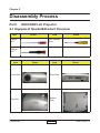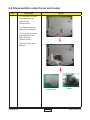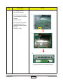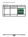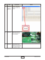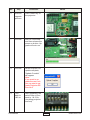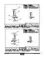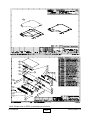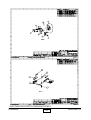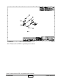
1
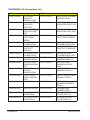
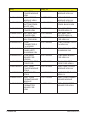
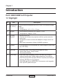
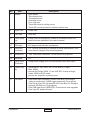
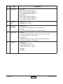
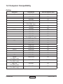
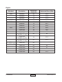
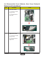
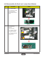
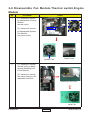
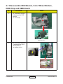
SERVICE MANUAL
Model Name : HD81/HD81-LV
Prepared by SI :
Vivian
________________________________________
Prepared by TSE :
________________________________________
Checked by :
________________________________________
Approved by :
Hank
________________________________________
Date
Version
Description
2006/08/14
V1.0
Initial Issue
2007/04/20
V2.0
Add HD81-LV
Modify Perface,Chapter 4,Chapter 5
2007/05/11
V3.0
2007/05/18
V4.0
2007/11/23
V5.0
Modify chapter 4 & 5
Modify chapter 1
Modify chapter 5
Copyright April, 2007 . All Rights Reserved 36.85H06G001
95.87T01GC0A
HD81&HD81-LV Comparison List
HD81
70.85H01G001
75.85H09G001
ASSY BASE
HOUSING
MODULE HD81
HD81-LV
70.87T01G001
ASSY BASE HOUSING
MODULE HD81-
75.87T06G001
BUY ASSY PREELEVATOR RIGHT HD
75.87T01G001
BUY ASSY PREELEVATOR LEFT HD8
70.87T05G001
ASSY ELEVATOR
FOOT RIGHT MODUL
51.83C21G011
ELEVATOR FOOT
PC+ABS BLACK HD8
ASSY ELEVATOR
FOOT LEFT MODULE
23.85H19G101
BUY ASSY PREELEVATOR
RIGHT HD
BUY ASSY PREELEVATOR LEFT
HD8
ASSY ELEVATOR
FOOT RIGHT
MODUL
ELEVATOR FOOT
PC+ABS EP910
ASSY ELEVATOR
FOOT LEFT
MODULE
ELEVATOR FOOT
PC+ABS EP910
BUY ASSY BASE
HOUSING HD81
ASSY OPTICAL
ENGINE MODULE
HD8
BUY ASSY
OPTICAL
MODULE HD81
ASSY COLOR
WHEEL MODULE
HD81
UNAXIS 56mm
52.85H11G001
SARCON GR-Hm
52.85H12G001
75.85H13G001
BUY ASSY REAR 75.87T07G001
COVER HD81
BUY ASSY RIGHT 75.87T05G001
COVER HD81
75.85H03G001
70.83C07G001
51.83C21G001
70.83C08G001
51.83C21G001
75.85H04G001
70.85H02G001
70.85H12G001
70.85H07G001
75.85H08G001
Confidential
70.87T06G001
51.83C21G011
75.87T02G001
70.87T09G001
70.87T10G001
ELEVATOR FOOT
PC+ABS BLACK HD8
BUY ASSY BASE
HOUSING HD81-LV
ASSY OPTICAL
ENGINE MODULE
HD8
ASSY OPTICAL
MODULE HD81-LV
70.87T11G001
ASSY COLOR WHEEL
MODULE HD81-L
23.87T19G001
56MM CW 5
SEGMENTS RGBCY
FOR H
ENGINE BASE
RUBBER HD81
BUY ASSY REAR
COVER HD81-LV
BUY ASSY RIGHT
COVER HD81-LV
HD81/HD81-LV
HD81
70.85H06G001
70.85H14G001
51.85H18G021
75.85H06G001
75.85H07G001
70.85H16G001
80.85H06G001
61.R0104G021
80.85H05G001
39.85H18G001
70.83C18G001
51.83C06G001
70.85H21G001
80.85H01G001
Confidential
ASSY TOP
COVER MODULE
HD81
ASSY KEYPAD
MODULE HD81
KEY PAD
BUTTON PEARL
WHITE HD8
BUY ASSY TOP
COVER HD81
BUY ASSY LEFT
COVER HD81
HD5000 VEDIO
BOX FOR HD81
PCBA
CONNECTOR-2
For HD5000
FRONT
PANEL(LEFT)
ALUMINUM “AN
PCBA MAIN
BOARD FOR
HD5000
FW 24LC02 EDID
CODE FOR
ASSY LAMP
COVER MODULE
EP910
LAMP COVER
EP910
ASSY PCBA
FORMAT BOARD
MODULE
PCBA
FORMATTER
BOARD FOR
HD81
HD81-LV
70.87T03G001
70.87T04G001
51.85H18G031
75.87T03G001
75.87T04G001
70.87T08G001
80.87T06G001
ASSY TOP COVER
MODULE HD81-LV
ASSY KEYPAD
MODULE HD81-LV
KEY PAD BUTTON
PEARL BLACK HD8
BUY ASSY TOP
COVER HD81-LV
BUY ASSY LEFT
COVER HD81-LV
HD5000 VEDIO BOX
FOR HD81-LV
PCBA CONNECTOR-2
For HD81-LV
61.R0104G041
FRONT PANEL(LEFT)
ALUMINUM “AN
80.87T05G001
PCBA MAIN BOARD
FOR HD81-LV
39.87T18G001
FW 24LC02 EDID
CODE FOR HD81-L
ASSY LAMP COVER
MODULE HD81-LV
70.87T07G001
51.83C06G021
70.87T12G001
80.87T01G001
LAMP COVER BLACK
HD81-LV
ASSY PCBA FORMAT
BOARD MODULE
PCBA FORMATTER
BOARD FOR HD81-
HD81/HD81-LV
Preface
This manual is applied to HD81/HD81-LV professional controller scaler and
color management system. The manual gives you a brief description of basic technical
information to help in service and maintain the product.
Your customers will appreciate the quick response time when you immediately
identify problems that occur with our products. We expect your customers will appreciate
the service that you offer them.
This manual is for technicians and people who have an electronic background.
Please send the product back to the distributor for repairing and do not attempt to do
anything that is complex or is not mentioned in the troubleshooting.
Notice:
The information found in this manual is subject to change without prior notice. Any
subsequent changes made to the data herein will be incorporated in future edition.
HD81/HD81-LV Service Manual
Copyright April, 2007
All Rights Reserved
Manual Version 2.0
P/N#36.85H06G001
Confidential
I
HD81/HD81-LV
Table of Contents
Chapter 1 Introduction
1-1
Part I HD81/HD81-LV Projector
1-1
Highlight
1-1
Computer Compatibility
1-5
Part II HD81/HD81-LV Controller Box
1-7
Highlight
1-7
Chapter 2 Disassembly Procedure
2-1
HD81/HD81-LV Projector � 2-1
Equipment Needed&Product Overview
2-1
Disassemble
������������������������������������������������������������������������������������
Lamp Cover and Lamp
2-2
Disassemble Focus Ring, Top Cover and Keypad Boar
2-3
Disassemble Cover Module, Rear Cover Network Module and Format
Board
2-5
Disassemble Air-Duct and Lamp driver Module
2-8
Disassemble Fan Module,Thermal switch,Engine Module
2-9
Disassemble IRIS Module, Color Wheel Module,DMD Chip and DMD
Board
2-11
Disassemble LVPS and Elevator Foot Module
���������������������������
2-13
HD81/HD81-LV Controller Box
2-14
Equipment
�������������������������������������������������������������������������������������������������
Needed
2-14
Disassemble
�������������������������������������������������������������������������
CONNT-2 Board, CONNT-1 Board,
Power Board and Main Board������������������������������������������������������������������������
2-15
Disassemble
�������������������������������������������
AC Plug, CONNT-3 Board, Keypad
Board and IR Board
2-18
Disassemble Geer Wheel, Front Cover, Left and
right Cover, front panel and Stamping Foot
Chapter 3 Troubleshooting
Confidential
2-20
3-1
Equipment Needed
3-1
Main procedure
3-2
II
HD81/HD81-LV
Chapter 4 Function Test and Alignment Procedure
4-1
HD81/HD81-LV��������������������������������������������������������������������������������
Projector
4-1
Test Equipment Needed
4-1
Test Condition
4-1
Inspection Procedure
4-4
HD81/HD81-LV��������������������������������������������������������������������������
Controller Box
4-8
Test Equipment Needed
4-8
Inspection Item
4-8
Inspection Procedure
4-8
Chapter 5 Firmware Upgrade Procedure
Main Board- Equipment Needed
5-1
5-1
HD81/HD81-LV���������������������������������������������������������������������������
Controller Box
5-2
Link MCU Upgrad
5-2
BOX MCU Upgrad
5-6
OSD Upgrad
5-9
Scaler Upgrad
5-12
RX Upgrad
5-15
TX Upgrad
5-19
HD81/HD81-LV�����������������������������������������������������������������������
Projector 5-23
MCU Upgrad
5-23
RX Upgrad
5-26
Chapter 6 EDID Upgrade Procedure
6-1
EDID Introduction
6-1
Equipment Needed
6-1
HD81/HD81-LV�����������������������������������������������������������������������������
Controller Box
6-2
HD81/HD81-LV��������������������������������������������������������������������������������
Projector
6-3
Appendix
7-1
Confidential
III
HD81/HD81-LV
Chapter 1
Introduction
Part I HD81/HD81-LV Projector
1-1 Highlight
No
Item
Description
1
Dimensions
(L* W* H)
- Unit(controller processor box): 433 x 285 x 50 mm(not include
hight
of feet)
- Unit(projector): 411 x 311 x 116 mm
2
Weight
- Unit(controller processor box): approx. 10 lbs
- Unit(projector): approx. 10 lbs
3
Cooling
System
- Advanced air flow
- One fan/ two blowers (in projector) with low system acoustic
noise level
- Temperature control circuits with adaptive voltage control fan
speed
- Max touch temperature follows UL60950 regulation
4
Cabinet
- Provides space for PCB boards, fan, optical engine, power sup
ply, UHP Lamp
5
Top Side
- Projection Lens Zoom Ring/Focus Ring/Lens Ring
- Three LEDs (Lamp, Temp, Power)
- Two elevator buttons
6
Rear Side
- One HDMI input connector (HDMI From Box) for linking to
“video processor box” HDMI output connector (To projector)
- One D-sub 9-pin RS-232 port (RS-232 From Box) for linking to
projector RS-232 port (To projector)
- One USB type-B port (SERVICE) for sequence code upgrade
- One 3-pin AC power inlet port
Confidential
1-
HD81/HD81-LV
No
Item
Description
7
Bottom
- Spec labels
- Two elevator foot
- Two adjuster foot
- One lamp cover
- Four-inlet vent
- Three M4 holes for ceiling mount
- Three M3 mounting holes for Navitar add-on lens
8
Right Side
- Outlet vent
9
Left Side
- Inlet vent
10
Lamp Housing
- Lamp could be changed by customer, but should follow the
instructions as indicated in the user’s manual
11
Tilt Angle
+5/-2 degree with elevator mechanism
12
Keystone
correction
- ± 5° Vertical (according to Gunnum’s scalar specification. Gen
num does not support Horizontal keystone)
13
Resolution
- True 1920x1080 resolution, 10 bits colors for projection
14
Materials
- PC
15
Lamp Door
Protection
- Lamp power supply shut off automatically when door open
16
Power Supply
- Universal AC 100--240V; 50 / 60 Hz with PFC input
- Max. 465W
- provide for Philips 300W 1.3 arc UHP E21.8 lamp at bright
mode, 255W at ECO mode
- provide for “projector” system power
17
Terminals
- One HDMI input connector (HDMI From Box) for linking to
“video processor box” HDMI output connector (To projector)
- One D-sub 9-pin RS-232 port(RS-232 From Box) for linking to
projector RS-232 port (To projector)
- One USB type-B port (SERVICE) for sequence code upgrade
- One 3-pin AC power inlet port
Confidential
1-
HD81/HD81-LV
No
Item
18
Input Signal
Spec.
- Analog RGB signal (PC)
Analog RGB 0.7Vp-p, 75 ohm
Analog RGB 1Vp-p, 75 ohm, Sync. signal
Separate TTL H,V Sync.
Composite TTL Sync.
- Video signal
Composite video 1Vp-p, 75 ohm
S-video Luminance 0.714Vp-p, 75 ohm
Chrominance 0.286Vp-p, 75 ohm
19
System
Controller
- De-interlace and Scalar: Gennum 10 bits GF 9351 scaler
- Color adjust chip: High-end Jepico L006 10 bit Image Quality
Enhancement LSI
20
Projection
Lens
- F/ 2.6~2.82, f = 39.12~46.94 mm. 1.2X Zoomed Focal Lens.
- Throw Ratio = 1.85 – 2.22:1 distance/width
- Offset : 136%
21
Throw Distance
1.85 – 2.22:1 distance/width
22
Brightness
For HD81
- 1400 ANSI Lumens (Max.)
- 1200 ANSI Lumens (Typical)
- 1000 ANSI Lumens (Min.)
For HD81-LV
- 2,500 ANSI Lumens (Max.)
- 1,800 ANSI Lumens-bright mode, 1,440 ANSI Lumens-ECO
mode (Typical)
- 1,440 ANSI Lumens (Min.)
23
Contrast
For HD81
- 7,000:1 full on/full off (with high contrast iris setting)
- 4,500:1 full on/full off (Max.)
- 3,500:1 full on/full off (Typical)
- 2,700:1 full on/full off (Min.)
For HD81-LV
- 10,000 :1 full on/full off (with high contrast iris setting)
- 3,600 :1 full on/full off (Max.)
- 3,000 :1 full on/full off (Typical)
- 2,400 :1 full on/full off (Min.)
Confidential
Description
1-
HD81/HD81-LV
No
Item
Description
24
Uniformity
For HD81
- 90% Japan standard (Max.)
- 85% Japan standard (Typical)
- 65% Japan Standard (Min.)
For HD81-LV
- 90% Japan standard (Max.)
- 75% Japan standard (Typical)
- 65% Japan Standard (Min.)
25
Temperature
- Operating: 5 -- 35°C
- Storage: -20 -- 60°C
26
Maximum
Humidity
- Operating:
5 -- 35°C, 80%RH (Max.), non-condensing
- Storage:
-20 -- 60°C, 80%RH (Max.), non-condensing
27
Lamp Life
For HD81
- 1700 hours typical, 50% survival rate in normal mode
- 2200 hours typical in Eco mode
For HD81-LV
- 1250 hours typical, 50% survival rate in bright mode
- 1600 hours typical in Eco mode
28
Altitude
- Operating
0~2,500 ft 5°C~35°C
2,500~5,000 ft 5°C~30°C
5,000~10,000 ft 5°C~25°C
- Storage
40,000 ft
Confidential
1-
HD81/HD81-LV
1-2 Computer Compatibility
Analog
Standard
Resolution
Vertical Refresh (Hz)
VGA
640x480
60
640x480
72
640x480
75
640x480
85
848x480
(For HD81 only)
720x400
60
720x400
85
800x600
56
800x600
60
800x600
72
800x600
(For HD81 LV only)
800x600
75
1024x768
60
1024x768
70
1024x768
75
1024x768
85
1280x768
60
1280x768
70
1280x768
75
HD
1280x720
60
SXGA
(For HD81 only)
MAC
(For HD81 only)�
MAC G4
(For HD81 only)
i Mac DV
(For HD81 only)�
1280x1024
60
1152x870
75.06
640x480
60
1024x768
75
SVGA
XGA
WXGA
Confidential
1-
70
85
HD81/HD81-LV
Digital
Standard
Resolution
Vertical Refresh (Hz)
Horizontal Scan (KHz)
VGA
640x480
60
31.5
640x480
72
37.9
640x480
75
37.5
US TEXT
720x400
70
31.5
SVGA
800x600
60
37.9
800x600
72
48.1
800x600
75
46.9
1024x768
60
48.4
1024x768
70
56.5
1024x768
75
60
60
45
24
27.0
60
67.5
XGA
1280x720
(ForHD81-LV only)
1920x1080
(ForHD81-LV only)
1920x1080
(ForHD81-LV only)
Wide
(For HD81 only)
Confidential
1280x720
50
1280x720
60
45
1920x1080
24
27
1920x1080
50
1920x1080
60
1-
67.5
HD81/HD81-LV
Part II HD81/HD81-LV Controller Box
1-3 Highlight
No Item
1
Cabinet
2
Color
3
Front Side
4
Power Consumption
5
Power supply
Confidential
Description
- Provides space for PCB boards, power supply, no need
of fans cooling
For HD81
- Top Cover: CS-CT108(Pearl white)
- Bottom Base: Pantone Cool Gray 9C (Glossy)
- Side/Back covers: CS-CT108( Pearl White)
- Lens rim/Zoom ring/Focus ring: Chromate treatment
- Keypad: CS-CT108( Pearl White)
For HD81-LV
- Top Cover: CS-CT112A(Pearl BLACK)
- Bottom Base:CS-CT54A (Black)
- Side/Back covers: CS-CT112A( Pearl BLACK)
- Lens rim/Zoom ring/Focus ring: Chromate treatment
- Keypad: CS-CT12A( Pearl BLACK)
- Seven controlled buttons of Power,Menu/Exit,Enter/
Source,Up,Down,Left,Right/Resync
- One LED (Standby:RED, Power on:Blue)
- One IR receiver window
- One Mini DIN 4-pin connector for S-video input
- One RCA Jack for Composite Video Input
- Push opened front cover with Gear
- Full power(at normal mode): typical 425W+/-10% at
110V AC
- ECO power(at ECO mode): typical 360W+/-10% at 110V
AC
- Standby mode: <7 W at 110V AC
- Universal AC 100--240V; 50 / 60 Hz with PFC input
- Max. 465W
- provide for “projector” system power
1-
HD81/HD81-LV
No Item
Description
6
Terminals
7
Analog input signal
spec
8
System Controller
- One D-sub 15-pin female connector for Component
video/Analog RGB input
- Two Mini DIN 4-pin connector for S-video input
- Two RCA Jack for Composite Video Input
- Two sets of RCA connectors (YPbPr) for Component
video input
- Two sets of BNC connectors (YPbPr/RGBHV) for Com
ponent video/Analog RGB input
- Two 12v trigger output connector for projector screen
control
- One D-sub 9-pin RS-232 port (For control) connecting to
computer for projector control/FW upgrade
- Three HDMI input connector (HDMI in-1,HDMI in-2,HDMI
in-3) for HDMI device source switching
- One HDMI output connector (To AV receiver) for con
necting to AVR device HDMI input port
- One HDMI input connector(From AV receiver) for con
necting form AVR device HDMI output port
- One HDMI output connector (To projector) for linking to
projector HDMI input port (HDMI From Box)
- One D-sub 9-pin RS-232 port (To projector) for linking to
projector RS-232 port (RS-232From Box)
- One earphone jack (IR Module) for external IR receiver
module
- One 2-pin AC power inlet port
- Analog RGB signal(PC)
Analog RGB 0.7Vp-p, 75 ohm
Analog RGB 1Vp-p, 75 ohm, Sync. signal
Separate TTL H,V Sync.
Composite TTL Sync.
- Video signal
Composite video 1Vp-p, 75 ohm
S-video Luminance 0.714Vp-p, 75 ohm
Chrominance 0.286Vp-p, 75 ohm
- Dual DDP3021, DAD1000, PMD1000 for 1080p DMD
9
Video Compatibility
10
Keystone correction
Confidential
- Standards:
NTSC - NTSC M/J, NTSC 4.43
PAL - PAL B/D/I/G/H, PAL M, PAL N
SECAM - SECAM B/D/G/K/L
SDTV - 480i, 480p, 576i, 576p,
HDTV - 720p(50Hz), 720p(60Hz), 1080i(50Hz),
1080i(60Hz), 1080p (60Hz)
- ± 5° Vertical(according to Gunnum’s scalar specification.
Gennum does not support Horizontal keystone)
1-
HD81/HD81-LV
No Item
Description
11
Auto Detect & Install
12
LED Indicators
13
Control Key Pad
14
On-Screen Menu
- Automatically recognizes the input signal and configures
Itself accordingly.
- Automatically saves adjustments for future use. Saved
settings provide a method to
quickly identify previously configured modes and restore
those settings
- Lower brightness of “Power LED” (Blue) after turn on the
power button 5 min.
7 button keys:
- Power button: power on/off
- Menu/Exit button: menu or exit
- Enter/Source button: enter or select next input source
signal
- Left button: ‘left’ when OSD menu activated or source
- Right/Resync button: ‘right’ when OSD menu activated or
re-sync. Input source signal
- Down button: ‘down’ when OSD menu activated
- Up button: ‘up’ when OSD menu activated
- OSD Languages: English, German, French, Italian,
Spanish, Portuguese, Polish, Dutch, Swedish, Norwegian
(No/Dk), Russian,Finnish, Traditional Chinese, Simplified
Chinese, Japanese, Korean: 16 in total.
15
OSD menu
Confidential
- Lamp life, lamp output control. Core: okay
- DDP3021 controls.
- Projection positions. Core: okay
- CCA control via DDP3021
- Brilliant color control.
1-
HD81/HD81-LV
Chapter 2
Disassembly Process
Part I
HD81/HD81-LV Projector
2-1 Equipment Needed&Product Overview
Item
Photo
Item
Photo
Hex Sleeves
5mm
Philips:
107
Philips:
101
Item
Photo
Item
Front Side
Rear Side
Top Side
Bottom
Side
Confidential
2-
Photo
HD81/HD81-LV
2-2 Disassemble Lamp Cover and Lamp
No
1
Procedure
(1). Unscrew 2 screws
to disassemble the
Lamp Cover.
(as red circle)
Photo
1
(2). Disassemble the
Lamp Cover Module.
(3). Unscrew 2 screws
to disassemble the
Lamp Module.
(as pink circle)
(4).Pull up the Lamp
Module.
2
Lamp Cover
Confidential
2-
Lamp
HD81/HD81-LV
2-3 Disassemble Focus Ring,Top Cover&Keypad Board
No
Procedure
1
(1). Unscrew 13 screws
from the Bottom Cover.
(as red circle)
Photo
1
(2). Unscrew 2 screws
from the Rear Cover.
(as red circle)
(3). Disassemble Focus
Ring, unplug the wire
(as yellow square) and
push forward to disassemble the Top Cover.
2
3
Focus Ring
Note:HD81 is white
HD81-LV is black
Top Cover
Note:HD81 is white
HD81-LV is black
Confidential
2-
HD81/HD81-LV
No
2
Procedure
Photo
(1). Unplug 1 wire.
(as yellow square)
(2). Unscrew 4 screws
to disassemble Keypad
Module.
(as red circle)
1
(3). Unscrew 2 screws
to disassemble Keypad Board and Keypad
Bracket.
(as blue circle)
2
3
Keypad Board and Keypad Bracket
Confidential
2-
HD81/HD81-LV
2-4 Disassemble Cover Module, Rear Cover Network
Module and Format Board
No
1
Procedure
Left cover module:
Photo
1
(1). Unscrew 1 screw.
(as red circle)
(2). Disassemble the
Left cover.
2
Left Cover Module
2
Right cover module:
(1). Unscrew 2 screws.
(as red circle)
(2). Disassemble the
Right cover.
Right Cover Module
Confidential
2-
HD81/HD81-LV
No
3
Procedure
Photo
Rear Cover:
(1). Unscrew 1 screw
and 2 Hexes to disassemble Rear Cover.
Rear Cover
Note:HD81 is white
HD81-LV is black
4
Network Module:
(1). Unscrew 2 screws.
(as red circle)
(2). Unplug 2 wires.
(as yellow square)
(3). Disassemble Network Module.
Network Module
Confidential
2-
HD81/HD81-LV
No
5
Procedure
Photo
Format Board:
(1). Unscrew 2 screws.
(as red circle)
(2). Unscrew 2 copper
pillars.
(as green circle)
(3). Unplug 7 wires.
(as yellow square)
(4). Disassemble Format Board
Note: Please take note
of the matching of wire
connection
Format Board
Confidential
2-
HD81/HD81-LV
2-5 Disassemble Air-Duct and Lamp driver Module
No
1
Procedure
Photo
(1). Tear the tape.
(2). Unscrew 1 screw
(as red circle) to
disassemble the AirDuct.
Air-Duct
2
(1). Unscrew 3
screws.
(as red circle)
(2). Unplug 2 plugs.
(as yellow square)
(3). Disassemble the
Lamp driver.
Lamp driver
Confidential
2-
HD81/HD81-LV
2-6 Disassemble Fan Module,Thermal switch,Engine
Module
No
Procedure
1
(1). Unscrew 3 screws
to disassemble Cooling
Module.
(as red circle)
Photo
(2). Unscrew 4 screws
to disassemble System
Fan Module.
(as yellow circle)
System Fan
2
Metal Cover
(1). Unscrew 3 screws
(as red circle) to disassemble Shielding Left
Cover Module
(2). Unscrew 3 screws
(as yellow circle) to disassemble Axial Fan.
Shielding Left Cover
Axial Fan
Confidential
2-
HD81/HD81-LV
No
Procedure
3
Unscrew 3 screws (as
red circle) and 1 copper
pillars (as green circle)
to disassemble Engine
Module.
Photo
Engine Module
4
1. Unscrew 2 screws.
(as red circle)
2. Disassemble Fan
Module.
Fan Module
Confidential
2-10
HD81/HD81-LV
2-7 Disassemble IRIS Module, Color Wheel Module,
DMD Chip and DMD Board
No
Procedure
1
(1). Unscrew 1 screw
to disassemble IRIS
Module.
(as red circle)
Photo
IRIS Module
2
(1). Unscrew 2 screws
to disassemble Color
Wheel Module.
(as yellow circle)
Color Wheel Module
Confidential
2-11
HD81/HD81-LV
No
Procedure
2
(2). Unscrew 1 screw
to disassemble Color
Wheel and photo sensor.
(as red circle)
Photo
Note: Avoid to touch
the glass parts in
Color Wheel.
photo sensor
3
Color Wheel
(1). Unscrew 4
screws.
(as red circle)
(2). Disassemble
DMD Chip and DMD
Board.
DMD Chip and DMD Board
Confidential
2-12
HD81/HD81-LV
2-8 Disassemble LVPS and Elevator Foot Module
No
1
Procedure
Photo
(1). Unscrew 1 screw
(as red circle) and 2
copper pillars.
(as green circle)
(2). Unplug 1 wire.
(as yellow square)
(3). Lift up the LVPS.
LVPS
2
Unscrew 6 screws to
disassemble Elevator
Foot Module both left
and right side.
Elevator Foot
Module
Confidential
2-13
HD81/HD81-LV
Part II HD81/HD81-LV Controller Box
2-1 Equipment Needed
Item
Photo
Item
Screw Bit
(+) :107
Hex Sleeves
5mm
Hex
Sleeves
6mm
Hex Socket
Insert Bit
Confidential
2-14
Photo
HD81/HD81-LV
2-2 Disassemble CONNT-2 Board, CONNT-1 Board,
Power Board and Main Board
No
1
Procedure
Photo
(1). Press the part (in the
red square) to open Front
Cover.
(2). Unscrew 8 Hex Socket
Cap Screws to disassemble
Top Cover.
Press to open front cover
Top Cover
2
Unscrew 4 screws (in the
red circle) and 4 hex screws
(in the green circle) to disassemble CONNT-2 Board.
CONNT-2 Board
Confidential
2-15
HD81/HD81-LV
No
3
Procedure
Photo
Unscrew 2 screws to
disassemble
CONNT-1 Board.
CONNT-1 Board
4
Unscrew 4 screws (in the red
circle) and unplug 2 connectors (in the green square) to
disassemble Power Board.
Power Board
Confidential
2-16
HD81/HD81-LV
No
Procedure
5
Unscrew 3 screws (red circle), 6 copper pillars (yellow
circle and unplug 4 connectors (red square) to disassemble Main Board and
Back End Metal.
Photo
Main Board
Confidential
2-17
HD81/HD81-LV
2-3 Disassemble AC Plug, CONNT-3 Board, Keypad Board
and IR Board
No
1
Procedure
Photo
Unscrew 3 screws
to disassemble AC
Plug.
AC Plug
2
Unscrew 2 screws
(in the red circle) and
2 hex screws (in the
green circle) to disassemble CONNT-3
Board and Back End
Metal.
CONNT-3 Board
Confidential
2-18
Back End Metal.
HD81/HD81-LV
No
3
Procedure
Photo
Unscrew 6 screw
nuts to disassemble
Keypad Board.
Keypad Board
4
Unscrew 1 screw and
tear the masking tape
to disassemble IR
Board.
IR Board
5
Disassemble Mylar
Mylar
Confidential
2-19
HD81/HD81-LV
2-4 Disassemble Geer Wheel, Front Cover, Left and right
Cover, front panel,Door Lock and Stamping Foot
No
Procedure
1
Unscrew 1 screws
to disassemble Gear
Wheel.
Photo
Gear Wheel
2
Unscrew 3 screws to
disassemble Right
and Left Front Panel.
Screw
Hex I/O
3
Right Front
Panel
Left Front
Panel
Unscrew 2 screws
(in the red circle) to
disassemble the Door
Lock.
Door Lock
Confidential
2-20
HD81/HD81-LV
No
Procedure
4
Unscrew 8 screws
(in the left and right
side respectively) to
disassemble Left and
Right Lateral Panel.
Photo
Left and Right Lateral Panel
5
Unscrew 7 screws to
disassemble Front
Panel.
Front Panel
Confidential
2-21
HD81/HD81-LV
No
Procedure
6
Unscrew 4 screws to
disassemble Stamping Foot.
Photo
Stamping Foot
Confidential
2-22
HD81/HD81-LV
Chapter 3
Troubleshooting
3-1 LED Lighting Message
HD81/HD81-LV’s Projector side
Normal Operation
Message
Power LED
Red
Dark
Blue
Lamp-LED
Bright
Blue
Orange
Blue
Temp-LED
Red
Blue
Standby State
(Input power
cord)
Power on (warming)
Dark LED for cinema (After Power
on 5 mins.)
Power off (Cooling)
Blinking
Error (Lamp fail)
Blinking
Error (Fan fail)
Blinking
Error (Over
Temp.)
Error (HDMI Connection Fail (*2))
Blinking
Error (RS232
Connection Fail
(*2))
Confidential
Blinking
3-
HD81/HD81-LV
HD81/HD81-LV’s Box
Normal Operation
Message
Power LED
Red
Bright Blue
Standby State
(Input power cord)
Power on
=> Light On
Confidential
=> Light Off
3-
HD81/HD81-LV
No
Symptom
Procedure
4
No Light On
-
5
Mechanical Noise
- Check Color Wheel
- Check Fan Module
6
Line Bar / Line
Defect
- Check if the Main Board and the DMD Board are
assembled properly
- Check DMD Board
- Check DMD Chip
- Check Format Board
7
Image Flicker
- Do “Reset” of the OSD Menu
- Ensure the Signal Cable and Source work
- Clean Photo Sensor Board
- Check Format Board
- Check Color Wheel
- Check DMD Board
- Check Main Board
8
Color Abnormal
- Do “Reset” of the OSD Menu
- Adjust Color Wheel Index
- Check Main Board
- Check DMD Board
- Check Color Wheel
9
Poor Uniformity /
Shadow
- Ensure the Projection Screen without dirt
- Ensure the Projection Lens is clean
- Ensure the Brightness is within spec.
(Replace the Lamp if the Brightness is less than spec.)
- Check Engine Module
10
Dead Pixel / Dust
(Out of spec.)
- Ensure the Projection Screen without dirt
- Ensure the Projection Lens is clean
- Clean DMD Chip and Engine Module
- Check DMD Chip
- Check Engine Module
Confidential
Ensure all connectors are securely connected and aren’t
broken
- Check Lamp Module
- Check lamp driver
- Check LVPS
- Check Main Board
- Check IO Board
- Check format Board
- Check connector-1 Board
3-
HD81/HD81-LV
No
Symptom
Procedure
11
Remote Control
or Control Panel
Failed
- Remote Control
a. Check Battery
b. Check Remote Control
c. IR Receiver
d. Check Main Board
- Control Panel
a. Check FPC
b. Check Keypad
c. Check Main Board
12
Function Abnormal
- Do “Reset” of the OSD Menu
- Check Main Board
- Check format Board
- Check Auto IRIS(If IRIS function failed)
13
Sound Abnormal
- Ensure the AV-Recevier connector is correctly
connected
- Ensure the Signal Cable and Source work
- Check Speaker
- Check Main Board
- Check Connect Board
14
Rod Adjustment
- If there are shadow at “TOP” & “Bottom”side of the
screen, adjust “Screw 1” to adjust ROD position
- If there are shadow / yellow light / blue light at “Left” &
“Right” side of the screen, adjust “Screw 2” to adjust
ROD position
- “Screw 1” should be adjusted first, and then “Screw
2”
Screw 2
Screw 1
Confidential
3-
HD81/HD81-LV
3-2 Main Procedure
No
Symptom
Procedure
1
No Power
- Ensure the Power Cord and AC Power Outlet are
securely connected
- Check Lamp Cover and Interrupt Switch
- Ensure all connectors are securely connected and aren’t
broken
a. Projector and controller Box’s LED are both no light
- Check Box’s Power Board
- Check Box’s Main Board
b. Projector LED no light, controller Box LED normal
- Check controller’s connector-1 Board
- Check projector IO Board
2
Auto Shut Down
Do reset of the controller Box
- Check LED Status
a. Lamp LED Light
- Check Lamp
- Check Lamp Driver
- Check Format Board
b. Temp LED Light
- Check Thermal Sensor
- Check Thermal Switch
- Check Fan
c. Color Wheel
- Check Color Wheel
- Check Photo Sensor
3
No Image
- Ensure the Signal Cable and Source work as well
(If you connect multiple sources at the same time, use
the “Source” button on the control panel to swtich)
- Ensure all connectors are securely connected and aren’t
broken
Do system reset of menu
- Check Main Board
Confidential
3-
HD81/HD81-LV
3-3 System Block Diagram
HD81/HD81-LV Projector
Confidential
3-
HD81/HD81-LV
HD81/HD81-LV Video Box
Confidential
3-
HD81/HD81-LV
Chapter 4
F u n c t i o n Te s t & A l i g n m e n t
Part I
HD81/HD81-LV Projector
4-1 Test Equipment Needed
- IBM PC with XGA resolution (Color Video Signal & Pattern Generator)
- DVD player with Multi-system (NTSC/PAL/SECAM)
- HDTV Tuner or Source (480i, 720P, 1080i), equipped with “Component”, “S-Video”,
“Composite” Interface.
- Minolta CL-100
- Quantum Data 802B or CHROMA2327
- After changing parts, check the information below. It needs the Controller Box.
Charge
Parts/
Update
Version
Update
Color
Wheel
Index
M/B
v
v
v
FW
v
v
v
Color
Wheel
ADC
Calibration
Video
Calibration
Reset
Lamp
Use Time
Factory
Reset
EDID
Lamp
life
v
v
Lamp
Module
v
4-2 Service Mode
No
Step
1
Turn on the Projector and controller Box and input the signal.
2
Do the following action sequentially to enter service mode menu.
(1) Press and hold these button sequentially
(2) Service Mode will be shown after pressing
for 3 seconds.
(3) After confirming the configuration, press “Menu” and exit.
Confidential
4-
HD81/HD81-LV
4-3 Reset(OSD)
No
1
Step
After final QC step, we have to erase all saved change again and restore the
OSD default setting.The following actions will allow you to erase all end-users’
settings and restore the original setting:
(1) Please enter OSD menu.
(2) To execute “Reset” function .
4-4 Test Condition
- Circumstance Brightness : Dark room less than 10 lux.
- Inspection Distance : 1.7m~2.4m for functional inspection
- Screen Size : 60 inches diagonal (wide)
- After repairing each HD81&HD81-LV, the unit should be run-in (Refer to the table below).
Symptom
Run-in Time
Normal Repair
2 Hours
NFF
4 Hours
Auto Shutdown
6 Hours
- Enter Burn-In Mode
* Cycle setting is based on the defect symptoms. ie: If it is NFF, the run-in time is 4 hours.
You have to set the lamp on for 50min. and lamp off for 10 min for 4 cycles.
Confidential
4-
HD81/HD81-LV
Press Down > Down > Left > Left
Choose Burn-In Test > enter
Lamp On (Min)
Press right key to adjust the time (50)
Lamp Off (Min)
Press right key to adjust the time (10)
Set burn in cycle
Press right key to adjust the cycle
After setting up the time, choose Burn-In mode and hit enter
Screen Defects (While replacing DMD Chip, DMD BD and MB)
< Figure: Zone A & B Definition >
Confidential
4-
HD81/HD81-LV
4-5 Inspection Procedure
No
Step
Specification
Procedure
1
Frequency
and Tracking
Eliminate visual
wavy noise by
Rsync, Frequency or Tracking
selection.
- Test Signal :
1920x1080@60Hz
- Test Pattern :
Line Moire Pattern
- check and see if
image sharpness
and focus are wellperformed.
- If not, re-adjust by
the followingsteps:
(1) Select “Frequency” function to adjust
the total pixel
number of pixel
clock in one line
period.
(2) Then, select
“Tracking” function and use
right or left
arrow key to
adjust the value
to minimize
video flicker.
2
Boundary
Horz. And Vert.
position of
video should be
adjustable to
be the screen
frame.
- Test Signal :
1920x1080@60Hz
- Test Pattern :
Flare-w Pattern
- Adjust Resync or
Frequency / Track
ing / H. Position /
V. Position to the
inner of the screen.
Confidential
4-
Photo
HD81/HD81-LV
No
Step
Specification
Procedure
3
Focus
The text in the
corner should be
clear after adjust
the focus ring.
- Test Signal :
1920x1080@60Hz
- Test Pattern :
Text Pattern
- Adjust the center
clearly; meanwhile,
one slightly vague
corner in the image
is allowed.
4
Color
Performance
No image
(discolor)
- Test Signal :
1920x1080@60Hz
- Test Pattern :
64 RGBW Scale
Pattern & Gray 16
Pattern
- Please check and
ensure if each
color is normal and
distinguishable.
- If not, please
adjust color index
of the Engineering
Mode.
5
Screen
Uniformity
Should be
compliant with
60%.(Minimum)
- Test Signal :
1920x1080@60Hz
- Test Pattern :
Full White Pattern
Confidential
4-
Photo
HD81/HD81-LV
No
Step
Specification
Procedure
5
Screen
Uniformity
Should be
compliant with
60%.(Minimum)
- Please check and
ensure the unit is
under the spec.
- Please check and
see if it’s in normal
condition.
- If not, please
return the unit to
repair area.
6
Light Leak
The unit can’t
accept the leakage is brighter
then Gary 10
pattern
- Test Signal :
1920x1080@60Hz
- Test Pattern :
Gray 10 Patterns
- Please check and
see if the light
leaks *Note
- The unit cannot
accept the leakage
is brighter
than Gray 10
Patterns
Note:
Light leak on
reflective edge,
eyecatcher, bond
wires and exposed
metal.
Confidential
4-
Photo
HD81/HD81-LV
No
Step
7
Dead Pixel
(Bright pixel)
Cannot accept
any bright pixel
- Test Pattern :
Full Black
Dead Pixel
(Dark pixel)
The numbers
of dead pixel
should be smaller or amount to
6 pixels.
- Test Pattern :
Full White
8
Blemish
(Bright)
The bright blemish cannot be
accepted if the
problem appear
with Gary 30
patterns
- Test Pattern :
Full Black /
Gray 30
9
Blemish
(Dark)
The dark blemish cannot be
accepted if the
problem appear
with Blue 60
patterns
- Test Pattern :
Full white / Blue 60
Confidential
Specification
Procedure
4-
Photo
HD81/HD81-LV
Part II HD81/HD81-LV Controller Box
4-1 Test Equipment Needed
- Display Device (ex: Projectors)
- Signal Source (HDMI, Video, S-Video)
- Speaker
- PC
Note: Do the test procedure it needs the projector.
4-2 Inspection Item
No
Item
1
- Image
HDMI 1&2&3, S-Video 1&2&3, CVBS 1&2&3,
YPbPr 1&2, VGA, BNC 1&2
2
- Sound
Speaker
3
- Remote Control
4-3 Inspection Procedure
No
Step
1
- Connect all source
RS232,HDMI
2
- Switch input source by Remote Control and Control Panel.
- Check if Image is normal.
Get into service mode (Box)
(Hot key to get into service mode:
press these button sequentially , ,
,
)
Get into service mode (Projector)
(Hot key to get into service mode:
press these button sequentially , ,
,
)
Select projector -- into projector mode.
3
Region code setting:
press these button sequentially , ,
,
)
Select projector -- into projector mode.
Then, select “region select”
Confidential
4-
HD81/HD81-LV
Chapter 5
Firmware Upgrade Procedure
5-1 Main Board- Equipment Needed
Software
-
Upgrade AP HD81(1.3).rar
-
*.H00 (hix file)
-
*.H01 (hix file)
-
Device (*.bin file)
Hardware
-
HD81/HD81-LV and power cord
-
PC
-
RS 232 9 pin cable (pin to pin)
Item
HD81
Projector
Photo
Item
Photo
RS-232
Cable
(M to M)
PN: 42.86603G001
For box
PC
Power
Cord
For projector
Confidential
5-
HD81/HD81-LV
Part I HD81/HD81-LV Controller Box
5-2 Link MCU Upgrade (Location: U6)
Setup Procedure
No
Step
Procedure
1
Connect All Ports
Connect RS232 cable
from Controller Box to
PC.
2
Main Board switch
setting
(control box)
Set switch to1& 2 On.
Location: SW1
3
Unplug in the power
cord into the control
box
Confidential
5-
Photo
HD81/HD81-LV
Upgrade Procedure
No
Step
Procedure
1
Execute
UpgradeHD81.exe
Program
Double Click “UpgradeHD81” Program.
2
Setting
1. Select com Port
to your real connection port number.
Photo
2. Select Device to
“link” .
3. Select link to
the upgrade file:
TP2808.H00.
Note:
*.H00 and *.H01
must be in the
same folder.
(3)
(1)
(2)
Confidential
5-
HD81/HD81-LV
No
Step
3
Execute
upgrade
process
Press “Download”
button to start upgrade.
3.1
link
RS232
cable
Link PC and control
box by pluging the
RS232 cable to PC
and “for control” port
on the control box
4
Unplug
power
cord
Make sure power
cord unplug.
5
Press
Hot key
for upgrade
Press and hold the
left key on front
panel.
Confidential
Procedure
Photo
5-
HD81/HD81-LV
No
Step
Procedure
6
Plug
power
cord
Plug the power cord.
7
Process
Wait for 5 seconds,
then release left key.
Upgrade will auto
run.
8
Upgrade
finish
When MCU update
complete, “Update
Complete” will appear.
Photo
Note:
If you want to upgrade the next unit,
you can start to
upgrade MCU from
No.3
Confidential
5-
HD81/HD81-LV
5-3 BOX MCU Upgrade (Location: U126)
Setup Procedure
No
Step
Procedure
1
Connect All Ports
Connect RS232 cable
from Controller Box to
PC.
2
Main Board switch
setting
(control box)
Set switch to 1& 2 On.
3
Unplug in the power
cord into the control
box
Confidential
5-
Photo
HD81/HD81-LV
Upgrade Procedure
No
Step
Procedure
1
Execute
UpgradeHD81.exe
Program
Double Click “UpgradeHD81” Program.
2
Setting
1. Select com Port
to your real connection port number.
Photo
2. Select Device to
“MCU“ .
3. Select MCU to
the upgrade file:
HD5000.H00.
(3)
Note:
*.H00 and *.H01
must be in the
same folder.
(1)
(2)
Confidential
5-
HD81/HD81-LV
No
Step
3
Execute
upgrade
process
Press “Download”
button to start upgrade.
4
Unplug
power
cord
Make sure power
cord unplug.
5
Press
Hot key
for upgrade
Press and hold the
left key on front
panel.
Confidential
Procedure
Photo
5-
HD81/HD81-LV
No
Step
Procedure
Photo
6
Plug
power
cord
Plug the power cord.
7
Process
Wait for 5 seconds,
then release left key.
Upgrade will auto
run.
8
Upgrade
finish
When MCU update
complete, “Update
Complete” will appear.
Note:
If you want to upgrade the next unit,
you can start to
upgrade MCU from
No.3
5-4 OSD Upgrade (Location: U35, U36, U37, U38)
Setup Procedure
No
Step
Procedure
1
Connect All Ports
Connect RS232 cable
from Video Main Board
to PC.
2
Main Board switch
setting
Set switch to1& 2 On.
3
Plug in the the
power cord into the
control box
Confidential
5-
Photo
HD81/HD81-LV
Upgrade Procedure
No
Step
Procedure
1
Execute
UpgradeHD81.exe
Program
Double Click “UpgradeHD81” Program
2
Setting
1. Select com Port
to your real connection port number.
Photo
2. Select Device
to “OSD1”.
And then
“OSD2”,“OSD3”
and “OSD4” will
auto load in.
3. Select OSD to
the upgrade file:
U35 Device1.bin.
And then
U36 Device2.bin
U37 Device3.bin
and U38 Device4.
bin will auto load in
(3)
(2)
(1)
Confidential
5-10
HD81/HD81-LV
No
Step
Procedure
3
Setting
Unplug power cord
and then plug in
power cord. Make
sure the led in front
panel is red.
4
Execute
upgrade
process
Press “Download”
button to start upgrade.
5
Process
Wait for 5 seconds,
the upgrade will auto
run.
6
Upgrade
finish
When OSD update
complete (about 20
minutes), “Update
Complete” will appear.
Photo
Note:
If you want to upgrade the next unit,
you can start to
upgrade OSD from
No.3
Confidential
5-11
HD81/HD81-LV
5-5 Scaler Upgrade (Location: U33, U34)
Setup Procedure
Note:When upgrade the Scaler,please keep the power on .(If the power cut off,it must
change IC U33,U34 )
No
Step
Procedure
1
Connect All Ports
Connect RS232 cable
from Controller Box to
PC.
2
Main Board switch
setting
(control box)
Set switch to 1& 2 On.
3
Plug in the power
cord into the control
box
Confidential
5-12
Photo
HD81/HD81-LV
Upgrade Procedure
No
Step
Procedure
1
Execute
UpgradeHD81.exe
Program
Double Click “UpgradeHD81” Program.
2
Setting
1. Select com Port
to your real connection port number.
Photo
2. Select Device to
“Scaler”.
3. Select Box to the
upgrade file, U33
Devies5.bin. And
then U34 Devies5.
bin will auto load in
(3)
(2)
(1)
Confidential
5-13
HD81/HD81-LV
No
Step
Procedure
3
Process
Unplug the power
cable of Controller box and plug-in
power to Controller
box again. Please
check the Led on
Controller box front
panel is red.
4
Execute
upgrade
process
Press “Download”
button to start upgrade.
5
Process
Upgrade will auto run
after 5 seconds.
6
Upgrade
finish
When Scaler update
complete, “Update Comlete” will appear.
Photo
Note:
If you want to upgrade
the next unit, you can
start to upgrade Projector
RX from No.4
Confidential
5-14
HD81/HD81-LV
5-6 RX Upgrade (Location: HDMI RX U132)
Setup Procedure
No
Step
Procedure
1
Connect All Ports
Connect RS232 cable
from Controller Box to
PC.
2
Main Board switch
setting
Set switch to 3& 4 On.
3
Plug in the power
cord into the control
box
Confidential
5-15
Photo
HD81/HD81-LV
Upgrade Procedure
No
Step
Procedure
1
Execute UpgradeHD81.
exe Program
Double Click
“UpgradeHD81” Program.
2
Setting
1. Select com
Port to your
real connection port number.
Photo
2. Select Device to “RX”.
3. Select Box
to the upgrade
file:(HDMI_RX
Rev......)
TP2808.H00.
Note:
*.H00 and
*.H01 must be
in the same
folder.
(3)
(1)
Confidential
5-16
(2)
HD81/HD81-LV
No
Step
3
Execute
upgrade
process
Press “Download”
button to start upgrade.
4
Process
Unplug the power
cable of Controller box and Plug-in
power to Controller
box again.
5
Process
Push and hold the
button, ISP.(TX&RX),
near the switch.(on
the control box)
6
Process
Push Up key and
Down key at the
same time. Check
the Led is blue.
Confidential
Procedure
Photo
5-17
HD81/HD81-LV
No
Step
Procedure
Photo
7
Process
Wait for 5 seconds,
and then release button, ISP (TX& RX).
Upgrade will auto
run.
8
Upgrade
finish
When Controller box
RX update complete,
“Update Complete”
will appear.
Note:
If you want to upgrade the next unit,
you can start to upgrade Box RX from
No.3
Confidential
5-18
HD81/HD81-LV
5-7 TX Upgrade (Location: U167)
Setup Procedure
No
Step
Procedure
1
Connect All Ports
Connect RS232 cable
from Controller Box to
PC.
2
Main Board switch
setting
Set switch to 5& 6 On.
3
Plug in the power
cord into the control
box
Confidential
5-19
Photo
HD81/HD81-LV
Upgrade Procedure
No
Step
Procedure
1
Execute UpgradeHD81.
exe Program
Double Click
“UpgradeHD81” Program.
2
Setting
1. Select com
Port to your
real connection port number.
Photo
2. Select Device to “TX”.
3. Select
Box to the
upgrade file:
(HDMI TX......)
TP2808.H00.
Note:
*.H00 and
*.H01 must be
in the same
folder.
(3)
(2)
(1)
Confidential
5-20
HD81/HD81-LV
No
Step
3
Execute
upgrade
process
Press “Download”
button to start upgrade.
4
Process
Unplug the power
cable of Controller box and Plug-in
power to Controller
box again.
5
Process
Push and hold the
button, ISP(TX&RX),
near the switch.
(on the control box)
6
Process
Push Up key and
Down key at the
same time about 5
seconds and then release the up& down
key. Check the Led
is blue.
Confidential
Procedure
Photo
5-21
HD81/HD81-LV
No
Step
Procedure
7
Process
Wait for 5 seconds,
and then release
button, ISP(TX&RX).
Upgrade will auto
run.
8
Upgrade
finish
When Controller box
TX update complete,
“Update Comlete”
will appear.
Photo
Note:
If you want to upgrade the next unit,
you can start to upgrade Box RX from
No.3
Confidential
5-22
HD81/HD81-LV
Part II HD81/HD81-LV Projector
5-1 MCU Upgrade (Location: U25)
Setup Procedure
No
Step
Procedure
1
Connect All Ports
Connect RS232 cable
from Projector to PC.
2
Main Board switch
setting
Set switch to 1& 2 On.
Location: SW1
(on the projector formatter board)
3
Plug in the the
power cord into the
projector
Confidential
5-23
Photo
HD81/HD81-LV
Upgrade Procedure
No
Step
Procedure
1
Execute UpgradeHD81.
exe Program
Double Click
“UpgradeHD81” Program.
2
Setting
1. Select com
Port to your
real connec
tion port num
ber.
Photo
2. Select Device to “MCU”.
3. Select MCU
to the upgrade
file:
(main MCU ...)
H81C03.H00.
(2)
(3)
(1)
Confidential
5-24
HD81/HD81-LV
No
Step
3
Execute
upgrade
process
Press “Download”
button to start upgrade.
4
Process
Unplug the power
cable of HD81 projector.
5
Process
Push and hold the
button(ISP_DL) on
format board.
(projector)
Confidential
Procedure
Photo
5-25
HD81/HD81-LV
No
Step
Procedure
6
Setting
Plug-in power to
HD81 box.
7
Process
Wait for 5 seconds,
then release left key.
Upgrade will auto
run.
8
Upgrade
finish
When MCU update
complete, “Update
Complete” will appear.
Photo
Note:
If you want to upgrade the next unit,
you can start to
upgrade MCU from
No.3
Confidential
5-26
HD81/HD81-LV
5-2 RX Upgrade (Location: U8)
Setup Procedure
No
Step
Procedure
1
Connect All Ports
Connect RS232 cable
from Projector to PC.
2
Main Board switch
setting
Set switch 3& 4 On.
3
Plug in the power
cord
Confidential
5-27
Photo
HD81/HD81-LV
Upgrade Procedure
No
Step
Procedure
1
Execute UpgradeHD81.
exe Program
Double Click
“UpgradeHD81” Program.
2
Setting
1. Select com
Port to your
real connec
tion port num
ber.
Photo
2. Select Device to “RX2”.
3. Select Projector to the
upgrade file:
(HDMI_RX2...)
C01.H00.
(3)
Note:
*.H00 and
*.H01 must be
in the same
folder.
(1)
(2)
Confidential
5-28
HD81/HD81-LV
No
Step
3
Execute
upgrade
process
Press “Download”
button to start upgrade.
4
Process
Push and hold the
ISP_DL button on
the I/O board.
5
Process
Unplug the power
cable of the projector
and Plug-in power to
the projector again.
Confidential
Procedure
Photo
5-29
HD81/HD81-LV
No
Step
6
Execute
upgrade
process
Push Power key on
the projector.
7
Process
Wait for 5 seconds,
and then release the
power on button. Upgrade will auto run.
8
Process
When Projector RX
update complete,
“Update Comlete”
will appear
Note:
If you want to upgrade the next unit,
you can start to upgrade Projector RX
from No.3
9
Trun
back to
1&2 on
After upgrading, the
switch have to turn
back to 1 & 2 On.
(Inculding projector
and box)
Confidential
Procedure
Photo
5-30
HD81/HD81-LV
Chapter 6
EDID Key-in Procedure
Extended Display Identification Data is a VESA standard data format that contains basic
information about a display device and its capabilities, including vendor information, maximum
image size, color characteristics, factory pre-set timings, frequency range limits, and character
strings for the HD81/HD81-LV and serial number.
The information is stored in the display and is used to communicate with the system through
a Display Data Channel (DDC ), which sites between the display device and the PC graphics
adapter. The system uses this information for configuration purposes, so the HD81/HD81-LV
and system can work together.
Note: If a display device has digital input ports, like DVI or HDMI, but without EDID in its main
board, the display device will show no image while the input source is digital signal.
6-1 Equipment Needed
Software
-
EDID.exe
-
HD5000EDID_C02.ini
-
HD81/HD81-LVEDID_Digital_A.ini
Note:The EDID for HD81/HD81-LV is the same, here we take HD81 as an example
Hardware
-
HD81/HD81-LV
-
PC
-
RS 232 9 pin cable (Male to Female) pin to pin
-
Power Cord for HD81
-
HDMI Cable
-
EDID Fixture (JP3 must be closed)
-
Power Adapter for Fixture and Power Cord
Confidential
6-
HD81/HD81-LV
Item
Photo
Item
HD81
Projector
RS-232
Cable
(F to M)
PC
DVI Cable
EDID Fixture
P/N:
80.58704.001
Photo
HDMI-DVI
Adapter
Power
Adapter for
Fixture
Confidential
6-
HD81/HD81-LV
6-2 HD81/HD81-LV Controller Box
Setup Procedure
No
1
Step
Connect
All Ports
Procedure
Photo
1. Power Adapter to
Fixture JP1.
2. Fixture P1 to PC
COM1 Port.
P1
3. Fixture P3 to
Controller Box
from AV
receive Port.
JP1
P3
2
Power On
Fixture
Power On Fixture.
EDID Key-In Procedure
No
Step
Procedure
1
Execute
EDID
Program
Double Click “EDID”
Progra.
2
Chose
Model
1. Check com port.
Photo
2. Click the “Model “
item
3. Choose the
source file
2
3
1
4. Open it.
Confidential
6-
4
HD81/HD81-LV
No
3
Step
Key in
Series
number
Procedure
Photo
1. Key in the Series Number :
OR012006123456789
Into the barcode item.
1
OR012006123456789
2
6789
12
2006
2. Press “Program” button
4
Change
Cable to
HDMI
Press OK when the cable is
ready.
5
Upgrade
finish
When the “OK” message display, it means upgrade finish.
6
Check
Process
1. Slect “Digital” item.
2. Press “Read” button.
3
2
6789
3. Digital information will show
in this area.
If EDID information is
correct close EDID program
to finish upgrade.
12
2006
4
Optoma HD81
OTM 4844
1
Confidential
6-
HD81/HD81-LV
6-3 HD81/HD81-LV Projector
Setup Procedure
No
1
Step
Connect
All Ports
Procedure
Photo
1. Power Adapter to Fix
ture JP1.
2. Fixture P1 to PC COM1
Port.
P1
3. Fixture P3 to Projector
HDMI Port.
JP1
P3
2
Power On
Fixture
Power On Fixture.
EDID Key-In Procedure
No
Step
Procedure
1
Execute
EDID
Program
Double Click “EDID”
Progra.
2
Chose
Model
1. Check com port.
2. Click the “Model “
item
3. Choose the
source file
4. Open it.
Confidential
Photo
2
3
1
6-
4
HD81/HD81-LV
No
3
Step
Key in
Series
number
Procedure
Photo
1
1. Key in the Series Number :
OR012006123456789
Into the barcode item.
OR012006123456789
2
6789
12
2006
2. Press “Program” button
4
Change
Cable to
HDMI
Press OK when the cable is
ready.
5
Upgrade
finish
When the “OK” message display, it means upgrade finish.
6
Check
Process
1. Slect “Digital” item.
2. Press “Read” button.
3
3. Digital information will show
in this area.
If EDID information is
correct
close EDID program to
finish upgrade.
2
6789
12
2006
4
Optoma HD81
OTM 4844
1
Confidential
6-
HD81/HD81-LV
Appendix
Serial Number System Definition
Serial Number for Projector
A BBB Y W W AAAACP
1
2
3
5
4
EEEE
6
1
:
Q=Optoma,B~Z=OEM
2
:
Product Code (ex: 87T=HD81-LV)
3
:
Y = Last Number of the Year (ex: 2007 - 7)
4
:
Week of Year
5
:
Fixed code (ex: AAAA)
6 :
7
7
Manufacture location&Production type(ex: C=China,P=Projector)
:
Serial Code (from 0001~)
EX : Q87T701AAAACP0001
This label “Q87T701AAAACP0001” represents the whole serial number for
HD81-LV,including Manufacture location.It is produced on 01s-week of 2007 for
universal area and its serial code is 0001.
Confidential
7-1
HD81/HD81-LV
PCBA Code Definition
PCBA Code for Projector
A B XXXXXXXXXX C XXX EEEE
1
Confidential
3
2
1
:
ID
2
:
Vendor Code
3
:
P/N
4
:
Revision
5
:
Date Code
6
:
S/N
4
5
6
C: M/B
B: DMD/ B
7-2
HD81/HD81-LV
Note: Please refer to RSPL to updated part numbers.
Confidential
7-3
HD81/HD81-LV
Note: Please refer to RSPL to updated part numbers.
Confidential
7-4
HD81/HD81-LV
Note: Please refer to RSPL to updated part numbers.
Confidential
7-5
HD81/HD81-LV
Note: Please refer to RSPL to updated part numbers.
Confidential
7-6
HD81/HD81-LV
Note: Please refer to RSPL to updated part numbers.
Confidential
7-7
HD81/HD81-LV
Note: Please refer to RSPL to updated part numbers.
Confidential
7-8
HD81/HD81-LV
Note: Please refer to RSPL to updated part numbers.
Note: Please refer to RSPL to updated part numbers.
Confidential
7-9
HD81/HD81-LV
*Reader’s Response*
Dear Readers:
Thank you for your backing our service manual up. In order to refine our content of the
service manual and satisfy your requirement. We expect you can offer us some precious
opinions for reference.
Assessment:
A.
What do you think about the content after reading HD81/HD81-LV Service
Manual?
Unit
Ex cellent
G ood
Fair
Bad
1. Introduction
2. Disassembly Procedure
3. Troubleshooting
4. Function Test & Alignment Procedure
5. Firmware Upgrade Procedure
6. DDC key- in Procedure
7. Appendix
B.
Are you satisfied with the HD81/HD81-LV service manual?
It em
Ex cellent
G ood
Fair
Bad
1. Service Manual Content
2. Service Manual Layout
3. The form and listing
C.
Do you have any other opinion or suggestion about this service manual?
Reader’s basic data:
Name:
Title:
Company:
Add:
Tel:
Fax:
E- mail:
After your finishing this form, please send it back to Coretronic Customer Service
Dept. by fax: 886-3-563-5333.
Confidential
7-10
HD81/HD81-LV