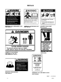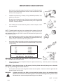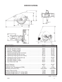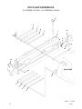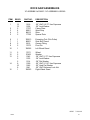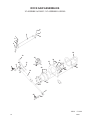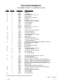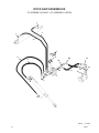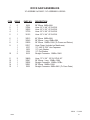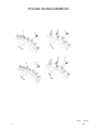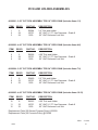
1
OPERATOR’S AND PARTS MANUAL RS18 & RS24 ROCK SAW SERIAL NUMBER: ___________________ MODEL NUMBER: ___________________ 800-456-7100 I www.paladinattachments.com Manual Number: OM689 Part Number: 75589 Rev. 6 503 Gay Street, Delhi, IA 52223, United States of America Copyright © 10493 1-2-15-8 TABLE OF CONTENTS PREFACE...........................................................................................................................................................3 SAFETY PRECAUTIONS SAFETY STATEMENTS............................................................................................................................ 5 GENERAL SAFETY PRECAUTIONS.....................................................................................................5-7 EQUIPMENT SAFETY PRECAUTIONS................................................................................................8-9 DECALS DECAL PLACEMENT.............................................................................................................................. 10 DECALS............................................................................................................................................. 11-12 INSTALLATION.........................................................................................................................................13-14 operating instructions rock saw operation..................................................................................................................15-17 storage...............................................................................................................................................17 transporting.................................................................................................................................... 17 LIFT POINTS........................................................................................................................................... 18 TIE DOWN POINTS................................................................................................................................ 18 maintenance AND SERVICE GENERAL INFORMATION...................................................................................................................... 19 ROUTINE MAINTENANCE..................................................................................................................... 19 PICK REPLACEMENT............................................................................................................................ 20 PICK AND HOLDER REPLACEMENT.................................................................................................... 21 HYDRAULIC MOTOR replacement OR REPAIR........................................................................21-22 PLANETARY REPLACEMENT OR REPAIR......................................................................................22-25 CHANGING PLANETARY OIL................................................................................................................ 25 cylinder seal replacement...................................................................................................26-27 troubleshooting.............................................................................................................................28-29 specifications bolt torque specifications........................................................................................................ 30 ROCK SAW specifications.............................................................................................................. 31 limited warranty.................................................................................................................................. 33 PARTS ROCK SAW ASSEMBLIES (MAINFRAME).......................................................................................34-35 ROCK SAW ASSEMBLIES (SIDE SHIFT FRAME)............................................................................36-37 ROCK SAW ASSEMBLIES (HYDRAULICS)......................................................................................38-39 ROCK SAW ASSEMBLIES (HYDRAULIC HOSES)...........................................................................40-41 PICK AND HOLDER ASSEMBLIES...................................................................................................42-43 POWER AND RETURN HYDRAULIC KITS ......................................................................................44-45 Planetary assembly - auburn................................................................................................46-47 OPTIONAL HOSE EXTENSION KIT..................................................................................................48-49 CYLINDER ASSEMBLY #106420......................................................................................................50-51 CYLINDER ASSEMBLY #105966......................................................................................................52-53 ELECTRICAL CONTROL HANDLE ASSEMBLY #104367...................................................................... 54 CONTROL BOX #104368 (USE WITH HARNESS #101096)................................................................. 55 ELECTRICAL WIRE HARNESS ASSEMBLY #101096........................................................................... 56 ELECTRICAL WIRE HARNESS ASSEMBLY #108035........................................................................... 57 ELECTRICAL WIRE HARNESS ASSEMBLY #108036........................................................................... 58 10565 75589 11-19-14-6 1 THIS PAGE IS INTENTIONALLY BLANK 2 75589 PREFACE GENERAL COMMENTS Congratulations on the purchase of your new BRADCO product! This product was carefully designed and manufactured to give you many years of dependable service. Only minor maintenance (such as cleaning and lubricating) is required to keep it in top working condition. Be sure to observe all maintenance procedures and safety precautions in this manual and on any safety decals located on the product and on any equipment on which the attachment is mounted. This manual has been designed to help you do a better, safer job. Read this manual carefully and become familiar with its contents. WARNING! Never let anyone operate this unit without reading the "Safety Precautions" and "Operating Instructions" sections of this manual. Always choose hard, level ground to park the vehicle on and set the brake so the unit cannot roll. Unless noted otherwise, right and left sides are determined from the operator’s control position when facing the attachment. NOTE: The illustrations and data used in this manual were current (according to the information available to us) at the time of printing, however, we reserve the right to redesign and change the attachment as may be necessary without notification. BEFORE OPERATION The primary responsibility for safety with this equipment falls to the operator. Make sure the equipment is operated only by trained individuals that have read and understand this manual. If there is any portion of this manual or function you do not understand, contact your local authorized dealer or the manufacturer to obtain further assistance. Keep this manual available for reference. Provide the manual to any new owners and/or operators. SAFETY ALERT SYMBOL This is the “Safety Alert Symbol” used by this industry. This symbol is used to warn of possible injury. Be sure to read all warnings carefully. They are included for your safety and for the safety of others working with you. SERVICE Use only manufacturer replacement parts. Substitute parts may not meet the required standards. Record the model and serial number of your unit on the cover of this manual. The parts department needs this information to insure that you receive the correct parts. SOUND AND VIBRATION Sound pressure levels and vibration data for this attachment are influenced by many different parameters: some items are listed below (not inclusive): • prime mover type, age, condition, with or without cab enclosure and configuration • operator training, behavior, stress level • job site organization, working material condition, environment Based on the uncertainty of the prime mover, operator, and job site, it is not possible to get precise machine and operator sound pressure levels or vibration levels for this attachment. NOTE: A list of all Paladin Patents can be found at http://www.paladinattachments.com/patents.asp. 10344 75589 7-31-13-4 3 THIS PAGE IS INTENTIONALLY BLANK 4 75589 SAFETY STATEMENTS THIS SYMBOL BY ITSELF OR WITH A WARNING WORD THROUGHOUT THIS MANUAL IS USED TO CALL YOUR ATTENTION TO INSTRUCTIONS INVOLVING YOUR PERSONAL SAFETY OR THE SAFETY OF OTHERS. FAILURE TO FOLLOW THESE INSTRUCTIONS CAN RESULT IN INJURY OR DEATH. DANGER THIS SIGNAL WORD IS USED WHERE SERIOUS INJURY OR DEATH WILL RESULT IF THE INSTRUCTIONS ARE NOT FOLLOWED PROPERLY. WARNING THIS SIGNAL WORD IS USED WHERE SERIOUS INJURY OR DEATH COULD RESULT IF THE INSTRUCTIONS ARE NOT FOLLOWED PROPERLY. CAUTION THIS SIGNAL WORD IS USED WHERE MINOR INJURY COULD RESULT IF THE INSTRUCTIONS ARE NOT FOLLOWED PROPERLY. NOTICE NOTICE INDICATES A PROPERTY DAMAGE MESSAGE. GENERAL SAFETY PRECAUTIONS WARNING! READ MANUAL PRIOR TO INSTALLATION Improper installation, operation, or maintenance of this equipment could result in serious injury or death. Operators and maintenance personnel should read this manual, as well as all manuals related to this equipment and the prime mover thoroughly before beginning installation, operation, or maintenance. FOLLOW ALL SAFETY INSTRUCTIONS IN THIS MANUAL AND THE PRIME MOVER’S MANUAL(S). READ AND UNDERSTAND ALL SAFETY STATEMENTS Read all safety decals and safety statements in all manuals prior to operating or working on this equipment. Know and obey all OSHA regulations, local laws, and other professional guidelines for your operation. Know and follow good work practices when assembling, maintaining, repairing, mounting, removing, or operating this equipment. KNOW YOUR EQUIPMENT Know your equipment’s capabilities, dimensions, and operations before operating. Visually inspect your equipment before you start, and never operate equipment that is not in proper working order with all safety devices intact. Check all hardware to ensure it is tight. Make certain that all locking pins, latches, and connection devices are properly installed and secured. Remove and replace any damaged, fatigued, or excessively worn parts. Make certain all safety decals are in place and are legible. Keep decals clean, and replace them if they become worn or hard to read. 10338 75589 8-16-05 5 GENERAL SAFETY PRECAUTIONS WARNING! PROTECT AGAINST FLYING DEBRIS Always wear proper safety glasses, goggles, or a face shield when driving pins in or out, or when any operation causes dust, flying debris, or any other hazardous material. WARNING! LOWER OR SUPPORT RAISED EQUIPMENT Do not work under raised booms without supporting them. Do not use support material made of concrete blocks, logs, buckets, barrels, or any other material that could suddenly collapse or shift positions. Make sure support material is solid, not decayed, warped, twisted, or tapered. Lower booms to ground level or on blocks. Lower booms and attachments to the ground before leaving the cab or operator’s station. WARNING! USE CARE WITH HYDRAULIC FLUID PRESSURE Hydraulic fluid under pressure can penetrate the skin and cause serious injury or death. Hydraulic leaks under pressure may not be visible. Before connecting or disconnecting hydraulic hoses, read your prime mover’s operator’s manual for detailed instructions on connecting and disconnecting hydraulic hoses or fittings. • Keep unprotected body parts, such as face, eyes, and arms as far away as possible from a suspected leak. Flesh injected with hydraulic fluid may develop gangrene or other permanent disabilities. • If injured by injected fluid, see a doctor at once. If your doctor is not familiar with this type of injury, ask him to research it immediately to determine proper treatment. • Wear safety glasses, protective clothing, and use a piece of cardboard or wood when searching for hydraulic leaks. DO NOT USE YOUR HANDS! SEE ILLUSTRATION. CARDBOARD HYDRAULIC HOSE OR FITTING MAGNIFYING GLASS 10339 6 8-16-05 75589 GENERAL SAFETY PRECAUTIONS WARNING! DO NOT MODIFY MACHINE OR ATTACHMENTS Modifications may weaken the integrity of the attachment and may impair the function, safety, life, and performance of the attachment. When making repairs, use only the manufacturer’s genuine parts, following authorized instructions. Other parts may be substandard in fit and quality. Never modify any ROPS (Roll Over Protection Structure) or FOPS (Falling Object Protective Structure) equipment or device. Any modifications must be authorized in writing by the manufacturer. WARNING! SAFELY MAINTAIN AND REPAIR EQUIPMENT • Do not wear loose clothing or any accessories that can catch in moving parts. If you have long hair, cover or secure it so that it does not become entangled in the equipment. • Work on a level surface in a well-lit area. • Use properly grounded electrical outlets and tools. • Use the correct tools for the job at hand. Make sure they are in good condition for the task required. • Wear the protective equipment specified by the tool manufacturer. SAFELY OPERATE EQUIPMENT Do not operate equipment until you are completely trained by a qualified operator in how to use the controls, know its capabilities, dimensions, and all safety requirements. See your machine’s manual for these instructions. • Keep all step plates, grab bars, pedals, and controls free of dirt, grease, debris, and oil. • Never allow anyone to be around the equipment when it is operating. • Do not allow riders on the attachment or the prime mover. • Do not operate the equipment from anywhere other than the correct operator’s position. • Never leave equipment unattended with the engine running, or with this attachment in a raised position. • Do not alter or remove any safety feature from the prime mover or this attachment. • Know your work site safety rules as well as traffic rules and flow. When in doubt on any safety issue, contact your supervisor or safety coordinator for an explanation. 10340 75589 8-16-05 7 EQUIPMENT SAFETY PRECAUTIONS WARNING! KNOW WHERE UTILITIES ARE Observe overhead electrical and other utility lines. Be sure equipment will clear them. When digging, call your local utilities for location of buried utility lines, gas, water, and sewer, as well as any other hazard you may encounter. WARNING! EXPOSURE TO RESPIRABLE CRYSTALLINE SILICA DUST ALONG WITH OTHER HAZARDOUS DUSTS MAY CAUSE SERIOUS OR FATAL RESPIRATORY DISEASE. This attachment is designed to cut rock, concrete and asphalt, causing high levels of dust. It is recommended to use dust suppression, dust collection and if necessary personal protective equipment during the operation of the rock saw or of any attachment that may cause high levels of dust. WARNING! REMOVE PAINT BEFORE WELDING OR HEATING Hazardous fumes/dust can be generated when paint is heated by welding, soldering or using a torch. Do all work outside or in a well ventilated area and dispose of paint and solvent properly. Remove paint before welding or heating. When sanding or grinding paint, avoid breathing the dust. Wear an approved respirator. If you use solvent or paint stripper, remove stripper with soap and water before welding. Remove solvent or paint stripper containers and other flammable material from area. Allow fumes to disperse at least 15 minutes before welding or heating. WARNING! END OF LIFE DISPOSAL At the completion of the useful life of the unit, drain all fluids and dismantle by separating the different materials (rubber, steel, plastic, etc.). Follow all federal, state and local regulations for recycling and disposal of the fluid and components. OPERATING THE ROCK SAW • • • • • • • • Block off work area from bystanders, livestock, etc. Operate only from the operator’s station. When operating on slopes, drive up and down, not across. Avoid steep hillside operation, which could cause the prime mover to overturn. Reduce speed when driving over rough terrain, on a slope, or turning, to avoid overturning the vehicle. An operator must not use drugs or alcohol, which can change his or her alertness or coordination. An operator taking prescription or over-the-counter drugs should seek medical advice on whether or not he or she can safely operate equipment. Before exiting the prime mover, lower the attachment to the ground, turn off the prime mover’s engine, remove the key and apply the brakes. Be sure all doors, guards and shields are in their proper position and securely attached before operating the Rock Saw. Do not attempt to move the saw sideways while it is in the ground. 10494 8 7-24-14-3 75589 EQUIPMENT SAFETY PRECAUTIONS TRANSPORTING THE ROCK SAW • • • • Travel only with the attachment in a safe transport position to prevent uncontrolled movement. Drive slowly over rough ground and on slopes. When driving on public roads use safety lights, reflectors, Slow Moving Vehicle signs etc., to prevent accidents. Check local government regulations that may affect you. Do not drive close to ditches, excavations, etc., cave in could result. Do not smoke when refueling the prime mover. Allow room in the fuel tank for expansion. Wipe up any spilled fuel. Secure cap tightly when done. MAINTAINING THE ROCK SAW • • • • • Before performing maintenance, lower the attachment to the ground, turn off the engine, remove the key and apply the brakes. Never perform any work on the attachment unless you are authorized and qualified to do so. Always read the operator service manual’s before any repair is made. After completing maintenance or repair, check for correct functioning of the attachment. If not functioning properly, always tag “DO NOT OPERATE” until all problems are corrected. Worn, damaged, or illegible safety decals must be replaced. New safety decals can be ordered from BRADCO. Never make hydraulic repairs while the system is under pressure. Serious personal injury or death could result. Never work under a raised attachment. 11491 9-30-09 75589 9 DECALS DECAL PLACEMENT GENERAL INFORMATION The diagrams on this page show the location of the decals used on the Rock Saws. The decals are identified by their part numbers, with reductions of the actual decals located on the following pages. Use this information to order replacements for lost or damaged decals. Be sure to read all decals before operating the attachment. They contain information you need to know for both safety and longevity. Logo #40149 #40922 #40151 #40855 #40719 CONTROL DECAL * (SEE NOTE BELOW) #40916 #40920 #41043 #40922 #4468 #40440 serial tag location #40678 #4468 #40150 #40922 Logo #40149 #40923 #40855 #40719 #4468 * NOTE: ATTACHMENT CONTROL DECALS ARE PURCHASED ACCORDING TO THE MULTI-FUNCTION ELECTRIC CONTROL HANDLE YOUR UNIT IS EQUIPPED WITH. NOT REQUIRED WHEN USED WITH BRADCO CONTROL BOX. IMPORTANT: Keep all safety decals clean and legible. Replace all missing, illegible, or damaged safety decals. When replacing parts with safety decals attached, the safety decals must also be replaced. REPLACING SAFETY DECALS: Clean the area of application with nonflammable solvent, then wash the same area with soap and water. Allow the surface to fully dry. Remove the backing from the safety decal, exposing the adhesive surface. Apply the safety decal to the position shown in the diagram above and smooth out any bubbles. 10495 11-19-14-3 10 75589 DECALS WARNING! BEFORE LEAVING SEAT PART #40678 DEPTH CONTROL PART #40920 (18” ROCK SAW) PART #40916 (24” ROCK SAW) LOCKING PIN OPERATION PART #40923 note: contact your local dealer to purchase logo and model number decals LIFT HOOK PART #40922 *ATTACHMENT CONTROLS CASE STYLE PART #40934 *ATTACHMENT CONTROLS NEW HOLLAND & CASE STYLE PART #40933 *NOTE: ATTACHMENT CONTROL DECALS ARE PURCHASED ACCORDING TO THE MULTI-FUNCTION ELECTRIC CONTROL HANDLE YOUR UNIT IS EQUIPPED WITH. none required with the bradco control box. 10496 75589 11-19-14-2 11 DECALS WARNING! HIGH PRESSURE FLUID PART #40151 DANGER! FLYING DEBRIS PART #40719 (7.38” X 5”) PART #40855 (6” X 4.18”) WARNING! READ MANUAL PART #40150 WARNING! HAZARDOUS DUST PART #41043 DANGER! PINCH POINT PART #40149 WARNING! FOOT CRUSH PART #4468 warning! CALL BEFORE YOU DIG PART #40440 10497 12 11-19-14-3 75589 INSTALLATION GENERAL INFORMATION The following instructions will help you to mount your rock saw onto your skid steer loader. The rock saw uses the quick-attach system for ease of installation. Therefore, if you know how to attach your loader bucket, attaching the rock saw should prove no problem. Remember to read all safety warnings, decals and operating instructions before operating the attachment. If there is any portion of this manual that you do not understand, contact your dealer. WARNING! THE 18” AND 24” ROCK SAWS ARE DESIGNED FOR USE ON HIGH FLOW HYDRAULIC SYSTEMS. DO NOT ATTACH OR OPERATE ANY ATTACHMENT THAT EXCEEDS THE RECOMMENDED LIFTING CAPACITY OF YOUR SKID STEER. WARNING! EXPOSURE TO RESPIRABLE CRYSTALLINE SILICA DUST ALONG WITH OTHER HAZARDOUS DUSTS MAY CAUSE SERIOUS OR FATAL RESPIRATORY DISEASE. This attachment is designed to cut rock, concrete and asphalt, causing high levels of dust. It is recommended to use dust suppression, dust collection and if necessary personal protective equipment during the operation of the rock saw or of any attachment that may cause high levels of dust. IMPORTANT Concrete and masonry products contain silica sand. Quartz, which is a form of silica and the most common mineral in the earths crust, is associated with many types of rock. Some activities that silica dust may be present in the air include demolition, sweeping, loading, sawing, hammering, drilling or planing of rock, concrete or masonry. It is recommended to use dust suppression (such as water), dust collection (such as a vacuum) along with personal protective equipment if necessary during the operation of any attachment that may cause high levels of silica dust. INSTALLATION INSTRUCTIONS 1. Remove the shipping banding from around the rock saw and skid. 2. Remove any attachments from the front of the loader. 3. Following all standard safety practices and the instructions for installing an attachment in your skid steer operator's manual, install the rock saw onto your skid steer. NOTE: It is important to make sure the locking mechanism on your quick attach is engaged, therefore locking the attachment onto the skid steer. 4. Lower the unit to the ground and remove the key. 10544 75589 9-30-09-2 13 INSTALLATION 5. Relieve any pressure from the auxiliary hydraulic system and after making sure that there is not any foreign matter on the hydraulic couplers, connect the case drain coupler to the case drain on your skid steer loader. 6. Connect the power and return couplers to the high flow auxiliary hydraulic system of your skid steer loader. Hose tie the hoses together and route the hoses in such a fashion as to avoid pinching or chafing. CAUTION! BE SURE CASE DRAIN COUPLER IS COMPLETELY ENGAGED. IMMEDIATE HYDRAULIC MOTOR SEAL FAILURE AND PLANETARY DAMAGE WILL OCCUR IF CASE DRAIN IS NOT SUCCESSFULLY CONNECTED. 7. Connect the electrical wire harness from the rock saw to the auxiliary electrical connector on the front of the skid steer (if so equipped). If your skid steer is not equipped with an electrical connector and you are using the BRADCO control handle, connect the wiring harness to the control handle and place the control handle inside of the skid steer operator's station. WARNING! Do not operate the rock saw from outside of the skid steer operator's station. 8. Following all standard safety practices, start the skid steer and run all cylinders through their full cycle to purge any air from the system. Check that all controls function in accordance with BRADCO control box or with the operating decal (if so equipped). Your rock saw is now installed and ready for operation. DISCONNECT INSTRUCTIONS 1. Center the rock saw on the side shift frame. 2. Adjust depth setting to "PARK" and engage the locking pin on the right side of the rock saw. 3. Set attachment on a firm level surface. 4. Following Safety Shut Down Procedures; stop the engine and set the parking brake. Relieve any pressure in the hydraulic lines. 5. Disconnect the power and return hoses from the auxiliary hydraulics and then disconnect the case drain hose. 6. Disconnect the electrical wire harness from the auxiliary electrical connector or the BRADCO control handle. 7. Following all standard safety practices and the instructions for disconnecting an attachment in your skid steer operator's manual, disconnect the rock saw from your skid steer allowing the attachment to lower onto the stands as the skid steer is disengaged. 8. Connect the hydraulic couplers on the attachment together to prevent contaminants from entering the hydraulic system. 10545 14 9-30-09-2 75589 OPERATING INSTRUCTIONS INTENDED USE: This unit is designed to cut through horizontal surfaces consisting of rock, concrete and asphalt. Use in any other way is considered contrary to the intended use. GENERAL INFORMATION The rock saw attaches to the toolbar/quick-attach mechanism of your skid steer loader. Due to this arrangement, thorough knowledge of the skid steer controls is necessary for machine operation. Read and understand your skid steer operator's manual for information regarding skid steer operation before attempting to use the attachment. Check the operating surface. The standard all purpose picks can be used to saw both asphalt and concrete. There are optional concrete picks that are recommended if the rock saw is to be used extensively for concrete. These picks do not perform as well when sawing through asphalt, especially in warmer weather. Review the job at hand and determine the required depth and the side shift position of the rock saw. Best performance is obtained when the rock saw is in the center position. Side shift should be used when visibility is a determining factor such as sawing next to an obstacle such as a building. NOTICE: The wheel/planetary nuts (#10003) must be torqued to 220-260 ft. lbs after the first four hours of operation and every 40 hours thereafter. ROCK SAW OPERATION WARNING! CHECK THE WORK AREA AND KNOW WHERE ALL UTILITY LINES ARE BEFORE OPERATING THE ROCK SAW. OPERATE THE ROCK SAW FROM INSIDE THE OPERATOR’S STATION OF YOUR SKID STEER LOADER ONLY. 1. Clear area of all bystanders. NOTE: There is a control valve on the rock saw that can be manually set to change the speed of the lift cylinder. Before operation, place the locking pin in the operation position and run the lift cylinder through a complete cycle noting the speed. For maximum production it is recommended that the harder the material the slower the cylinder speed. 2. Determine the desired depth and shift the cutting wheel to the required side shift location. Position the rock saw at the starting point of the cut. Place the locking pin in the operation position. 3. With the skid shoe in the PARK position, place the skid shoe on the ground and roll out the loader bucket cylinder until the front tires of the skid steer are off the ground 4. With the cutting wheel off the ground, start wheel rotation. (Picks at the bottom of the wheel must be moving in the same forward direction that the rock saw travels. If they are not, change the power and return hoses at the motor end.) 10546 75589 11-19-14-2 15 OPERATING INSTRUCTIONS 5. Increase engine to full RPM. Start the sawing operation by retracting the skid shoe with the lift cylinder. This must be done slowly to avoid stalling the machine. If the rock saw stalls you are retracting the skid shoe faster than the saw is cutting. Lower the skid shoe (which will lift the cutting wheel) until the wheel restarts. 6. Retract the skid shoe until the desired depth is achieved. If the rock saw continues to stall, shut down and reset the control valve to slow down cylinder speed. NOTE: When the skid shoe begins to come off the ground and the front tires of the skid steer have reached the ground, stop retracting the lift cylinder and roll the loader bucket cylinder out to get the front tires back off the ground. 7. Advance forward. If the rock saw stalls, you are traveling faster than the saw is cutting. Back out of the cut until the wheel restarts and then advance slowly. NOTE: Do NOT side shift the rock saw while the wheel is in the cut. The cutting wheel will not cut in a side to side direction. OPERATING TIPS • For optimal cutting and reduced vibration, operate the rock saw with the rear tires of the loader and the rock saw rollers on the ground and enough down pressure on the skid shoe to prevent the saw from plunging into the ground and stalling. NOTE: This is not possible with some skid steer applications. • If the rock saw is stalling out you are either traveling too fast or retracting the skid shoe faster then the saw is cutting. Back out of the cut or lower the skid shoe until the wheel restarts. • When the skid shoe begins to come off the ground and the front tires of the skid steer have reached the ground, stop retracting the lift cylinder and roll the loader bucket cylinder out to lift the front tires back off the ground. ENDING THE CUT 1. To end the cutting operation, stop all forward movement and raise the cutting wheel out of the cut by lowering the skid shoe to the PARK position. 2. Idle the loader engine and turn the rock saw off. DO NOT TRANSPORT THE ROCK SAW WHILE THE CUTTING WHEEL IS IN MOTION. 3. Move the unit away from the cut. 4. Lower the attachment to the ground and turn off the loader engine. 5. Apply the brakes and remove the key before leaving the operator’s station. 6. Install the locking pin in the PARK/TRANSPORT position. 10547 16 3-16-06 75589 OPERATING INSTRUCTIONS NOTICE: Periodic observation must be made of the transmission oil temperature indicator when sawing with the high flow hydraulic systems. Depending on the ambient temperature and the duty cycle of the machine hydraulic oil may overheat. If indicator comes on, shut off the rock saw and allow the skid steer to idle until the temperature falls below 160° Fahrenheit. If the system continues running hot it may be necessary to clean any debris from the oil cooler and radiator. Check engine air filter and also the hydraulic oil level. Continuous or excessive overheating may cause machine damage. STORAGE 1. 2. 3. 4. 5. 6. 7. 8. 9. Clean the unit thoroughly removing all mud, dirt and grease. Inspect for visible signs of wear, breakage, or damage.. Order any parts required and make necessary repairs to avoid delays upon removal from storage.. Check for missing or worn picks. Replace as required. Tighten loose nuts, capscrews and hydraulic connections. Coat all exposed cylinder rods with grease. Grease all grease fittings. Seal hydraulic system from contaminants and secure all hydraulic hoses off the ground to help prevent damage. Replace decals if damaged or in unreadable condition. Store unit in a dry and protected place. Leaving the unit outside will materially shorten its life. Additional Precautions for Long Term Storage: 1. Touch up all unpainted surfaces with paint to prevent rust. REMOVAL FROM STORAGE 1. 2. 3. 4. Remove all protective coverings. Wash unit and replace any damaged and/or missing parts. Lubricate grease fittings. Check hydraulic hoses for deterioration and replace if necessary. TRANSPORTING 1. 2. 3. Check that the Locking Pin is in the Transport (LOCK) position. Use extra care when loading and unloading the machine onto a truck or trailer. Follow all federal, state and local regulations that may apply along with recommended tiedown points and any equipment safety precautions at the front of this manual when transporting your attachment. 10548 75589 11-19-14-2 17 OPERATING INSTRUCTIONS LIFT POINTS Lifting points are identified by lifting decals where required. Lifting at other points is unsafe and can damage attachment. Do not attach lifting accessories around cylinders or in any way that may damage hoses or hydraulic components. • Attach lifting accessories to unit at recommended lifting points. • Bring lifting accessories together to a central lifting point. • Lift gradually, maintaining the equilibrium of the unit. WARNING! Use lifting accessories (chains, slings, ropes, shackles and etc.) that are capable of supporting the size and weight of your attachment. Secure all lifting accessories in such a way to prevent unintended disengagement. Failure to do so could result in the attachment falling and causing serious personal injury or death. TIE DOWN POINTS Tie down points are identified by tie down decals where required. Securing to trailer at other points is unsafe and can damage attachment. Do not attach tie down accessories around cylinders or in any way that may damage hoses or hydraulic components. • Attach tie down accessories to unit as recommended. • Check unit stability before transporting. WARNING! Verify that all tie down accessories (chains, slings, ropes, shackles and etc.) are capable of maintaining attachment stability during transporting and are attached in such a way to prevent unintended disengagement or shifting of the unit. Failure to do so could result in serious personal injury or death. 12927 18 11-19-14 75589 MAINTENANCE AND SERVICE GENERAL INFORMATION Regular maintenance is the key to long equipment life and safe operation. Maintenance requirements have been reduced to an absolute minimum. However it is very important that these maintenance functions be performed as described below. WARNING! Never do any maintenance to this attachment while it is running. Exercise the MANDATORY SAFETY SHUTDOWN PROCEDURE BEFORE working on or around the attachment. • AFTER FIRST 4 HOURS (BREAK IN PERIOD) Torque the wheel/planetary nuts (#10003) to 220-260 ft. lbs. (298-353 N.m). Procedure Daily Case Drain Coupler - Check for complete engagement of coupler. Hydraulic Oil - Check prime mover hydraulic system for adequate oil levels. Hardware - Check for tightness (see Bolt Torque Specifications) Hydraulic System - Check for leaks and tighten as necessary. Check for damage and replace as needed. Decals - Check for missing or damaged safety decals and replace as necessary. Picks - Check for freedom of rotation, flat spots and wear. Replace worn or missing picks or any picks that are not rotating freely or have flat spots. Inspect attachment for any worn parts or cracked welds. Repair as required. Lubricate grease fittings on the lift arm pin and the pivot pins on the left and right stand. Lubricate grease fittings on cylinder ends. Torque the wheel/planetary nuts (#10003) to 220-260 ft. lbs. (298353 N.m). Change gear oil (Castrol SP320) in planetary. (After first 50 Hour Break In Period) See Maintenance and Service Every 40 Hours 1000 Hours or 12 Months 2500 Hours or 12 Months Auburn Planetary Digga Planetary WARNING! Escaping fluid under pressure can have sufficient force to penetrate the skin causing serious personal injury. Fluid escaping from a very small hole can be almost invisible. Use a piece of cardboard or wood, rather than hands to search for suspected leaks. Keep unprotected body parts, such as face, eyes, and arms as far away as possible from a suspected leak. Flesh injected with hydraulic fluid may develop gangrene or other permanent disabilities. If injured by injected fluid, see a doctor at once. If your doctor is not familiar with this type of injury, ask him to research it immediately to determine proper treatment. 10549 11-19-14-3 75589 19 MAINTENANCE AND SERVICE IMPORTANT: When replacing parts use only factory approved replacement parts. Manufacturer will not claim responsibility for use of unapproved parts or accessories and/or other damages as a result of their use. PICK REPLACEMENT Picks should be replaced if you are changing to a different application pick, they are broken, worn, flat spot or are seized in the pick holder and do not rotate freely. WARNING! Always wear safety glasses with side shields when striking metal. Failure to heed could result in serious injury to the eyes or other parts of the body. DO NOT attempt to check the picks with the rock saw in a raised and unsupported position. 1. Raise the skid shoe / lift arm by retracting the lift cylinder and installing the locking pin to prevent the lift arm from accidentally lowering. 2. Support the rock saw by attaching a lift hook on the left side of the mainframe in the “D” ring provided. 3. Hold the extracting tool (pick puller) in one hand and place the jaws in the groove of the pick, with the offset handle pointing away from the pick holder. 4. Using a lead hammer or rubber-headed mallet, hit the raised pad on the tool until the pick starts to move. Continue tapping until the pick is removed. 5. Insert the new pick into the jaws of the extracting tool (pick puller) so that the raised pad of the tool is pointing in the same direction as the pick point. 6. Position the new pick in the pick holder on the drum and with a lead hammer or rubberheaded mallet, hit the raised pad of the tool to start the pick into the pick holder. (Clean out any foreign material from the pick holder before installing the new pick.) 7. Once the pick is started into the pick holder strike the tool pad one strong blow to pop the pick into the holder. PICK REMOVAL PICK EXTRACTING TOOL PICK HOLDER PICK INSTALLATION PICK EXTRACTING TOOL PICK HOLDER NOTE: The pick is properly seated when its shoulder is against the face of the pick holder. Check to be sure the pick rotates freely. 10550 20 5-11-06 75589 MAINTENANCE AND SERVICE 8. When all accessible picks have been changed, clear the area of bystanders and start the loader. Slowly rotate the cutting wheel approximately 1/4 turn to access more picks. 9. Repeat Steps #3 through #8 until all picks have been replaced. PICK AND HOLDER REPLACEMENT. It will be necessary to change the complete bolt-on pick holder if the holder is damaged or when changing the width of cut. 1. Raise the skid shoe / lift arm by retracting the lift cylinder and installing the locking pin to prevent the lift arm from accidentally lowering. 2. Support the rock saw by attaching a lift hook on the left side of the mainframe in the “D” ring provided. 3. Replace the desired pick holders with new hardware. Torque to specification. (See Bolt Torque Specification Section.) NOTE: You must have all 2.5” cut holders or all 4.00” cut holders to main.62” unc x 1.75” capscrew tain the balance on the cutting wheel. (grade 8) Different size holders will cause the rock saw to vibrate and bounce and greatly reduce the performance. The pick holders must all be mounted on countersunk the same side of the cutting wheel as side of cutting the planetary with the mounting bolts wheel going into the countersunk hole on the wheel and the lock nuts on the outside cutting wheel of the holder. .62” unc deformed lock nut pick holder HYDRAULIC MOTOR REPLACEMENT OR REPAIR IMPORTANT: Replacing INTERNAL motor seals or disassembly of the motor will void warranty. NOTICE: Damage to the motor shaft seal may be caused by excessive case drain pressure due to unconnected or malfunctioning drain line. 1. Tag and disconnect the power and return hoses along with the case drain hose from the hydraulic motor. Cap or plug hose ends and motor ports to prevent contaminants from entering the hydraulic system. 2. Remove the capscrews securing the motor to the planetary. 10551 75589 5-11-06 21 MAINTENANCE AND SERVICE 3. Clean all mating surfaces of the planetary to prepare it for the new motor. NOTE: If not bolting new motor on immediately, cover planetary to prevent contaminants from entering the hydraulic system. NOTE: If replacing shaft seals: Replace seals and gasket and continue with Step #4 to reinstall existing motor. 4. Replace the motor gasket #102594 between the motor and the planetary. 5. Bolt the new or repaired motor onto the planetary using the existing hardware. (Check to make sure the motor is in the correct position with the ports turned up.) Torque to specification. (See Bolt Torque Specification Section.) 6. Reconnect the hydraulic hoses and fittings to the motor. 9. Refill planetary with Gear Oil (Castrol SP 320) through the fill plug located on the top of the planetary. 10. Check for leaks and tighten as required. PLANETARY REPLACEMENT or repair A hoist with at least a 3000 lb. capacity is required when removing the planetary or shaft seal. NOTE: Leaking planetary shaft seal can be caused by a damaged motor seal leaking oil into the planetary. Check motor seal first if planetary is leaking. If motor seal is damaged go to “HYDRAULIC MOTOR REPLACEMENT OR REPAIR” and change motor seal. IMPORTANT: Replacing internal motor seals or disassembly of the planetary will void warranty. 1. Disconnect the rock saw from the skid steer loader by following the “Disconnect Instructions” in the Installation section of this manual. 2. Attach the hoist to both lift hook locations on the left side of the rock saw (mainframe and side shift frame). 3. Slowly and very carefully lift the rock saw and remove the rod end lift cylinder pin and locking pin. Lay the rock saw on its side with the planetary up and manually position the lift arm and skid shoe in the up position. (Blocking up the front of the attachment to keep it fairly level is recommended but not required.) 4. Tag and disconnect the power and return hoses along with the case drain hose from the hydraulic motor. Cap or plug hose ends and motor ports to prevent contaminants from entering the hydraulic system. 5. Remove the motor guard. 10552 22 5-11-06 75589 MAINTENANCE AND SERVICE TAG AND REMOVE HOSES FROM MOTOR REMOVE MOTOR GUARD DISCONNECT LIFT CYLINDER AND MANUALLY ROTATE LIFT ARM UP blOCK UP FRONT OF ROCK SAW NOTE: The planetary and wheel assembly will need to be supported for removal. It is recommended that you have two .62” UNC eyebolts for this purpose. 6. Remove two of the .62” X 2.50” bolts securing the planetary to the planetary mounting plate and install two .62” UNC eyebolts. Attach hoist to eyebolts to support wheel assembly for removal. CAUTION! Be sure the wheel and planetary assembly is securely supported before removal of the bolts in step #7. Failure to properly support the assembly will allow the wheel to drop and may cause machine damage or injury. INSTALL .62” UNC EYEBOLTS INTO PLANETARY AND MOUNTING PLATE .75” UNC X 1.75” BOLTS (LIFT ARM REMOVED FOR CLARITY) ATTACH HOIST TO EYEBOLTS TO SUPPORT WHEEL ASSEMBLY SLIDE WHEEL ASSEMBLY OUT OF MAINFRAME 7. Remove the four .75” UNC X 1.75” bolts securing the planetary mounting plate to the mainframe. (This will free the wheel assembly from the mainframe. Be sure the assembly is sufficiently supported.) 8. Using the hoist to support the wheel and planetary assembly, slide it out of the mainframe. 10553 75589 5-11-06 23 MAINTENANCE AND SERVICE 9. Support the cutting wheel securely off the ground and remove the eight .62” lock nuts securing the planetary to the cutting wheel. NOTE: Make sure the cutting wheel is properly supported.When the lock nuts are removed the cutting wheel is no longer supported with the eyebolts. 10. Install the new planetary to the cutting wheel using the existing hardware. 11. Remove the eyebolts and the remaining .62” bolts securing the planetary to the mounting plate. Remove the mounting plate. INSTALL EYEBOLTS TO SUPPORT WHEEL ASSEMBLY FOR INSTALLATION INTO MAINFRAME INSTALL MOTOR INSTALL PLANETARY MOUNTING PLATE INSTALL NEW PLANETARY ONTO WHEEL 12. Install the mounting plate onto the new planetary using the existing hardware and the two eyebolts for installing into the mainframe. 13. Remove the capscrews securing the motor to the old planetary. 14. Clean the mating surface of the motor to prepare it for the installation onto the new planetary. NOTE: If replacing shaft seals: Replace seals and continue with Step #12 to reinstall existing components. NOTE: Leaking planetary shaft seal can be caused by a damaged motor seal leaking oil into the planetary. Check motor seal first if planetary is leaking. 15. Install a new motor gasket #102594 between the motor and the new planetary. Bolt the motor onto the new planetary using the existing hardware. (Check to make sure the motor is in the correct position with the ports turned up.) Torque to specification. NOTE: It is recommended that all picks be inspected and replaced if necessary and that the pick holder hardware be checked and tightened while the wheel is removed. 16. Connect the hoist to the eyebolts and reinstall the wheel and planetary assembly into the mainframe. Secure to the mainframe by installing the existing .75” hardware. Be sure to use the three 2.00” long bolts for reinstalling the motor guard. 10554 24 5-11-06 75589 MAINTENANCE AND SERVICE 17. Remove the eyebolts and install the last two .62” bolts. 18. Reconnect the hydraulic hoses and fittings to the motor. 19. Clear the area of any bystanders and slowly lift the rock saw (using the hoist) to an upright position. Position the lift cylinder and install the rod end cylinder pin and locking pin in the “Park” position. 20. Remove lift hooks and attach rock saw to your skid steer by following the “Installation Instructions” in the installation section of this manual. 21. Check for leaks and tighten as required. CHANGING PLANETARY OIL NOTICE: Disassembly of the planetary will void warranty. The planetary is a sealed unit. If there is any sign of oil leaks please contact your nearest BRADCO dealer before carrying out any repairs. There can be other causes for seal leaks. The planetary uses the Gear Oil (Castrol SP 320 for lubrication of gears and bearings. The Digga planetary uses approximately 2 quarts (1.9 liters) of gear oil while the Auburn planetary uses approximately 1 quart (.9 liters) of gear oil. The Digga planetary gear oil should be drained and replaced after the first 50 hours of use and every 12 months or 2500 hours - which ever comes first. The Auburn planetary gear oil should be drained and replaced after the first 50 hours of use. Thereafter every 12 months or 1000 hours - whichever comes first. PLANETARY IDENTIFICATION OIL PLUG DIGGA (SHOWN) AUBURN 10555 75589 11-19-14-2 25 MAINTENANCE AND SERVICE CYLINDER SEAL REPLACEMENT The following information is provided to assist you in the event you should need to repair or rebuild a hydraulic cylinder. When working on hydraulic cylinders, make sure that the work area and tools are clean and free of dirt to prevent contamination of the hydraulic system and damage to the hydraulic cylinders. Always protect the active part of the cylinder rod (the chrome section). Nicks or scratches on the surface of the rod could result in cylinder failure. Clean all parts thoroughly with a cleaning solvent before reassembly. DISASSEMBLY PROCEDURE IMPORTANT: Do not contact the active surface of the cylinder rod with the vise. Damage to the rod could result. THREADED TYPE GLAND Rotate the gland with a spanner wrench counterclockwise until the gland is free of the cylinder tube. Pull the cylinder rod from the cylinder tube and inspect the piston and the bore of the cylinder tube for deep scratches or galling. If damaged, the piston AND the cylinder tube must be replaced. 1. 2. 3. Remove the hex nut, piston, flat washer or spacer tube (if so equipped), and gland from the cylinder rod. If the cylinder rod is rusty, scratched, or bent, it must be replaced. Remove and discard all the old seals. 4. ASSEMBLY PROCEDURE IMPORTANT: Replace all seals even if they do not appear to be damaged. Failure to replace all seals may result in premature cylinder failure. NOTE: Seal kits will service most cylinders of similar bore size and rod diameter. 1. Install the cylinder rod seal in the gland first. Be careful not to damage the seal in the process, as it is somewhat difficult to install. NOTE: A special installation tool (Part #65349) is available to help with installing the seal. Simply fit the end of the tool over the seal so that the large prong of the tool is on the outside of the seal, and the two smaller prongs on the inside. The lip of the seal should be facing towards the tool. Rotate the handles on the tool around to wrap the seal around the end of the tool. 10356 26 10-13-05 75589 MAINTENANCE AND SERVICE Now insert the seal into the gland from the inner end. Position the seal in its groove, and release and remove the tool. Press the seal into its seat the rest of the way by hand. 2. Install the new piston ring, rod wiper, O-rings and backup washers, if applicable, on the piston. Be careful not to damage the seals. Caution must be used when installing the piston ring. The ring must be stretched carefully over the piston with a smooth, round, pointed tool. 3. After installing the rod seal inside the gland, as shown in step #1, install the external seal. NOTE: Threaded glands may have been equipped with a separate O-ring and backup washer system or a polypak (all in one) type seal. Current seal kits contain a polypak (all in one) type seal to replace the discarded seal types on ALL THREADED GLANDS. 4. Slide the gland onto the cylinder rod, being careful not to damage the rod wiper. Then install the spacer, or flat washer (if so equipped), small o-ring, piston, and hex nut onto the end of the cylinder rod. 5. Secure the cylinder rod (mounting end) in a vise with a support at its center. Torque the nut to the amount shown for the thread diameter of the cylinder rod (see chart). Thread Diameter 7/8" *1" 1-1/8" 1-1/4" 1-3/8" POUNDS - FEET 150-200 230-325 350-480 490-670 670-900 * 1" Thread Diameter WITH 1.25" Rod Diameter Min. 230 ft. lbs. Max. 250 ft. lbs. IMPORTANT: Do not contact the active surface of the cylinder rod with the vise. Damage to the rod could result. 6. Apply a lubricant (such as Lubriplate #105) to the piston and teflon ring. Insert the cylinder rod assembly into the cylinder tube. IMPORTANT: Ensure that the piston ring fits squarely into the cylinder tube and piston groove, otherwise the ring may be damaged and a leak will occur. 7. Use a spanner wrench to rotate the gland clockwise into the cylinder. Continue to rotate the gland with the spanner wrench until it is tight. WARNING! Cylinders serviced in the field are to be tested for leakage prior to the attachment being placed in work. Failure to test rebuilt cylinders could result in damage to the cylinder and/or the attachment, cause severe personal injury or even death. 10357 75589 10-13-05 27 TROUBLESHOOTING PROBLEM Motor on the rock saw will not operate. POSSIBLE CAUSE POSSIBLE SOLUTION Auxiliary hoses not hooked up to the skid-steer. Engage Couplers Obstruction in hydraulic lines. Remove obstruction and replace if necessary. Hydraulic motor damaged or seals blown. Call Bradco service department for instructions. Skid-steer auxiliary valve not engaged. Engage auxiliary valve. Rocks and debris caught between wheel and mainframe. Remove debris Insufficient hydraulic flow from the skid-steer. Refer to skid-steer's owners manual. Damaged quick coupler. Replace if necessary. Hydraulic motor damaged or seals blown. Call Bradco service department for instructions. Oil filter on skid-steer is dirty. Refer to skid-steer's owners manual. Loose or damaged hydraulic line. Tighten or replace. O-Rings on fittings damaged. Replace if necessary. Hydraulic motor damaged or seals blown. Call Bradco service department for instructions. Fittings loose or damaged. Tighten or replace. Cylinder seals damaged. Replace cylinder seals. Insufficient hydraulic flow from the skid-steer. Refer to skid-steer's owners manual. Relief valve setting adjusted too low. Refer to skid-steer's owners manual. Hydraulic motor damaged or seals blown. Call Bradco service department for instructions. Oil filter on skid-steer is dirty. Refer to skid-steer's owners manual. Wheel rotates in the wrong direction. Hoses from the valve to the motor incorrectly connected. Switch hoses at the motor end. Excessive vibration during operation. Picks are worn or broken. Inspect and replace as necessary. Picks contain flat spots or are not rotating freely. Inspect and replace as necessary. Two different size cutting pick holders. Verify wheel contains all 2.5” cutting width holders or 4.0” cutting width holders. Insufficient down force due to incorrect operating procedure. Refer to the Operating section of this manual. 10562 11-20-14-2 Wheel rotates sluggishly. Leaking Oil. Insufficient power. 28 75589 TROUBLESHOOTING PROBLEM Excessive oil temperature. A Hydraulic cylinder not operating. Hydraulic cylinders not functioning. Hydraulic cylinders only operating in one direction. POSSIBLE CAUSE POSSIBLE SOLUTION Hydraulic oil level too low. Refer to skid-steer's owners manual Obstruction in hydraulic lines. Remove obstruction and replace if necessary. Hydraulic oil or oil filter in skid-steer is dirty. Refer to skid-steer's owners manual. Relief valve setting adjusted too low. Refer to skid-steer's owners manual. Couplers not engaged. Engage couplers. Insufficient hydraulic flow from the skid-steer. Refer to skid-steer's owners manual. Cylinder rod bent. Visually inspect the cylinder for damage. Cylinder seals damaged. Replace cylinder seals. Obstruction in hydraulic lines. Remove obstruction and replace if necessary. Blown fuse on skid-steer. Refer to skid-steer's owners manual. Damaged electrical wiring. Test and replace if necessary. Faulty switch or electrical connection. Repair or replace as necessary. Solenoid valve spool bent. Replace spool. Faulty control valve coil. Replace coil. Contaminants in the hydraulic system and solenoid valve. Remove spool from solenoid valve and check for foreign material. Clean or replace. Remove spool from solenoid valve and check seals for damage. Replace if necessary. Damaged electrical wiring. Test and replace if necessary. Solenoid valve spool bent. Replace spool. Faulty control valve coil Replace coil. 10563 75589 11-20-14-2 29 BOLT TORQUE BOLT TORQUE SPECIFICATIONS GENERAL TORQUE SPECIFICATION TABLE Use the following torques when special torques are not given. These values apply to fasteners as received from suppliers, dry, or when lubricated with normal engine oil. They do not apply if special graphited or moly disulphide greases or other extreme pressure lubricants are used. This applies to both UNF and UNC threads. Remember to always use grade five or better when replacing bolts. IMPORTANT: On all PLATED GRADE 8 bolts, reduce torque 15% from listed bolt torque specification. SAE Grade No. Bolt head identification marks as per grade. NOTE: Manufacturing Marks Will Vary 2 5 TORQUE Bolt Size Inches Millimeters Pounds Feet Min. Max. 8* TORQUE Newton-Meters Min. Max. Pounds Feet Min. Max. TORQUE Newton-Meters Min. Max. Pounds Feet Min. Max. Newton-Meters Min. Max. 1/4 6.35 5 6 7 8 9 11 12 15 12 15 16 20 5/16 7.94 10 12 14 16 17 20.5 23 28 24 29 33 39 3/8 9.53 20 23 27 31 35 42 48 57 45 54 61 73 7/16 11.11 30 35 41 47 54 64 73 87 70 84 95 114 1/2 12.70 45 52 61 70 80 96 109 130 110 132 149 179 9/16 14.29 65 75 88 102 110 132 149 179 160 192 217 260 5/8 15.88 95 105 129 142 150 180 203 244 220 264 298 358 3/4 19.05 150 185 203 251 270 324 366 439 380 456 515 618 7/8 22.23 160 200 217 271 400 480 542 651 600 720 814 976 1 25.40 250 300 339 406 580 696 787 944 900 1080 1220 1464 1-1/8 25.58 - - - - 800 880 1085 1193 1280 1440 1736 1953 1-1/4 31.75 - - - - 1120 1240 1519 1681 1820 2000 2468 2712 1-3/8 34.93 - - - - 1460 1680 1980 2278 2380 2720 3227 3688 1-1/2 38.10 - - - - 1940 2200 2631 2983 3160 3560 4285 4827 * Thick Nuts must be used with Grade 8 bolts METRIC BOLT TORQUE SPECIFICATIONS Coarse Thread Size of Screw Grade No. Ptich (mm) Newton-Meters 3.6-5.8 4.9-7.9 5.8-.4 7.9-12.7 10.9 7.2-10 9.8-13.6 - - 5.6 7.2-14 9.8-19 12-17 16.3-23 19-27 25.7-36.6 5.6 M6 M8 M10 M12 M14 M16 8.8 8.8 1.0 - - - 23-29.8 27.1-35.2 22-31 29.8-42 5.6 20-25 27.1-33.9 20-29 27.1-39.3 34-40 46.1-54.2 35-47 47.4-63.7 10.9 38-46 51.5-62.3 40-52 54.2-70.5 5.6 28-34 37.9-46.1 31-41 42-55.6 51-59 69.1-79.9 56-68 75.9-92.1 10.9 57-66 77.2-89.4 62-75 84-101.6 5.6 49-56 66.4-75.9 52-64 70.5-86.7 90-106 122-143.6 8.8 8.8 1.5 1.0 Newton-Meters - 20-26 1.75 1.25 81-93 109.8-126 96-109 130.1-147.7 107-124 145-168 5.6 67-77 90.8-104.3 69-83 93.5-112.5 116-130 157.2-176.2 129-145 174.8-196.5 8.8 2.0 1.25 10.9 2.0 5.6 M20 - Pounds Feet 17-22 8.8 1.25 Pitch (mm) 10.9 10.9 M18 Fine Thread Pounds Feet 8.8 2.0 88-100 119.2-136 150-168 203.3-227.6 1.5 1.5 1.5 120-138 162.6-187 140-158 189.7-214.1 100-117 136-158.5 177-199 239.8-269.6 10.9 175-194 237.1-262.9 202-231 273.7-313 5.6 108-130 146.3-176.2 132-150 178.9-203.3 206-242 279.1-327.9 246-289 333.3-391.6 8.8 10.9 2.5 186-205 252-277.8 213-249 288.6-337.4 1.5 10360 30 6-8-95-2 75589 SPECIFICATIONS E D H F J I G B K A C DESCRIPTION RS18 RS24 A. Overall Width.................................................................................67.00”................. 67.00” B. Overall Transport Height................................................................79.00”................. 81.00” C. Overall Transport Length...............................................................76.00”................. 86.00” D. Maximum Cutting Depth................................................................18.00”................. 24.00” E. Operating Height (guide arm down)...............................................39.50”................. 44.00” F. Operating Height (guide arm up)...................................................49.75”................. 58.00” G. Operating Length (guide arm down)............................................. 119.00”............... 132.00” H. Operating Length (guide arm up)...................................................77.00”................. 89.00” I. Side Shift (center to left).................................................................2.72”................... 2.72” J. Side Shift (center to right)..............................................................24.00”................. 24.00” K. Spoil Removal Path.......................................................................34.00”................. 34.00” Wheel Diameter...................................................................................48.00”................. 60.00” Number of Picks.....................................................................................42....................... 56 Hydraulic Flow Requirement (GPM).................................................... 22-44...................30-44 Operating Pressure (PSI)................................................................ 2500-3000...........2500-3000 Weight (without picks).........................................................................1775#................. 2095# Operating Weight (with 2.5” cutting width)...........................................1995#................. 2385# Operating Weight (with 4.0” cutting width)...........................................2020#................. 2420# 10564 75589 2-9-11-2 31 THIS PAGE IS INTENTIONALLY BLANK 32 75589 Limited Warranty Except for the Excluded Products as described below, all new products are warranted to be free from defects in material and/or workmanship during the Warranty Period, in accordance with and subject to the terms and conditions of this Limited Warranty. 1. Excluded Products. The following products are excluded from this Limited Warranty: (a) Any cable, part that engages with the ground (i.e. sprockets), digging chain, bearing, teeth, tamping and/or demolition head, blade cutting edge, pilot bit, auger teeth and broom brush that either constitutes or is part of a product. (b) Any product, merchandise or component that, in the opinion of Paladin Light Construction1, has been (i) misused; (ii) modified in any unauthorized manner; (iii) altered; (iv) damaged; (v) involved in an accident; or (vi) repaired using parts not obtained through Paladin Light Construction. 2. Warranty Period. The Limited Warranty is provided only to those defects that occur during the Warranty Period, which is the period that begins on the first to occur of: (i) the date of initial purchase by an end-user, (ii) the date the product is first leased or rented, or (iii) the date that is six (6) months after the date of shipment by Paladin Light Construction as evidenced by the invoiced shipment date (the “Commencement Date”) and ends on the date that is twelve (12) months after the Commencement Date. 3. Terms and Conditions of Limited Warranty. The following terms and conditions apply to the Limited Warranty hereby provided: (a) the product. Option to Repair or Replace. Paladin Light Construction shall have the option to repair or replace (b) Timely Repair and Notice. In order to obtain the Limited Warranty, (i) the product must be repaired within thirty (30) days from the date of failure, and (ii) a claim under the warranty must be submitted to Paladin Light Construction in writing within thirty (30) days from the date of repair. (c) Return of Defective Part or Product. If requested by Paladin Light Construction, the alleged defective part or product shall be shipped to Paladin Light Construction at its manufacturing facility or other location specified by Paladin Light Construction, with freight PRE-PAID by the claimant, to allow Paladin Light Construction to inspect the part or product. Claims that fail to comply with any of the above terms and conditions shall be denied. LIMITATIONS AND EXCLUSIONS. THIS LIMITED WARRANTY IS IN LIEU OF ALL OTHER WARRANTIES, EXPRESS OR IMPLIED, INCLUDING WITHOUT LIMITATION THE WARRANTIES OF MERCHANTABILITY, FITNESS FOR A PARTICULAR PURPOSE AND ANY WARRANTY BASED ON A COURSE OF DEALING OR USAGE OF TRADE. IN NO EVENT SHALL PALADIN LIGHT CONSTRUCTION BE LIABLE FOR CONSEQUENTIAL OR SPECIAL DAMAGES. IN NO EVENT SHALL PALADIN LIGHT CONSTRUCTION BE LIABLE FOR ANY LOSS OR CLAIM IN AN AMOUNT IN EXCESS OF THE PURCHASE PRICE, OR, AT THE OPTION OF PALADIN LIGHT CONSTRUCTION, THE REPAIR OR REPLACEMENT, OF THE PARTICULAR PRODUCT ON WHICH ANY CLAIM OF LOSS OR DAMAGE IS BASED. THIS LIMITATION OF LIABILITY APPLIES IRRESPECTIVE OF WHETHER THE CLAIM IS BASED ON BREACH OF CONTRACT, BREACH OF WARRANTY, NEGLIGENCE OR OTHER CAUSE AND WHETHER THE ALLEGED DEFECT IS DISCOVERABLE OR LATENT. Attachment Technologies Inc., a subsidiary of Paladin Brands Holding, Inc. (PBHI) is referred to herein as Paladin Light Construction. February 10, 2010 1 75589 33 ROCK SAW ASSEMBLIES 18” ASSEMBLY #106657 / 24” ASSEMBLY #103380 2 4 3 1 4 6 7 5 8 9 12 11 23 22 21 10 20 13 24 19 14 17 9 10 18 16 15 17 10532 34 5-12-06 75589 ROCK SAW ASSEMBLIES 18” ASSEMBLY #106657 / 24” ASSEMBLY #103380 REQ’D PART NO. 1 2 3 4 5 1 1 1 1 1 8 8 8 2 2 106037 103187 106842 34118 106843 1021 1502 1513 106679 106789 Mainframe (18” Rock Saw) Mainframe (24” Rock Saw) Top Valve Cover Rubber Edge Side Valve Cover .31” UNC X .75” Hex Capscrew .31” Lock Washer .31” Flat Washer Shim (18” Rock Saw) Shim (24” Rock Saw) 6 7 8 9 10 2 2 16 1 1 2 2 25665 25666 10082 106735 106438 1613 1520 Wear Plate (18” Rock Saw) Wear Plate (24” Rock Saw) .31” UNC X 62” Flat Head Screw Hood / LIft Arm (18” Rock Saw) Hood / LIft Arm (24” Rock Saw) Cotter Pin 1.00” Flat Washer 11 12 13 14 15 1 1 1 1 5 5 5 17671 103471 104888 106456 1044 1503 1514 Guide Wheel Guide Bar Pivot Pin (Hood / Skid Shoe) 1.25” x 14.75” Rubber Deflector .38” X 1.25” Hex Capscrew .38” Lock Washer .38” Flat Washer 16 17 18 19 20 1 1 1 1 1 1 1 1 1 1 1 106658 104886 1050 1536 105982 103494 1089 1505 1516 86149 106404 Skid Shoe (18” Rock Saw) Skid Shoe (24” Rock Saw) .38” UNC X 2.75” Hex Capscrew .38” UNC Nylock Nut Cutting Wheel (18” Rock Saw) Cutting Wheel (24” Rock Saw) .50” UNC X 1.25” Hex Capscrew .50” Lock Washer .50” Flat Washer Spacer Tube Locking Pin (Lift Arm) 1 1 1 1 106447 6616 106003 6626 Snap Pin Grease Fitting Pivot Pin 2.00” x 4.81” Klik Pin ITEM 21 22 23 24 DESCRIPTION 10533 75589 5-12-06 35 ROCK SAW ASSEMBLIES 18” ASSEMBLY #106657 / 24” ASSEMBLY #103380 6 2 3 4 5 1 10 7 8 9 11 13 12 3 14 15 MAINFRAME 14 3 2 3 4 5 10534 36 3-13-06 75589 ROCK SAW ASSEMBLIES 18” ASSEMBLY #106657 / 24” ASSEMBLY #103380 ITEM REQ’D PART NO. DESCRIPTION 1 2 3 4 5 12 12 2 4 2 2 1818 1505 17757 89611 89612 17758 .50” UNC X 2.75” Hex Capscrew .50” Lock Washer Clamp Plate Wear Strip Shim Spacer Plate 6 7 8 9 10 1 1 2 2 1 100213 89501 6616 17673 106022 Extracting Tool (Pick Puller) Side Shift Frame Grease Fitting Pivot Pin Left Wheel Stand 11 12 13 14 15 2 2 2 2 2 8 16 8 1 17671 57462 1042 1503 1514 1090 1646 1841 106023 Wheel Washer .38” UNC X .75” Hex Capscrew .38” Lock Washer .38” Flat Washer .50” UNC X 1.50” Hex Capscrew .50” Hard Flat Washer .50” UNC Deformed Lock Nut Right Wheel Stand 10535 75589 7-28-14-3 37 ROCK SAW ASSEMBLIES 18” ASSEMBLY #106657 / 24” ASSEMBLY #103380 6 7 5 1 4 2 3 4 18 10 9 26 14 15 11 16 17 13 8 22 11 21 12 19 20 21 23 4 25 24 10536 38 5-12-06 75589 ROCK SAW ASSEMBLIES 18” ASSEMBLY #106657 / 24” ASSEMBLY #103380 REQ’D PART NO. 1 2 3 4 5 6 7 8 9 10 2 2 1 4 1 2 1 1 1 1 1 1 1 1650 64725 89006 6616 105966 6612 89978 1089 1505 1516 89149 103468 106455 Snap Ring Thrust Washer Cylinder Pivot Pin 1.38” X 3.06 Grease Fitting Side Shift Cylinder Assembly Snap Ring Cylinder Pivot Pin 1.00” x 3.25” .50” UNC X 1.25” Hex Capscrew .50” Lock Washer .50” Flat Washer Spacer Tube Cylinder Pivot Pin 1.38” x 4.12” Depth Indicator 11 12 13 14 15 16 17 18 19 20 2 2 1 3 3 1 1 4 4 1 1 1 ** 1 3 3 2 2 2 1045 1536 106420 1043 1503 101395 103394 1140 1649 17777 17778 102594 45845 106237 1140 1649 1090 1505 1646 .38” UNC X 1.50” Hex Capscrew .38” UNC Nylock Nut Lift Cylinder Assembly .38” UNC X 1.00” Hex Capscrew .38” Lock Washer Control Valve Planetary Mounting Plate .75” UNC X 2.25” Hex Capscrew .75” Hard Flat Washer Hydraulic Motor (29-35 GPM) (Not available on 24” Saw) Hydraulic Motor (36-44 GPM) Motor Gasket Replacement Motor Seal Kit Motor Guard .75” UNC X 2.25” Hex Capscrew .75” Hard Flat Washer .50” UNC X 1.50” Hex Capscrew .50” Lock Washer .50” Hard Flat Washer 21 22 23 24 25 26 6 6 6 1 1 1 1 1 - 8 1 1 1 1 1 1821 1627 1839 103384 117574 103383 117573 3227 45903 10003 103486 1043 1503 1514 84688 .62” UNC X 2.50” Hex Capscrew - Grade 8 .62” Hard Flat Washer .62” UNC Deformed Lock Nut Planetary - Digga (18” Rock Saw) (UP to SN #388377) Planetary - Auburn (18” Rock Saw) (SN #388378 and UP) Planetary - Digga (24” Rock Saw) (UP to SN #388377) Planetary - Auburn (24” Rock Saw) (SN #388378 and UP) Digga Fill Plug Digga Replacement Planetary Shaft Seal .62” UNC Deformed Lock Nut (Included with Planetary) Cylinder Pivot Pin 1.38” x 3.13” .38” UNC X 1.00” Hex Capscrew .38” Lock Washer .38” Flat Washer 45° Grease Fitting ITEM DESCRIPTION ** Field replacement of internal motor seals voids warranty. 10537 75589 12-29-14-3 39 ROCK SAW ASSEMBLIES 18” ASSEMBLY #106657 / 24” ASSEMBLY #103380 1 3 1 2 9 4 8 5 10 11 12 1 1 13 10 11 14 15 7 6 1 10538 40 3-13-06 75589 ROCK SAW ASSEMBLIES 18” ASSEMBLY #106657 / 24” ASSEMBLY #103380 REQ’D PART NO. 1 2 3 4 5 6 1 1 1 1 3434 37024 38325 37750 38115 90° Elbow 6MBo-6MJ Hose .25” X 48” 6FJX-6FJX Hose .25” X 22” 6FJX-6FJX Hose .25” X 66” 6FJX-6FJX Hose .25” X 44” 6FJX-6FJX 6 7 8 9 10 1 1 2 1 1 1 1 2 30313 30140 22600 22317 1027 1502 1524 3419 45° Elbow 6MBo-6MJ 90° Elbow - Long 6MBo-6MJ 90° Elbow 12MBo-12MJ (To Power and Return) Hose Clamp (Included on Mainframe) .31” UNC X 2.25” Hex Capscrew .31” Lock Washer .31” Flat Washer Straight Connector 12MBo-12MJ 2 1 1 1 1 38469 30347 30292 30051 3269 Hose .75” X 26” 12FJX-12FJX 90° 90° Elbow - Long 12MBo-12MJ Straight Connector 16MBo-12FBo 90° Elbow 16MBo-12MJ Straight Connector 8MBo-6MJ (To Case Drain) ITEM 11 12 13 14 15 DESCRIPTION 10539 75589 5-12-06 41 PICK AND HOLDER ASSEMBLIES 4 1 5 2 6 3 10 7 9 11 8 12 10540 42 3-13-06 75589 PICK AND HOLDER ASSEMBLIES #106681 - 2.50” CUT PICK ASSEMBLY FOR 18” ROCK SAW (Includes Items 1-3) ITEM 1 2 3 REQ’D PART NO. 6 24 24 105984 10070 1839 DESCRIPTION 2.5” Pick and Holder .62” UNC X 1.75” Hex Capscrew - Grade 8 .62” UNC Deformed Lock Nut #106682 - 4.00” CUT PICK ASSEMBLY FOR 18” ROCK SAW (Includes Items 4-6) ITEM 4 5 6 REQ’D PART NO. 6 24 24 106266 10070 1839 DESCRIPTION 4.00” Pick and Holder .62” UNC X 1.75” Hex Capscrew - Grade 8 .62” UNC Deformed Lock Nut #106684 - 2.50” CUT PICK ASSEMBLY FOR 24” ROCK SAW (Includes Items 7-9) ITEM 7 8 9 REQ’D PART NO. 8 32 32 103480 10070 1839 DESCRIPTION 2.5” Pick and Holder .62” UNC X 1.75” Hex Capscrew - Grade 8 .62” UNC Deformed Lock Nut #106685 - 4.00” CUT PICK ASSEMBLY FOR 24” ROCK SAW (Includes Items 10-12) ITEM 10 11 12 REQ’D PART NO. 8 32 32 106263 10070 1839 DESCRIPTION 4.00” Pick and Holder .62” UNC X 1.75” Hex Capscrew - Grade 8 .62” UNC Deformed Lock Nut Replacement Picks (50 General Purpose Picks) #102058 Replacement Picks (50 Concrete Picks) @102059 10541 75589 3-13-06 43 HYDRAULIC ASSEMBLIES 1 2 4 3 5 6 7 HOSE CLAMP CONTROL VALVE HYDRAULIC MOTOR 10542 44 3-14-06 75589 HYDRAULIC ASSEMBLIES REQ’D PART NO. 1 1 - - 22518 84921 22520 Female Coupler 12FBo (1/2” Body) Female Coupler 12FBo (5/8” Body) Female Coupler 12FBo (3/4” Body) 2 1 - - 19632 19636 19638 Male Coupler 12FBo (1/2” Body) Male Coupler 12FBo (5/8” Body) Male Coupler 12FBo (3/4” Body) 3 2 - 37060 23532 Hose .75” X 88” 12FJX-12MBo Hose .75” X 106” 12FJX-12MBo 4 5 1 84923 Male Case Drain Coupler 8FBo (3/8” Body) 1 84928 Female Case Drain Coupler 8FBo (3/8” Body) 6 1 3269 Straight Connector 8MBo-6MJ 7 1 - 35699 35813 Hose .25” X 106” 6JFX-6FJX Hose .25” X 125” 6FJX-6FJX NOT SHOWN 2 84770 Hose Tie ITEM DESCRIPTION 10543 75589 5-12-06 45 PLANETARY ASSEMBLY - AUBURN PLANETARY ASSEMBLIES #117574 & #117573 1 2 Planetary Hub 3 4 5 8 9 10 6 11 12 7 13 14 15 16 Planetary cover PLANETARY RING GEAR 19 7 18 17 12897 46 10-27-14 75589 PLANETARY ASSEMBLY - AUBURN PLANETARY ASSEMBLIES #117574 & #117573 ITEM REQ’D PART NO. DESCRIPTION 1 2 3 4 5 6 7 8 9 10 1 8 1 1 1 1 118411 118424 117281 118412 118413 118414 Shaft Wheel Bolt Boot Seal Oil Seal Bearing Cone Bearing Cup 18 30 1 1 1 22431 22432 117730 117627 117626 Hex Head Capscrew Flat Washer Bearing Cup Bearing Cone Thrust Washer 11 12 13 14 15 1 1 1 1 1 1 1 117625 117624 118422 118423 118419 118420 118416 Lock Washer Bearing Nut Secondary Carrier - Planetary #117573 Secondary Carrier - Planetary #117574 Primary Carrier - Planetary #117573 Primary Carrier - Planetary #117574 Sun Gear 1 12 1 1 118417 1846 22478 22457 Thrust Washer Hex Head Capscrew Pipe Plug Magnetic Plug 16 17 18 19 warranty notice: aNY ATTEMPT TO DISASSEMBLE OR MAKE FIELD REPAIRS TO THE PLANETARY WILL VOID WARRANTY. CONTACT YOUR DEALER/DISTRIBUTOR. 12898 75589 10-27-14 47 OPTIONAL HOSE EXTENSION KIT 24” HOSE EXTENSION KIT #119419 3 1 2 4 12895 48 10-10-14 75589 OPTIONAL HOSE EXTENSION KIT 24” HOSE EXTENSION KIT #119419 ITEM 1 2 3 4 REQ’D PART NO. 1 1 2 2 38795 30473 38793 30487 DESCRIPTION Hose .38” X 26” 8MBo-8MBo Straight Connector 8FBo-8FBo Hose .75” X 24” 12MBo-12MBo Straight Connector 12FBo-12FBo 12896 75589 10-10-14 49 CYLINDER ASSEMBLY ASSEMBLY #106420 1 7 2 8 3 9 10 11 4 12 5 13 14 15 16 6 10560 50 3-20-06 75589 CYLINDER ASSEMBLY ASSEMBLY #106420 ITEM REQ’D PART NO. DESCRIPTION 1 2 3 4 5 2 1 1 1 1 6615 1483 50252 106421 77458 Self-Aligning Bushing Hex Nut Piston Cylinder Tube Cylinder Gland 6 7 8 9 10 1 2 1 1 1 81636 6616 4645* 4644* 4641* Cylinder Rod Grease Fitting O’Ring Piston Ring O’Ring 11 12 13 14 15 1 1 1 1 1 5421 4509* 4510* 45219* 45250* Washer O’Ring Back-Up Washer Poly-Pak Seal O’Ring 16 1 45389* Rod Wiper NOTE: Seal Kit #45617 includes all parts marked with an asterisk(*). Parts are not sold separately. 10561 75589 3-20-06 51 CYLINDER ASSEMBLY ASSEMBLY #105966 1 7 2 8 3 9 10 4 11 12 5 13 14 6 15 10556 52 3-20-06 75589 CYLINDER ASSEMBLY ASSEMBLY #105966 ITEM REQ’D PART NO. DESCRIPTION 1 2 3 4 5 1 1 1 1 1 6615 1483 6731 105967 77445 Self-Aligning Bushing Hex Nut Piston Cylinder Tube Cylinder Gland 6 7 8 9 10 1 2 1 1 1 89537 6616 4570* 4569* 4641* Cylinder Rod Grease Fitting O’Ring Piston Ring O’Ring 11 12 13 14 15 1 1 1 1 1 45555* 4631* 45225* 4908* 45372* O’Ring Back-Up Washer Poly-Pak Seal O’Ring Rod Wiper NOTE: Seal Kit #45550 includes all parts marked with an asterisk(*). Parts are not sold separately. 10557 75589 3-20-06 53 CONTROL BOX ASSEMBLY BRADCO ELECTRICAL CONTROL HANDLE ASSEMBLY #104367 (DIRECT CONNECT TO CONTROL VALVE) #17173 POWER CONNECTION #102329 CONTROL BOX WITH CONNECTORS E 30 AMP FUSE F C D CONTROL VALVE CONTROL HANDLE WITH CORD F E C D TO SKID-STEER CYLINDER SPEED CONTROL KNOB 9828 54 7-25-14-4 75589 CONTROL BOX ASSEMBLY OPTIONAL ELELCTRICAL CONTROL BOX ASSEMBLY #104368 (USE WITH WIRING HARNESS #101096) DEUTSCH CONNECTOR PIN DETAIL B = BLACK (GROUND) C = DARK GREEN (SWING - LEFT) D = BROWN (SWING - RIGHT) E = RED (LIFT - DOWN) F = YELLOW (LIFT - UP) #17173 POWER CONNECTION 30 AMP FUSE DEUTSCH CONNECTOR TO SKID-STEER #102341 CONTROL HANDLE WITH CONNECTORS 9726 75589 7-25-14-5 55 ELECTRICAL HARNESS WIRING HARNESS #101096 DEUTSCH CONNECTOR PIN DETAIL B = BLACK (GROUND) C = DARK GREEN (SWING - LEFT) D = BROWN (SWING - RIGHT) E = RED (LIFT - DOWN) F = YELLOW (LIFT - UP) DEUTSCH CONNECTOR C E F D CONTROL VALVE F E C D CYLINDER SPEED CONTROL KNOB 9709 56 7-25-14-3 75589 ELECTRICAL SCHEMATIC WIRING HARNESS #108035 DEUTSCH CONNECTOR PIN DETAIL A = BLACK (GROUND) B = RED (LIFT - DOWN) C = BROWN (SWING - RIGHT) D = DARK GREEN (SWING - LEFT) G = YELLOW (LIFT - UP) DEUTSCH CONNECTOR D B G C CONTROL VALVE G D B C CYLINDER SPEED CONTROL KNOB 10887 75589 7-25-14-2 57 ELECTRICAL SCHEMATIC WIRING HARNESS #108036 DEUTSCH CONNECTOR PIN DETAIL A = BLACK (GROUND) C = DARK GREEN (SWING - LEFT) D = BROWN (SWING - RIGHT) E = YELLOW (LIFT - UP) G = RED (LIFT - DOWN) DEUTSCH CONNECTOR C G E D CONTROL VALVE E G C D CYLINDER SPEED CONTROL KNOB 10888 58 7-25-14-2 75589