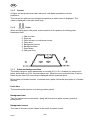
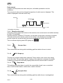
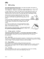
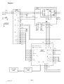
1
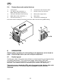
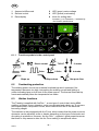
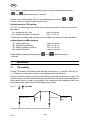
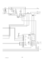
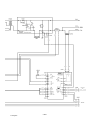
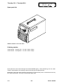
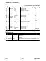
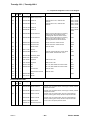
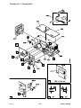
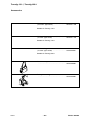
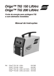
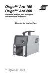
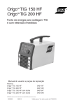
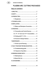
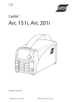
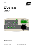
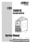
GB
Transtig 150- 1
Transtig 200- 1
Instruction manual and
spare parts list
0459 757 074
050526
Valid for serial no. 517--xxx--xxxx
1 DIRECTIVE . . . . . . . . . . . . . . . . . . . . . . . . . . . . . . . . . . . . . . . . . . . . . . . . . . . . . . . .
2 SAFETY . . . . . . . . . . . . . . . . . . . . . . . . . . . . . . . . . . . . . . . . . . . . . . . . . . . . . . . . . . .
3 INTRODUCTION . . . . . . . . . . . . . . . . . . . . . . . . . . . . . . . . . . . . . . . . . . . . . . . . . . .
3
3
4
3.1 Equipment . . . . . . . . . . . . . . . . . . . . . . . . . . . . . . . . . . . . . . . . . . . . . . . . . . . . . . . . . . . . . . . .
5
4 TECHNICAL DATA . . . . . . . . . . . . . . . . . . . . . . . . . . . . . . . . . . . . . . . . . . . . . . . . .
5
4.1 Settings . . . . . . . . . . . . . . . . . . . . . . . . . . . . . . . . . . . . . . . . . . . . . . . . . . . . . . . . . . . . . . . . . .
6
5 INSTALLATION . . . . . . . . . . . . . . . . . . . . . . . . . . . . . . . . . . . . . . . . . . . . . . . . . . . .
7
5.1
5.2
5.3
5.4
Placing . . . . . . . . . . . . . . . . . . . . . . . . . . . . . . . . . . . . . . . . . . . . . . . . . . . . . . . . . . . . . . . . . . .
Rating plate . . . . . . . . . . . . . . . . . . . . . . . . . . . . . . . . . . . . . . . . . . . . . . . . . . . . . . . . . . . . . . .
Mains power supply . . . . . . . . . . . . . . . . . . . . . . . . . . . . . . . . . . . . . . . . . . . . . . . . . . . . . . . .
Connections and control devices . . . . . . . . . . . . . . . . . . . . . . . . . . . . . . . . . . . . . . . . . . . .
7
7
7
8
6 OPERATION . . . . . . . . . . . . . . . . . . . . . . . . . . . . . . . . . . . . . . . . . . . . . . . . . . . . . . .
8
6.1 Control panel . . . . . . . . . . . . . . . . . . . . . . . . . . . . . . . . . . . . . . . . . . . . . . . . . . . . . . . . . . . . .
6.2 Overheating protection . . . . . . . . . . . . . . . . . . . . . . . . . . . . . . . . . . . . . . . . . . . . . . . . . . . . .
6.3 Hidden functions . . . . . . . . . . . . . . . . . . . . . . . . . . . . . . . . . . . . . . . . . . . . . . . . . . . . . . . . . .
8
9
9
7 WELDING . . . . . . . . . . . . . . . . . . . . . . . . . . . . . . . . . . . . . . . . . . . . . . . . . . . . . . . . . 10
7.1 TIG welding . . . . . . . . . . . . . . . . . . . . . . . . . . . . . . . . . . . . . . . . . . . . . . . . . . . . . . . . . . . . . . .
7.2 MMA welding . . . . . . . . . . . . . . . . . . . . . . . . . . . . . . . . . . . . . . . . . . . . . . . . . . . . . . . . . . . . .
10
14
8 WELDING DATA MEMORY . . . . . . . . . . . . . . . . . . . . . . . . . . . . . . . . . . . . . . . . . . 15
9 MAINTENANCE . . . . . . . . . . . . . . . . . . . . . . . . . . . . . . . . . . . . . . . . . . . . . . . . . . . . 16
10 FAULT TRACING . . . . . . . . . . . . . . . . . . . . . . . . . . . . . . . . . . . . . . . . . . . . . . . . . . . 16
10.1 Fault codes . . . . . . . . . . . . . . . . . . . . . . . . . . . . . . . . . . . . . . . . . . . . . . . . . . . . . . . . . . . . . . .
17
11 ORDERING SPARE PARTS . . . . . . . . . . . . . . . . . . . . . . . . . . . . . . . . . . . . . . . . . .
DIAGRAM . . . . . . . . . . . . . . . . . . . . . . . . . . . . . . . . . . . . . . . . . . . . . . . . . . . . . . . . . . . .
DIAGRAM . . . . . . . . . . . . . . . . . . . . . . . . . . . . . . . . . . . . . . . . . . . . . . . . . . . . . . . . . . . .
SPARE PARTS LIST . . . . . . . . . . . . . . . . . . . . . . . . . . . . . . . . . . . . . . . . . . . . . . . . . . .
ACCESSORIES . . . . . . . . . . . . . . . . . . . . . . . . . . . . . . . . . . . . . . . . . . . . . . . . . . . . . . .
17
18
20
22
29
Rights reserved to alter specifications without notice.
TOCe
-- 2 --
GB
1
DIRECTIVE
DECLARATION OF CONFORMITY
Murex Welding Products Ltd, EN8 7TF England, gives its unreserved guarantee that welding power
source Transtig 150--1 and Transtig 200--1 from serial number 517 complies with standards
EN 60974--1/--3, in accordance with the requirements of directive (72/23/EEC) and addendum
(93/68/EEC) and with standard EN 50199 in accordance with the requirements of directive
(89/336/EEC) and addendum (93/68/EEC).
--------------------------------------------------------------------------------------------------------------------------------------
On behalf of Murex Welding Products Ltd.
Laxå 2005--05--25
Henry Selenius
Managing Director
ESAB AB, Welding Equipment
SE--695 81 LAXÅ
SWEDEN
Tel: + 46 584 81000
Fax: + 46 584 411924
Manufactured by ESAB AB, Welding Equipment
SE--695 81 Laxå Sweden
2
SAFETY
Users of welding equipment have the ultimate responsibility for ensuring that anyone who works on
or near the equipment observes all the relevant safety precautions. Safety precautions must meet
the requirements that apply to this type of welding equipment. The following recommendations
should be observed in addition to the standard regulations that apply to the workplace.
All work must be carried out by trained personnel well--acquainted with the operation of the welding
equipment. Incorrect operation of the equipment may lead to hazardous situations which can result
in injury to the operator and damage to the equipment.
1.
Anyone who uses the welding equipment must be familiar with:
S its operation
S location of emergency stops
S its function
S relevant safety precautions
S welding
2.
The operator must ensure that:
S no unauthorized person is stationed within the working area of the equipment when it is
started up.
S no--one is unprotected when the arc is struck
3.
The workplace must:
S be suitable for the purpose
S be free from drafts
4.
Personal safety equipment
S Always wear recommended personal safety equipment, such as safety glasses, flame--proof
clothing, safety gloves.
S Do not wear loose--fitting items, such as scarves, bracelets, rings, etc., which could become
trapped or cause burns.
5.
General precautions
S Make sure the return cable is connected securely.
S Work on high voltage equipment may only be carried out by a qualified electrician.
S Appropriate fire extinquishing equipment must be clearly marked and close at hand.
S Lubrication and maintenance must not be carried out on the equipment during operation.
bt28d1e
-- 3 --
GB
WARNING
ARC WELDING AND CUTTING CAN BE INJURIOUS TO YOURSELF AND OTHERS. TAKE PRECAUTIONS WHEN WELDING. ASK FOR YOUR EMPLOYER’S SAFETY PRACTICES WHICH SHOULD BE
BASED ON MANUFACTURERS’ HAZARD DATA.
ELECTRIC SHOCK -- Can kill
S
Install and earth the welding unit in accordance with applicable standards.
S
Do not touch live electrical parts or electrodes with bare skin, wet gloves or wet clothing.
S
Insulate yourself from earth and the workpiece.
S
Ensure your working stance is safe.
FUMES AND GASES -- Can be dangerous to health
S
Keep your head out of the fumes.
S
Use ventilation, extraction at the arc, or both, to take fumes and gases away from your breathing zone
and the general area.
ARC RAYS -- Can injure eyes and burn skin.
S
Protect your eyes and body. Use the correct welding screen and filter lens and wear protective
clothing.
S
Protect bystanders with suitable screens or curtains.
FIRE HAZARD
S
Sparks (spatter) can cause fire. Make sure therefore that there are no inflammable materials nearby.
NOISE -- Excessive noise can damage hearing
S
Protect your ears. Use earmuffs or other hearing protection.
S
Warn bystanders of the risk.
MALFUNCTION -- Call for expert assistance in the event of malfunction.
READ AND UNDERSTAND THE INSTRUCTION MANUAL BEFORE INSTALLING OR OPERATING.
PROTECT YOURSELF AND OTHERS!
WARNING!
Read and understand the instruction manual before installing
or operating.
We can provide you with all necessary welding protection and accessories.
WARNING!
Do not use the power source for thawing frozen pipes.
This product is solely intended for arc welding.
3
INTRODUCTION
The Transtig 150-- 1 and Transtig 200-- 1 are welding current power sources based
on the static converter technology intended TIG welding and welding with coated
electrodes (MMA). Advanced electronics with microcomputer control produces e.g.
rapid regulation and top--class welding properties.
bt28d1e
-- 4 --
GB
3.1
Equipment
The Transtig is supplied with 3 m of mains cable and an instruction manual.
ESAB’s accessories for the product can be found on page 29.
4
TECHNICAL DATA
Mains voltage
Fuse (delayed--action)
Primary current Imax
Primary current Ieff
Voltage/current range
(TIG)
(MMA)
Maximum permissible load at TIG
25% duty cycle
35% duty cycle
60% duty cycle
100% duty cycle
Maximum permissible load at MMA
25% duty cycle
35% duty cycle
60% duty cycle
100% duty cycle
Power factor at maximum current
Efficiency at maximum current
Open--circuit voltage
Operating temperature
Constant A--weighed sound
pressure
Dimensions, l x b x h
Weight
Enclosure class
Application class
Transtig 150--1
230V, 1∼ 50/60 Hz
16 A
36 A
21 A
Transtig 200--1
230V, 1∼ 50/60 Hz
16 A
36 A
21 A
3 A / 10 V --150 A / 16 V
4 A / 20 V --150 A / 26 V
3 A / 10 V -- 200 A / 18 V
4 A / 20 V -- 150 A / 26 V
150 A / 16 V
120 A / 15 V
95 A / 14 V
200 A / 18 V
180 A / 17 V
140 A / 15,5 V
110 A / 14,5 V
150 A / 26 V
140 A / 25,5 V
110 A / 24,5 V
90 A / 23,5 V
150 A / 26 V
140 A / 25,5V
110 A / 24,5V
90 A / 23,5V
0,62
77 %
71 -- 78 V
--10˚C -- + 40˚C
<70 db
0,62
79 %
71 -- 78 V
--10˚C -- + 40˚C
<70 db
394 x 267 x 274 mm
10 kg
IP 23C
394 x 267 x 274 mm
10 kg
IP 23C
Duty cycle
The duty cycle refers to the time as a percentage of a ten--minute period that you can weld at a certain load without overloading.
Enclosure class
The IP code indicates the enclosure class, i. e. the degree of protection against penetration by solid
objects or water. Equipment marked IP23 is designed for indoor and outdoor use.
Application class
The symbol
indicates that the power source is designed for use in areas with increased
electrical hazard.
bt28d1e
-- 5 --
GB
4.1
Settings
4.1.1
TIG welding without pulsing
Settings
Setting range
In steps of:
Default value
Welding method
TIG, TIG pulse or MMA --
TIG
2/4 stroke *
2 stroke or 4 stroke
--
2 stroke
HF / LiftArct *
HF or Liftarct
--
LiftArct
Gas pre--flow
0 -- 5 s
0.1 s
0.5 s
Slope up time
0 --10 s
0.1 s
0.0 s
Slope down time
0 --10 s
0.1 s
1.0 s
Gas post--flow
0 -- 25 s
0.1 s
2.0 s
Current
Transtig 150--1
3 --150 A
1A
60 A
Current
Transtig 200--1
3 --200 A
1A
60 A
In steps of:
Default value
4.1.2
TIG welding with pulsing
Settings
Setting range
Welding method *
TIG, TIG pulse or MMA --
TIG
2/4 stroke *
2 stroke or 4 stroke
--
2 stroke
HF / LiftArct *
HF or Liftarct
--
LiftArct
Gas pre--flow
0 -- 5 s
0.1 s
0.5 s
Slope up time
0 -- 10 s
0.1 s
0.0 s
Slope down time
0 -- 10 s
0.1 s
1.0 s
Gas post--flow
0 -- 25 s
0.1 s
2.0 s
Pulse time
Micro pulse**
0.1 -- 2.5 s
0.001 -- 0.250 s
0.01 s
0.001 s
1.0 s
Background time
Micro pulse**
0.1 -- 2.5 s
0.001 -- 0.250 s
0.01 s
0.001 s
1.0 s
Pulse current
Transtig 150--1
3 -- 150 A
1A
60 A
Background current Transtig 150--1
3 -- 150 A
1A
20 A
Pulse current
Transtig 200--1
3 -- 200 A
1A
60 A
Background current Transtig 200--1
3 -- 200 A
1A
20 A
Settings
Setting range
In steps of:
Default value
Welding method
TIG / MMA
--
TIG
Arc Force
0 -- 99%
1%
5%
Drop welding
I/0
--
0
Regulator type ArcPlust
I/0
--
I
Hot start
0 -- 99%
1%
0%
4.1.3
MMA settings
Current
Transtig 150--1
4 -- 150 A
2A
100 A
Current
Transtig 200--1
4 -- 150 A
2A
100 A
*) These functions cannot be changed while welding is in progress.
**) Gas pre--flow time and micro pulse are hidden functions, see page 9 .
bt28d1e
-- 6 --
GB
5
INSTALLATION
WARNING!
This product is intended for industrial use. In a domestic environment this product may cause radio
interference. It is the user’s responsibility to take adequate precautions.
5.1
Placing
Place the power source so that its cooling air inlets and outlets are not obstructed.
5.2
Rating plate
The rating plate is located on the rear side of the power source.
5.3
Mains power supply
Make sure that the welding power source is connected to the correct supply voltage
and that it is protected by the correct fuse rating. The standards for the country in
question must be complied with as regards the mains cable area. A protective earth
connection must be made in accordance with regulations.
5.3.1
Recommended fuse sizes and minimum cable areas
Mains voltage
Mains frequency
Fuse (delayed--action)
85A 35% duty cycle MMA
120A 20% duty cycle MMA
150A 25% duty cycle MMA
Mains cable, area
Welding cable, area MMA
Welding cable, area TIG
Transtig 150--1
Transtig 200--1
230 V ¦10 %, 1--phase
230 V ¦10 %, 1--phase
50--60 Hz
50--60 Hz
10 A
16 A
20 A*)
10 A
16 A
20 A*)
3 x 2.5 mm2
3 x 2.5 mm2
mm2
16
16 mm2
*) NOTE! The mains plug is approved for maximum 16A.
bt28d1e
-- 7 --
16 mm2
25 mm2
GB
5.4
Connections and control devices
1
Control panel
6
Connection for the TIG torch switch
2
TIG: Return cable connection (+)
MMA: Welding cable connection (--)
7
Remote control unit connection
3
Gas hose connection to the TIG torch
8
Mains power supply switch
4
MMA: Return cable connection (--)
9
Mains cable
5
TIG torch connection (--)
10
Connection for shielding gas
2 and 4 are used for welding current supply and return cable connection during MMA welding
6
OPERATION
General safety regulations for the handling of the equipment can be found on
page 3. Read through before you start using the equipment!
6.1
Control panel
On the upper side of the power source there is a control panel for choosing functions
and setting parameters. This comprises a display, setting knob, LEDs and
pushbuttons. Using the pushbuttons, it is possible to move between the various
functions. The selected function is indicated by the relevant LED lighting up.
The power source checks the LEDs and all segments in the display when main
switch is turned on. The machine type and program version are also
displayed.
bt28d1e
-- 8 --
GB
1
3
Ampere/volt/Seconds
Remote control
2
4
5
Data display
6
6.1.1
Knob for setting data.
Increase (+) or Decrease (--) selected by
the function pushbuttons
Function symbols in the control panel
TIG
Direct current
MMA
Pulse
Slope up
6.2
LED (green) mains voltage
LED (yellow) overheating
TIG HF
LiftArc
Slope down
2 stroke
4 stroke
Gas post-- flow
Overheating protection
The welding power source has a thermal overload trip which operates if the
temperature becomes too high, interrupting the welding current and lighting a
yellow indicating lamp on the front of the power source. The thermal overload trip
resets automatically when the temperature has fallen.
6.3
Hidden functions
The Transtig is supplied with ArcPlust, a new type of control that, during MMA
welding, produces a more intensive, more concentrated and calmer arc. It recovers
more quickly after a drop short--circuit, which reduces the risk of the electrode
becoming caught.
The machine is also equipped with Arc Force, which means that the power source’s
dynamics can be adjusted, softer or harder depending on the type of electrode and
according to preference. However, the Arc Plust regulator’s good properties mean
that there is only reason to alter the Arc Force setting in exceptional cases.
bt28d1e
-- 9 --
GB
The Transtig includes additional setting options that are obtained by pressing
and
simultaneously for 1 second.
Access to the setting options (A --H) are displayed by pressing
Set the values or function by turning the knob.
or
.
Hidden functions TIG welding
For TIG, the following options under the double press function can be found under
the letters:
A = setting gas pre--flow
b = setting micropulse (TIG pulse
time in seconds
Off= 0 or On=1
The following welding data setting options for MMA can be found under the letters:
Hidden functions MMA welding
C = setting ArcForce
d = setting Drop welding
F = setting regulator ArcPlust
H = setting Hot Start
Reset additional settings by pressing
1 second.
7
WELDING
7.1
TIG welding
value in percent
Off=0 or On =1
Off=1 or On =0
value in percent
and
simultaneously for
During TIG welding, the return cable must be connected to (+) and the TIG torch to
(--). If they are connected in reverse, the tungsten electrode will melt.
Pulsing is used for improved control of the weld pool and the solidification process. The
pulse frequency is set so slow that the weld pool has time to solidify at least partially between each pulse. In order to set pulsing, four parameters are required: pulse time,
background time, pulse current and background current.
7.1.1
2 stroke
Gas pre--flow
Slope
up
Slope down
Functions when using 2 stroke control of the welding torch.
bt28d1e
-- 10 --
Gas post-flow
GB
In the 2 stroke control mode, pressing the trigger switch starts gas pre--flow (if used)
and strikes the arc (1). The current rises to the set value (as controlled by the slope
up function, if in operation). Releasing the trigger switch (2) reduces the current (or
starts slope down if in operation) and extinguishes the arc. Gas post--flow follows if it
is in operation.
7.1.2
4 stroke
Gas pre--flow
Slope
up
Slope down
Gas post-flow
Functions when using 4 stroke control of the welding torch.
In the 4 stroke control mode, pressing the trigger switch starts gas pre--flow (if used)
(1). At the end of the gas pre--flow time, the current rises to the pilot level (a few
ampere), and the arc is struck. Releasing the trigger switch (2) increases the current
to the set value (with slope up, if in use). At the end of welding, the welder presses
the trigger switch again (3), which reduces the current to pilot level again (with slope
down, if in use). Releasing the switch again (4) extinguishes the arc and starts gas
post--flow.
7.1.3
HF
The HF function strikes the arc by means of a spark from the electrode to the
workpiece as the electrode is brought closer to the workpiece.
7.1.4
LiftArct
The Lift Arct function strikes the arc when the electrode is brought into contact with
the workpiece and then lifted away from it.
Striking the arc with the Lift Arc function. Step 1: the electrode is touched on to the workpiece. Step 2:
the trigger switch is pressed, and a low current starts to flow. Step 3: the welder lifts the electrode
from the workpiece: the arc strikes, and the current rises automatically to the set value.
bt28d1e
-- 11 --
GB
7.1.5
Current
A higher current produces a wider weld pool, with better penetration into the
workpiece.
The current set value can be changed irrespective of which menu is displayed. This
value is displayed in the main menu only.
7.1.6
Pulse
When activating pulse, the power source must be in the position for setting pulse
time/pause time.
1. Gas pre--flow
2. Slope up
3. Pulse current or continuous current
4. Pulse time
5. Background current
6. Background time
7. Slope down
8. Gas post--flow
7.1.7
Pulse and background time
The setting range for these parameters is normally 0.01--2.5 s. However, by using micro
pulse, times down to 0.001 seconds can be set. When the micro pulse function is active,
times shorter than 0.25 seconds are displayed without a decimal point.
Micro pulse is a hidden function, to activate micro pulse, follow the description 6.3 “Hidden
function”.
Pulse time
The time the pulse current is on during a pulse period.
Background time
Time for background current which, along with the time for pulse current, gives the
pulse period.
Background current
The lower of the two current values in the event of pulsed current.
bt28d1e
-- 12 --
GB
Pulse current
A higher current produces a wider weld pool, with better penetration into the
workpiece.
The current set value can be changed irrespective of which menu is displayed. This
value is displayed in the main menu only.
Current
Background
time
Pulse current
Background
current
Pulse time
Time
TIG welding with pulsing.
7.1.8 Remote control unit
Using the remote control unit socket on the machine, the current can be controlled remotely
for both TIG and MMA.
If pulsed current is chosen in TIG mode, it is the pulse current that is remotely controlled.
The value set from the remote control unit is shown on the display by browsing to the
position where the current would have been set without the remote control unit.
This is confirmed by the green LED lighting up.
7.1.9
Gas pre-- flow
This controls the time during which shielding gas flows before the arc is struck.
7.1.10
Slope up
The slope up function means that, when the TIG arc strikes, the current rises slowly
to the set value. This provides ‘gentler’ heating of the electrode, and gives the welder
a chance to position the electrode properly before the full current value is reached.
7.1.11
Slope down
TIG welding uses slope down, by which the current falls ’slowly’ over a controlled
time, to avoid craters and/or cracks when a weld is finished.
7.1.12
Gas post--flow
This controls the time during which shielding gas flows after the arc is extinguished.
bt28d1e
-- 13 --
GB
7.2
MMA welding
The Transtig gives direct current, and you can weld most metals to alloy and non-alloy steel, stainless steel and cast iron.
The Transtig 150--1 allows you to weld most coated electrodes from ∅ 1.6 to ∅ 3.25.
The Transtig 200--1 allows you to weld most coated electrodes from ∅ 1.6 to ∅ 4.0.
If, when striking the arc, the tip of the electrode is pressed against the metal, it immediately melts and sticks to the metal, rendering continued welding impossible.
Therefore, the arc has to be struck in the same way that you would light a match.
Quickly strike the electrode against the metal, then raise it so
as to give an appropriate arc length (approx. 2 mm). If the arc
is too long, it will crackle and spit before finally going out completely.
If you are working on a welding bench, check before attempting
to strike the arc that residual waste metal, pieces of electrode
or other objects on the bench do not insulate the part to be
welded.
cmha2p11
Once the arc has been struck, move the electrode from left to
right. The electrode must be at an angle of 60˚ to the metal in
relation to the direction of welding.
When you want to weld wide beads, or when you want the weld
to be so thick that you have to weld in a number of layers, however, you have to use lateral movements.
7.2.1
cmha2p10
Setting regulator - ArcPlust
The Transtig is supplied with ArcPlust, a new type of control that, during MMA
welding, produces a more intensive, more concentrated and calmer arc. It recovers
more quickly after a drop short--circuit, which reduces the risk of the electrode
becoming stuck.
7.2.2
Arc Force
The Arc Force setting alters the machine’s dynamics. A softer/harder arc can be obtained.
The arc force is important in determining how the current changes in response to a change
in the arc length. A lower value gives a calmer arc with less spatter.
7.2.3
Drop welding
Drop welding can be used when welding with stainless electrodes.
This technique involves alternately striking and extinguishing the arc in order to achieve
better control of the supply of heat. The electrode needs only to be raised slightly to
extinguish the arc.
7.2.4
Hot Start
Hot start increases the weld current for an adjustable time at the start of welding,
thus reducing the risk of poor fusion at the beginning of the joint.
bt28d1e
-- 14 --
GB
8
WELDING DATA MEMORY
The Transtig can store 4 different welding data setups in the machine’s memory, divided between 2 in TIG mode and 2 in MMA mode.
The following can be stored:
In TIG mode
all settings can be stored.
In MMA mode
only welding current can be stored.
For setting gas pre--flow, TIG MicroPulse, ArcForce and drop welding:
Press button
or
for 5 seconds to store the data in the memory. At the beginning the green LED shines constantly, and then starts flashing when the data has
been saved.
To switch between the predefined settings, use button
or
Change settings with the torch trigger by pressing
.
Press the torch trigger quickly (within 0,3 seconds) to switch between the stored settings.
The Transtig has a back--up battery so that the settings remain even if the machine
has been switched off or disconnected from the mains.
bt28d1e
-- 15 --
GB
9
MAINTENANCE
Regular maintenance is important for safe, reliable operation.
Note!
All guarantee undertakings from the supplier cease to apply if the customer himself
attempts any work in the product during the guarantee period in order to rectify any
faults.
The Transtig requires little maintenance. In normal cases, it is sufficient to blow it
clean using dry compressed air once a year, but this should be done more often if it
is set up in a dusty, dirty area.
10
FAULT TRACING
Try these recommended checks and inspections before sending for an authorised
service technician.
Type of fault
No arc.
Action
S
S
S
The welding current is interrupted during welding.
S
S
The thermal overload trip opera- S
tes frequently.
S
Poor welding performance.
S
S
S
S
bt28d1e
Check that the mains power supply switch is turned on.
Check that the welding current supply and return cables are
correctly connected.
Check that the correct current value is set.
Check whether the thermal overload trips have operated
(indicated by the yellow lamp on the front panel).
Check the main power supply fuses.
Make sure that you are not exceeding the rated data for the
welding power source (i.e. that the unit is not being
overloaded).
Check that the dust filter is clean.
Check that the welding current supply and return cables are
correctly connected.
Check that the correct current value is set.
Check that the correct electrodes are being used.
Check the main power supply fuses.
-- 16 --
GB
10.1
Fault codes
The Transtig comes with built--in fault monitoring. If a fault occurs, a code is shown in
the display.
If any of these fault codes is displayed permanently or recurs often, the machine
should be sent to an authorised ESAB service workshop for repair.
Fault
Description
Resetting
Action
E1
Internal RAM fault
Restart the machine.
If the fault persists, contact a
service workshop
E2
External RAM fault
Restart the machine.
If the fault persists, contact a
service workshop
E3
EPROM fault
Restart the machine.
If the fault persists, contact a
service workshop
E4
Fault in RAM with battery
backup
Restart the machine.
If the fault persists, contact a
service workshop
E5
Memory error, variable value outside limits
Restart the machine.
If the fault persists, contact a
service workshop
E6
Low battery voltage
Reset by pressing a button
E10
+ 20V fault
(18.5 – 21.5 V)
Automatic reset once fault
has disappeared
E11
--15V fault
(--13.0 -- --16.0)
Automatic reset once fault
has disappeared
E13
High temperature
Automatic reset once fault
has disappeared
E14
Current servo fault
Automatic reset once fault
has disappeared Also reset
by pressing a button
E99
Bridging fault
The digital control card is
bridged in a non--defined
combination.
11
If the fault persists, contact a
service workshop
Restart the machine.
If the fault persists, contact a
service workshop
ORDERING SPARE PARTS
Repair and electrical work should be performed by an authorized serviceman.
Use only original spare and wear parts.
Transtig 150--1 and Transtig 200--1 are designed and tested in accordance with the
international and European standards EN 60974--1/--3 and EN 50199. It is the obligation
of the service untit which has carried out the service or repair work to make sure that
the product still conforms to the said standard.
bt28d1e
-- 17 --
Diagram
Transtig 150
-- 18 --
Transtig 150
-- 19 --
Diagram
Transtig 200
-- 20 --
Transtig 200
-- 21 --
Transtig 150- 1, Transtig 200- 1
Spare parts list
Valid for serial no. 517--xxx--xxxx
Ordering number
0459 760 893 Transtig 150--1 for 230 V mains voltage
0459 760 894 Transtig 200--1 for 230 V mains voltage
Spare parts are to be ordered through the nearest MUREX agency. Kindly indicate type of unit, serial
number, denominations and ordering numbers according to the spare parts list.
Maintenance and repair work should be performed by an experienced person, and electrical work only
by a trained electrician. Use only recommended spare parts.
bt28s1
-- 22 --
Edition 050526
Transtig 150- 1, Transtig 200- 1
C = component designation in the circuit diagram
Item
Qty
Ordering no.
AA1
1
0459 654 001
AA2
2
AA3
1
AA4
4
Screw
M5x12
AA5
1
Screw
M5x16 Included in item AB51, see page 24.
bt28saa1
Denomination
C
Handle
Screw
0459 173 002
Notes
M8x50
Cover
-- 23 --
Edition 050526
Transtig 150- 1, Transtig 200- 1
C = component designation in the circuit diagram
Item
Qty
Ordering no.
AB1
1
0193 317 001
AB2
1
AB3
Denomination
Notes
Switch
Included in item AB50
Cord set
Included in item AB50
Screw
Included in item AB51 and AB53
2QF1
AB4
1
0459 174 001
Rear panel
AB5
1
0487 018 880
Display board
Included in item AB51
AB6
1
Front panel
Included in item AB51 and AB53
AB7
1
Control Panel
Included in item AB51
AB8
1
0321 475 893
Knob
Included in item AB51
AB9
5
0366 588 001
Nut
AB10
0366 306 883
Spacer
Included in item AB51
Connector OKC 25
Included in item AB51
C
1AP2
1AP1
AB11
3
29XS1, 29XS2,
29XS3
AB12
3
Screw
M5x12 Torx. Included in item AB51
AB13
1
Cable shoe
Included in item AD4, see page 28
AB14
1
0459 194 003
Busbar, positive
AB15
1
0459 194 002
Busbar, negative
AB16
1
0194 130 120
Nut
Included in item AB51
AB17
1
0459 269 001
Gas connection
Included in item AB51
AB18
1
Socket
Included in item AB52
29XS4, 29xS5
SPARE PARTS SETS
Item
Ordering no.
AB50
0459 183 880
Mains module
Includes items: AB1 switch, AB2 mains cable with plug, cable clamp and two
ferrite rings 2L1.
AB51
0459 386 888
Front complete, TIG
Includes items: AA5, AB3, AB5, AB6, AB7, AB8, AB10, AB11, AB12, AB16,
AB17, AB18
AB52
0459 280 885
Cable set
2 pole socket 29XS4, 5 pole socket 29XS6, 1 pole socket 29XS8 and the wires
between them.
bt28sab1
Denomination
Notes
-- 24 --
Edition 050526
Transtig 150- 1, Transtig 200- 1
bt28sab1
-- 25 --
Edition 050526
Transtig 150- 1, Transtig 200- 1
C = component designation in the circuit diagram
Item
Qty
150
Qty
200
Ordering no.
AC1
1
1
0487 064 880
Power supply board
AC2
1
1
0459 280 880
Cable set
Including wires 1501, 1502 and their
sockets
15XS1, 15XS2,
15XS7, 15XS8
AC2
1
1
0459 280 880
Cable set
Including wires 1501, 1502 and their
sockets
15XS1, 15XS2,
15XS7, 15XS8
1
1
0193 700 702
Cable set
20XS3, 20XS4
1
1
0459 280 881
Cable set
20XS1, 20XS2,
20XS5
AC3
1
1
0459 390 880
Control board kit
Before mounting the board, the strapping
must be set up to fit CaddyTig 150 or
CaddyTig 200. See the service manual.
20AP1
AC3
1
1
0459 390 880
Control board kit
Before mounting the board, the strapping
must be set up to fit OrigoTig 150 or
OrigoTig 200. See the service manual.
20AP1
AC4
1
0468 940 004
Thermal switch
Socket connector 15XS5 included
15ST2
0468 940 005
Thermal switch
Socket connector 15XS5 included
15ST2
Diode module
See item AC50
15D1
1
Denomination
Notes
C
2AP1
AC5
1
1
AC6
1
1
0459 177 001
Inductor
AC7
1
1
0459 355 880
Transformer
0487 060 880
Secondary board
0459 273 001
Earth bracket
0194 158 001
Capacitor
1000 uF 400 V DC
15C1
0194 158 002
Capacitor
2000 uF 400 V DC
15C1
0467 801 002
Fan
24 V DC; With cables and socket 15XS3
15EV1
0458 065 002
Fan
24 V DC; With cables and socket 15XS3
15EV1
15AP1
AC8
AC9
1
AC10
1
1
1
AC11
1
AC11
1
15L1
Includes: main transformer, socket 15XS4,
socket 15XS6, thermal switch 15ST1
15TM1
15AP2
AC12
1
1
Circuit board
See item AC51
AC13
1
1
Semiconductor module
See item AC51
AC14
1
1
0468 030 880
Shunt
AC15
1
1
0459 194 001
Busbar
15RS1
SPARE PARTS SETS
Item
Qty
150
AC50
1
Qty
200
Ordering no.
Denomination
Notes
0459 385 880
Diode module kit
Includes: item AC5 diode module, screws (type A and B), thermal
compound and roller.
0459 385 881
Diode module kit
Includes: item AC5 diode module, screws (type A and B), thermal
compound and roller.
0459 384 880
Power board kit
Includes: item AC12 power board, item AC13 semiconductor
module, screws (type A and B), thermal compound and roller.
0459 384 881
Power board kit
Includes: item AC12 power board, item AC13 semiconductor
module, screws (type A and B), thermal compound and roller.
--
0458 910 002
Roller handle
For the roller in the spare parts sets above
--
0192 058 101
Thermal compound
1
AC51
1
1
bt28sac1
-- 26 --
Edition 050526
Transtig 150- 1, Transtig 200- 1
bt28sac1
-- 27 --
Edition 050526
Transtig 150- 1, Transtig 200- 1
C = component designation in the circuit diagram
Item
Qty
Ordering no.
AD1
1
0193 054 005
Solenoid valve
AD2
1
0194 130 120
Nut
AD3
1
0456 496 001
Hose
AD4
1
0487 028 880
Circuit board TIG
10AP1
AD5
1
0459 389 880
HF coil, complete
10TV1, 10XS1
bt28sad1
Denomination
Notes
230 V AC
C
10YV1
D = 9/5 mm, L = 0.57 metre reinforced PVC
-- 28 --
Edition 050526
Transtig 150- 1, Transtig 200- 1
Accessories
MMA welding and return cable kit
(”crocodile” type holder) . . . . . . . . . . . . . . . . 0349 501 078
Suitable for Transtig 150--1
MMA welding and return cable kit
(”screwe” type holder) . . . . . . . . . . . . . . . . . 0349 501 079
Suitable for Transtig 150--1
MMA welding and return cable kit
(”screwe” type holder) . . . . . . . . . . . . . . . . . 0700 006 881
Suitable for Transtig 200--1
Shoulder strap
. . . . . . . . . . . . . . . . . . . . . . . . . . . . . . . . . . . . 0459 368 880
Trolley for small gas bottle
. . . . . . . . . . . . . . . . . . . . . . . . . . . . . . . . . . . . 0459 366 880
bt28acc
-- 29 --
Edition 050526
p
-- 30 --
p
-- 31 --
Murex Welding Products Ltd
Hanover House
Queensgate
Britannia Road
Waltham Cross
Hertfordshire EN8 7TF
England