1
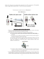
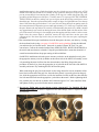
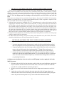
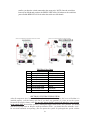
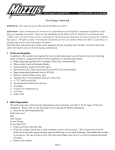
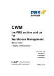
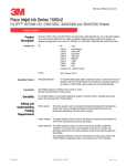
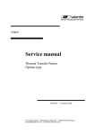
POWERSPORTS SYSTEMS WITH ELECTRIC INLINE FUEL PUMP
POWER SPORTS TECH LINE 877-648-7687
CONGRATULATIONS
You have purchased the most technologically advanced, researched, field-tested, state of the art nitrous
system manufactured to date! The most important thing to do now is to:
READ...UNDERSTAND...AND FOLLOW
these instructions. If there is something you don’t understand STOP.... Call the factory tech department
for help. 1-877-648-7687 Mon-Fri, 9AM-5PM PST.
CAUTION
Adding a NX Nitrous system to your Power Sport machine is a job best handled by a professional
mechanic with nitrous oxide installation experience, Nitrous Express Inc. urges you to seek professional
help on all installation procedures.
Absolutely do not mix any other brand components, of any kind, with your NX system. Using noncompatible parts or accessories will void your warranty. Using non-compatible, mismatched parts can
create a dangerous or potentially fatal event.
Nitrous Express Inc. instructions are as complete as possible, however every possibility cannot be
covered in this instruction sheet, if you have any problem or question, STOP and call the NX tech line for
help, 1-877-648-7687.
The installation procedures are divided into five sections.
Please pay particular attention to each one.
1. Mounting the Bottle.
2. Installing the nitrous nozzles.
3. Plumbing the fuel system.
4. Testing the system.
5. Tuning tips.
Before starting any installation steps, disconnect the negative battery terminal, and drain all fuel from the
vehicle including the carburetors.
1
SECTION 1: MOUNTING THE BOTTLE
The bottle should be mounted in the storage area or away from the operator. The best positioning of
the bottle is shown in illustration “A”. Mounting the bottle in this manner will allow the bottle valve or
internal siphon tube to be covered with liquid nitrous at all times and properly supports the bottle.
Assemble the brackets on the bottle; refer to the chart below to determine the suggested bracket spacing.
Bottle Size
Distance to
Short/Bottom
Bracket
Distance to
Tall/Top
Bracket
Billet Bracket Part
Number
Contains Siphon
Tube
3.5 Oz
1”
3”
11013P/11017P
NO
7 Oz
1 ¼”
7”
11013P/11017P
NO
10 Oz
1 ¼”
10 ¾”
11013P/11017P
NO
1 LB
1 ¼”
5 ½”
11029P
YES
1 1/4 LB
1 ¼”
6 ½”
11029P
YES
2 LB
1 ¼”
6”
11018P
YES
2.5 LB
1 ¼”
7 ½”
11018P
YES
5 LB
1 ¼”
10 ½”
11031
YES
10 LB
2 ¾”
11 ¾”
11108/11108B
YES
15 LB
2 ¾”
15 ¾”
11108/11108B
YES
This assembly will serve as a guide to locate the four mounting holes. The bottle brackets should be
secured by grade 5 bolts and washers. Before drilling the holes be sure to check for clearance beneath the
mounting surface, i.e.: fuel tank, fuel lines, and brake lines. Each dimension given above is from the
bottom of the bottle to the center of the bracket, a 10% variance in spacing, if necessary, is acceptable.
Bracket spacing is especially critical when a bottle is mounted on an ATV or motorcycle, or when
installed “standing up” (upright position). Bottles mounted with the brackets in or near the middle will
oscillate causing metal fatigue resulting in bracket failure. Billet brackets are suggested for installations
on ATV and motorcycles, or any vehicles used in rough terrain or where band style clamps allow
vibration or oscillation to occur. If band style brackets are used a minimum of two brackets must be
installed on systems that use a 7oz bottle or larger. Nitrous Express does not recommend the mounting of
2
bottles to the swing arm or any portion of the suspension of an ATV or motorcycles. SCTA and BNI
require an approved blow down tube (PN 11711P) on all motorcycle installations.
The bottle must be mounted as shown in “Illustration A”.
ILLUSTRATION A
SECTION 2: INSTALLING THE NOZZLE
1. Remove all parts necessary to gain access to the intake ports or allow removal of the intake
manifold(s). Refer to the factory service manual if necessary.
2. Determine the best location for the nozzle(s) keeping in mind the following:
A. The nozzle must be installed between the carb(s) or throttle bodies and the engine.
B. You will need to be able to remove and install the braided hoses to the jet fittings on
the nozzle.
C. The nozzle(s) can be installed in the rubber boot between the carb(s) and the engine if
the boot has enough space between the clamps.
D. The nozzle(s) must be aimed to spray the nitrous and fuel into the engine in line with
the airflow through the port, not against the side or wall of the port. (Exception: On
single nozzle installation in V-twins the nozzle is aimed toward the center of the
manifold, see Illustration B)
ILLUSTRATION B
F. On multiple cylinder installations the nozzle locations only need to be similar, they do
not have be exactly all the same. This will allow for clearance around cam chain
tensioners, water outlets, etc. (see Illustration C)
3. Once the appropriate location is determined drill a 3/16” pilot hole to verify the location. Then
drill the hole to ¼”. If the nozzle is to be installed in the rubber intake you do not need to tap
the hole, simply thread the nozzle into the hole and seal with a RTV type sealer. If you are
3
installing the nozzle in the cylinder head make sure the cylinder you are working on is at TOP
DEAD CENTER (check with service manual for any questions) then place a rag or rags in the
port to prevent debris from entering the cylinder (if the rags are coated with grease they will
get almost all the fillings out of the port). Carefully start a 1/16-npt tap (NOT INCLUDED IN
THE SYSTEM) in the hole, making sure you are square to the hole (being careful not to cross
thread the tap). Once the tap has started add a couple of drops of a light lubricant. Turn the tap
about 2 full turns then go back about 1/3 of a turn, this will keep the tap from getting stuck on
the removed material. Repeat the process until approximately 1/4” of the tap is exposed inside
the port. Remove the tap and test fit a nozzle, when threading the nozzle in by hand it should
stop approximately two turns from having the start of the threads flush with the surface of the
port. If the nozzle will not go in far enough repeat the tapping until the nozzle is at the correct
depth. Once the correct depth is achieved, remove the rags) and blow out the port with
compressed air. Put clean rags back in the port and move on to the next port, repeating the
procedure.
4. On conventional direct port installations select the horsepower increase you desire by viewing
the chart found in the jet bag. (see page 6 for MOTO 4 nozzle plumbing) Select the indicated
jets and insert the jets into the nozzle, the nozzle is marked “Nitrous”& “Fuel” for your
convenience. Connect the stainless braided lines, RED FOR FUEL, BLUE FOR NITROUS, to
the nozzle and route them to solenoids. Using the provided brackets, mount the solenoid in a
central location that allows the proper routing of the braided lines.
On MOTO 4 installations select the power increase you desire on the included jet card, place
the appropriate nitrous jet in the jet holder on the nitrous side of the MOTO 4 assembly, secure
it by attaching the main feed line from the nitrous bottle to the fitting. Repeat the same
procedure for the fuel jet, place the appropriate jet in jet holder in the fuel side of the MOTO 4
assembly and secure it by attaching the fuel line from the pump.
When connecting the poly line to the nozzle see the image below for correct orientation of the
brass ferrule on the end of the poly line. Once the brass ferrule is correctly placed on the poly
line, slide the appropriate color B nut (red for fuel and blue for N20) on the line, then slide the
line with nut and ferrule into the appropriate jet holder on the nozzle. Before tightening the B
nut, push the poly line into the jet holder until it bottoms (approx 3/16”) then install the B nut
and tighten securely, repeat for all other nozzle connections.
5. Do not use Teflon tape on any nitrous system component!!! Use Supplied NX Red
Thread Sealer only!!! No sealer is required on AN flare fittings; sealer is required on pipe
style threads.
ILLUSTRATION C
4
SECTION 3A: PLUMBING THE FUEL SYSTEM WITH EXTERNAL PUMP
This is the most important section involved in the system installation. In all cases an adequate fuel
supply must be furnished to the fuel pump. On a carbureted street system a stock petcock is usually
adequate. On a carbureted competition system a Pingle style dual outlet petcock is required. On all fuel
injected applications, you must tap the fuel tank for your fuel supply to the included electric pump. (Do
not “T” off of the high pressure line leading to the fuel injectors; use PN15724P to tap your fuel
tank)
Most systems are designed to be used with a Nitrous Express fuel pump (PN 15005P). No fuel pressure
regulator is required, however: if a high volume aftermarket pump is used, a regulator is required. A fuel
filter is included with the Nitrous Express fuel pump.
1. Carbureted street systems are furnished with a “T” fitting that may be used to splice into the fuel line
supplying the carburetor. Route a rubber fuel line from this “T” fitting or fuel outlet to the inlet side of
the fuel pump, using the supplied hose and clamps. Run a line from the outlet side of the pump to the
fuel solenoid using the supplied hose and clamps. (The threaded female end of the fuel pump is the
inlet side; the brass barb or nipple is the outlet side.) A fuel filter is also included to be installed before
the pump on the threaded end. Use extreme caution when cutting and installing the rubber line to
prevent rubber debris from fouling the fuel solenoid or clogging the fuel jets. Do not allow either of
these lines to come in contact with the exhaust system or any moving parts i.e. suspension.
2. Competition bikes should route a line directly from the dual outlet petcock to the inlet side of the pump
using the supplied fuel line and clamps.
3. For added safety and reliability, a fuel pressure safety switch should be used. (PN 15708P). The switch
should be plumbed between the fuel pump and the fuel solenoid.
SECTION 3B: PLUMBING THE FUEL SYSTEM ON MOTO 4 SYSTEMS
On low pressure installations:
1. Locate an appropriate location for the pump; it needs to be below and behind the stock fuel
tank. The pump must be securely mounted away from any high heat source like the exhaust.
2. Using the supplied rubber hose and clamps connect the inlet (fuel filter) of the enclosed fuel
pump to the stock fuel petcock by using the supplied “T” fitting. If the stock petcock is
vacuum actuated, it will need to be replaced with a petcock that is not vacuum actuated.
3. Connect the outlet of the fuel pump to the inlet of the fuel solenoid by using the enclosed
rubber hose with the brass barbed fitting and red “B” nut, remember the fuel jet is positioned
at the inlet of the solenoid and held in place by the barbed brass fitting and the red ”B” nut
(see plumbing illustration)
On high pressure installations where the stock in tank EFI pump is used to supply the fuel to the
MOTO 4 system:
1. Disconnect the stock fuel line from the outlet on the fuel tank (on some installations a special tool
may be needed to disconnect the fuel line from the tank, it is the same as most late model EFI
cars and tool is readily available at most auto parts stores).
2. With the stock fuel line disconnected install the fuel line adaptor and reconnect the stock fuel
line.
3. Attach the correct hose with red ends to the outlet on the side of the fuel pump adaptor and
connect the other end to the fuel inlet fitting on the MOTO4 solenoid assembly after placing the
correct fuel jet based on the power level you select in the inlet of the fuel solenoid.
5
MOTO 4 PLUMBING ILLUSTRATION
POLY LINE TO NOZZLE ASSEMBLY ILLUSTRATION
SECTION 4: WIRING THE SYSTEM
The triggering mechanism for NX Power Sports systems is a mechanical wide-open throttle microswitch. Follow the wiring diagram in “Illustration D”. If using a TPS autolearn switch for your triggering
mechanism follow “Illustration E”. In all applications, always use the furnished relay, this will insure
adequate voltage to the solenoids and take the high amperage load off of the trigger switch.
PROGRAMMING a TPS Wide Open Throttle Module with two LEDs.
The NX TPAS is designed to trigger a relay, 1 amp maximum current draw, at or near wide open throttle
and automatically calibrates itself to work with rising or falling signal.
1. The NX TPS Wide Open Throttle Module should be mounted in a place that it will be easy to
access the learn button and view the LEDs. Make sure the unit is located away from any heat
source, i.e. exhaust manifold, header, or EGR.
2. Following the wiring diagram, route all wires but make no connections.
3. You must determine which wire on your throttle body’s TPS is the output signal to the vehicles
computer. Connect all wires per NX Self- Programming Throttle Position Activation Switch
wiring diagram using a 1 to 3 amp fuse in series with the red wire.
4. On initial power up, press and hold the button while turning on switched +12 volts. The green
LED should begin flashing indicating that the unit is not programmed.
5. Release the button.
6
6. With the throttle at idle position, press and hold the button until the red LED comes on
(approximately 4 seconds). The green LED will continue to flash. Release the button and leave
the throttle at Idle. The unit is now calibrating the idle position and making sure that the idle
signal is stable. Wait for both LED’s to turn off.
7. Now move throttle to wide open and hold for 1 second, then release back to idle (Red LED
should come on to indicate that its working and waiting to check the calibration).
8. To check the calibration, move throttle to wide open again and then release to idle a second time.
Once the check is complete, the Red LED will turn off and the Green LED will turn on indicating
that the unit is calibrated and armed.
9. Once calibrated, the unit will activate the relay when the throttle opens to 90% or more and it will
remain on as long as the throttle is between 90% and 100%. (When the relay is activated, both the
red and green LEDs will be on). When the throttle closes to less than 90%, the unit will turn the
relay and the red LED off. The green LED will remain on indicating that the unit is re-armed and
ready for the next run.
10. If at any time during the calibration process the green and red LED’s flash rapidly in an
alternating pattern that means the calibration was not completed correctly. This can be the result
of one of two things. Either the throttle was moved while it was calibrating the idle position or the
TPS signal is not stable. Check wiring and recalibrate.
PROGRAMMING a TPS Wide Open Throttle Module with one LED
The TPAS is designed to trigger a relay, 1 amp maximum current draw, at or near wide open throttle and
automatically calibrates itself to work with rising or falling signal.
1. The NX TPS Wide Open Throttle Module should be mounted in a place that it will be easy to
access the learn button and view the LEDs. Make sure the unit is located away from any heat
source, i.e. exhaust manifold, header, or EGR
2. Following the wiring diagram, route all wires but make no connections.
3. You must determine which wire on your vehicle’s TPS is the output signal to the vehicles
computer. Refer to your vehicle’s service manual to determine which is the output wire.
Connect all the wires as shown in the diagram. When the switch is wired you will need to
turn the key to the on position, it is not necessary to start the vehicle. Now if the switch has
never been programmed the GREEN LED will blink fast. If it has been programmed it will be
ON. Either way the switch needs to put in learn mode.
4. This switch works with rising or falling TPS signal as long as it has at least a 1v deviation
between idle & wide open throttle. When in learn mode, the unit first does a 5 second idle
signal analysis. If too much signal noise is found, it flashes an error (this is to catch a bad
TPS or when connected to wrong wire).
5. Once the switch is wired according to the schematic, you will need to put it in learn mode.
Learn mode is achieved by pushing and holding the button for 3 seconds, at which point the
GREEN LED on the switch will blink slow. This tells you it is checking the TPS idle voltage.
This takes approx. 4 seconds. DO NOT change the throttle position during this time. Once the
GREEN LED turns off you can proceed. 6. Now take the vehicle to full throttle and back to
idle two times. If the GREEN LED is ON solid, then your TPS is set. If the GREEN LED is
flashing, the TPS Switch detected a variation between the 1st and 2nd full throttle position
and as a a precaution, did not learn that setting. You will need to turn off the switch and start
the learn procedure again. If the GREEN LED is still OFF, the TPS signal range may be too
7
small or you have the switch connected to the wrong wire. NOTE: Once the switch has
learned your full throttle position, the GREEN LED will be ON whenever the switch has
power and the RED LED will be on when the switch sees full throttle
When using a Mechanical wide open throttle micro switch
Year
2004
2008
2010
2013
99-07
08-14
01-02
03-14
06-14
When using an electronic wide open throttle module
TPS Wire Color Chart
Make/Model
TPS Wire Color
Yamaha/R1
Yellow
Harley/Street Glide
Blue/Green (Pin #59)
Harley/Road Glide
Green/Purple
Polaris/ Razor 900 XP
Green
Suzuki/Hayabusa
Yellow
Suzuki/Hayabusa
Pink/Black
Suzuki/GSXR 1000
Yellow
Suzuki/GSXR 1000
Pink/Black
Kawasaki/ZX14
Yellow/White
SECTION 5: TESTING THE SYSTEM
After all components have been assembled on the motorcycle and each piece has been verified that it is
installed properly, (call the factory tech line if you have any questions) it is time to test the system.
Reconnect the negative battery cable. Be sure the nitrous bottle is turned off and there is no pressure
in the supply line! Now arm the system by turning the toggle switch to the “ON” position. You should
hear the fuel pump come on. Blip the wide-open throttle switch , you should hear the solenoids “click”.
Be sure both solenoids are operating. (Do not operate the system for prolonged time period with the
8
engine off, fuel from the system will flood the engine.) Start the engine and let it warm to operating
temperature. Choose a safe place to test ride your bike; Always wear all appropriate safety equipment!
Switch the system to the “ON” position; DO NOT TURN ON THE NITROUS BOTTLE! Ride your bike
using wide-open throttle, engaging the nitrous system several times or until the motor loses power and
stumbles. This purges all air from the fuel circuit and insures it is working properly. If your nitrous
system fails to produce this over rich stumble, STOP and recheck every detail of your installation. Once
the problem has been located and corrected, rerun the procedure. Now it is time to turn on the bottle and
have some real fun!!! EXERCISE EXTREME CAUTION when using your Nitrous Express Nitrous
System; it is the most powerful system available anywhere!!! Using third gear at or above 3,000 RPM, go
to wide-open throttle, while system is armed. An instant power surge should let you know the system is
working. You are now ready for normal nitrous usage, have fun and be careful. No tuning is necessary, do
not change the factory recommended jetting patterns, if you have a problem contact the factory tech line.
TUNING TIPS
Nitrous oxide works well with all applications, 4 cycle, 2 cycle, diesel, and rotary engines. Each one has
individual tuning characteristics and these tips apply generally to each one. Nitrous oxide is referred to as
a “LIQUID SUPERCHARGER”. THE BIGGEST ENEMY OF ANY SUPERCHARGED ENGINE IS
DETONATION!!! Detonation can be caused by many things, lean fuel mixture, rich fuel mixtures,
inadequate octane fuel, too much ignition timing, not enough ignition timing, or lugging the engine, just
to mention a few!
1.
2.
Your vehicle engine should be tuned to its maximum power prior to nitrous use.
Your ignition system should be at its maximum. A stock ignition will be adequate on most street systems,
but for competition use, you must have the very best available ignition components.
3. The stock spark plug may be too hot for use with Nitrous, We have found for most applications the NGK
heat range # 9 is usually best. Do not use platinum tipped spark plugs, the spark kernel is to small for
nitrous usage and cannot ignite the mixture at the cylinder pressures that nitrous creates. Since
manufacturers specifications on the plugs vary from make and model, call the tech line to find the
right plug for your application.
4. If you are running more than a 35 horsepower boost NX recommends retarding the timing 2 degrees for
every 50 horsepower increment, i.e. if you jet your vehicle to 50 horsepower boost then timing should be
retarded by 2 degrees, 100 horsepower boost 4 degrees of retard and so on.
5. The NX system is so advanced that huge amounts of timing retard are not required. If adequate octane fuel
is used only small amount of timing retard may be needed. Be aware, Excessive timing retard in an internal
combustion engine causes increased cylinder temperatures, engine overheating, and over rich fuel
conditions.
6. The fuel system must be in top operating condition. Be sure the fuel filter is clean and there are no
restrictions in the fuel supply line.
7. The engine should be at operating temperature before nitrous is used.
8. Never “LUG” the engine while using nitrous! Use the system at wide-open throttle only! Never engage the
system below 3,000 RPM’s. IF you do any of the above, a dangerous “BACKFIRE” condition may result
in serious engine damage or physical injury.
9. Do not attempt to drill or alter the jets or serious engine damage will result. These items are
engineered to their maximum capability. Any modifications you can make will decrease power and hurt
engine parts.
10. All NX systems are designed to operate at 1050 PSI bottle pressure. This is extremely important and cannot
be stressed enough!!! If the pressure is below this, the system will be rich, if it is above this it will be lean!
The bottle pressure can be monitored easily with our bottle pressure gauge (PN 15509P). In cool weather a
bottle heater is required (PN 15938P for 2.0lb or 2.5lb bottles or PN 15936P for 1.0-1.4lb bottles). The use
of an insulated bottle jacket will allow the heater to work more efficiently and will also stabilize bottle
pressure. In extremely hot weather a wet towel or chamois may be placed over the bottle to reduce
pressure.
9
11. A purge valve (PN 15600P or 15603P) is a must on all competition systems and a plus on the street
systems, as well. A purge valve is worth about a tenth of a second on a 1/4 mile pass. The correct purging
procedures for drag racing is listed here:
A. Complete your burnout.
B. Light the pre-stage bulb.
C. Push the purge button three times, in one second increments.
D. Stage immediately, go fast!!!
12. If traction is a problem a progressive controller (PN15957P or PN15835P) may be used to reduce tire spin
off the line, smoothly increasing power as the vehicle accelerates, eliminating ET robbing traction loss.
13. If there is a question about the purity of your nitrous supply, a filter (PN 15607P) should be used when
refilling your nitrous bottle. Contaminated nitrous will cause serious damage to your system components.
14. Periodically check all fittings, connections, and mounting bolts for leaks and tightness.
15. Always turn the nitrous bottle off when not in use, even between runs.
16. Always start with the lowest power setting in your system. Start out small and work your way up, NX
systems produce more “REAL” horsepower than any other on the market today!
17. If you run a 35+ HP system it is recommended that you run the highest motor octane racing fuel available.
Here are some tips to help you choose fuel for your bike:
A. The relevant number to look at when choosing a racing fuel is the “MOTOR” octane number or MON,
the research octane number is not a reliable gauge of fuel octane level.
B. Never store your fuel in a vented container; never store your fuel in white fuel jugs, or in direct sunlight.
If you must use plastic, use only dark colors. Sunlight will oxidize the lead out of racing fuel. Lead is
what makes it high octane. A steel “JERRY” can is the best.
C. Do not leave your racing fuel stored in the motorcycle tank. Keep it in a sealed, airtight container off the
floor.
D. NEVER USE AVIATION GAS!!!!!
Instant engine damage will be the result! The specific gravity of avgas is very light and it is not
formulated to operate in non-aircraft engines.
E. Never buy racing fuel from a vented container, or from an underground tank. Buy from a sealed drum
only.
IN CONCLUSION
This instruction sheet and power tuning tips are valid for NX systems only. If you have a kit from another
manufacturer this information will not help you. The instruction sheet from another manufacturer’s kit will not help
you with the NX system! If you need help call your dealer or the factory tech line.
DO NOT MIX ANY COMPONENTS FROM ANY OTHER MANUFACTURER, THIS WILL VOID ALL
WARRANTIES!!!!!
If you follow the foregoing suggestions, your NX system will operate trouble free. Got a problem? Call the factory
tech line 9AM to 5PM PST 877-648-7687.
NITROUS EXPRESS INC.
5411 SEYMOUR HWY
WICHITA FALLS TX 76310
877-648-7687 TEL
562-422-2439 FAX
www.nitrousexpress.com
10