1
SERVICE MANUAL
CV11-16, CV460-465, CV490-495
VERTICAL CRANKSHAFT
1
Contents
Section 1. Safety and General Information .............................................................................
Section 2. Special Tools............................................................................................................
Section 3. Troubleshooting ......................................................................................................
Section 4. Air Cleaner and Air Intake System .........................................................................
Section 5. Fuel System and Governor .....................................................................................
Section 6. Lubrication System .................................................................................................
Section 7. Retractable Starter ..................................................................................................
Section 8. Electrical System and Components ......................................................................
Section 9. Disassembly.............................................................................................................
Section 10. Inspection and Reconditioning ............................................................................
Section 11. Reassembly ............................................................................................................
1
2
3
4
5
6
7
8
9
10
11
CV11-16
Section
1
CV460-465,
CV490-495
Safety and
General Information
1
Section 1
Safety and General Information
Safety Precautions
To insure safe operations please read the following statements and understand their meaning. Also
refer to your equipment manufacturer's manual for other important safety information. This manual
contains safety precautions which are explained below. Please read carefully.
WARNING
Warning is used to indicate the presence of a hazard that can cause severe personal injury, death, or
substantial property damage if the warning is ignored.
CAUTION
Caution is used to indicate the presence of a hazard that will or can cause minor personal injury or
property damage if the caution is ignored.
NOTE
Note is used to notify people of installation, operation, or maintenance information that is important but
not hazard-related.
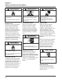
For Your Safety!
These precautions should be followed at all times. Failure to follow these precautions could result in
injury to yourself and others.
WARNING
WARNING
Accidental Starts can cause
severe injury or death.
Rotating Parts can cause severe
injury.
Disconnect and ground spark plug
leads before servicing.
Stay away while engine is in
operation.
Accidental Starts!
Disabling engine. Accidental
starting can cause severe
injury or death. Before working
on the engine or equipment,
disable the engine as follows: 1)
Disconnect the spark plug lead(s).
2) Disconnect negative (-) battery
cable from battery.
Rotating Parts!
Keep hands, feet, hair, and clothing
away from all moving parts to
prevent injury. Never operate the
engine with covers, shrouds, or
guards removed.
WARNING
Hot Parts can cause severe burns.
Do not touch engine while operating
or just after stopping.
Hot Parts!
Engine components can get
extremely hot from operation. To
prevent severe burns, do not touch
these areas while the engine is
running—or immediately after it
is turned off. Never operate the
engine with heat shields or guards
removed.
1.1
Section 1
Safety and General Information
WARNING
WARNING
WARNING
Explosive Fuel can cause fires and
severe burns.
Carbon Monoxide can cause
severe nausea, fainting or death.
Explosive Gas can cause fires and
severe acid burns.
Stop engine before filling fuel tank.
Do not operate engine in closed or
confined area.
Charge battery only in a well
ventilated area. Keep sources of
ignition away.
Explosive Fuel!
Gasoline is extremely flammable
and its vapors can explode if
ignited. Store gasoline only in
approved containers, in well
ventilated, unoccupied buildings,
away from sparks or flames. Do
not fill the fuel tank while the
engine is hot or running, since
spilled fuel could ignite if it comes
in contact with hot parts or sparks
from ignition. Do not start the
engine near spilled fuel. Never use
gasoline as a cleaning agent.
WARNING
Lethal Exhaust Gases!
Engine exhaust gases contain
poisonous carbon monoxide.
Carbon monoxide is odorless,
colorless, and can cause death
if inhaled. Avoid inhaling exhaust
fumes, and never run the engine
in a closed building or confined
area.
WARNING
Uncoiling Spring can cause severe
injury.
Wear safety goggles or face
protection when servicing retractable
starter.
Cleaning Solvents can cause
severe injury or death.
Use only in well ventilated areas away
from ignition sources.
Flammable Solvents!
Carburetor cleaners and solvents
are extremely flammable. Keep
sparks, flames, and other sources
of ignition away from the area.
Follow the cleaner manufacturer’s
warnings and instructions on its
proper and safe use. Never use
gasoline as a cleaning agent.
1.2
Spring Under Tension!
Retractable starters contain a
powerful, recoil spring that is
under tension. Always wear safety
goggles when servicing retractable
starters and carefully follow
instructions in "Retractable Starter"
Section 7 for relieving spring
tension.
Explosive Gas!
Batteries produce explosive
hydrogen gas while being
charged. To prevent a fire or
explosion, charge batteries only in
well ventilated areas. Keep
sparks, open flames, and other
sources of ignition away from the
battery at all times. Keep batteries
out of the reach of children.
Remove all jewelry when servicing
batteries.
Before disconnecting the negative
(-) ground cable, make sure all
switches are OFF. If ON, a spark
will occur at the ground cable
terminal which could cause an
explosion if hydrogen gas or
gasoline vapors are present.
CAUTION
Electrical Shock can cause injury.
Do not touch wires while engine is
running.
Electrical Shock!
Never touch electrical wires or
components while the engine is
running. They can be sources of
electrical shock.
Section 1
Safety and General Information
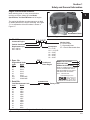
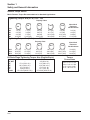
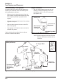
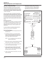
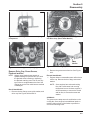
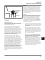
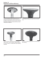
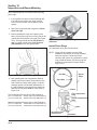
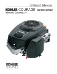
Engine Identification Numbers
When ordering parts, or in any communication
involving an engine, always give the Model,
Specification, and Serial Numbers of the engine.
1
The engine identification numbers appear a on decal
(or decals) affixed to the engine shrouding. See Figure
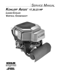
1-1. An explanation of these numbers is shown in
Figure 1-2.
Identification Decal
Figure 1-1. Engine Identification Decal Location.
A. Model No.
Command Engine
Vertical Crankshaft
Displacement (cc)
460 = 460 cc
490 = 490 cc
B. Spec. No.
Engine Model Code
Code
Model
11
CV11
12
CV12.5
22
CV13
14
CV14
41
CV15
43
CV16
265
CV460-465
275
CV490-495
C. Serial No.
C V 12.5 ST
Version Code
S = Electric Start
T = Retractable Start
ST = Electric/Retractable Start
Horsepower
11 = 11 HP
12.5 = 12.5 HP
13 = 13 HP
14 = 14 HP
15 = 15 HP
16 = 16 HP
or
1203
Variation of
Basic Engine
MODEL NO. CV12.5ST
SPEC. NO. 1203
SERIAL NO.2105810334
A
B
C
REFER TO OWNER'S MANUAL FOR
SAFETY, MAINTENANCE SPECS
AND ADJUSTMENTS. FOR SALES
AND SERVICE IN US/CANADA
CALL: 1-800-544-2444.
www.kohlerengines.com
2105810334
KOHLER CO. KOHLER, WI USA
Year Manufactured Code
Factory Code
Code
Model
21
1991
22
1992
23
1993
24
1994
25
1995
26
1996
27
1997
28
1998
29
1999
30
2000
31
2001
32
2002
Figure 1-2. Explanation of Engine Identification Numbers.
1.3
Section 1
Safety and General Information
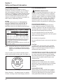
Oil Recommendations
Using the proper type and weight of oil in the
crankcase is extremely important, as is checking oil
daily, and changing oil regularly. Failure to use the
correct oil, or using dirty oil, causes premature engine
wear and failure. Synthetic oil is recommended for
use in LPG-fueled engines because there is less
oxidation or thickening, and deposit accumulation on
intake valves is substantially reduced.
Oil Type
Use high-quality detergent oil of API (American
Petroleum Institute) service class SG, SH, SJ
or higher. Select the viscosity based on the air
temperature at the time of operation as shown below.
**
*
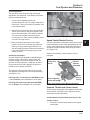
Fuel Recommendations
WARNING: Explosive Fuel!
Gasoline is extremely flammable and its vapors can
explode if ignited. Store gasoline only in approved
containers, in well ventilated, unoccupied buildings,
away from sparks or flames. Do not fill the fuel tank
while the engine is hot or running, since spilled fuel
could ignite if it comes in contact with hot parts or
sparks from ignition. Do not start the engine near
spilled fuel. Never use gasoline as a cleaning agent.
General Recommendations
Purchase gasoline in small quantities and store
in clean, approved containers. A container with a
capacity of 2 gallons or less with a pouring spout is
recommended. Such a container is easier to handle
and helps eliminate spillage during refueling.
Do not use gasoline left over from the previous
season, to minimize gum deposits in your fuel system
and to insure easy starting.
Do not add oil to the gasoline.
*Use of synthetic oil having 5W-20 or 5W-30 rating is
acceptable, up to 4°C (40°F).
**Synthetic oils will provide better starting in extreme cold
below -23°C (-10°F).
NOTE: Using other than service class SG, SH, SJ or
higher oil, or extending oil change intervals
longer than recommended, can cause engine
damage.
A logo or symbol on oil containers identifies the API
service class and SAE viscosity grade. See Figure 1-3.
Do not overfill the fuel tank. Leave room for the fuel to
expand.
Fuel Type
For best results, use only clean, fresh, unleaded
gasoline with a pump sticker octane rating of 87 or
higher. In countries using the Research method, it
should be 90 octane minimum.
Unleaded gasoline is recommended, as it leaves less
combustion chamber deposits. Leaded gasoline may
be used in areas where unleaded is not available
and exhaust emissions are not regulated. Be aware
however, that the cylinder head will require more
frequent service.
Gasoline/Alcohol blends
Gasohol (up to 10% ethyl alcohol, 90% unleaded
gasoline by volume) is approved as a fuel for Kohler
engines. Other gasoline/alcohol blends are not
approved.
Figure 1-3. Oil Container Logo.
Refer to Section 6 - “Lubrication System” for detailed
oil check, oil change, and oil filter change procedures.
1.4
Gasoline/Ether blends
Methyl Tertiary Butyl Ether (MTBE) and unleaded
gasoline blends (up to maximum of 15% MTBE by
volume) are approved as a fuel for Kohler engines.
Other gasoline/ether blends are not approved.
Section 1
Safety and General Information
Periodic Maintenance
1
WARNING: Accidental Starts!
Disabling engine. Accidental starting can cause severe injury or death. Before working on the engine
or equipment, disable the engine as follows: 1) Disconnect the spark plug lead(s). 2) Disconnect negative (-)
battery cable from battery.
Maintenance Schedule
These required maintenance procedures should be performed at the frequency stated in the table. They should
also be included as part of any seasonal tune-up.
Maintenance Required
Frequency
Fill fuel tank.
Check oil level.
Check air cleaner for dirty1, loose, or damaged parts.
Check air intake and cooling areas, clean as necessary1.
Refer to:
Daily or Before
Starting Engine
•
•
•
•
Every 25 Hours
• Service precleaner element1.
Section 5
Section 6
Section 4
Section 4
Section 4
Every
100 Hours
• Replace air cleaner element1.
• Change oil1.
• Remove cooling shrouds and clean cooling areas1.
Section 4
Section 6
Section 4
Every
200 Hours
• Change oil filter1.
• Check spark plug condition and gap.
Section 6
Section 8
Annually or
• Have bendix starter drive serviced2.
Section 8
Every
• Have solenoid shift starter disassembled and cleaned2.
Section 8
500 Hours
1
Perform these maintenance procedures more frequently under extremely dusty, dirty conditions.
2
Have a Kohler Engine Service Dealer perform this service. Not necessary on Delco Starters.
Storage
If the engine will be out of service for two months or
more, use the following storage procedure.
1. Clean the exterior surfaces of the engine.
2. Change the oil and oil filter while the engine is
still warm from operation. See “Change Oil and
Oil Filter” in Section 6.
3. The fuel system must be completely emptied,
or the gasoline must be treated with a stabilizer
to prevent deterioration. If you choose to
use a stabilizer, follow the manufacturers
recommendations, and add the correct amount
for the capacity of the fuel system. Fill the fuel
tank with clean, fresh gasoline. Run the engine
for 2-3 minutes to get stabilized fuel into the
carburetor.
To empty the system, run the engine until the tank
and system are empty.
4. Remove the spark plug. Add one tablespoon of
engine oil into the spark plug hole. Install the
plug, but do not connect the plug lead. Crank the
engine two or three revolutions.
5. Remove the spark plug. Cover the spark plug
hole with your thumb, and turn the engine
over until the piston is at the top of its stroke.
(Pressure against thumb is greatest.) Reinstall
the plug, but do not connect the plug lead.
6. Store the engine in a clean, dry place.
1.5
Section 1
Safety and General Information
Air Filter
and Cover
CL Cylinder
Oil Filter
Carburetor
Fuel Shut-off
Solenoid
Carburetor
Fuel Inlet
47
(1.85)
Engine Mounting
Surface
Oil Drain Plug
3/8 NPT Inch
17
(.67)
262
(10.31)
CL Cylinder
Oil Filter Side
24.0
(9.4)
25.4
(1.00)
Valve Cover End
411
(16.18)
Air Cleaner
Cover Removal
6.34 Keyway Width
(.250)
296
(11.65)
321
(12.64)
CL Cylinder
137.5
(5.41)
Exhaust Flange
Mounting Surface
Engine Mounting
Surface
25.4
(1.00)
Starter Motor
26.5
(1.04)
62.5
(2.46)
6.34
Keyway Width
(.250)
Starter Side
CL Throttle Cable
19
(.74)
207
(80.16)
204
(8.04)
176.6
(6.95)
372
(14.66)
45°
CL Cylinder
124
(4.88)
220.2
(8.67)
45°
60.0
(2.36)
4xM8x1.25
254
(10.0)
CL Cylinder
135.0
(5.31)
Oil Level
Dipstick & Fill
108
(4.25)
328*
(12.91)
4.0
(.16)
463*
(18.23)
Rotation
40°
Flywheel End
*CV11-16 10 mm shorter
M8x1.25
2 Studs
35°
35°
Exhaust Flange
Mounting Surface
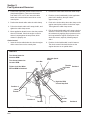
Engine Mounting Surface
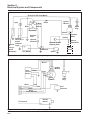
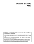
Dimensions in () are inch equivalents.
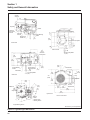
Figure 1-4. Typical Engine Dimensions.
1.6
Section 1
Safety and General Information
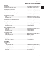
General Specifications¹
Power (@ 3600 RPM, corrected to SAE J1995)
CV11 .................................................................................. 8.2 kW (11 HP)
CV12.5 ............................................................................... 9.33 kW (12.5 HP)
CV13 .................................................................................. 9.75 kW (13 HP)
CV14 .................................................................................. 10.5 kW (14 HP)
CV15 .................................................................................. 11.19 kW (15 HP)
CV16 .................................................................................. 11.9 kW (16 HP)
CV460-465 ......................................................................... 11.9 kW (16 HP)-13.0 kW (16.5 HP)
CV490-495 ......................................................................... 12.7 kW (17 HP)-13.4 kW (18 HP)
1
Max Torque (@ RPM indicated)
CV11 .................................................................................. 27.4 N·m (20.2 ft. lb.) @ 2000
CV12.5 ............................................................................... 27.8 N·m (20.5 ft. lb.) @ 2500
CV13 .................................................................................. 27.8 N·m (20.5 ft. lb.) @ 2500
CV14 .................................................................................. 28.9 N·m (21.3 ft. lb.) @ 2500
CV15 .................................................................................. 33.2 N·m (24.5 ft. lb.) @ 2400
CV16 .................................................................................. 35.3 N·m (26.0 ft. lb.) @ 2400
CV460-465 ......................................................................... 36.3 N·m (26.8 ft. lb.) @ 2400
CV490-495 ......................................................................... 37.8 N·m (27.9 ft. lb.)-38.1 N·m (28.1 ft. lb.) @ 2400
Bore
CV11-14, CV460-465 ......................................................... 87 mm (3.43 in.)
CV15, CV16, CV490-495 ................................................... 90 mm (3.60 in.)
Stroke
CV11-16 ............................................................................. 67 mm (2.64 in.)
CV460-465, CV490-495..................................................... 77 mm (3.03 in.)
Displacement
CV11-14 ............................................................................. 398 cc (24.3 cu. in.3)
CV15, CV16 ....................................................................... 426 cc (26.0 cu. in.3)
CV460-465 ......................................................................... 460 cc (27.9 cu. in.3)
CV490-495 ......................................................................... 490 cc (29.9 cu. in.3)
Compression Ratio ................................................................... 8.5:1
Weight (approx.)
CV11-16 ............................................................................. 39.54 kg (87 lb.)
CV460-465, CV490-495..................................................... 41.9 kg (90 lb.)
Oil Capacity (approx.) ............................................................... 1.9 L (2.0 U.S. qt.)
Air Cleaner
Base Nut Torque ....................................................................... 9.9 N·m (88 in. lb.)
Wing Nut Torque ....................................................................... 1.5 N·m (12 in. lb.)
Angle of Operation - Maximum (at full oil level)
Intermittent - All Directions........................................................ 35°
Continuous - All Directions ....................................................... 20°
1
Values are in Metric units. Values in parentheses are English equivalents. Lubricate threads with engine oil prior
to assembly.
1.7
Section 1
Safety and General Information
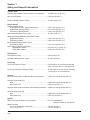
Balance Shaft
End Play ........................................................................................................0.0575/0.3625 mm (0.0027/0.0137 in.)
Running Clearance ........................................................................................0.0250/0.1520 mm (0.0009/0.0059 in.)
Bore I.D.
New .........................................................................................................20.000/20.025 mm (0.7874/0.7884 in.)
Max. Wear Limit ......................................................................................20.038 mm (0.7889 in.)
Balance Shaft Bearing Surface O.D.
New .........................................................................................................19.962/19.975 mm (0.7859/0.7864 in.)
Max. Wear Limit ......................................................................................19.959 mm (0.7858 in.)
Camshaft
End Play (free)...............................................................................................0.088/0.393 mm (0.003/0.015 in.)
End Play (with shims) ....................................................................................0.076/0.127 mm (0.003/0.005 in.)
Running Clearance ........................................................................................0.025/0.105 mm (0.0010/0.0041 in.)
Bore I.D.
New .........................................................................................................20.000/20.025 mm (0.7874/0.7884 in.)
Max. Wear Limit ......................................................................................20.038 mm (0.7889 in.)
Camshaft Bearing Surface O.D.
New ........................................................................................................19.962/19.975 mm (0.7859/0.7864 in.)
Max. Wear Limit .....................................................................................19.959 mm (0.7858 in.)
Carburetor
Preliminary Low Idle Fuel Needle Setting.....................................................1 Turn
Fuel Bowl Retaining Screw Torque...............................................................5.1-6.2 N·m (45-55 in. lb.)
Connecting Rod
Cap Fastener Torque (torque in increments)
6 mm straight shank bolt .........................................................................11.3 N·m (100 in. lb.)
8 mm step-down bolt ...............................................................................14.7 N·m (130 in. lb.)
8 mm straight shank bolt .........................................................................22.7 N·m (200 in. lb.)
Connecting Rod-to-Crankpin Running Clearance at 21°C (70°F)
New .........................................................................................................0.030/0.055 mm (0.0012/0.0022 in.)
Max. Wear Limit ......................................................................................0.07 mm (0.0025 in.)
Connecting Rod-to-Crankpin Side Clearance ...............................................0.18/0.41 mm (0.007/0.016 in.)
Connecting Rod-to-Piston Pin Running Clearance at 21°C (70°F) ...............0.015/0.028 mm (0.0006/0.0011 in.)
Piston Pin End I.D.
New ........................................................................................................19.015/19.023 mm (0.7486/0.7489 in.)
Max. Wear Limit .....................................................................................19.036 mm (0.7495 in.)
Crankcase
Governor Cross Shaft Bore I.D.
New ........................................................................................................6.025/6.050 mm (0.2372/0.2382 in.)
Max. Wear Limit .....................................................................................6.063 mm (0.2387 in.)
1.8
Section 1
Safety and General Information
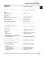
Crankshaft
End Play (free)..........................................................................................0.0575/0.4925 mm (0.0022/0.0193 in.)
End Play (thrust bearing with shims) ........................................................0.050/0.530 mm (0.0020/0.0209 in.)
Crankshaft Bore in Crankcase I.D.
New ....................................................................................................44.965/44.990 mm (1.7702/1.7712 in.)
Max. Wear Limit .................................................................................44.9758/45.0012 mm (1.7707/1.7717 in.)
Crankshaft Bore in Crankcase Running Clearance
New ....................................................................................................0.0300/0.0770 mm (0.0011/0.0030 in.)
Crankshaft Bore in Oil Pan I.D.
New ....................................................................................................41.965/42.003 mm (1.6521/1.6536 in.)
Max. Wear Limit .................................................................................41.9760/42.0141 mm (1.6526/1.6541 in.)
Crankshaft Bore in Oil Pan Running Clearance
New ....................................................................................................0.0300/0.0880 mm (0.0011/0.0034 in.)
Flywheel End Main Bearing Journal
O.D. - New .........................................................................................44.913/44.935 mm (1.7682/1.7691 in.)
O.D. - Max. Wear Limit.......................................................................44.84 mm (1.765 in.)
Max. Taper .........................................................................................0.022 mm (0.0009 in.)
Max. Out-of-Round ............................................................................0.025 mm (0.0010 in.)
Oil Pan End Main Bearing Journal
O.D. - New .........................................................................................41.915/41.935 mm (1.6502/1.6510 in.)
O.D. - Max. Wear Limit.......................................................................41.86 mm (1.648 in.)
Max. Taper .........................................................................................0.020 mm (0.0008 in.)
Max. Out-of-Round ............................................................................0.025 mm (0.0010 in.)
Connecting Rod Journal
O.D. - New .........................................................................................38.958/30.970 mm (1.5338/1.5343 in.)
O.D. - Max. Wear Limit.......................................................................38.94 mm (1.5328 in.)
Max. Taper .........................................................................................0.012 mm (0.0005 in.)
Max. Out-of-Round ............................................................................0.025 mm (0.0010 in.)
Crankshaft T.I.R.
PTO End, Crank in Engine .................................................................0.30 mm (0.012 in.)
Entire Crank, in V-Blocks ...................................................................0.10 mm (0.0039 in.)
Cylinder Bore
Cylinder Bore I.D.
New
CV11-14, CV460-465 .......................................................................87.000/87.025 mm (3.4252/3.4262 in.)
CV15, CV16, CV490-495 .................................................................90.000/90.025 mm (3.5433/3.5443 in.)
Max. Wear Limit
CV11-14, CV460-465 .......................................................................87.063 mm (3.4277 in.)
CV15, CV16, CV490-495 .................................................................90.063 mm (3.5458 in.)
Max. Out-of-Round ............................................................................0.12 mm (0.0047 in.)
Max. Taper .........................................................................................0.05 mm (0.0020 in.)
1.9
1
Section 1
Safety and General Information
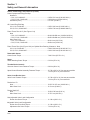
Cylinder Head
Cylinder Head Fastener Torque (torque in 2 increments)......... 24, 48.9 N·m (18, 36 ft. lb.)
Max. Out-of-Flatness ................................................................ 0.076 mm (0.003 in.)
Rocker Pedestal Fastener Torque ............................................ 11.3 N·m (100 in. lb.)
Electric Starter
Starter Thru Bolt Torque
UTE/Johnson Electric, Eaton (Inertia Drive) ...................... 4.5-5.7 N·m (40-50 in. lb.)
Nippendenso (Solenoid Shift) ............................................ 4.5-7.5 N·m (40-84 in. lb.)
Delco-Remy (Solenoid Shift) .............................................. 5.6-9.0 N·m (49-79 in. lb.)
Starter Mounting Screw Torque (All)......................................... 15.3 N·m (135 in. lb.)
Solenoid Mounting Hardware (Nut/Screw) Torque
Nippendenso Starter .......................................................... 6.0-9.0 N·m (53-79 in. lb.)
Delco-Remy Starter ........................................................... 4.0-6.0 N·m (35-53 in. lb.)
Brush Holder Mounting Screw Torque
Delco-Remy Starter ........................................................... 2.5-3.3 N·m (22-29 in. lb.)
Nut, Positive (+) Brush Lead Torque
Nippendenso Starter.................................................... 8.0-12.0 N·m (71-106 in. lb.)
Delco-Remy Starter ..................................................... 6.0-9.0 N·m (53-79 in. lb.)
Fan/Flywheel
Fan Fastener Torque ................................................................ 9.9 N·m (88 in. lb.)
Flywheel Retaining Screw Torque ............................................ 66.4 N·m (49 ft. lb.)
Fuel Pump
Fuel Pump Fastener Torque ..................................................... 9.0 N·m (80 in. lb.) Into new as-cast hole
4.2-5.1 N·m (37-45 in. lb.) Into used hole
Fuel Pump Pad Cover Fastener Torque ................................... 10.7 N·m (95 in. lb.) Into new as-cast hole
7.3 N·m (65 in. lb.) Into used hole
Governor
Governor Cross Shaft to Crankcase Running Clearance ......... 0.025/0.075 mm (0.0010/0.0030 in.)
Governor Cross Shaft O.D.
New .................................................................................... 5.975/6.000 mm (0.2352/0.2362 in.)
Max. Wear Limit ................................................................. 5.962 mm (0.2347 in.)
Governor Gear Shaft-to-Governor Gear Running Clearance ... 0.050/0.160 mm (0.0019/0.0063 in.)
Governor Gear Shaft O.D.
New .................................................................................... 5.990/6.000 mm (0.2358/0.2362 in.)
Max. Wear Limit ................................................................. 5.977 mm (0.2353 in.)
Ignition
Spark Plug Type (Champion® or equivalent) ............................. RC12YC (Standard) or
Premium Gold 2071 (Pro Series)
Spark Plug Gap
CV11-15, CV460-465, CV490-495 ..................................... 1.02 mm (0.040 in.)
CV11-14 LP, CV16 ............................................................. 0.76 mm (0.030 in.)
1.10
Section 1
Safety and General Information
Ignition (Cont'd)
Spark Plug Torque .................................................................... 24.4-29.8 N·m (18-22 ft. lb.)
1
Ignition Module Air Gap ............................................................ 0.200/0.300 mm (0.0078/0.0118 in.)
Ignition Module Fastener Torque .............................................. 6.2 N·m (55 in. lb.) Into new as-cast hole
4.0 N·m (35 in. lb.) Into used hole
Muffler
Muffler Retaining Nuts .............................................................. 24.4 N·m (216 in. lb.)
Oil Filter/Oil Pan
Oil Filter Torque ........................................................................ 10.4-12.7 N·m (90-110 in. lb.)
Oil Filter Drain Plug (1/8" NPT) Torque..................................... 7.3-9.0 N·m (65-80 in. lb.)
Oil Pan Fastener Torque........................................................... 24.4 N·m (216 in. lb.)
Oil Sentry™ Pressure Switch Torque ......................................... 6.8 N·m (60 in. lb.)
Oil Pump Cover Fastener Torque ............................................. 6.2 N·m (55 in. lb.) Into new as-cast hole
4.0 N·m (35 in. lb.) Into used hole
Piston, Piston Rings, and Piston Pin
Piston-to-Piston Pin (selective fit) ............................................. 0.006/0.017 mm (0.0002/0.0007 in.)
Piston Pin Bore I.D.
New .................................................................................... 19.006/19.012 mm (0.7483/0.7485 in.)
Max. Wear Limit ................................................................. 19.025 mm (0.7490 in.)
Piston Pin O.D.
New .................................................................................... 18.995/19.000 mm (0.7478/0.7480 in.)
Max. Wear Limit ................................................................. 18.994 mm (0.74779 in.)
Top Compression Ring-to-Groove Side Clearance
CV11-14, CV460-465 ......................................................... 0.034/0.100 mm (0.0013/0.0039 in.)
CV15, CV16, CV490-495 ................................................... 0.060/0.105 mm (0.0023/0.0041 in.)
Middle Compression Ring-to-Groove Side Clearance
CV11-14, CV460-465 ......................................................... 0.040/0.080 mm (0.0016/0.0032 in.)
CV15, CV16, CV490-495 ................................................... 0.040/0.085 mm (0.0015/0.0033 in.)
Oil Control Ring-to-Groove Side Clearance
CV11-14, CV460-465 ......................................................... 0.036/0.186 mm (0.0014/0.0073 in.)
CV15, CV16, CV490-495 ................................................... 0.036/0.186 mm (0.0014/0.0073 in.)
Top Compression Ring End Gap
New Bore
CV11-14, CV460-465 ....................................................... 0.250/0.500 mm (0.010/0.020 in.)
CV15, CV16, CV490-495 ................................................. 0.28/0.51 mm (0.011/0.020 in.)
Used Bore (max.) ............................................................... 0.79 mm (0.031 in.)
1.11
Section 1
Safety and General Information
Piston, Piston Rings, and Piston Pin (Cont'd.)
Center Compression Ring End Gap
New Bore
CV11-14, CV460-465 ....................................................... 0.250/0.510 mm (0.0010/0.020 in.)
CV15, CV16, CV490-495 ................................................. 0.22/0.48 mm (0.008/0.018 in.)
Used Bore (max.) ............................................................... 0.76 mm (0.030 in.)
Oil Control Ring End Gap
CV11-14, CV460-465 ......................................................... 0.250/1.020 mm (0.010/0.040 in.)
CV15, CV16, CV490-495 ................................................... 0.250/0.760 mm (0.0098/0.0299 in.)
Piston Thrust Face O.D. (See Figure 10-4)
New
CV11-14, CV460-465 ....................................................... 86.941/86.959 mm (3.4229/3.4236 in.)
CV15, CV16, CV490-495 ................................................. 89.951/89.969 mm (3.5413/3.5420 in.)
Max. Wear Limit
CV11-14, CV460-465 ....................................................... 86.814 mm (3.4179 in.)
CV15, CV16, CV490-495 ................................................. 89.824 mm (3.5363 in.)
Piston Thrust Face (See Figure 10-4)-to-Cylinder Bore Running Clearance - New
CV11-14, CV460-465 ......................................................... 0.041/0.044 mm (0.0016/0.0017 in.)
CV15, CV16, CV490-495 .................................................. 0.031/0.043 mm (0.0012/0.0016 in.)
Retractable Starter
Center Screw Torque ................................................................ 7.4-8.5 N·m (65-75 in. lb.)
Stator
Stator Mounting Screw Torque ................................................. 6.2 N·m (55 in. lb.)
Throttle/Choke Controls
Governor Control Lever Fastener Torque ................................. 9.9 N·m (88 in. lb.)
Speed Control Bracket Assembly Fastener Torque .................. 10.7 N·m (95 in. lb.) Into new as-cast hole
7.3 N·m (65 in. lb.) Into used hole
Valve Cover/Rocker Arms
Valve Cover Fastener Torque ................................................... 10.7 N·m (95 in. lb.) Into new as-cast hole
7.3 N·m (65 in. lb.) Into used hole
Rocker Arm I.D.
New .................................................................................... 15.837/16.127 mm (0.63/0.64 in.)
Max. Wear Limit ................................................................. 16.13 mm (0.640 in.)
Rocker Shaft O.D.
New .................................................................................... 15.90/15.85 mm (0.63 in.)
Max. Wear Limit ................................................................. 15.727 mm (0.619 in.)
Non-Adjustable Valve Lash Configuration
Rocker Arm Screw Torque ................................................. 11.3 N·m (100 in. lb.)
Adjustable Valve Lash Configuration
Rocker Arm Pivot Stud Torque ........................................... 11.3 N·m (100 in. lb.)
Adjustment Set Screw Torque ............................................ 7.3 N·m (65 in. lb.)
1.12
Section 1
Safety and General Information
Valves and Valve Lifters
Hydraulic Valve Lifter to Crankcase Running Clearance .......... 0.0124/0.0501 mm (0.0005/0.0020 in.)
1
Intake Valve Stem-to-Valve Guide Running Clearance ............ 0.038/0.076 mm (0.0015/0.0030 in.)
Exhaust Valve Stem-to-Valve Guide Running Clearance ......... 0.050/0.088 mm (0.0020/0.0035 in.)
Intake Valve Guide I.D.
New .................................................................................... 7.038/7.058 mm (0.2771/0.2779 in.)
Max. Wear Limit ................................................................. 7.134 mm (0.2809 in.)
Exhaust Valve Guide I.D.
New .................................................................................... 7.038/7.058 mm (0.2771/0.2779 in.)
Max. Wear Limit ................................................................. 7.159 mm (0.2819 in.)
Valve Guide Reamer Size
STD .................................................................................... 7.048 mm (0.2775 in.)
0.25 mm O.S. ..................................................................... 7.298 mm (0.2873 in.)
Intake Valve Minimum Lift......................................................... 8.96 mm (0.353 in.)
Exhaust Valve Minimum Lift ..................................................... 9.14 mm (0.360 in.)
Nominal Valve Seat Angle ........................................................ 45°
1.13
Section 1
Safety and General Information
General Torque Values
Metric Fastener Torque Recommendations for Standard Applications
Tightening Torque: N·m (in. lb.) + or - 10%
Property Class
Size
M4
M5
M6
M8
4.8
5.8
8.8
10.9
12.9
Noncritical
Fasteners
Into Aluminum
1.2 (11)
2.5 (22)
4.3 (38)
10.5 (93)
1.7 (15)
3.2 (28)
5.7 (50)
13.6 (120)
2.9 (26)
5.8 (51)
9.9 (88)
24.4 (216)
4.1 (36)
8.1 (72)
14.0 (124)
33.9 (300)
5.0 (44)
9.7 (86)
16.5 (146)
40.7 (360)
2.0 (18)
4.0 (35)
6.8 (60)
17.0 (150)
Tightening Torque: N·m (ft. lb.) + or - 10%
Property Class
4.8
M10
M12
M14
21.7 (16)
36.6 (27)
58.3 (43)
5.8
27.1 (20)
47.5 (35)
76.4 (55)
8.8
47.5 (35)
82.7 (61)
131.5 (97)
10.9
12.9
66.4 (49)
116.6 (86)
184.4 (136)
81.4 (60)
139.7 (103)
219.7 (162)
Oil Drain Plugs Tightening Torque: N•m (English Equiv.)
Size
1/8" NPT
1/4"
3/8"
1/2"
3/4"
X-708-1
1.14
Into Cast Iron
–
17.0 (150 in. lb.)
20.3 (180 in. lb.)
27.1 (20 ft. lb.)
33.9 (25 ft. lb.)
27.1/33.9 (20/25 ft. lb.)
Noncritical
Fasteners
Into Aluminum
Into Aluminum
4.5 (40 in. lb.)
11.3 (100 in. lb.)
13.6 (120 in. lb.)
17.6 (13 ft. lb.)
21.7 (16 ft. lb.)
27.1/33.9 (20/25 ft. lb.)
33.9 (25)
61.0 (45)
94.9 (70)
Torque
Conversions
N·m = in. lb. x 0.113
N·m = ft. lb. x 1.356
in. lb. = N·m x 8.85
ft. lb. = N·m x 0.737
CV11-16
Section
2
CV460-465,
CV490-495
Special
Tools
Section 2
Special Tools
Kohler Special Service Tools
Kohler Co. has made an agreement with the Service
Tools Div. of SPX Corp. (a subsidiary of Owatonna
Tool Corp.) to handle our special service tools. The
intent of this program is to provide you with a single
source for all Kohler special tools, and to make it easy
and convenient to obtain those tools, at reasonable
cost. Tool orders can be placed with SPX by any of
three methods. Mail orders should be sent to:
OTC/SPX Corp., 655 Eisenhower Dr., Owatonna, MN
55060. You can also fax the order to (800) 578-7375
(USA and Canada) or (507) 455-7063 (International).
Finally, you can order by phone at (800) 533-0492
(USA and Canada) or (507) 455-7223 (International).
Repair Tools
These quality tools are designed to help you perform
specific disassembly, repair, and reassembly
procedures. By using tools designed for the job,
you can service engines easier, faster, and safer! In
addition, you’ll increase your service capabilities and
customer satisfaction by decreasing engine down
time.
2
COMMAND Tool Kit No. KO3213–This kit is
designed for the current Kohler Engine Service Dealer
already having the KO3211A basic tool kit. This kit
includes all additional tools necessary to service
current Command series engines.
COMMAND Tool Kit No. KO3214–This kit is for the
new Kohler Dealer servicing the Command series
engines only.
RTV Silicone Sealant
RTV silicone sealant is used as a gasket between the
crankcase and closure plate, and between the valve
cover and head. The recommended sealant is Loctite®
5900, available under Kohler Part No. 25 597 07-S.
Prepare the sealing surfaces of the crankcase and
closure plate as directed by the sealant manufacturer
or refer to Service Bulletin 252.
Tool Kit No. KO3211A–This basic tool kit includes
tools necessary to service Kohler K-Series and
Magnum engines.
2.1
Section 2
Special Tools
Diagnostic and Repair Tools
The tools listed in the following table are used for specific diagnosis or repair procedures, as described. Order
from SPX Corp.
Description
SPX Part No.
Hydraulic Lifter Tool
Designed to remove and install hydraulic lifters
KO1044
Ignition Tester
Used for testing output on capacitive discharge (CD) ignition systems
KO1046
Ignition Tester
Used for testing ouput on all other systems, except CD
KO1047
Water Manometer
Used for testing crankcase vacuum and exhaust back pressure
KO1048
Inductive Tachometer
Used for checking the operating speed (RPM) of an engine
KO3216
Ammeter Set
Used for checking current flow in charging and cranking circuits
KO3218
Cylinder Leakdown Tester
Used for checking combustion retention and if cylinder, piston, rings, or valves are worn
KO3219
Oil Pressure Test Kit
Used to test/verify oil pressure on pressure lubricated engines
KO3220
Electric Starter Service Kit
Used to service all electric starters, including solenoid shift
KO3226
Electric Starter Service Kit
Used to remove and reinstall drive retainers on most inertia drive starters
KO1049
Rectifier-Regulator Tester
Used for testing rectifier-regulators
KO3221
Spark Advance Module Tester
Used to test the SAM on engines with Smart Spark
KO3222
Vacuum/Pressure Tester
Used like the water manometer but easier to operate, transport, and maintain
KO3223
Spanner Wrench
Used for installing push rods or rotating crankshaft
OEM6200
Engine Analysis Kit
Used for testing running conditions of Kohler engines in applications
KO1000A
2.2
Section 2
Special Tools
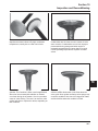
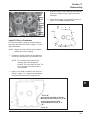
Special Tools You Can Make
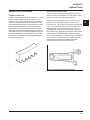
Flywheel Holding Tool
Flywheel removal and reinstallation becomes a “snap”
using a handy holding tool you can make out of a
piece of an old “junk” flywheel ring gear as shown in
Figure 2-1. Using an abrasive cut-off wheel, cut out
a six tooth segment of the ring gear as shown. Grind
off any burrs or sharp edges. The segment can be
used in place of a strap wrench. Invert the segment
and place it between the ignition module bosses on
the crankcase, so the tool teeth engage the ring gear
teeth on the flywheel. The bosses will “lock” the tool
and flywheel in position for loosening, tightening or
removing with a puller.
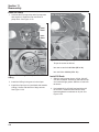
Rocker Arm/Crankshaft Tool
If you don’t have a spanner wrench to lift the rocker
arms or to turn the crankshaft, you can make a tool for
doing this out of an old junk connecting rod.
Find a used connecting rod from a 10 HP or larger
engine. Remove and discard the rod cap. If it is a
Posi-Lock rod, you will also need to remove the studs.
If it is a Command rod, you will need to grind off the
aligning steps, so the joint surface is flat. Find a 1"
long capscrew with the correct thread size to match
the threads in the connecting rod. Obtain a flat washer
with the correct I.D. to slip on the capscrew and an
O.D. of approximately 1". Kohler Part No. 12 468 05-S
can be used if you don’t have the right size on hand.
Assemble the capscrew and washer to the joint
surface of the rod, as shown in Figure 2-2.
Figure 2-1. Flywheel Holding Tool.
Figure 2-2. Rocker Arm/Crankshaft Tool.
2.3
2
Section 2
Special Tools
2.4
CV11-16
Section
3
CV460-465,
CV490-495
Troubleshooting
Section 3
Troubleshooting
3
Troubleshooting Guide
When troubles occur, be sure to check the simple
causes which, at first, may seem too obvious to be
considered. For example, a starting problem could be
caused by an empty fuel tank.
Some common causes of engine troubles are listed
below. Use these to locate the causing factors.
Engine Cranks But Will Not Start
1. Empty fuel tank.
2. Fuel shut-off valve closed.
3. Dirt or water in the fuel system.
4. Clogged fuel line.
5. Spark plug lead disconnected.
6. Key switch or kill switch in ‘‘off’’ position.
7. Faulty spark plug.
8. Faulty ignition module.
Engine Starts But Does Not Keep Running
1. Restricted fuel tank cap vent.
2. Dirt or water in the fuel system.
3. Faulty choke or throttle controls.
4. Loose wires or connections that short the kill
terminal of ignition module to ground.
5. Faulty carburetor.
6. Faulty cylinder head gasket.
Engine Starts Hard
1. PTO drive is engaged.
2. Dirt or water in the fuel system.
3. Clogged fuel line.
4. Loose or faulty wires or connections.
5. Faulty choke or throttle controls.
6. Faulty spark plug.
7. Low compression.
8. Faulty ACR mechanism.
Engine Will Not Crank
1. PTO drive is engaged.
2. Battery (if equipped) is discharged.
3. Safety interlock switch is engaged.
4. Loose or faulty wires or connections.
5. Faulty key switch or ignition switch.
6. Faulty electric starter (if equipped).
7. Retractable starter not engaging in drive cup.
8. Seized internal engine components.
Engine Runs But Misses
1. Dirt or water in the fuel system.
2. Spark plug lead disconnected.
3. Loose wires or connections that intermittently
short the kill terminal of ignition module to ground.
4. Engine overheated.
5. Faulty ignition module.
Engine Will Not Idle
1. Restricted fuel tank cap vent.
2. Dirt or water in the fuel system.
3. Faulty spark plug.
4. Idle fuel adjusting needle improperly set.
5. Idle speed adjusting screw improperly set.
6. Low compression.
7. Stale fuel and/or gum in carburetor.
Engine Overheats
1. Air intake/grass screen, cooling fins, or cooling
shrouds clogged.
2. Excessive engine load.
3. Low crankcase oil level.
4. High crankcase oil level.
5. Faulty carburetor.
Engine Knocks
1. Excessive engine load.
2. Low crankcase oil level.
3. Old/improper fuel.
4. Internal wear or damage.
3.1
Section 3
Troubleshooting
Engine Loses Power
1. Low crankcase oil level.
2. High crankcase oil level.
3. Dirty air cleaner element.
4. Dirt or water in the fuel system.
5. Excessive engine load.
6. Engine overheated.
7. Faulty spark plug.
8. Low compression.
9. Exhaust restriction.
Engine Uses Excessive Amount Of Oil
1. Incorrect oil viscosity/type.
2. Clogged or improperly-assembled breather.
3. Crankcase being overfilled.
4. Worn or broken piston rings.
5. Worn cylinder bore.
6. Worn valve stems/valve guides.
External Engine Inspection
Before cleaning or disassembling the engine, make
a thorough inspection of its external appearance and
condition. This inspection can give clues to what might
be found inside the engine (and the cause) when it is
disassembled.
•
Check for buildup of dirt and debris on the
crankcase, cooling fins, grass screen and other
external surfaces. Dirt or debris on these areas
are causes of overheating.
•
Check for obvious oil leaks, and damaged
components. Excessive oil leakage can indicate
a clogged or improperly-assembled breather,
worn or damaged seals and gaskets, or loose or
improperly-torqued fasteners.
•
Check the air cleaner cover and base for damage
or indications of improper fit and seal.
•
Check the air cleaner element. Look for holes,
tears, cracked or damaged sealing surfaces, or
other damage that could allow unfiltered air into
the engine. Also note if the element is dirty or
clogged. These could indicate that the engine has
been underserviced.
3.2
•
Check the carburetor throat for dirt. Dirt in the
throat is further indication that the air cleaner is
not functioning properly.
•
Check the oil level. Note if the oil level is within
the operating range on the dipstick, or if it is low
or overfilled.
•
Check the condition of the oil. Drain the oil into
a container - the oil should flow freely. Check for
metal chips and other foreign particles.
Sludge is a natural by-product of combustion; a small
accumulation is normal. Excessive sludge deposits
could indicate the oil has not been changed at the
recommended intervals, incorrect type or weight of oil
was used, overrich carburetion, or weak ignition, to
name a few.
NOTE: It is good practice to drain oil at a location
away from the workbench. Be sure to allow
ample time for complete drainage.
Cleaning the Engine
After inspecting the external condition of the engine,
clean the engine thoroughly before disassembling it.
Also clean individual components as the engine is
disassembled. Only clean parts can be accurately
inspected and gauged for wear or damage. There
are many commercially available cleaners that will
quickly remove grease, oil, and grime from engine
parts. When such a cleaner is used, follow the
manufacturer’s instructions and safety precautions
carefully.
Make sure all traces of the cleaner are removed
before the engine is reassembled and placed into
operation. Even small amounts of these cleaners can
quickly break down the lubricating properties of engine
oil.
Section 3
Troubleshooting
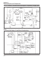
Basic Engine Tests
2. Start the engine and run at no-load, high idle
speed (3200 to 3750 RPM).
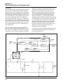
Crankcase Vacuum Test
A partial vacuum should be present in the crankcase
when the engine is operating at normal temperatures.
Pressure in the crankcase (normally caused by a
clogged or improperly-assembled breather) can cause
oil to be forced out at oil seals, gaskets, or other
available spots.
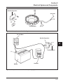
Crankcase vacuum is best measured with a water
manometer or vacuum/pressure test gauge. See
Section 2. Complete instructions are provided with the
testers.
Test the crankcase vacuum with the manometer as
follows:
1. Insert the rubber stopper into the oil fill hole.
Be sure the pinch clamp is installed on the
hose and use the tapered adapters to connect
the hose between the stopper and one of the
manometer tubes. Leave the other tube open to
the atmosphere. Check that the water level in the
manometer is at the "0" line. Make sure the pinch
clamp is closed.
3. Open the clamp and note the water level in the
tube.
The level in the engine side should be a minimum
of 10.2 cm (4 in.) above the level in the open side.
If the level in the engine side is the same as the
open side (no vacuum), or the level in the engine
side is lower than the level in the open side
(pressure), check for the conditions in the table
below.
4. Close the shut-off clamp before stopping the
engine.
To perform the test with the vacuum/pressure
gauge, insert the stopper as in step 1. Insert the
barbed gauge fitting into the hole in the stopper.
Be sure the gauge needle is at "0". Run the
engine, as in step 2, and observe the gauge
reading. Needle movement to the left of "0" is a
vacuum, and movement to the right indicates a
pressure.
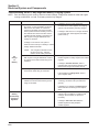
Incorrect Vacuum in Crankcase
Possible Cause
Solution
1. Crankcase breather clogged or inoperative.
1. Disassemble breather, clean parts thoroughly,
reassemble, and recheck pressure.
2. Seals and/or gaskets leaking. Loose or
improperly torqued fasteners.
2. Replace all worn or damaged seals and
gaskets. Make sure all fasteners are tightened
securely. Use appropriate torque values and
sequences when necessary.
3. Piston blowby or leaky valves. Confirm with
cylinder leakdown test.
3. Recondition piston, rings, cylinder bore, valves,
and valve guides.
4. Restricted exhaust.
4. Repair/replace restricted muffler/exhaust
system.
3.3
3
Section 3
Troubleshooting
Compression Test
These engines are equipped with an automatic
compression release (ACR) mechanism. Because
of the ACR mechanism, it is difficult to obtain an
accurate compression reading. As an alternate, use
the leakdown test described below.
Cylinder Leakdown Test
A cylinder leakdown test can be a valuable alternative
to a compression test. By pressurizing the combustion
chamber from an external air source you can
determine if the valves or rings are leaking, and how
badly.
The tester listed on page 2.2 is a relatively simple,
inexpensive leakdown tester for small engines. The
tester includes a quick disconnect for attaching the
adapter hose and a holding tool.
Leakdown Test Instructions
1. Run engine for 3-5 minutes to warm it up.
2. Remove spark plug(s) and air filter from the
engine.
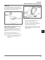
3. Rotate the crankshaft until the piston is at top
dead center (TDC) of the compression stroke.
You will need to hold the engine in this position
while testing. The holding tool supplied with
the tester can be used if the PTO end of the
crankshaft is accessible. Slide the holding tool
onto the crankshaft, align the slot/hole with one
of mounting hold on the PTO face, and tighten
it onto the crankshaft. Install a 3/8" breaker bar
into the slot or square hole of the holding tool,
so it is perpendicular to both the holding tool and
crankshaft PTO, or insert a shoulder bolt through
the slot and thread it into the mounting hole. If the
flywheel end is more accessible, you can use a
breaker bar and socket on the flywheel nut/screw
to hold it in position. You may need an assistant
to hold the breaker bar during testing. If the
engine is mounted in a piece of equipment, you
may be able to hold it by clamping or wedging a
driven component. Just be certain that the engine
cannot rotate off of TDC in either direction.
4. Install the adapter into the spark plug hole, but do
not attach it to the tester at this time.
5. Connect an adequate air source to the tester.
6. Turn the regulator knob in the increase
(clockwise) direction until the gauge needle is in
the yellow ‘‘set’’ area at the low end of the scale.
7. Connect tester quick-disconnect to the adapter.
Note the gauge reading and listen for escaping
air at the carburetor intake, exhaust outlet, and
crankcase breather.
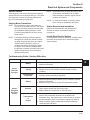
8. Check your test results against the table below:
Leakdown Test Results
Air escaping from crankcase breather ........................................... Defective rings or worn cylinder walls.
Air escaping from exhaust system................................................. Defective exhaust valve.
Air escaping from carburetor ......................................................... Defective intake valve.
Gauge reading in ‘‘low’’ (green) zone ............................................ Piston rings and cylinder in good condition.
Gauge reading in ‘‘moderate’’ (yellow) zone.................................. Engine is still usable, but there is some wear
present. Customer should start planning for
overhaul or replacement.
Gauge reading in ‘‘high’’ (red) zone ............................................... Rings and/or cylinder have considerable wear.
Engine should be reconditioned or replaced.
3.4
CV11-16
Section
4
CV490-495
Air CleanerCV460-465,
and Air Intake
System
Section 4
Air Cleaner and Air Intake System
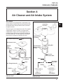
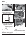
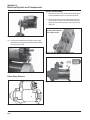
Air Cleaner
Air Duct
These engines are equipped with a replaceable, high
density paper air cleaner element and most also have
the optional oiled, foam precleaner which surrounds
the paper element.
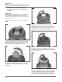
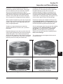
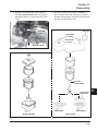
Two basic types of air cleaners are used. The original
configuration is shown in Figure 4-1 and the later
configuration in Figure 4-2. On the original style, air
is drawn through a duct from the blower housing and
from the outside slot. The later type uses a flat base
plate with the enclosure provided by the cover.
Air Cleaner Cover Knob
4
Knob (Part
of Cover)
Air Cleaner
Cover
Optional Foam
Precleaner
Air Cleaner Cover
Optional
Foam
Precleaner
Paper Element
(Extra Capacity
Shown)
Wing nut
Wing Nut
Inner Air
Cleaner Seal
Covered Air
Cleaner Element
Rubber Seal
(Sleeve)
Stud
Air Cleaner
Base Seal
Stud
Hex. Flange Screw (2)
Gasket
Gasket
Bushing
Base
Figure 4-1. Original Air Cleaner Assembly Exploded View.
Open Base
Closed Base
Figure 4-2. Later Style Air Cleaner Assemblies Exploded View.
4.1
Section 4
Air Cleaner and Air Intake System
On these, air is drawn in around the bottom of the
cover, or from the blower housing, rather than from
slots. The flat base allows debris to be brushed away
before the paper element is removed. All types can
use either the standard size element or a higher, extra
capacity paper element.
The original type uses a separate cover retaining
knob which has to be turned completely off to remove
the cover. With the later style, the knob snaps into
the cover and is turned counterclockwise until it
disengages the stud. Other differences are pointed out
in the exploded views.
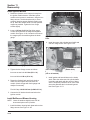
Service
Check the air cleaner daily or before starting the
engine. Check for and correct any buildup of dirt and
debris, and loose or damaged components.
NOTE: Operating the engine with loose or damaged
air cleaner components could allow unfiltered
air into the engine, causing premature wear
and failure.
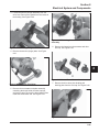
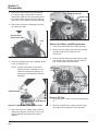
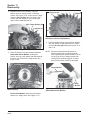
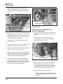
Precleaner Service
If so equipped, wash and reoil the precleaner every 25
hours of operation (more often under extremely dusty
or dirty conditions).
1. Remove the precleaner from the paper element.
2. Wash the precleaner in warm water with
detergent. Rinse the precleaner thoroughly until
all traces of detergent are eliminated. Squeeze
out excess water (do not wring). Allow the
precleaner to air dry.
3. Gently tap the flat side of the paper element to
dislodge dirt. Do not wash the paper element
or use pressurized air, as this will damage the
element. Replace a dirty, bent, or damaged
element with a genuine Kohler element. Handle
new elements carefully; do not use if the sealing
surfaces are bent or damaged.
4. Inspect the rubber seal (sleeve) on the stud. If it
is worn, damaged, or questionable, replace it. A
new seal comes packed with each replacement
element.
5. Reinstall the precleaner, paper element, wing
nut, and air cleaner cover. Make sure the knob is
tightened securely.
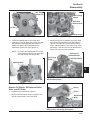
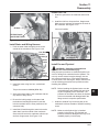
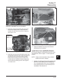
Inspect Air Cleaner Components
Whenever the air cleaner cover is removed, or the
paper element or precleaner are serviced, check the
following areas/components:
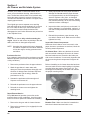
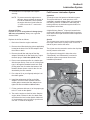
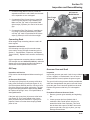
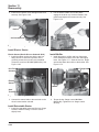
Air Cleaner Base - Make sure the base is secured
and not cracked or damaged. Since the air cleaner
base and carburetor are secured to the intake port
with common hardware, it is extremely important that
the nuts securing these components are tight at all
times.
Before reinstalling an air cleaner base that has been
removed, make sure the metal bushings in the base
mounting holes are present. See Figure 4-3. The
bushings prevent damage to the base and maintain
the proper mounting torque.
3. Saturate the precleaner with new engine oil.
Squeeze out all excess oil.
4. Reinstall the precleaner over the paper element.
5. Reinstall air cleaner cover and tighten the
retaining knob.
Paper Element Service
Every 100 hours of operation (more often under
extremely dusty or dirty conditions), check the paper
element. Clean or replace the element as necessary.
1. Remove the wing nut and air cleaner element.
2. Remove the precleaner (if so equipped) from the
paper element.
4.2
Bushings
Figure 4-3. Bushings in Air Cleaner Base.
Breather Tube - Make sure the tube is attached to
both the air cleaner base and valve cover.
Section 4
Air Cleaner and Air Intake System
NOTE: Damaged, worn, or loose air cleaner
components can allow unfiltered air into the
engine causing premature wear and failure.
Tighten or replace all loose or damaged
components.
Disassembly
The following procedure is for complete disassembly
of all air cleaner components.
1. Loosen the air cleaner cover retaining knob and
remove the air cleaner cover.
2. Remove the wing nut and air cleaner element.
3. If so equipped, remove the precleaner from the
paper element.
4. Disconnect the breather hose from the air cleaner
base.
5. Remove the air cleaner base mounting nuts, air
cleaner base, and gasket.
6. If necessary, remove the self-tapping screws and
stud from the air cleaner base.
Reassembly
The following procedure is for complete assembly of
all air cleaner components.
1. Install the stud and self-tapping screws to the air
cleaner base.
2. Install the gasket, air cleaner base, and base
mounting nuts. Torque the nuts to 9.9 N·m
(88 in. lb.).
Air Intake/Cooling System
Clean Air Intake/Cooling Areas
To ensure proper cooling, make sure the grass screen,
cooling fins, and other external surfaces of the engine
are kept clean at all times.
Every 100 hours of operation (more often under
extremely dusty, dirty conditions), remove the blower
housing and other cooling shrouds. Clean the cooling
fins and external surfaces as necessary. Make sure
the cooling shrouds are reinstalled.
NOTE: Operating the engine with a blocked grass
screen, dirty or plugged cooling fins, and/or
cooling shrouds removed, will cause engine
damage due to overheating.
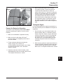
Air Intake Filter (Optional)
Some engines used under extremely dusty conditions
such as floor buffer applications are equipped with a
foam air filter which fits over the retractable starter.
The filter is held in place by velcro studs affixed to the
starter cover. This filter must be checked daily before
each start and frequently during operation. It should
be serviced whenever wax, dust, or dirt builds up on
its surface. If it becomes clogged, the engine can not
receive sufficient cooling air and will overheat.
To service, peel the filter loose from the velstuds, lift
the filter and carefully work the recoil starter handle
through the hole in filter. Clean the filter in soap and
warm water, rinse, squeeze out excess water and
allow it to air dry. If time will not permit air drying, keep
a spare filter on hand (Kohler Part No. 12 050 02-S).
When reinstalling, make sure the foam filter seals
against the blower housing around its base and is
securely attached to the velstuds.
3. Connect the breather hose to the air cleaner base
and valve cover. Secure with hose clamps.
4. If so equipped, install the precleaner (washed
and oiled) over the paper element.
5. Install the air cleaner element and wing nut.
Thread the wing nut on the stud until it contacts
the metal cap on the element, then tighten an
additional 1/2-1 turn.
6. Install the air cleaner cover. Tighten the knob
securely.
4.3
4
Section 4
Air Cleaner and Air Intake System
4.4
CV11-16
Section
5
FuelCV460-465,
System andCV490-495
Governor
Section 5
Fuel System and Governor
Gasoline fuel systems are covered in the first part of
this section. LPG (liquefied propane gas) systems and
the Kohler Emission Sentry™ LPG system are covered
starting on page 5.11. The governor systems start on
page 5.14.
Fuel Recommendations (Gasoline)
WARNING: Explosive Fuel!
Gasoline is extremely flammable and its vapors can
explode if ignited. Store gasoline only in approved
containers, in well ventilated, unoccupied buildings,
away from sparks or flames. Do not fill the fuel tank
while the engine is hot or running, since spilled fuel
could ignite if it comes in contact with hot parts or
sparks from ignition. Do not start the engine near
spilled fuel. Never use gasoline as a cleaning agent.
General Recommendations (Gasoline)
Purchase gasoline in small quantities and store
in clean, approved containers. A container with a
capacity of 2 gallons or less with a pouring spout is
recommended. Such a container is easier to handle
and helps eliminate spillage during refueling.
Do not use gasoline left over from the previous
season, to minimize gum deposits in your fuel system
and to insure easy starting.
Do not add oil to the gasoline.
Do not overfill the fuel tank. Leave room for the fuel to
expand.
Fuel Type (Gasoline)
For best results, use only clean, fresh, unleaded
gasoline with a pump sticker octane rating of 87 or
higher. In countries using the Research method, it
should be 90 octane minimum.
Unleaded gasoline is recommended, as it leaves less
combustion chamber deposits. Leaded gasoline may
be used in areas where unleaded is not available
and exhaust emissions are not regulated. Be aware
however, that the cylinder head will require more
frequent service.
Gasoline/Alcohol blends
Gasohol (up to 10% ethyl alcohol, 90% unleaded
gasoline by volume) is approved as a fuel for Kohler
engines. Other gasoline/alcohol blends are not
approved.
Gasoline/Ether blends
Methyl Tertiary Butyl Ether (MTBE) and unleaded
gasoline blends (up to a maximum of 15% MTBE by
volume) are approved as a fuel for Kohler engines.
Other gasoline/ether blends are not approved.
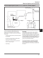
Fuel System (Gasoline)
The typical fuel system includes the fuel tank, in-line
fuel filter, fuel pump, carburetor, and fuel lines. Some
applications use gravity feed without a fuel pump.
Operation
The fuel from the tank is moved through the in-line
filter and fuel lines by the fuel pump. On engines not
equipped with a fuel pump, the fuel tank outlet is
located above the carburetor inlet and gravity moves
the fuel.
Fuel then enters the carburetor float bowl and is
moved into the carburetor body. There, the fuel is
mixed with air. This fuel-air mixture is then burned in
the engine combustion chamber.
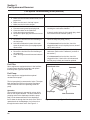
Troubleshooting
Use the following procedure to check for a suspected
fuel delivery problem.
5.1
5
Section 5
Fuel System and Governor
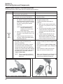
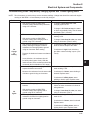
Fuel System Troubleshooting Guide (Gasoline)
Test
1. Check for the following:
a. Make sure the fuel tank contains clean, fresh,
proper fuel.
b. Make sure the vent in fuel cap is open.
c. Make sure the fuel valve is open.
2. Check for fuel in the combustion chamber.
a. Disconnect and ground spark plug lead.
b. Close the choke on the carburetor.
c. Crank the engine several times.
d. Remove the spark plug and check for fuel at
the tip.
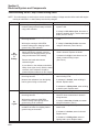
3. Check for fuel flow from the tank to the fuel pump.
a. Remove the fuel line from the inlet fitting of
the fuel pump.
b. Hold the line below the bottom of the tank.
Open the shutoff valve (if so equipped) and
observe flow.
4. Check the operation of fuel pump.
a. Remove the fuel line from the inlet fitting of
the carburetor.
b. Crank the engine several times and observe
flow.
Conclusion
2. If there is fuel at the tip of the spark plug, fuel is
reaching the combustion chamber.
If there is no fuel at the tip of the spark plug, check
for fuel flow from the fuel tank (Test 3).
3. If fuel does flow from the line, reconnect line and
check for faulty fuel pump (Test 4).
If fuel does not flow from the line, check for
clogged fuel tank vent, fuel pickup screen, shutoff
valve, and fuel lines.
4. If fuel does flow from the line, check for faulty
carburetor. (Refer to the "Carburetor" portions of
this section.)
If fuel does not flow from the line, check for
clogged fuel line. If the fuel line is unobstructed,
the fuel pump is faulty and must be replaced.
Fuel Filter
Some engines are equipped with an in-line fuel filter.
Visually inspect the filter periodically, and replace
when dirty with a genuine Kohler filter.
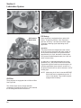
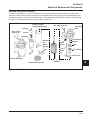
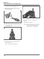
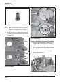
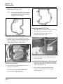
Outlet Check Valve
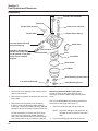
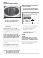
Camshaft
Fuel Pump
Some engines are equipped with an optional
mechanical fuel pump.
The fuel pump body is constructed of nylon. The nylon
body insulates the fuel from the engine crankcase.
This prevents the fuel from vaporizing inside the
pump.
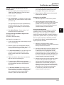
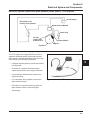
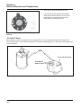
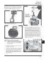
Operation
The mechanical pump is operated by a lever which
rides on the engine camshaft. The lever transmits a
pumping action to the diaphragm inside the pump
body. On the downward stroke of the diaphragm,
fuel is drawn in through the inlet check valve. On the
upward stroke of the diaphragm, fuel is forced out
through the outlet check valve. See Figure 5-1.
5.2
Fuel Pump
Lever
Diaphragm
Inlet Check Valve
Figure 5-1. Cutaway - Typical Fuel Pump.
Section 5
Fuel System and Governor
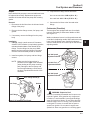
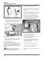
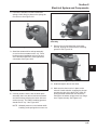
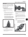
3. Torque the hex. flange screws as follows:
Repair
Nylon-bodied fuel pumps are not serviceable and must
be replaced when faulty. Replacement pumps are
available in kits that include the pump and mounting
gasket.
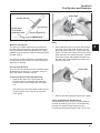
Removal
1. Disconnect the fuel lines from the inlet and outlet
fittings of the pump.
Into new as-cast hole–9.0 N·m (80 in. lb.).
Into used hole–4.2-5.1 N·m (37-45 in. lb.).
4. Connect the fuel lines to the inlet and outlet
fittings.
Carburetor (Gasoline)
2. Remove the hex. flange screws, fuel pump, and
gasket.
3. If necessary, remove the fittings from the pump
body.
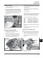
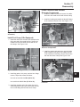
Installation
1. Fittings - Apply a small amount of Permatex®
Aviation Perm-A-Gasket (or equivalent) gasoline
resistant thread sealant to the threads of the
fittings. Turn the fittings into the pump 5 full
turns; continue turning the fittings in the same
direction until the desired position is reached.
2. Install new gasket, fuel pump, and hex. flange
screws.
NOTE: Make sure the fuel pump lever is
positioned to the right of the camshaft
(when looking at fuel pump mounting
pad). Damage to the fuel pump, and
severe engine damage, could result if
the lever is positioned to the left of the
camshaft.
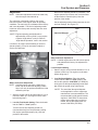
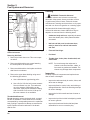
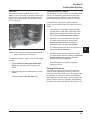
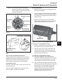
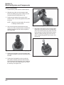
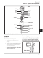
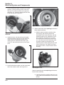
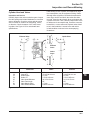
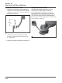
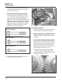
These engines are equipped with one of two basic
types of fixed main jet carburetors–Walbro or Nikki.
See Figure 5-3.
Walbro carburetors have a low idle speed screw and
a low idle fuel adjusting needle. Nikki carburetors only
have a low idle speed screw. Certified carburetors
will have fixed idle fuel or a limiter cap on the idle fuel
adjusting needle.
Walbro
Low Idle Speed
Adjustment Screw
Low Idle Fuel
Adjustment Needle
Nikki
Low Idle Speed
Adjustment Screw
Hex. Flange Screw (2)
Fuel Pump
Gasket
Figure 5-3. Carburetor Adjustment.
Fuel Fittings
Figure 5-2. Installing Fuel Pump.
WARNING: Explosive Fuel!
Gasoline is extremely flammable and its vapors can
explode if ignited. Store gasoline only in approved
containers, in well ventilated, unoccupied buildings,
away from sparks or flames. Do not fill the fuel tank
while the engine is hot or running, since spilled fuel
could ignite if it comes in contact with hot parts or
sparks from ignition. Do not start the engine near
spilled fuel. Never use gasoline as a cleaning agent.
5.3
5
Section 5
Fuel System and Governor
Troubleshooting - Gasoline Systems
•
Make sure the air cleaner base and carburetor
are securely fastened to the engine using gaskets
in good condition.
•
Make sure the air cleaner element is clean and all
air cleaner components are fastened securely.
•
Make sure the ignition system, governor system,
exhaust system, and throttle and choke controls
are operating properly.
If engine troubles are experienced that appear to be
fuel system related, check the following areas before
adjusting or disassembling the carburetor.
•
Make sure the fuel tank is filled with clean, fresh
gasoline.
•
Make sure the fuel tank cap vent is not blocked
and that it is operating properly.
•
Make sure fuel is reaching the carburetor. This
includes checking the fuel shut-off valve, fuel tank
filter screen, in-line fuel filter, fuel lines, and fuel
pump for restrictions or faulty components as
necessary.
If, after checking the items listed above, starting
problems or conditions similar to those listed in the
following table exist, it may be necessary to adjust or
service the carburetor.
Troubleshooting - Gasoline Fuel Systems Carburetor
Condition
Possible Cause/Probable Remedy
1. Engine starts hard, runs roughly
or stalls at idle speed.
2. Engine runs rich. (Indicated by
black, sooty exhaust smoke,
misfiring, loss of speed and power,
governor hunting, or excessive
throttle opening).
1. Low idle fuel mixture/speed improperly adjusted. Adjust the low
idle speed screw, then adjust the low idle fuel needle.
2a. Choke partially closed during operation. Check the choke lever/
linkage to ensure choke is operating properly.
b. Low idle fuel mixture is improperly adjusted. Adjust low idle fuel
needle.
c. Float level is set too high. With fuel bowl removed and carburetor
inverted, the exposed surface of float must be parallel with the
bowl gasket surface of the carburetor body.
d. Dirt under fuel inlet needle. Remove needle; clean needle and
seat and blow with compressed air.
e. Bowl vent or air bleeds plugged. Remove fuel bowl, low idle fuel
adjusting needle, and welch plugs. Clean vent, ports, and air
bleeds. Blow out all passages with compressed air.
f. Fuel bowl gasket leaks. Remove fuel bowl and replace gasket.
g. Leaky, cracked, or damaged float. Submerge float to check for
leaks.
3. Engine runs lean. (Indicated by
misfiring, loss of speed and power,
governor hunting, or excessive
throttle opening).
3a. Low idle fuel mixture is improperly adjusted. Adjust low idle fuel
needle.
b. Float level is set too low. With fuel bowl removed and carburetor
inverted, the exposed surface of float must be parallel with the
bowl gasket surface of the carburetor body.
c. Idle holes plugged; dirt in fuel delivery channels. Remove fuel
bowl, low idle fuel adjusting needle, and welch plugs. Clean main
fuel jet and all passages; blow out with compressed air.
4a. Float level set too high. See Remedy 2c.
b. Dirt under fuel inlet needle. See Remedy 2d.
c. Bowl vent plugged. Remove fuel bowl and clean bowl vent. Blow
out with compressed air.
d. Float is cracked or damaged. Replace float.
e. Bowl retaining screw gasket damaged. Replace gasket.
f. Bowl retaining screw loose. Torque screw to specifications.
4. Fuel leaks from carburetor.
5.4
Section 5
Fuel System and Governor
Adjustment
NOTE: Carburetor adjustments should be made only
after the engine has warmed up.
The carburetor is designed to deliver the correct
fuel-to-air mixture to the engine under all operating
conditions. The main fuel jet is calibrated at the factory
and is not adjustable*. The idle fuel adjusting needle
is also set at the factory and normally does not need
adjustment.
Now turn the adjusting needle in (clockwise). The
engine speed may increase, then it will decrease
as the needle is turned in (lean). Note the
position of the needle.
Set the adjusting needle midway between the rich
and lean settings. See Figure 5-5.
Lean
Adjust to Midpoint
*NOTE: Engines operating at altitudes above
approximately 1830 m (6000 ft.) may require
a special ‘‘high altitude’’ main jet. Refer to
‘‘High Altitude Operation’’ later in this section.
If, however, the engine is hard-starting or does not
operate properly, it may be necessary to adjust or
service the carburetor.
Low Idle
Speed Screw
Rich
5
Figure 5-5. Optimum Low Idle Fuel Setting.
Nikki Carburetor Adjustment
NOTE: Certified engines have the idle mixture preset
and sealed at the factory. No adjustment is
possible.
Low Idle
Fuel Needle
Figure 5-4. Fixed Main Jet Carburetor.
Walbro Carburetor Adjustment
NOTE: Certified engines may have a fixed idle or
limiter cap on the idle fuel adjusting needle.
Step 2 can only be performed within the limits
allowed by the cap.
1. Start the engine and run at half throttle for 5 to 10
minutes to warm up. The engine must be warm
before doing step 2.
2. Low Idle Fuel Needle Setting: Place the throttle
into the "idle" or "slow" position.
Low Idle Speed Setting
1. Start the engine and run at half throttle for 5 to 10
minutes to warm up. The engine must be warm
before doing step 2.
2. Low Idle Speed Setting: Place the throttle
control into the "idle" or "slow" position. Set
the low idle speed to 1200 RPM* (±75 RPM) by
turning the low idle speed adjusting screw in or
out. Check the speed using a tachometer.
*NOTE: The actual low idle speed depends
on the application–refer to equipment
manufacturer's recommendations. The
recommended low idle speed for basic
engines is 1200 RPM. To ensure best
results when setting the low idle fuel
needle, the low idle speed must not
exceed 1200 RPM (±75 RPM).
Turn the low idle fuel adjusting needle out
(counterclockwise) from the preliminary setting
until engine speed decreases (rich). Note the
position of the needle.
5.5
Section 5
Fuel System and Governor
Disassembly
Throttle Lever and Shaft
Dust Seal
Throttle Plate Screw(s)
Choke Lever and Shaft
Choke Return Spring
Throttle Plate
Low Idle Speed Adjusting
Screw and Spring
Low Idle Fuel Adjusting
Needle and Spring (may
not be present or may have
limiter cap on certified
engines)
Choke Plate
Fuel Inlet Seat
Float
Fuel Inlet Needle
Float Shaft
Bowl Gasket
Fuel Bowl
Bowl Retaining Screw Gasket
Fuel Shut-off Solenoid
or
Bowl Retaining Screw
Figure 5-6. Carburetor - Exploded View.
1. Remove the bowl retaining screw, retaining screw
gasket, and fuel bowl.
2. Remove the bowl gasket, float shaft, float, and fuel
inlet needle.
3. Remove the low idle speed screw and spring.
If there is a low fuel adjusting needle without a
limiter cap, remove the needle and spring. Do not
attempt to remove the needle if it has a limiter cap.
Further disassembly to remove the welch plugs,
main fuel jet, fuel inlet seat, throttle plate and
shaft, and choke plate and shaft is recommended
only if these parts are to be cleaned or replaced.
5.6
Welch Plug Removal–Walbro Carburetors
In order to clean the idle ports and bowl vent
thoroughly, remove the welch plugs covering these
areas.
Use Tool No. KO1018 and the following procedure to
remove the welch plugs. See Figure 5-7.
1. Pierce the welch plug with the tip of the tool.
NOTE: To prevent damage to the carburetor, do
not allow the tool to strike the carburetor
body.
2. Pry out the welch plug with the tip of the tool.
Section 5
Fuel System and Governor
Choke Plate
Tool No. KO1018
Do Not Allow
Tip to Strike
Carburetor Body
Pry Out Plug
Pierce Plug with Tip
Carburetor Body
Welch Plug
Figure 5-7. Removing Welch Plug.
Main Fuel Jet Removal
The main jet on Walbro carburetors is pressed into
the side of the tower portion of the body. Removal is
not recommended, unless a high-altitude kit is being
installed, in which case the removal instructions will be
included in the kit.
The main jet on Nikki carburetors is threaded into the
tip of the fuel shut-off solenoid. It can be removed for
inspection or cleaning.
Fuel Inlet Seat Removal
The fuel inlet seat is pressed into the carburetor body,
do not attempt to remove it. If necessary, clean it in
place with aerosol carburetor cleaner.
Figure 5-8. Marking Choke Plate and Carburetor
Body.
2. Some carburetors have the choke plate inserted
into a slot in the choke shaft. Grasp the choke
plate with a pliers and pull it out of the slot. See
Figure 5-9. Other carburetors will have the choke
plate fastened to the shaft with screws. Carefully
remove the screws and separate the plate from
the shaft. Use a fine-toothed file to remove any
burrs from the shaft.
Choke Plate
Choke Shaft Removal (Non-Self-Relieving)
1. Because the edges of the choke plate are
beveled, mark the choke plate and carburetor
body to ensure correct reassembly. See Figure
5-8.
Also take note of the choke plate position in bore,
and the position of the choke lever and choke
return spring.
Figure 5-9. Removing Choke Plate.
3. Remove the choke shaft and choke return spring.
Choke Shaft Removal (Self-Relieving)
The self-relieving choke, used on some carburetors
is shown in cutaway Figure 5-10. Use the following
procedure to replace the self-relieving choke
components using Choke Repair Kit No. 12 757 11-S.
5.7
5
Section 5
Fuel System and Governor
Cleaning
Dust Cap
Choke Lever
Spring
Brass
Bushing
Stop Pin
Choke
Valve
Screws
Figure 5-10. Cutaway View Showing Self-Relieving
Choke Carburetor.
Removing Old Parts
1. Remove the black dust cover. This cover snaps
on and off.
WARNING: Flammable Solvents!
Carburetor cleaners and solvents are extremely
flammable. Keep sparks, flames, and other sources
of ignition away from the area. Follow the cleaner
manufacturer’s warnings and instructions on its proper
and safe use. Never use gasoline as a cleaning agent.
All parts should be cleaned thoroughly using a
commercial carburetor cleaner. Make sure all gum
deposits are removed from the following areas.
•
Carburetor body and bore; especially the areas
where the throttle plate, choke plate and shafts
are seated.
•
Idle fuel and idle ports in carburetor bore,
main jet, bowl vent, and fuel inlet needle
and seat.
•
Float and float hinge.
•
Fuel bowl.
•
Throttle plate, choke plate, throttle shaft, and
choke shaft.
2. Remove and discard the two screws fastening
the choke plate to the choke shaft.
NOTE: Do not submerge the carburetor in
cleaner or solvent when fiber, rubber, or
foam seals or gaskets are installed. The
cleaner may damage these components.
3. Remove and discard the choke plate and choke
shaft from the carburetor.
4. Remove the upper brass bushing using one of
the following procedures:
a. Use a slide hammer type bearing puller.
b. Use a #3 (for 5/32 dia. hole) screw extractor.
Secure extractor in a vise. Turn carburetor
on to the extractor. While pulling on the
carburetor, lightly tap the carburetor casting
with a hammer or use a size 12-28 tap if a
#3 screw extractor is not available.
Throttle Shaft Removal
Do not attempt to remove the throttle shaft, as repair
kits are not available. Throttle shaft wear is normally
accompanied by corresponding wear to the carburetor
body, making it impractical to attempt a cost-effective
repair. Replace the entire carburetor if the throttle
shaft is worn.
5.8
Inspection
Carefully inspect all components and replace those
that are worn or damaged.
•
Inspect the carburetor body for cracks, holes, and
other wear or damage.
•
Inspect the float for cracks, holes, and missing or
damaged float tabs. Check the float hinge and pin
for wear or damage.
•
Inspect the fuel inlet needle and seat for wear or
damage.
•
Inspect the tip of the low idle fuel adjusting needle
for wear or grooves.
•
Inspect the throttle and choke shaft and plate
assemblies for wear or excessive play.
Section 5
Fuel System and Governor
Repair
Always use new gaskets when servicing or reinstalling
carburetors. Repair kits are available which include
new gaskets and other components. Always refer to
the Parts Manual for the engine being serviced to
ensure the correct repair kits are ordered.
Reassembly
Choke Shaft Installation (Non-Self-Relieving)
1. Install the choke return spring to the choke shaft.
2. Insert the choke shaft with return spring into the
carburetor body.
3. Rotate the choke lever approximately 1/2 turn
counterclockwise. Make sure the choke return
spring hooks on the carburetor body.
4. Position the choke plate as marked during
disassembly. Insert the choke plate into the slot
in the choke shaft. Make sure the choke shaft is
locked between the tabs on the choke plate. If the
choke plate was attached with screws, loosely
attach the plate to the shaft. Close the choke and
center the choke plate in the bore. Tighten, but do
not over-tighten the screws. Check that the choke
moves freely and that the plate does not bind in
the bore.
Choke Shaft Installation (Self-Relieving)
WARNING: Prevent Eye Injury!
Suitable eye protection (safety glasses, goggles,
or face shield) should be worn for any procedure
involving the use of compressed air, punches,
hammers, chisels, drills, or grinding tools.
1. Before installing kit parts, thoroughly clean the
carburetor body with compressed air.
2. Install the new bushing through the new lever and
align the slot in the bottom of the lever over the
lever stop pin. To ensure the proper alignment of
the upper bushing and the lower shaft hole use a
3/16 diameter drill blank to align the bushing as it
is pressed into the casting.
3. Install choke shaft and spring assembly with the
lower spring tang installed in the second notch
from the right. See Figure 5-11.
Top View Showing
Spring Position
Bottom of
Spring in
Position 2
Figure 5-11. Choke Lever with Cap Removed.
4. Loosely attach the choke plate to the choke
shaft using the two screws provided in the choke
repair kit. Apply Loctite® No. 609 to the threads of
the choke plate retaining screws. Secure these
screws ONLY after the choke plate is properly
aligned in the choke bore. To align choke plate,
insert a .010 in. shim between the top right edge
of the choke plate and bore. See Figure 5-12.
Then while pushing down on the top of the choke
shaft, tighten screws securely.
Figure 5-12. Measuring Clearance.
5. Check choke shaft and choke plate for freedom
of movement by performing the following:
a. Using the choke lever, close the choke plate.
The choke lever and choke plate should
move in unison.
b. While holding the choke lever in the closed
position, push on the long side of the choke
plate. The choke plate should open and
spring closed freely.
c. While holding the choke lever in the wide
open position, the choke plate should be
against the wide open choke plate stop pin.
6. Install new dust cover by pushing it down until it
snaps into place.
7. After the carburetor is reinstalled on the engine,
recheck choke system for freedom of movement
by moving the wire link in the direction to close
the choke and releasing it. The link should move
freely in both directions.
5.9
5
Section 5
Fuel System and Governor
Welch Plug Installation–Walbro Carburetors
Use Tool No. KO1017 and install new plugs as follows:
1. Position the carburetor body with the welch plug
cavities to the top.
4. Insert the fuel inlet needle into the float. Lower
the float/needle into the carburetor body. See
Figure 5-14.
Install the float shaft.
2. Place a new welch plug into the cavity with the
raised surface up.
Float
3. Use the end of the tool that is about the same
size as the plug and flatten the plug. Do not force
the plug below the surface of the cavity. See
Figure 5-13.
Fuel Inlet Needle
Tool No. KO1017
Figure 5-14. Installing Float and Fuel Inlet Needle.
Carburetor Body
New Welch Plug
5. Install the bowl gasket, fuel bowl, bowl retaining
screw gasket, and bowl retaining screw or fuel
solenoid.
Torque the bowl retaining screw to 5.1-6.2 N·m
(45-55 in. lb.).
Figure 5-13. Installing Welch Plugs.
4. After the plugs are installed, seal them with
Glyptal™ (or an equivalent sealant). Allow the
sealant to dry.
NOTE: If a commercial sealant is not available,
fingernail polish can be used.
Carburetor Reassembly
1. Install the low idle speed adjusting screw and
spring.
2. If removed during disassembly, install the low
idle fuel adjusting needle and spring. Turn the
adjusting needle in (clockwise) until it bottoms
lightly.
NOTE: The tip of the idle fuel adjusting needle is
tapered to critical dimensions. Damage
to the needle and the seat will result if
the needle is forced.
3. Turn the low idle fuel adjusting needle out
(counterclockwise) 1 turn.
5.10
High Altitude Operation
When operating the engine at altitudes of 1830 m
(6000 ft.) and above, the main fuel mixture tends to
get overrich. An overrich mixture can cause conditions
such as black, sooty exhaust smoke, misfiring, loss
of speed and power, poor fuel economy, and poor or
slow governor response.
To compensate for the effects of high altitude, a
special high altitude main fuel jet can be installed.
High altitude jets are sold in kits which include the jet
and necessary gaskets. Refer to the Parts Manual for
the engine being serviced for the correct kit number.
Fuel Shut-off Solenoid (Optional)
Some gasoline-fueled engines are equipped with
the optional fuel shut-off solenoid, which is installed
in place of the bowl retaining screw, to eliminate
backfiring when the engine is shut down. If a solenoidequipped engine will not start, check whether sufficient
voltage is reaching the solenoid. A minimum of 7.3
volts DC is required to activate the solenoid. Also
check to see that the ground lead from the carburetor
body to the air cleaner base mounting stud is properly
connected.
Section 5
Fuel System and Governor
If these check out, the solenoid should be removed
for bench testing. Remember to shut off fuel supply
and catch any fuel spilling from the carburetor as the
solenoid is removed.
Bench test the solenoid by grounding the solenoid
case and applying 12 volt DC to the spade terminal. If
the plunger does not retract in this test, the solenoid
is faulty and must be replaced. Always use a new fuel
bowl gasket whenever the solenoid is installed. Refer
to the appropriate wiring diagram in Section 8 for
connecting the fuel shut-off solenoid.
LPG Systems
Components of a typical LPG (liquefied propane gas)
system are shown in Figure 5-15. This subsection
covers standard systems as shown in Figure 5-15 and
engines equipped with the Kohler Emission Sentry™
System.
WARNING: Explosive Fuel!
LPG is extremely flammable and is heavier than air
and tends to settle in low areas where a spark or
flame could ignite the gas. Do not start or operate this
engine in a poorly ventilated area where leaking gas
could accumulate and endanger the safety of persons
in the area.
LPG fuel consists primarily of propane, although the
fuel supplier may sometimes mix other gases with
propane.
Fuel tanks must be filled only by persons qualified in
the handling of LPG. Tanks are filled by weight and
should not be overfilled (never to more than 80% of
total capacity). An air space must be present in the
tank to allow fuel to expand.
Tanks must be removed from equipment before filling.
Fuel Recommendations (LPG)
WARNING: Pressurized LPG!
Fuel tanks are filled under pressure and should be
handled with care. To prevent tank damage which
could endanger the safety of the operator or persons
in the area, do not drop or drag tanks on any surface.
Use a hand truck when moving, or tilt the tank on its
footring in a position slightly off vertical and roll it.
Avoid personal contact with LPG fuel to prevent
frostbite. See a physician if frostbite occurs.
LP Carburetor
High Pressure Lines
Vacuum* Lines
Fuel
Delivery
Line
Dry Gas Filter
Dry Gas Regulator
*On some applications the vacuum
line goes directly into the intake
side of the cylinder head.
Automatic Shut-off
Valve (Vacuum Lockoff,
maybe part of regulator)
Propane Supply Tank
(Vapor Withdrawal)
Figure 5-15. Schematic Showing Components of Typical LPG System.
5.11
5
Section 5
Fuel System and Governor
Troubleshooting - LPG Systems
Adjust Carburetor
If engine troubles are experienced that appear to be
caused by the carburetor, check the following areas
before adjusting the carburetor.
•
1. With the engine stopped, reset the main fuel
setting by closing the adjusting screw until it
bottoms then turn it 2 1/4 to 2 1/2 turns open
(see Figure 5-16).*
Make sure the air cleaner element is clean and
all air cleaner components are fastened securely.
This is especially critical on propane-fueled
engines.
•
Check for a loose or kinked vacuum line, causing
regulator not to open.
•
Check to make sure the fuel valve on the LPG
tank is fully opened.
•
Vacuum Line
Main Fuel Set
2 1/4 to 2-1/2
Turns Open
Check gauge on LPG tank to make sure there is
sufficient fuel present.
If, after checking the items listed above, adjust or
service the carburetor as follows.
Fuel Inlet from
Regulators
Adjustable Type Only
Figure 5-16. LPG Main Fuel Setting.*
*NOTE: Engines equipped with Kohler Emission
Sentry™ controls have a fixed main jet
carburetor.
3 Way Catalytic
Muffler (Not Shown)
DC Stepper Motor
Oxygen Sensor
Coupling
Adjustable
Load Screw
Electronic
Control Unit
LPG Carburetor
Shown with
Self-Relieving
Choke
Fuel Metering
Valve Body
To Unit
Wiring Harness
(12 Volt Source)
Figure 5-17. Main Components of Kohler Emission Sentry™ System.
5.12
Section 5
Fuel System and Governor
Kohler Emission Sentry™ System
Some Kohler Command engines are equipped with
the Emission Sentry™ System. Emission Sentry™ is a
feature which assures the operator that the exhaust
emission levels of the engine are well within safe
exposure limits. The system does not require any
additional daily maintenance beyond the schedule
normally specified for Command engines.
Principle of Operation
The Emission Sentry™ System can be broken down
into two functions. One function is to control the
ratio of air and fuel entering the engine. The second
function is treating the exhaust gas, utilizing a 3-way
catalytic converter.
The function of air/fuel ratio control is carried out
by an oxygen sensor placed in the exhaust stream,
an electronic control unit, a stepper motor, and a
fuel metering valve. The oxygen sensor indirectly
measures the oxygen level in the exhaust stream. An
abundance of oxygen indicates a lean condition and a
lack of oxygen indicates a rich condition. The sensor
sends an electrical signal to the electronic control unit
where the signal is analyzed. The electronic control
unit then sends a signal to the stepper motor which
adjusts the fuel metering valve, thus controlling the
amount of fuel entering the engine. The air/fuel ratio
is maintained within a set band under all operating
conditions. By maintaining the air/fuel ratio at peak
performance levels, maximum efficiency is also
realized from the 3-way catalytic converter to further
reduce emissions.
Operating with Emission Sentry™
The equipment has a 12-volt battery and the engine
has an integral electric starter and charging system.
Starting is accomplished by simply setting the throttle/
choke control and activating the key switch on the
dash panel of the unit. When the engine starts, a
green, light emitting diode (LED) will illuminate, to
indicate that the Emission Sentry™ is on. It will require
a warm-up period of about sixty seconds to allow
the oxygen sensor to heat up, and the fuel metering
valve to stabilize. When first started, the engine will
be running rich and may sound rough. As the oxygen
sensor heats up and the system stabilizes, however,
operation should become progressively smoother.
After the system has stabilized (about 1 minute),
operation of the equipment can begin.
The oxygen sensor continually monitors the emission
levels in the exhaust while the unit is running. If the
emission levels exceed a predetermined level, a fault
detection circuit will be activated in the electronic
control unit. Once activated, the fault detection circuit
will continue to monitor the signal from the oxygen
sensor for the next 45-60 seconds. If the emission
levels remain at an unsafe level, the fault circuit will
ground the ignition to kill the engine and illuminate a
red LED lamp on the dash panel of the unit. The
fault circuit will reset itself automatically in about 2-3
minutes. If the fault circuit is triggered repeatedly, one
of the components is malfunctioning or faulty, and
the unit should be serviced by an authorized dealer.
The fault circuit will not allow the engine to operate
more than 45-60 seconds with emissions above the
predetermined level.
Troubleshooting the Emission
Sentry™ System
If the fault circuit is triggered repeatedly during
operation, a fault should be suspected in one of the
following areas:
a. Electrical wires for stepper motor, oxygen
sensor, battery cable, or ground cable have been
disconnected.
b. Stepper motor.
c. Fuel adjusting screw in control valve is binding.
d. Oxygen sensor.
e. Electronic control unit.
If the fault circuit is triggered when the engine is idling:
a. The idle mixture screw on the gas regulator may
be improperly adjusted.
To determine where the fault lies, proceed as follows:
1. Check all electrical connections and leads from
oxygen sensor, stepper motor, electronic control
unit and battery cables. It is best to disconnect
wire connectors from oxygen sensor, stepper
motor and engine functions and check for
corrosion. Reconnect and observe if fault occurs
again.
5.13
5
Section 5
Fuel System and Governor
2. The stepper motor, electronic control unit
(ECU) and oxygen sensor can all be checked
with the Kohler Emission Sentry™ Tester (Kohler
Part No. 12 761 07-S).
a. Separate the plug connector between the
electronic control unit (ECU) and the stepper
motor. Plug the separated connectors into
the mating connectors on the Emission
Sentry™ Tester. Connect the single black
lead to battery negative or a good ground
on the engine/unit. Turn the key switch on
the dash to the ‘‘run’’ position, and push
the small toggle switch on the tester to the
‘‘open’’ position. Observe the red LED’s
for the ECU and the bicolor LED’s for the
stepper motor. The red LED’s should flash in
sequence, the bicolor LED’s should alternate
colors, and you should hear the stepper
motor turning. Now push the toggle switch
to the ‘‘close’’ position and repeat your
observations. The red LED’s should flash
in the reverse sequence, the bicolor LED’s
should again alternate, and you should again
hear the stepper motor turning. If any or all
of the red LED’s are not flashing, the ECU is
faulty. If the bicolor LED’s are not alternating
and/or the stepper motor is not running, the
stepper motor is faulty.
b. Allow the toggle switch on the tester to return
to the ‘‘monitor’’ position, start the engine,
and place the throttle between midrange
and fast. Observe the LED’s on the tester.
The red and bicolor LED’s should flash as in
the previous test. The green LED (oxygen
sensor) will be off initially, unless the muffler
is still hot from prior running. As the oxygen
sensor reaches operating temperature, the
green LED should begin to flash on and off.
If it stays on or off, or the interval between
flashes is more than 25-30 seconds, the
oxygen sensor could be faulty or the load
adjusting screw in the fuel metering valve
may be stuck or binding. Proceed to step 3.
3. Remove the stepper motor/fuel metering valve
assembly from the engine. Remove the four
small socket head screws and separate the fuel
metering valve from the stepper motor. Try to
turn the load adjusting screw with the blade of a
small screwdriver (see inset in Figure 5-17). If the
screw turns freely and easily, the oxygen sensor
was faulty (step 2b).
5.14
If the screw is stuck or binding, remove it from the
valve body, clean the threads with solvent, and
reinstall. Check it again for binding. Do not use
any type of lubricant on the threads of the load
adjusting screw.
NOTE: If the oxygen sensor is removed from
the exhaust manifold for any reason, a
high temperature anti-seize compound
(Loctite® No. 767) should be applied to
the threads. A new replacement sensor
already has a dry anti-seize compound
on the threads; additional compound is
not required.
4. If the fault circuit triggers while the engine is
idling, but not during normal operation, the
idle mixture screw on the regulator is probably
out of adjustment. Turn the screw 1/2 turn
clockwise, start the engine, and run it at idle for
approximately two minutes. If the fault circuit
does not trigger, the problem has been corrected.
If the fault circuit is triggered and the engine
shuts off before two minutes, turn the screw an
additional 1/4 turn clockwise and test again for
two minutes.
Governor
These engines are equipped with a centrifugal
flyweight mechanical governor. It is designed to hold
the engine speed nearly constant under changing load
conditions. The governor gear/flyweight mechanism
is mounted inside the crankcase and is driven off the
gear on the balance shaft.
Operation
As the governor gear rotates, centrifugal force causes
the flyweights to move outward as speed increases.
As the flyweights move outward, they cause the
regulating pin to move outward.
The regulating pin contacts the tab on the cross
shaft, causing the shaft to rotate when the engine
speed changes. One end of the cross shaft protrudes
through the side of the crankcase. Through external
linkage attached to the cross shaft, the rotating action
is transmitted to the throttle lever of the carburetor.
Section 5
Fuel System and Governor
When the engine is at rest, and the throttle is in the
‘‘fast’’ position, the tension of the governor spring
holds the throttle plate open. When the engine is
operating (the governor gear assembly is rotating), the
force applied by the regulating pin against the cross
shaft tends to close the throttle plate. The governor
spring tension and the force applied by the regulating
pin are in ‘‘equilibrium‘‘ during operation, holding the
engine speed nearly constant.
1. With the governor lever loose on the cross shaft,
pull the lever towards the carburetor (wide open
throttle).
2. Grasp the cross shaft with a pliers, or insert a nail
into the hole in the end of the cross shaft. Rotate
the shaft counterclockwise as far as it will turn,
then tighten hex. nut securely.
3. Torque the hex. nut to 9.9 N·m (88 in. lb.).
When load is applied and the engine speed (and
governor gear speed) decreases, the governor spring
tension moves the governor arm to open the throttle
plate wider. This allows more fuel into the engine;
increasing engine speed. This action takes place very
rapidly, so a reduction in speed is hardly noticed. As
the speed reaches the governed setting, the governor
spring tension and the force applied by the regulating
pin will again be in equilibrium. This maintains the
engine speed at a relatively constant level.
The governed speed setting is determined by the
position of the throttle control. It can be variable or
constant, depending on the application.
Unitized Throttle and Choke Control
Some engines are equipped with a ‘‘unitized’’ throttle
and choke control bracket assembly. This assembly
controls the choke and engine speed with a single
lever.
Throttle Control Cable
Speed
Control
Bracket
Initial Adjustment
Make this initial adjustment whenever the governor
arm is loosened or removed from the cross shaft. To
ensure proper setting, make sure the throttle linkage
is connected to the governor arm and the throttle lever
on the carburetor. See Figure 5-18.
Governor Lever
5
Throttle Cable Adjustment
1. Loosen the throttle control cable clamp. See
Figure 5-19.
Clamp
Sight
Hole
Throttle
Lever
Choke Adjusting
Screw
Figure 5-19. Speed Control Bracket Assembly.
Alignment Holes
2. Place the throttle control lever of the equipment
into the “fast” or high idle position.
Cross Shaft
Hex. Nut
Figure 5-18. Initial Governor Adjustment.
NOTE: The choke is placed “on” by moving the
throttle control slightly past the “fast”
position. If the throttle control does not
have a designated choke “on” position,
be sure to leave sufficient throttle control
travel past the “fast” position. This will
enable the choke to be placed “on”. See
Figure 5-20.
NOTE: Air cleaner removed to show linkage.
Adjustment should be made with air cleaner
base installed.
5.15
Section 5
Fuel System and Governor
1. Make sure the throttle cable is adjusted properly
(see ‘‘Throttle Cable Adjustment").
2. Start the engine and allow it to warm up. Place
the throttle control lever into the ‘‘fast’’ or high idle
position.
3. Align the hole in the throttle lever with the hole in
the speed control bracket by inserting a pencil or
6.35 mm (1/4 in.) drill bit. See Figure 5-21.
Cold Engine
Warm Engine
Figure 5-20. Typical Throttle/Choke Controls.
4. Loosen the speed control bracket mounting
screws. Move the bracket up or down until the
desired high idle speed is reached. See Figure
5-22. Check the speed with a tachometer.
3. Align the hole in the throttle lever with the hole in
the speed control bracket by inserting a pencil or
6.35 mm (1/4 in.) drill bit. See Figure 5-21.
Speed Control
Bracket
Increase
Speed
Mounting
Screws
Choke Adjusting
Screw
Sight
Hole
Choke Lever
Speed Control
Bracket
Throttle Lever
Decrease Speeds
Choke Adjusting
Screw
Figure 5-22. Adjusting High Idle Speed.
To increase the high idle speed - move the
bracket up (towards flywheel).
Figure 5-21. Aligning Holes in Speed Control
Bracket and Throttle Lever.
4. Pull up on the outer shield of the throttle control
cable to remove any slack. Tighten the cable
clamp securely.
High Idle Speed Adjustment
The recommended maximum no-load high idle speed
for most of these engines is 3750 RPM. The actual
high idle speed depends on the application. Refer to
the equipment manufacturer’s instructions for specific
information.
WARNING: Overspeed is Hazardous!
Do not tamper with the governor setting. Overspeed is
hazardous and could cause personal injury.
5.16
To decrease the high idle speed - move the
bracket down (towards PTO).
5. Tighten the speed control bracket mounting
screws. Recheck the speed with a tachometer
and readjust if necessary.
Torque the mounting screws as follows:
Into new as-cast hole–10.7 N·m (95 in. lb.).
Into used hole–7.3 N·m (65 in. lb.).
6. Adjust the choke (see ‘‘Choke Adjustment’’ which
follows).
Section 5
Fuel System and Governor
Choke Adjustment
This procedure must follow the "High Idle Speed
Adjustment" just described. If not already completed,
perform that operation first.
1. Turn the choke adjusting screw out
(counterclockwise), until it no longer contacts the
choke lever. Then turn it back in (clockwise), until
it just makes contact.
Governor Lever
2. While observing the choke link, move the throttle
control lever to the low idle (slow) position, then
back to full throttle (fast). The choke link should
not move as the throttle moves through the
normal range. If it does, back the adjusting screw
out until it no longer moves.
3. Move the throttle control lever to the choke
position. Check if the choke has fully closed by
placing your finger behind (right side) the link
loop and applying pressure toward the carburetor.
If the controls have been properly set, the link
should not move.
Sensitivity Adjustment
Governor sensitivity is adjusted by repositioning the
governor spring in the holes in the governor arm.
If speed surging occurs with a change in load, the
governor is set too sensitive. If a big drop in speed
occurs when normal load is applied, the governor
should be set for greater sensitivity.
Governor Spring
Figure 5-23. Governor Spring Location.
Speed Control Bracket Service
The only serviceable components of the speed control
bracket assembly are the choke adjusting screw and
spring, choke return spring, and throttle cable clamp
and screw. Install the choke return spring as shown.
See Figure 5-24.
Replace the assembly if other parts are worn or
damaged.
Throttle Cable
Clamp and
Screw
Speed
Control
Bracket
Assembly
The position of the governor spring in the governor
arm depends on the high idle, no load speed setting
(see Figure 5-23):
If the high idle, no load speed is 3600 RPM or less
- use the #2 hole (count outward from cross shaft).
If the high idle speed is greater than 3600 RPM use the #3 hole (count outward from cross shaft).
Choke Adjusting
Screw and Spring
Choke
Return
Spring
Figure 5-24. Speed Control Bracket Assembly.
Separate Throttle and Choke Control
Some engines are equipped with separate throttle and
choke controls. This allows you to adjust the choke
and throttle controls individually.
Install Separate Control Cables (See Figure 5-25).
Throttle Control
1. Loosen the 2-cable clamp screws on the engine
control plate.
5.17
5
Section 5
Fuel System and Governor
2. Position the application throttle control in the full
(fast) throttle position. Then move the throttle
lever back 3/16" or 4.75 mm. Insert the cable
boden wire into the throttle control lever on the
control plate.
2. Position the choke cable under the cable clamp.
3. Position the throttle cable under the cable clamp.
4. Push on the choke cable, above the clamp on the
engine control plate, until the choke lever stops.
Then tighten the cable clamp screw.
4. Pull on the throttle cable until it stops, hold it, and
tighten the cable clamp screw.
5. Move application throttle lever to the slow position
then to full throttle. Check the engine control to
assure it stops against the stop screw, which
means it is properly set.
Choke Control
1. Insert the choke cable boden wire into the engine
choke control lever on the control plate.
3. Push the choke (knob/handle) in the application
panel until it bottoms, then pull it back
approximately 1/16".
5. Pull the choke knob/handle until it stops, check to
assure the choke link cannot be moved towards
the carburetor by applying finger pressure on the
link loop behind the engine control plate. If the
choke link moves, adjust by following steps 3
and 4.
6. Push the choke knob/handle in until it bottoms.
The choke control link should be free so the
engine does not run on partial choke.
HIGH IDLE
Turn Screw Inward to
decrease RPM.
High Idle Speed
Screw
Turn Screw Outward to
Increase RPM.
Lock Nut
Throttle
Position-1
Choke
Tighten Lock Nut When
Desired RPM Is Obtained.
High Idle RPM
Control Stop Pad
Position- 4
Choke
Throttle
Choke
Throttle
Position-3
Throttle
Figure 5-25. Separate Choke and Throttle Cable Control (4 Positions Shown).
5.18
Choke
Position-2
Section 5
Fuel System and Governor
Starting an Engine Equipped with Separate
Control Cables
1. Place the throttle control midway between the
"slow" and "fast" positions. Place the choke
control into the "on" position.
7. Turn the high idle stop screw inward (clockwise)
until it stops against the throttle control lever.
Then tighten the stop screw retaining nut.
8. Recheck high idle RPM to assure the required
RPM has been obtained.
2. Start the engine.
3. For a Cold Engine – Gradually return the choke
control to the "off" position after the engine starts
and warms up.
The engine/equipment may be operated during
the warm up period, but it may be necessary
to leave the choke partially on until the engine
warms up.
4. For a Warm Engine – Return choke to "off"
position as soon as engine starts.
Changing the High Idle RPM on Engines with
Separate Controls
(Increase or Decrease RPM)
See Figure 5-25 on page 5.18.
1. Loosen the high idle stop screw retaining nut (top
side of control plate).
2. Start the engine, move the application throttle
lever to full throttle/fast, loosen the throttle cable
clamp screw on the engine control plate.
3. To increase the RPM: Turn high idle stop screw
outward (counterclockwise) and pull on the
throttle control cable until the desired RPM is
obtained.
4. Tighten the throttle cable clamp screw and the
high idle stop screw retaining nut.
5. To assure that the RPM has been obtained,
move the throttle lever to low idle/slow then back
to full throttle/fast and check the RPM with a
tachometer.
6. To decrease the RPM: Follow steps 1 and 2.
Then push the throttle cable in toward the control
bracket assembly to decrease the RPM (check
with a tachometer) until the desired RPM is
obtained. Tighten the cable clamp screw.
Setting the Low Idle RPM
1. Move the application control to slow position.
2. Using a tachometer, check the RPM. Then,
using a screwdriver, turn the low idle stop screw
(located at the top of the carburetor) inward
(clockwise) to increase the RPM and outward
(counterclockwise) to lower the RPM.
Governed Idle Adjustment
A new governed idle control system is now being
supplied on some CV Single Cylinder engines.
The purpose of the new system is to maintain a
desired idle speed regardless of ambient conditions
(temperature, parasitic load, etc.) that often change.
The new system requires an additional procedure
for setting the idle speed. If speed adjustments are
required proceed as follows.
1. Make any necessary speed or control
adjustments following the appropriate instructions
already covered in this section.
2. Move the throttle control to the idle position. Hold
the governor lever away from the carburetor,
so the throttle lever is tight against the idle
speed adjusting screw. Check the speed with a
tachometer and adjust it to 900-1000 RPM. Turn
the screw clockwise to increase the speed and
counterclockwise to decrease the speed.
3. Release the governor lever and allow the engine
to return to the governed idle speed. Check
it with a tachometer against the equipment
manufacturers recommended idle speed. If
adjustment is necessary, use the governed idle
adjusting screw on the speed control assembly
(see Figure 5-26). Turn the screw clockwise
to increase the governed idle speed and
counterclockwise to decrease it.
5.19
5
Section 5
Fuel System and Governor
Governed Idle
Adjusting Screw
Figure 5-26. Location of Governed Idle Adjusting
Screw.
5.20
CV11-16
Section
6
CV460-465,
CV490-495
Lubrication
System
Section 6
Lubrication System
Oil Recommendations
Using the proper type and weight of oil in the
crankcase is extremely important. So is checking oil
daily and changing oil regularly. Failure to use the
correct oil, or using dirty oil, causes premature engine
wear and failure. Synthetic oil is recommended for
use in LPG-fueled engines because there is less
oxidation or thickening, and deposit accumulation on
intake valves is substantially reduced.
6
Oil Type
Use high-quality detergent oil of API (American
Petroleum Institute) service class SG, SH, SJ
or higher. Select the viscosity based on the air
temperature at the time of operation as shown in the
following table.
**
*
*Use of synthetic oil having 5W-20 or 5W-30 rating is
acceptable, up to 40°F.
**Synthetic oils will provide better starting in extreme cold
(below -10°F).
Figure 6-1. Viscosity Grades Table.
NOTE: Using other than service class SG, SH, SJ
or higher oil or extending oil change intervals
longer than recommended can cause engine
damage.
Figure 6-2. Oil Container Logo.
Check Oil Level
The importance of checking and maintaining
the proper oil level in the crankcase cannot be
overemphasized. Check oil BEFORE EACH USE as
follows:
1. Make sure the engine is stopped, level, and
is cool so the oil has had time to drain into the
sump.
2. To keep dirt, grass clippings, etc., out of the
engine, clean the area around the oil fill cap/
dipstick before removing it.
3. Unthread and remove the oil fill cap/dipstick; wipe
oil off. Reinsert the dipstick into the tube and rest
the oil fill cap on the tube. Do not thread the cap
onto the tube. See Figure 6-3.
A logo or symbol on oil containers identifies the API
service class and SAE viscosity grade. See Figure
6-2.
6.1
Section 6
Lubrication System
Optional Oil
Filter Drain Plug
Oil Fill Cap/Dipstick
Oil Filter
Oil Fill Tube
Oil Drain Plug
(Carburetor Side)
Figure 6-3. Checking Oil Level.
Optional Oil Sentry™ Pressure Switch
4. Remove the dipstick and check the oil level.
The oil level should be up to, but not over the ‘‘F’’
mark on the dipstick. See Figure 6-4.
Oil Filter
Oil Drain Plug
Operating
Range
Optional Oil Sentry™ Pressure Switch
Figure 6-4. Oil Level Dipstick.
5. If the level is low, add oil of the proper type, up
to the ‘‘F’’ mark on the dipstick. Always check the
level with the dipstick before adding more oil.
NOTE: To prevent extensive engine wear or
damage, always maintain the proper oil
level in the crankcase. Never operate
the engine with the oil level below the
‘‘L’’ mark or over the ‘‘F’’ mark on the
dipstick.
Change Oil and Oil Filter
Change Oil
Change oil after every 100 hours of operation.
Change the oil while the engine is still warm. The oil
will flow more freely and carry away more impurities.
Make sure the engine is level when filling or checking
oil. Change the oil as follows (see Figure 6-5):
6.2
Oil Drain Plug (Starter Side)
Figure 6-5. Oil Drain Plugs, Oil Filter, Oil Filter
Drain Plug, and Optional Oil Sentry™ Switch.
1. Remove the oil drain plug and oil fill cap/dipstick.
Be sure to allow ample time for complete
drainage.
2. Reinstall the drain plug. Make sure it is tightened
to 13.6 N·m (10 ft. lb.) torque.
3. Fill the crankcase, with new oil of the proper type,
to the ‘‘F’’ mark on the dipstick. Always check the
level with the dipstick before adding more oil.
Section 6
Lubrication System
4. Reinstall the oil fill cap/dipstick and tighten
securely.
NOTE: To prevent extensive engine wear or
damage, always maintain the proper oil
level in the crankcase. Never operate
the engine with the oil level below the
‘‘L’’ mark or over the ‘‘F’’ mark on the
dipstick.
Full-Pressure Lubrication System
Operation
This engine uses a full-pressure lubrication system.
This system delivers oil, under pressure, to the
crankshaft, camshaft, balance shaft, and connecting
rod bearing surfaces. In addition to lubricating the
bearing surfaces, the lubrication system feeds oil to
the hydraulic valve lifters.
Change Oil Filter
Replace the oil filter every other oil change (every
200 hours of operation). Always use a genuine
Kohler oil filter.
A high efficiency Gerotor™ oil pump is located in the
oil pan and is driven by the balance shaft. A pressure
relief valve in the oil pan limits the maximum pressure
of the system.
Replace the oil filter as follows:
Service
The oil pump rotors can be serviced without removing
the oil pan. Remove the oil pump cover on the PTO
side of oil pan to service the rotors.
1. Drain the oil from the engine crankcase.
2. Remove the oil filter drain plug (where applicable)
located at the base of the oil filter adapter. Allow
the oil filter to drain.
3. Remove the old filter and wipe off the filter
adapter. Reinstall the oil filter drain plug. Torque
the drain plug to 7.3-9.0 N·m (65-80 in. lb.).
The oil pan must be removed to service the oil pickup
and oil pressure relief valve.
See Figures 6-6 through 6-8. Also refer to the
‘‘Disassembly’’ and ‘‘Reassembly’’ sections for
lubrication system components removal and
installation procedures.
4. Place a new replacement filter in a shallow pan
with the open end up. Pour new oil, of the proper
type, in through the threaded center hole. Stop
pouring when the oil reaches the bottom of the
threads. Allow a minute or two for the oil to be
absorbed by the filter material.
Inner
Rotor
5. Put a drop of oil on your fingertip and wipe it on
the rubber gasket.
6. Install the replacement oil filter to the filter
adapter. Turn the oil filter clockwise until the
rubber gasket contacts the filter adapter, then
tighten the filter an additional 2/3 to 1 turn.
Outer Rotor
Outer Rotor
7. Fill the crankcase with new oil, of the proper type,
to the "F" mark on the dipstick.
Inner
Rotor
8. Test run the engine to check for leaks. Stop the
engine, allow a minute for the oil to drain down,
and recheck the level on the dipstick. Add more
oil, as necessary, so the oil level is up to but not
over the "F" mark on the dipstick.
Balance Shaft
™
Figure 6-6. Gerotor Oil Pump.
6.3
6
Section 6
Lubrication System
Figure 6-9. Engine Mounted Oil Filter.
Figure 6-7. Oil Pickup.
Oil Sentry™
Oil Pressure
Relief Valve
Some engines are equipped with an optional Oil
Sentry™ oil pressure monitor. If the oil pressure
gets low, Oil Sentry™ will either shut off the engine
or activate a warning signal, depending on the
application.
Operation
The pressure switch is designed to break contact
as the oil pressure increases and make contact as
the oil pressure decreases. At oil pressure above
approximately 2 to 5 psi, the switch contacts open.
At oil pressures below approximately 2 to 5 psi, the
switch contacts close.
Oil Pressure
Relief Valve
Figure 6-8. Oil Pressure Relief Valve Styles.
Oil Filter
These engines are equipped with a full-flow oil filter.
See Figure 6-9.
The oil filter helps remove sludge and other
combustion by-products from the oil. It also extends
the oil change interval and cools the oil.
6.4
On stationary or unattended applications (pumps,
generators, etc.), the pressure switch can be used
to ground the ignition module to stop the engine. On
vehicular applications (lawn tractors, mowers, etc.),
the pressure switch can be used to activate a ‘‘low oil’’
warning light.
NOTE: Make sure the oil level is checked BEFORE
EACH USE and is maintained up to the ‘‘F’’
mark on the dipstick. This includes engines
equipped with Oil Sentry™.
Section 6
Lubrication System
Installation
The pressure switch is installed in the oil filter
adapter, in one of the main oil galleries of the oil pan.
See Figure 6-10. On engines not equipped with Oil
Sentry™, the installation hole is sealed with a 1/8-27
N.P.T.F. pipe plug.
Testing the Oil Sentry™ Switch
The Oil Sentry™ pressure monitor is a normally-closed
switch. It is calibrated to open (break contact) with
increasing pressure and close (make contact) with
decreasing pressure, within the range of 2.0/5.0 psi.
Compressed air, a pressure regulator, pressure
gauge, and a continuity tester are required to test the
switch.
1. Connect the continuity tester across the blade
terminal and the metal case of the switch. With
0 psi pressure applied to the switch, the tester
should indicate continuity (switch closed).
2. Gradually increase the pressure to the switch.
The tester should indicate a change to no
continuity (switch open) as the pressure
increases through the range of 2.0/5.0 psi.
Figure 6-10. Oil Sentry™ Pressure Switch.*
*NOTE: Some engines use adapter without oil drain
plugs or provision for Oil Sentry™.
To install the Oil Sentry™ switch to the oil filter adapter
of oil pan:
1. Apply Loctite® No. 59241 pipe sealant with
Teflon® (or equivalent) to the threads of the
switch.
2. Install the switch into the tapped hole in oil filter
adapter.
Torque the switch to 6.8 N·m (60 in. lb.).
The switch should remain open as the pressure is
increased to 90 psi maximum.
3. Gradually decrease the pressure to the switch.
The tester should indicate a change to continuity
(switch closed) as the pressure decreases
through the range of 2.0/5.0 psi.
If the switch does not operate as specified,
replace the switch.
Testing Oil Pressure
The engine oil pressure can be tested using the oil
pressure tester described in Section 2. Follow the
instructions included with the tester. The pressure can
be tested by removing the oil filter and installing the
tester adapter on the filter pad, or by removing the Oil
Sentry™ pressure switch (or pipe plug) and threading
the tester hose directly into the hole. See Figure 6-10.
6.5
6
Section 6
Lubrication System
6.6
CV11-16
Section
7
CV460-465,
CV490-495
Retractable
Starter
Section 7
Retractable Starter
WARNING: Spring Under Tension!
Retractable starters contain a powerful recoil spring that is under tension. Always wear safety goggles when
servicing retractable starters and carefully follow instructions in this section for relieving spring tension.
Starter Housing
Hex.
Flange
Screws
Handle with
Rope Retainer
To Remove Starter
1. Remove the five hex. flange screws securing the
starter to the blower housing.
2. Remove the starter.
To Install Starter
Spring and
Keeper
Rope
Pulley
Pawl Springs
Brake Washer
1. Install the retractable starter and five hex. flange
screws to blower housing. Leave the screws
slightly loose.
2. Pull the starter handle out until the pawls engage
the drive cup. Hold the handle in this position and
tighten the screws securely. See Figure 7-2.
Pawls
Brake Spring
Pawl Retainer
Center Screw
Plain Washer
Drive Cup
Figure 7-1. Retractable Starter–Exploded View.
Figure 7-2. Installing Retractable Starter.
7.1
7
Section 7
Retractable Starter
Rope Replacement
The rope can be replaced without complete starter
disassembly.
1. Remove the starter from the engine blower
housing.
9. Insert the new rope through the rope hole in
starter pulley and rope guide bushing of housing.
See Figure 7-4.
Keep Pulley
from Rotating
2. Pull the rope out approximately 12" and tie a
temporary (slip) knot in it to keep it from retracting
into the starter. See Figure 7-3.
Rope Guide
Bushing
Rope Hole
in Pulley
Slip Knot
Handle
Knot
Rope Retainer
Figure 7-3. Removing Starter Handle.
3. Remove the rope retainer from inside the starter
handle. Untie the single knot and remove the
rope retainer and handle.
4. Hold the pulley firmly and untie the slip knot.
Allow the pulley to rotate slowly as the spring
tension is released.
5. When all spring tension on the starter pulley is
released, remove the rope from the pulley.
Figure 7-4. Installing Rope.
10. Tie a slip knot approximately 12" from the free
end of rope. Hold the pulley firmly and allow it to
rotate slowly until the slip knot reaches the guide
bushing of housing.
11. Slip the handle and rope retainer onto the rope.
Tie a single knot at the end of the rope. Install the
rope retainer into the starter handle.
12. Untie the slip knot and pull on the handle until the
rope is fully extended. Slowly retract the rope into
the starter.
When the spring is properly tensioned, the rope
will retract fully and the handle will stop against
the starter housing.
Pawls (Dogs) Replacement
6. Tie a single knot in one end of the new rope.
7. Rotate the pulley counterclockwise (when viewed
from pawl side of pulley) until the spring is tight.
(Approximately 6 full turns of pulley.)
8. Rotate the pulley clockwise until the rope hole
in pulley is aligned with rope guide bushing of
starter housing.
NOTE: Do not allow the pulley/spring to unwind.
Enlist the aid of a helper if necessary,
or use a C-clamp to hold the pulley in
position.
7.2
The starter must be disassembled to replace the
starter pawls. A pawl repair kit is available which
includes the following components:
Pawl Repair Kit
Qty.
1
1
2
1
2
1
1
Description
Pawl Retainer
Center Screw
Pawl (Dog) Spring
Brake Spring
Starter Pawl (Dog)
Brake Washer
Washer
Section 7
Retractable Starter
Disassembly
4. Carefully note the positions of the pawls and pawl
springs before removing them.
CAUTION: Spring Under Tension!
Do not remove the center screw from the starter until
the spring tension is released. Removing the center
screw before releasing spring tension, or improper
starter disassembly, can cause the sudden and
potentially dangerous release of the spring. Follow
these instructions carefully to ensure personal safety
and proper starter disassembly. Make sure adequate
eye and face protection is worn by all persons in the
area.
1. Release spring tension and remove the handle
and starter rope. (Refer to ‘‘Rope Replacement,’’
steps 2 through 5 on page 7.2.)
2. Remove the center screw, washer, and pawl
retainer. See Figure 7-5.
Center Screw and
Washer
Pawl Retainer
Remove the pawls and pawl springs from the
starter pulley.
5. Rotate the pulley clockwise 2 full turns. This will
ensure the spring is disengaged from the starter
housing.
6. Hold the pulley into the starter housing. Invert the
pulley/housing so the pulley is away from your
face, and away from others in the area.
7. Rotate the pulley slightly from side to side and
carefully separate the pulley from the housing.
See Figure 7-7.
If the pulley and the housing do not separate
easily, the spring could be engaged in the starter
housing, or there is still tension on the spring.
Return the pulley to the housing and repeat step
5 before separating the pulley and housing.
7
Housing
Pulley
Figure 7-5. Center Screw, Washer and Pawl Retainer.
3. Remove the brake spring and brake washer. See
Figure 7-6.
Figure 7-7. Removing Pulley from Housing.
8. Note the position of the spring and keeper
assembly in the pulley. See Figure 7-8.
Brake Spring and
Brake Washer
Remove the spring and keeper assembly from
the pulley as a package.
Pawl
Spring
Pawls
CAUTION: Spring Under Tension!
Do not remove the spring from the keeper. Severe
personal injury could result from the sudden uncoiling
of the spring.
Figure 7-6. Brake Spring and Washer, Pawls, and
Pawl Springs.
7.3
Section 7
Retractable Starter
Inspection and Service
1. Carefully inspect the rope, pawls, housing,
center screw, and other components for wear or
damage.
2. Replace all worn or damaged components.
Use only genuine Kohler replacement parts as
specified in the Parts Manual. All components
shown in Figure 7-1 are available as service
parts. Do not use nonstandard parts.
3. Do not attempt to rewind a spring that has come
out of the keeper. Order and install a new spring
and keeper assembly.
4. Clean all old grease and dirt from the starter
components. Generously lubricate the spring
and center shaft with any commercially available
bearing grease.
Reassembly
1. Make sure the spring is well lubricated with
grease. Place the spring and keeper assembly
inside the pulley (with spring toward pulley). See
Figure 7-8.
Outer Spring Hook
Pulley & Spring
Housing
Figure 7-9. Installing Pulley and Spring into
Housing.
3. Install the pawl springs and pawls into the starter
pulley. See Figure 7-10.
Pawl
Rope Hole
in Pulley
Pawl Spring
Figure 7-10. Installing Pawls and Pawl Springs.
Spring &
Keeper
Figure 7-8. Position of Spring and Keeper in Pulley.
2. Install the pulley and spring into the starter
housing. See Figure 7-9.
Make sure the pulley is fully seated against the
starter housing. Do not wind the pulley and recoil
spring at this time.
4. Place the brake washer in the recess in starter
pulley, over the center shaft.
5. Lubricate the brake spring sparingly with grease.
Place the spring on the plain washer. (Make sure
the threads in center shaft remain clean, dry, and
free of grease and oil.)
6. Apply a small amount of Loctite® No. 271 to the
threads of the center screw. Install the center
screw, with washer and retainer, to the center
shaft. Torque the screw to 7.4-8.5 N·m
(65-75 in. lb.).
7. Tension the spring and install the rope and
handle, as instructed in steps 6 through 12 under
‘‘Rope Replacement’’ on page 7.2.
8. Install the starter to the engine blower housing.
7.4
CV11-16
Section
8
CV460-465,
CV490-495
Electrical System
and Components
Section 8
Electrical System and Components
This section covers the operation, service, and repair of the electrical system and electrical system components.
Major electrical systems and components covered in this section include the ignition system, battery, battery
charging systems, and electric starters.
WARNING: Electrical Shock
Never touch electrical wires or components while the engine is running. They can be sources of electrical shock.
Spark Plug
Engine misfire or starting problems are often caused by
a spark plug that is in poor condition or has an improper
gap setting.
These engines are equipped with one of the following
spark plugs:
Type: The standard spark plug is a Champion®
RC12YC (Kohler Part No. 12 132 02-S). A
high-performance spark plug, Champion®
Premium Gold 2071 (used on Pro Series
engines, Kohler Part No. 12 132 06-S) is also
available. Equivalent alternate brand plugs can
also be used.
Gap: CV11-15,CV460-465,490-495 1.02 mm (0.040 in.)
CV11-14 LP,CV16 0.76 mm (0.030 in.)
2. Remove the plug and check its condition. Replace
the plug if worn or reuse is questionable. (See
figures on page 8.2.)
NOTE: Do not clean the spark plug in a machine
using abrasive grit. Some grit could
remain in the spark plug and enter the
engine, causing extensive wear and
damage.
3. Check the gap using a wire feeler gauge. Adjust
the gap by carefully bending the ground electrode.
See Figure 8-1.
Wire Gauge
Spark Plug
Thread Size: 14 mm
Reach: 19.1 mm (3/4 in.)
Hex. Size: 15.9 mm (5/8 in.)
Spark Plug Service
Every 200 hours of operation, remove the spark plug,
check its condition, and reset the gap or replace with a
new plug as necessary.
1. Before removing the spark plug, clean the area
around the base of the plug to keep dirt and
debris out of the engine. Due to the deep recess
around the spark plug, blowing out the cavity
with compressed air is usually the most effective
method for cleaning.
Ground Electrode
Figure 8-1. Servicing Spark Plug.
8.1
8
Section 8
Electrical System and Components
4. Reinstall the spark plug into the cylinder
head. Torque the spark plug to 24.4-29.8 N·m
(18-22 ft. lb.).
Inspection
Inspect the spark plug as soon as it is removed from
the cylinder head. The deposits on the tip are an
indication of the general condition of the piston rings,
valves, and carburetor.
Normal and fouled plugs are shown in the following
photos.
Chalky White Deposits: Chalky white-colored
deposits indicate overheating. This condition is
usually accompanied by excessive gap erosion. A
clogged grass screen, clogged cooling fins, and lean
carburetion are some causes of overheating.
Normal: A plug taken from an engine operating under
normal conditions will have light tan or gray colored
deposits. If the center electrode is not worn, a plug in
this condition could be regapped and reused.
Carbon Fouled: Soft, sooty, black deposits indicate
incomplete combustion. Incomplete combustion is
usually caused by overrich carburetion, weak ignition,
or poor compression.
Worn: On a worn plug, the center electrode will be
rounded and the gap will be eroded .010" or more
beyond the correct gap. Replace a worn spark plug
immediately.
Wet Fouled: A wet plug is caused by excess fuel, or
oil in the combustion chamber. Excess fuel could be
caused by operating the engine with too much choke
or a dirty air filter. Oil in the combustion chamber is
usually caused by worn piston rings or valve guides.
8.2
Section 8
Electrical System and Components
Electronic Magneto Ignition System, CV11-15, CV460-465, CV490-495 Engines
Spark Plug Boot
Spark Plug
Terminal (C)
Spark Plug
Air Gap
0.2-0.3 mm
(0.008-0.012 in.)
Ignition Module
Magnet
Lamination (A)
Kill Terminal (B)
Flywheel
Kill Switch or Off
Position of Key Switch
Figure 8-2. Electronic Magneto Ignition System, CV11-15, CV460-465, CV490-495 Engines.
CV11-15, CV460-465, CV490-495 engines are
equipped with a dependable electronic magneto
ignition system. The system consists of the following
components:
•
A magnet assembly which is permanently affixed
to the flywheel.
•
An electronic magneto ignition module which
mounts on the engine crankcase.
•
A kill switch (or key switch) which grounds the
module to stop the engine.
•
A spark plug.
8
Operation
As the flywheel rotates and the magnet assembly
moves past the ignition module, a low voltage is
induced in the primary windings of the module. When
the primary voltage is precisely at its peak, the primary
circuit is interrupted, inducing a high voltage in the
secondary windings. This high voltage creates a spark
at the tip of the spark plug, which ignites the fuel-air
mixture in the combustion chamber.
The timing of the spark is automatically controlled
by the module. Therefore, other than periodically
checking/replacing the spark plug, no maintenance,
timing, or adjustments are necessary or possible with
this system.
8.3
Section 8
Electrical System and Components
Magneto Ignition System Troubleshooting Guide
The following guide will help locate and correct ignition system problems.
Problem
Test
1. Make sure the spark plug lead is
connected to the spark plug.
2. Check the condition of spark plug. Make
sure gap is set correctly. See page 8.1.
3. a. Test for spark with ignition tester, Part
No. KO1047. Disconnect spark plug
lead and connect it to the post terminal
of the tester. See Figure 8-3. Connect
the clip to a good ground, not the
spark plug.
NOTE: To maintain engine speeds
normally obtained during
cranking, do not remove the
engine spark plug.
Engine
Will
Not
Start
b. Make sure the engine ignition switch,
kill switch, or key switch is in the ‘‘run’’
position.
c. Crank the engine and observe the
test plug. Visible and audible sparks
should be produced.
4. Measure the resistance of module
secondary using an ohmmeter (see
Figures 8-2 and 8-4):
2. If plug is in good condition, check/adjust
gap and reinstall.
3. If visible and audible sparks are produced,
the ignition module is OK.
If visible and audible sparks are not
produced:
a. Make sure the engine ignition switch,
kill switch, or key switch is in the ‘‘run’’
position.
b. Check wires and terminals of ignition
module and other components for
accidental grounding and damaged
insulation.
c. If wires and terminals are OK, the
ignition module is probably faulty
and should be replaced. Test module
further using an ohmmeter (Test 4).
4. If the resistance is low or 0 ohms, the
module secondary is shorted. Replace the
module*.
Zero ohmmeter before testing. Connect
one ohmmeter lead to laminations (A).
Connect the other lead to the spark plug
terminal (C) of high-terminal lead. With the
ohmmeter leads connected in this manner,
the resistance of secondary should be
7,900 to 18,400 ohms.
If the resistance is high or infinity ohms,
the module secondary is open. Replace the
module*.
NOTE: This test cannot be performed
unless module has been fired at
least once.
*Refer to the Disassembly and Reassembly
Sections for complete ignition module
removal and installation procedures.
Figure 8-3. Ignition Tester, Part No. KO1047.
8.4
Conclusion
If the resistance is within the specified
range, the module secondary is OK.
Figure 8-4. Testing Module Secondary.
Section 8
Electrical System and Components
Electronic Ignition System with Spark Advance (Smart Spark™), CV16 Engines
12 Volt Battery
Kill Switch or Off
Position of Key Switch
Spark Advance Module
Spark Plug
Air Gap
(0.2/0.3 mm)
0.008/0.012 in.
Ignition Module
Magnet
Flywheel
Figure 8-5. Capacitive Discharge Ignition System with Spark Advance.
The CV16 engines are equipped with an electronic
capacitive discharge ignition system with electronic
spark advance. A typical application (Figures 8-5 and
8-6) consists of the following components.
•
A magnet assembly which is permanently affixed
to the flywheel.
•
An electronic, capacitive discharge ignition
module which mounts on the engine crankcase.
•
A spark advance module which mounts to the
engine shrouding.
•
A 12 volt battery which supplies current to the
spark advance module.
•
A kill switch (or key switch) which grounds the
spark advance module to stop the engine.
•
A spark plug.
8
Figure 8-6. Smart Spark™ Components.
8.5
Section 8
Electrical System and Components
Operation
As the flywheel rotates, the magnet grouping passes
the input coil (L1) of the ignition module, inducing
energy in the coil. The resultant pulse is rectified by
diode (D1) and charges capacitor (C1). Current from
the same pulse also travels through the brown lead
to the spark advance module (SAM), and enters the
input of the conditioning circuit. The conditioning
circuit shapes this pulse, putting it in a useable form
for the other circuits. The ‘‘conditioned’’ pulse starts
the charge pump, which charges a capacitor in linear
fashion, directly related to engine speed. The pulse
also resets the delay circuit. The comparator is off
during this period.
When the flywheel magnet group has passed the
input coil, and the original pulse drops back to zero,
the capacitor in the delay circuit begins to charge off
of the power source. When the charge on the delay
capacitor exceeds the charge pump capacitor, the
comparator changes state and activates the pulse
generator, The ‘‘generated’’ pulse returns to the
ignition module through the yellow lead and turns
‘‘on’’ the semiconductor switch (SCS), completing
the circuits between the charging capacitor (C1)
and the transformer (T1). The charging capacitor
discharges into the transformer primary (P), inducing
a high-voltage pulse in the transformer secondary (S).
The high-voltage pulse arcs across the spark plug
gap, igniting the fuel-air mixture in the combustion
chamber. The longer it takes the delay circuit to
surpass the reference voltage in the charge pump
capacitor, the later the trigger pulse will occur,
retarding the timing accordingly.
The trigger pulse exiting the SAM activates the reset
circuit, discharging the capacitor and resetting the
circuits for the next cycle.
Green or
Black
V+ (7.2 V)
From
Input
Coil
Brown
Conditioning
Circuit
B+ (12 VDC)
Power
Source
Red
Delay
Circuit
Pulse
Generator
Comparator
Yellow To SemiConductor
Switch
Reset
Circuit
Charge
Pump
Spark
Advance
Module
(SAM)
Brown
D1
Yellow
C1
T1
SCS
Spark
L1
Plug
P
R1
Figure 8-7.
8.6
S
Section 8
Electrical System and Components
Troubleshooting CD Ignition Systems
The CD ignition system is designed to be troublefree for the life of the engine. Other than periodically
checking/replacing the spark plug, no maintenance
or timing adjustment is necessary or possible.
Mechanical systems do occasionally fail or break
down, however, so the following troubleshooting
information is provided to help you get to the root of a
reported problem.
Reported ignition problems are most often due to poor
connections. Before beginning the test procedure,
check all external wiring. Be certain all ignition-related
wires are connected, including the spark plug lead. Be
certain all terminal connections fit snugly. Make sure
the ignition switch is in the run position.
NOTE: The CD ignition systems are sensitive to
excessive load on the kill lead. If a customer
complains of hard starting, low power,
or misfire under load, it may be due to
excessive draw on the kill circuit. Disconnect
any auxiliary kill wires or safety switches
connected to the kill circuit and operate the
engine to determine if the reported problem is
gone.
NOTE: The spark advance module (SAM), used with
Smart Spark™, requires an external power
source of at least 7.2 volts DC. If you are
installing a replacement battery on a unit
that has an engine with Smart Spark™, be
certain the battery is fully charged prior to
installation.
Testing of Smart Spark™ Ignition Systems
on CV16 Engines
The following procedure is provided for
troubleshooting ignition problems on CV16 engines. It
will allow you to pinpoint the failed components.
Special Tools Required:
•
•
Tester KO1046*
Multi-meter (digital)
Specifications Required:
•
•
Spark plug gap 0.030"
Ignition module air gap 0.008-0.012" (0.010")
*NOTE: Ignition tester KO1046 must be used to test
Smart Spark™ ignition. Use of any other tester
can result in inaccurate findings. Battery
on unit must be fully charged and properly
connected before making any of these tests.
Be sure drive is in neutral and all external
loads are disconnected.
Preliminary Test
To be certain the reported problem is in the engine
ignition system, it should be isolated from the unit,
as follows.
1. Locate the plug connectors where the wiring
harnesses from the engine and unit are joined.
Separate the connectors and remove the white
‘‘kill’’ lead from the engine connector. Rejoin the
connectors, and position or insulate the kill lead
terminal so it cannot touch ground. Try to start the
engine to verify whether the reported problem is
still present.
a. If the problem is gone, the electrical system
on the unit is suspect. Check the key switch,
wires, connections, safety interlocks, etc.
b. If the problem persists, continue with the
following troubleshooting procedure. Leave
the kill lead isolated until all testing is
completed.
8
Troubleshooting Procedure
1. Disconnect spark plug lead and attach it to tester
KO1046. Attach tester clip to a good ground, not
to the spark plug.
2. Crank the engine and observe tester for spark.
Do not touch tester while cranking.
3. If no spark is observed, verify that spark advance
module (SAM) is getting proper voltage.
a. Return to the connector where the engine
and unit wiring harnesses are joined and find
the double red lead in the back of the engine
connector. Using a DC voltmeter with a probe
lead, test the voltage at the terminal on the
double red lead with the key switch in both the
‘‘start’’ and ‘‘run’’ positions. At least 7.2 volts
must be present. If voltage is low, proceed
to step 4. If voltage is above 7.2, proceed to
step 5.
8.7
Section 8
Electrical System and Components
4. Remove the blower housing from the engine.
a. Trace the black ground lead from the SAM
and check that the ground tab and terminal
connections are all tight. Recheck voltage at
engine connector. If voltage is still low, check
battery, key switch, and wiring on unit.
b. When you are certain there is proper voltage
at the connector, retest for spark. If there is
still no spark, proceed to step 5.
5. If you skipped step 4, remove the blower housing
at this time. Check all leads and connections from
the SAM to the wiring harness and from the SAM
to the ignition module. Pay special attention to the
connection in the red lead, as the connectors can
be misaligned in a way that the terminals don't
make contact. Correct any problems found with
the wiring or connections and retest for spark. If
no wiring problems were found, or there is still no
spark, proceed to step 6.
6. Zero ohmmeter and perform the following
resistance checks on the ignition module. Module
should be at room temperature (70° F).
a. Remove the brown lead and test resistance
from the wide tab to the laminations.
Resistance should be 145-160 ohms.
b. Remove the yellow lead and test resistance
from the narrow tab to the laminations.
Resistance should be 900-1000 ohms.
c. Test resistance from the spark plug lead
terminal to the laminations. Resistance should
be 3800-4400 ohms.
If any of the resistance readings are outside of the
specified ranges, replace the ignition module. If the
resistance readings are all good, replace the SAM.
Battery
A 12 volt battery with a minimum current rating of 250
cold cranking amps is recommended. The requirement
depends on engine size, applications and starting
temperatures. Cranking requirements increase as
temperatures decrease and at the same time battery
capacity shrinks. Refer to the operating instructions of
the equipment this engine powers for specific battery
requirements.
8.8
If the battery charge is not sufficient to crank the
engine, recharge the battery.
Battery Charging
WARNING: Explosive Gases!
Batteries produce explosive hydrogen gas while
being charged. To prevent a fire or explosion, charge
batteries only in well ventilated areas. Keep sparks,
open flames, and other sources of ignition away from
the battery at all times. Keep batteries out of the
reach of children. Remove all jewelry when servicing
batteries.
Before disconnecting the negative (-) ground cable,
make sure all switches are OFF. If ON, a spark will
occur at the ground cable terminal which could cause
an explosion if hydrogen gas or gasoline vapors are
present.
Battery Maintenance
Regular maintenance will ensure the battery will
accept and hold a charge.
1. Regularly check the level of electrolyte. Add
distilled water as necessary to maintain the
recommended level.
NOTE: Do not overfill the battery. Poor
performance or early failure due to loss
of electrolyte will result.
2. Keep the cables, terminals, and external surfaces
of battery clean. A build-up of corrosive acid or
grime on the external surfaces can self-discharge
the battery. Self-discharging happens rapidly
when moisture is present.
3. Wash the cables, terminals, and external surfaces
with a baking soda and water solution. Rinse
thoroughly with clear water.
NOTE: Do not allow the baking soda solution
to enter the cells as this will destroy the
electrolyte.
Section 8
Electrical System and Components
Battery Test
3 Amp
Charging
Stator
Test the battery voltage by connecting DC voltmeter
across the battery terminals - crank the engine. If the
battery drops below 9 volts while cranking, the battery
is discharged or faulty. Refer to Figure 8-8.
Lighting
Lead (Yellow)
DC
Voltmeter
Lighting Stator
Diode
Charging
Lead (Black)
Battery
Figure 8-9. 3 amp/70 Watt Stator.
1. Make sure the battery polarity is correct. A
negative (-) ground system is used.
Figure 8-8. Checking Battery Voltage.
Electrical Systems Wiring Diagrams and
Battery Charging Systems
Most engines are equipped with 15 amp regulated
battery charging systems. Some have 3 amp
unregulated systems with optional 70 watt lighting
circuit.
2. Disconnect the battery cables (negative (-)
cable first), before doing electric welding on the
equipment powered by the engine.
3. Prevent the stator (AC) leads from touching or
shorting while the engine is running. This could
damage the stator.
8
Refer to the following wiring diagrams and
troubleshooting guides to test and service system.
NOTE: Observe the following guidelines to prevent
damage to the electrical system and
components.
8.9
Section 8
Electrical System and Components
Ground-To-Kill Lead (White)
A
Light
R
S (Blue)
GND
Ignition
Module
Diode
B (Red)
Spark
Plug
Key Switch
(Black)
Optional
Fuse
Flywheel
Stator
(Green)
(Yellow)
Optional
Optional
Oil SentryTM
Ammeter
Switch
(Indicator
Optional
Light)
Oil
TM
Sentry
Switch
12 V. Battery
(Shutdown)
Optional 70 Watt
Lighting Stator
Optional
Stator Brake
Safety
Switch
Solenoid
Starter
Figure 8-10. CV11-15, CV460-465, CV490-495 3 amp Unregulated Battery Charging System.
Yellow
Brown
Ignition
Module
Spark
Advance
Module
Black
Lights
B+
Brake
Stator
Flywheel
White
Red
Fuel
Solenoid
Red
Yellow
Black
Green (Optional)
To Solenoid
Bendix
Starter
Figure 8-11. CV16 3 amp Unregulated Battery Charging System.
8.10
Spark
Plug
Section 8
Electrical System and Components
Troubleshooting Guide 3 amp Battery Charging System with 70 Watt Lighting Stator
NOTE: Zero ohmmeters on each scale to ensure accurate readings. Voltage tests should be made with engine
running at 3000 RPM - no load. Battery must be fully charged.
Problem
Test
1. With engine running at 3000 RPM,
measure voltage across battery terminals
using a DC voltmeter.
Conclusion
1. If voltage is more than 12.5 volts,
charging system is OK.
If voltage is 12.5 volts or less, the stator
or diode are probably faulty. Test the stator
and diode (Test 2, 3 and 4).
No
Charge
To
Battery
2. Disconnect the charging lead from battery. 2. If voltage is 20 volts or more, stator
winding is OK.
With engine running at 3000 RPM,
measure voltage from charging lead to
If voltage is less than 20 volts, test stator
ground using a DC voltmeter.
using an ohmmeter (Tests 3 and 4).
3. With charging lead disconnected from
3. If resistance is low in both directions, the
battery and engine stopped, measure
diode is shorted. Replace the diode.
resistance from charging lead to ground
using an ohmmeter. Note reading.
If resistance is high in both directions,
the diode or stator winding is open. (Use
Reverse the leads and measure resistance
Test 4).
again.
In one direction, the resistance should
be infinity ohms (open circuit). With the
leads reversed, some resistance should be
measured (about midscale on Rx1 range).
4. Cut the sleeving on the charging lead to
4. If resistance is approximately 0.5 ohms,
expose the diode connections.
stator winding is OK.
Measure the resistance from the stator side
of diode to ground using an ohmmeter.
No
Lights
If resistance is 0 ohms, stator winding is
shorted. Replace stator.
If resistance is infinity ohms, stator
winding or lead is open. Replace stator.
1. Make sure lights are not burned out.
1. Replace burned out lights.
2. Disconnect the lighting lead from the wiring 2. If voltage is 13 volts or more, stator is OK.
harness.
Check for loose connections or shorts in
wiring harness.
With engine running at 3000 RPM,
measure voltage from lighting lead to
If voltage is less than 13 volts, test stator
ground using an AC voltmeter.
using an ohmmeter (Test 3).
3. With engine stopped, measure the
3. If resistance is approximately 0.2 ohms,
resistance of stator from lighting lead to
stator is OK.
ground using an ohmmeter.
If resistance is 0 ohms, stator is shorted.
Replace stator.
If resistance is infinity ohms, stator or
lighting lead is open. Replace stator.
8.11
8
Section 8
Electrical System and Components
Troubleshooting Guide 3 amp/70 Watt Braking Stator
NOTE: Zero ohmmeteres on each scale to ensure accurate readings. Voltage tests should be made with engine
running at 3400 RPM - no load. Battery must be fully charged.
Problem
Test
1. With engine running at 3400 RPM,
measure voltage across battery terminals
using a DC voltmeter.
2. Disconnect the charging lead (black) from
the wiring harness.
No
Charge
To
Battery
With engine running at 3400 RPM,
measure voltage from charging lead to
ground using a DC voltmeter.
3. With charging lead disconnected from
battery and engine stopped, measure
resistance from charging lead to ground
using an ohmmeter. Note reading.
Reverse the leads and measure
resistance again.
Conclusion
1. If voltage is more than 12.5 volts, charging
system is OK.
If voltage is 12.5 volts or less, the stator or
diode are probably faulty. Test the stator and
diode (Test 2,3, and 4).
2. If voltage is 5 volts or more, stator winding
is OK.
If voltage is less than 5 volts, test stator
using an ohmmeter (Tests 3 and 4).
3. If resistance is low in both directions, the
diode is shorted. Replace the diode.
If resistance is high in both directions, the
diode or stator winding is open.
(Use Test 4.)
In one direction, the resistance should be
infinity ohms (open circuit). With the leads
reversed, some resistance should be
measured (about midscale on Rx1 range).
4. Disconnect the lighting lead (yellow) from 4. If resistance is approximately 0.15 ohms,
the wiring harness.
stator winding is OK.
Measure the resistance from the lighting
lead to ground using an ohmmeter.
1. Make sure lights are not burned out.
2. Disconnect the lighting lead (yellow) from
the wiring harness.
No
Lights
With engine running at 3400 RPM,
measure voltage from lighting lead to
ground using an AC voltmeter.
3. With engine stopped, measure the
resistance of stator from lighting lead to
ground using an ohmmeter.
If resistance is 0 ohms, stator winding is
shorted. Replace stator.
If resistance is infinity ohms, stator winding
or lead is open. Replace stator.
1. Replace burned out lights.
2. If voltage is 13 volts or more, stator is OK.
Check for loose connections or shorts in
wiring harness.
If voltage is less than 13 volts, test stator
using an ohmmeter (Test 3).
3. If resistance is approximately 0.15 ohms,
stator is OK.
If resistance is 0 ohms, stator is shorted.
Replace stator.
If resistance is infinity ohms, stator or
lighting lead is open. Replace stator.
8.12
Section 8
Electrical System and Components
Problem
No
Lights
Or
Battery
Charging
(Braking
System
Test)
Test
1. Make sure lights are not burned out.
2. Disconnect the braking lead (green) from
the wiring harness.
With engine running at 3400 RPM,
measure voltage from braking lead to
ground using an AC voltmeter.
3. With the engine stopped, measure the
resistance from braking lead to ground
using an ohmmeter.
Conclusion
1. Replace burned out lights.
2. If voltage is 35 volts or more, stator
is OK. Circuitry on unit that grounds
braking lead is shorted.
If voltage is less than 35 volts, test
stator using an ohmmeter (Test 3).
3. If resistance is approximately
0.2-0.4 ohms, stator is OK.
If resistance is 0 ohms, stator is shorted.
Replace stator.
If resistance is infinity ohms, stator or
lighting lead is open. Replace stator.
8
8.13
Section 8
Electrical System and Components
CV11-15, CV460-465, CV490-495 Electric Start Engines 15 amp Battery Charging System
Ground-to-Kill Lead (White)
(Violet)
A
R
M
S (Blue)
GND
B (Red)
Rectifier
Regulator
AC
B+
Key Switch
Flywheel
Stator
AC
Optional
Fuse
Auto
Choke
Diodes
Optional
Ammeter
Optional Oil
Optional Oil Sentry™
Switch
Sentry™
(Indicator
Switch
_
(Shutdown) Light)
Spark
Plug
Ignition
Module
Fuel
Solenoid
+
Battery
Solenoid
Starter
Figure 8-12. CV11-15, CV460-465, CV490-495 Electric Start Engines/15 amp Regulated Battery Charging
System.
CV16 Electric Start Engines 15 amp Battery Charging System
Ground-to-Kill Lead
A
Yellow
Brown
R
M
S
GND
B
Spark
Advance
Module
Ignition
Module
Black
AC
Key Switch
B+
AC
White
Red
Spark
Plug
Stator
Rectifier
Regulator
Flywheel
Red
Black
Engine
Connector
Optional
Fuse
Optional Oil Sentry
Indicator Light
Fuel
Solenoid
Optional
Oil
Sentry™
Switch
(Indicator)
Optional
Oil Sentry™
Switch
(Shutdown)
Bendix
Starter
Solenoid Starter
Figure 8-13. CV16 Electric Start Engines/15 amp Regulated Battery Charging System.
Battery
8.14
Section 8
Electrical System and Components
Rectifier-Regulator
AC Leads
AC
AC
B+
15 Amp Stator
Figure 8-14. 15 amp Stator and Rectifier-Regulator.
DC Volt Meter
Rectifier-Regulator
AC
8
B+
AC
Flywheel Stator
(-)
Battery
Ammeter
Figure 8-15. Proper Connection to Test 15 amp Charging System.
8.15
Section 8
Electrical System and Components
Troubleshooting Guide 15 amp Regulated Battery Charging System.
NOTE: Zero ohmmeters on each scale to ensure accurate readings. Voltage tests should be made with engine
running at 3600 RPM - no load. The battery must be fully charged.
Problem
Test
1. Trace B+ lead from rectifier-regulator to
key switch, or other accessible connection.
Disconnect it from switch or connection.
Connect an ammeter from loose end of B+
lead to positive terminal of battery. Connect
DC voltmeter from loose end of B+ lead to
negative terminal of battery. See Figure 8-9.
With engine running at 3600 RPM, read
voltage on voltmeter.
Conclusion
1. If voltage is 13.8-14.7 and charge rate
increases when load is applied, the charging
system is OK and battery was fully charged.
If voltage is less than 13.8 or charge rate does
not increase when load is applied, test stator
(Tests 2 and 3).
If voltage is 13.8 volts or more, place a
minimum load of 5 amps* on battery to reduce
voltage. Observe ammeter.
*NOTE: Turn on lights, if 60 watts or more.
Or place a 2.5 ohm, 100 watt
resistor across battery terminals.
No
Charge
to
Battery
2. Remove connector from rectifier-regulator.
With engine running at 3600 RPM, measure
AC voltage across stator leads using an AC
voltmeter.
2. If voltage is 28 volts or more, stator is OK.
Rectifier-regulator is faulty. Replace the rectifierregulator.
If voltage is less than 28 volts, stator is
probably faulty and should be replaced. Test
stator further using an ohmmeter (Test 3).
3a. With engine stopped, measure the resistance 3a. If resistance is 0.1/0.2 ohms, the stator is OK.
across stator leads using an ohmmeter.
If the resistance is infinity ohms, stator is
open. Replace stator.
3b. With the engine stopped, measure the
resistance from each stator lead to ground
using an ohmmeter.
1. Perform same test as step 1 above.
Battery
Continuously
Charges at
High Rate
8.16
3b. If the resistance is infinity ohms (no
continuity), the stator is OK (not shorted to
ground).
If resistance (or continuity) is measured, the
stator leads are shorted to ground. Replace
stator.
1. If the voltage is 14.7 volts or less the charging
system is OK. The battery is unable to hold
a charge. Service battery or replace as
necessary.
If voltage is more than 14.7 volts, the
rectifier-regulator is faulty. Replace
rectifier-regulator.
Section 8
Electrical System and Components
Electric Starters
Some engines in this series use inertia drive starting
motors while others use solenoid shift type. The inertia
drive types are covered first and the solenoid shift
type is covered starting on page 8.23.
NOTE: If the starter does not crank the engine, shut
off the starter immediately. Do not make
further attempts to start the engine until the
condition is corrected.
NOTE: Do not drop the starter or strike the starter
frame. Doing so can damage the starter.
Starting Motor Precautions
NOTE: Do not crank the engine continuously for
more than 10 seconds at a time. If the engine
does not start, allow a 60-second cool-down
period between starting attempts. Failure
to follow these guidelines can burn out the
starter motor.
Starter Removal and Installation
Refer to the "Disassembly" and "Reassembly"
Sections for starter removal and installation
procedures.
Inertia Drive Electric Starters
NOTE: If the engine develops sufficient speed to
disengage the inertia drive starter but does
not keep running (a false start), the engine
rotation must be allowed to come to a
complete stop before attempting to restart
the engine. If the starter is engaged while
the flywheel is rotating, the starter pinion and
flywheel ring gear may clash, resulting in
damage to the starter.
This subsection covers the operation, troubleshooting,
and repair of the inertia drive, permanent magnet
electric starters.
Troubleshooting Guide - Starting Difficulties
Problem
Possible Fault
Battery
Starter
Does Not
Energize
Wiring
Starter Switch
or Solenoid
Battery
Starter
Energizes
But Turns
Slowly
Brushes
Transmission
or
Engine
Correction
1. Check the specific gravity of battery. If low, recharge or replace
battery as necessary.
1. Clean corroded connections and tighten loose connections.
2. Replace wires in poor condition and with frayed or broken
insulation.
1. Bypass the switch or solenoid with a jumper wire. If starter cranks
normally, replace the faulty components.
1. Check the specific gravity of battery. If low, recharge or replace
battery as necessary.
2. Battery too small, must be at least 250 cold-cranking amps.
1. Check for excessively dirty or worn brushes and commutator.
Clean using a coarse cloth (not emery cloth).
2. Replace brushes if excessively or unevenly worn.
1. Make sure the clutch or transmission is disengaged or placed in
neutral. This is especially important on equipment with
hydrostatic drive. The transmission must be exactly in neutral to
prevent resistance which could keep the engine from starting.
2. Check for seized engine components such as the bearings,
connecting rod, and piston.
8.17
8
Section 8
Electrical System and Components
Operation - Inertia Drive Starters
When power is applied to the starter, the armature
rotates. As the armature rotates, the drive pinion
moves out on the splined drive shaft and into mesh
with the flywheel ring gear. When the pinion reaches
the end of the drive shaft, it rotates the flywheel and
“cranks” the engine.
When the engine starts, the flywheel rotates faster
than the starter armature and drive pinion. This moves
the drive pinion out of mesh with the ring gear and into
the retracted position. When power is removed from
the starter, the armature stops rotating and the drive
pinion is held in the retracted position by the anti-drift
spring.
Starter Drive Service
Every 500 hours of operation (or annually, whichever
occurs first), clean and lubricate the splines on the
starter drive shaft. If the drive pinion is worn, or has
chipped or broken teeth, it must be replaced. See
Figure 8-16.
7. Install the drive pinion, dust cover spacer,
anti-drift spring, stop gear spacer, and stop
nut. Torque the stop nut to 17.0-19.2 N·m
(150-170 in. lb.). Reinstall the dust cover.
Style "B"
Style "A"
Dust Cover
Dust Cover
Retaining Ring
Stop Nut
Spring Retainer
Stop Gear Spacer
Anti-Drift Spring
Anti-Drift Spring Dust Cover Spacer
Dust Cover Spacer
Drive Pinion
Drive Pinion
Drive Nut (Collar)
It is not necessary to completely disassemble the
starter to service the drive components.
Style "A" Drive Service
1. Remove the starter from the engine and remove
the dust cover.
2. Hold the drive pinion in a vice with soft jaws
when removing and installing the stop nut. The
armature will rotate with the nut until the drive
pinion stops against internal spacers.
NOTE: Do not overtighten the vise as this can
distort the drive pinion.
3. Remove the stop nut, stop gear spacers, anti-drift
spring, dust cover spacer, and drive pinion.
4. Clean the splines on drive shaft thoroughly with
solvent. Dry the splines thoroughly.
5. Apply a small amount of Kohler electric starter
drive lubricant, Part No. 52 357 01-S, to the
splines. The use of other lubricants may cause
the drive pinion to stick or bend.
6. Apply a small amount of Loctite® No. 271 to the
stop nut threads.
Style "A"
Style "B"
Figure 8-16. Inertia Drive Electric Starter.
8.18
Section 8
Electrical System and Components
Style "B" Drive Service
1. The rubber dust cover has a molded lip on the
inside that snaps into a groove in the dust cover
spacer (see Figure 8-17). Turn the drive pinion
clockwise until it reaches the fully extended
position. While holding it in the extended position,
grasp the tip of the dust cover with a pliers or vise
grip and pull it free from the spacer.
Dust Cover
Spring
Retainer
Retaining
Ring
Anti-Drift
Spring
Figure 8-18. Assembling Inner Half of Tool Around
Armature Shaft and Retaining Ring.
5. Thread the center screw into the removal tool
until you feel resistance. Use a wrench (1 1/8" or
adjustable) to hold the base of the removal tool.
Use another wrench or socket (1/2" or 13 mm) to
turn the center screw clockwise (see Figure 8-19).
The resistance against the center screw will tell
you when the retaining ring has popped out of the
groove in the armature shaft.
Dust Cover Spacer
Drive
Pinion
8
Drive Nut (Collar)
Figure 8-17. Drive Components, "Bonded" Inertia
Drive Starter.
2. Disassemble removal tool 25 761 18-S.
3. Again referring to Figure 8-17, grasp the
spring retainer and push it toward the starter,
compressing the anti-drift spring and exposing
the retaining ring.
4. Holding the spring retainer in the retracted
position, assemble the inner halves of the
removal tool around the armature shaft with the
retaining ring in the inner groove (see Figure
8-18). Slide the collar over the inner halves to
hold them in position.
Figure 8-19. Holding Tool and Turning Center
Screw (Clockwise) to Remove Retaining Ring.
6. Remove the drive components from the armature
shaft, paying attention to the sequence. If the
splines are dirty, clean them with solvent.
7. The splines should have a light film of lubricant.
Relubricate as necessary with Kohler bendix
starter lubricant (Part No. 52 357 01-S). Reinstall
or replace the drive components, assembling
them in the same sequence as they were
removed.
8.19
Section 8
Electrical System and Components
Retaining Ring Installation
1. Position the retaining ring in the groove in one of
the inner halves. Assemble the other half over the
top and slide on the outer collar.
2. Be certain the drive components are installed in
correct sequence onto the armature shaft.
3. Slip the tool over the end of the armature shaft,
so the retaining ring inside is resting on the end
of the shaft. Hold the tool with one hand, exerting
slight pressure toward the starter. Tap the top of
the tool with a hammer until you feel the retaining
ring snap into the groove. Disassemble and
remove the tool.
4. Squeeze the retaining ring with a pliers to
compress it into the groove.
5. Assemble the inner halves, with the larger cavity,
around the spring retainer (see Figure 8-20).
Slide the collar over them and thread the center
screw in until resistance is felt.
2. Locate the small raised line on the edge of
the drive end cap. On starters with Style "A"
commutator end caps, it will be aligned with a
premarked line on the starter frame. The frame
is not premarked on starters with Style "B" end
caps. Place a piece of masking tape on the frame
and mark a line on the tape in line with the raised
line on the end cap. See Figure 8-23.
3. Remove the thru bolts.
4. Remove the commutator end cap with brushes
and brush springs (Style "A"). Style "B" end caps
remove as a separate piece with the brushes and
carrier remaining in the frame.
5. Remove the drive end cap.
6. Remove the armature and thrust washer (if so
equipped) from inside the starter frame.
7. Remove the brush/carrier assembly from the
frame (Style "B" end cap starters).
Style "A" End Cap Brush Replacement
1. Remove the brush springs from the pockets in
brush holder. See Figure 8-21.
2. Remove the self-tapping screws, negative (-)
brushes, and plastic brush holder.
3. Remove the hex. flange nut and fiber washer
from the stud terminal.
Remove the stud terminal with positive (+)
brushes and plastic insulating bushing from the
end cap.
Figure 8-20. Assembling Larger Inner Half Around
Spring Retainer.
6. Hold the base of the tool with a 1 1/8" wrench
and turn the center screw clockwise with a 1/2"
or 13 mm wrench to draw the spring retainer
up around the retaining ring. Stop turning when
resistance increases. Disassemble and remove
the tool.
7. Reinstall the dust cover.
Starter Disassembly
1. Remove the drive components following the
instructions for servicing the drive.
8.20
4. Reinstall the insulating bushing to the new stud
terminal with the positive brushes. Install the stud
terminal with bushing into the commutator end
cap. Secure the stud with the fiber washer and
hex. flange screw.
5. Install the brush holder, new negative brushes,
and self-tapping screws.
6. Install the brush springs and brushes into
the pockets in brush holder. Make sure the
chamfered sides of brushes are away from the
brush springs.
Section 8
Electrical System and Components
NOTE: Use a brush holder tool to keep the
brushes in the pockets. A brush holder
tool can easily be made from thin sheet
metal See Figure 8-22.
Stud Terminal with Positive (+) Brushes
Negative (-) Brush
Self-Tapping
Screw
Brush Holder
Starter Reassembly
1. Place the thrust washer (if so equipped) over the
drive shaft of armature.
2. Insert the armature into the starter frame. Make
sure the magnets are closer to the drive shaft end
of armature. The magnets will hold the armature
inside the frame.
3. Install the drive end cap over the drive shaft.
Make sure the match marks on the end cap and
starter frame are aligned. See Figure 8-23.
Self-Tapping
Screw
Negative
(-) Brush
Brush Springs
(Under Brushes)
Figure 8-21. Style "A" Commutator End Cap with
Brushes.
Brush Holder Tool Installed
Over Brushes and End Cap
2 1/2"
1/2"
Match Marks
1"
Figure 8-23. Starter Assembly Match Marks.
1 3/4"
For Style "A" Commutator End Caps:
4. Install the brush holder tool to keep the brushes
in the pockets of the commutator end cap.
Sheet Metal Brush
Holder Tool
Figure 8-22. Brush Holder Tool (Style "A" End
Cap).
5. Align the match marks on the commutator end
cap and starter frame. Hold the drive end and
commutator end caps firmly to the starter frame.
Remove the brush holder tool.
Style "B" End Cap Brush Replacement
Starters with Style "B" end caps have the brushes in
a plastic carrier housing, separate from the end cap.
Replacement brushes come preassembled in the
carrier housing, retained with two carton staples.
For Style "B" Commutator End Caps:
4a. If the brush assembly is not being replaced,
position the brushes in their pockets in the carrier,
move them to the retracted position, and install
carton staples to retain them. See Figure 8-24.
Commutator Service
Clean the commutator with a coarse, lint free cloth. Do
not use emery cloth.
5a. Align the terminal stud block with the notch in the
starter frame and slide the brush/carrier assembly
into the frame. The commutator will push the
carton staples out as the brush assembly is
inserted. Position the end cap over the brush
assembly, so the holes for the thru bolts are
aligned with those in the brush carrier.
If the commutator is badly worn or grooved, turn it
down on a lathe or replace the armature.
8.21
8
Section 8
Electrical System and Components
6. Install the thru bolts and tighten securely.
7. Lubricate the drive shaft with Kohler bendix
starter drive lubricant (Part No. 52 357 01-S).
Install the drive components following the
instructions for servicing the drive.
Figure 8-24. Style "B" Commutator End Cap with
Brushes.
110 Volt AC Starter
Some engines, on floor care equipment, are equipped with 110 volt, UL approved starters. See Figure 8-25.
These starters have no serviceable components. If the starter is damaged, worn, or faulty, the entire starter motor
must be replaced.
To
Starter
To 110 Volt AC Source
Push Button
Switch "Push" on
Figure 8-25. 110 Volt UL Approved Electric Starter.
8.22
Section 8
Electrical System and Components
Solenoid Shift Electric Starters
The following subsection covers the solenoid shift electric starters. Much of the information in the preceding
subsection relates to these starters, therefore it is not repeated here. Refer to Figure 8-26 for disassembly and
assembly procedure of the UTE solenoid shift starter. The Nippendenso solenoid shift starter is covered starting
on page 8.24. The Delco solenoid shift starter starts on page 8.28.
Frame (includes
Permanent Magnets)
Hex. Cap Screw (2)
Plunger
Hex. Flange
Screws (2)
Drive End
Cap
Spring
Solenoid
Brushes
and
Brush
Springs
Clip
Dust
Cover
Thru
Bolts
(2)
Thrust Washer
Retainer
Seal
Drive Pinion
Drive Lever
Starter Assembly
Commutator End Cap
Armature
8
Figure 8-26. UTE Solenoid Shift Electric Starter.
8.23
Section 8
Electrical System and Components
Operation (Solenoid Shift Starters)
3. Place lever in position on drive shaft.
When power is applied to the starter the electric
solenoid moves the drive pinion out onto the drive
shaft and into mesh with the flywheel ring gear. When
the pinion reaches the end of the drive shaft it rotates
the flywheel and cranks the engine.
4. Place solenoid plunger on drive lever and position
drive end cap over drive shaft (be sure the rubber
dust cover is in place at the drive lever).
5. Fasten the end caps with the thru bolts.
When the engine starts and the start switch is
released the starter solenoid is deactivated, the drive
lever moves back, and the drive pinion moves out of
mesh with the ring gear into the retracted position.
6. Place the spring in the solenoid and fasten
solenoid to drive end cap using hex. cap screws.
7. Replace the clip.
Starter Removal and Installation
Refer to the "Disassembly" and "Reassembly"
sections for starter removal and installation
procedures.
UTE Starter Disassembly
1. Remove clip.
2. Remove cap screws and solenoid. Scribe
alignment marks on caps and frame to aid
assembly.
3. Remove the thru bolts, drive end cap,
commutator end cap, and frame.
Nippendenso Solenoid Shift Starter
Some specifications call for the Nippendenso solenoid
shift starter. Operation of this starter is identical to
that previously discussed. There are, however, some
differences in servicing the unit. Refer to Figure 8-27
for exploded view of the starter.
Starter Disassembly
1. Disconnect the wire from the solenoid.
2. Remove the hex. nuts securing the solenoid, and
remove the solenoid from the starter assembly.
3. Remove the two thru bolts.
4. Remove drive lever.
4. Remove the commutator end cap.
5. Remove thrust washer and retainer to remove
drive pinion from shaft.
UTE Brush Replacement
Replacing brushes in the solenoid shift starters is
exactly the same procedure as explained for the UTE
starter in the previous subsection.
UTE Starter Service
Clean drive lever and armature shaft. Apply Kohler
electric starter drive lubricant (52 357 02-S) to lever
and shaft.
UTE Starter Reassembly
1. Slide frame over armature and place commutator
end cap in position. Hold in position temporarily
with tape.
NOTE: Be sure alignment marks on caps and
frame are in proper position.
2. Place drive pinion (with seal), thrust washer and
retainer on drive shaft.
8.24
5. Remove the insulator and brush springs from the
brush spring holder.
6. Remove the armature from the frame.
7. Remove the drive lever and armature from the
drive end cap.
NOTE: When removing the lever and armature
be careful not to lose the thrust washer.
8. The stop collar consists of two similar pieces
held in place by being snapped over a retainer.
The retainer is held in place by a groove in the
armature shaft. To remove the stop collar the two
pieces must be pried off the retainer.
Section 8
Electrical System and Components
Nut
Drive
End
Cap
Frame
Wire
Drive
Lever
Front Stop
Collar
Dust
Cover
Retainer
Rear Stop
Collar
Starter
Assembly
Brushes
Brush
Holder
Brush Spring
Solenoid
Insulator
Nut
Drive
Pinion
Commutator
End Cap
Thru
Bolt
8
Armature
Figure 8-27. Nippendenso Solenoid Shift Starter.
9. When the stop collars are removed, the retainer
can be removed from the armature shaft. Electric
starter service kit KO3226 (see Section 2)
includes a special pliers for removing the retainer.
Do not reuse the retainer.
Brush Replacement
The brushes in the starter are part of the starter
frame. Brush kit Part No. 52 221 01-S contains four
replacement brushes and springs. If replacement is
necessary, all four brushes should be replaced.
1. Remove brushes from brush holder, and remove
brush holder from frame.
4. The replacement brushes have a solid portion on
them which should be crimped on the post.
5. Solder the crimped portion to the post.
6. Replace the brush holder in the frame and place
the brushes in the brush holder. Reinstall the
springs. Snap the insulator into the brush holder
to keep the springs from popping out.
Starter Service
Clean drive lever and armature shaft. Apply Kohler
electric starter drive lubricant (52 357 02-S) to lever
and shaft.
2. Cut the brush lead wire at the edge of the post
with a pair of nippers.
3. File off burrs on the post.
8.25
Section 8
Electrical System and Components
Starter Reassembly
1. Install the drive pinion onto the armature shaft.
2. Slide the stop collar onto the armature shaft
below the retaining ring groove. Make sure the
recessed side of the stop collar is ‘‘up’’.
3. Position a new retainer in the groove of the
armature shaft, and carefully tighten with a pliers
to secure.
NOTE: Always use a new retainer. Do not nick
or damage armature shaft.
4. Use an open end wrench and slide the stop
collar up, until the recessed section encases the
retaining ring and locks the collar into position.
See Figure 8-28.
Figure 8-29. Installing Armature.
7. Mount the brush holder to rear of starter frame.
Install the four brushes into the corresponding
slots. Then carefully work (set) each of the four
brush springs into position behind the brushes.
Slide the rubber insulating grommet onto the
small corresponding plastic tab on frame. See
Figure 8-30.
Figure 8-28. Lock Collar around Retaining Ring.
5. Install the thrust washer onto the armature shaft
and lightly lubricate the end of the shaft with drive
lubricant.
6. Position the lubricated drive lever around the
drive pinion assembly and insert the assembly
into the drive end cap. Seat the ‘‘pivot’’ section of
drive lever into the corresponding section within
the housing. See Figure 8-29.
8.26
Figure 8-30. Mounting Brush Holder to Frame.
Section 8
Electrical System and Components
8. Position the insulator over the brushes and
springs. Hold it firmly in place so the springs do
not come out. See Figure 8-31.
Figure 8-33. Installing Frame with Brush Plate
Assembly.
Figure 8-31. Holding Insulator in Place.
11. Remove the tool and install the commutator
end cap, aligning the cutout with the insulating
grommet. See Figure 8-34.
9. Stand the armature/drive end cap assembly
on end so the commutator end is ‘‘up’’. Place
brush/armature installation tool over the end
of the armature shaft until it rests against the
commutator. See Figure 8-32.
8
Figure 8-34. Installing End Cap.
12. Install and tighten the two thru bolts.
Figure 8-32. Tool on end of Armature.
10. Carefully slide the frame, with the brush plate
assembly, down over the tool and onto armature
and drive end cap, aligning the cutout with lever
section (on top). The rubber insulating grommet
should also be ‘‘up’’. See Figure 8-33.
13. Make sure the dust cover is in place on the
solenoid. Install solenoid, engaging the plunger
end with the yoke of the drive lever. Check by
pulling solenoid towards the rear. Mount the
solenoid to the starter using the two hex. flange
nuts. Tighten securely. See Figure 8-35.
NOTE: Maintain pressure on the insulator while
installing so the springs do not come out.
8.27
Section 8
Electrical System and Components
Starter Disassembly
1. Remove the hex. nut and disconnect the positive
brush lead/bracket from the solenoid terminal.
2. Remove the three screws securing the solenoid
to the starter. Remove the solenoid and plunger
spring from the drive end cap. See Figures 8-38
and 8-39.
Some solenoids are
fastened with external
Torx head screws.
Figure 8-35. Installing Thru Bolts.
14. Connect the braided (brush) lead to lower main
solenoid terminal and secure with the hex. flange
nut. See Figure 8-36.
Figure 8-38. Removing Solenoid Screws.
Figure 8-36. Connecting Brush Lead.
Delco-Remy Starters
Figure 8-39. Solenoid Removed From Starter.
Figure 8-37.
8.28
Section 8
Electrical System and Components
3. Lift and unhook the plunger assembly from the
drive lever. Remove the gasket from the recess in
the housing. See Figure 8-40.
Figure 8-42. Removing Commutator End Plate
Assembly.
Figure 8-40. Removing Plunger.
6. Remove the frame from the armature and drive
end cap. See Figure 8-43.
4. Remove the two thru (larger) bolts. See Figure
8-41.
8
Figure 8-43. Starter Frame Removed.
Figure 8-41. Removing Thru Bolts.
7. Remove the drive lever pivot bushing and
backing plate from the end cap. See Figure 8-44.
5. Remove the commutator end plate assembly,
containing the brush holder, brushes, springs,
and locking caps. Remove the thrust washer from
inside the commutator end. See Figure 8-42.
Figure 8-44.
8.29
Section 8
Electrical System and Components
8. Take out the drive lever and pull the armature out
from the drive end cap. See Figure 8-45.
9. Remove the thrust washer from the armature
shaft. See Figure 8-45.
Figure 8-47. Removing Retaining Ring.
12. Remove the drive pinion assembly from the
armature.
Figure 8-45. Armature and Lever Removed.
10. Push the stop collar down to expose the retaining
ring. See Figure 8-46.
Figure 8-46. Retaining Ring Detail.
11. Remove the retainer from the armature shaft.
Save the stop collar.
NOTE:
8.30
Do not reuse the old retainer.
13. Clean the parts as required.
NOTE: Do not soak the armature or use solvent
when cleaning. Wash and dry/clean
using a soft cloth, or compressed air.
Section 8
Electrical System and Components
Screw
Collar
Ring
Stop
Plunger
Spring
Drive
Lever
Plate
Plug
Armature
Solenoid
Frame & Field
Washer
Brush Holder
Nut
Tube
CE Frame ASM
8
Screw
Bolt
Figure 8-48. Delco-Remy Solenoid Shift Starter.
Inspection
Drive Pinion
Check and inspect the following areas:
a. The pinion teeth for abnormal wear or
damage.
Brushes and Springs
Inspect both the springs and brushes for wear, fatigue,
or damage. Measure the length of each brush. The
minimum length for each brush is 7.6 mm (.300 in.).
See Figure 8-49. Replace the brushes if they are
worn undersize, or their condition is questionable.
b. The O.D. surface between the pinion and the
clutch mechanism for nicks or burrs which
could cause seal damage.
c. Check the drive clutch by holding the clutch
housing and rotating the pinion. Pinion should
rotate in one direction only.
Wear limit length:
7.6 mm (.300 in.)
Figure 8-49. Checking Brushes.
8.31
Section 8
Electrical System and Components
Armature
1. Clean and inspect the commutator (outer
surface). The mica insulation of the commutator
must be lower than the O.D surface (undercut) to
ensure proper operation of the commutator. See
Figure 8-50.
Commutator O.D.
Brush Replacement
The brushes and springs are serviced as a set
(4). Use Brush and Spring Kit, Kohler Part No.
25 221 01-S, if replacement is necessary.
1. Perform steps 1-5 in “Starter Disassembly.”
2. Remove the two screws securing the brush
holder assembly to the end cap (plate). Note the
orientation for reassembly later. See Figure 8-52.
Discard the old brush holder assembly.
Mica Insulation
Figure 8-50. Commutator Mica Inspection.
2. Use an ohmmeter set to the Rx1 scale. Touch the
probes between two different segments of the
commutator, and check for continuity. See Figure
8-51. Test all the segments. Continuity must exist
between all or the armature is bad.
Figure 8-52. Removing Brush Holder.
Insulation
Check
3. Clean the component parts as required.
4. The new brushes and springs come
preassembled in a brush holder with a protective
sleeve that will also serve as an installation tool.
See Figure 8-53.
Armature
Continuity Check
Coil
Figure 8-51. Checking Armature.
3. Check for continuity between the armature coil
segments and the commutator segments. See
Figure 8-51. There should be no continuity. If
continuity exists between any two, the armature
is bad.
4. Check the armature windings/insulation for
shorting.
Figure 8-53. Service Brush Kit.
Shift Fork
Check that the shift fork is complete, and the pivot and
contact areas are not excessively worn, cracked or
broken.
8.32
5. Perform Steps 10-13 in the “Starter Reassembly”
sequence. (Installation must be done after the
armature, drive lever and frame are installed, if
the starter has been disassembled.)
Section 8
Electrical System and Components
Starter Service
Clean the drive lever and armature shaft. Apply Kohler
electric starter drive lubricant, Part No. 52 357 02-S
(Versilube G322L or Mobil Temp SHC 32), to the lever
and shaft. Clean and check the other starter parts for
wear or damage as required.
Starter Reassembly
1. Apply new drive lubricant (Kohler Part No.
52 357 02-S) to the armature shaft splines. Install
the drive pinion onto the armature shaft.
2. Install and assemble the stop collar/retainer
assembly.
a. Install the stop collar down onto the armature
shaft with the counter bore (recess) up.
b. Install a new retainer in the larger (rear)
groove of the armature shaft. Squeeze with a
pliers to compress it in the groove.
c. Slide the stop collar up and lock it into place,
so the recess surrounds the retainer in the
groove. If necessary, rotate the pinion outward
on the armature splines, against the retainer,
to help seat the collar around the retainer.
Figure 8-55. Installing Thrust Washer.
4. Apply a small amount of oil to the bearing in the
drive end cap, and install the armature with the
drive pinion.
5. Lubricate the fork end and center pivot of the
drive lever with drive lubricant (Kohler Part No.
52 357 02-S). Position the fork end into the space
between the captured washer and the rear of the
pinion.
6. Slide the armature into the drive end cap, and
at the same time seat the drive lever into the
housing.
NOTE: Correctly installed, the center pivot
section of the drive lever will be flush
or below the machined surface of the
housing which receives the backup
washer. See Figure 8-56.
Figure 8-54. Installing Stop Collar and Retainer.
NOTE: Always use a new retainer. Do not reuse
old retainers.
3. Install the offset thrust (stop) washer so the
smaller “offset” of washer faces the retainer/
collar. See Figure 8-55.
Figure 8-56. Installing Armature and Pivot Lever.
8.33
8
Section 8
Electrical System and Components
7. Install the backup washer, followed by the rubber
grommet, into the matching recess of the drive
end cap. The molded recesses in the grommet
should be “out”, matching and aligned with those
in the end cap. See Figure 8-57.
Figure 8-59. Installing Thrust Washer.
10. Starter reassembly when replacing the Brushes/
Brush Holder Assembly:
Figure 8-57. Installing Backup Washer and
Grommet.
8. Install the frame, with the small notch forward,
onto the armature and drive end cap. Align the
notch with the corresponding section in the
rubber grommet. Install the drain tube in rear
cutout, if it was removed previously. See Figure
8-58.
a. Hold the starter assembly vertically on the
end housing, and carefully position the
assembled brush holder assembly, with the
supplied protective tube, against the end of
the commutator/ armature. The mounting
screw holes in the metal clips must be “up/
out.” Slide the brush holder assembly down
into place around the commutator, and
install the positive brush lead grommet in the
cutout of the frame. See Figure 8-60. Save
the protective tube, it may be used for future
servicing.
Figure 8-58. Installing Frame and Drain Tube.
9. Install the flat thrust washer onto the commutator
end of the armature shaft. See Figure 8-59.
Figure 8-60. Installing Brush Holder Assembly
With Supplied Tube.
Starter reassembly when not replacing the Brushes/
Brush Holder Assembly:
a. Carefully unhook the retaining caps from over
each of the brush assemblies. Do not lose the
springs.
8.34
Section 8
Electrical System and Components
Figure 8-61. Removing Retaining Caps.
b. Position each of the brushes back in their
slots so they are flush with the I.D. of
the brush holder assembly. Insert Brush
Installation Tool No. KO3226-1 (w/extension),
or use the tube described above from a prior
brush installation, through the brush holder
assembly, so the holes in the metal mounting
clips are “up/out.”
c. Install the brush springs and snap on the four
retainer caps. See Figure 8-62.
Figure 8-63. Installing Brush Holder Assembly
Using Tool with Extension.
11. Install the end cap onto armature and frame,
aligning the thin raised rib in the end cap with the
corresponding slot in the grommet of the positive
brush lead.
12. Install the two thru bolts, and the two brush
holder mounting screws. Torque the thru bolts
to 5.6-9.0 N·m (49-79 in. lb.). Torque the
brush holder mounting screws to 2.5-3.3 N·m
(22-29 in. lb.). See Figures 8-64 and 8-65.
8
Figure 8-62. Brush Installation Tool with
Extension.
Figure 8-64. Torquing Thru Bolts.
d. Hold the starter assembly vertically on the
end housing, and carefully place the tool
(w/extension) and assembled original brush
holder assembly onto the end of the armature
shaft. Slide the brush holder assembly down
into place around the commutator, install the
positive brush lead grommet in the cutout of
the frame. See Figure 8-63.
8.35
Section 8
Electrical System and Components
Figure 8-65. Torquing Brush Holder Screws.
Figure 8-67. Positive Brush Lead Connection.
13. Hook the plunger behind the upper end of
the drive lever, and install the spring into the
solenoid. Insert the three mounting screws
through the holes in the drive end cap. Use
these to hold the solenoid gasket in position,
then mount the solenoid. Torque the screws to
4.0-6.0 N·m (35-53 in. lb.). See Figure 8-66.
Completed Starter Photo
Figure 8-68. Delco-Remy Solenoid Shift Starter.
Figure 8-66. Installing Solenoid Screws.
14. Connect the positive brush lead/bracket to the
solenoid and secure with the hex. nut. Torque the
nut to 6-9 N·m (53-79 in. lb.), do not overtighten.
See Figure 8-67.
8.36
CV11-16
Section
9
CV460-465,
CV490-495
Disassembly
Section 9
Disassembly
WARNING: Accidental Starts!
Disabling engine. Accidental starting can cause severe injury or death. Before working on the engine or
equipment, disable the engine as follows: 1) Disconnect the spark plug lead(s). 2) Disconnect negative (-) battery
cable from battery.
The following sequence is suggested for complete
engine disassembly. This procedure can be varied to
accommodate options or special equipment.
Clean all parts thoroughly as the engine is
disassembled. Only clean parts can be accurately
inspected and gauged for wear or damage. There
are many commercially available cleaners that will
quickly remove grease, oil, and grime from engine
parts. When such a cleaner is used, follow the
manufacturer’s instructions and safety precautions
carefully.
Make sure all traces of the cleaner are removed
before the engine is reassembled and placed into
operation. Even small amounts of these cleaners can
quickly break down the lubricating properties of engine
oil.
Typical Disassembly Sequence
1.
2.
3.
4.
5.
6.
7.
8.
9.
10.
11.
12.
13.
14.
15.
Disconnect spark plug lead.
Drain oil from crankcase and remove oil filter.
Remove Oil Sentry™ pressure switch.*
Remove muffler.
Remove retractable starter.
Remove electric starter.
Remove air cleaner.
Remove external governor components and
carburetor.
Remove fuel pump.*
Remove rectifier-regulator.*
Remove extended oil fill tube.
Remove blower housing and baffles.
Remove ignition module.
Remove fuel line.
Remove valve cover and cylinder head.
16.
17.
18.
19.
20.
21.
22.
23.
24.
25.
26.
27.
Remove drive cup, grass screen, flywheel, and fan.
Remove stator and wiring harness.
Remove oil pan.
Remove oil pickup, oil pressure relief valve, and oil
pump.
Remove camshaft and hydraulic lifters.
Remove balance shaft.
Remove connecting rod and piston.
Remove piston from connecting rod.
Remove piston rings.
Remove crankshaft.
Remove flywheel end oil seal and bearing.
Remove governor cross shaft and governor gear.
Disconnect Spark Plug Lead
9
Drain Oil from Crankcase and
Remove Oil Filter
1. Remove the oil drain plug and oil fill cap/dipstick.
See Figure 9-1.
2. Remove the oil filter drain plug located at the base
of the oil filter adapter on some models.
3. Allow ample time for the oil to drain from the
crankcase and oil filter.
4. Remove and discard the oil filter.
Remove Oil Sentry™ Pressure Switch
(on models so equipped)
1. Disconnect the leads from the pressure switch.
2. Unthread and remove the pressure switch from the
oil filter adapter. See Figure 9-1.
*If so equipped.
9.1
Section 9
Disassembly
Muffler
Spark Plug
Lead
Hex. Flange Nuts
Oil Filter
Gasket
Oil Drain
Optional Oil Sentry™ Switch or
Oil Filter Drain Plug
Figure 9-1. Removing Spark Plug Lead, Oil Drains,
Oil Filter, and Oil Sentry™ Switch (oil filter drain
plug not on all models).
Figure 9-3. Removing Muffler.
Remove Retractable Starter
1. Remove the five hex. flange screws and
retractable starter. See Figure 9-4.
Remove Muffler
1. Remove the hex. flange nuts from exhaust studs
and hex. flange screws from muffler bracket. See
Figures 9-2 and 9-3.
Hex. Flange Screws (5)
Retractable
Starter
2. Remove the muffler and gasket from exhaust
outlet flange. Some engines may have an
additional heat deflector insert tube in the exhaust
port, behind the muffler flange. If present, remove
it also.
Hex. Flange
Screws
Figure 9-4. Removing Retractable Starter.
Remove Electric Starter
Muffler Bracket
Muffler
Figure 9-2. Removing Muffler.
9.2
Electric Starter (Bendix Drive or Solenoid Shift)
1. Disconnect the lead from the stud terminal on the
electric starter. See Figure 9-5. Disconnect both
leads on Solenoid Shift Starter.
2. Remove the two hex. flange screws and starter
assembly. Some bendix drive starters have
additional spacers between the mounting flange
and crankcase or under the head of the mounting
bolt. After noting their placement, remove and
retain the spacers.
Section 9
Disassembly
Breather
Hose
Hex. Flange
Screws
Hose
Clamps
Air Cleaner
Base
Electric
Starter
Valve Cover
Stud Terminal
Gasket
Hex. Flange Nuts
Figure 9-5. Removing Bendix Drive Starter.
Figure 9-7. Removing Air Cleaner Base.
Remove Air Cleaner
Remove External Governor Components
and Carburetor
1. Loosen the knob and remove the air cleaner
cover. See Figure 9-6.
2. Remove the wing nut, air cleaner element, and
precleaner (if so equipped).
3. Loosen the hose clamps and disconnect the
breather hose from the air cleaner base and valve
cover. See Figure 9-7.
4. Remove the hex. flange nuts from the intake
studs. Remove air cleaner base and gasket from
studs.
Knob
Air Cleaner Cover
WARNING: Explosive Fuel!
Gasoline is extremely flammable and its vapors can
explode if ignited. Store gasoline only in approved
containers, in well ventilated, unoccupied buildings,
away from sparks or flames. Do not fill the fuel tank
while the engine is hot or running, since spilled fuel
could ignite if it comes in contact with hot parts or
sparks from ignition. Do not start the engine near
spilled fuel. Never use gasoline as a cleaning agent.
1. Remove the throttle linkage from the bushing
in the governor lever. See Figure 9-8. Reattach
bushing to throttle linkage.
Remove the other end of the throttle linkage from
the bushing in the carburetor throttle lever.
Throttle Linkage
Bushing
Governor Lever
Figure 9-6. Removing Air Cleaner Cover.
Carburetor
Throttle
Lever
Governor Spring
Figure 9-8. Removing Throttle Linkage.
9.3
9
Section 9
Disassembly
2. Disconnect the governor spring from the governor
lever and from the throttle control lever of the
speed control bracket.
3. Remove the two hex. flange screws and speed
control bracket. See Figure 9-9.
Choke Linkage
Speed Control
Bracket
Choke
Control
Lever
Ground Lead
(some models)
Mounting
Screws
Baffle Screw
and Washer
Figure 9-11. Removing Baffle Screw and Washer.
8. Remove the carburetor and gasket from the
intake studs.
Hex. Flange Nut
Governor Lever
Figure 9-9. Removing Speed Control Bracket.
4. Disconnect the choke linkage from the choke
control lever of speed control bracket.
5. Loosen the hex. flange nut and remove the
governor arm from the cross shaft.
6. Disconnect the fuel line from the inlet fitting of the
carburetor. See Figure 9-10.
Gasket
Carburetor
Remove Fuel Pump (If So Equipped)
WARNING: Explosive Fuel!
Gasoline is extremely flammable and its vapors can
explode if ignited. Store gasoline only in approved
containers, in well ventilated, unoccupied buildings,
away from sparks or flames. Do not fill the fuel tank
while the engine is hot or running, since spilled fuel
could ignite if it comes in contact with hot parts or
sparks from ignition. Do not start the engine near
spilled fuel. Never use gasoline as a cleaning agent.
1. Disconnect the fuel lines from the outlet and inlet
fittings of the fuel pump. See Figure 9-12.
2. Remove the two hex. flange screws, fuel pump,
and gasket.
Pump Outlet
Fuel Line
Inlet Fuel Line
Hex. Flange
Screws
Gasket
Figure 9-10. Removing Fuel Line and Carburetor.
7. Remove the baffle screw and internal tooth
washer securing the ground lead for the fuel
solenoid, if so equipped. See Figure 9-11.
Figure 9-12. Removing Fuel Pump.
9.4
Fuel Pump
Section 9
Disassembly
Remove Rectifier-Regulator (If Required)
Blower
Housing
1. Remove the connector from the rectifier-regulator.
See Figure 9-13.
Mounting Screws
2. Remove the two screws securing the rectifierregulator and individual ground lead (if used).
Hex. Flange Screws
RectifierRegulator
Cylinder
Cylinder Baffle
Baffle
Mounting Screw
Figure 9-15. Removing Blower Housing and
Baffles.
Ground Lead
Connector
Mounting Screws
Figure 9-13. Removing Rectifier-Regulator (not on
all models).
Remove Extended Oil Fill Tube
1. Remove the hex. flange screw securing the oil fill
tube to the blower housing/crankcase. See Figure
9-14.
2. Pull the oil fill tube out of the crankcase flange.
Figure 9-16. Removing Blower Housing and
Baffles.
Muffler
Bracket
Hex. Flange
Screws
Hex. Flange Screw
Oil Fill Tube
Figure 9-14. Removing Oil Fill Tube.
Remove Blower Housing and Baffles
1. See Figure 9-15, 9-16, and 9-17. Remove the
six screws securing the blower housing and any
commonly mounted clamps/brackets. Remove
the blower housing.
Cylinder Head
Valve Cover
Baffle
Screws
Figure 9-17. Removing Blower Housing and
Baffles.
2. Remove the hex. flange valve cover screws
and any loose spacers (stamped steel valve
covers) which also attach the muffler and/or lift
bracket. Note the assembly orientation for proper
reassembly later.
9.5
9
Section 9
Disassembly
3. Remove the hex. flange nut on stud securing
the carburetor side baffle,* if not removed
previously during carburetor removal. Remove
the screws attaching the cylinder head baffle. See
Figure 9-18.
Hex. Flange
Screws
* If so equipped.
Blower Housing
Back Plate
Figure 9-20. Removing Back Plate.
Remove Ignition Module
1. Disconnect the kill lead from the ignition module.
See Figure 9-21.
Cylinder Baffle
Hex. Flange (Carburetor Side)
Nut or Screw
Figure 9-18. Removing Blower Housing and
Baffles.
Cylinder
Head Baffle
4. Carefully loosen and remove the heat deflector
and gasket from intake studs. The heat deflector
is made from a plastic that is quite brittle. Do not
pry on the corners, or you risk cracking/breaking
the deflector. If prying is necessary to loosen the
deflector, pry near the intake studs. See Figure
9-19.
Ignition
Module
Hex. Flange Screws
Kill Lead
Figure 9-21. Removing Ignition Module.
2. Rotate flywheel magnet away from ignition
module.
3. Remove the two hex. flange screws and ignition
module.
Remove Fuel Line
Intake Stud
Gasket
Heat Deflector
Figure 9-19. Removing Heat Deflector.
5. Remove the two hex. flange screws and starter
side cylinder barrel baffle.
6. Remove the two hex. flange screws and blower
housing back plate. See Figure 9-20.
9.6
1. Remove the hex. flange screw, clip, fuel line and
rubber grommet. See Figure 9-22.
Section 9
Disassembly
Rubber
Grommet
Fuel
Line
Hex. Flange
Screw
and Clip
If the push rods will be reused, they should be
marked with a piece of tape ("I" or "E" at the time
of removal, so they are reinstalled in the same
location. See Figures 9-24 and 9-25.
Hex. Flange
Screws
Figure 9-22. Removing Fuel Line (not on all
models).
Remove Valve Cover and Cylinder Head
1. Remove the remaining hex. flange mounting
screws and any loose spacers (stamped steel
covers) from the valve cover. Note their
placement/orientation. Remove the valve cover
from the cylinder head assembly. See Figure 9-23
and 9-24.
NOTE: The valve cover is sealed to the cylinder head
using RTV silicone sealant. When removing
valve cover, use care not to damage the
gasket surfaces of cover and cylinder head.
To break the RTV seal, hold a block of wood
against one of the flat faces of the valve cover.
Strike the wood firmly with a mallet. If the seal
doesn’t break loose after 1 or 2 attempts,
repeat procedure on other side.
Hex. Flange
Screw and
Spacer
Cylinder
Head
Figure 9-24. Removing Cylinder Head.
Cylinder Head Gasket
9
Figure 9-25. Removing Cylinder Head Gasket.
Disassemble Cylinder Head
Valve Cover
Hex. Flange
Screws
Figure 9-23. Removing Valve Cover.
2. Remove the hex. flange screws, spacer (from the
screw between the intake and exhaust ports),
cylinder head, push rods, and cylinder head
gasket.
Two basic styles of heads are used. The first style
utilizes a rocker bridge configuration as shown in
Figure 9-26. The second style contains separate
rocker arm assemblies (with or without a guide plate),
and either a non-adjustable or adjustable valve lash
configuration. Variations of this style are shown in
Figure 9-27. Components are unique to each head
configuration. Follow the appropriate procedure based
upon the configuration involved.
NOTE: Before disassembly, determine the specific
head configuration involved, and mark all
valve train components to assure they are
reassembled on same side.
1. Remove the spark plug. See Figure 9-26.
9.7
Section 9
Disassembly
Exhaust Side
Rocker Shaft
Rocker Arms
Hex.
Flange
Screw
Breather Reed Retainer
and Breather Reed
Valve
Spring
Cap
Valve
Keepers
Rocker
Arm
Rocker
Arm
Spark Plug
Pivot Ball
Breather
Reed
Parts
Guide Plate
Non-Adjustable
Figure 9-26. Removing Spark Plug, Breather, and
Rocker Arms (Rocker Bridge Head).
Rocker Arm
2. Remove the hex. flange screw, breather reed
retainer, and breather reed.
Rocker Arm
Adj.
Nut
with
Set
Screw
3. Rocker Bridge Heads - Figure 9-26
a. Remove the rocker shaft (from the breather
side of head), and the rocker arms.
b. Remove the two hex. cap screws and the
rocker bridge.
Heads with Separate Pivots/Rocker Arms Figure 9-27
• Non-Adjustable Valve Lash Configurations a. Remove the hex. flange screws securing the
rocker arm/pivot assemblies and guide plate
(if so equipped) to the head.
• Adjustable Valve Lash Configuration a. Loosen the set screws and remove the
adjustment nuts on the rocker arm pivot studs.
b. Remove the rocker arm/pivot assemblies.
Adj.
Nut
with
Set
Screw
Adjustable
Figure 9-27. Separate Rocker Arm/ Pivot Assembly
Style Head.
4. Remove the valves.
a. Compress the valve springs using a valve
spring compressor. See Figure 9-28.
b. Remove the keepers, valve spring caps, valve
springs, the retainers* or exhaust valve rotator
(early models only) and the intake valve stem
seal. Some engines also have a stem seal
on the exhaust valve. Remove it also when
present.
*Not used on some models.
NOTE: Note the order of all parts removed.
Reassemble in the same order,
unless the head is being replaced,
and the instructions in the head kit
specify otherwise.
9.8
Section 9
Disassembly
Plain Washer
Hex. Flange
Screw
Drive
Cup
Figure 9-28. Removing Valves with Valve Spring
Compressor.
Figure 9-30. Removing Flywheel Retaining Screw
and Drive Cup. (Recoil Start Models.)
Strap
Wrench
Figure 9-29. Removing Valves. (Bridge Type Head.)
Remove Drive Cup, Grass Screen,
Flywheel and Fan
NOTE: Always use a flywheel strap wrench or
flywheel holding tool (see Section 2) to hold
the flywheel when loosening or tightening
the flywheel retaining screw. Do not use any
type of bar or wedge between the fins of the
cooling fan, as the fins could become cracked
or damaged.
Recoil Start Models
1. Remove the hex. flange screw, plain washer, and
drive cup. See Figures 9-30 and 9-31.
Figure 9-31. Loosening Flywheel Fastener.
2. Remove the grass screen from fan. See Figure
9-32.
Electric Start Models
1. Engines without a retractable starter will not have
a drive cup. Remove the hex. flange screw and
washer.
NOTE: Some engines have a domed cooling
fan, with a solid center hub covering
the flywheel screw. On those engines, it
will be necessary to remove the screen
and fan first, to access the screw and
washer.
All Models
The grass screen snaps onto six small knobs on the
cooling fan. Some engines have additional push-on
retaining clips on three of the knobs to prevent the
screen from working loose.
9.9
9
Section 9
Disassembly
1. Check if the extra retaining clips are present.
If so, cut the clips, so they can be removed
and discard. Mark the tops of the knobs where
they were located. Order 3 new clips, Part No.
24 018 03-S, for installation during reassembly.
Hex. Flange Screws (4)
Spacers (4)
Fan
Flywheel
2. Remove the screen by unsnapping it from the
fan. See Figure 9-32.
Unsnap Grass
Screen from Fan
Fan
Figure 9-34. Removing Fan from Flywheel.
Remove the Stator and Wiring Harness
1. Remove the stator leads from connector body.
2. Remove the hex. flange screw and clip securing
the stator leads to the crankcase. See
Figure 9-35.
Figure 9-32. Removing Plastic Grass Screen.
3. Remove the flywheel from the crankshaft using a
puller. See Figure 9-33.
NOTE: Always use a puller to remove the
flywheel from the crankshaft. Do not
strike the crankshaft or flywheel, as
these parts could become cracked or
damaged.
3. Remove the hex. flange screw and clip securing
the kill lead to the crankcase. Remove the four
hex. socket head screws and stator.
Hex. Socket
Screws (4)
Stator Leads
Stator
Hex. Flange
Screw and Clip
Kill Lead
Flywheel Puller
Figure 9-35. Removing Stator.
Remove Oil Pan
Strap Wrench
Figure 9-33. Removing Flywheel with a Puller.
4. Remove the four hex. flange screws, spacers,
and fan from flywheel. See Figure 9-34. Later
engines will have shoulder screws and no
spacers.
9.10
1. Invert the engine, so the PTO end of crankshaft is
up.
2. Remove the twelve hex. flange screws securing
the oil pan to the crankcase. See Figure 9-36.
Section 9
Disassembly
Hex. Flange
Screws (12)
Hex. Flange
Screw
Oil Pickup
Screen Cover
Oil Pan
Figure 9-36. Removing Oil Pan.
3. Locate the splitting tabs on the oil pan and
crankcase. Insert the drive end of a 3/8" breaker
bar between the splitting tabs and rotate the
handle to break the RTV seal between the
crankcases and oil pan. See Figure 9-37.
Oil Pickup Screen
Figure 9-38. Removing Oil Pickup.
3. Identify the type of oil pressure relief valve used.
If the relief valve assembly is like that shown in
Figures 9-39 and 9-40, remove the hex. flange
screw, retaining bracket, relief valve body, piston,
and spring. If the relief valve is like that shown in
Figure 9-41 removal is not necessary.
NOTE: Pry only in the splitting tabs. Do not pry
on the gasket surfaces of the crankcase
or oil pan as this can cause leaks.
Oil Pressure
Relief Bracket
Hex. Flange
Screw
Relief Valve Body
Splitting Notch
9
Figure 9-39. Removing Oil Pressure Relief Valve
Bracket (Early Style).
Figure 9-37. Splitting the Oil Pan Crankcase.
Remove Oil Pickup, Oil Pressure Relief
Valve, and Oil Pump
Spring
1. Remove the oil seal from the oil pan.
Piston
2. Remove the hex. flange screw, oil pickup cover
and oil pickup screen. See Figure 9-38.
Relief Valve
Body
Figure 9-40. Removing Oil Pressure Relief Valve
Body, Piston, and Spring (Early Style).
9.11
Section 9
Disassembly
Hex. Flange Screws
Oil Pump Cover
O-Ring
Oil
Pump
Rotors
Figure 9-41. Later Style - Oil Pressure Relief Valve.
NOTE: Later one-piece relief valves (Figure 9-41)
are staked in place and do not require
removal, unless replacement is necessary.
4. Remove the three hex. flange screws, oil pump
cover, O-Ring, and oil pump rotors. See Figures
9-42 and 9-43.
Figure 9-43. New Style - Removing Oil Pump
Covers and Rotors.
Hex. Flange Screws
Oil Pump
Cover
Oil Pan
Remove Hydraulic Lifters and Camshaft
1. From the cylinder head side, pull lifters out of
their bores with the lifters tool (see Section 2).
2. Mark or identify the hydraulic lifters as either
intake or exhaust. The exhaust lifter is nearest to
the PTO side of the crankcase.
3. Remove the camshaft and shim (not on all
models). See Figure 9-44.
O-Ring
Oil
Pump
Rotors
Shim
Camshaft
Figure 9-42. Original Style - Removing Oil Pump
Covers and Rotors.
Figure 9-44. Removing Camshaft.
9.12
Section 9
Disassembly
Remove Balance Shaft
1. Remove the balance shaft from the crankcase.
See Figure 9-45. On CV460-495 engines rotate
the crankshaft clockwise so the timing marks are
one to two teeth past being aligned. See Figure
9-46. This will permit the counterweights of the
two shafts to clear.
Connecting
Rod Cap
Hex.
Flange
Screws
Balance
Shaft
Figure 9-47.
2. Carefully push the connecting rod and the piston
away from the crankshaft and out of the cylinder
bore.
Remove Piston from Connecting Rod
Figure 9-45. Removing Balance Shaft.
1. Remove the wrist pin retainer and wrist pin.
Separate the piston from the connecting rod. See
Figure 9-48.
Piston
Wrist Pin
Retainer
Connecting
Rod
9
Wrist Pin
Figure 9-46.
Remove Connecting Rod and Piston
Figure 9-48. Separating Piston from Connecting
Rod.
1. Remove the two hex. flange screws and
connecting rod cap. See Figure 9-47.
NOTE: If a carbon ridge is present at the top
of the bore, use a ridge reamer tool to
remove it before attempting to remove
the piston.
9.13
Section 9
Disassembly
Remove Piston Rings
Plain Washer
1. Remove the top and center compression rings
using a ring expander tool. See Figure 9-49.
Hitch Pin
Governor
Cross
Shaft
Piston Ring
Plain
Washer
Piston Ring Expander
Figure 9-51. Removing Governor Cross Shaft.
2. Remove the cross shaft and plain washer from
the crankcase.
Figure 9-49. Removing Piston Rings.
2. Remove the oil control ring rails, then remove the
spacer.
3. Remove the governor shaft oil seal from the
crankcase. See Figure 9-52.
Remove Crankshaft
1. Remove the woodruff key from the flywheel taper
end of crankshaft.
Cross Shaft Oil Seal
2. Remove the crankshaft from the crankcase. See
Figure 9-50.
Crankshaft
Figure 9-52. Removing Cross Shaft Oil Seal.
4. If necessary, remove the governor gear and
regulating pin. See Figure 9-53.
Figure 9-50. Removing Crankshaft.
Remove Flywheel End Oil Seal
1. Remove the oil seal from the crankcase.
Remove Governor Cross Shaft and
Governor Gear
1. Remove the hitch pin and plain washer from the
governor cross shaft. See Figure 9-51.
9.14
NOTE: The governor gear is held onto the
governor gear shaft by small molded
tabs in the gear. When the gear is
removed from the shaft these tabs
are destroyed, and the gear must be
replaced. Therefore, remove the gear
only if absolutely necessary (such as
when reboring, doing major engine
rebuilding, etc.).
Section 9
Disassembly
Regulating Pin
Governor Gear
Figure 9-53. Removing Governor Gear.
9
9.15
Section 9
Disassembly
9.16
CV11-16
Section
10
CV460-465,
CV490-495
Inspection
and Reconditioning
Section 10
Inspection and Reconditioning
This section covers the operation, inspection, and repair/reconditioning of major internal engine components. The
following components are not covered in this section. They are covered in sections of their own:
Air Cleaner, Section 4
Carburetor & External Governor, Section 5
Retractable Starter, Section 7
Ignition, Charging & Electric Starter, Section 8
Clean all parts thoroughly. Only clean parts can be accurately inspected and gauged for wear or damage. There
are many commercially available cleaners that will quickly remove grease, oil, and grime from engine parts.
When such a cleaner is used, follow the manufacturer’s instructions and safety precautions carefully. Use gasket
remover or paint remover to remove the old RTV from valve cover, cylinder head, crankcase, and oil pan. Do not
scrape the surfaces when cleaning as this will damage the surfaces. This could result in leaks.
Make sure all traces of the cleaner are removed before the engine is reassembled and placed into operation.
Even small amounts of these cleaners can quickly break down the lubricating properties of engine oil.
Refer to A Guide to Engine Rebuilding (TP-2150) for additional information. Measurement Guide (TP-2159-A)
and Engine Inspection Data Record (TP-2435) are also available; use these to record inspection results.
Automatic Compression Release (ACR)
This engine is equipped with an Automatic
Compression Release (ACR) mechanism. The ACR
lowers compression at cranking speeds to make
starting easier.
Operation
The ACR mechanism consist of a flyweight, spring and
pivoting control pin assembly attached to the gear on
the camshaft. At cranking speeds (700 RPM or lower),
the control pin protrudes above the exhaust cam lobe.
This pushes the exhaust valve off its seat during the
first part of the compression stroke. The reduced
compression results in an effective compression ratio
of about 2:1 during cranking.
After starting, engine speed increases to over 700
RPM, and centrifugal force overcomes the force of
the flyweight spring. The flyweight moves outward,
pulling the arm of the control pin, so it pivots into the
‘‘run’’ position. The control pin no longer has any effect
on the exhaust valve and the engine operates at full
power.
When the engine is stopped, the spring returns
the flyweight lever and control pin assembly to the
compression release position ready for the next start.
Benefits
Because of the reduced compression at cranking
speeds, several important benefits are obtained:
10
1. Manual (retractable) starting is much easier.
Without ACR, manual starting would be virtually
impossible.
2. Electric start models can use a starter and battery
size that are practical for the applications in which
these engines are used.
3. ACR eliminates the need for a spark retard/
advance mechanism. A spark retard/advance
mechanism would be required on engines without
ACR to prevent the ‘‘kickback’’ that would occur
during starting. ACR eliminates this ‘‘kickback’’
making manual starting safer.
10.1
Section 10
Inspection and Reconditioning
4. The choke control setting is less critical with ACR.
In the event of flooding, excess fuel is blown out
the opened exhaust valve and does not hamper
starting.
5. Engines with ACR start much faster in cold
weather than engines without ACR.
6. Engines with ACR can be started with spark plugs
that are worn or fouled. Engines without ACR
probably could not be started with those same
spark plugs.
Camshaft
Inspection and Service
Inspect the gear teeth of the camshaft. If the teeth
are badly worn, chipped, or some are missing,
replacement of the camshaft will be necessary.
Crankshaft
Inspection and Service
Inspect the gear teeth of the crankshaft. If the teeth
are badly worn, chipped, or some are missing,
replacement of the crankshaft will be necessary.
Some engines have replaceable crankshaft bearings,
most do not. Inspect the crankshaft bearing and/
or journal surface for scoring, grooving, etc. Do not
replace bearings unless they show signs of damage
or are out of running clearance specifications. If the
crankshaft turns easily and noiselessly, and there is
no evidence of scoring, grooving, etc., on the races or
bearing surfaces, the bearings can be reused.
Inspect the crankshaft keyways. If worn or chipped,
replacement of the crankshaft will be necessary.
Inspect the crankpin for score marks or metallic
pickup. Slight score marks can be cleaned with
crocus cloth soaked in oil. If wear limits, as stated
in “Specifications and Tolerances” are exceeded, it
will be necessary to either replace the crankshaft or
regrind the crankpin to 0.25 mm (0.010 in.) undersize.
If reground, a 0.25 mm (0.010 in.) undersize
connecting rod (big end) must then be used to achieve
proper running clearance. Measure the crankpin for
size, taper, and out-of-round.
NOTE: If the crankpin is reground, visually check to
insure that the fillet blends smoothly with the
crankpin surface. See Figure 10-1.
10.2
High Point From
Fillet Intersections
The Fillet Must
Blend Smoothly
With The Bearing
45°
Journal Surface Minimum
This Fillet Area
Must Be
Completely Smooth
Figure 10-1. Crankpin Fillets.
On engines with a replaceable bearing insert on
the flywheel end, the crankshaft flywheel end main
bearing journal can be ground two sizes under. The
connecting rod journal can be ground one size under.
When grinding a crankshaft on a CV11-16, CV460465, CV490-495 engine, grinding stone deposits can
get caught in the oil passages, which could cause
severe engine damage. Removing the plug each time
the crankshaft is ground provides easy access for
cleaning any grinding deposits that may collect in the
oil passages.
Use the following procedure to remove and replace
the plug.
Procedures to Remove Plug:
1. Drill a 3/16" hole through the plug in the
crankshaft.
2. Thread a 3/4" or 1" long self-tapping screw
with a flat washer into the drilled hole. The flat
washer must be large enough to seat against the
shoulder of the plug bore. See Figure 10-2.
3. Tighten the self-tapping screw until it draws the
plug out of the crankshaft.
Procedure to Install New Plug:
1. Use a single cylinder camshaft pin Part No.
47 380 09-S as a driver and tap the plug into the
plug bore until it seats at the bottom of the bore.
Make sure the plug is tapped in evenly to prevent
leakage.
Section 10
Inspection and Reconditioning
Self-Tapping Screw
Flat Washer
Plug
Crankshaft
Figure 10-2. Removing Plug.
Crankcase
Inspection and Service
Check all gasket surfaces to make sure they are free
of gasket fragments. Gasket surfaces must also be
free of deep scratches or nicks.
Check the cylinder bore wall for scoring. In severe
cases, unburned fuel can cause scuffing and
scoring of the cylinder wall. It washes the necessary
lubricating oils off the piston and cylinder wall. As raw
fuel seeps down the cylinder wall, the piston rings
make metal to metal contact with the wall. Scoring
of the cylinder wall can also be caused by localized
hot spots resulting from blocked cooling fins or from
inadequate or contaminated lubrication.
If the cylinder bore is scored, worn, tapered, or
out-of-round, resizing is necessary. Use an inside
micrometer to determine amount of wear (refer to
the ‘‘Specifications, Tolerances, and Special Torque
Values’’, in Section 1), then select the nearest suitable
oversize of 0.08 mm (0.003 in.), 0.25 mm (0.010
in.), or 0.50 mm (0.020 in.). Resizing to one of these
oversizes will allow usage of the available oversize
piston and ring assemblies. Replacement pistons
are manufactured to precise tolerances. It is not
necessary to "fit" the piston to the cylinder. Start with
the new cylinder bore diameter (from Section 1), add
the desired oversize dimension, and machine the
cylinder to that exact size. The corresponding oversize
piston will then fit the cylinder with the correct running
clearance.
Boring
When over-sizing to 0.25 mm (0.010 in.) or 0.50 mm
(0.020 in.), the initial resizing should be done with a
boring bar, until the cylinder is within 0.08-0.12 mm
(0.003-0.005 in.) of the desired size. Then use the
following procedures for honing to the final dimension.
For 0.08 mm (0.003 in.) oversize, skip the boring bar
and go right to honing.
Honing
While most commercially available cylinder hones
can be used with either portable drills or drill presses,
the use of a low speed drill press is preferred as it
facilitates more accurate alignment of the bore in
relation to the crankshaft crossbore. Honing is best
accomplished at a drill speed of about 250 RPM and
60 strokes per minute. After installing coarse stones
in hone, proceed as follows:
1. Lower hone into bore and, after centering, adjust
so that the stones are in contact with the cylinder
wall. Use of a commercial cutting-cooling agent is
recommended.
2. With the lower edge of each stone positioned
even with the lowest edge of the bore, start drill
and honing process. Move the hone up and down
while resizing to prevent the formation of cutting
ridges. Check the size frequently. Make sure the
bore is cool when measuring.
3. When the bore is within 0.064 mm (0.0025 in.)
of desired size, remove the coarse stones and
replace with burnishing stones. Continue with the
burnishing stones until within 0.013 mm
(0.0005 in.) of desired size and then use finish
stones (220-280 grit) and polish to final size. A
crosshatch should be observed if honing is done
correctly. The crosshatch should intersect at
approximately 23-33° off the horizontal. Too flat
an angle could cause the rings to skip and wear
excessively, too steep an angle will result in high
oil consumption (refer to Figure 10-3).
10.3
10
Section 10
Inspection and Reconditioning
Use the following procedure to accurately measure
the piston-to-bore clearance:
1. Use a micrometer and measure the diameter of
the piston perpendicular to the piston pin, and up
from the bottom of the piston skirt as indicated in
Figure 10-4, based on the model involved.
Measure 6 mm (0.24 in.) on CV11-14, CV460-465
Engines, 8.5 mm (0.33 in.) on CV15,16, CV490495 Engines, Above the Bottom of Piston Skirt at
Right Angles to Piston Pin.
Figure 10-3. Cylinder Bore Crosshatch after
Honing.
4. After resizing, check the bore for roundness,
taper, and size. Use an inside micrometer,
telescoping gauge, or bore gauge to take
measurements. The measurements should be
taken at three locations in the cylinder–at the top,
middle, and bottom. Two measurements should
be taken (perpendicular to each other) at each of
the three locations.
Clean Cylinder Bore after Honing
Proper cleaning of the cylinder walls following boring
and/or honing is very critical to a successful overhaul.
Machining grit left in the cylinder bore can destroy
an engine in less than one hour of operation after a
rebuild.
The final cleaning operation should always be a
thorough scrubbing with a brush and hot, soapy water.
Use a strong detergent that is capable of breaking
down the machining oil while maintaining a good
level of suds. If the suds break down during cleaning,
discard the dirty water and start again with more
hot water and detergent. Following the scrubbing,
rinse the cylinder with very hot, clear water, dry it
completely, and apply a light coating of engine oil to
prevent rusting.
Measuring Piston-to-Bore Clearance
Before installing the piston into the cylinder bore, it is
necessary that the clearance be accurately checked.
This step is often overlooked, and if the clearances
are not within specifications, engine failure will usually
result.
NOTE: Do not use a feeler gauge to measure pistonto-bore clearance–it will yield inaccurate
measurements. Always use a micrometer.
10.4
Measure Here
Figure 10-4. Measuring Piston Diameter.
2. Use an inside micrometer, telescoping gauge, or
bore gauge and measure the cylinder bore. Take
the measurement approximately 63.5 mm
(2.5 in.) below the top of the bore and
perpendicular to the piston pin.
3. Piston-to-bore clearance is the difference
between the bore diameter and the piston
diameter (step 2 minus step 1).
Flywheel
Inspection
Inspect the flywheel for cracks, and the flywheel
keyway for damage. Replace flywheel if cracked.
Replace the flywheel, the crankshaft, and the key if
flywheel key is sheared or the keyway is damaged.
Inspect the ring gear for cracks or damage. Kohler
does not offer replacement ring gears. Replace the
flywheel if the ring gear is damaged.
Section 10
Inspection and Reconditioning
Cylinder Head and Valves
Hard starting or loss of power, accompanied by high
fuel consumption, may be symptoms of faulty valves.
Although these symptoms could also be attributed to
worn rings, remove and check the valves first. After
removal, clean the valve heads, faces, and stems with
a power wire brush. Then, carefully inspect each valve
for defects such as warped head, excessive corrosion,
burned face, or worn stem end. Replace valves found
to be in bad condition. A normal valve and valves
in bad condition are shown in the accompanying
illustrations.
Inspection and Service
Carefully inspect the valve mechanism parts. Inspect
the valve springs and related hardware for excessive
wear or distortion. Check the valves and valve seat
area or inserts for evidence of deep pitting, cracks,
or distortion. Check clearance of the valve stems
in guides. See Figure 10-5 for valve details and
specifications.
Exhaust Valve
E
G
Intake Valve
F
B
C
D
A
Exhaust
Insert
A
F
E
G
H
H
Intake
Insert
D
B
Dimension
A
Seat Angle
B
Insert O.D.
C
Guide Depth
D
Guide I.D.
E
Valve Head Diameter
F
Valve Face Angle
G
Valve Margin (Min.)
H
Valve Stem Diameter
Figure 10-5. Valve Details.
A
Intake
89°
37.987/38.013 mm
6.5 mm
7.033/7.058 mm
35.37/35.63 mm
45°
1.5 mm
6.982/7.000 mm
Exhaust
89°
33.987/34.013 mm
6.5 mm
7.033/7.058 mm
31.37/31.63 mm
45°
1.5 mm
6.970/6.988 mm
10
10.5
Section 10
Inspection and Reconditioning
Normal: Even after long hours of operation a valve
can be reconditioned and reused if the face and
margin are in good shape. If a valve is worn to where
the margin is less than 1/32" do not reuse it. The valve
shown was in operation for almost 1000 hours under
controlled test conditions.
Leakage: A poor grind on face or seat of valve will
allow leakage resulting in a burned valve on one side
only.
Bad Condition: The valve depicted here should be
replaced. Note the warped head; margin damaged
and too narrow. These conditions could be attributed
to excessive hours or a combination of poor operating
conditions.
Coking: Coking is normal on intake valves and is not
harmful. If the seat is good, the valve could be reused
after cleaning.
10.6
Section 10
Inspection and Reconditioning
Excessive Combustion Temperatures: The white
deposits seen here indicate very high combustion
temperatures, usually due to a lean fuel mixture.
Stem Corrosion: Moisture in fuel or from
condensation are the most common causes of valve
stem corrosion. Condensation occurs from improper
preservation during storage and when engine is
repeatedly stopped before it has a chance to reach
normal operating temperatures. Replace corroded
valves.
10
Gum: Gum deposits usually result from using stale
gasoline. This condition is often noted in applications
where fuel is not treated with stabilizer or drained
out of tank during the off season. Gum is a prevalent
cause of valve sticking. The cure is to ream the valve
guides and clean or replace the valves, depending on
their condition.
Overheating: An exhaust valve subject to overheating
will have a dark discoloration in the area above the
valve guide. Worn guides and faulty valve springs may
cause this condition. Also check for clogged air intake,
and blocked fins when this condition is noted.
10.7
Section 10
Inspection and Reconditioning
Valve Guides
If a valve guide is worn beyond specifications, it will
not guide the valve in a straight line. This may result in
burnt valve faces or seats, loss of compression, and
excessive oil consumption.
To check valve guide-to-valve stem clearance,
thoroughly clean the valve guide and, using a split-ball
gauge, measure the inside diameter. Then, using an
outside micrometer, measure the diameter of the valve
stem at several points on the stem where it moves
in the valve guide. Use the largest stem diameter
to calculate the clearance. If the intake clearance
exceeds 0.038/0.076 mm (0.0015/0.003 in.) or
the exhaust clearance exceeds 0.050/0.088 mm
(0.0020/0.0035 in.), determine whether the valve stem
or guide is responsible for the excessive clearance.
Maximum (I.D.) wear on the intake valve guide is
7.134 mm (0.2809 in.) while 7.159 mm (0.2819 in.)
is the maximum allowed on the exhaust guide. The
guides are not removable but can be reamed
0.25 mm (0.010 in.) oversize with Tool No. KO1026.
Valves with 0.25 mm oversize stems must then be
used.
If the guides are within limits but the valve stems are
worn beyond limits, replace with new valves.
Valve Seat Cutter
Pilot
Figure 10-6. Typical Valve Seat Cutter.
Lapping Valves
Reground or new valves must be lapped in, to provide
fit. Use a hand valve grinder with suction cup for final
lapping. Lightly coat valve face with ‘‘fine’’ grade of
grinding compound, then rotate valve on seat with
grinder. Continue grinding until smooth surface is
obtained on seat and on valve face. Thoroughly clean
cylinder head in soap and hot water to remove all
traces of grinding compound. After drying cylinder
head, apply a light coating of SAE 10 oil to prevent
rusting.
Valve Stem Seals
Valve Seat Inserts
Hardened steel alloy intake and exhaust valve seat
inserts are press fitted into the cylinder head. The
inserts are not replaceable on the engines but can
be reconditioned if not too badly pitted or distorted. If
cracked or badly warped, the cylinder head should be
replaced.
These engines use valve stem seals on the intake
valves and sometimes on the exhaust. Always
use a new seal when valves are removed from
cylinder head. The seals should also be replaced if
deteriorated or damaged in any way. Never reuse an
old seal.
Pistons and Rings
Recondition the valve seat inserts following the
instructions provided with the valve seat cutter being
used. A typical cutter is shown in Figure 10-6. The final
cut should be made with an 89° cutter as specified for
the valve seat angle in Figure 10-5. With the proper
45° valve face angle as specified in Figure 10-4
and the valve seat cut properly (44.5° as measured
from centerline when cut 89°) this would result in
the desired 0.5° (1.0° full cut) interference angle
where the maximum pressure occurs on the outside
diameters of valve face and seat.
10.8
Inspection
Scuffing and scoring of pistons and cylinder walls
occurs when internal temperatures approach the
welding point of the piston. Temperatures high enough
to do this are created by friction, which is usually
attributed to improper lubrication, and/or overheating
of the engine.
Normally, very little wear takes place in the piston
boss-piston pin area. If the original piston and
connecting rod can be reused after new rings are
installed, the original pin can also be reused, but new
piston pin retainers are required. The piston pin is part
of the piston assembly; if the pin boss or the pin are
worn or damaged, a new piston assembly is required.
Section 10
Inspection and Reconditioning
Ring failure is usually indicated by excessive oil
consumption and blue exhaust smoke. When rings
fail, oil is allowed to enter the combustion chamber
where it is burned along with the fuel. High oil
consumption can also occur when the piston ring end
gap is incorrect, because the ring cannot properly
conform to the cylinder wall. Oil control is also lost
when ring gaps are not staggered during installation.
Preignition or ignition of the fuel charge before the
timed spark can cause damage similar to detonation.
Preignition damage is often more severe than
detonation damage. Preignition is caused by a hot
spot in the combustion chamber from sources such
as: glowing carbon deposits, blocked fins, improperly
seated valve, or wrong spark plug. See Figure 10-7 for
some common types of piston and ring damage.
When cylinder temperatures get too high, lacquer and
varnish collect on pistons causing rings to stick which
results in rapid wear. A worn ring usually takes on a
shiny or bright appearance.
Replacement pistons are available in STD bore size,
and in 0.08 mm (0.003 in.), 0.25 mm (0.010 in.), and
0.50 mm (0.020 in.) oversizes. Replacement pistons
include new piston ring sets and new piston pins.
Scratches on rings and pistons are caused by
abrasive material such as carbon, dirt, or pieces of
hard metal.
Service replacement piston ring sets are also available
separately for STD, 0.25 mm (0.010 in.), and 0.50
mm (0.020 in.) oversized pistons. The 0.08 mm
(0.003 in.) oversize piston uses a STD ring set.
Always use new piston rings when installing pistons.
Never reuse old rings.
Detonation damage occurs when a portion of the fuel
charge ignites spontaneously from heat and pressure
shortly after ignition. This creates two flame fronts
which meet and explode to create extreme hammering
pressures on a specific area of the piston. Detonation
generally occurs from using low octane fuels.
The cylinder bore must be deglazed before service
ring sets are used.
10
Stuck, Broken Rings
Abrasive Scratched Rings
Overheated or Deteriorated Oil
Scored Piston and Rings
Figure 10-7. Common Types of Piston and Ring Damage.
10.9
Section 10
Inspection and Reconditioning
Some important points to remember when servicing
piston rings:
1. If the cylinder bore does not need reboring and
if the old piston is within wear limits and free
of score or scuff marks, the old piston may be
reused.
2. Remove old rings and clean up grooves. Never
reuse old rings.
3. Before installing the rings on the piston, place
each of the top two rings in its running area in the
cylinder bore and check the end gap (see Figure
10-8). This gap should be 0.77 mm (0.030 in.)
max. in a used cylinder bore and 0.3/0.5 mm
(0.012/0.020 in.) in a new cylinder bore.
Figure 10-9. Measuring Piston Ring Side
Clearance.
Install Piston Rings
To install piston rings, proceed as follows:
NOTE: Rings must be installed correctly. Ring
installation instructions are usually included
with new ring sets. Follow instructions
carefully. Use a piston ring expander to install
rings. Install the bottom (oil control) ring first
and the top compression ring last. Refer to
Figure 10-10.
Piston Ring
Figure 10-8. Measuring Piston Ring End Gap.
4. After installing the new compression (top and
middle) rings on the piston, check piston-to-ring
side clearance using a feeler gauge. Compare
readings against the indicated specifications. If
the side clearance is greater than the maximum
specified, a new piston must be used. Refer to
Figure 10-9.
Dykem
Stripe
End Gap
‘‘Pip’’ Mark
Piston
Top Compression
Ring
Top Compression Ring-to-Groove Side Clearance
CV11-14, CV460-465 .... 0.034/0.100 mm (0.0013/0.0039 in.)
CV15,16, CV490-495 .... 0.060/0.105 mm (0.0024/0.0041 in.)
Center Compression
Ring
Middle Compression Ring-to-Groove Side Clearance
CV11-14, CV460-465 .... 0.040/0.080 mm (0.0016/0.0031 in.)
CV15,16, CV490-495 .... 0.040/0.085 mm (0.0016/0.0033 in.)
Rails
Oil Control Ring
(Three Piece)
Expander
Figure 10-10. Piston Ring Installation.
10.10
Section 10
Inspection and Reconditioning
1. Oil Control Ring (Bottom Groove): Install the
expander and then the rails. Make sure the ends
of the expander are not overlapped.
2. Compression Ring (Center Groove): Install the
center ring using a piston ring installation tool.
Make sure the ‘‘pip’’ mark is up and the PINK
dykem stripe (if present) is to the left of the end
gap.
3. Compression Ring (Top Groove): Install the top
ring using a piston ring installation tool. Make
sure the ‘‘pip’’ mark is up and the BLUE dykem
stripe (if present) is to the left of the end gap.
Oil Pressure
Relief Bracket
Hex. Flange
Screw
Relief Valve
Body
Figure 10-11. Five-Piece Oil Pressure Relief Valve.
Connecting Rods
Offset stepped-cap connecting rods are used in all
these engines.
Inspection and Service
Check bearing area (big end) for excessive wear,
score marks, running and side clearances (refer to
Section 1, ‘‘Specifications, Tolerances, and Special
Torque Values’’). Replace rod if scored or excessively
worn.
Service replacement connecting rods are available in
STD crankpin size and 0.25 mm (0.010 in.) undersize.
Always refer to the appropriate parts information to
ensure that correct replacements are used.
Figure 10-12. One-Piece Oil Pressure Relief Valve.
Oil Pump
Governor Gear and Shaft
Inspection and Service
Pump can be checked/replaced without removing oil
pan.
Inspection
Inspect the governor gear teeth. Look for any evidence
of worn, chipped, or cracked teeth. If one or more of
these problems is noted, replace the governor gear.
Oil Pressure Relief Valve
If an early style (five-piece) oil pressure relief valve
body, piston, and spring is used (see Figure 10-11).
Check that piston and body are free of nicks or burrs.
Check the spring for any wear or distortion. The free
length of the spring should be approximately 0.992
in. Replace the spring if worn, out of specification, or
damaged/distorted.
If the later style (one-piece) oil pressure relief valve
(see Figure 10-12) is used (staked to the closure
plate), it should only be removed if it is going to be
replaced. Check to see that internal spring-loaded
piston is free.
The gear is held on the governor shaft by molded tabs
which are damaged when the gear is removed. Never
reuse the gear once it has been pulled from the shaft.
Replace the governor shaft only if it is damaged or
worn.
Procedure to Remove Governor Shaft:
1. Remove governor gear assembly and regulating
pin.
2. Locate governor pin from flywheel side of
crankcase. With a small punch, drive the pin
toward the inside of the crankcase. This could
also be done with a press. DO NOT remove the
governor pin with a vise grip or pliers, you may
damage the crankcase.
10.11
10
Section 10
Inspection and Reconditioning
Procedure to Install Governor Shaft:
1. Install new pin by pressing or lightly tapping into
crankcase. It must be installed so that it protrudes
1.289 plus or minus .004 in. above the crankcase
boss. See Figure 10-13.
Stamped Steel Valve Cover
If the engine has stamped steel valve cover, the
sealing surface must be checked for flatness
prior to reinstallation. Hold the valve cover down
firmly against a flat, level surface or piece of glass,
and check around the entire perimeter that a .012 in.
(.30 mm) feeler gauge cannot be inserted anywhere.
See Figures 10-14. If the gauge goes in anywhere, the
cover needs to be replaced.
1.289
± .004
Figure 10-13. Governor Shaft.
2. Install new governor regulating pin, Part No.
12 380 01-S, and governor gear assembly Part
No. 12 043 05-S.
3. Make sure governor gear assembly rotates freely.
10.12
Figure 10-14. Checking with Feeler Gauge.
CV11-16
Section
11
CV460-465,Reassembly
CV490-495
Section 11
Reassembly
The following sequence is suggested for complete
engine reassembly. This procedure assumes that all
components are new or have been reconditioned,
and all component subassembly work has been
completed. This procedure may be varied to
accommodate options or special equipment.
NOTE: Make sure the engine is assembled using
all specified torque values, tightening
sequences, and clearances. Failure to
observe specifications could cause severe
engine wear, damage, or failure.
23. Install carburetor and external governor
components.
24. Install air cleaner and adjust governor.
25. Install electric starter.
26. Install retractable starter.
27. Install muffler.
28. Install oil filter and oil drain plugs.
29. Prepare the engine for operation.
Install Governor Gear and Cross Shaft
NOTE: Do not reuse an old (removed) governor
gear.
NOTE: Always use new gaskets.
1. Install the thrust washer to governor gear shaft.
NOTE: Make sure all components have been
cleaned BEFORE reassembly.
2. Position the regulating pin to governor gear/
flyweights as shown in Figure 11-1. Slide the
governor gear/regulating pin over the governor
gear shaft.
Typical Reassembly Sequence
1.
2.
3.
4.
5.
6.
7.
8.
9.
10.
11.
12.
13.
14.
15.
16.
17.
18.
19.
20.
21.
22.
Install governor gear and cross shaft.
Install crankshaft.
Install piston rings.
Install piston to connecting rod.
Install piston and connecting rod.
Install balance shaft.
Install hydraulic lifters and camshaft.
Install oil pressure relief valve and oil pickup.
Install oil pan to crankcase.
Install oil pump.
Install oil seals.
Install stator and wiring harness.
Install fuel line.
Install fan, flywheel, grass screen, and drive cup*.
Reassemble cylinder head components.
Install cylinder head.
Install ignition module.
Install baffles and blower housing.
Install valve cover and muffler bracket*.
Install extended oil fill tube.
Install rectifier-regulator.*
Install fuel pump.*
Regulating
Pin
Governor
Gear
Thrust
Washer
11
Figure 11-1. Installing Governor Gear.
*If so equipped.
11.1
Section 11
Reassembly
3. Using the KO1030 oil seal installer, install a new
governor cross shaft oil seal into the crankcase.
See Figure 11-2.
Crankshaft
Cross Shaft Oil Seal
Figure 11-4. Installing Crankshaft.
Install Piston Rings
Figure 11-2. Cross Shaft Oil Seal.
4. Install smaller plain washer to the cross shaft and
insert the cross shaft (from inside) through the
crankcase and oil seal. See Figure 11-3.
5. Install larger plain washer and hitch pin.
NOTE: For detailed piston inspection procedures
and piston ring installation procedure refer to
Section 10 – “Internal Components.”
Install Piston to Connecting Rod
1. Assemble the piston to the connecting rod. See
Figure 11-5.
Plain Washer
Hitch Pin
Governor
Cross
Shaft
Plain Washer
Figure 11-3. Installing Cross Shaft.
Install Crankshaft
1. Lubricate the flywheel end bearing surfaces of
the crankshaft and crankcase with engine oil.
2. Insert the crankshaft through the flywheel end
bearing. See Figure 11-4.
11.2
Figure 11-5. Installing Piston to Connecting Rod.
Section 11
Reassembly
On CV460-495 models the offset of the connecting
rod and cap must be oriented to the left, with the part
number up. The arrow on the piston must point away
from the part number. See Figure 11-6 and 11-7.
Piston Ring
Compressor
Installed
around Piston
Figure 11-6. Connecting Rod Configuration to
Piston with the Part Number "up".
Figure 11-8. Installing Piston and Connecting Rod.
Figure 11-7. Arrow on Piston.
Install Piston and Connecting Rod
3. Place the ring compressor on the top surface
of the crankcase and make certain it is seated
down around the entire circumference. The “FLY”
arrow on the piston should point toward the
flywheel side of the crankcase. See Figure 11-9.
Use a soft, rubber grip hammer handle and tap
the piston/connecting rod into the bore. The first
tap should be rather firm, so the oil ring moves
from the compressor into the bore in one smooth,
quick motion. Otherwise the oil ring rails may
spring out and jam between the ring compressor
and the top of the bore.
Arrow Must Point
Towards Flywheel
NOTE: Proper orientation of the piston/connecting
rod inside the engine is extremely important.
Improper orientation can cause extensive
wear or damage.
11
1. Stagger the piston rings in the grooves until the
end gaps are 120° apart.
2. Lubricate the cylinder bore, piston, and rings with
engine oil. Compress the piston rings using a
piston ring compressor. See Figure 11-8. Push
the piston through the compressor so the oil
control (bottom) ring is just above the lower edge
of the compressor.
Figure 11-9. Piston Installation Identifier.
11.3
Section 11
Reassembly
4. Lubricate the crankshaft journal and connecting
rod bearing surfaces with engine oil. Install the
rod cap to connecting rod.
5. Three different types of connecting rod bolts
have been used in production and each has a
different torque value. See Figures 11-10 and
11-11. The 8 mm straight shank style rod bolts
must be torqued in increments to 22.7 N·m
(200 in. lb.). The 8 mm step-down shank style rod
bolts must be torqued in increments to 14.7 N·m
(130 in. lb.). The 6 mm straight shank style rod
bolts must be torque in increments to 11.3 N·m
(100 in. lb.). Illustrated instructions are also
provided in the service rod package.
Torque these to 22.7 N·m (200 in. lb.)
8 mm Straight Shank
Torque these to 14.7 N·m (130 in. lb.)
8 mm Step-Down
Torque these to 11.3 N·m (100 in. lb.)
6 mm Straight Shank
Figure 11-10. Connecting Rod Bolts.
Connecting Rod Cap
Hex. Flange Screws
Figure 11-11. Installing Connecting Rod Fasteners.
Install Balance Shaft
1. Lubricate the balance shaft bearing surfaces of
crankcase and balance shaft with engine oil.
2. Align the timing marks on the balance shaft gear
and the larger gear on the crankshaft. Lower
the balance shaft into the bearing surface in the
crankcase.
On CV460-495 models, the crankshaft and the
balance shaft must be rotated down three teeth
past the timing marks for the counterweights of
both shafts to clear when installing. After sliding
the balance shaft into place rotate the shaft
upward and check to make sure the two timing
marks are aligned. See Figure 11-12.
On all other models, make sure the balance
shaft gear, large crankshaft gear and the
governor gear teeth mesh and the timing marks
are aligned. See Figure 11-12.
6. Rotate the crankshaft until the piston is at top
dead center in the cylinder bore.
Figure 11-12. Aligning to Check Installed Position.
11.4
Section 11
Reassembly
Installing Camshaft
1. Lubricate the camshaft lobes and bearing
surfaces with engine oil.
2. Align the timing marks on the camshaft gear and
the smaller crankshaft gear. Lower the camshaft
into the bearing surface in crankcase. Make sure
the camshaft gear and smaller gear on crankshaft
mesh and the timing marks are aligned. See
Figure 11-13.
3. Using a flat feeler gauge, measure the camshaft
end play between the shim* spacer and the end
play checking tool.
Camshaft end play should be 0.076/0.127 mm
(0.003/0.005 in.).
*Not on all models.
4. If the camshaft end play is not within the specified
range, remove the end play checking tool and
add, remove, or replace shims as necessary.
Several color coded shims are available:
Camshaft Timing Mark
Crankshaft Timing
Mark (Small Crankgear)
White:
Blue:
Red:
Yellow:
Green:
Gray:
Black:
0.69215/0.73025 mm (0.02725/0.02875 in.)
0.74295/0.78105 mm (0.02925/0.03075 in.)
0.79375/0.83185 mm (0.03125/0.03275 in.)
0.84455/0.88265 mm (0.03325/0.03475 in.)
0.89535/0.99345 mm (0.03525/0.03675 in.)
0.94615/0.98425 mm (0.03725/0.03875 in.)
0.99695/1.03505 mm (0.03925/0.04075 in.)
5. Reinstall the end play checking tool and recheck
end play.
Figure 11-13. Aligning Timing Marks on Crank
Gear and Cam Gear.
Determine Camshaft End Play
1. Install the shim* spacer, removed during
disassembly, to the camshaft.
2. Install the camshaft end play checking Tool
No. KO1031 to the crankcase and camshaft.
Secure the tool to the crankcase with the hex.
flange screws provided. See Figure 11-14.
Camshaft End
Play Checking
Tool
Shim Spacer
6. Repeat steps 4 and 5 until the end play is within
the specified range.
Install Oil Pressure Relief Valve
Early (Five-Piece) Style Oil Pressure Relief Valve
1. Place the relief valve body in the cavity of the oil
pan, so the relief hole is just above the boss.
2. Insert the piston and spring into the body. See
Figure 11-15.
11
Spring
Piston
Relief Valve Body
Relief Hole
Flat Feeler Gauge
Hex. Flange
Screws
Figure 11-14. Checking Camshaft End Play.
Figure 11-15. Installing Oil Pressure Relief Valve
Body, Plunger, and Spring.
11.5
Section 11
Reassembly
3. Push bracket down until it seats against top of
relief valve body. Secure with hex. flange screw.
See Figure 11-16.
Hex. Flange
Screw
Oil Pressure
Relief Bracket
Relief Valve Body
Figure 11-18. Inserting New Relief Valve into Bore
of Closure Plate.
Figure 11-16. Installing Oil Pressure Relief Valve
Bracket.
3. Stake the casting boss with a center punch in 3 or
4 locations near the inner edge to lock the relief
valve into place. See Figure 11-19. Do not use
Loctite®.
Later (One-Piece) Style Oil Pressure Relief Valve
1. If this style relief valve is replacing an early fivepiece relief valve, reinstall the original retaining
screw to block the hole. Tighten securely.
Center Punch
Stake Marks
Figure 11-19. Center Punch Stake Marks.
Figure 11-17. Later Style Oil Pressure Relief Valve.
2. Use a piece of thin wall metal tubing or deep
socket with a slightly smaller O.D. than base.
Press or tap new relief valve into the bore of the
closure plate until it bottoms. See Figure 11-18.
11.6
Install Oil Pickup
1. Install the oil pickup screen, screen cover and
hex. flange screw. See Figure 11-20.
Section 11
Reassembly
Hex.
Flange
Screw
Oil
Pickup
Screen
Cover
3. Install the oil pan to the crankcase and install the
twelve hex. flange screws. Tighten the screws
hand tight.
4. Torque the fasteners, in the sequence shown in
Figure 11-22 to 24.4 N·m (216 in. lb.).
12
Oil
Pickup
Screen
1
3
5
10
Figure 11-20. Installing Oil Pickup Components.
7
8
9
Install Oil Pan to Crankcase
RTV silicone sealant is used as a gasket between
the oil pan and crankcase. Refer to page 2.1 for the
approved sealant.
NOTE: Always use fresh sealant. Using outdated
sealant can result in leakage.
6
4
2
11
Figure 11-22. Oil Pan Fastener Torque Sequence.
1. Prepare the sealing surfaces of the crankcase
and oil pan as directed in Service Bulletin 252.
NOTE: Do not scrape the surfaces when
cleaning as this will damage the
surfaces. This could result in leaks. The
use of a gasket removing solvent is
recommended.
2. Apply a 1/16" bead of sealant to the oil pan as
shown in Figure 11-21. Apply a second bead to
the section between point "A" and point "B".
11
Point "B"
Appearance and Width of Flange
May Vary Between Points "A" & "B".
Apply Double Bead of RTV
Sealant Between Points "A" &
"B".
Point "A"
Figure 11-21. Oil Pan Sealant Pattern.
11.7
Section 11
Reassembly
Install Oil Pump
1. Lubricate the oil pump cavity and oil pump rotors
with engine oil. Install the outer and inner oil
pump rotors. See Figure 11-23.
Outer
Rotor
Hex. Flange Screws
Oil Pump Cover
Inner
Rotor
Hex. Flange
Screws
Oil Pump Cover
Outer
Rotor
Balance
Shaft
Inner
Rotor
Figure 11-24. Installing Oil Pump Cover.
Torque the screws as follows:
Into new as-cast hole–6.2 N·m (55 in. lb.).
Into used hole–4.0 N·m (35 in. lb.).
Figure 11-23. Installing Oil Pump Gears and
O-Ring.
2. Install the O-Ring in the groove in the oil pan.
3. Install the oil pump cover (machined side towards
O-Ring). Secure with three hex. flange screws.
See Figure 11-24.
11.8
Install Oil Seals
1. Slide the seal protector sleeve, Kit No. KO1037,
over the crankshaft. Generously lubricate the lips
of oil seal with light grease. Slide the oil seal over
the sleeve.
2. Use handle Kit No. KO1036 and seal driver Kit
No. KO1027. Install the seals until the driver
bottoms against the crankcase or oil pan. See
Figure 11-25.
Section 11
Reassembly
Install Fuel Line
1. Install the grommet to the carburetor side of fuel
line.
2. Install the fuel line, clamp and hex. flange screw.
Make sure the grommet is inserted in the notch in
the crankcase. See Figure 11-27.*
Oil Seal
*Not on all models.
Rubber Grommet
KO1036 Handle
and KO1027 Driver
Fuel Line
Figure 11-25. Installing Oil Seals.
Install Stator and Wiring Harness
1. Push the stator leads through the hole to the
outside of the crankcase. See Figure 11-26.
Stator
Hex. Head
Socket
Screws (4)
Stator
Leads
Hex. Flange
Screw and Clip
Figure 11-27. Installing Fuel Line.
Install Fan and Flywheel
Kill Lead
Figure 11-26. Installing Stator.
Hex.
Flange
Screw
and Clip
2. Install the stator using four hex. socket head
screws.
Torque the screws to 6.2 N·m (55 in. lb.).
3. Secure the stator leads to the crankcase with the
clip and hex. flange screw.
4. Be sure the locking tangs on the stator lead
terminals are bent/angled upward. Insert and
lock the terminals into the outer positions of the
connector body.
5. Install the kill lead through the same hole as the
stator lead, from the outside of the crankcase.
Secure the kill lead to the crankcase with the clip
and hex. flange screw. See Figure 11-26.
WARNING: Damaging Crankshaft and
Flywheel can Cause Personal Injury!
Using improper procedures to install the flywheel can
crack or damage the crankshaft and/or flywheel. This
not only causes extensive engine damage, but can
also cause personal injury, since broken fragments
could be thrown from the engine. Always observe and
use the following precautions and procedures when
installing the flywheel.
NOTE: Before installing the flywheel make sure the
crankshaft taper and flywheel hub are clean,
dry and completely free of lubricants. The
presence of lubricants can cause the flywheel
to be over-stressed and damaged when the
flange screw is torqued to specification.
1. Install the woodruff key into the keyway in the
crankshaft. Lubricate threads of flywheel retaining
screw.
NOTE: Make sure the flywheel key is installed
properly in the keyway. The flywheel can
become cracked or damaged if the key is not
installed properly in the keyway.
11.9
11
Section 11
Reassembly
2. Reattach the fan to the flywheel, using the
spacers and hex. flange screws, or shoulder
screws. See Figure 11-28. Torque the hex. flange
screws to 9.9 N·m (88 in. lb.). On electric start
models, with the domed fan, proceed through
step 4 before reattaching the fan.
Hex. Flange Screw
Washer
Hex. Flange Screws (4)
Spacers (4)
Fan
Fan
Figure 11-30. Installing Flywheel Retaining Screw
and Washer (Electric Start Models).
Flywheel
4. Hold the flywheel with a strap wrench or holding
tool (see Section 2) and torque the hex. flange
screw to 66.4 N·m (49 ft. lb.). See Figures 11-31
and 11-32.
Figure 11-28. Installing Fan to Flywheel.
3. Place the flywheel over the keyway/crankshaft.
Retractable Starter Models: Install grass
screen, drive cup, plain washer (flat side towards
the drive cup), and the hex. flange screw. See
Figure 11-29.
Plain Washer
Drive
Cup
Hex. Flange
Screw
Torque Wrench
Grass
Screen
Figure 11-29. Installing Flywheel (Retractable
Starter Models).
Electric Start Models: Install the plain washer
and the hex. flange screw. See Figure 11-30.
11.10
NOTE: Always use a flywheel strap wrench or
flywheel holding tool to hold the flywheel
when tightening the flywheel fastener. Do not
use any type of bar or wedge between the
cooling fins or flywheel ring gear, as these
parts could become cracked or damaged.
Strap
Wrench
Figure 11-31. Torquing Flywheel Fastener
(Retractable Starter Models).
Section 11
Reassembly
Figure 11-34. Push Rod Tool.
Figure 11-32. Torquing Flywheel Fastener (Electric
Start Models).
NOTE: Another tool for bleeding may be made
from an old tappet and ball bearing
welded together. See Figure 11-35.
5. Install the grass screen onto the fan assembly
(electric start models). See Figure 11-33. If the
engine originally had extra retainers on three
of the snap knobs, you were instructed to mark
those knobs during the disassembly procedure.
Install new retainers (Part No. 24 018 03-S) on
the opposite three knobs from where the original
retainers were located.
Grass
Screen
Fan
Figure 11-35. Tappet and Ball Bearing Welded
Together.
All Head Configurations
1. Lightly lubricate the bottoms of the lifters with oil
and install into their respective bores. See Figure
11-36. Do not prime the lifters.
NOTE: Hydraulic lifters should always be
installed in the same position as before
disassembly.
11
Figure 11-33. Installing Grass Screen (Electric
Start Models).
Install Hydraulic Lifters
Adjustable Valve Lash Configuration Only
1. Bleed the hydraulic lifters of internal oil so the
plunger in the lifter can be depressed by hand.
Use an old cutoff push rod mounted in a drill
press, arbor press, or vice, and slowly apply
pressure two or three times to bleed the lifters.
See Figure 11-34. If a vice is used in bleeding
the lifters, be sure to install protective coverings
over the jaws to avoid damage to the base of the
lifter(s).
Exhaust
Valve Lifter
Intake
Valve Lifter
Figure 11-36. Installing Hydraulic Lifters (Camshaft
Removed to Show Lifter Positions).
11.11
Section 11
Reassembly
Reassemble Cylinder Head
Refer to Figure 11-37 for cylinder head differences. Assemble the components accordingly, based on head
configuration involved.
Rocker Bridge
Hydraulic Lifters
Rocker Shaft
Head Gasket
Push Rods
Rocker Bridge
Intake Valve
Bridge Screw
Rocker
Arm
Exhaust Valve
Stem Seal*
Spring Retainer*
Intake Spring
Exhaust Port
#5
Rotator*
Non-Adjustable Valve Lash
Round Pivot
Caps
Keepers
(Retainer Kits)
Exhaust
Spring
Cylinder Head
Spacer
(#5 Position only)
Head
Bolts
Adjustable Valve Lash
Cylindrical Pivot
Adjusting
Nut
Pivot Stud
*Not used on some models.
Set Screw
Figure 11-37. Cylinder Head Valve Train Differences.
1. Rocker Bridge Heads Only–Install the rocker
bridge to the cylinder head. See Figure 11-38.
Make sure the small (counterbored) hole is
towards the exhaust port side of the cylinder
head. Secure the rocker bridge with the two M6
hex. cap screws. Torque screws to 11.3 N·m
(100 in. lb.).
2. Install the intake valve stem seal*, intake valve,
spring retainer*, intake valve spring, and valve
spring cap. Compress the valve spring using a
valve spring compressor and install the keepers.
See Figure 11-39.
11.12
3. Install the exhaust valve stem seal (if used),
exhaust valve, spring retainer*, exhaust valve
spring, and valve spring cap. Compress the
valve spring using a valve spring compressor
and install the keepers. See following NOTE
regarding exhaust valve rotator use.
NOTE: Exhaust valve rotators are no longer used.
Do not attempt to install rotators if a new
head is being installed, or head did not use
one originally.
*Not used on some models.
Section 11
Reassembly
Rocker
Bridge
Hex. Cap
Screws
Heads with Separate Pivots/Rocker Arms–Figure
11-37
• Non-Adjustable Valve Lash Configuration
a. Position the pivots in the sockets of the rocker
arms. Insert the screws through the pivots,
rocker arms, and guide plate (some models).
Start the screws into the cylinder head and
finger tighten only at this time.
Exhaust
Valve
Rotator
Intake Valve
Stem Seal
Intake Valve
Spring Seat
Figure 11-38. Installing Rocker Bridge and Valves.
Keepers
Valve Spring Cap
• Adjustable Valve Lash Configuration
a. Position the guide plate on the head, with
the formed lips "down," and install the two
pivot studs. Torque the pivot studs to 11.3
N·m (100 in. lb.). Lubricate the bottoms of
the rocker arm pivots with oil and position
within rocker arms. Install the rocker arm/pivot
assemblies on the studs.
Valve Spring
Figure 11-39. Installing Valve Keepers.
4. Rocker Bridge Heads–Figure 11-40
a. Position the rocker arms over the valve stems
and rocker arm bridge. Insert the pin through
the rocker bridge and rocker arms, from the
breather reed side.
Rocker Shaft
Figure 11-41. Torquing Pivot Studs (Adjustable
Valve Lash).
11
Rocker Arms
Hex.
Flange
Screw
Breather Reed
Retainer and
Spark Plug
Breather Reed
Figure 11-40. Installing Rocker Arms (Rocker
Bridge Type).
11.13
Section 11
Reassembly
b. Start the set screw into the nut, but only a few
turns or it may hamper lash adjustment. Start
the adjustment nut with the set screw on the
end of each stud.
b. Apply Loctite® No. 59241 thread sealant to
the threads of two of the shorter (81 mm/3.1
in.) head bolts, and install them into location 3
and 4. See Figure 11-44.
c. If the engine has a high temperature cutout
switch, insert a long (90 mm/3.5 in.) head bolt
through the special washer (flat on one edge),
and the cutout switch. Install it in position 1.
Figure 11-42. Installing Adjustment Nut.
5. Install breather reed and reed retainer, secure
with the M5 hex. flange screw. Torque the screw
to 6.2 N·m (55 in. lb.) in a new hole, or 3.9 N·m
(35 in lb.) in a used hole.
6. Install the exhaust studs (if removed previously,
or a new head is being installed). The threaded
end with the oval point or identification symbol
must be out.
d. Determine the correct length head bolt for
position 5, based upon the length of spacer
used. If the spacer used is 27 mm (1.062 in.)
long, use a long (90 mm/3.5 in.) head bolt. If
the spacer used is 17 mm (.669 in.) long, use
a shorter (81 mm/3.1 in.) head bolt. Insert the
appropriate head bolt through the spacer and
washer, and install it in position 5. See Figure
11-44.
e. Install head bolts in the remaining positions.
f. Following the sequence in Figure 11-44,
torque the bolts to 24 N·m (18 ft. lb.). Then
repeat the sequence to a final torque of
48.9 N·m (36 ft. lb.).
Install Cylinder Head
1. Rotate the crankshaft to TDC of the compression
stroke and make sure the lifters are installed in
the lifter bores with the socket end up.
2. a. Install a new cylinder head gasket and the
cylinder head assembly on the crankcase.
Hex. Flange
Screws
4
2
3
5
1
Figure 11-44. Cylinder Head Fastener Torque
Sequence.
3. Install the push rods in their original position.
4. Rocker Bridge Heads–Figure 11-37
a. Compress the valve spring and seat the push
rods into the sockets under the end of the
rocker arms.
Figure 11-43. Installing Cylinder Head (Rocker
Bridge Type Shown).
11.14
Section 11
Reassembly
Heads with Separate Pivots/Rocker Arms–Figure
11-37
• Non-Adjustable Valve Lash Configuration
a. Seat the push rods into sockets under the end
of the rocker arm and align the rocker arms
over the valve stems. Hold the rocker arm in
the position and torque the screws to11.3 N·m
(100 in. lb.). See Figure 11-45.
Figure 11-46. Adjusting Valve Lash.
d. Hold the adjustment nut from turning and
tighten the set screw to lock it in position.
Torque the set screw to 7.3 N·m (65 in. lb.).
See Figure 11-47. After tightening, verify
lash is .07/.12 mm (.003/.005 in.); readjust if
necessary.
Figure 11-45. Torquing Rocker Arm Mounting
Screws.
• Adjustable Valve Lash Configuration
a. Position the push rods within slots in guide
plate and seat the push rods into sockets
under the end of the rocker arms. Align the
rocker arms over the valve stems.
b. Apply downward pressure to the push rod
side of rocker arm, to compress the lifter and
"bottom" the plunger in the lifter bore. Hold in
this position for Steps "c".
NOTE: It takes two hands to make the lash
adjustment. You will probably need a
clamping device or an assistant to hold
the lifter compressed while you make the
adjustment.
c. Insert a .07/.12 mm (.003/.005 in.) feeler
gauge between the rocker arm and end of
valve, and turn the adjustment nut "clockwise"
(down) until a slight drag is felt on the feeler
gauge. See Figure 11-46.
Figure 11-47. Torquing Set Screw (Adjusting Valve
Lash).
e. Repeat steps "b", "c", and "d" on the other
rocker arm.
5. If the head has a threaded hole in the intake port,
install the pipe plug or vacuum line. The pipe plug
should be installed for all applications which do
not have a metal vacuum line at this location. Use
pipe sealant with Teflon® on the threads.
6. Install the spark plug into the cylinder head.
Torque the spark plug to 24.4-29.8 N·m
(18-22 ft. lb.).
11.15
11
Section 11
Reassembly
Install Ignition Module
1. Rotate the flywheel so the magnet is away from
the ignition module bosses. Install the ignition
module to the bosses on crankcase, using the hex.
flange screws. The directional arrow (on some
modules) denoting proper flywheel rotation must
be up. Move the module as far from the flywheel/
magnet as possible. Tighten the hex. flange
screws slightly.
2. Insert a 0.25 mm (0.010 in.) flat feeler gauge
or shim stock between the magnet and ignition
module. See Figure 11-48. Loosen the screws so
the magnet pulls the module against the feeler
gauge.
Blower Housing Back Plate
Hex. Flange Screws
Figure 11-49. Installing Blower Housing Back
Plate.
2. Install the starter side cylinder barrel baffle and
one hex. flange screw. See Figure 11-50.
Magnet
Flat Feeler
Gauge
Hex. Flange
Screws
Kill Lead
Ignition Module
Figure 11-48. Installing Ignition Module.
3. Tighten the hex. flange screws as follows:
Into new as-cast hole–6.2 N·m (55 in. lb.).
Into used hole–4.0 N·m (35 in. lb.).
4. Rotate the flywheel back and forth; check to
make sure the magnet does not strike the
module. Check the gap with feeler gauge and
readjust if necessary.
Final Air Gap: 0.203/0.305 mm (0.008/0.012 in.).
5. Connect the kill lead to the tab terminal on the
ignition module.
Install Baffles and Blower Housing
NOTE: Leave all hardware slightly loose until all
sheet metal pieces are in position.
1. Install the blower housing back plate and two hex.
flange screws. See Figure 11-49.
11.16
Cylinder Barrel Baffle
Hex. Flange Screw
(Starter Side)
Figure 11-50. Installing Starter Side Cylinder Baffle
(not on all models).
3. Install gasket and heat deflector to the intake
studs. Place the carburetor side cylinder baffle
in position and attach with the one hex. flange
screw. Temporarily install the silver screw if the
screw also attaches the fuel solenoid ground
lead. See Figure 11-51.
Section 11
Reassembly
Mounting Screws
Gasket
Intake Studs
Heat Deflector
Silver Screw for
Ground Lead
Figure 11-51. Installing Heat Deflector and
Carburetor Side Baffle (not on all models).
4. Install the cylinder head baffle and secure with
the two hex. flange screws. Later production
models use one screw and one hex. flange nut.
See Figure 11-52.
Figure 11-53. Installing Blower Housing.
Mounting Screws
Cylinder Head
Baffle
Figure 11-54. Installing Blower Housing.
Hex. Flange
Screw or Nut
Figure 11-52. Installing Cylinder Head Baffle.
5. Install the grommet around the high tension lead
(metal blower housings only). Insert the grommet
into the slot in the end of the blower housing.
Plastic blower housings have a formed slot to
contain the lead. Install the blower housing and
secure with the mounting screws. See Figures
11-53 and 11-54.
6. Tighten all hardware securely when all sheet
metal pieces are in position.
Install Valve Cover and Muffler Bracket
RTV silicone sealant is used between the valve cover
and crankcase. Refer to page 2.1 for the approved
sealant.
NOTE: Always use fresh sealant. Using outdated
sealant can result in leakage.
1. Prepare the sealing surfaces of the cylinder head
and valve cover following Service Bulletin 252.
If it is a stamped steel valve cover, the flatness
of the sealing surface must be checked prior to
reinstallation. See Section 10.
11.17
11
Section 11
Reassembly
2. Apply a 1/16" bead of RTV sealant to the cylinder
head as shown in Figure 11-55.
NOTE: To ensure proper adhesion of the sealant
to both sealing surfaces, perform Step 3
immediately (5 minutes maximum) after
application of RTV sealant.
4
2
1
5
3
Figure 11-57. Valve Cover Torque Sequence.
Install Extended Oil Fill Tube
1. Make sure the two O-Rings on the oil fill tube and
the O-Ring in the oil fill cap are in place.
Figure 11-55. Valve Cover Sealant Pattern.
3. Install the valve cover, any attached mounting
brackets (muffler, fuel tank, lifting) along with any
spacers (stamped steel cover) originally used.
Secure with the five hex. flange screws.
2. Install the oil fill tube into the hole in the
crankcase. See Figure 11-58.
Oil Fill Tube
Hex. Flange Screw
Muffler
Bracket
Figure 11-58. Installing Oil Fill Tube.
Cylinder
Valve
Baffle
Cover Screws
Figure 11-56. Installing Valve Cover (Cast
Aluminum Cover Shown).
4. Torque the screws in the sequence shown in
Figure 11-57, as follows:
Into new as-cast hole–10.7 N·m (95 in. lb.).
Into used hole–7.3 N·m (65 in. lb.).
11.18
3. Secure the oil fill tube to the crankcase with the
hex. flange screw.
Install Rectifier-Regulator (If So Equipped)
1. Install the rectifier-regulator including the ground
lead (if used), and secure it with the two mounting
screws. See Figure 11-59.
2. Be sure the B+ (red) lead is installed in the
connector, and plug the connector into the
rectifier-regulator.
Section 11
Reassembly
Install Carburetor and External
Governor Components
Mounting Screws
and Washers
1. Install the rubber fuel line and secure the rubber
fuel line to the metal fuel line with a hose clamp.
2. Install the bushing and attach the throttle linkage
to the carburetor throttle lever. See Figure 11-61.
RectifierRegulator
Bushing
Throttle Linkage
Connector
Ground Lead
Figure 11-59. Installing Rectifier-Regulator (not on
all models).
Install Fuel Pump (If So Equipped)
1. Install the rubber line and two hose clamps to the
fuel pump end of the metal fuel line. Secure the
rubber fuel line to the steel fuel line with one of
the clamps. See Figure 11-60.
Fuel Line
Carburetor
Governor Arm
Figure 11-61. Installing Carburetor and External
Governor Components.
Pump Outlet
Fuel Line
3. Install the gasket and carburetor onto the intake
studs. Install the free end of the rubber fuel line
to the carburetor inlet fitting. Secure the fuel line
with the other hose clamp. See Figure 11-62.
Hex. Flange Screws
Fuel Pump
Gasket
Throttle Linkage
Gasket
Figure 11-60. Installing Fuel Pump.
11
2. Install the gasket, fuel pump, and two hex. flange
screws. Torque the screws as follows:
Into new as-cast hole–9.0 N·m (80 in. lb.).
Into used hole–4.2-5.1 N·m (37-45 in. lb.).
Fuel Line
Carburetor
Figure 11-62. Installing Gasket, Carburetor and
Fuel Line.
3. Install the opposite end of the rubber line to the
outlet fitting of the fuel pump. Secure the fuel line
to the outlet fitting with the other hose clamp.
11.19
Section 11
Reassembly
4. Attach the ground lead from carburetor fuel
solenoid (if applicable) to the silver screw and
lock washer on the cylinder baffle. See Figure
11-63.
Carburetor
Choke Lever
Choke Linkage
Choke Lever
Silver Screw
Speed Control Bracket
Governor Lever
Grounding Lock Washer
Ground Lead
Figure 11-63. Attaching the Ground Lead.
5. Install the governor lever onto the cross shaft,
but DO NOT tighten at this time. Adjustment and
setting of the governor lever is performed after
the air cleaner base is installed.
6. Install the throttle linkage and bushing to the
governor lever.
Governor Spring
Figure 11-64. Installing Choke Linkage and Speed
Control Bracket.
Install Air Cleaner and Make Initial
Governor Adjustment
1. Make sure the metal bushings in the air cleaner
base mounting flange are in place and in good
condition.
2. Install the gasket, air cleaner base, and
hex. flange nuts. Torque the nuts to 9.9 N·m
(88 in. lb.). See Figure 11-65.
Hose Clamps
7. Connect the long end of the choke linkage to the
carburetor choke lever. See Figure 11-64.
8. Connect the other end of the choke linkage to the
choke lever on speed control bracket.
9. Attach the speed control bracket assembly with
the two mounting screws. On some models, the
upper screw also secures a ground lead (rectifierregulator) and an attaching clip (fuel line).
10. Install the governor spring in the appropriate
hole in the governor arm, and through the hole/
slot in the throttle lever on the governor bracket
assembly. See Figure 11-64. Refer to Section 5
for correct hole use/spring installation.
Breather Hose
Valve Cover
Hex. Flange Nuts
Gasket
Air Cleaner Base
Figure 11-65. Installing Air Cleaner Base.
3. Make sure that the hose clamps are installed
on the breather hose, at least 1" in from the
ends. Attach the end with the larger I.D. to the
air cleaner base, and the other end to the valve
cover nipple. Secure with the hose clamps.
4. Make the initial governor adjustment.
a. Push the governor lever and throttle linkage
towards the carburetor (wide open throttle)
and hold.
11.20
Section 11
Reassembly
b. Grasp the cross shaft with a pliers and turn
the shaft couterclockwise as far as it will go,
then tighten the hex. nut securely. See Figure
11-66.
5. Be sure the rubber sleeve seal is installed on
the air cleaner base stud. Install the air cleaner
element and precleaner. Secure the element with
the wing nut. See Figure 11-67.
Governor
Lever
Air Duct
Knob (Part
of Cover)
Air Cleaner
Cover
Governor Shaft
Figure 11-66. Adjusting the Governor.
Inner Air
Cleaner Seal
Air Cleaner
Base Seal
Open Base
Original Design
Closed Base
Later Design
Figure 11-67. Air Cleaner Details.
11.21
11
Section 11
Reassembly
6. Install the air cleaner cover and tighten the knob
securely. See Figure 11-68.
2. Pull the starter handle out until the pawls
engage in the drive cup. Hold the handle in this
position and tighten the screws securely. See
Figure 11-70.
Knob
Air Cleaner Cover
Figure 11-68. Installing Air Cleaner Cover.
Install Electric Starter
Figure 11-70. Installing Retractable Starter.
Electric Starter (Bendix Drive or Solenoid Shift)
1. Install the starter and secure with the two hex.
flange screws. If there were spacers on the
mounting screws, be sure they are reinstalled.
Torque the screws to 15.3 N·m (135 in. lb.). See
Figure 11-69.
Install Muffler
1. Install the gasket, muffler, and hex. flange nuts
to the exhaust port studs. Leave the nuts slightly
loose. See Figure 11-71. Start the two hex. flange
screws that fasten the muffler to the bracket. See
Figure 11-72.
Hex. Flange Nuts
Hex. Flange
Screws
Electric
Starter
Muffler
Stud
Terminal
Figure 11-69. Installing Bendix Drive Starter.
2. Connect the starter leads to the terminals on the
electric starter and/or solenoid.
Install Retractable Starter
1. Install the retractable starter and five hex. flange
screws to blower housing. Leave the screws
slightly loose.
11.22
Gasket
Figure 11-71. Install Muffler.
2. Torque the hex. flange nuts to 24.4 N·m
(216 in. lb.). Tighten the hex. flange screws
securely.
Section 11
Reassembly
Hex. Flange Screws
Muffler
Muffler Bracket
Figure 11-72. Installing Muffler.
Prepare the Engine for Operation
The engine is now completely reassembled. Before
starting or operating the engine, be sure to do the
following:
1. Make sure all hardware is tightened securely.
2. Make sure the oil drain plugs, Oil Sentry™
pressure switch (if so equipped), and a new oil
filter are installed.
3. Fill the crankcase with the correct amount,
weight, and type of oil. Refer to oil
recommendations and procedures in the ‘‘Safety
and General Information’’ and ‘‘Lubrication
System’’ sections.
5. Before starting the engine, turn the engine
over slowly by hand. If it can be turned over
completely and compression is noted, the
engine can be test run. If, however, it cannot be
turned over completely (locks up at some point),
return the piston to TDC between the intake
and exhaust strokes and wait ten minutes to
allow the lifters time to bleed down, then check
for compression again. If still improper, repeat
the hydraulic valve lifter and rocker arm/pivot
assembly installation, for the head configuration
used.
Testing the Engine
It is recommended that the engine be operated on a
test stand or bench prior to installation in the piece of
equipment.
1. Set the engine up on a test stand. Install an oil
pressure gauge. Refer to ‘‘Lubrication System’’
section, Figure 6-9. Start the engine and allow it
to idle for 90 seconds. Check to be certain that
oil pressure (40 psi or more) is present. Run
the engine for 5-10 minutes between idle and
mid-range. Adjust the carburetor settings as
necessary.
2. Make sure the maximum engine speed does not
exceed 3750 RPM. Adjust the throttle and choke
controls and the high speed stop as necessary.
Refer to the ‘‘Fuel System and Governor’’ section.
4. Adjust the carburetor, idle fuel needle, or idle
speed adjusting screw as necessary. Refer to the
‘‘Fuel System and Governor’’ section.
11
11.23
Section 11
Reassembly
11.24
FORM NO.:
12 690 01 Rev. --
ISSUED:
4/11
REVISED:
FOR SALES AND SERVICE INFORMATION
IN U.S. AND CANADA, CALL 1-800-544-2444
KohlerEngines.com
ENGINE DIVISION, KOHLER CO., KOHLER, WISCONSIN 53044
© 2011 by Kohler Co. All rights reserved.