1
Hydrogen generator
18/02/2015
1
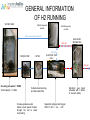
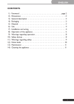
GENERAL INFORMATION
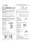
OF H2 RUNNING
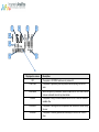
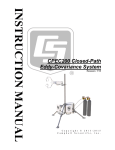
WATER TANK
O2/H20 separator
module
H2/H20 separator
module
Water come back in the tank
H2O+ H2
WATER PUMP
GAS LIQUID
SEPARATOR
H2O+ O2
ELECTROLYSIS
CELL
FILTER
H2O+ H2
Use only pure water > 10MΩ
Tank Capacity : 2.3 liters
Contains deionizer bag
and dust water filter
Increase pressure water
Allows a best speed of water
through the cell to avoid
overheating
Separate hydrogen and Oxygen
2H2O => 4H+ + 4e- + O2
Electronic gas liquid
separator with 2 levels
of sensors safety
Hydrogen generator
ND series
- ND-H2 Purity > 99.9995%
- Pressure up to 10 bar
- Simple dessicant cartridge + Nafion tube
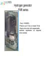
Hydrogen generator
PAR series
- Purity > 99.9999%
-Pressure up to 12 bar, on request 16 bar
-Single column dryer with programmable
automatic regeneration via integrated
clever calendar
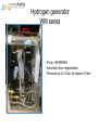
Hydrogen generator
WM series
- Purity >99.99999%
- Automatic dryer regeneration
- Pressure up to 12 bar, on request 16 bar
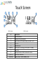
Touch Screen
1
4
5
6
9
8
2
10
3
7
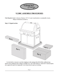
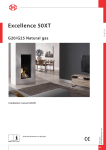
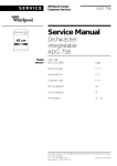
WM.H2 models
#
PAR.H2 models
Description
1
Real outlet pressure
2
Pressure set by user (set-point)
3
System status and Pre-alarms display, see table 1 and 3
4
H2 Flow %
5
Water tank level
6 (WM.H2)
Water quality in percentages (100% GOOD – 0% BAD)
7
Date / Time
8
Touching this label an HELP windows will be shown
9 (PAR.H2)
Internal dryer residual life
10 (PAR.H2)
Quality of water : GOOD, NORMAL, BAD
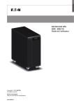
System state
1
4
5
6
8
2
3
7
Displayed on screen
OFF
Description
The system is STOPPED and does not produce H2
STARTING
The system is generating internal pressure before opening the OUTLET
valve
CHECKING
When the system is pressurized, before to open the OUTLET valve, the unit
make an automatic check of any internal leak.
FILLING
The system is filling the line connected ON the OUTLET with the maximum
available flow
WORKING
The system is working and the line pressure has reached the VALUE set by
the user
STANDBY
The system is internally pressurized and ready, but the OUTLET valve is
close
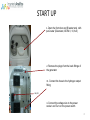
START UP
1- Open the front door and fill water tank with
pure water (Deionized, ASTM II, <0,1uS )
2- Remove the plugs from the back fittings of
the generator
•3- Connect the hose to the hydrogen output
fitting
ON/OFF
4- Connect the voltage wire to the power
socket and Turn on the power switch
8
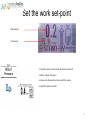
Set the work set-point
Real pressure
Pressure set
1- Touch the screen on the center for at least 2 seconds
2- Select « Adjust Pressure »
3- Increase or decrease the pressure with the arrows.
4- Touch the screen to valid it
9
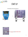
START UP
Touch the blue key or slide your finger right to left
or
Choose START CLOSED or OPEN
10
System status
OFF
Control screen
Description
When the machine is in the OFF state (production stopped) you can give the
START command with subsequent opening of the outlet valve (START/OPEN) or
not (START/CLOSE)
STARTING
WORKING
FILLING
During operation we can give the command to STOP or closure of the outlet
valve
STANDBY
In the STANDBY state can give the command STOP or opening of the outlet
valve
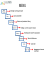
MENU
Change working pressure
User parameter
Alarm and prealarm history
Voltage, current, power values
Working time and H2 produced
Service Submenu
Leak test
Management of internal
water tank
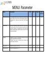
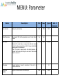
MENU: Parameter
Name
Description
Min
Max
Typical
Unit of
measure
Pressure Drop Delay
If the system cannot bring the H2 pipes up to pressure, after
having waited for the time set in this parameter production is
interrupted with a buzzer and visual alarm (“Out Pressure
error”).
2
10
10
min
Pressure Rise
During the filling stage of pipes connected on the H2 outlet, if
the pressure does not rise with a minimum slope defined by this
parameter, production is interrupted with a buzzer and visual
alarm (“Low Out Press”). When the value is set to 0.0, this
check will be disabled.
0
100
0,3
psi/min
Autostart
"Enabled": when power is restored after a black-out the system
restart and goes into the working mode.
“Disabled”, when power is restored after a black-out, the
system stays in OFF status.
No
Yes
Yes
Pressure Unit
Defines the pressure unit: psi, bar
Psi
Bar
Bar
Temperature Unit
Defines the temperature unit: °F,°C
°C
°F
°C
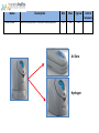
MENU: Parameter
Name
Auto Refill Water
Description
Min
Max
Enables the automatic external tank automatic filling function.
If Enabled when the level of internal water tank go below 5%
the auto fill start and terminate when the level arrive to 95%.
Disabled
Enable
d
Typical
Unit of
measure
Name
ZeroAir Module
Description
Add a Air Zero generator to connect a combine generator
Min
Max
Typical
NO
YES
NO
Air Zero
Hydrogen
Unit of
measure
Name
Hydrogen sensor
Description
Add a external hydrogen sensor
Min
Max
Typical
NO
YES
NO
Unit of
measure
When the customer use
hydrogen as carrier gas, the
only drawback is the danger
of explosion in case of a leak
in the column oven
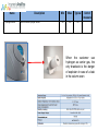
MENU: Parameter
Name
Description
Min
Max
Typical
50%
100%
100%
User flow limit
Allows to restrict the flow
Default Parameter
By selecting YES, all the parameters are set to their default
values
No
Yes
Start Mode
Defines the method used for line pressurization:
Normal: The outlet valve is opened only after the internal
circuit has been pressurized and after having automatically
performed an “internal leak test”
Fast: The valve is opened when the internal pressure is
greater than the set-point set by the user and no "internal leak
test" is carried out
Normal
Fast
Normal
ID Address
Logical address in case of connection of the unit in a
communication bus
1
1
31
Baud Rate
RS485
Speed of communication of the RS485 port
2400
38400
38400
Unit of
measure
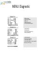
MENU: Diagnostic
- PEM cell voltage
- Peak PEM cell voltage
- PEM current
- PEM cell power supply
- H2 Cell flow produced (cc/min)
- Internal pressure
- External pressure
- Actual H2 Flow produced cc/min
- Water conductibility uS
- Column temperature
- Power Supply temperature
- power supply voltage no. 1
- power supply voltage no. 2 (only models with
flow rates over 400 cc/min)
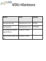
MENU=>Maintenance
Operation
Interval
Spare parts
Change water deioniser bag
4000 working hours or 1 year
SP.H2.DB01
Check the water filter
1000 working hours or 1 year
SP.H2.WFILT.M
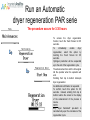
Run an Automatic dryer regeneration
program for PAR serie
As required or 12 months
Change the dessicant cartridge for ND
series
As required or 12 months
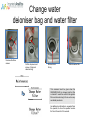
Change water
deioniser bag and water filter
Unscrew the three
screws
Pull the top cover and
remove Oring and
deionizer bag
Remove black
O-ring
Remove water filter
This command must be given when the
DEIONIZER BAG is changed and the filter
is cleared. It resets the counter that registers
filter and deionizer bag's life as well as any
correlated pre-alarms.
An additional confirmation is requested from
the operator; to do so the operator touches
the Touch Screen for 0.5 seconds.
Run an Automatic
dryer regeneration PAR serie
The procedure occurs for 3:30 hours
To access the dryer regeneration
function, touch the Touch Screen for 0.5
seconds.
To
immediately
enable
dryer
regeneration, select this option by
touching the Touch Screen for 0.5
seconds.
Hydrogen production will be suspended
up to the end of the regeneration cycle.
The advancement bar and the time signal
tell the operator when the operation will
end.
Scrolling from top to bottom interrupts
dryer regeneration.
An additional confirmation is requested.
To confirm, touch this option for 0.5
seconds. Instead, scrolling from top to
bottom returns the screen to the display
of the advancement of the process in
course.
NOTE:
any "Dryer Saturated" pre-alarm is
cancelled only upon the conclusion of the
regeneration cycle.
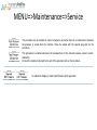
MENU=>Maintenance=>Service
This procedure can be enabled in case of emergency and when there is no instrument to measure
the pressure in output from the machine. Close the output with the special plug and run the
procedure.
This procedure is enabled whenever the measurement of the internal pressure sensors needs
calibration.
Connect the sample instrument to the exit of the generator and run the procedure
To update the display or main board firmware of the generator
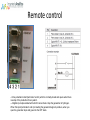
Remote control
- A free potential contact (terminals 1 and 2) which is normally closed and opens when there
is a stop of the production for any alarm.
– A digital input opto-isolated with which it can activate / stop the generation of hydrogen.
When this input (terminals 3 and 4) is feeding the generator begins to produce, when you
open the generator stops and goes into the OFF state.
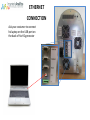
ETHERNET
CONNECTION
Ask your costumer to connect
his laptop on the USB port on
the back of his H2 generator
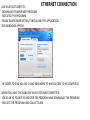
ETHERNET CONNECTION
ASK YOUR COSTUMER TO :
-DOWNLOAD TEAMVIEWER PROGRAM
-EXECUTED THE PROGRAM
-BEGIN TEAMVIEWER WITHOUT INSTALLING THE APPLICATION
THIS WINDOWS APPEAR :
-HE NEEDS TO GIVE YOU HIS ID AND PASSWORD TO HAVE ACCESS TO HIS COMPUTER
WHEN YOU HAVE THE HAND ON YOUR COSTUMER COMPUTER:
-CREAT AN H2 FOLDER TO REGISTER THE PROGRAM AND DOWNLOAD THE PROGRAM
-EXECUTE THE PROGRAM AND COLLECT DATA
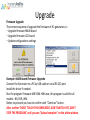
Upgrade
Firmware Upgrade
The correct sequence of upgrade the firmware of H2 generators is :
– Upgrade firmware MAIN board
– Upgrade firmware LCD board
– Update configurations settings
Example: MAIN board Firmware Upgrade
Connect the Generator to a PC by USB cable or serial RS-232 port.
Install the driver if needed.
Run the program Firmware-MB-V504-HW4.exe, this program is valid for all
models : ND, PAR, WM.
Before to proceed you have to confirm with “Continue” button.
After confirm “DON'T TOUCH THE GENERATOR, DON'T SWITCH OFF, DON'T
STOP THE PROGRAM” until you see “Upload complete” on the white window
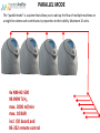
PARALLEL MODE
The “parallel mode“ is a system that allows you to add up the flow of multiple machines on
a single line where each contributes in proportion to their ability. Maximum 10 units.
4x NM-H2-500
99.9999 % H2
max. 2000 ml/min
max. 10 BAR
incl. I/O board and
RS-232 remote control
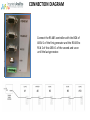
CONNECTION DIAGRAM
Connect the RS-485 controller with the BOX of
485 # 1 of the first generator and the RS 485 to
RS # 2 of this 485 # 1 of the second and so on
until the last generator.
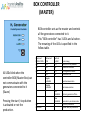
BOX CONTROLLER
(MASTER)
BOX controller acts as the master and controls
all the generators connected to it.
This "BOX controller" has 3 LEDs and a button.
The meaning of the LEDs is specified in the
follow table.
All LEDs blink when the
controller BOX (Master Box) can
not communicate with the
generators connected to it
(Slaves)
Pressing the start / stop button
is activated or not the
production.
Green Led
PRODUCTION
OFF
OFF
OFF
Yellow Led
LINK
OFF
OFF
ON
ON
Red Led
ALARM
OFF
ON
OFF
ON
Regular
FLASHING
Good communication
Random
FLASHING
Bad communication
Fast
FLASHING
Slow
FLASHING
ON
FLASHING
Functionning
Controller is not powered
no device connected
In configuraztion mode
No Master flow
Alarm or generator off line
Generator in pre alarm mode
System in production
system ready for production
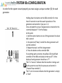
SYSTEM IDs CONFIGURATION
In order for the system to work properly you must assign a unique number (ID) for each
generator.
Holding down the button on the BOX controller for more
than 10 seconds to start the search procedure of the
generators connected to it (see par. 1.2)
Once activated the setup of all generators connected to the
currently displayed "1“ on the display.
At this point
1. hold the center button on one of the generators for about
half a second
2. the system will "beep" and all the other generators will
see the number 2
3. Repeat the step 1 until the last generator
4. Press the button on the controller BOX
If everything works correctly, the yellow LED should flash
controller of the BOX and evenly on the top LEFT of the
display of each generator should see a "P".
The P in "reverse" indicates that the machine is being used
by the system to read the line pressure and control it
("master flow controller")
The P is not in reverse indicates that the generator is simply
a "slave"
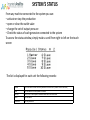
SYSTEM’S STATUS
From any machine connected to the system you can:
– activate or stop the production
– open or close the outlet valve
– change the set of output pressure
– Check the status of each generator connected to the system
To access the status window, simply make a scroll from right to left on the touch
screen
The list is displayed for each unit the following records:
Master
Slave
Out line
Alarm
Pre-Alarm
Unit to be used to read the line pressure and control it (Master flow controller)
Unit connected to the system as a slave
Unit off-line: interrupted communication with the controller
Units on alarm
Units on prealarm
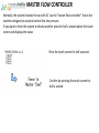
MASTER FLOW CONTROLLER
Normally, the system chooses the car with ID 1 as the "master flow controller" that is the
machine designed to read and control the line pressure.
If you want to force the system to choose another press for half a second about the touch
screen and displays the status
Press the touch screen for half a second
Confirm by pressing the touch screen for
half a second.
Troubleshooting
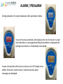
ALARM / PREALARM
During operation, the system executes other automatic checks.
In case of serious anomalies, the display turns red, the buzzer is rapid
and intermittent, a message identifying the problem is displayed and
hydrogen production is immediately interrupted.
In case of anomalies which are not serious, the LDC display turns
yellow, the buzzer sounds every 5 seconds and pre-alarm
messages are displayed.
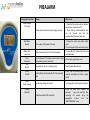
PREALARM
Displayed on screen
Cause
What to do
Temperature of electronic power supply too high
- Check that the system working ambient
temperature is less than 40°C
- Check that the intake/ventilation fans
are not blocked and that the
corresponding filters are clean, see
Poor quality of the water in the tank
- Change the water using better quality
water
- Check the water filter and deioniser bag
Water level less than 5% of the tank capacity
Fill manually the internal tank with new
deionised water
Dryer saturated. This alarm continues until a dryer
regeneration cycle is completed.
Run a dryer regeneration cycle
Internal clock not set or working poorly
Reset system date and time
Failed attempt to automatically fill of internal water
tank
Check that the external water tank is
correctly connected and there is water
inside
Input power voltage not correct
Try turning off and turning on the system.
Water deionization filter saturated
Clean the water filter, replace the
deionizer
bag and reset the filter
remaining life counter using the
appropriate
function
from
the
“MAINTENANCE” menu
Power Supply
T. Too High
Bad Water
Quality
Water Tank
Level Low
Dryer
Saturated
Clock
Not Set
Check
A. Refill
Check
Power Supply
Change
Deionizer
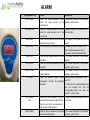
ALARM
Displayed on LCD
Cause
What to do
Low Int.Press.
When the internal pressure cannot
reach the value pre-set by the
manufacturer
Try to restart the system; if the problem
persists, call for service
Low Out Press.
When the external pressure does not
reach the outlet pressure set in the
correct time
Check that the line is connected to the
H2 outlet port
Refill Water
When the internal water tank level goes
below the minimum level
Fill manually the internal tank with new
water
Bad Water Q.
When the quality of the water is too poor
Completely replace the water in the
tank, replace the deionizer bag if
necessary and check the water filter
Hight Cell V.
When the cell voltage exceeds the alarm
threshold
Try to restart the system; if the problem
persists.
Over Current
When the cell current exceeds the alarm
threshold
Try to restart the system; if the problem
persists, call for service
Over Int.Press
When the internal pressure exceeds the
alarm threshold
Try to restart the system; if the problem
persists, call for service
P.S. Temp.
When the electronic power source Check that ambient temperature is less
temperature exceeds the maximum than 35°C
threshold
- Check that the intake/ventilation fans
are not blocked and that the
corresponding filters are clean, see
picture 2 , point 7 and 8
Out Pressure
error
When the outlet pressure remains
lower than the working set-point during
the time set by the user parameter
(during the line filling phase).
Check the connections pipes on the H2
outlet port
Memory data
When an error is detected in the reading
of the saved parameters
Try to restart the system; if the problem
persists, call for service
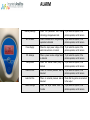
ALARM
Memory damage
When the parameter and alarm Try to restart the system; if the
chronology storage device fails
problem persists, call for service
G.L.S. failure
When a malfunction of the gas-liquid Try to restart the system; if the
separator is detected
problem persists, call for service
Power Supply
When the input power voltage of the Try to restart the system; if the
electronic section is not correct
problem persists, call for service
P.S. damage
When a power source voltage failure Try to restart the system; if the
is detected
problem persists, call for service
Pump failure
When the internal water pump is Try to restart the system; if the
blocked
problem persists, call for service
Leak Int.Pres.
When an internal pressure leak is Try to restart the system; if the
detected
problem persists, call for service
Leak Out Pres.
When an external pressure leak is Check that the gas line is connected
detected
to the output
Heater damage
When the dryer heater does not Try to restart the system; if the
function
problem persists, call for service
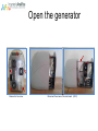
Open the generator
Remove the five screw
Disconnect the screen of the main board (C037)
Main Alarm message
Low internal pressure
Pump failure
High cell voltage
Gas Liquid Separator failed
Power supply failure
Other Alarms
Low internal pressure
Raison:
Not enough pressure
Possible causes:
•Leaks
•Gas Liquid separator valve still open
•Problem with dryer
•Problem with the sensor
•Problem with the cell
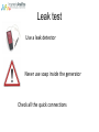
Leak test
Use a leak detector
Never use soap inside the generator
Check all the quick connections
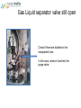
Gas Liquid separator valve still open
Check if there are bubbles in the
transparent tube.
In this case, remove it and test the
purge valve.
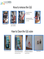
How to remove the GLS
Unscrew the 2 screws
with Allen key
•Diconnect the "black"
•Wire and then remove the
•clear tube,
Disconnect CO35
Disconnect pipes on
quick connections
How to Clean the GLS valve
•Unscrew the central nut
•Unscrew the two screws at
the top left and bottom right
and remove the valve
•Unscrew the two screws at
the top right and bottom left
to open the valve
Clean the valve
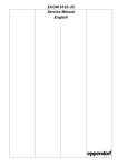
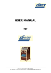
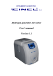
Check the dryer
Regenrating
tube
OUTLET
V1
V2
V1 and V2: Proportionnal Valves
V3 and V4: Inlet valves
V5 and V6: Purge valves
Column
2
Column
1
Equillibrating time: 1200s
Operating time: 10800s
Regenaration ratio: 10%
Silencer
V5
V3
V6
V4
INLET
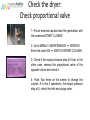
Check the dryer:
Check proportional valve
1- Put an external cap and start the generateur with
the command START CLOSED
2- Go to MENU=> MAINTENANCE => SERVICE
Enter the code 345 => SWITCH DRYER COLUMN
3- Check if the output pressure stay at 0 bar. In the
other case, remove the proportional valve of the
opposite colum and check it
4- Push Two times on the screen to change the
column. If in this 2 operations, the output pressure
stay at 0, check the inlet and purge valve.
Proportionnal valve
Regenrating
tube
OUTLET
V1
V2
Column
2
Example:
Regenration column 1:
V1,V2,V4 and V5 are closed
V3 and V6 is opened
Column
1
The output pressure increase the
valve V2 is opened and damaged
Silencer
V5
V3
V6
V4
INLET
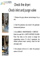
Check the dryer:
Check inlet and purge valve
1- Remove the grey silencer and exchange it by a
cap
2- Start the generator and check if the generator
increase and pressure.
3- Go to MENU=> MAINTENANCE => SERVICE
Enter the code 345 => SWITCH DRYER COLUMN.
Push Two times on the screen to change the
regenerating column. If in this 2 operations, the
internal pressure reach correctly, check the inlet
and purge valve.
If the pressure still be at 0, check the pressure
sensor or the cell.
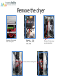
Remove the dryer
Disconnect the terminal
block central green
Disconnect
CO6,
CO14, CO17, CO32,
CO33, CO34
Unscrew the four mounting screws
Disconnect the two pipes
on quick connections
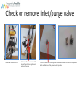
Check or remove inlet/purge valve
Unscrew the central nut
Unscrew the two screws at the
top left and bottom right and r
emove the valve
Then unscrew the remaining two screws and clean the internal components
after verification of the presence of impurities
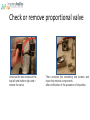
Check or remove proportional valve
Unscrew the two screws at the
top left and bottom right and r
emove the valve
Then unscrew the remaining two screws and
clean the internal components
after verification of the presence of impurities
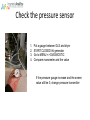
Check the pressure sensor
1.
2.
3.
4.
Put a gauge between GLS and dryer
START CLOSED tht generator
Go to MENU => DIAGNOSTIC
Compare manometer and the value
If the pressure gauge increase and the screen
value still be 0, change pressure transmitter
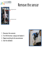
Remove the sensor
External pressure sensor
Internal pressure sensor
1.
2.
3.
4.
Disconnect the connector
Turn left the sensor, unplug it and replace it
Repeat everything for the second sensor
Start the calibration
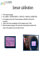
Sensor calibration
1. Put an external gauge
2. Go to MENU => MAINTENANCE => SERVICE => MANUAL CALIBRATION
3. In the display menu select "manual pressure calibration" and start the
procedure
4. Wait for the terms automatically until the pressure reach 10 bar
5. Read the pressure gauge on the exact set on the generator and press the
center of the display to save and exit the menu
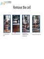
Remove the cell
Unscrew the two screws
on the cables of the cell
power
Remove the two screws below
Disconnect the two
transparent tubes inlet
and outlet water
Disconnect the two white tubes
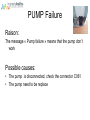
PUMP Failure
Raison:
The message « Pump failure » means that the pump don’t
work
Possible causes:
• The pump is disconnected, check the connector C061
• The pump need to be replace
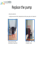
Replace the pump
- Empty the water tank
- Unplug the connector CO61, located at the end of the wires yellow / red / black and
Unscrew the two screws
located below the generator
Disconnect
the
transparent tubes
two
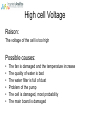
High cell Voltage
Raison:
The voltage of the cell is too high
Possible causes:
•
•
•
•
•
•
The fan is damaged and the temperature increase
The quality of water is bad
The water filter is full of dust
Problem of the pump
The cell is damaged, most probability
The main board is damaged
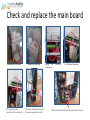
Check and replace the main board
Unscrew the four screws
Disconnect the cable
connection of the cooling fans
Remove the water cap
Disconnect the cables connecting
the power supply and the earth
Unplug
the
central green
connector
Cut the three fixing wires
Disconnect the cable "flat" and the power cords of the cell
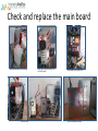
Check and replace the main board
Unscew the four front screws
Pull the rack
Unscrew the five screws on
the rear panel
Disconnect the cable "flat"
Unscrew the sixscrews
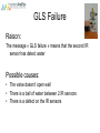
GLS Failure
Raison:
The message « GLS failure » means that the second IR
sensor has detect water
Possible causes:
• The valve doesn’t open well
• There is a ball of water between 2 IR sensors
• There is a defect on the IR sensors
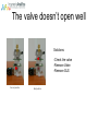
The valve doesn’t open well
Solutions:
-Check the valve
-Remove Valve
-Remove GLS
Correct position
Bad position
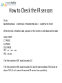
How to Check the IR sensors
Go to:
MAINTENANCE SERVICEPASSWORD 345 COMPLETE TEST
When the test is finished, take a picture of the screen or write down all the data
LEAK TEST:
C1 PASS
C2 PASS
GLS PASS
IR1: xx xxx xxx
IR2: xx xxx
The first number of IR1 must be under 20
The first number of IR2 must be under 30, but the last numbers of IR2 must be
above 100 ( if not, means the second IR sensor has a problem)
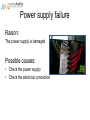
Power supply failure
Raison:
The power supply is damaged
Possible causes:
• Check the power supply
• Check the electrical connection