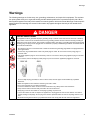
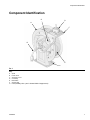
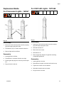
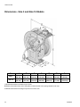
1
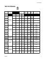
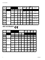
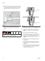
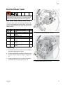
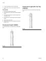
Repair and Parts SD Series™ Cord and Light Reel 3A2826D EN For storing electric cord used to provide electricity and/or light. For indoor and dry location use only. Not approved for use in explosive atmospheres or hazardous locations. Models: pages 3 and 4 X Important Safety Instructions Read all warnings and instructions in this manual and in SD Series Cord and Light Reel Installation manual. Save all instructions. Size 10 Model Size 5 Model Table of Contents Table of Contents 120 Volt Models . . . . . . . . . . . . . . . . . . . . . . . . . . . . 3 230 Volt Models . . . . . . . . . . . . . . . . . . . . . . . . . . . . 4 Warnings . . . . . . . . . . . . . . . . . . . . . . . . . . . . . . . . . 5 Component Identification . . . . . . . . . . . . . . . . . . . . 7 Adjusting Spring Tension . . . . . . . . . . . . . . . . . . 8 Troubleshooting . . . . . . . . . . . . . . . . . . . . . . . . . . . 9 Repair . . . . . . . . . . . . . . . . . . . . . . . . . . . . . . . . . . . 11 Replacing the Spring Cassette . . . . . . . . . . . . . 11 Replacing the Accessory Cord . . . . . . . . . . . . . 12 Electrical Power Cords . . . . . . . . . . . . . . . . . . . 17 Slip Ring Replacement . . . . . . . . . . . . . . . . . . . 19 Single Industrial Receptacle 120V Models . . . . 21 NEMA 5-20R (24N871) . . . . . . . . . . . . . . . . . . . 21 Single Industrial Receptacle 230 Models CEE 7/7 16 Receptacle (24N872) . . . . . . . 21 Fluorescent Light (16N223) . . . . . . . . . . . . . . . 22 Fluorescent Light with Tool Tap (16N224) . . . . 22 LED Light 120V (16N227) . . . . . . . . . . . . . . . . . 22 Tool Tap 120V (16N226) . . . . . . . . . . . . . . . . . 22 Tri-Plug GFCI Industrial Receptacle . . . . . . . . . 24 5-15R (24N880) . . . . . . . . . . . . . . . . . . . . . . . . 24 Replacement Bulbs . . . . . . . . . . . . . . . . . . . . . . 25 For Fluorescent Lights - 16P697 . . . . . . . . . . . . 25 For 230V LED Lights - 16P1696 . . . . . . . . . . . . 25 Parts Size 5 shown . . . . . . . . . . . . . . . . . . . . . . . . . . 27 Size 5 and Size 10 Models . . . . . . . . . . . . . . . . 28 Kits . . . . . . . . . . . . . . . . . . . . . . . . . . . . . . . . . . 30 Technical Data . . . . . . . . . . . . . . . . . . . . . . . . . . . . 34 Dimensions - Size 5 and Size 10 Models . . . . . 35 Graco Standard Warranty . . . . . . . . . . . . . . . . . . . 36 Related Manuals 3A2592 - SD Electric Cord Reel Instructions 3A2828 - Reel Enclosure Installation 406742 - Ball Stop Kit 406743 - Roller Guide Kit 2 3A2826D 120 Volt Models 120 Volt Models Model Description Size Wire Gauge Current (AWG) (Amperes) Blue Cord Length Size 5 24M510 13 16 10 12 20 12 18 16 13 16 13 12 20 12 20 12 18 12 15 12 15 16 0.3 16 0.3 16 0.3 16 10 16 10 16 10 24M511 Cord, No Accessory 24M512 24M513 24M517 24M518 Single Industrial Receptacle 24M521 24M522 24M524 24M525 24M526 Tri-Plug GFCI Industrial Receptacle 24M527 24M528 Fluorescent Light 24M529 24M530 24M531 Fluorescent Light with Tool Tap 24M532 3A2826D Accessory Size 10 16 Power Cord Insulation Connect 50 feet 15 meters SJTOW 95 feet 29 meters SJTOW 50 feet 15 meters SJOOW 95 feet 29 meters SJOOW 35 feet 10 meters SJTOW 50 feet 15 meters SJTOW 35 feet 10 meters SJOOW 50 feet 15 meters SJOOW 95 feet 29 meters SJOOW 50 feet 15 meters 95 feet 29 meters SJOOW SJOOW 35 feet 10 meters SJTOW 50 feet 15 meters SJTOW 95 feet 29 meters SJTOW 35 feet 10 meters SJTOW 50 feet 15 meters SJTOW 95 feet 29 meters SJTOW NEMA 5-15P (24N866) NEMA 5-15P (24N866) NEMA 5-20P (24N868) NEMA 5-20P (24N868) NEMA 5-15P (24N866) NEMA 5-15P (24N866) NEMA 5-20P (24N868) NEMA 5-20P (24N868) NEMA 5-20P (24N868) NEMA 5-15P NEMA 5-15P NEMA 5-15P (24N866) NEMA 5-15P (24N866) NEMA 5-15P (24N866) NEMA 5-15P (24N866) NEMA 5-15P (24N866) NEMA 5-15P (24N866) - - - NEMA 5-15R (24N892) NEMA 5-15R (24N893) NEMA 5-20R (24N871) NEMA 5-20R (24N871) NEMA 5-20R (24N871) Tri-Plug NEMA 5-15R (24N880) Tri-Plug NEMA 5-15R (24N880) 16N223 16N223 16N223 16N224 16N224 16N224 3 230 Volt Models Model Description Size Wire Gauge Current (AWG) (Amperes) Blue 24M533 Cord Length 16 0.05 16 0.05 16 0.05 16 12 16 12 16 10 Size 5 24M534 24M535 24M536 24M537 LED Light with Tool Tap 24M538 Accessory Size 10 LED Light Power Cord Insulation Connect 35 feet 10 meters SJTOW 50 feet 15 meters SJTOW 95 feet 29 meters SJTOW 35 feet 10 meters SJTOW 50 feet 15 meters SJTOW 95 feet 29 meters SJTOW NEMA 5-15P (24N866) NEMA 5-15P (24N866) NEMA 5-15P (24N866) NEMA 5-15P (24N866) NEMA 5-15P (24N866) NEMA 5-15P (24N866) 16N227 16N227 16N227 16N227 - light 16N226 - tool tap 16N227 - light 16N226 - tool tap 16N227 - light 16N226 - tool tap 230 Volt Models Model Description 24M514 24M515 Size Cord, No Accessory 24M516 Size 5 mm2 10 10 meters H05RR-F - - 1,5 mm2 10 15 meters H05RR-F - - - - 1,5 2,5 mm 24M539 Power Cord Insulation Connect Accessory Current (Amperes) Wire Gauge Blue Cord Length 2 16 1,5 mm2 0.05 1,5 mm2 0.05 1,5 mm2 0.05 1,5 mm2 10 1,5 mm2 10 2,5 mm2 16 Size 10 25 meters H07RN-F 10 meters H05RR-F 24M540 LED Light 15 meters H05RR-F 24M541 24M542 24M543 Single Industrial Receptacle 25 meters H05RR-F 10 meters H05RR-F 15 meters H05RR-F 24M544 4 25 meters H07RN-F CEE 7/7 16 A (24N867) CEE 7/7 16 A (24N867) CEE 7/7 16 A (24N867) CEE 7/7 16 A (24N867) CEE 7/7 16 A (24N867) CEE 7/7 16 A (24N869) 16N225 16N225 16N225 CEE 7/7 16 A (24N872) CEE 7/7 16 A (24N872) CEE 7/7 16 A (24N872) 3A2826D Warnings Warnings The following warnings are for the setup, use, grounding, maintenance, and repair of this equipment. The exclamation point symbol alerts you to a general warning and the hazard symbols refer to procedure-specific risks. When these symbols appear in the body of this manual or on warning labels, refer back to these Warnings. Product-specific hazard symbols and warnings not covered in this section may appear throughout the body of this manual where applicable. DANGER ELECTRIC SHOCK HAZARD This equipment must be grounded. Improper grounding setup, or misuse of the cord reel can cause fire or death by electric shock. In the event of an electrical short circuit, grounding reduces the risk of electric shock by providing an escape wire for the electric current. This product is equipped with a cord having a grounding wire with an appropriate grounding plug. The plug must be plugged into an outlet that is properly installed and grounded in accordance with all local codes and ordinances. • This product is for use on a nominal 120V or 230V circuit and has a grounding plug similar to the plugs illustrated in the figure below. • Connect only to grounded electric outlet. Fully insert plug into outlet. Do not connect a three-prong plug to a two-hole outlet. • Fully insert appliance plug into end of accessory cord. Do not connect a three-prong appliance plug to a two hole cord reel. • Do not remove, bend or modify any metal prongs or pins of cord reel or appliances plugged into cord reel. 120V US 230V • Do not modify the plug provided; if it does not fit the outlet, have the proper outlet installed by a qualified electrician. Make sure appliances are off before connecting cord reel to outlet. Do not use excessive force to make connections. Cord reel is marked for indoor use and is to be used indoors only. Always store cord reel indoors. Keep cord reel and accessories away from water. Do not use when wet. Grasp plug to remove from outlet. Do not unplug by pulling on power cord. Look for the number of watts or amperes on appliances to be plugged into cord reel. See label on cord reel for specific wattage or amperage. Do not plug more than the specified number of watts or amperage into this cord reel. • All electrical wiring must be done by a qualified electrician and comply with all local codes and regulations. • • • • • • 3A2826D 5 Warnings FIRE AND EXPLOSION HAZARD When flammable fluids are present in the work area, such as gasoline and windshield wiper fluid, be aware that flammable fumes can ignite or explode. To help prevent fire and explosion: • When installing a cord reel above a hazardous location the reel must be mounted at such a height that the lamp guard cannot reach within 18 inches of the floor. • • • • • • • • Do not plug one cord reel into another. Avoid overheating, do not cover cord reel or accessories with any material. Always unplug cord reel when not in use. Use equipment only in well ventilated area. Eliminate all ignition sources, such as cigarettes and portable electric lamps. Keep work area free of debris, including rags and spilled or open containers of solvent and gasoline. Do not plug or unplug power cords or turn lights on or off when flammable fumes are present. Stop operation immediately if static sparking occurs or you feel a shock. Do not use equipment until you identify and correct the problem. • Keep a working fire extinguisher in the work area. EQUIPMENT MISUSE HAZARD Misuse can cause death or serious injury. • Inspect thoroughly before each use. Do not use if damaged. Replace worn or damaged parts immediately with genuine manufacturer’s replacement parts only. • Do not alter or modify equipment. Alterations or modifications may void agency approvals and create safety hazards. • Make sure cord reel is rated and approved for the environment in which you are using it. • Use equipment only for its intended purpose. Call your distributor for information. • Route power cords and accessory cords away from traffic areas, sharp edges, moving parts, and hot surfaces. Do not run cord through ceilings, walls or floors. • Do not drive, drag or place objects over cord reel cord. • Do not walk on cord. • Do not use cord to pull equipment. • Keep children and animals away from work area. • Comply with all applicable safety regulations. WARNING MOVING PARTS HAZARD Moving parts can pinch, cut or amputate fingers and other body parts. • Keep clear of moving parts. • Do not operate equipment with protective guards or covers removed. 6 3A2826D Component Identification Component Identification G D A F B C E FIG. 1 Key: A B C D E F G Spool Power Cord Accessory Cord Cord Stop Base Plate Support Arm Pawl (cutaway view - part is located behind support arm) 3A2826D 7 Component Identification Adjusting Spring Tension • Never allow reel to spin freely. Doing so could cause serious injury if you are hit by the plug, accessories, or other moving parts. • Reel must be bolted securely in place when making adjustments. Increasing Spring Tension 1. Disconnect cord reel from power source by unplugging power cord from outlet. 2. Pull out accessory cord, 1 to 2 turns and engage pawl. 3. Pull accessory cord back through cord rollers. 4. Wrap a loop of accessory cord onto the spool. See Table 1, Recommended Number of Pre-Turns. 5. Check the spring tension; the accessory cord must pull out fully and retract fully. Wrap more loops, one at a time around the spool until the spring has the desired tension. NOTE: Do not put so many loops onto the reel that the spring winds up tightly before the accessory cord is fully extended. Decreasing Spring Tension 1. Disconnect cord reel from power source by unplugging power cord from outlet. Table 1: Recommended Number of Pre-Turns Model 24M510 24M511 24M512 24M513 24M514 24M515 24M516 24M517 24M518 24M521 24M522 24M524 24M525 24M526 24M527 24M528 24M529 24M530 24M531 24M532 24M533 24M534 24M535 24M536 24M537 24M538 24M539 24M540 24M541 24M542 24M543 24M544 No. of Turns 2 2 3 3 3 2 3 3 2 3 3 3 3 3 3 2 2 3 2 2 3 2 2 3 2 2 3 2 3 3 2 3 2. Pull out accessory cord, 1 to 2 turns and engage pawl. 3. Pull accessory cord back through cord rollers. 4. Remove loops of accessory cord to decrease tension. 5. Check the spring tension. Unwrap more loops, one at a time from the spool until the spring has the desired tension. 8 3A2826D Troubleshooting Troubleshooting Problem Cause Outlet attachment is too heavy Spring lost tension Cord will not retract fully Replace spring. See Replacing Spring Cassette instructions, page 11. Spring is broken Replace spring. See Replacing Spring Cassette, page 11. Spring has lost tension Increase spring tension. See Increasing Spring Tension, page 8. Broken pawl Replace pawl. See instruction manual included with Latch Kit 15Y503. Broken pawl spring Replace pawl spring. See instruction manual included with Latch Kit 15Y503. Pawl not lined up with ratchet plate. See FIG. 13, page 16 for correct operating position. Realign pawl with ratchet plate if not correctly positioned. See Step 17, page 16. Accessory disconnected from cord end Reconnect accessory to output end of accessory cord. Accessory is broken Replace accessory. Wires are not connected Check all connections. Reconnect any loose wires connections. Or replace cord if problem with cord is discovered Worn slip-ring /brushes Replace worn slip-ring/brushes, page 19. Cord is damaged Replace cord. Cord or reel was installed incorrectly Review installation procedures to identify problem. See SD Cord Reel Installation manual. Worn slip-ring /brushes Replace worn slip-ring/brushes, page 19. Slip-ring cover is assembled in the incorrect position Relocate slip-ring cover in correct location, page 19. Reel will not latch Cord reel is not providing adequate ground Cord locked when accessory cord was fully extended 3A2826D Increase spring tension. See Increasing Spring Tension, page 8. Spring is broken Cord will not retract at all No electrical power at the output end of accessory cord Solution 9 Troubleshooting Problem Breaker or fuse trip out (GFCI accessory or European models only) Cord could not extend fully 10 Cause Solution Application does not conform to the electrical rating of the reel Check electrical rating on reel label. Do not attempt to use a reel that is not rated for the application. Wires are broken or shorted Replace all damaged wires. GFCI models only: power was removed from unit Reset GFCI. Spring has too much tension applied Release some of the spring tension. See Decreasing Spring Tension, page 8. 3A2826D Repair Repair Replacing the Spring Cassette the hub (b) must maintain the direction as shown in FIG. 3. a Kits: 24M452, 24M453, 24M454, 24M455, 24M460, 24M462, 24M463 Reference letters used in the following procedure refer to the kit parts table below and Parts page 26. See Parts pages for additional information regarding kits and their related models. Ref 100 Part No. Description KIT, spring cassette b Qty 1 Disassembly 1. Disconnect cord reel from power source by unplugging main supply plug from outlet. FIG. 3 2. Assemble the spring cassette (100) with the hub (32) onto the shaft (7). 7 NOTE: When the spring cassette (100) is assembled into the shaft (7) the surfaces (a and b) must be aligned as shown in FIG. 3. 20 3. For Size 5 models: Replace and tighten the six 10 mm hex nuts (20) 26.6 in-lbs (3 N.m) (FIG. 2). For Size 10 models: Replace and tighten the eight 10 mm hex nuts (20) 26.6 in-lbs (3 N.m) (FIG. 2). 4. Add tension back to reel. See Table 1on page 8. 100 32 5. Plug in cord reel. FIG. 2: Size 10 shown 2. Remove spring tension. See Adjusting Spring Tension/Decreasing, page 8. 3. For Size 5 models: Loosen the six 10 mm hex nuts (20) and remove spring cassette (FIG. 2). For Size 10 models: Loosen the eight 10 mm hex nuts (20) and remove spring cassette (FIG. 2). Reassembly 1. Assemble the hub (32) into the new spring cassette (100) supplied in the kit (FIG. 2). NOTE: The hook of the spring (a) and the hook of 3A2826D 11 Repair Replacing the Accessory Cord 19 17 ELECTRIC SHOCK HAZARD All electrical wiring must be done by a qualified electrician and comply with all local codes and regulations. Kits†: 24N882, 24N885, 24N886, 24N887, 24N888, 24N889, 24N890, 24N891, 24N892, 24N893, 243N894, 24N895, 24N896 Reference letters used in the following procedure refer to the kit parts table below and Parts page 26. See Parts pages for additional information regarding kits and their related models. Ref Part No. 101 † 101a 101b 101c Description KIT, cord replacement, includes CORD, TERMINAL, ring TERMINAL, insulated Qty 1 1 1 1 Disassembly 1. Disconnect cord reel from power source by unplugging main supply plug from outlet. FIG. 4 18 6. Loosen and remove strain relief nut (5) (FIG. 5) to allow power cord to move freely. 2. If the cord reel is enclosed, remove enclosures as necessary to access cord reel. 3. Remove spring tension. See Decreasing Spring Tension, page 8. 4 Never allow the reel to spin freely. Doing so causes the cord reel to spin out of control, which could cause serious injury if you are hit by the plug, accessories or other moving parts 5 4. Remove remaining cord from spool. 5. Remove ball stop from accessory cord end and put all the parts in a safe place to reinstall on the new cord later (FIG. 4). a. Loosen and remove screws (18) and nuts (19). b. Separate two ball stop components (17) to remove from end of accessory cord. 12 FIG. 5 7. While supporting the spool, loosen 34 mm hex nut (4) (FIG. 4). 3A2826D Repair Take special care not to damage power cord when loosening hex nut. A damaged power cord presents a threat of electric shock and a fire hazard. 8. Pull spool assembly away from arm and pedestal. 9. For Size 5 models: Loosen six 10 mm hex nuts (20) and remove cover (36). (FIG. 6). For Size 10 models: Loosen eight 10 mm hex nuts (20) and remove cover (36). (FIG. 6). A Top View 47 36 22 33 20 44 FIG. 7 11. Remove wires from slip ring brush bracket (22) (FIG. 7). 20 FIG. 6: Size 10 shown 10. Loosen three phillips screws (A) on slip ring brush bracket (22) (FIG. 7). 3A2826D 13 Repair LOA D LIN E 47 A FIG. 8 12. For 230V models only disconnect the brown wire (A) from the over current protection device (47). Remove wire from “LOAD” side of device. (FIG. 8) 13. Loosen 10 mm hex nut (20) to relieve tension on cord clamp (33) (FIG. 7). 14. Pull cord back through the grommet (44) in the spool side (FIG. 7). 14 3A2826D Repair Reassembly 1. Route new cord (101a) through grommet (44) and cord clamp (33). Tighten 10 mm hex nut to 6 in-lbs (3 N.m) on cord clamp (33) to hold the cord in place securely (FIG. 7, page 13). 34 NOTE: Ensure there is enough extra cord between cord clamp and slip ring before securing cord clamp (33). 2. For 230V models, attach brown wire to over current protection device. (FIG. 8) 3. Attach wires to slip ring brush bracket (22). Refer to Table 2 to ensure the wires are installed in the correct orientation. (FIG. 9) 4. Attach spool ground wire (W) to slip ring brush bracket (22). Table 2 Grounding (X) (W) Green Green-Yellow 120V 230V Hot (Y) Black Brown Neutral (Z) White Blue 36 20 FIG. 10: Size 10 shown 7. Reassemble cover (36). 8. For Size 5 models: Tighten six 10mm hex nuts (20) to 26.6 in-lbs (3 N.m). For Size10 models: Tighten eight 10mm hex nuts (20) to 26.6 in-lbs (3 N.m). 9. With accessory cord secured to the spool, wrap all the cord around the spool. Wrap cord in a clockwise direction when looking at the spring cassette. (FIG. 11) Z Y W X 22 FIG. 9 5. Tighten to 10.2 in-lbs (1.15 N.m) with phillips screws on slip ring brush bracket (22). 6. Ensure gasket (34) is in place. Refer to FIG. 10 for correct placement. FIG. 11: Size 10 shown 3A2826D 15 Repair 10. Mount spool assembly into arm and pedestal taking care to ensure keyed shaft aligns with arm and pedestal. Ensure washer is in place as shown in FIG. 12. Incorrect washer (8) keyed shaft FIG. 12 11. Tighten 34 mm hex nut (4) to 59 ft-lbs (80 N.m). (Refer to FIG. 5, page 12 for the location of this part.) Correct FIG. 13 12. Check pawl to make sure it is not wedged (FIG. 13). 13. Tighten strain relief nut (5) to 11 ft-lbs (15 N.m). (Refer to FIG. 5, page 12 for the location of this part.) 14. Route accessory cord through roller guide. Take special care not to damage power cord when loosening hex nut. A damaged power cord presents a threat of electric shock and a fire hazard. 15. Position the two ball stop (17) halves around cord. Insert screws (18) through ball stop and hand tighten nuts (19) to hold ball stop in place. (FIG. 4, page 12) 16. Adjust spring tension. See Adjusting Spring Tension, page 8. 17. Install accessory to end of accessory cord. See appropriate section of this manual for accessory installation. 18. If used, reassemble cord reel enclosure following procedure described in the SD Reel Enclosure Installation Instruction manual. 16 3A2826D Repair Electrical Power Cords 21 ELECTRIC SHOCK HAZARD All electrical wiring must be done by a qualified electrician and comply with all local codes and regulations. B Kits: 24N866, 24N867, 24N868, 24N869, 24N870 A Reference letters used in the following procedure refer to the kit parts table below and Parts page 26. See Parts pages for additional information regarding kits and their related models. Ref Part No. 102 102a 102b 102c 102d 102e 102f 102g Description KIT, power cord, includes CORD PLUG (included in 24N868 and 24N869) TERMINAL, ring STOP, cord gland LABEL, safety (only on 120V models) LABEL, safety (only on 120V models) LABEL, safety (only on 120V models) Qty 1 1 1 FIG. 14 4. Cut wire at ring terminals (43). (FIG. 15) 3 1 1 1 1 43 Disassembly 1. Disconnect cord reel from power source by unplugging main supply plug from outlet. 2. Continue disassembly procedure for Replacing the Accessory Cord Instructions, Steps 2 - 9, pages 12 13. 3. Loosen and remove three 7 mm hex nuts (A) and lockwashers (B) from slip ring (21) (FIG. 14). 37 FIG. 15 5. Remove power cord (37). (FIG. 15) 3A2826D 17 Repair Reassembly 1. Route power cord (102a) through strain relief nut (5), cord stop (102d), 34 mm hex nut (4), star washer (27) through pedestal arm, washer (8), and then through shaft (7). (FIG. 16) NOTE: Test each crimp by performing a pull test on each conductor to ensure proper crimp. 4. Mount terminal rings (102c) to appropriate mounting stud as shown in FIG. 18. Refer to Table 3 for wire locations. Table 3 Grounding Hot Neutral 1* 2* 3* 120V Green Black White 230V Green/Yellow Brown Blue 4 2* 5 7 102d 27 102a 1* 8 FIG. 16 102c 2. Orient cord so wires route to appropriate holes and to the left side of the desired mounting stud as shown in FIG. 17 and Table 3. 3* FIG. 18 Left Side 3 1 5. Install three lock washers (B) and three 7 mm hex nuts (A). Tighten nuts to 10.2 in-lbs (1.15 N.m). (FIG. 19) 21 2 A B FIG. 17 3. Use new ring terminals (102c) from kit and crimp onto each conductor of the cord. FIG. 19 18 3A2826D Repair 6. Continue reassembly procedure for Replacing the Cord Instructions, Steps 7 - 18, page 15. Slip Ring Replacement Reference letters used in the following procedure refer to the kit parts table below and Parts page 26. See Parts pages for additional information regarding kits and their related models. Ref Part No. 103 24N687 103a 103b 103c Slip Ring 4. In order to remove slip ring (21), disassembly of spring cassette is required. Remove spring cassette. Continue Disassembly with Steps 1-3 of the Replacing the Spring Cassette section on page 11 of this manual. 5. Remove retaining clip (25). Description Qty KIT, slip ring and brush 1 RING, slip 1 BRACKET, carbon brush 1 TOOL, assembly, repair, slip ring 1 25 7 Disassembly Slip Ring Brush Bracket FIG. 21 6. Slide shaft (7) out of spool. 1. Disconnect cord reel from power source by unplugging main supply plug from outlet. 7. Loosen two set screws (A) and grounding lug on shaft (7). (FIG. 22) 2. Continue disassembly procedure for Replacing the Accessory Cord Instructions, Steps 2 - 13, pages 12 - 13 8. Slide slip ring off of the shaft. 3. Disassemble two 10 mm hex nuts (20) holding slip ring brush bracket (22) to slip ring (21). Remove slip ring brush bracket. (FIG. 20) 1. Insert the slip ring (103a) onto shaft (7) (FIG. 22). Reassembly 103a 21 7 A FIG. 22 20 22 FIG. 20 3A2826D 19 Repair 2. Align set screw holes (A) on shaft (7) with proper holes on new slip ring. Tighten set screw to hand tight. 7. Remove tool (103c) from assembly (FIG. 25). 3. Re-install ground lug and wire between position 1 on slip ring and ground lug on shaft (7). 4. Re-install retaining clip (25) onto shaft (7) and slip ring (103a) in place. (FIG. 21) 5. Press tool (103c) onto the slip ring brush bracket (103b) as shown in FIG. 23. 103c 103b FIG. 25 8. Continue Reassembly with Steps 3 - 18 of the Replacing the Accessory Cord section, beginning on page 15 of this manual. 103c FIG. 23 6. Install slip ring brush bracket (103b) onto spool. Tighten two 10 mm hex nuts (20) to 26.6 in-lbs (3 N.m). 20 103a 103b 103c FIG. 24 20 3A2826D Repair Single Industrial Receptacle b 120V Models NEMA 5-20R (24N871) c B a A FIG. 27: Viewed from the back 5. Slide receptacle into housing. 6. Replace and tighten 3 screws on front of receptacle. FIG. 26 Disassembly 1. Disconnect cord reel from power source by unplugging main supply plug from outlet. 7. Install strain relief and tighten screws. 8. Plug reel back in and test. 230 Models CEE 7/7 16 Receptacle (24N872) 2. Loosen strain relief screws (A) from plug attached to reel. (FIG. 26) 3. Loosen three screws (B) (FIG. 26) on the front of the receptacle. 4. Remove receptacle from housing to expose wiring terminals. 5. Loosen three wiring terminal screws and remove wires. 6. Slide housing over cord. Reassembly 1. If cord is not stripped, strip wire on cord 1/4” (6.35 mm). 2. Place green ground wire in position 1 (a) with green ground screw (FIG. 27). Tighten green screw. 3. Place white wire in position 2 (b) with silver screw (FIG. 27). Tighten silver screw. 4. Place black wire in position 3 (c) with brass screw (FIG. 27). Tighten brass screw. FIG. 28 Disassembly 1. Disconnect cord reel from power source by unplugging main supply plug from outlet. 2. Loosen the phillips screw located in the center of the plug. 3. Pull outer protective shell back to expose wiring terminals. 3A2826D 21 Repair 4. Loosen two phillips screws for strain relief. 5. Loosen three screws to wire terminals. Remove wire. Reassembly 1. Route wire through protective shell. Fluorescent Light with Tool Tap (16N224) For repair instructions, see instructions provided with light. 2. Install brown wire in left wiring terminal and tighten screw. 3. Install green/yellow wire in center wiring terminal and tighten screw. 4. Install blue wire in right wiring terminal and tighten screw. 5. Tighten down strain relief. 6. Slide protective shell over terminals and reinstall phillips screw. Fluorescent Light (16N223) For repair instructions, see instructions provided with light. FIG. 30 FIG. 29 22 3A2826D Repair LED Light 120V (16N227) LED Light 230V (16N225) For repair instructions, see instructions provided with light. For repair instructions, see instructions provided with light. FIG. 31 FIG. 33 Tool Tap 120V (16N226) For repair instructions, see instructions provided with light. FIG. 32 3A2826D 23 Repair Tri-Plug GFCI Industrial Receptacle(24N880) Disassembly Reassembly 1. Disconnect cord reel from power source by unplugging main supply plug from outlet. 1. Route cord through enclosure panel and through opening in roller guide. 2. Loosen two Phillips #2 screws (A) on GFCI cover (B). Remove cover (FIG. 34). 2. Connect green wire from cord to green terminal from GFCI module. Connect black wire from cord to silver terminal. Connect white wire from cord to brass terminal. Re-tighten three Phillips #2 screws (C) (FIG. 35). A 3. Reassemble GFCI cover (B) with two Phillips #2 screws (A) (FIG. 34). B 4. Reconnect power source. 5. Press TEST button to test the GFCI. FIG. 34 3. Unscrew three Phillips #2 screws (C) and disconnect black, white, and green wires from GFCI terminals (FIG. 35). NOTE: Instructions for installing cord reel in enclosure are included in the Hose or Cord and Light Reel Enclosure instruction manual. C C C FIG. 35 24 3A2826D Repair Replacement Bulbs For 230V LED Lights - 16P1696 For Fluorescent Lights - 16P697 A Disassembly Assembly FIG. 36 Disassembly 1. Disconnect cord reel from power source by unplugging main supply plug from outlet. 2. Twist diffuser (A) in a counter clockwise direction. 3. Remove light bulb from diffuser. FIG. 37 Disassembly 1. Disconnect cord reel from power source by unplugging main supply plug from outlet. 2. Slide black handle off. 3. Remove the two screws. 4. Slide diffuser off. Reassembly 1. Install light bulb in diffuser. 5. Remove light bulb. Dispose of light bulb according to applicable guidelines. 2. Twist diffuser in clockwise direction onto light. Reassembly 3. Ensure light bulb plugs into socket by visual inspection. 1. Install light bulb in socket. 4. Plug reel back in and test. 2. Slide diffuser into place over bulb until holes line up. 3. Tighten two screws to secure diffuser. 4. Slide black handle back over handle. 5. Plug reel back in and test. 3A2826D 25 Parts Size 5 shown Parts Size 5 shown 18 20 36 21 34 19 17 16 7 22 13 14 15 28 29 30 31 2 8 3 12 4 9 38 10 5 37 11 41 6 60 25 1 27 24 42 32 20 61 26 35 33 47 3A2826D Parts Size 5 shown Size 5 and Size 10 Models See page 29 for a complete list of kits referenced in the following parts table. REF Kit No. Description Qty BASE, welded, Size 5 models 1 BASE, welded, Size 10 models 1 ARM, guide, Size 5 models 1 ARM, guide, Size 10 models 1 3 NUT, lock 4 4 NUT, M22 x 1.5 MM 1 CAP, wire, M22 x 1.5, 16 AWG, models 24M510, 24M511, 24M514, 24M515, 24M517, 24M518, 24M527 - 24M543 1 CAP, wire, M22 x 1.5, 12 AWG and 2.5 mm2 , models 24M512, 24M513, 24M516, 24M521, 24M522, 24M524, 24N525, 24M526, 24M544 1 STOP, cord, gland, 16 gauge, models 24M510, 24M511, 24M514, 24M515, 24M517, 24M518, 24M527 - 24M543 1 106a 107a 1 106b 107b STOP, cord, gland, 12 gauge, models 24M512, 24M513, 24M516, 24M521, 24M522, 24M524, 24N525, 24M526, 24M544 SHAFT, cord reel, Size 5 models 1 1 2 5 6 7 1 9 105a SPRING, ratchet pawl 1 10 105b BOLT, M10 x 25 lg w patch 1 11 105c BUSHING, pawl 1 12 105d PAWL, ratchet 1 13 108a BRACKET, roller 1 14 108b ROLLER 4 15 108c PIN, roller 4 16 108d SCREW, M6 x 16 4 3A2826D Qty 2 STOP, cord, 12 AWG, 2.5 mm2, models 24M512, 24M513, 24M516, 24M521, 24M522, 24M52424M526, 24M544 2 2 109c STOP, cord, 1.5 mm2, models 24M514, 24M515, 24M539 24M543 18 109b SCREW, machine, pnh 2 19 109a NUT, hex, jam, 2 17 109c NUT, hex, 10 mm, non-metallic insert, Size 5 models 16 NUT, hex, 10 mm, non-metallic insert, Size 10 models 20 21 103a RING, slip 1 22 103b BRACKET, carbon, brush 1 23 SCREW, setting, M5 x10, not shown 2 24 WASHER, flat, spring side 1 25 RING, retaining 1 27 WASHER, with internal teeth 1 100 COVER, spring, black, not shown 1 100 CASSETTE, spring, black, not shown 1 30 100 SPRING, power, not shown, 1 31 100 RIVET, aluminum, 4mm, not shown 4 HUB, cord reel, 3550, Size 5 models 1 HUB, cord reel, 7500, Size 10 models 1 28 WASHER, flat 31 ID Description STOP, cord, 16 AWG, models 24M510, 24M511, 24M517, 24M518, 24M527 - 24M538 109c 20 SHAFT, cord reel, Size 10 models 8 REF Kit No. 29 32 27 Parts Size 5 shown REF Kit No. Qty CLAMP, wire, 12 AWG, 2.5 mm2, models 24M512, 24M513, 24M516, 24M521, 24M522, 24M524, 24N525, 24M526, 24M544 1 106g 107g 1 106h 107h CLAMP, wire, 16 AWG, 1.5 mm2, models 24M510, 24M511, 24M514, 24M515, 24M517, 24M518, 24M527, 24M528, 24M529, 24M530, 24M531, 24M533 24M543 106d SEAL, spool, Size 5 models 1 107d SEAL, spool, Size 10 models 1 FLANGE, set, black, 3550, Size 5 models 1 FLANGE, set, black, 7500, Size 10 models 1 COVER, assembly, slip ring, 3550, models 24M510, 24M512, 24M517, 24M518, 24M521, 24M522, 24M525, 24M527, 24M528, 24M530, 24M531, 24M533, 24M534, 24M536, 24M537 1 COVER, assembly, slip ring, 3550, black, models 24M514, 24M515, 24M539, 24M540, 24M542, 24M543 1 COVER, assembly, slip ring, 7500, metallic blue, 24M511, 24M513, 24M524, 24M526, 24M529, 24M532, 24M535, 24M538 1 COVER, assembly, slip ring, 7500, black, 24M516, 24M541, 24M544 1 33 34 Description 35 36 41 102a CORD, power 1 101a CORD, accessory 1 39 106c 107c PACKING, o-ring, not shown, 1 GROMMET, diaphragm, 12 AWG, 2.5 mm2, not shown, models 24M512, 24M513 24M516, 24M521, 24M522, 24M524, 54M525, 24M526, 24M544 1 GROMMET, diaphragm, 16 AWG, 1.5 mm2, not shown, models 24M510, 24M511, 24M514, 24M4517, 24M518, 24M257, 24M528 - 24M543 1 40 106f 107f 28 Qty 1 PLUG, CEE 7/7, 16A, 230V, model 24M544 1 CORD, grounding with terminals, 12 AWG, models 24M510, 24M512, 24M514, 24M515, 24M517, 24M518, 24M521, 24M522, 24M525, 24M527, 24M528, 24M530, 24M531, 24M533, 24M534, 24M536, 24M537, 24M539, 24M540, 24M542, 24M543 1 CORD, grounding with terminals, 2.5 mm2, models 24M511, 24M513, 24M516, 24M524, 24M526, 24M529, 24M532, 24M535, 24M538, 24M541, 24M544 1 TERMINAL, ring, M4, 16 AWG, 1.5 mm2, not shown, models 24M510, 24M511, 24M517, 24M518, 24M527 - 24M537 6 5 102c* TERMINAL, ring, M4, 16 AWG, 1.5 mm2, not shown, models 24M510, 24M511, 24M514, 24M515, 24M517, 24M518, 24M527 24M541 7 102c* TERMINAL, ring, M4, 12 AWG, 1.5-2.5-4 mm2, M4, not shown, models 24M512, 24M513, 24M516, 24M522, 24M524, 24N525, 24M526, 24M544 102b 42 43 38 Description PLUG, NEMA, 5-20P, 20A, 120V, models 24M512, 25M513, 24M521, 24M522, 24M524, 24N525, 24M526 102b 102c* 37 106e 107e REF Kit No. * Kit 102c contains a quantity of 3. Quantity shown reflects the total number of terminal rings used on assembly. 44 45 46 TERMINAL, insulated, 14-16 AWG, not shown, models 24M514 24M516, 24M539 - 24M544 24N871 SOCKET, single, NEMA, 5-20R, not shown, models 24M521, 24M522, 24M524 CORD, protector-to-carbon brush, not shown, models 24M514 24M516, 24M539 - 24M544 1 1 1 3A2826D Parts Size 5 shown REF Kit No. Description Qty PROTECTOR, thermal, cord reel, 10A, models 24M514 - 24M515, 24M539 - 24M543 1 PROTECTOR, thermal, cord reel, 16A, models 24M516, 24M544 1 TERMINAL, ring M4, 12 AWG and 2.5 mm2, not shown, models 24M510, 24M511, 24M517, 24M518, 24M527 - 24M537 1 TERMINAL, ring M4, 12 AWG and 2.5 mm2, not shown, models 24M514, 24M515, 24M539 24M543 2 50 TERMINAL, ring, M6, 12 AWG, 2 mm2, not shown 1 56 NUT, hex, 10 mm, not-metallic insert 4 60 LABEL, brand 1 61 WASHER 1 47 49 Kits Ref Part No. Description Qty 24M452 KIT, spring casette KIT, spring casette, Size 5 models 24M514, 24M517, 24M527, 24M453 24M533, 24M536, 24M539, 24M542 24M454 62 16P224 TAG, danger, cord reel, English 1 63 16P392 TAG, danger, cord reel, French 1 64 169394 TAG, danger, cord reel, Spanish 1 65 16P454 LABEL, safety, multiple 1 100 KIT, spring casette, Size 5 models 24M512, 24M522, 24M525 KIT, spring casette, Size 5 models 24M510, 24M515, 24M518, 24M455 24M528, 24M531, 24M534, 24M537, 24M540, 24M543 KIT, spring casette, Size 10 mod24M462 els 24M513, 24M516, 24M524, 24M526, 24M544 KIT, spring casette, Size 10 mod24M463 els 24M511, 24M529, 24M532, 24M535, 24M538, 24M541 Replacement Danger and Warning labels, tags, and cards are available at no cost. 3A2826D 29 Parts Size 5 shown Ref 101 Part No. Description Qty 24N882 KIT, cord, 1.5 mm2, 25 M, models 24M541 1 24N885 KIT, cord, 50 feet, 16 AWG, SJTOW, models 24M510, 24M528, 24M531, 24M534, 24M537 1 24N886 KIT, cord, 95 feet, 16 AWG, SJTOW, models 24M511, 24M529, 24M532, 24M535, 24M538 1 24N887 KIT, cord, 50 feet, 12 AWG, SJOOW, models 24M512, 24M522, 24M525 1 24N888 KIT, cord, 95 feet, 12 AWG, SJOOW, models 24M513, 24M524, 24M526 1 24N889 KIT, cord, 1.5 mm2, 10 M, models 24M514, 24M539 1 24N890 KIT, cord, 1.5 mm2, 15 M, models 24M515, 24M540 1 24N891 KIT, cord, 2.5 mm2, 25M, models, 24M516, 24M544 1 24N892 KIT, cord, 35 feet, 16 AWG, SJTOW with NEMA 5-15R, models 24M517 1 24N893 KIT, cord,, 50 feet, 16 AWG, SJTOW with NEMA 5-15R, models 24M518 1 24N894 KIT, cord, 35 feet, 12 AWG, SJOOW, models 24M521 1 24N896 KIT, cord, 35 feet, 16AWG, SJTOW, models 24M527, 24M530, 24M533, 24M536 1 Ref 102 CORD 1 101b TERMINAL, ring 1 101c TERMINAL, insulated 1 24N866 KIT, power cord, NEMA 5-15P, 16 AWG, models 24M510, 24M511, 24M517, 24M518, 24M527 24M538 1 24N867 KIT, power cord, CEE 7/7, 1.5 mm2, models 24M539 - 24M543 1 24N868 KIT, power cord, NEMA, 5-20P, 12 AWG, models 24M512, 24M513, 24M521, 24N522, 24M52424M526 1 24N869 KIT, power cord, CEE 7/7, 2.5 mm2, models 24M516, 24M544 1 24N870 KIT, power cord, 1.5 mm2, models 24M514, 24M515 1 CORD 1 102b PLUG, included in 24N868 and 24N869 1 102c TERMINAL, ring 3 102d STOP, cord gland 1 102e LABEL, safety, only on 120V models 1 102f LABEL, safety, only used on 120V models 1 102g LABEL, safety, only used on 120V models 1 103 24N687 KIT, slip-ring 103a RING, slip 1 103b BRACKET, carbon, brush 1 103c TOOL, assembly, repair, slip ring (not shown) 1 104b 104c 105 24N880 KIT, socket, assembly, GFCI 5-15R SOCKET, Tri-Plug MODULE, GFCI, 125V,15A 1 1 15Y503 KIT, latch, repair 105a SPRING, ratchet pawl 1 105b BOLT, M10 x 25 lg w patch 1 105c BUSHING, pawl 1 105d PAWL, ratchet 1 105e NUT, lock 1 106 30 Qty 102a 104 101a Part No. Description 24N540 KIT, seal and wire clamping, Size-5 3A2826D Parts Size 5 shown Ref Part No. Description 106a 106b 106c 106d STOP, cord, gland, 16 gauge, models 24M510, 24M511, 24M514, 24M515, 24M517, 24M518, 24M527 - 24M543 1 STOP, cord, gland, 12 gauge, models 24M512, 24M513, 24M516, 24M521, 24M522, 24M524 - 24M526, 24M544 1 PACKING, o-ring 1 SEAL, spool, Size 5 models 1 SEAL, spool, Size 10 models 1 106e GROMMET, diaphragm, 12 AWG, 2.5 mm2, models 24M512, 24M513 24M516, 24M521, 24M522, 24M524, 54M525, 24M526, 24M544, 106f GROMMET, diaphragm, 16 AWG, 1.5 mm2, models 24M510, 24M511, 24M514, 24M4517, 24M518, 24M257, 24M528 24M543 1 CLAMP, wire, 16 AWG, 1.5 mm2, models 24M510, 24M511, 24M514, 24M515, 24M517, 24M518, 24M527, 24M528, 24M529, 24M530, 24M531, 24M533 - 24M543 106h 1 107e 1 107f GROMMET, diaphragm, 16 AWG, 1.5 mm2, models 24M510, 24M511, 24M514, 24M4517, 24M518, 24M257, 24M528 24M543 1 107g CLAMP, wire, 12 AWG, 2.5 mm2, models 24M512, 24M513, 24M516, 24M521 - 24M525, 24M526, 24M544 CLAMP, wire, 16 AWG, 1.5 mm2, models 24M510, 24M511, 24M514, 24M515, 24M517, 24M518, 24M527, 24M528, 24M529, 24M530, 24M531, 24M533 - 24M543 1 107h 24N897 KIT, repair, roller bracket 108a BRACKET, roller 1 108b ROLLER 4 108c PIN, roller 4 108d SCREW, M6 x 16 4 222225 KIT, repair, ball stop, 12 AWG and 2.5 mm2 cord 24N538 KIT, repair, ball stop, 1.5 mm2 cord 1 1 107b STOP, cord, gland, 12 gauge, models 24M512, 24M513, 24M516, 24M521, 24M522, 24M524 - 24M526, 24M544 107c PACKING, o-ring 1 SEAL, spool, Size 5 models 1 SEAL, spool, Size 10 models 1 3A2826D Qty 24N539 KIT, repair, ball stop, 16AWG cord STOP, cord, gland, 16 gauge, models 24M510, 24M511, 24M514, 24M515, 24M517, 24M518, 24M527 - 24M543 107d Part No. Description GROMMET, diaphragm, 12 AWG, 2.5 mm2, models 24M512, 24M513 24M516, 24M521, 24M522, 24M524, 54M525, 24M526, 24M544, 109 24N541 KIT, seal and wire clamping, Size-10 107a Ref 108 CLAMP, wire, 12 AWG, 2.5 mm2, models 24M512, 24M513, 24M516, 24M521 - 24M525, 24M526, 24M544 106g 107 Qty 109a NUT, hex 2 109b SCREW, mach. pnh 2 109c BALL STOP 2 24N871 KIT, socket, single, NEMA 5-20R 1 24N872 KIT, socket, single, 16AWG 1 16N226 KIT, tool tap, 125V, 12A 1 16N223 KIT, light, fluorescent, 110V, without tool 1 16N224 KIT, light, fluorescent, 110V with tool 1 31 Parts Size 5 shown Ref 32 Part No. Description Qty 16N225 KIT, light, LED, 110V-240V 1 16N227 KIT, light, LED, Stubby II 1 16P697 KIT, lamp, fluorescent, light, 110V 1 16P696 KIT, lamp, LED, light, 110V-240V 1 16P999 KIT, magnetic clip 1 3A2826D Technical Data Technical Data . Size 5 and Size 10 SD Series™ Cord and Light Reel Voltage Maximum Current Wire Gauge Cord Length Size 5 Size 10 Operating Temperature 24M510-24M518 24M521-24M526 24M542-24M544 24M527-24M541 GFCI Models 24M525 24M526 120V Models 120VAC See Models, page 3 See Models, page 3 230V Models 230VAC See Models, page 4 See Models, page 4 See Models, page 3 and 4 See Models, page 3 and 4 -22°F to 122°F (-30°C to 50°C) -4°F to 104°F (-20°C to 40°C) Complies with UL943 Section 6.7.2.1c requirements for open neutral protection for a portable GFCI. Weight - without accessories 120V Models Size 5: 16AWG, Cord Length - 35 Feet Size 5: 16AWG, Cord Length - 50 Feet Size 10: 16 AWG, Cord Length - 95 Feet Size 5: 12AWG, Cord Length - 35 Feet Size 5: 12AWG, Cord Length - 50 Feet Size 5: 12AWG, Cord Length - 75 Feet Size 10: 12 AWG, Cord Length - 95 Feet 230V Models 25.4 lbs (11.5 kg) 27.6 lbs (12.5 kg) 46.3 lbs (21.0 kg) 28.2 lbs (12.8 kg) 32.0 lbs (14.5 kg) 51.1 lbs (23.2 kg) 51.8 lbs (23.5 kg) 25.6 lbs (11.6 kg) Size 5: 1,5 mm2, Cord Length 10 m Size 5: 1,5 mm , Cord Length 15 m 30.6 lbs (13.9 kg) Size 10: 1,5 mm2, Cord Length 25 m 49.4 lbs (22.4 kg) Size 10: 2,5 mm2, Cord Length 25 m Dimensions Size 5 and Size 10 54.1 lbs (24.5 kg) See page 34 Sound Pressure* Sound Power** 80 dB(A) 87 dB(A) 2 *All readings taken at assumed retraction rate, from assumed operator position. **Sound Power tester per ISO 9614-2. 3A2826D 33 Technical Data Dimensions - Size 5 and Size 10 Models Size Size 5 Size 10 A B 3.5 inches 6.38 inches (89 mm) (162 mm) 3.5 inches 7.5 inches (89 mm) (191 mm) C D E† F G 4.7 inches 7.48 inches 14.8 inches 6.6 inches 13.84 inches (120 mm) (190 mm) (376 mm) (168 mm) (352mm) 4.7 inches 9 inches 19.5 inches 7 inches 17.5 inches (120 mm) (229 mm) (498 mm) (177 mm) (445 mm) † Measurement taken from base to top of bolts. Measurement taken from end of the power cord strain relief to the spring cassette cover cap. Measurement taken from edge of spool to front of the arm. 34 3A2826D Notes Notes 3A2826D 35 Graco SD Series™ Cord and Light Reel Warranty Graco warrants all equipment referenced in this document which is manufactured by Graco and bearing its name to be free from defects in material and workmanship on the date of sale to the original purchaser for use. Graco will, for a period of two (2) years from the date of sale, repair or replace any non-electrical components of the equipment determined by Graco to be defective, and Graco will for a period of one (1) year from the date of sale, repair or replace any electrical components of the equipment determined by Graco to be defective. This warranty applies only when the equipment is installed, operated and maintained in accordance with Graco's written recommendations. This warranty does not cover, and Graco shall not be liable for general wear and tear, or any malfunction, damage or wear caused by faulty installation, misapplication, abrasion, corrosion, inadequate or improper maintenance, negligence, accident, tampering, or substitution of non-Graco component parts. Nor shall Graco be liable for malfunction, damage or wear caused by the incompatibility of Graco equipment with structures, accessories, equipment or materials not supplied by Graco, or the improper design, manufacture, installation, operation or maintenance of structures, accessories, equipment or materials not supplied by Graco. This warranty is conditioned upon the prepaid return of the equipment claimed to be defective to an authorized Graco distributor for verification of the claimed defect. If the claimed defect is verified, Graco will repair or replace free of charge any defective parts. The equipment will be returned to the original purchaser transportation prepaid. If inspection of the equipment does not disclose any defect in material or workmanship, repairs will be made at a reasonable charge, which charges may include the costs of parts, labor, and transportation. THIS WARRANTY IS EXCLUSIVE, AND IS IN LIEU OF ANY OTHER WARRANTIES, EXPRESS OR IMPLIED, INCLUDING BUT NOT LIMITED TO WARRANTY OF MERCHANTABILITY OR WARRANTY OF FITNESS FOR A PARTICULAR PURPOSE. Graco’s sole obligation and buyer’s sole remedy for any breach of warranty shall be as set forth above. The buyer agrees that no other remedy (including, but not limited to, incidental or consequential damages for lost profits, lost sales, injury to person or property, or any other incidental or consequential loss) shall be available. Any action for breach of warranty must be brought within two (2) years of the date of sale. GRACO MAKES NO WARRANTY, AND DISCLAIMS ALL IMPLIED WARRANTIES OF MERCHANTABILITY AND FITNESS FOR A PARTICULAR PURPOSE, IN CONNECTION WITH ACCESSORIES, EQUIPMENT, MATERIALS OR COMPONENTS SOLD BUT NOT MANUFACTURED BY GRACO. These items sold, but not manufactured by Graco (such as electric motors, switches, hose, etc.), are subject to the warranty, if any, of their manufacturer. Graco will provide purchaser with reasonable assistance in making any claim for breach of these warranties. In no event will Graco be liable for indirect, incidental, special or consequential damages resulting from Graco supplying equipment hereunder, or the furnishing, performance, or use of any products or other goods sold hereto, whether due to a breach of contract, breach of warranty, the negligence of Graco, or otherwise. FOR GRACO CANADA CUSTOMERS The Parties acknowledge that they have required that the present document, as well as all documents, notices and legal proceedings entered into, given or instituted pursuant hereto or relating directly or indirectly hereto, be drawn up in English. Les parties reconnaissent avoir convenu que la rédaction du présente document sera en Anglais, ainsi que tous documents, avis et procédures judiciaires exécutés, donnés ou intentés, à la suite de ou en rapport, directement ou indirectement, avec les procédures concernées. Graco Information For the latest information about Graco products, visit www.graco.com. TO PLACE AN ORDER, contact your Graco distributor or call to identify the nearest distributor. Phone: 612-623-6928 or Toll Free: 1-800-533-9655, Fax: 612-378-3590 All written and visual data contained in this document reflects the latest product information available at the time of publication. Graco reserves the right to make changes at any time without notice. For patent information, see www.graco.com/patents. Original instructions. This manual contains English. MM 3A2826 Graco Headquarters: Minneapolis International Offices: Belgium, China, Japan, Korea GRACO INC. AND SUBSIDIARIES • P.O. BOX 1441 • MINNEAPOLIS MN 55440-1441 • USA Copyright 2012, Graco Inc. All Graco manufacturing locations are registered to ISO 9001. www.graco.com Revised September 2014