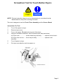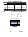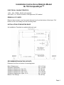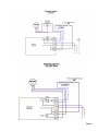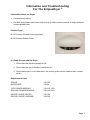
1
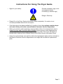
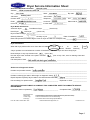
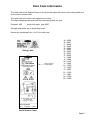
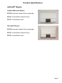
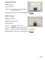
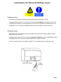
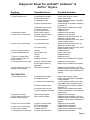
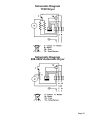
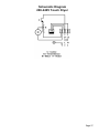
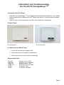
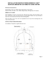
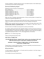
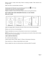
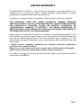
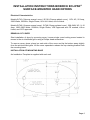
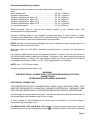
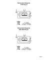
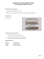
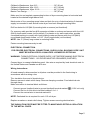
Dryer Troubleshooting and Information Guide Effective 2/08 www.bobrick.com In the United States: BOBRICK WASHROOM EQUIPMENT, INC. 200 Commerce Drive, Clifton Park, NY 12065-1350, Telephone: (518) 877-7444, FAX: 518-877-5029 11611 Hart Street, North Hollywood, CA 91605-5882: (818) 982-9600, FAX: 818-503-1102 100 Bobrick Drive, Jackson, TN 38301-5635, Telephone: (731) 424-7000, FAX: 731-424-7800 In Canada: BOBRICK WASHROOM EQUIPMENT COMPANY. 45 Rolark Drive, Scarborough, Ontario M1R 3B1, Telephone: (416) 298-1611, FAX: 416-298-6351 International Sales: BOBRICK WASHROOM EQUIPMENT, INC. 11611 Hart Street, North Hollywood, CA 91605-5882, 818-764-1000, FAX: 818-503-9941. Australia: Bobrick Washroom Equipment Pty Ltd., 1800-353158, FAX: 1800-221926. United Kingdom: Bobrick Washroom Equipment Ltd., .,+44 (0)20 8366 1771, FAX: +44 (0)20 8363 5794. Germany: 00800 79 00 456, FAX: 00800 79 00 789. Other Countries: +1 (818) 764-1000, FAX: +1 (818)503-9941. Email: [email protected] Page 1 Contents Page 1. Instructions for Using the Dryer Guide 3 2. Sample Dryer Service Information Sheet 4 3. Date Code Information 5 4. Routine Maintenance Instructions 6 Links to model guides: AirCraft®, AirGuard™ & AirPro Dryer™ Compac Dryer™ CubDryer™ EclipseDryer® ElanDryer™ (International Sales Only) Page 2 Instructions For Using The Dryer Guide • Signs for your safety: General mandatory sign (to be accompanied where necessary by another sign) Danger: Electricity Please fill out the Dryer Service Information Sheet completely. If a section is not necessary/available insert N/A in the space. If the faulty dryer has been installed for 2 months or less, then replace complete dryer and return faulty unit to the nearest Bobrick Customer Service Department. When you receive a call concerning a dryer problem inform, the customer/end user to clean the dryer and check the motor brushes before going on with diagnosing the problem. Fax them the cleaning instructions from the guide. If the dryer still does not function after cleaning, then continue filling out the Dryer Service Information Sheet. Inform the customer/end user that the malfunctioning/replaced parts must be returned to the Bobrick Customer Service Department or a charge will be made for replacement parts. Page 3 Dryer Service Information Sheet Distributor/Rep/End-User Name: ______________________________________________________________ Bobrick’s best Address:___________________________________________________________________________________ 12345 Your Street, Suite 100 Toon Town Your State City: _________________________________ State: ______________________ Zip code: ______________ Fantasy Lane Job Name: ____________________________ Job Location: ________________________________________ Contact name: _________________________ Telephone: __________________ Fax: __________________ Email: ________________________________ Account #: __________________ Sales order #: ___________ Invoice #: _____________________________ Invoice Date: ________________ Dryer Model Information: Automatic Dryer: _______ TouchButton Dryer: _______ (check one) Hand Dryer: _____ Hair Dryer: _____ (check one) Dryer model #/voltage: ___________________________________________ Quantity defective: _____________ Quantity on job: _________________ Date of installation: ___________ Date code (as seen on bottom edge of cover on dryer UL label. For example: 04A): ________________________ Dryer Information: When did dryer problems first occur from date of installation? Upon 0–2 Installation Months 2+ Months Out of Warranty ( ) circle one If dryer problem occurred within two months of installation, REPLACE dryer and return faulty dryer. Does the dryer in any way function now? ______ (Yes or No) Has the dryer been cleaned in the past 6 months? ______ (Yes or No) If No, send a cleaning sheet and await outcome. Full description of fault: _______________________________________________________________________ __________________________________________________________________________________________ Reference to Diagnostic Sheets: Problem and possible solution: _________________________________________________________________ __________________________________________________________________________________________ Problem number(s) (as seen in left margin on diagnostic sheet): _______________________________________ Repair kit/parts required (if dryer needs to be returned write RETURN):__________________________________ Part number(s) for replacements: _____________________________ Replaced on SO #: ________________ ANY DEFECTIVE PARTS MUST ACCOMPANY THIS COMPLETED SHEET TO BOBRICK’S SERVICE DEPARTMENT. Information sheet completed by: ______________________________ Branch/Rep Firm: White Copy: Yellow Copy: Pink Copy: Form No. CSD-1196 ST Rev. 2/02 Completion Date: __________________ _________________________________________________________ To Repair/Returns Department at Appropriate Branch (attached to RGA) To BLA Customer Service for Internal Routing To Customer Service Files at Appropriate Branch Bobrick Washroom Equipment, Inc. Printed in U.S.A. Page 4 Date Code Information The date code on all Bobrick Dryers is found on the upper left corner of the rating label and on the serial number label. The date code will contain two digits and one letter. The digits designate the week and the letter designates the year. Example: 48G week forty-eight, year 2007. All digits and letters are in ascending order.. Weeks are numbered from 1 to 52 for each year. Rating Label Date code and serial number H = 2008 G = 2007 F = 2006 E = 2005 D = 2004 C = 2003 B = 2002 A = 2001 Z = 2000 Y = 1999 X = 1998 W = 1997 V = 1996 U = 1995 T = 1994 S = 1993 R = 1992 P = 1991 N = 1990 M = 1989 Serial Number Label Page 5 Routine Maintenance Instructions All Bobrick Dryers require cleaning every 6 months to ensure that they function effectively. Please note that failing to clean the dryer may result in malfunction and can void the warranty. If the dryer is installed in an area prone to dust and dirt this cleaning procedure should be carried out more frequently. Check the length of motor brushes, where applicable, when performing the cleaning procedure. Cleaning Instructions: Warning Risk of electric shock a) Disconnect power supply before removing cover The Exterior of Cover Should be cleaned with a damp cloth, DO NOT use aggressive cleaners or solvents as they may permanently damage the surface. Bobrick dryers are drip proof (IP21 or better, see rating label). DO NOT spray with liquids to an extent that they could enter the unit. b) The Interior Having turned off all power to the dryer, remove the cover. Using a small brush or vacuum, carefully clean out the build up of dust and lint. Check the length of the motor brushes. If less than ½" replace. Check that motor brushes are installed correctly and that brushes are worn evenly. Replace the cover. Turn the power back on. Page 6 ® AirCraft , ™ AirGuard & ™ AirPro Dryer Guide Effective 2/08 www.bobrick.com In the United States: BOBRICK WASHROOM EQUIPMENT, INC. 200 Commerce Drive, Clifton Park, NY 12065-1350, Telephone: (518) 877-7444, FAX: 518-877-5029 11611 Hart Street, North Hollywood, CA 91605-5882: (818) 982-9600, FAX: 818-503-1102 100 Bobrick Drive, Jackson, TN 38301-5635, Telephone: (731) 424-7000, FAX: 731-424-7800 In Canada: BOBRICK WASHROOM EQUIPMENT COMPANY. 45 Rolark Drive, Scarborough, Ontario M1R 3B1, Telephone: (416) 298-1611, FAX: 416-298-6351 International Sales: BOBRICK WASHROOM EQUIPMENT, INC. 11611 Hart Street, North Hollywood, CA 91605-5882, 818-764-1000, FAX: 818-503-9941. Australia: Bobrick Washroom Equipment Pty Ltd., 1800-353158, FAX: 1800-221926. United Kingdom: Bobrick Washroom Equipment Ltd.,+44 (0)20 8366 1771, FAX: +44 (0)20 8363 5794. Germany: 00800 79 00 456, FAX: 00800 79 00 789. Other Countries: +1 (818) 764-1000, FAX: +1 (818)503-9941. Email: [email protected] Page 1 AirCraft®, AirGuard™ & AirPro™ Dryers Contents Page 1. Cover removal 5 2. Diagnostic Sheet 6 3. Field Replacement Parts 9 4. Installation Instructions 12 5. Product Identification 3 6. Schematic Diagrams 26 7. Screwdriver Test 8 8. Warranty 25 Page 2 Product Identification AirCraft® Dryers Surface-Mounted Dryers: B-700 Automatic Hand & Face (pictured) B-701 Touch Button Hand & Face B-731 Touch Button Hair Recessed Dryers: B-750 Automatic Hand & Face (pictured) B-751 Touch Button Hand & Face B-781 Touch Button Hair Page 3 AirGuard™ Dryer B-708 Automatic Series Variations: Series G lower profile cover, no nameplate or printing. (pictured) Not all replacement parts are interchangeable, see parts list. AirPro™ Dryer B-709 Touch Button B-709 Automatic (pictured) Series Variations: Series A Series B Series C touch button model, metal nameplate. automatic model, metal nameplate. automatic model, lower profile cover, no nameplate. Not all replacement parts are interchangeable, see parts list. Page 4 Instructions For Removal Of Dryer Cover Warning Risk of electric shock Disconnect power supply before removing cover To Remove Cover Locate the two tamper resistant screws at the bottom of the dryer cover. Using the Allen-wrench (4 or 5mm), turn the screws clockwise to loosen the cover. Do not take the screws out, the screws have to be moved / rotated up to loosen the cover. Lifting the cover over the two latches at the top of the chassis, remove the cover. To Replace Cover Place the cover over the two latches located at the top of the chassis. Make sure that the cover has a good fit. Using the Allen-wrench, turn the screws counter clockwise moved/ rotated down which will tighten the cover onto the chassis. Do not over tighten screws. Check to make sure the cover has a good fit. Turn power back on to the dryer unit. Page 5 Diagnostic Sheet For AirCraft®, AirGuard™ & AirPro™ Dryers. Problem Possible Cause Possible Solution a) No electricity supply b) Dirty control lens c) Installation fault Check main supply / wiring Clean control lens Check service manual for possible wiring mistakes Check length of brushes; replace if less than ½" Return dryer to Bobrick for repair Replace control Replace triac Replace motor brushes Replace motor brushes Remove white wire from triac; no difference, replace triac Remove white wire from triac; dryer stops, replace control Remove white wire from triac; no difference, replace triac Remove white wire from triac; dryer stops, replace control Replace control Clean control lens Replace control Replace control Return dryer to Bobrick for repairs AUTOMATIC 1. Dryer does not run d) Worn motor brushes 2. Sparks from dryer 3. Dryer runs at low speed e) Element open circuit f) Control nonstart g) Triac open circuit Worn motor brushes a) Worn motor brushes b) Triac halfwave c) Control halfwave 4. Dryer runs continuously a) Triac short circuit b) Control faulty 5. Dryer cycles on and off 6. Dryer sometimes runs 7. Dryer is oversensitive 8. Dryer blows cold air or motor runs fast 9. Grinding noise from dryer 10. Dryer does not run and heating element glows Control Dirty control lens Control Control Heating element a) Worn motor brushes b) Fan cage is bent or damaged Worn motor brushes Replace motor brushes Return dryer to Bobrick for repairs a) No electricity supply b) Installation fault Check main supply / wiring Check service manual for possible wiring mistakes Turn off power, remove cover and bend tabs closer to sensor board Check length of brushes; replace if less than ½" Return dryer to Bobrick for repair Perform Screwdriver Test (see test instructions) Replace motor brushes Replace motor brushes; if still not functioning after replacing the motor brushes, return dryer to Bobrick for repairs. Replace motor brushes Replace timer assembly Replace timer assembly Return dryer to Bobrick for repair Replace motor brushes Replace motor brushes; if still not functioning after replacing the motor brushes, return dryer to Bobrick for repairs. TOUCHBUTTON 1. Dryer does not run c) Tabs are not connecting d) Worn motor brushes e) Element open circuit f) Timer assembly nonstart 2. Sparks from dryer 3. Dryer does not run and heating element glows Worn motor brushes Worn motor brushes 4. Dryer runs at low speed a) Worn motor brushes b) Timer assembly b) Timer assembly Heating element a) Worn motor brushes 5. Dryer runs continuously 6. Dryer blows cold air 7. Grinding noise from dryer Page 6 Problem 8. Dryer is oversensitive and switches on or off randomly 9. Dryer cycles on and off Possible Cause Possible Solution b) Fan cage is bent or damaged a) Button loose Return dryer to Bobrick for repair b) Timer assembly or crystal board Timer assembly or crystal board Perform Screwdriver Test (see test instructions) Perform Screwdriver Test (see test instructions) Pack button O ring with tape Page 7 Screwdriver Test for Touch Button Dryers Warning Risk of electric shock Disconnect power supply before removing cover NOTE: This test instruction sheet is not for dissemination to, and should not be disseminated to, the public including end users. This test is designed to test the Touch Timer Assembly and the Sensor Board. Instructions For Test: 1. Turn off the power to dryer. 2. Remove dryer cover. 3. Turn on the power. Do not touch any part of the dryer. 4. Using an insulated screwdriver, short across the two tabs (see below). a) If dryer runs ...................sensor board may be faulty ......... replace sensor board. b) If dryer does not run ......timer may be faulty ...................... replace touch controller. 5. Turn off power to dryer. 6. Put dryer cover back on and turn power on. Page 8 Field Replacement Parts Replacement parts are intended to be issued by Bobrick after completion of diagnostic sheets and a problem is identified that involves replacement of parts. Replacement parts will then be sold to the customer/rep with credit issued upon the return of identifiable malfunctioning and/or unused parts. A copy of the Dryer Service Information Sheet must be completed by the rep and sent to Bobrick prior to return of parts. Dryer voltage must be identified in order to replace parts. Replacement parts have options for both the 115V and 208–240V dryers. Check voltage and then designate correct part(s). AirCraft® Dryer Replacement Parts AirGuard™ & AirPro™ Dryer Replacement Parts Page 9 AirCraft® Dryer Replacement Parts Surface touch Surface automatic 115V 208-240V Touch controller hand & face 701-360 Touch controller hair Sensor Board 115V 208-240V 701-361 701-360 701-361 731-360 731-361 731-360 731-361 701-138 701-138 701-138 701-138 Automatic controller Air Outlet Grille & Seal Covers 701-120 701-120 115V Recessed touch 208-240V 700-360 700-361 700-120 700-120 701-120 701-120 Recessed automatic 115V 208-240V 750-360 750-361 700-120 700-120 Model code without the B followed by -150, voltage and then color code. Voltage: 115V 208-240V Color codes: Almond Black Grey Ivory White #885 #828 #889 #848 no code Eg. 7007-150 115V #828 Model B7007, voltage 115V, color Black. Common Parts Triac 700-325 Motor Brushes EMD (Red Retainer) 700-101 Motor Brushes Sintech (Brass Retainer) 700-111 Motor Brushes Ametek & Winston 700-121 Cover Mounting Screws 700-156 Allen Wrench 700-55 Wall Box (Recessed Dryers Only) 700-506 Brush identification The following items are not to be field replaced: Motor/fan units. Heating elements. Page 10 AirGuard™ & AirPro™ Dryer Replacement Parts 115V 208-240V Touch controller 701-360 701-361 Sensor Board 701-138 701-138 Automatic controller 700-360 700-361 Air Outlet Grille & Seal 701-120 701-120 B-708 Series A – F cover 708-150 115V 708-150 240V B-708 Series G cover 708G-150 115V 708G-150 240V B-709 Series A cover 709-150 115V 709-150 240V B-709 Series B cover 709B-150 115V 709B-150 240V B-709 Series C cover 709C-150 115V 709C-150 240V Product Identification Common Parts Triac 700-325 Motor Brushes EMD (Red Retainer) 700-101 Motor Brushes Sintech (Brass Retainer) 700-111 Motor Brushes Ametek & Winston 700-121 Cover Mounting Screws 700-156 Allen Wrench 700-55 Brush identification The following items are not to be field replaced: Motor/fan units. Heating elements. Page 11 Installation Instructions Installation Instructions Page Cover Replacement 13 Installation Of Touch Controller 14 Installation Of Base Plate Mounted Triac 15 Installation Of Automatic Controller 16 Instructions For Installation Of Sensor Board 17 Instructions For The Replacement Of Motor Brushes 18 Installation of Surface-Mounted Hand and Hair Dryers 19 ® Installation of Recessed AirCraft Hand and Hair Dryers 22 Page 12 Cover Replacement The dryer covers for different models are NOT interchangeable. Warning Risk of electric shock Disconnect power supply before removing cover Fig 1 Fig 1A Fig 2 Fig 1B Fig 2 Fig 2A To Remove Cover 1. 2. 3. 4. Disconnect the power supply. Locate the two tamper resistant screws at the bottom of the dryer cover. Using the Allen-wrench (4 or 5mm), turn the screws clockwise to loosen the cover. Lifting the cover over the two latches at the top of the chassis, remove the cover. To Replace Cover 1. Place the cover over the two latches located at the top of the chassis. Make sure that the cover has a good fit. 2. Using the Allen-wrench, turn the screws counter clockwise loosening the screws; this will tighten the cover onto the chassis. Do not over tighten the screws. 3. Check to make sure the cover has a good fit. Turn the power supply back on. 4. Allow 10 seconds for the controller to stabilize and check operation of the dryer. On Automatic Dryers if the operation is intermittent check that the controller has a clear view out of the cover aperture, use the spacers provided to raise the controller if required. Page 13 Installation Of Touch Controller To Remove Existing Timer 1. Disconnect the power supply and remove the cover. 2. Remove the timer from the base plate by unscrewing the two screws securing the timer bracket to the base. On recessed dryers the timer bracket is secured to a metal angle bracket, this bracket with its screws must be removed and retained for use on the replacement timer. 3. Disconnect the pink or yellow, red, and black timer wires from the terminal block and the white wire push on connector from the triac (115V only). Place the timer aside for return to the Service Department. To Install New Timer 1. Mount the timer assembly to the base plate . In the case of recessed dryers, it is first necessary to attach the metal angle bracket removed from the faulty timer to the new timer. 2. Route the timer wiring under the element tube and attach the white wire push on connector to the small spade terminal on the triac (115V only), older 208 – 240V units may have a base plate mounted triac, this is no longer required and can be removed. 3. Connect the remaining three timer wires to the terminal block, black wire to terminal 1, red wire to terminal 2, pink wire to terminal 3. 4. Secure wiring with cable ties provided. 5. Replace dryer cover. Switch on electrical supply and test operation. Warning Risk of electric shock Disconnect power supply before removing cover Page 14 Installation Of Base Plate Mounted Triac Note: This procedure applies only to surface-mounted or recessed dryers with triac mounted on the base plate. For touch button models with triac mounted on the timer bracket, the complete timer assembly must be replaced. Warning Risk of electric shock Disconnect power supply before removing cover To Remove Existing Triac 1. Disconnect power supply and remove cover. 2. Remove white, yellow or pink, and black Push On connectors from triac. 3. Remove the two screws securing the triac to the base plate. 4. Remove the triac and place to one side for return to Service Department. To Install New Triac Note: On factory-installed triac, a white Heat sink Compound is interposed between the triac flange and the dryer base plate to ensure rapid conductivity of heat away from the triac. For service purposes this compound is replaced by a thin plastic gasket of heat conducting material, this must be sandwiched between the flange and the base plate during assembly. 1. Position new triac and pad on base plate with the Terminals positioned as shown in illustration below. Insert and tighten the two self-threading screws and shake proof washers provided. 2. Attach the white wire Push On connector to the small spade Terminal on the triac. The black wire from the Terminal Block should then be attached to the next Terminal round in a clockwise direction and the yellow or pink wire to the remaining Terminal. 3. Replace dryer cover. Switch on electrical supply and test operation, allow 10 seconds for the controller to stabilize before placing hands in front of lens (automatic units). Page 15 Installation Of Automatic Controller Warning Risk of electric shock Disconnect power supply before removing cover Older units have an intermediate plug and socket in the wiring, this has now been discontinued and can be removed with the faulty controller. The wiring on older units may be sleeved, this was later replaced by plastic cable ties. Some early 115 volt dryers had 4 way terminal blocks instead of the current 3 way blocks, in these th dryers the wires to the 4 terminal should not be disturbed. To Remove Control Unit 1. Remove outlet grille from front of fan case by unscrewing the securing screws. 2. Remove the screws securing the control unit to the base plate. (Note the different position of recessed and surface-mounted screws). 3. If the control unit wiring is secured by cable ties, carefully cut these to free the 4 wires from other wiring. 4. Remove the Push On Terminal securing the white wire to the triac. 5. Disconnect the controller wires from terminals 1, 2, and 3 on the terminal block. Leave all other wires in position. 6. Carefully lift control out of base plate. Avoid disturbing other wiring. (Note: On recessed dryers it will be necessary to slide the control to the right to clear the fan case). To Install New Control Unit 1. Position the new control unit on the base plate to line up with the screw holes and secure with the screws and washers previously removed. 2. Route wiring under element tube and connect wiring as follows: white wire with Push On Terminal to triac. Black wire to Terminal 1 (with existing black wire). Red wire to Terminal 2 (with existing red wire). Pink wire to Terminal 3 (with existing wiring). 3. Secure all wires to existing wires with a minimum of 2 cable ties. 4. Replace grille and sealing gasket and secure with screws previously removed. 5. Check all wires for security and all screws for tightness. 6. Replace cover. Switch on electric supply. 7. Allow 10 seconds for the controller to stabilize and check operation of the dryer. If the operation is intermittent check that the controller has a clear view out of the cover aperture, use the spacers provided to raise the controller if required. Page 16 Instructions For Installation Of Sensor Board There are two methods fixing sensor boards. 1. Fixed with five screws, Fig 1. 2. Fixed with three screws, Fig 2. Warning Risk of electric shock Disconnect power supply before removing cover Fig 1 In both cases the orientation of the board is critical. Fig 2 1. Switch off mains supply and remove cover. Place cover face downward on a bench using a cloth to protect the finish. 2. Remove the screws securing the board to the collar or bracket. 3. Mount the new board. 4. Replace cover. Switch on electrical supply and carry out normal hand drying procedure to test operation. Page 17 Instructions For The Replacement Of Motor Brushes Warning Risk of electric shock Disconnect power supply before removing cover The brush spares kit contains two brushes. Always replace BOTH brushes. EMD MOTOR To remove the brush: 1. Squeeze the sides of the retainer and ease it over the stud with a small screwdriver. 2. Remove the retainer, cap and brush. Do not mislay the small cap spring. To replace the brush: 1. Insert the new brush into the holder. 2. Place the cap, with the cap spring inside it, over the brush spring and press it over the holder. 3. Slide the retainer down the cap and snap it into position over the stud. SINTECH MOTOR On this motor the brush is replaced by changing the complete brush box assembly. To remove the brush box assembly: 1. Pull the connector off the terminal tab, (A). 2. Depress the retaining tab with a small screwdriver and pull out the brush box, (B) and (C). To replace the brush box assembly: 1. Insert the new brush box and push it down until the retaining tab is level with the slot in the motor end frame. 2. Bend out the retaining tab. 3. Replace the connector on the terminal tab. AMETEK & WINSTON MOTORS On this motor the brush is replaced without disturbing the brush box. To remove the brush: 1. Depress the locking tab in the connector with a small screwdriver, (A). 2. Slide out the connector and remove the brush, (B) and (C). To replace the brush: 1. Insert the new brush into the holder. 2. Press the spring down with a screwdriver until it is below the connector slot, (D). 3. Push the connector into the slot until it locks into position, (E). Make sure that all of the top coil is under the connector. Page 18 INSTALLATION INSTRUCTIONS BOBRICK SURFACEMOUNTED HAND AND HAIR DRYERS ELECTRICAL CHARACTERISTICS. 115V AC, 20 Amp, 50/60 Hz, Single Phase, cULus listed 208–240V AC, 9–10 Amp, 50/60 Hz, Single Phase, cULus listed, VDE approved, CE marked, and CCC approved. REMOVAL OF COVER Start installation of dryer by removing cover. To loosen two cover bolts insert Allen Wrench, provided with dryer, into holes located on bottom of cover on each side of air intake grille. Make sure wrench fits into head of cover bolts and turn CLOCKWISE until bolts stop turning. When cover bolts are screwed in all the way, cover can be removed. To remove cover, place a hand on each side of cover and push up toward top of dryer releasing cover from studs at top of mounting base. Lift cover off mounting base by pulling forward at the bottom and upward at the same time. INSTALLATION OF MOUNTING BASE. An Installation Template is supplied with each unit. RECOMMENDED MOUNTING HEIGHTS. Distance from floor to bottom mounting screw holes of mounting base (Dimension A). Hand dryer. Men’s Washrooms ................................................................. Women’s Washrooms ........................................................... Children’s Washrooms, ages 3-9 .......................................... Children’s Washrooms, ages 9-12 ........................................ Children’s Washrooms, ages 12-15 ...................................... Children’s Washrooms, ages 15-18 ...................................... For Wheelchair Access ......................................................... 46'' (117cm) 44'' (112cm) 32'' (81cm) 36'' (91cm) 40'' (102cm) 44'' (112cm) 38'' (97cm) Page 19 Hair dryer. Men’s Dressing Rooms ......................................................... Women’s Dressing Rooms .................................................... Children’s Dressing Rooms, ages 3-9 ................................... Children’s Dressing Rooms, ages 9-12 ................................. Children’s Dressing Rooms, ages 12-15 ............................... Children’s Dressing Rooms, ages 15-18 ............................... Drill four holes for 1/4" (6.4mm) diameter mounting bolts Bobrick). Fasten mounting base securely to wall. 72'' (183cm) 64'' (163cm) 45'' (114cm) 52'' (132cm) 58'' (147cm) 63'' (160cm) or screws (not furnished by Place mounting base on wall at the desired location of the installed dryer. See recommended mounting heights above. Use the mounting base or the template provided with dryer to mark location of four mounting screw holes and hole for electrical wiring if electrical supply is concealed in wall and will enter dryer from back through mounting base. NOTE: Surface-mounted electrical supply is attached to mounting base in lower right corner. Flange of mounting base and bottom of cover are notched in lower right corner to accommodate connection of electrical conduit. WARNING: TURN ELECTRICAL POWER SUPPLY OFF BEFORE MAKING ELECTRICAL CONNECTIONS. DRYER MUST BE GROUNDED (EARTHED). ELECTRICAL CONNECTION. FOR PROPER ELECTRICAL CONNECTIONS, CHECK LOCAL BUILDING CODE. UNIT MUST BE ISTALLED BY A QUALIFIED LICENSED ELECTRICIAN, WARNING: TURN ELECTRICAL POWER SUPPLY OFF BEFORE MAKING ELECTRICAL CONNENTIONS. Connect dryer to nearest distribution panel. Use wire as required by local electrical code. In the United States and Canada use No. 12 wire or larger. Wiring Instructions: A fused means for disconnection in all poles must be provided in the fixed wiring in accordance with the wiring rules. For 115 Volt Dryers: Connect ground (earthed) wire to ground (earthed) terminal marked , the black or Hot wire to terminal marked L1 and neutral or white wire to terminal marked N. DEDICATED LINE IS REQUIRED FOR EACH 115 VOLT DRYER. For 208–240 Volt Dryers: Connect ground (earthed) wire to ground (earthed) terminal marked and the 208-240 Volt wires to terminals marked L(L1) and N (L2). Secure electrical wire in strain relief clamp provided on mounting base. Page 20 REPLACE COVER. Replace cover by positioning top of cover on studs on top of mounting base and tipping bottom of cover toward wall. Push bottom of cover firmly against wall. NOTE: Space between cover and wall must be the same on four sides. To tighten two cover bolts, insert Allen wrench into holes on bottom of cover. Make sure wrench fits into head of cover bolts and turn COUNTERCLOCKWISE until bolts are tightened. NOTE: Do not over tighten cover bolts; over tightening cover bolts may damage enamel finish. CHECK DRYER OPERATION. To check operation of dryer, follow these instructions: For Touch Button Hair Dryers: Turn electrical power supply on. Touch the chrome-plated touch button once and dryer should turn on. Touch the touch button again after a few seconds and dryer should stop. If left on Hair Dryers will shut off after 80 seconds. For Automatic Hand Dryers: Turn electrical power supply on. Position hands under nozzle and dryer should turn on. Remove hands from under nozzle and dryer should stop. Page 21 INSTALLATION INSTRUCTIONS BOBRICK RECESSED AIRCRAFT® HAND AND HAIR DRYERS ELECTRICAL CHARACTERISTICS. 115V AC, 20 Amp, 50/60 Hz, Single Phase, cULus listed 208–240V AC, 9–10 Amp, 50/60 Hz, Single Phase, cULus listed, VDE approved, CE marked, and CCC approved. INSTALLATION OF RECESSED MOUNTING BOX. An Installation Template is supplied with each unit. RECOMMENDED MOUNTING HEIGHTS. Distance from floor to bottom of framed wall opening (Dimension A). Hand dryer Men’s Washrooms ................................................................. Women’s Washrooms ........................................................... Children’s Washrooms, ages 3-9 .......................................... Children’s Washrooms, ages 9-12 ........................................ Children’s Washrooms, ages 12-15 ...................................... Children’s Washrooms, ages 15-18 ...................................... For the Handicapped ............................................................. 46'' (117cm) 43'' (109cm) 31'' (79cm) 35'' (89cm) 39'' (99cm) 43'' (109cm) 38'' (97cm) Hair dryer Men’s Dressing Rooms ......................................................... Women’s Dressing Rooms .................................................... Children’s Dressing Rooms, ages 3-9 ................................... Children’s Dressing Rooms, ages 9-12 ................................. Children’s Dressing Rooms, ages 12-15 ............................... Children’s Dressing Rooms, ages 15-18 ............................... 73'' (186cm) 64'' (163cm) 46'' (117cm) 53'' (135cm) 59'' (150cm) 64'' (163cm) Page 22 Provide framed opening in wall 13-3/4'' wide x 9-1/2'' high x 3-3/4'' deep (349 x 241 x 95mm) at the desired location of the installed dryer. See recommended mounting heights above. Frame the opening as shown in diagram to support recessed mounting box. Place the recessed mounting box in wall and cut an opening in the framing to allow clearance for electrical conduit and fittings at one of the three conduit knockout locations. Fasten recessed mounting box to framing with minimum of four No. 10 (4.8mm) sheet metal screws (not furnished by Bobrick). Make sure flanges of mounting box are completely flat against finished wall surface. If necessary, use shims or spacers between mounting box and framed wall opening to prevent distortion to box as it is fastened to framing. Install electrical conduit from nearest distribution panel to recessed mounting box. Attach conduit fittings to mounting box. Use wire as required by local electrical code. In the United States and Canada use No. 12 wire or larger. Allow a minimum of 24'' (610mm) of wire to remain in recessed mounting box for connection to dryer terminals. INSTALLATION OF ALUMINUM BASE UNIT INTO RECESSED MOUNTING BOX. Start installation of aluminum base unit into recessed mounting box by removing cover. To loosen two cover bolts, insert Allen wrench, provided with dryer, into holes located on bottom edge of cover. Make sure wrench fits into head of cover bolts and turn CLOCKWISE until bolts stop turning. When both cover bolts are screwed in all the way, cover can be removed. To remove cover, place a hand on each side of cover and push up toward top of dryer releasing cover from studs at top of aluminum base unit. Lift cover off base unit by pulling forward at the bottom and upward at the same time. Insert aluminum base unit into recessed mounting box and fasten to top and bottom flanges of mounting box with the four 1/4-20 UNC (MG-1) screws provided. WARNING: TURN ELECTRICAL POWER SUPPLY OFF BEFORE MAKING ELECTRICAL CONNECTIONS. DRYER MUST BE GROUNDED (EARTHED). ELECTRICAL CONNECTION. FOR PROPER ELECTRICAL CONNECTIONS, CHECK LOCAL BUILDING CODEE. UNIT MUST BE INSTALLED BY A QUALIFIED LICENSED ELECTRICIAN. WARNING: TURN ELECTRICAL POWER SUPPLY OFF BEFORE MAKING ELECTRICAL CONNECTIONS. Wiring Instructions: A fused means for disconnection in all poles must be provided in the fixed wiring in accordance with the wiring rules. For 115 Volt Dryers: Connect ground (earthed) wire to ground (earthed) terminal marked , the black or Hot wire to terminal marked L1 and neutral or white wire to terminal marked N. Page 23 DEDICATED LINE IS REQUIRED FOR EACH 115 VOLT DRYER. For 208–240 Volt Dryers: Connect ground (earthed) wire to ground (earthed) terminal marked and the 208-240 Volt wires to terminals marked L(L1) and N (L2). Make sure excess wire does not interfere with operation of dryer. REPLACE COVER. Replace cover by positioning top of cover on studs on top of aluminum base unit and tipping bottom of cover toward aluminum base. Push bottom of cover firmly against base. NOTE: Space between cover and base must be the same on bottom and both sides. To tighten two cover bolts, insert Allen wrench into holes on bottom edge of cover. Make sure wrench fits into head of cover bolts and turn COUNTERCLOCKWISE until bolts are tightened. NOTE: Do not over tighten cover bolts; over tightening cover bolts may damage enamel finish. CHECK DRYER OPERATION. To check operation of dryer, follow these instructions: For Touch Button Hair Dryers: Turn electrical power on. Touch the chrome-plated touch button once and dryer should turn on. Touch the touch button again after a few seconds and dryer should stop. If left on Hair Dryers will shut off after 80 seconds. For Automatic Hand Dryers: Turn electrical power supply on. Position hands under nozzle and dryer should turn on. Remove hands from under nozzle and dryer should stop. Page 24 LIMITED WARRANTY The Bobrick Dryer and all parts (except motor brushes) are warranted to the original owner of the installed unit for ten years from date of original installation for AirCraft® and AirGuard™ Automatic and Touch Button hand and hair dryers and five years for AirPro™ hand dryers, against defects in factory workmanship or material under normal use and service. * Motor brushes shall be warranted for three years from date of installation. This warranty is limited to repair or exchange of defective parts at the option of Bobrick Washroom Equipment, Inc. THIS WARRANTY DOES NOT COVER ACCIDENTAL DAMAGE, IMPROPER HANDLING OR INSTALLATION, OR REPAIRS MADE BY UNAUTHORIZED PERSONS, AND SPECIFICALLY EXCLUDES CLAIMS FOR INDIRECT, ACCIDENTAL OR CONSEQUENTIAL DAMAGES TO PROPERTY. THE IMPLIED WARRANTIES OF MERCHANTABILITY AND FITNESS FOR A PARTICULAR PURPOSE ARE LIMITED TO THE SAME DURATION OF THE ABOVE WARRANTY. Some states do not allow the exclusion of incidental or consequential damages, so the above limitation or exclusion may not apply to you. Some states do not allow limitations on how long an implied warranty lasts, so the above limitation may not apply to you. This warranty gives you specific legal rights, and you may also have other rights which vary from state to state. * Normal service constitutes performing the following preventive maintenance procedures at six-month intervals. Remove cover and clean any lint, dust or grease from air-intake grille and baffle from behind air-outlet nozzle. Visually inspect motor brushes to insure remaining brush length is a minimum of 1/2 inch (12.7mm). Labor costs for preventive maintenance shall be at owner's expense. For repair or exchange of defective part, send the part, together with installation date and serial number, to BOBRICK. Page 25 Schematic Diagram 115V Dryer Schematic Diagram 208-240V Automatic Dryer Page 26 Schematic Diagram 208-240V Touch Dryer Page 27 CompacDryer Guide TM Effective 2/08 www.bobrick.com In the United States: BOBRICK WASHROOM EQUIPMENT, INC. 200 Commerce Drive, Clifton Park, NY 12065-1350, Telephone: (518) 877-7444, FAX: 518-877-5029 11611 Hart Street, North Hollywood, CA 91605-5882: (818) 982-9600, FAX: 818-503-1102 100 Bobrick Drive, Jackson, TN 38301-5635, Telephone: (731) 424-7000, FAX: 731-424-7800 In Canada: BOBRICK WASHROOM EQUIPMENT COMPANY. 45 Rolark Drive, Scarborough, Ontario M1R 3B1, Telephone: (416) 298-1611, FAX: 416-298-6351 International Sales: BOBRICK WASHROOM EQUIPMENT, INC. 11611 Hart Street, North Hollywood, CA 91605-5882, 818-764-1000, FAX: 818-503-9941. Australia: Bobrick Washroom Equipment Pty Ltd., 1800-353158, FAX: 1800-221926. United Kingdom: Bobrick Washroom Equipment Ltd.,+44 (0)20 8366 1771, FAX: +44 (0)20 8363 5794. Germany: 00800 79 00 456, FAX: 00800 79 00 789. Other Countries: +1 (818) 764-1000, FAX: +1 (818)503-9941. Email: [email protected] Page 1 CompacDryer TM Contents Page 1. Information and Troubleshooting 3 2. Installation Instructions 4 3. Schematic Diagrams 8 4. Series A Cover Installation Instructions 7 5. Warranty 6 Page 2 Information and Troubleshooting For The B-710 CompacDryer TM Information about the Dryer: • • Model B-710 CompacDryer TM is not designed for vandal-prone installations. For vandalprone installations use Bobrick AirCraft® dryers with cast-iron, vitreous enamel finished covers. Only the cover and the electronic controller are available for replacement. Product Types: B-710 Series A B-710 Series B If a Fault Occurs with the Dryer: 1. Check that the electrical supply is OK. 2. Check that the circuit breaker is switched on. 3. Check that sensor is clean and not obstructed. Replacement Parts 710-150 710E-150 710B-150 710BE-150 710360 710361 Series A cover 115V Series A cover 220-240V Series B cover 115V Series B cover 220-240V Controller 115V Controller 220-240V Page 3 Installation Instructions Bobrick Model B-710 CompacDryerTM ELECTRICAL CHARACTERISTICS. 115V , 15A, 1725W , 60 HZ, cULud listed. 220-240V, 7A, 1700W, 50/60Hz, VDE approved, CE marked. REMOVAL OF COVER. Remove three screws, one from each side and one from the bottom of the dryer. Pull bottom of the cover away from the mounting base. INSTALLATION OF MOUNTING BASE. An Installation Template is supplied with each unit. RECOMMENDED MOUNTING HEIGHTS. Distance from floor to bottom of mounting base. Men's Washrooms ....................................................... 46'' (117cm) Women's Washroom ................................................... 44'' (112cm) Children's Washrooms, Age 3-9 ................................... 32'' (81cm) Children's Washrooms, Age 9-12 ................................. 36'' (91cm) Children's Washrooms, Age 12-15 ............................... 40'' (102cm) Children's Washrooms, Ages 15-18 ............................. 44'' (112cm) Barrier-Free Design ...................................................... 38'' (97cm) Page 4 Make sure line on template representing bottom of dryer mounting base is horizontal and located at the desired height above floor. Mark center of four mounting screw holes and hole for entry of electrical wiring if electrical supply is concealed in wall and will enter dryer from back through mounting base. Drill four holes for #10 (M4.8) mounting bolts or screws (not furnished). For masonry walls provide four #10 expansion shields or anchors and secure with four #10 (M4.8) sheet-metal screws (not furnished). For plaster or dry wall construction, provide concealed backing to comply with local building codes and secure with four #10 (M4.8) round-head sheet-metal screws, or 3/16'' (5mm) toggle bolts (not furnished). NOTE: Use 2'' (50mm) long screws in mounting holes. Fasten mounting base securely to wall. ELECTRICAL CONNECTION. FOR PROPER ELECTRICAL CONNECTIONS, CHECK LOCAL BUILDING CODE. UNIT MUST BE INSTALLED BY A QUALIFIED LICENSED ELECTRICIAN. WARNING: TURN ELECTRICAL POWER SUPPLY OFF BEFORE MAKING ELECTRICAL CONNECTIONS. 115V DRYER MUST BE GROUNDED (EARTHED). Connect dryer to nearest distribution panel. Use wire as required by local electrical code. In the United States and Canada use #12 wire. Wiring Instructions: A fused means for disconnection in all poles must be provided in the fixed wiring in accordance with the wiring rules. Trim insulation from end of electrical wire. Remove screws in strain relief clamp. Remove clamping crossbar. Feed electrical wire through clamp. Make connection to terminal block as follows: Connect ground (earthed) wire to ground (earthed) terminal marked Connect the live or Hot wire to terminal marked L or L1. Connect the neutral wire to terminal marked N. . (115V unit only) NOTE: Dedicated line is required for each 115 volt dryer. Replace crossbar on strain relief clamp. Tighten screws securing electrical wire. REPLACE COVER. Replace and tighten three screws, one on each side and one on the bottom to secure cover to mounting base. Page 5 CHECK DRYER OPERATION. Turn electrical power supply on. Position hands under air-outlet, within 4'' (100mm) of the bottom of the dryer. Dryer should turn on. Warm air should blow from air-outlet. Remove hands from under air-outlet and dryer should stop (within 2 seconds). Page 6 LIMITED WARRANTY The Bobrick B-710 CompacDryer TM are warranted to the original owner of the installed unit for one year from date of original installation against defects in factory workmanship or material under normal use and service*. This warranty is limited to repair or exchange of defective parts at the option of Bobrick. This warranty does not cover accidental damage, improper handling or installation, or repairs made by unauthorized persons, and specifically excludes claims for indirect, accidental or consequential damages to property. The implied warranties of merchantability and fitness for a particular purpose are limited to the same duration of the above warranty. Some states do not allow the exclusion of incidental or consequential damages, so the above limitation or exclusion may not apply to you. Some states do not allow limitations on how long an implied warranty lasts, so the above limitation may not apply to you. This warranty gives you specific legal rights, and you may also have other rights which vary from state to state. * Normal service constitutes performing the following preventive maintenance procedures at six-month intervals: Clean any lint, dust or grease from air-intake grille and air-outlet grille. Labor costs for preventive maintenance shall be at owner's expense. For repair or exchange of defective part, send the part together with installation date and serial number to Bobrick. Page 7 Instructions For The Replacement Of The B-710 Series A CompacDryerTM Cover Fig 1 Fig 2 Fig 3 Warning Risk of electric shock Disconnect power supply before removing cover To Remove Existing Cover 1. Remove the (3) Phillips-head screws from the cover, (1) from each side and (1) from the bottom face of the dryer. See Fig. 1. 2. Pull the bottom of the cover outward and slightly downward, then rotate upward to disengage the(2) tabs from the slots at the base. See Fig. 2. To Install New Cover 1. Slide cover onto base plate making sure that the bottom outlet aperture engages in the sides of the outlet grille. 2. Push the top of the cover forward until the (2) tabs snap into the slots in the base. See Fig. 3. 3. Check that the cover is a close fit to the base, then replace the (3) screws. 4. Reconnect electrical supply and test with normal hand drying procedure, allowing 10 seconds for the sensor to stabilize. Page 8 Page 9 CubDryer™ Guide Effective 2/08 www.bobrick.com In the United States: BOBRICK WASHROOM EQUIPMENT, INC. 200 Commerce Drive, Clifton Park, NY 12065-1350, Telephone: (518) 877-7444, FAX: 518-877-5029 11611 Hart Street, North Hollywood, CA 91605-5882: (818) 982-9600, FAX: 818-503-1102 100 Bobrick Drive, Jackson, TN 38301-5635, Telephone: (731) 424-7000, FAX: 731-424-7800 In Canada: BOBRICK WASHROOM EQUIPMENT COMPANY. 45 Rolark Drive, Scarborough, Ontario M1R 3B1, Telephone: (416) 298-1611, FAX: 416-298-6351 International Sales: BOBRICK WASHROOM EQUIPMENT, INC. 11611 Hart Street, North Hollywood, CA 91605-5882, 818-764-1000, FAX: 818-503-9941. Australia: Bobrick Washroom Equipment Pty Ltd., 1800-353158, FAX: 1800-221926. United Kingdom: Bobrick Washroom Equipment Ltd.,+44 (0)20 8366 1771, FAX: +44 (0)20 8363 5794. Germany: 00800 79 00 456, FAX: 00800 79 00 789. Other Countries: +1 (818) 764-1000, FAX: +1 (818)503-9941. Email: [email protected] Page 1 CubDryer™ Contents Page 1. Information and Troubleshooting 3 2. Installation Instructions 4 3. Schematic Diagram 8 4. Warranty 7 Page 2 Information and Troubleshooting For The B-705 CubDryerTM Information about the Dryer: Model B-705 CubTM is not designed for vandal-prone installations. For vandal-prone installations use Bobrick AirCraft® dryers with cast-iron, vitreous enamel finished covers. There are no replacement parts available for this dryer except for the cover. Product Type: B-705 Series A If a Fault Occurs with the Dryer: 1. Check that the electrical supply is OK. 2. Check that the circuit breaker is switched on. 3. Check that sensor is clean and not obstructed, the sensor optics can be cleaned with a cotton swab. Replacement Parts 705-150 705E-150 Series A cover 115V Series A cover 220-240V Page 3 INSTALLATION INSTRUCTIONS BOBRICK CUB™ SURFACE-MOUNTED AUTOMATIC HAND DRYER Electrical Characteristics: Model B-705, 115V, 9A, 1035W, 60HZ, Single Phase, cULus listed. Model B-705E, 220-240V, 6.5A, 1500W, Single Phase, VDE approved, CE marked. REMOVAL OF COVER Start installation of dryer by removing cover. Remove two screws, from the bottom of the dryer. Pull bottom of the cover away from the mounting base. Rotate cover up until tabs on top of the cover release from the top of the mounting base. When the tabs on top of the cover are separated from the top of the mounting base, the cover can be removed. INSTALLATION OF MOUNTING BASE An Installation Template is supplied with each unit. Page 4 Hold the Installation Template against the wall in the desired location of the installed dryer, see following recommended mounting heights. Recommended Mounting Heights: Distance from floor to bottom of mounting base. Men's Washrooms ....................................................... Women's Washroom ................................................... Children's Washrooms, Age 3-9 .................................. Children's Washrooms, Age 9-12 ................................. Children's Washrooms, Age 12-15 ............................... Children's Washrooms, Ages 15-18 ............................ Barrier-Free Design ...................................................... 46-1/2'' (1185mm) 44-1/2'' (1135mm) 32-1/2'' (830mm) 36-1/2'' (930mm) 40-1/2'' (1030mm) 44-1/2'' (1135mm) 38-1/2'' (980mm) Make sure line on template representing bottom of dryer mounting base is horizontal and located at the desired height above floor. Mark center of three mounting screw holes and hole for entry of electrical wiring if electrical supply is concealed in wall and will enter dryer from back through mounting base. NOTE: Surface-mounted electrical supply entry is located in the lower right corner of the mounting base. Bottom of mounting base has an opening in lower right corner to accommodate connection of electrical conduit. Drill three holes for #10 (M4.8) mounting bolts or screws (not furnished). For masonry walls provide three #10 expansion shields or anchors and secure with three #10 (M4.8) sheet-metal screws (not furnished). For plaster or dry wall construction, provide concealed backing to comply with local building codes and secure with three #10 (M4.8) round-head sheet-metal screws, or 3/16'' (5mm) toggle bolts (not furnished). NOTE: Use 1-1/4'' (35mm) long screws. Fasten mounting base securely to wall. ELECTRICAL CONNECTION FOR PROPER ELECTRICAL CONNECTIONS, CHECK LOCAL BUILDING CODE. UNIT MUST BE INSTALLED BY A QUALIFIED LICENSED ELECTRICIAN. WARNING: TURN ELECTRICAL POWER SUPPLY OFF BEFORE MAKING ELECTRICAL CONNECTIONS. Connect dryer to nearest distribution panel. Use wire as required by local electrical code. In the United States and Canada use #12 wire. Wiring Instructions: A fused means for disconnection in all poles must be provided in the fixed wiring in accordance with the wiring rules. Trim insulation from end of electrical wire. Page 5 Remove screws in strain relief clamp. Remove clamping crossbar. Feed electrical wire through clamp. Make connection to terminal block as follows: Connect ground (earth) wire to ground (earth) terminal marked . (115V only) Connect the Live or Hot wire to terminal marked L. Connect the neutral wire to terminal marked N. Replace crossbar on strain relief clamp. Tighten screws securing electrical wire. NOTE: DEDICATED LINE IS REQUIRED FOR EACH 115 VOLT DRYER. REPLACE COVER Align and engage tabs on underside of the top of the cover and top of mounting base. Rotate cover over front of mounting base. Replace and tighten two screws on the bottom to secure cover to mounting base. NOTE: Four sides of cover overlap the mounting base and should be flush with the sides, top and bottom of the mounting base. CHECK DRYER OPERATION Turn electrical power supply on. Position hands under air-outlet, within 4'' (100mm) of the bottom of the dryer. Dryer should turn on. Warm air should blow from air-outlet. Remove hands from under air-outlet and dryer should stop (within 2 seconds). Page 6 LIMITED WARRANTY The Bobrick B-705 CubDryer™ and all parts are warranted to the original owner of the installed unit for one year from date of original installation against defects in factory workmanship or material under normal use and service * . This warranty is limited to repair or exchange of defective parts at the option of Bobrick. THIS WARRANTY DOES NOT COVER ACCIDENTAL DAMAGE, IMPROPER HANDLING OR INSTALLATION, OR REPAIRS MADE BY UNAUTHORIZED PERSONS, AND SPECIFICALLY EXCLUDES CLAIMS FOR INDIRECT, ACCIDENTAL OR CONSEQUENTIAL DAMAGES TO PROPERTY. THE IMPLIED WARRANTIES OF MERCHANTABILITY AND FITNESS FOR A PARTICULAR PURPOSE ARE LIMITED TO THE SAME DURATION OF THE ABOVE WARRANTY. Some states do not allow the exclusion of incidental or consequential damages, so the above limitation or exclusion may not apply to you. Some states do not allow limitations on how long an implied warranty lasts, so the above limitation may not apply to you. This warranty gives you specific legal rights, and you may also have other rights which vary from state to state. * Normal service constitutes performing the following preventive maintenance procedures at six-month intervals. Remove cover and clean any lint, dust or grease from air-intake and air-outlet grille. Labor costs for preventive maintenance shall be at owner's expense. For repair or exchange of defective part, send the part together with installation date and serial number to BOBRICK. Page 7 Page 8 ® EclipseDryer Guide Effective 2/08 www.bobrick.com In the United States: BOBRICK WASHROOM EQUIPMENT, INC. 200 Commerce Drive, Clifton Park, NY 12065-1350, Telephone: (518) 877-7444, FAX: 518-877-5029 11611 Hart Street, North Hollywood, CA 91605-5882: (818) 982-9600, FAX: 818-503-1102 100 Bobrick Drive, Jackson, TN 38301-5635, Telephone: (731) 424-7000, FAX: 731-424-7800 In Canada: BOBRICK WASHROOM EQUIPMENT COMPANY. 45 Rolark Drive, Scarborough, Ontario M1R 3B1, Telephone: (416) 298-1611, FAX: 416-298-6351 International Sales: BOBRICK WASHROOM EQUIPMENT, INC. 11611 Hart Street, North Hollywood, CA 91605-5882, 818-764-1000, FAX: 818-503-9941. Australia: Bobrick Washroom Equipment Pty Ltd., 1800-353158, FAX: 1800-221926. United Kingdom: Bobrick Washroom Equipment Ltd.,+44 (0)20 8366 1771, FAX: +44 (0)20 8363 5794. Germany: 00800 79 00 456, FAX: 00800 79 00 789. Other Countries: +1 (818) 764-1000, FAX: +1 (818)503-9941. Email: [email protected] Page 1 EclipseDryer® Contents Page 1. Information and Troubleshooting 3 2. Installation Instructions 4 3. Schematic Diagrams 8 4. Warranty 7 Page 2 Information and Troubleshooting For The EclipseDryer ® Information about the Dryer: Contemporary styling Durable, deep drawn steel cover with choice of white vitreous enamel or bright polished chrome plated finish Product Type: B-740 Vitreous Enamel Cover (pictured). B-748 Chrome Plated Cover. If a Fault Occurs with the Dryer: 1. Check that the electrical supply is OK. 2. Check that the circuit breaker is switched on. 3. Check that sensor is not obstructed, the sensor optics can be cleaned with a cotton swab. Replacement Parts GRILLE BACKPLATE 740-120 740-25 115V POWER MODULE 208-240V POWER MODULE 740-110 115V 740-110 240V DRYER COVER (WHITE) DRYER COVER (CHROME) 740-150 748-150 Page 3 INSTALLATION INSTRUCTIONS BOBRICK ECLIPSE® SURFACE-MOUNTED HAND DRYERS Electrical Characteristics: Models B-740 (Vitreous enamel cover), B-748 (Chrome-plated cover), 115V AC, 20 Amp, 2300 Watts, 50/60Hz, Single Phase; UL/c-UL Listed; cULus Listed. Models B-740 (Vitreous enamel cover), B-748 (Chrome-plated cover), 208–240V AC, 9–10 Amp, 1900–2400 Watts, 50/60Hz, Single Phase; VDE Approved and CE marked, cULus Listed, and CCC approved. REMOVAL OF COVER Start installation of dryer by removing cover. Loosen single cover-locking screw located in recess in the air inlet/outlet grille using a Phillips-head screwdriver. To remove cover, place a hand on each side of the cover and tip the bottom away slightly from the air inlet/outlet grille. Lift the cover upwards to release the top retaining bracket from the mounting base. INSTALLATION OF MOUNTING BASE An Installation Template is supplied with each unit. Page 4 Recommended Mounting Heights: Distance from floor to bottom mounting screw holes of mounting base. Men's Washrooms ....................................................... 45-1/4'' (1150mm) Women's Washrooms .................................................. 43-1/4'' (1100mm) Children's Washrooms, ages 3-9 ................................ 31-1/4'' (795mm) Children's Washrooms, ages 9-12 .............................. 35-1/4'' (895mm) Children's Washrooms, ages 12-15 ............................ 39-1/4'' (995mm) Children's Washrooms, ages 15-18 ............................ 43-1/4'' (1100mm) For the Handicapped ................................................... 37-1/4'' (945mm) Place mounting base on wall at the desired location of the installed dryer. See recommended mounting heights. Use the mounting base or the template provided with dryer to mark location of three mounting screw holes and access hole for electrical wiring (if electrical supply is concealed in wall and will enter dryer from back through mounting base). NOTE: Surface mounted electrical supply (line cord) is attached to dryer through hole in air inlet/outlet grille in lower left corner. Drill three holes for #10 (M4.8) diameter mounting bolts or screws (not furnished by Bobrick). For masonry walls provide three #10 expansion shields or anchors, then secure with three #10 (M4.8) sheet-metal screws (not furnished). For plaster or dry wall construction, provide concealed backing to comply with local building codes and secure with three #10 (M4.8) round-head sheet-metal screws, or 3/16'' (5mm) toggle bolts (not furnished). NOTE: Use 1-3/4'' (45mm) screws. Fasten mounting base securely to wall. WARNING: TURN ELECTRICAL POWER SUPPLY OFF BEFORE MAKING ELECTRICAL CONNECTIONS. DRYER MUST BE GROUNDED (EARTHED). ELECTRICAL CONNECTION FOR PROPER ELECTRICAL CONNECTIONS, CHECK LOCAL BUILDING CODE. UNIT MUST BE INSTALLED BY A QUALIFIED LICENSED ELECTRICIAN. WARNING; TURN ELECTRICAL POWER SUPPLY OFF BEFORE MAKING ELECTRICAL CONNENTIONS. Connect dryer to nearest distribution panel. Use wire as required by local electrical code. In the United States and Canada use #12 wire or larger. A fused means for disconnection in all poles must be provided in the fixed wiring in accordance with the wiring rules. For Model B-740 115V and B-748 115V Dryers: Connect ground (earth) wire to ground (earth) terminal on the mounting base marked . Connect the black or Hot wire to terminal Page 5 marked L and the white or neutral wire to terminal marked N on the connector block. DEDICATED LINE IS REQUIRED FOR EACH 115-VOLT DRYER. For Model B-740 208–240V and B-748 208–240V Dryers: Connect ground (earth) wire to ground (earth) terminal on the mounting base marked , the Live or Hot wire to the terminal marked L (L1) and the Neutral wire to the terminal marked N on the connector block. Secure electrical wire in strain relief clamp provided on mounting base. REPLACE COVER Replace cover by positioning the top retaining bracket at top rear edge of cover, behind the back of mounting base. Tilt cover downwards and over flange on air inlet/outlet grille. Ensure that the rubber strip is in place between the cover and the grille. NOTE: Space between cover and wall must be the same on both sides. Tighten the single cover-locking screw located in recess in the air inlet/outlet grille. CHECK DRYER OPERATION Turn electrical supply on. Position hands under air-outlet opening and dryer should turn on. Remove hands from under air-outlet opening and dryer should stop. Page 6 LIMITED WARRANTY The Bobrick B-740 & B-748 EclipseDryer® and all parts (except motor brushes) are warranted to the original owner of the installed unit for ten years from date of original installation, against defects in factory workmanship or material under normal use and service *. Motor brushes shall be warranted for three years from date of installation. This warranty is limited to repair or exchange of defective parts at the option of Bobrick Washroom Equipment, Inc. THIS WARRANTY DOES NOT COVER ACCIDENTAL DAMAGE, IMPROPER HANDLING OR INSTALLATION, OR REPAIRS MADE BY UNAUTHORIZED PERSONS, AND SPECIFICALLY EXCLUDES CLAIMS FOR INDIRECT, ACCIDENTAL OR CONSEQUENTIAL DAMAGES TO PROPERTY. THE IMPLIED WARRANTIES OF MERCHANTABILITY AND FITNESS FOR A PARTICULAR PURPOSE ARE LIMITED TO THE SAME DURATION OF THE ABOVE WARRANTY. Some states do not allow the exclusion of incidental or consequential damages, so the above limitation or exclusion may not apply to you. Some states do not allow limitations on how long an implied warranty lasts, so the above limitation may not apply to you. This warranty gives you specific legal rights, and you may also have other rights which vary from state to state. * Normal service constitutes performing the following preventative maintenance procedures at six-month intervals. Remove cover and clean any lint, dust or grease from air inlet/outlet grille. Visually inspect motor brushes to ensure remaining brush length is a minimum of 1/2-inch (13mm). Labor costs for preventative maintenance shall be at owner’s expense. For repair or exchange of defective part, send the part, together with installation date and serial number, to BOBRICK. Page 7 Schematic Diagram 115V Dryer Schematic Diagram 208-240V Dryer Page 8 ™ Elan Dryer Guide International Sales Only Effective 2/08 www.bobrick.com In the United States: BOBRICK WASHROOM EQUIPMENT, INC. 200 Commerce Drive, Clifton Park, NY 12065-1350, Telephone: (518) 877-7444, FAX: 518-877-5029 11611 Hart Street, North Hollywood, CA 91605-5882: (818) 982-9600, FAX: 818-503-1102 100 Bobrick Drive, Jackson, TN 38301-5635, Telephone: (731) 424-7000, FAX: 731-424-7800 In Canada: BOBRICK WASHROOM EQUIPMENT COMPANY. 45 Rolark Drive, Scarborough, Ontario M1R 3B1, Telephone: (416) 298-1611, FAX: 416-298-6351 International Sales: BOBRICK WASHROOM EQUIPMENT, INC. 11611 Hart Street, North Hollywood, CA 91605-5882, 818-764-1000, FAX: 818-503-9941. Australia: Bobrick Washroom Equipment Pty Ltd., 1800-353158, FAX: 1800-221926. United Kingdom: Bobrick Washroom Equipment Ltd.,+44 (0)20 8366 1771, FAX: +44 (0)20 8363 5794. Germany: 00800 79 00 456, FAX: 00800 79 00 789. Other Countries: +1 (818) 764-1000, FAX: +1 (818)503-9941. Email: [email protected] Page 1 Elan™ Dryer Contents Page 1. Information 3 2. Installation Instructions 4 3. Schematic Diagrams 8 4. Warranty 7 Page 2 Information and Troubleshooting For The B-715 Elan™ Dryer Information about the Dryer: • Durable, brushed stainless steel cover. • Only the cover and the electronic controller are available for replacement. Product Types: B-715 Series A If a Fault Occurs with the Dryer: 1. Check that the electrical supply is OK. 2. Check that the circuit breaker is switched on. 3. Check that sensor is clean and not obstructed. Replacement Parts 715-150 715E-150 710360 710361 Cover 115V Cover 220-240V Controller 115V Controller 220-240V Page 3 Installation Instructions Bobrick Model B-715 Elan™ Dryer ELECTRICAL CHARACTERISTICS. 115V , 15A, 1725W , 60 HZ, cULus listed. 220-240V, 7A, 1500-1700W, 50/60Hz, VDE approved and CE marked. B-715E is not available in the United States or Canada. REMOVAL OF COVER. Remove three screws, one from each side and one from the bottom of the dryer. Pull bottom of the cover away from the mounting base. INSTALLATION OF MOUNTING BASE. An Installation Template is supplied with each unit. RECOMMENDED MOUNTING HEIGHTS. Distance from floor to bottom of mounting base. Men's Washrooms ....................................................... 46'' (117cm) Women's Washroom ................................................... 44'' (112cm) Children's Washrooms, Age 3-9 ................................... 32'' (81cm) Page 4 Children's Washrooms, Age 9-12 ................................. 36'' (91cm) Children's Washrooms, Age 12-15 ............................... 40'' (102cm) Children's Washrooms, Ages 15-18 ............................. 44'' (112cm) Barrier-Free Design ...................................................... 38'' (97cm) Make sure line on template representing bottom of dryer mounting base is horizontal and located at the desired height above floor. Mark center of four mounting screw holes and hole for entry of electrical wiring if electrical supply is concealed in wall and will enter dryer from back through mounting base. Drill four holes for #10 (M4.8) mounting bolts or screws (not furnished). For masonry walls provide four #10 expansion shields or anchors and secure with four #10 (M4.8) sheet-metal screws (not furnished). For plaster or dry wall construction, provide concealed backing to comply with local building codes and secure with four #10 (M4.8) round-head sheet-metal screws, or 3/16'' (5mm) toggle bolts (not furnished). NOTE: Use 2'' (50mm) long screws in mounting holes. Fasten mounting base securely to wall. ELECTRICAL CONNECTION. FOR PROPER ELECTRICAL CONNECTIONS, CHECK LOCAL BUILDING CODE. UNIT MUST BE INSTALLED BY A QUALIFIED LICENSED ELECTRICIAN. WARNING: TURN ELECTRICAL POWER SUPPLY OFF BEFORE MAKING ELECTRICAL CONNECTIONS. 115V DRYER MUST BE GROUNDED (EARTHED). Connect dryer to nearest distribution panel. Use wire as required by local electrical code. In the United States and Canada use #12 wire. Wiring Instructions: A fused means for disconnection in all poles must be provided in the fixed wiring in accordance with the wiring rules. Trim insulation from end of electrical wire. Remove screws in strain relief clamp. Remove clamping crossbar. Feed electrical wire through clamp. Make connection to terminal block as follows: Connect ground (earthed) wire to ground (earthed) terminal marked Connect the live or Hot wire to terminal marked L or L1. Connect the neutral wire to terminal marked N. . (115V unit only) NOTE: Dedicated line is required for each 115 volt dryer. Replace crossbar on strain relief clamp. Tighten screws securing electrical wire. THE INSULATION PIECE MUST BE FITTED TO MAINTAIN ELECTRICAL ISOLATION TO THE METAL COVER. Page 5 REPLACE COVER. Replace and tighten three screws, one on each side and one on the bottom to secure cover to mounting base. CHECK DRYER OPERATION. Turn electrical power supply on. Position hands under air-outlet, within 4'' (100mm) of the bottom of the dryer. Dryer should turn on. Warm air should blow from air-outlet. Remove hands from under air-outlet and dryer should stop (within 2 seconds). Page 6 LIMITED WARRANTY The Bobrick B-715 Elan™ Dryer are warranted to the original owner of the installed unit for five years from date of original installation against defects in factory workmanship or material under normal use and service*. This warranty is limited to repair or exchange of defective parts at the option of Bobrick. This warranty does not cover accidental damage, improper handling or installation, or repairs made by unauthorized persons, and specifically excludes claims for indirect, accidental or consequential damages to property. The implied warranties of merchantability and fitness for a particular purpose are limited to the same duration of the above warranty. Some states do not allow the exclusion of incidental or consequential damages, so the above limitation or exclusion may not apply to you. Some states do not allow limitations on how long an implied warranty lasts, so the above limitation may not apply to you. This warranty gives you specific legal rights, and you may also have other rights which vary from state to state. * Normal service constitutes performing the following preventive maintenance procedures at six-month intervals: Clean any lint, dust or grease from air-intake grille and air-outlet grille. Labor costs for preventive maintenance shall be at owner's expense. For repair or exchange of defective part, send the part together with installation date and serial number to Bobrick. Page 7 Page 8