1
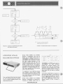
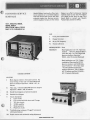
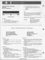
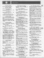
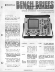
F
T-PACKAn3
MARCH-APRIL 1977
E 1N USE
instrument Po uae s
twdbits. *
Ttw HP 50WA Signamre Analyzer is a
ian's tool for field troubleshootiryl
ocess0r-W intehrmts-down
But in the programmed digital world, service sCtrema&s are devoid of waveform
voltage and other service E
for
all
the not very comforting
bit strearm look pretty much alike 0rr an
oscill
The pro\lrdem is com
with microprocessors,
controtlers. for a m
with them there is n
association between
particular sections
example, if a k
fumtion fails in an
product, a service manual might
checking the int&gr&d circuits that mtrbt that function. With microprocessors,
on the other hand, key debouncing is
more likely a timeshared function, tying
up the whole processor for a brief
moment. When it fails, any one of a large
number-of IC's could be faulty.
.
analysis. It has been learned that although
the microprocessor has simplified instrument design, it has complicated troublend. However, when
stream is faulty the technician can trace it
baek through gates and memory elements
until he isolates an element with correct
us85 an annotsad
re 2 for an example)
*
voltages and wave-
int at which circuit operafrom there t r a d s
failed comwnent
in
The signature analyzer is a troubleshooting tool desigrred qmciP&ly for microprocessor-based- products. More inetruments that are rn'wopracesor based will
be inboduced this year than the sum of
all computer systems installed to date.
Microprocessors are relatively low in cost
and easy to design around. But, they are
just as complex and diffkuk to repair as
computers because of time-reja
Industry predicts that ten m
will fail in the field this year,
them in microprocessor produ
will cost one to two billion
repairs. Thus, the signature analyzer
promises to have a significant i
OR
m n t wviwems.
WWW. HPARCHIVE.COM
without the use of specid extender
cost actually fell and th
time amounted to appr
the overall development
goal of wrviceabidity
now has about 40
IN THIS ISSUE
SIGNATURE ANALYSIS
SERVICE TRAINING
SEMINARS
3476AB PRODUCT
IMPROVEMENT
SAFETY SERVICE NOTES
NEW SER VICE NOTES
s
DESIGNING IN SIGNATURE
ANALYSIS
THE OPERATING AND SERVICE
MANUAL
Besides the design engineer, the writer of
the service manual made an important
contribution to the successful application
of the signature analysis to the 3455A
Voltmeter. The service manual is written
in such a way that a technician, unfamiliar with the signature analyzer can
walk up to a defective voltmeter, read the
instructions and within a short time
locate the fault. One element in the
manual is a troubleshooting flow chart
(see Figure 3) that systematically guides
the technician through the fault finding
process.
The initial tests may or may not rely on
signature analysis. They allow isolation of
the fault down to a specific area. Diap
nostic programs cannot carry on from
here, since they do not have access to
individual nodes, but it is from here on
down to the components t h a t signature
analysis excels.
At t h i s level the repair man uses the
annotated schematics and graphs of board
layouts together with the flow chart, to
find the bad node. A node is defined as a
terminal of any branch of a network, or a
terminal common to two or more
branches. Also called junction point,
vertex or nodal point. In some cases the
manual indudes instructions as to which
IC to replace. In other cases the use of a
logic probe, which is an integral part of
the logic tracer may be required. A
current sensor, such as the HP 547A,
helps to find short circuits between traces
or to ground and is particularly helpful
when bus problems are encountered.
The 3455A Service Manual shows
pictures of the board and defines the set
up for each test (see Figure 3). Each
picture shows only the signatures related
to the particular test directing the
technician's effort toward the important
areas on the board. The ROM prugram
even simulates interrupt signals, ensuring
however, that they occur predictably at
the same spot within a window so that
stable signatures result.
The siwature analyzer has its own self
check. Each test set up is tested by
touching the power supply voltage with
the instrument's probe to input a
sequence of all one's. If this characteristic
signature is correct the setup conditions
and framing of the measurement window
are verified. Specifically, this tells the
user that the switches on the signature
analyzer, as vel1 as all the jumpers,
switches and control buttons in front and
rear of the voltmeter are correctly s e t
This means the confidence level of the
user is very high at the start of a test.
A portion. of the circuits read-onlymemory - perhaps 5% - must contain a
special program for stimulating the
various nodes in the circuits. The stimulation serves more to excite or force a state
change on the nodes, than to generate
meaningful data. Frequently this stimulus
program may be merged with the
products performaneverification program. The correct signatures are
developed by simply exercising the
various parts of a circuit that i s known to
be good and noting the results on the
circuit diagram.
A second requirement is to break feedback paths within the circuit, either by
using hardware switches, jumpers or
connectors, or by disabling gates with
software. This requirement is necessary to
prevent a fault from being fed back
around and disturbing all data nod?.
When these two requirements are met,
back tracing a fault to its source is a
straight forward process of tracing faulty
signatures.
WHAT'S A SIGNATURE?
In using signature analysis t h e procedure
varies slightly, depending on whether the
fault lies in the kernel (the minimum configuration of microprocessor and ROM
necessary to run the simplest test progam) or in the outlying circuitry.
Everything depends on the signature. A
kind of compressed "fingerprint" of the
data present on a node, it is compared
with the correct signature printed on the
schematic of the product so that any
discrepancy may be noted and traced to
the source. The signature is derived
through linear-fedback shift registers.
which generate pseudo-random binary
sequences. For signature analysis, bit
sequences being measured are summed in
modulo 2 with the register feedback. The
register is clocked by the same clock as
the bit stream under measurement. Input
sequences may be any length, but a t the
end of the measurement, only the residue
remaining in the register is looked a t
These 16 bits, when displayed in a 4 digit
format, comprise the signature of the
m u r e d bit stream. Figure 4 shows a
simplified block diagram of this concept.
If the fault is in the outlying circuitry (a
keyboard or display scanner, input/
output latch, etc.) the technician simply
switches the circuit to the diagnostic
mode. Then, guided by the manual, he
uses the test instrument to trace faults
back to their source. But what if the
problem lies in the kernel, and even the
ROM stimulus program will not run?
Here, the microprocessor itself can provide a stimulus if its address counter is
allowed to sequence through the address
field. To do t h i s it is only necessary to
open the datarfnstruction bus and force
the no-operation instruction onto it. This
stimulus program checks out all the
address lines and the individually enabled
ROMs as well. All of these nodes are
readily characterized with signatures.
WWW.HPARCHIVE.COM
a
a
SIGNATURE ANALYSIS
.Since signature analysis relies on the
ability of an instrument to control itself
in a synchronous manner, asynchronous
circuits, like monostables djrect-memwyaccess, dynamic memory, or interrupts,
need to be carefully controlled.
Generally, simple provisions in the hardware can be made to force them into a
synchronous or disabled condition when
that is required for a particular test.
In summary, HP expects the Signature
Analyzer to have a significant impact on
our own in-house service costs. True,
there are some design costs to be
accounted for in the new products utilizing signature analysis. However, in the
long run, these coots will be more than
offset by the serviceability of the instrument. And, as of today Signature
Analysis i s the first new and workable
concept for servicing microprocessor
based instruments.
BUFFER
VAL10
MEMORY
ADDRESS
FIGURE 1. Exampb of Block Di.anrn with Sfpatufa
PARCH IVE.CO M
I., :I
.-•
*I
I
U
ALU. A1 U28
r
SIGNATURE ANALYSIS
=-a
Loutlon
AlW1
Pin 2
Pin5
fin9
Pin 12
Smture
acpu
UPVH
I
2131
HAF7
m k The Signatures At
The Following Points
~ o b c l o n Stgnature
AlV29
Pm2
Rn5
UCHS
87C2
Pin 7
Fin10
HHFS
HO74
'Check l h s Swpaturn At
The Follovrtng Points.
U
Loutton
AlU25
Stenmure
ATTENTION 3476A/B
MULTIMETER OWNERS
NOTE: The output of a multiplbinputaxduriubOR
gmnra b w e h that Ute b t s a t d trmids.
Inputs and output am to zero modulo 2.
Service Notes 3476A-3 and 34768-2
describe a modification that may be
desired for all 3476A's serials prior to
1619A05840 and 34768's serials prior to
1617A05610. This modification increases
the input voltage protection of the
ohmmeter circuits from 30 volts rms
(where the 32 milliamperes fuse, F2, now
Mows) to 160 volts rms. This modification should help in the Case of accidental
applkatjon of voltage between the voltohm input terminals and COM terminal
when in the ohms function.
To determine if your 3476 has already
been modified, examine A1 R2. If A1 R2
is a 5 kilohm resistor the modificationhas
been made. Otherwise, make the changes
as described in Table 1.
Two new Service Notes have been issued
for your multimeter that show modifications to improve OHMS protection and
operating performance.
Service Notes 3476A-4 and 34768-3
describe a modification to improve performance on 3476A's serials prior to
WWW. H PARCHIVE.COM
1619A05840 and 34768's serials prior to
1617AO5610. The 3476 sometimes
exhibits the overload condition (five
horizontal bars) with the instantaneous
application of about loo0 volts dc or 700
volts rms. A gradual increase in voltage to
these values will not cause an overload
indication.
In the event a 3476A fails to respond to a
step input, R51 which is in series with pin
6 of U1 should be changed from -hp part
number 0683-1035 (10 kilohm, 5%) to
part number 0683-1025 (1 kilohm, 5%).
General location of R51 is shown in
Figure 1.
I
CUSTOMER SERVICE SEMINARS
smmms
axwr~dvepmduct line. Seminars are ptaviLd throughout Europe and the United
to bring wc tr*q
ottt 8rm. Fer re$mP
form on p i q e 16 of
Bench &kWsor contact your MawlsttPackard sale0 and Service Office.
141T, 8552A/B, 85538,
85548,8555A
SPECTRUM ANALYZERS
MAY 9-12, PARAMUS, NJ
LAB
1.
Front panel familiarization
11. Change fmt mixer
111. Set up YIC frequency
IV. N o d calibration
PREREQUISITES -None
-Read Application text 150, “Spectrum
PRESTUDY
Analysis . . .Spectrum Analyzer Basics”;
View video tape “141T/8552B/8554B
Spectrum Analyzer Operation”,
90030-646,20 minutes (optional)*
-Read Application text 136, “Understanding and Operating the 85 5 5 A
Spectrum Analyzer and 8445B Automatic Preselector”; View video tapes
“141T/8552B/8555A Spectrum
Analyzer Operation”, Part I, 90030647,28 minutes and Part 11,90030697,18 minutes (Optional)
COURSE CONTENT
LECTURE
I.
II.
III.
IV.
V.
VI.
Vu
Block diagram related to front panel controls. Op
tional viewing of video tape “141T/8552B/8553B
Spectrum Analyzer Operation”, 90030-607,26
minutes.
Video tape, “141T/8552B/8554B Spectrum Analyzer
Operation”, 90030-646,20 minutes
0ved block diagram and system description
Detailed block diagram
Circuit descriptions
A. Inputcircuits
B.
First, second and third mixers and IF stages
C.
YIGdrivecircuits
D. 50MHzasnpwler
E. Marker generator
F. Pbase-lmk ~ircuits
Troubleshootingtechniques (“bugged” instruments
with typical failures)
Rtpak cautions and xaechanical tuning adjustmentg
WWW.HPARCHIVE.COM
*’
* I
:I
CUSTOMER SERVICE SEMINARS
3040A NETWORK ANALYZER
JULY 18-20, LOVELAND, CO
AND
3042A NETWORK ANALYZER
JULY 18-22, LOVELAND, CO
3050B DATA ACQUISITION SYSTEM
JULY 11-14 (3-1/2 DAYS), LOVELAND, CO
9‘
MOTE: 3042A insuocrtion same as 3040A plus two additional days (July 21-22)
COURSE CONTENT
COURSE CONTENT
LECTURE
I.
11.
LECTURE AND LAB
I.
Introduction To Low Frequency Network Analysis
3495AScanner
A. Operation
B. Theory of Operation
C. Troubleshooting
3490A Multimeter
A. Operation
B. Guarding
C. Theory of Operation
D. Troubleshooting
111. Hewlett-Pa
IV. WculatorC
II.
3330B Synthesizer
A. Operation and Specifications
B. Theory of Operation
1.
Block Diagram of Amplitude Section
2.
B l d IXqatm of Frequezkcy S e c ~ o n
3. Raferen
ency Sixtion
c.
of HP-fB
LAB
uniquecircuitry
1. +NLoops
L o @ W c Amplitude Control by Refer2.
ence Frequency
thmic State Machines
The lecture is given in a lab environment.
PRESTUDY
lator and Tondensed Description of
the Hewlett-Packard Interface Bus”.
-3595A, 3490A, 59405A Manuals, Interface Bus User’s Guide, and Condensed
Description of the Hewlett-Packard
Interface Bus.
Section
E. Repair and Calibration
F. Service Literature and
111. 3570A Network Analyzer
A. Operation and Specification$
B. Theory of Operation
1. Block Diagram of Amplitude Section
Hock Diagram of Digital Section
2.
C.
Calibration and Adjustments
(Specid Emphasis on Crystal Filter Adjustment)
WWW. H PARCHIVE.COM
I
CUSTOMER SEK VICE SEMINARS
"
0
D.
IV.
V.
€
Troubleshooting
1.
Troubleshootingthe Measurement
Channels
2.
Troubleshootingthe Digital Channels
E. Service Literature and Service Kits
Hewlett-PackardInterface Bus
A.
Description
B. Interfacing
3042A System
A. Basic System Concepts
B.
System Operation
C.
System Performance
D. Controllers
E. Programming
F. Interfacing
G. System Troubleshooting
H. System Service Kits and Service Literature
8640 AM/FM SIGNAL GENERATOR
8660 SYNTHESIZED SIGNAL GENERATOR
435/436 POWER METERS
8480 SENSOR AND 11683A CALIBRATOR
AUG 29-SEPT 2, PAL0 ALTO, CA
PREREQUISITES -should have read the Interface
Bus User's Guide for the appropriate calculator and the Condensed Description of the
Hewlett-PackardInterface Bus.
Must also be able to operate and
program the appropriate
calculator.
-Interface Bus User's Guide and
PRESTUDY
Condensed Description of
Hewlett-PackardInterface Bus.
Also 3330B and 3570A Manuals.
. "
b
12 3 9 5 6 7 5 9
a
WWW. H PARCHIVE.COM
I :: i 0 i 11
CUSTOMERSERVICESEMINARS
V.
fnstrumentFiow
VI. optrons
c1
The lecture is given in a lab environment
voltage and waveshape measurements at
during the lecture. A famihiation wit
cedwes is also includec'
PREREQUISITES - h i e knowledge
OverallBlockDia
I.
PRESTUDY
Numedd Eminpb of Frequency Megsuzemen
III. Input Phiwe Lock Loop Circuit Ilex
11.
INTRODUCING MODERN
DIGITAL TECHNOLOGY
AND TROUBLESHOOTING
TO THE ANALOG REPAIRMAN
-April 1973 HP J O W ~d w ~ b b g
534ok "The F u n h n a of
PAC1FICA HOTEL
6161 Centinela Blvd.
;
THIRD DAY
0
0
0
0
IC Techno1 : DCTL, RTL, DTL, CTL, TTL, ECL, EECL,
HTL,MOS,IO?! L
Specialized tools and techniques to troubleshoot these
technologies.
Workshop - four hours of hands-onexperi
ith gates
and troubleshooting tools.
SECOND DAY
0 Logic,Symbology.
0
0
0
0
Positive/Negative logic notation.
Understandingthe i
of logic schematics.
Implementation of
R, NAND,
XOR, Wired-OR.
Decodersand their uses.
Comparators and their uses.
Flip-flops: R-S, D, J-K (standard and master-slave).
Workshop - four hours of hands-on experiments with
decoders, comparators and flip-flops.
Students will also have en opportunity to use modern tools
to tr
ults in a printed circuit
Y.
0
0
0
Often encountered circuits containing flip-flops: Counters
(BCD and binary, synchronous and ripple), dividers, shift
registen. ring cwnters.
Numbering systems including binary, BCD. octal and
hexidecimal.
Introduction to binary math induding half and full adders.
Workshop - four hours of hands-on time building and
detxlggi~counter circuit
FOURTH DAY
ROMWPROM (masked, E and UW.
RAM'S: bipolar w d MOS (static and
1.
0 Typical failures and the troubleshooting difficulties encountered with ROM'S, PROM'S and RANI'S.
0 ' Typical memory addressingtechniques.
0 Modern display technologies, their application and common
failure modes.
0 Introduction to the ROM controlled device with emphasis
on methods used to fault isolate. .
0 Workshop - four hours of experiments I
0
7
VICE NOTES
0
SAFETY-RELATED
SERVICE NOTES
Service Notes from HP relating to personal safety and possible equipment
damage are of vital importance. To make
you more aware of these important notes,
HP has recently modified the Safety
Service Note format. The note is now
printed on paper with a red border, and a
"-S' suffix has been added to the note's
number. In order to make you immediately aware of any potential safety problems, WB are highlighting safety-related
Srvice Notes here with a brief descrip
tion of each problem. Also, in order to
draw your attention to safety-related
Service Notes on the Service Note order
form a t the rear of Bench Briefs, each
appropriate number is highlighted by
being printed in color.
Since the function of a high gain ac
amplifier requires the amplification of
low level ac signals to a high voltage level
the prevention of the conditions
described above would severely degrade
the performance of any high gain ac
amplifier.
9408 DC Voltmeter
amplification of noise in t h e
mvironment
- A signal cwphg between input and
output through rmardred teado, and the
subsequent emplificatiom of this
feedback signal
?
1.
3469A Digital Voltmeter
*
Some 3459A Voltmeters have a potential
shock hazard in that if the instrument is
floated above ground, the "RATE" control shaft (and control knob set screw) is
above ground potential. Use the following
procedure to test your instrument for this
potential shock hazard.
1. Turn the power switch off, disconnect
all power cords and signal cables.
Connect the ground strap between
INPUT LOW and !NPUT GUARD
terminals (this tests both terminals a t
the same time).
7406 DC Voltmeters with serials
61000375 and below may have a defective range switch S1 that would put up to
1500 volts on the input terminals.
- nte
I:
I.
We therefore recommend t h a t extreme
caution be exercised when using a high
463A AC Amplifier
Up to 210 volts BC may exist on the
output terminals of the 463A with no
input applied. Such a voltage on the
463A output terminals can be caused by:
'
2. Set an ohmmeter to the 1 kilohm
range and connect one lead to the
INPUT LOW or GUARD terminal.
3. Connect the other ohmmeter lead to
the set screw on the front panel RATE
control.
Examine the G wafer of the range switch.
The absence of a blue wire attac4ed to
pin 17 on the front of the G wafer and
the absence of a 10 ohm resistor between
pins 7 and 15 on the front of the G'wafer
indicates that the range switch shwld be
replaced.
- A failure in the #3A.
The replacement switeh is HP part number 00740819a'l. please refer to Service
Note 74OB-9-S for more infmation.
wpplement to
NEED ANY SERVICE
NOTES?
Here's the latest listing of Service Notes
available for Hewlett-Packard products.
To obtain information for instruments
you awn, remove the order form and
mail it to the nearest HP distribution
center.
WWW.HPARCHIVE.COM
4. The ohmmeter should indicate
infinity. If not, order the following
parts and Service Note to modify the
3459A to conform to current safety
standards.
Service Note 556BA-12
1 ea 14.5 mm round knob 0370.2661
1 eo 14.5 mm kn& cap
03702563
1ea Warning label
712ssoB2
463A PRECISION AC AMPLIFIER
463A-3A-S. All sarials. Elimination of potential
sefetv h a d . Sum463A-3.
618C SHF SIGNAL GENERATOR
618C-12. Serial prefixes 1S46A and blow.
Preferred repraosment for Ql.
6208 SHF SIGNAL GENERATOR
620&14.
prdixes
and wow.
Preferred rep!acemctnt for Q1.
7408 DC STANDARWDIFFERENTIAL
VOLTMETER
740B-9-S. Serial N u m b 61000376 and below.
Elimination of potantial safw hazard.
I(
SERVICE NOTES
122OA a I L L O S C W E
122OA-25. All serials. Improved knobs.
3
l222A OSCILLOSCOPE
1222A-5. All serials. Improved knobs.
1310A DISPLAY
1310A-1711311A-18. All serials.
transformer part number error.
Power
1311A DISPLAYS
1310A-17/1311A-18. All serials.
transformer part number error.
Power
1402A DUAL TRACE AMPLIFIER
1402A-10. All serials. Loss of alternate
operation in some 14X series mainframes.
1740A OSCILLOSCOPE
1740AdA. Serials 1533A and below. Modification to improve vertical amplifier balance and
gain.
1740ASA. Serials 1541A and above. Modification to improve vertical amplifier balance.
1740A-11A. Serials 1616A-01725 and below.
M o d i f i t i o n to eliminate short smep
problem.
1741A OSCILLOSCOPE
1741A-I. Serials 1624A00550 and below.
Preferred replacement for A15R15 and
A15R16 focus resistors.
34OOA RMS VOLTMETER
34OOA-9. All serials. Preferred range switch
replacement.
34S9A DIGITAL VOLTMETER
3459A-12. All serials. Revision to minimize
shock potential.
346ONB DIGITAL VOLTMETER
3460A-168134608-11A. All serials. Elimination
of a potential sefety hazard. Supersedes
3460A-16A/34606-11 (Dated 10/75-09),
3460A-1613460B-6 (Dated 7/75-09). Does
not supersede 346OB-6 dated Sept. 1967-9.
3476NB DIGITAL MULTIMETER
3476A-3. Serials 1619A05840 and below.
Modification to improve ohms protection.
3476A-4. Serials 1619A05840 and below.
Modification to improve performance.
34768-2. Serials 1617A05610 and below.
Modification to improve ohms protection.
34768-3. Serials 1617A05610 and below.
Modification to improve performance.
3490A MULTIMETER
3490A-1C. All serials. Replacement of optical
isolation assemblies.
349OA-9A. All serials. Preferred LED display
replacement.
349OA-12A. All serials. Intermittent failures.
3495A SCANNER
3495A-1. All serials. Installationof low thermal
relay assemblies connector guide.
3556A PSOPHOMETER
3556A-U-1003. Serials 1547U and below. New
battery modification.
3670A NETWORK ANALYZER
3570A-2A. All serials. Recommended replacements for 0357066655 log amplifier/
03570-66556 output buffer boards and
adjustment procedures.
3570A-3A. All serials. Replacement parts
changes.
y:,
3570A-4A. All serials. Recommended replace&.-.- ments for 03570-66551 (50 ohms)/66558 (75
ohms) input amplifier and adjustment
to
air
5 W l A FREQUENCY COUNTER
53418-2. All mi& Revhion Of a d i m
presdwres for A5 IF board and A4pmscakr
bosrd. S u m 5341A-1
0
.
37OlA TRANSMITTER
37012a Swiih 1119U-01176 and below.
Prqfarred replacement for rectifier assy
(822).
37028 IF/= RECEIVER
37028-34A. Serials 164211-01746 and below.
Modification to wevent possibility of D.C.
offset on I.F. display.
37022 DEMODULATOR DISPLAY
37022-8 Seriah 1119UQ1176 and below.
Preferred rsplacemsnt for rectifier esy
(A24).
3745A/BSELECTIVE LEVEL
MEASURING $ET
3745AlB-2. Serials 1645U and blow. Modif ica-
basrrf.
7203A-17/721OA-l7/9862A-20. Seriah
and below. New chart hold (Autogrip)
board.
7OSCILLOGRAPHIC RECORDERS
7402A8. All serials. Preferred replacements for
3745Al84. SMi
otor/transmiuion/pulley
3
ECORDER
Inkcwfridge
.
3
3761A ERROR DETECTOR
3761A-6. Serials 1707U-00306 and below.
Modification to
improve performance
1soMBIS NRZ data input.
377OA AMPLINDEIDELAY
MSTORTION ANALYSER
377OA-30. All serials. Preferred replacement of
A23R5.
377OA-31. All serials. Preferred replacementof
A2361 81C2.
377OA-22. Serials U-00430 and below. Modification to ensure sender measurement
frequency = S.L.A. at switchon.
377OB TELEPHQNE LINE ANALYSER.
3770B-1. All sariab. Preferred replacement of
A23RT1.
37708-2. Serials U-00116 and below. Improvement of 3dB check facility at low output
levels.
3770&3. Serials U-00126 and below. Preferred
replacement of A21R36.
37708-4. Serials U-00131 and below. Modifiation to improve noisy group delay performance at high temperature.
37708-6. Serials U-00131 and b l o w . Modifications to correct averaging time of RMS
detector (WTD 81+tone modes).
37708-6. Serials between U-00131 and
U-00151. Modification to prevent erratic
display in noise + tone mode with input
frequency E 1kHr.
37708-7. Serials U-00156 and below. Modification to prevent erroneous impulse noise
count.
3780A PATTERN GENERATOR1
ERROR DETECTOR
3780A-12. Serials 1638U-00301 and below.
M o d i f i t i o n to improve the failure protection for the inverter driver circuits on the
A30 power supply assembly.
W
A INSTRUMENTATION
TAPE RECORDER
3964A-6/8864A-6/3968A-7/8868A-7.
Serials
1702A end below. Improved power switch.
3
3968A INSTRUMENTATION
TAPE RECORDER
1396gA-718868A-7. Serials
ow. Improvedpower switch.
WWW.HPARCHIVE.COM
8412A PHASEMAGNITUDE DIGPLAY
8412A-5. Serials 162SA02890 and below.
Recommended replacement for bandwidth
switch S1.
8506A NETWORK AMALYZER
8505A-2.
Sariah
1602A00111
1610A00140. Modification to reduce 50 Hz
tine related variations on CRT trace.
8505A-3. Serials 1622A00
Recommended replacement
14OTl141T DISPLAY SECTION SYSTEMS
85528-10. All serials. Spectrum analyzer
assembly instructions.
85528-11. All serials. Simplified crystal bandwid* filter adjustment.
8-A
WEEP OSCILLATOR
-A-16.
All serials. A10 sweep generator
improvement.
843908 SWEEP OSCILLATOR
86908-13. Serials 1646A and below. A10
sweep generator improvement.
8864A INSTRUMENTATION
TAPE RECORDER
3964A-6/8864A8/3968A-7/88g8A-7.
Serials
1702A and below. Preferred replacement for
the power switch.
8888A INSTRUMENTATION
TAPE RECORDER
3964A-6/8864A-6/396C&A-718888A-7. Seriels
1702A and Wow. Preferred replacement for
the power switch.
912SNB GRAPHIC PLOTTERS
7 2 00A- 17 I 72 0 1A - 7 I 7 202 A-1 7/91 25AlB-5.
Serials 1620A and below. New chart hold
(Autogrip) module.
98(52A GRAPHIC PLOTTERS
7203A-171721OA-17/9882A-20. Serials 1620A
and Wow. New chart hold (Autogrip) supply
board.
626XXJ SWITCHING MODULAR SUPPLY
626XM13A. All aerials. Troubleshooting switch
failures.
86242C RF PLUG-IN
,86242C-1A. All serials. YTO replacement kit.
supenedes 8624c-1.
0
SERVICE NOTE ORDER FORM
INSTRUCTIONS
1. If you want service notes please check
the appropriate boxes below and return this form separately to one of the
fol Iowing addresses.
For European customers (ONLY)
Hewlett-Packard
Central Mailing Dept
P. 0. Box 529
Van Hueven Gadhartlaan 121
AMSTELVEEN-1134
Netherlands
i
i
All other customers
Hewlett-Packard
.I820 Embaradero Road
Palo Alto. California 94303
Name
Company Name
City
Y ”
I
0 463A-3AS
0 61W-12
0 620814
0 7408-96
0 lzaA-25
0 l m A 6
0 1310~-17f
1311A-18
I
I
0 1IozA-lo
0 17-a
0 174oA6A
0
0
0
0
0
174OA-llA
1741A-1
340049-9
3469A-12 (Safety)
3460A-16W3460BllA (Safety)
0 3476A-3
0 3476A-4
3 4 7 ~ 2
0 34768-3
0 34SOA-lC
0 3490A-9A
0 mA-12A
0 *SA-1
Zip
State
0 3566A-U-1003
0 3570A-2A
0 357OA-3A
0 3670A-4A
0 3670A-7A
0 37012-6
0 3702B-34A
0 370224
0 3746iAIB-2
0 3746AJB-4
0 3746Al8-6
0 3746AJ8-7
0 3761A-6
0 377OA-30
[II 377OA-31
0 377QA-32
0 37700-1
0 37700-2
0 37708-3
0 37708-4
0 377086
0 377056
WWW. H PARCHIVE.COM
0 8410 -A-2
0 8506A-3
0
0
0
c3
8662B-10
-11
888oA-16
86906-13
0 S442OA-1B444OA-1
0 626XXJ-3A
0 86242C-1A
- June 7-10
$300/Student
0 3050
- July 11-14
$3OO/Student
U 3040
- July 18-20
$275/Student
0 3042
- July 18-22
$350/Student
0 Digital
Trouble
shooting
Jim Whitley
6305 Arizona Place
Los Angeles, CA 90045
Tom Ely
P. 0. Box 301
816 Fourteenth St.
Loveland. CO 80537
(303)667-5000
866
Company
.Address
State
on- form and mail it with
to the address shown for the
inatorhaeation. Please use ssparate
ation forms for each student. Make
. .
mpany in U.S. currency.
UWn receipt of your registration and
check we will confirm your enrdlment
bv returnina all necemrv
, .
material aloni with a list of nearby m o t i
accommodations and reservation f
Attendeed; are responsible for their
transportation. aacommodations,.~
meals.
Bulk Raze
U.S. Postage
Sunnyvale, CA
Permit No.
>(
. .
Printed in U.S.A.