1
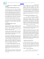
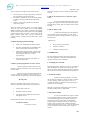
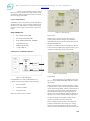
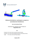
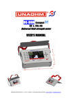
IJISET - International Journal of Innovative Science, Engineering & Technology, Vol. 2 Issue 9, September 2015.
www.ijiset.com
ISSN 2348 – 7968
Starter motor control system
R.Vishnurameshkumar1 ,A.Kingsly2, P.Karthikeyan3, R.Muthukumaran4 and B.Saran5
P
P
P
P
P
P
P
P
P
Assistant professor1 UG Scholar2, 3, 4, 5,, Department of Automobile Engineering, Dr.Mahalingam College of
Engineering and Technology, Pollachi-642003, Tamilnadu, India.
P
P
P
P
ABSTRACT
Starter motor converts electrical energy through a
battery into mechanical rotating energy. These
motors work under heavy load. They produce big
power in a short time and in a small volume. Starter
motor conveys its rotating energy with a pinion to the
flywheel. For initiating internal combustion engine,
the rotating moment of starter motors should be
requested being greater. The starter motor must be
rotating the flywheel at a minimum starting speed. It
must also continue support rotation during initial
combustion to maintain momentum until the engine
can sustain operation. The starter motor turns for
approximately 3 seconds during each starting
attempt. In each attempt the starter motor gear
bounces out and meshes with the flywheel attached to
the engine crankshaft. During the compression cycle
of each cylinder, the starter motor torque is high,
resulting in higher force on the starter gear teeth.
Because of the lack of over current protection, the
traditional starter control through solenoid easily
causes short circuit and bums out starter. So the
starter motor and its components are subjected to
either mechanical fault like wear, fractures of moving
parts or electrical faults like short interrupted circuit
and contact resistance increase etc. This paper
focuses on the need of electronic control unit based
starting system with some practical observations
made and also state of charge of battery is also
discussed.
Keywords:
Micro-controller, starter motor, battery, alternator
1. COMMON PROBLEMS:
1.1. BATTERY FAULT:
Automobile engine starting needs extremely high current,
in the range of 600 Amps peak for 250 ms, then a 150 A
to 300A sine wave at a reasonably stable voltage for 0.5
seconds to 3 seconds. Starter efficiency increases with
the higher deliverable voltage. Batteries needed for these
applications should be the capable of operation at the
temperatures ranging from -208 C to 508 C. In battery
fault, the battery cannot provide enough current in order
to turn the flywheel. In this Condition the battery is fully
discharged or there is problem on charging system and
therefore revolution of the motor will be too low.
1.2. STARTER MOTOR FAULTS
Starting of SI engines at low temperatures is easier than
CI engines due to sparking systems in the combustion
chamber and the fuel properties. By using the
conventional lubricating oils, fuels, etc., SI engines can
easily be started by using more volatile fuel having 10%
evaporation temperature at about 40°C. Starting of diesel
engine creates problems of cold starting at lowest
temperatures. While studying problems of cold starting,
they were observed that four operating factors influence
the diesel engine starting: (I) design of engine, (ii)
lubricating oil properties, fuels and coolant, (iii) battery
conditions and starter motor, and (IV) use of starting
aids. Hence, cold starting of IC engines under the subzero temperature conditions are a delicate operation. A
little carelessness can damage the whole engine, but if
proper precautions are taken and right type of starting
aid, fuel, coolant, lubricating oil, etc. are used, then a
summer like start can be achieved.
In the case of starter motors, the load of the machine is
an engine, with widely varying load torque, which is
dependent on the motor condition, external environment,
and multiple resonances. If any fault occurred on starter
motor, peak current during cranking will increase. The
mostly observed faults on starter motor and starter
system are; brush fault, battery fault, open circuit fault
(broken connection cables, loses battery pole etc.),
armature fault, field (excitation) winding’ fault and short
circuit fault. Because of improper starter mounting,
switching and lack of maintenance etc., teeth of the
starter pinion and flywheel ring gear may not mesh
properly and even impact each other. Due to improper
mesh or violent impacts, it can bring on to unstable, high
transient forces and torques and moments during starting,
and therefore troubles or failures such as gear teeth flake
off, meshing harness, tightly meshing, armature failure,
drive end housing fracture etc., are common in
application after a certain period of service time. As the
starter gear applies force, a moment comes where contact
between the starter and a flywheel gear is lost, followed
by a knock when contact is re-established. This
mechanical transient translates into speed and torque
transients and, subsequently, into a short transient of the
stator current.
515
IJISET - International Journal of Innovative Science, Engineering & Technology, Vol. 2 Issue 9, September 2015.
www.ijiset.com
ISSN 2348 – 7968
2. ALTERNATOR & CHARGING SYSTEM
CHECKS:
2.1. ALTERNATOR CHARGING OUTPUT:
The alternator in vehicles is the heart of the charging
system. It supplies all the power needed to keep the
battery fully charged and to run everything electrically in
the vehicle. The alternator is put up on the engine and is
belt-driven off the crankshaft pulley by a snaky belt or vbelt. The alternator produces alternate current (AC),
which is having changed to direct current (DC) by a six
diode rectifier, which is usually placed inside the back of
the unit. Diodes only pass current in one direction, which
they converted from AC current to DC. Three positive
diodes operate the positive side of the AC sine wave,
while three negative diodes operate the negative side.
The charging of alternator output increases in proportion
to the electrical load on the charging system and engine
speed. Output is low at idle and increases also with RPM.
Maximum output is typically attained at speeds above
2,500 RPM.
2.2. ALTERNATOR VOLTAGE
REGULATION
Charging output of the alternator is managed by a voltage
regulator which may be attached inside or back of the
alternator (internally regulated), or somewhere else
below the hood (externally regulated). On most
upcoming vehicles, the powertrain control module
(PCM) regulates charging output.
On older vehicles, the voltage regulator is electromechanical and used magnetic contacts to operate the
charging of alternator output. Since 1980s, most common
voltage regulators are solid-state electronic and utilize
transistors to operate charging output.
The actual output voltage induced by the alternator will
differ depending on temperature and load, but typically
about 1-1/2 to 2 volts will be higher than battery voltage.
At idle, charging systems will induce 13.8 volts to 14.3
volts with no lights or no accessories ON (some may
charge at little higher voltage depending on type of
battery, engine RPM, the battery's state of charge and
temperature). This can be measured by connecting the
positive (+) and negative (-) test pins of a voltmeter to
the battery posts while the engine is running.
2.3. ALTERNATOR CHARGING VOLTAGE
Most alternators are charging properly that should induce
a voltage of about 13.8 volts to 14.2 volts at idle
condition with accessories and lights OFF. For example,
Many Asian vehicles have higher charging voltages of
about 15 volts.
When the engine is started first, the charging voltage
should increase rapidly to about 2 volts above the base
battery voltage, then become smaller, leveling out at the
fixed voltage.
The exact charging voltage will differ according to the
battery's charging state, the loads on the vehicle's
electrical system, and temperature. The lower
temperature will higher the charging voltage, and the
higher temperature will lower the charging voltage. The
"normal" charging voltage on a typical application may
be 13.9 volts to 15.1 volts at 77 degrees Fahrenheit. But
at 20 degrees Fahrenheit below zero, the charging
voltage may jump as high from 14.9 volts to 15.8 volts in
short period of time. On a hot engine on the hot days, the
normal charging voltage might fall to 13.5 volts to 14.3
volts.
2.4. ALTERNATOR AMPERAGE OUTPUT
In addition to checking the alternator's
voltage output, you also want to check out its current or
amperage output. Amperage is strength of an electrical
current when the alternator generates at a specified
voltage and speed. Not long ago, an 80 amp alternator
was regarded as a high output unit. Latest model
alternators produce 120 to 155 amps or more. Current
output raises with engine speed, from around 20 to 50
amps at idle up to unit's maximum output at 2,500 RPM
or higher (refer to a service manual for the exact charging
output specifications for any desired vehicle).
Charging output can be evaluated with an
inductive amp probe clamped around BAT (B+) wire that
connects to an alternator. It can also be measured on the
alternator bench tester in an auto parts store.
Alternator power ratings can also be said in Watts
(voltage time’s ampere). The alternators in western
countries, vehicles are rated in watts only. The most
important point here is that the new alternator which is a
replacement of the original has the same power rating (in
amps or watts).So the charging system can give the same
power output as before. In fact, on some particular
applications upgrading alternator by replacing for a
higher output, may be recommended if the vehicle has a
repeated alternator failures, or the vehicle has an
aftermarket sound system which consumes more power
and the electrical accessories consumes heavy power
which may result in repeated failures.
3. PROBLEM DESCRIPTION:
The problem identified is “Basically in engines, diesel
engine need more effort for starting” for this reason there
are some of the cases discussed. The following
discussion tell about, the usual mistakes of a driver doing
while engine is not started and how it is going to affect
the starting system. Another common problem is “weak
compression” is also discussed.
CASE 1: (Lack of compression)
If the air and fuel is not compressed properly,
the combustion process will not work like it should.
516
IJISET - International Journal of Innovative Science, Engineering & Technology, Vol. 2 Issue 9, September 2015.
www.ijiset.com
ISSN 2348 – 7968
Lack of compression might occur for these reasons:
•
•
•
Piston rings are worn (allowing air/fuel to leak past
the piston during compression stroke).
The intake or exhaust valves are not sealed properly,
it results in allowing a leak during compression
stroke.
If there is a hole in the cylinder also affects the
compression stroke.
Increase in duration as well as current causes the starter
burn out.
CASE 4: (pressing the starter switch after engine
starts)
We observed that while traffic, people came
to forget their engine was started already but they again
press the starter switch. That will results in starter pinion
breakage
The most common problem "hole" in a cylinder appears
where the top of the cylinder (known as the cylinder
head) connected to the cylinder. Generally, the cylinder
and the cylinder head are bolt together with a thin gasket
pressed between them to ensure a good sealing. If the
gasket collapsed, small holes will occur between the
cylinder and the cylinder head, and these holes create
leakages.
Condition of the battery plays an important
role in starting system, if the battery is not in “good”
condition it is not have enough potential to ensure good
and quick start.
CASE 2: (during repeated starting)
It depends on,
•
Starter runs 15000 RPM at Armature Shaft.
•
By means of Reduction gear the RPM comes
down to 3000 which increase the torque.
•
•
When starter engages with Fly wheel it turns
the Engine 300 RPM since the Pinion of the
starter and Fly wheel are 1: 10 ratio
approximately.
Since the Driver operates more number of
Time the starter burn.
CASE 5: (Battery state)
•
Previous Usage of the battery
•
Alternator condition
•
Condition of the electrolyte.
4. APPROACH:
By observing these situations we had an approach to
solve these problems it ensures the safety and better
operation of starter motor and battery.
CASE 3:(prolonged application of starter switch)
1. Cranking for 3 seconds:
When we apply the starter switch for long
time heavy current is allowed to flow on the copper coil
of starter motor.
By limiting the starter motor to run only for 3 seconds we
limits the duration of current flow in the armature coil
and we can able to reduce the heat generation by limiting
the amount of current flow and duration of current flow.
When a current of I amperes passes through
a circuit of resistance R ohms for a period of time (t)
seconds, then the heat generated is given by the equation.
2. Crank for 3 times:
H=I2Rt joules
P
P
The above equation is known as the joule’s law of
heating. It states that produced heat is proportional to,
•
Square of the current (I).
•
Resistance of the circuit (R)
•
The time (t) during which the current flows
through the circuit.
Heat produced in calories can be expressed as
H=I2Rt/4.18 calories
(1 calorie=4.18 joule)
P
P
Instead of cranking repeatedly, we reduce
the repetition of cranking to 3 times also after 3 seconds
of every cranking starter motor kept in “idle” for 2
seconds, this duration is helpful for restoring the power
of battery for next cranking.
With this, we attempt to minimise the power spent on
cranking so battery state is safeguarded.
3. Alternator output:
In order to find whether the engine is started
or no, a standard reference value is required. Normally,
we identified the engine start condition with sense of
sound came from the engine and so we utilised the
alternator output voltage as reference for engine start.
Usually, idling of engine at this condition alternator
output voltage ranges from 13volt - 14.5volt. We adopted
13volt as reference value and that implies “Engine is
started”.
517
IJISET - International Journal of Innovative Science, Engineering & Technology, Vol. 2 Issue 9, September 2015.
www.ijiset.com
ISSN 2348 – 7968
Below 13volt of alternator output, it is taken
that engine was not started and we adopt a small period
of time after cranking and alternator reaches 13volt and
above thus engine was started.
4. State of the battery:
If the battery state is not good the potential of the battery
drained in faster rate, we are restrict the potential do not
fall below 8V.so that feedback is taken from the battery
in order to cut the supply of starter motor to protect the
battery.
REQUIREMENTS:
Figure 5.2: Self-start ON
•
PIC CONTROLLER CHIP.
Figure shows,
•
PIC EVALUATION BOARD.
•
PULL DOWN RESISTOR.-10KOHM
•
LCD DISPLAY 16x2.
Initially driver is giving an input to the system by
pressing starter switch.so that processes initiated as
instructed in the program which is fed into PIC16F877A
MICROCONTROLLER
•
SIMPLE DC MOTOR.
•
12 VOLT RELAY
In order to visualize the process are being done. We use
LCD16*2 which is added in the program coding as given
in chapter 3 methodology, under program code.
5. RESULTS AND DISCUSSIONS
Figure 5.3:First cranking
Figure 5.1 Block Diagram
Using PROTEUS V7.7SP2.we had simulated our
program. Under varying condition of the following,
•
Driver command
•
Condition of battery
•
Alternator output
Response of starter motor is checked
Figure shows.
The initial process is a command given by the
driver is read by MICROCONTROLLER and it initiates
the cranking.
Starter motor draws heavy current from battery in order
to generate heavy torque to turn the flywheel the amount
current drawn falls gradually within in a small interval of
time because of increase in back emf at end of starter
motor armature the back emf is generated (based on
faraday’s law of electromagnetic induction). Because of
the rotation of armature in the permanent magnet field.
It is like, the output of starter motor rotation causes
increase in potential at the starter motor end.
Before cranking, potential at battery end is high and
potential at starter motor end is nearly zero .within a
fraction of second, the potential of starter motor end
increases so that current drawn by the starter motor from
518
IJISET - International Journal of Innovative Science, Engineering & Technology, Vol. 2 Issue 9, September 2015.
www.ijiset.com
ISSN 2348 – 7968
the battery decreases gradually.at this period of time the
engine is cranked (in seconds).
The healthy battery remains in good condition. That is, it
withstands its potential after cranking, if the engine is
started means, alternator produces steady output voltage
by utilizing engine’s idle speed which will vary 13 To
14.5 volt
If these situation are obtained then the LCD shows
“engine start”.
Figure shows,
In some place usually in traffic, the driver forgets his/her
engine is running, drive again pressing starter switch
which leads to starter motor pinion teeth breakage and
also affects the gear profile of flywheel
In order to eliminate this situation, PIC
MICROCONTROLLER receives input signal from
battery and alternator. Starting from battery ON until
battery OFF.
If the driver crank the engine while the engine is running
in idling speed, microcontroller omits that driver’s signal
as simulated below
Figure 5.4: Conditions satisfied
Figure shows,
The condition of battery and alternator voltage output
plays key role in controlling the operation of starter
motor. While cranking the potential of battery slightly
decrease which will not fall below 8volt at average rated
conditions.
In case the condition of battery is not good due to any
reasons (insufficient charging alternator fault leakage in
battery, electrolyte specific gravity fall).the potential falls
below 8 volt which is not desired for battery operation
and it affects the life of battery
So using relay cut off the supply to the starter motor in
order to protect the battery. Immediately cranking or
stopped and wait for 3 seconds for next cranking
This process is repeated for 3 times when the battery
potential falls below 8 volt. LCD shows “engine not
started”
Figure 5.6: Omitted crank
Figure shows,
In order to verify the engine is started, we utilize the
information received from battery and alternator from
ON To OFF of the vehicle, by checking the following
conditions made available in microcontroller comparing
with actual outputs from battery and alternator terminals.
They are,
•
Battery potential is greater than 8 volt
•
Alternator output voltage is greater than 13 volt
(>13v)
(>8v)
If the above conditions are not satisfied the process
proceeds further after the first cranking, the process
follows the instructions written in the
MICROCONTROLLER as second, third cranking until
those two conditions are satisfied.
6. ADVANTAGE:
•
Increasing Battery Life.
•
While the Engine is Running, Turning ON the
starter motor is omitted automatically.
•
Increasing service life of Starter Motor.
Figure 5.5: Conditions not satisfied
519
IJISET - International Journal of Innovative Science, Engineering & Technology, Vol. 2 Issue 9, September 2015.
www.ijiset.com
ISSN 2348 – 7968
7. REFERENCES
[1]. IGBT based Induction Motor Soft Starter by
Sneha M Mukare, ‘IOSR Journal of Electronics and
Communication Engineering’ (IOSR-JECE) ISSN: 22782834, ISBN: 2278-8735, PP: 27-32.
[2]. Energy Efficient Battery Management by CarlaFabiana Chiasserini, Member, and Ramesh R. Rao,
Senior Member,’IEEE JOURNAL ON SELECTED
AREAS IN COMMUNICATIONS’, VOL. 19, NO. 7,
JULY 2001).
[3]. An Overview of Microcontroller Unit: From
Proper Selection to Specific Application by Manas
Kumar Parai, Banasree Das, Gautam Das, ‘International
Journal of Soft Computing and Engineering’, (IJSCE)
ISSN: 2231-2307, Volume-2, Issue-6, January 2013.
[4]. Battery Monitoring System using Microcontroller
by S. N. Patil, Sangmeshwar S. Kendre, Dr. R. C. Prasad
‘International Journal of Computer Applications’, (0975
– 8887) Volume 28– No.6, August 2011).
[5]. An overview of Automobile Starting System
Faults and Fault Diagnosis Methods by.
Chandramohan.G, Senthil Kumar.M., Rudramoorthy.R,
Ashok Kumar.L, Suresh Kumar.R. ‘ARPN Journal of
Engineering and Applied Sciences’, VOL. 7, NO. 7,
JULY 2012 ISSN 1819-6608.
Mr.Vishnurameshkumar.R is an Assistant professor in
Automobile Engineering Department, Dr.Mahalingam
College of Engineering and Technology, Pollachi,
Tamilnadu. His research area is in Automotive Electrical
system. He has presented paper in 1 International
conference.
Mr.Kingsly.A is an UG Scholar in Automobile
Engineering Department, Dr.Mahalingam College of
Engineering and Technology, Pollachi, Tamilnadu.
Mr.Karthikeyan.P is an UG Scholar in Automobile
Engineering Department, Dr.Mahalingam College of
Engineering and Technology, Pollachi, Tamilnadu.
Mr.Muthukumaran.R is an UG Scholar in Automobile
Engineering Department, Dr.Mahalingam College of
Engineering and Technology, Pollachi, Tamilnadu.
Mr.Saran.B is an UG Scholar in Automobile
Engineering Department, Dr.Mahalingam College of
Engineering and Technology, Pollachi, Tamilnadu.
520