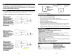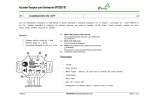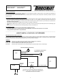
1
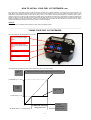
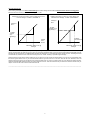
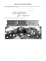
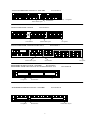
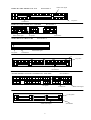
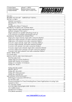
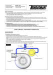
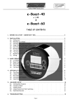
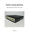
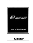
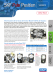
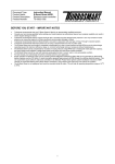
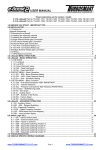
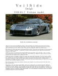
Product Name:
FCD2
Product Description: Fuel Cut Defender
Product Number:
TS-0303-1002
-----------------------------------------------------------------------------------------------------------------------ABOUT THIS PRODUCT
Most late model cars have in-built defence mechanisms to guard against increases in boost pressure. Such systems are important but
can be an obstacle when increasing boost pressure
The Turbosmart FCD2 will allow boost pressure to be increases above the factory level and prevent momentary shutdown of the fuel
injection system.
IMPORTANT NOTES ON YOUR BOOST CONTROLLER
• Once the fuel cut defender has been installed, the factory over-boost fuel cut will no longer operate at the factory level. The boost
can now be raised to dangerous levels which can damage your engine if it is not capable of handling higher boost pressures. Be
extremely cautious when increasing the boost pressure above the factory level. Seek the advice of your local tuner or performance
specialist for further information
• The FCD2 is not waterproof and should not be mounted in the engine compartment.
O
• The adjustment dials do not turn 360 , they start at 1 and finish at 10. Do not force them past these points as this will damage your
FCD2
• Before setup the unit should be set to the following settings, Clamp=10, Release=10.
RECOMMENDATIONS
• Your FCD2 is fitted and tuned by an appropriately qualified technician.
• The Air Fuel (A/F) ratio is checked once the Fuel Cut Defender is set and/or boost pressure is increased.
• Tuning should be performed on a dynamometer
-----------------------------------------------------------------------------------------------------------------------HOW TO INSTALL YOUR FUEL CUT DEFENDER
BEFORE INSTALLING THE FCD2
It is important to determine if the vehicles electronic control unit (ECU) receives its boost reference signal from the manifold absolute
pressure (MAP) sensor or air flow meter (AFM). Failure to connect the FCD2 to the correct sensor could cause severe engine damage.
Turbosmart recommends consulting the manufacturer service manuals before installation.
WIRING:
RED Wire:
BLACK Wire:
WHITE Wire:
BLUE Wire:
Connect to 12V positive supply from ignition switch (not directly from the battery)
Connect to Negative supply (earth/ground on vehicle chassis)
Connect to MAP sensor or AFM meter output signal wire
Connect to ECU boost reference input wire (previously connected to MAP sensor or AFM output)
GROUND (NEGATIVE EARTH)
12V POSITIVE (SWITCHED
THROUGH IGNITION)
BLACK WIRE
FCD2
RED WIRE
BLUE WIRE (FCD OUTPUT)
WHITE WIRE (FCD INPUT)
ECU
MAP sensor
or AFM
SENSOR
OUTPUT
WIRE
CUT HERE
ECU INPUT WIRE
YOU MUST CUT THE WIRE FROM THE SENSOR TO
THE ECU. THE FCD2 IS THEN INSTALLED BETWEEN
THE SENSOR AND ECU AS SHOWN
1
HOW TO INSTALL YOUR FUEL CUT DEFENDER cont.
The output wire of your MAP sensor or AFM can be easily located using a digital multimeter or consulting your service manual if not
listed. When using a digital multimeter ensure the meter is set to read voltage in the 0-10V range. Place the negative probe of your
multimeter on the vehicles chassis and with the car idling, slowly rev the engine. With the positive probe you should be able to read a
change in output on one of the wires connected to the MAP sensor or AFM with increasing rpm. Alternatively with ignition switched and
engine off, blow air through the AFM or apply pressure to the MAP sensor using a vacuum/pressure source. This should also give a
change in voltage on the sensor output wire. Once you have identified the correct wire the wire should be cut and the input and output
of the FCD2 should be connected to the wires as shown in the above diagram.
WIRING:
Mount the FCD2 in a suitable location within the cabin using the supplied screws.
-----------------------------------------------------------------------------------------------------------------------TUNING YOUR FUEL CUT DEFENDER
This view shows the two adjustments on the FCD2.
Green Indicator LED to show
when unit is clamping voltage
signal
Red Indicator LED to show
when unit has released voltage
signal
CLAMP DIAL
RELEASE DIAL
The Graph below illustrates the effect of each adjustment dial on the sensor output.
Voltage to
ECU
Voltage from sensor into FCD vs. output voltage from FCD to ECU
CLAMP Setting 10 = 5.5V
Adjustable
“CLAMP”
Voltage
Clamp voltage
level
CLAMP Setting 1 = 3V
RELEASE Setting 1 = CLAMP Voltage
“RELEASE” clamping
voltage adjustment
2
Voltage
From Sensor
RELEASE Setting 10 = 5.5V
SETTING EXAMPLES
These setting examples are to aid in understanding the various settings of the FCD2 and should not be used as a tuning guide.
IMPORTANT! See following instructions for tuning your FCD2.
Voltage from sensor into FCD vs. output voltage from FCD to
ECU for settings: CLAMP: 1, RELEASE: 6
Voltage from sensor into FCD vs. output voltage from
FCD to ECU for settings: CLAMP: 5, RELEASE: 8
Voltage to
ECU
Voltage to
ECU
“CLAMP”
Voltage (4.1V)
@ Setting 5
“CLAMP”
Voltage
(3V)
@ Setting 1
Voltage
From
Sensor
“RELEASE” voltage 4.4V @
Setting 6
Voltage
From Sensor
“RELEASE” voltage 4.9V @
Setting 8
For most vehicles the setup is quite simple. On a dyno, bring the engine onto full boost until the factory boost cut is activated, taking
note of the boost level at which this occurs. Then turn the clamp adjustment dial on the front of the FCD2 ANTI-CLOCKWISE until the
indicator light just illuminates. The GREEN LED indicator light should turn on just before the factory boost cut point. Activating the boost
cut defender any earlier than this could cause the engine to run “LEAN” resulting in possible engine damage.
With the clamping level set the release voltage or new cut point can be set. When the release dial is set to 10 the unit will release when
the sensor signal reaches 5.5V. If you know the boost level that you want the fuel cut to return with the aid of an assistant, drive the
vehicle bringing the engine onto full boost at the maximum boost level you want to run before fuel cut. Then adjust the release dial anticlockwise until the RED LED illuminates and vehicle begins to fuel cut. This dial should be set just above the maximum boost level you
require. Check the A/F ratio once the FCD2 has been set.
------------------------------------------------------------------------------------------------------------------------
3
VEHICLE SPECIFIC WIRING DIAGRAMS
The following tables are vehicle specific ECU wiring diagrams for locating the airflow meter signal, ignition and ground wires. Be sure to
cover any exposed connections with electrical tape.
ECU DIAGRAMS ARE VIEWED
FROM FRONT ON
Each diagram has the ECU locations specified by the key and diagram below.
A Passenger Side Lower Dash
B Left of the glove box
C Passenger Side foot rest
D Behind the glove box
E Behind the centre console
F Under the driver seat
G Under the passenger seat
H Near the steering column
I Right of the meter panel
J Driver side lower dash
K Right of the centre console
L Engine bay
M Front side of the boot
N Back of the driver seat
C
I
E
H
F
C
E
K
J
A
G
4
TOYOTA SOARER JZZ30 1JZ-GTE 91.5 ~ ONWARDS
ECU location: C
12v ignition
Ground/earth
Airflow meter signal
TOYOTA SUPRA JZA80 – 2JZ-GTE
Ground/earth
ECU location: C
Airflow meter signal
12v ignition
ECU location: C
TOYOTA SUPRA JZA80 – 2JZ-GTE VVTi M/T ONLY
Airflow meter signal
Ground/earth
12v ignition
ECU location: E
MITSUBISHI GTO Z16A 6G72 90.10 ~ ONWARDS
MITSUBISHI LANCER CE9A 4G63 93.10 ~96.7 & CD9A 4G63 92.10 ~ 93.9
12v ignition
Ground/earth
MITSUBISHI ECLIPSE D32A 4G63 95.6 ~ ONWARDS
12v ignition
ECU location: B
Ground/earth
ECU location: E
Airflow meter signal
5
MAZDA RX-7 FD3S 13B-REW 91.12 ~95.11
Airflow meter signal
ECU location: A
12v ignition
Ground/earth
MAZDA RX-7 FD3S 13B-REW 95.12 ~ONWARDS
Airflow meter signal
ECU location: A
12v ignition
MAZDA RX-7 FC3S 13B 85.19 ~88.8
Ground/earth
ECU location: C
Airflow meter signal
12v ignition
Ground/earth
SUBARU LEGACY BC5 & BF5 EJ20G 89.2 ~ 93.9
ECU location: H
Airflow meter signal
12v ignition
Ground/earth
SUBARU IMPREZA GC8 EJ207 & GF8 EJ205 98.9 ~ ONWARDS
ECU location: C
12v ignition
Ground/earth
Airflow meter signal
ECU location: C
SUBARU IMPREZA GC8 & GF8 EJ20K 96.9 ~ 98.8
12v ignition
Airflow meter signal
6
Ground/earth
DO NOT USE ANY TURBOSMART PRODUCT UNTIL YOU HAVE CAREFULLY READ
AND UNDERSTOOD THE FOLLOWING AGREEMENT.
Please call if you have any questions or do not understand this agreement. Refer to our brochure, website or catalogue for
terms and conditions and further information regarding your product. Turbosmart appreciates your business and pride
ourselves on our customer service. We are always happy to offer you advice and will provide you with help in any way we can.
The purpose of this agreement is to avoid any problems or hard feelings.
We sometimes make mistakes, as do our dealers, distributors and suppliers. Even customers can sometimes order the wrong
parts. Do not use, modify, install, trial assemble, nick, drop, scratch or adjust any part until you first check for any damage.
Damage must be reported immediately. NO EXCEPTIONS. If there are any components missing please contact your
authorised reseller immediately upon receipt of your shipment. Missing components must be reported within five (5) business
days of receipt. Parts returned for any reason MUST BE IN RESALABLE CONDITION. It is YOUR responsibility, “THE
CUSTOMER” to carefully package any returns to avoid shipping damage. Insurance is highly recommended. Credit cannot be
issued for damaged goods.
Turbosmart Pty Ltd warranties the quality of the products it designs and manufactures to be free of defects in material and
workmanship. This limited warranty is extended only to the original purchaser and may not be transferred or assigned. This
limited warranty applies to any product, which after careful inspection by Turbosmart Pty Ltd, after receipt of the product from
our authorised reseller, is found to have a defect in either material or workmanship. Any modifications to the product will void
any and all warranties and will not be exchanged. Before installation, check new car warranty. Turbosmart Pty Ltd is not
responsible for voiding any original manufactures warranty.
All warranty claims must be returned to the authorised reseller, you must return the product and sales receipt, at your own
expense, accompanied by a letter stating the reason for the claim. Proof of purchase must be provided with any warranty claim
and will be verified with the authorised reseller from which the product was purchased.
If all the above procedures are followed, and the product is found to be defective in either workmanship or material, Turbosmart
Pty Ltd shall either repair or replace the product, at its sole discretion, and sole cost. This limited warranty does not cover or
apply to any personal injury, labour charges or any other incidental costs or damages caused by the defective product. The
individual purchaser acknowledges and agrees that the disclaimer of any liability for personal injury is a material term for this
agreement and the individual purchaser agrees to indemnify Turbosmart Pty Ltd and to hold Turbosmart Pty Ltd harmless for
any claim related to the item of the equipment purchased. Under no circumstances will Turbosmart Pty Ltd be liable for any
damages or expenses by reason of use or sale of any such equipment.
THIS LIMITED WARRANTY IS THE ONLY EXPRESS WARRANTY, WHICH APPLIES TO TURBOSMART PTY LTD
PRODUCT AS EXPRESSLY GIVEN IN LIEU OF ANY OTHER WARRANTY EXPRESSED OR IMPLIED, INCLUDING THAT
OF MERCHANTABILITY. ANY IMPLIED WARRANTY INCLUDING THAT OF MERCHANTABILITY AND/OR FITNESS FOR A
PARTICCULAR PURPOSE IS HEREBY LIMITED BY THE SAME TERMS AND TIME LIMITATIONS SET FORTH IN THIS
LIMITED EXPRESS WARRANTY AND OTHERWISE EXCLUDED.
EXCEPT FOR THOSE OBLIGATIONS ASSUMED HEREIN, TURBOSMART PTY LTD ASSUMES NO OTHER OBLIGATIONS
IN CONNECTION WITH THE SALE OF ITS PRODUCTS.
IN THE EVENT THAT THE INDIVIUDAL PURCHASER DOES NOT AGREE WITH THIS AGREEMENT THE BUYER MAY
PROMPTLY RETURN THIS PRODUCT, IN A NEW AND UN-USED CONDITION, WITH A DATED PROOF OF PURCHASE,
TO THE PLACE OF PURCHASE WITHIN SIXTY (60) DAYS FROM THE DATE OF PURCHASE FOR A FULL REFUND.
THE INSTALLATION OF THIS PRODUCT INDICATES THAT THE INDIVIDUAL PURCHASER HAS READ AND
UNDERSTOOD THIS AGREEMENT AND ACCEPTS ITS TERMS AND CONDITIONS.
Happy motoring!
The Turbosmart Team
Turbosmart Pty Limited P.O.Box 264 Croydon, NSW, 2132 Australia ABN: 69 081 069 794
Tel: +(612) 9798 2866 Fax: +(612) 9798 2826 Email: [email protected]
www.turbosmart.com.au www.turbosmartusa.com www.turbosmart.co.nz
7