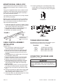
1
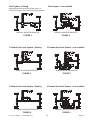
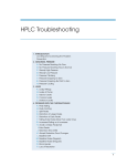
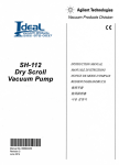
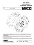
DUAL CABLE LOCK
Installation and Service Instructions
Brake Fluid
Model Numbers
02-640-169
02-640-201
Mineral Based Hydraulic Oil
Model Number
02-640-202
READ GENERAL INSTALLATION GUIDELINES SHEET (FORM NO. 81-600-001) BEFORE PROCEEDING
1. All MICO locking devices are supplemental
safety equipment which provide additional brake
holding action when used with existing vehicle
parking brake.
2. The Low Pressure Warning Switches must be
used in combination with an audible or visual
alarm to signal any loss of system pressure. The
Low Pressure Warning Switches are explained in
the Operating Instructions (Form No. 81-660-016).
Do not disconnect Low Pressure Warning
Switches.
3. All lines, fittings and adjacent areas must be
cleaned of dirt or road residue before any lines
or fittings are disconnected. Special care must
be taken so dirt and road residue are not allowed
to enter hydraulic brake system. This can contaminate the system and interfere with proper
operation of brakes and MICO locking devices.
4. Follow procedures outlined in Vehicle Manufacturer’s Service Manual or SAE Standards when
making new connections or adding to existing
brake systems. Use only steel brake tubing conforming to SAE specifications.
5. Use only brake fluid conforming to latest SAE or
DOT Standards. Improper or contaminated brake
fluid may cause gummy deposits and softening
and swelling of other rubber seals in the entire
brake system. Such a condition must be corrected
immediately.
6. Do not use sealants, tapes, teflon or cement
compounds on any connections or fittings.
These sealants or compounds can contaminate
the hydraulic brake system and interfere with the
operation of brake components or MICO locking
device.
7. All fittings and connections must be in good
condition and tightened to proper torque values
as specified in the Installation and Service
Instructions.
8. Separate models of MICO locking devices are
available for brake fluid and for mineral based
hydraulic oil. Select model to conform with the
type of fluid in system.
9. Brake hoses, brake lines, MICO locking device,
brake components, cylinders, and all fittings must
be routinely inspected for leaks, damage or wear.
Adequate fluid levels must be maintained. In the
event of any loss of fluid, brake system must be
carefully inspected for leaks.
10. After installation, bleed system according to
vehicle manufacturer’s recommendations.
11. Follow INSPECTIONS and TESTS section as
outlined in the Operating Instructions.
12. The self-adhesive warning label accompanying
each MICO locking device must be affixed in cab
in view of operator.
13. The Operating Instructions must be placed in
cab of vehicle in a place available to operator.
MICO could not possibly know of and give advice with respect to all conceivable applications in which this product may be used and the possible hazards and/or
results of each application. MICO has not undertaken any such wide evaluation. Therefore, anyone who uses an application which is not recommended by the
manufacturer, first must completely satisfy himself that a danger will not be created by the application selected, or by the particular model of our product that is
selected for the application.
MICO has made every attempt to present accurate information in catalogs, brochures and other printed material. MICO can accept no responsibility for errors from
unintentional oversights that may exist. Due to a continuous program of product improvement, materials, specifications, and product documentation are subject to
change without notice or obligation.
MICO is a trademark and registered trademark of MICO, Inc. MICO is registered in the U.S. Patent and Trademark Office as well as in Australia, Canada, Indonesia, Japan, Peoples Republic of China, South Korea, and the European Community.
MICO, Incorporated
Innovative Braking and Controls Worldwide
Form No. 81-660-015
Revised 2008-12-03
1911 Lee Boulevard / North Mankato, MN U.S.A. 56003-2507
Tel: +1 507 625 6426 Fax: +1 507 625 3212
www.mico.com
MOUNTING DUAL CABLE LOCK
The dual cable lock is remote mounted with a cable
which should be located in cab for operator’s convenience.
12. Position operating arm in unlocked position. Push
knob to within 1/4 inch of fully closed position and
trim inner core 1/2 inch beyond clamp, then tighten
set screw.
Tubing is not supplied because of the variation in each
installation. Install tubing using shortest and most protected route. Use same size tubing when replacing a
line, unless otherwise specified.
Thoroughly inspect port threads for any foreign material
after removing vinyl plugs.
Bleeder screws provided must be used on installation.
After installation, dual cable lock may contain air. This
air, if not removed, will cause an ineffective and perhaps inoperative brake system.
FIGURE 2
1. Locate dual cable lock on inside or outside of frame
rail. Be sure that the lock does not interfere with the
other vehicle components, (See Figure 1).
2. Using the dual cable lock mounting bracket as a
template, drill necessary mounting holes.
3. Install bolts, lock washers, and nuts.
FIGURE 1
FIGURE 3
RECOMMENDED ACTUATOR
MOUNTING LOCATION INSIDE OR OUTSIDE FRAME
RAIL
TORQUE SPECIFICATIONS
All hydraulic line connections must be torqued to specifications listed below and be free of leakage.
CABLE CONTROL ASSEMBLY
INSTALLATION
(Figures 2 & 3)
1. Drill 1/2 inch hole in dash panel (universal
mounting bracket may be used instead).
2. Remove knob and lock nut from cable assembly.
3. Remove first 1/2 inch nut from cable assembly,
leaving lock washer and second 1/2 inch nut on
assembly.
4. Insert threaded end of cable through 1/2 inch hole
from backside of dash panel.
5. Replace and tighten 1/2 inch nut securing cable
to dash. Torque nut 16.3-23.1 N·m (12-17 lb·ft).
6. Replace lock nut and knob allowing 1/4 inch
clearance between lock nut and first 1/2 inch nut.
7. Insert cable through firewall and route to cable
clamp attached to dual cable lock. Avoid sharp
bends and kinks.
8. With cable held in position, move knob and check
for binding. If binding is present, reposition cable.
9. Remove inner core and trim outer sheath of cable
to fit.
10. Insert end of sheath into cable clamp on dual cable
lock and tighten. Install rubber boot on outside of
cable housing, slide on at least 1/4 inch.
11. Insert inner cable core and feed through core clamp
on operating arm of dual cable lock.
MICO, Inc.
Thread Size
Torque
3/8-24
7/16-24
1/2-20
9/16-18
10.9-20.3 N·m (8-15 lb·ft)
16.3-23.1 N·m (12-17 lb·ft)
16.3-23.1 N·m (12-17 lb·ft)
20.3-33.9 N·m (15-25 lb·ft)
CONNECTING THE BRAKE LINES
(Figures 4, 5, 6, 7, 8 & 9)
For all brake systems in use today, including antilock, the MICO Dual Cable Lock must be installed
between last hydraulic component in supply line and
wheels.
(2)
Form No. 81-660-015
Revised 2008-12-03
Dual System - Lock Installed
Dual System - Existing
Warning/Proportioning Valve and Rear Anti-Lock
Control Valve may not be used in some Dual Systems.
FIREWALL MOUNTED BOOSTER
FIREWALL MOUNTED BOOSTER
FIGURE 4
FIGURE 5
3-Channel Anti-Lock System - Existing
3-Channel Anti-Lock System - Lock installed
REMOTE MOUNTED BOOSTER
REMOTE MOUNTED BOOSTER
FIGURE 6
FIGURE 7
4-Channel Anti-Lock System - Existing
4-Channel Anti-Lock System - Lock Installed
FIREWALL MOUNTED BOOSTER
FIREWALL MOUNTED BOOSTER
FIGURE 8
FIGURE 9
Form No. 81-660-015
Revised 2008-12-03
(3)
MICO, Inc.
BLEEDING PROCEDURE
CONNECTING HORN RELAY
AND LOW PRESSURE WARNING
SWITCHES
See General Guidelines Sheet (Form No. 81-600-001)
for bleeding guidelines.
The hydraulic brake system must be bled whenever any
line has been disconnected. There are two methods of
bleeding hydraulic systems, pressure bleeding and
manual bleeding. Both methods are acceptable and
adequate but pressure bleeding is recommended if the
equipment is available. Follow bleeding procedure and
instructions as specified by vehicle manufacturer.
(Figure 10)
If the vehicle does not have an auxiliary horn relay,
install one as shown. The auxiliary horn relay must be
used when the electrical load exceeds 3 amps. Do not
make connections from warning circuit directly to battery terminal as pressure switch contacts will be
damaged.
Use only Brake Fluid SAE J1703 or DOT Brake Fluid
or brake fluid specified by the vehicle manufacturer.
Never reuse brake fluid that has been drained from
the system.
Before moving vehicle, a firm pedal must be achieved
when dual cable lock is in full release position. If a firm
pedal is not achieved, repeat bleeding procedure for
dual cable lock and brake system until a firm pedal is
achieved. Make several brake applications with vehicle
stationary and check fittings for leaks.
The MICO Dual Cable Lock must be installed according to these instructions and all fittings and connections
must be in good condition and tightened to proper
torque values. If contaminants have been introduced
into the brake system a severe abrasion of all components may occur which may result in a loss of pressure. The dual cable lock is not field serviceable. If
dual cable lock is damaged by contaminants or
impaired in any way, return to MICO, Inc. for reconditioning or replacement and service other components
accordingly.
Typical Relay
FIGURE 10
TROUBLESHOOTING GUIDE
Dual cable lock is not field serviceable - do not attempt disassembly. If dual cable lock is damaged by contaminants or
impaired in any way return to MICO, Inc. for reconditioning or replacement and service other components accordingly.
PROBLEM
System locked up and
brakes will not release
Brake system will not
hold pressure
Low Pressure Warning
Switch operates inadvertently or will not shut off
Spongy or soft brake
pedal
MICO, Inc.
POSSIBLE CAUSE
Master cylinder or booster
malfunction
Lock installed incorrectly
between master cylinder
and wheels.
Leaking conditions in tubing
and/or fittings
Leak in wheel cylinder or
caliper
Leak in lock valve
Locked up pressure leaking
off
Wiring improperly installed or
short in wires
Air in system, improper
bleeding at time of
installation
Slow leak in system
RECOMMENDED SERVICE
Bleed at booster. If brakes release, problem is booster.
Replace booster.
Replumb lock so it is installed between vehicle brake and last
hydraulic component in supply line.
Check all tubing and fittings in brake system. Tighten or replace
where required.
Check for moist condition. If moist condition exists replace or rebuild.
Replace lock.
See problems and conditions under heading "Brake system will not
hold pressure".
Check installation to conform with installation diagram. Check for
shorted wiring.
Follow good bleeding practices. Use pressure bleeder when
available.
Check fittings and wheel cylinder for leaks. Tighten or replace fittings.
Replace worn or damaged wheel cylinder.
(4)
Form No. 81-660-015
Revised 2008-12-03