1
Convert It
by
Michael P. Brown
with
Shari Prange
A Step-By-Step Manual
For Converting
An Internal Combustion Vehicle
To Electric Power
Published by
Future Books, an imprint of
South Florida Electric Auto Association
1402 East Los Olas Boulevard
Ft. Lauderdale, FL 33301
Electro Automotive 1993
All rights reserved. No part of this book may be reproduced, stored in a retrieval
system, or transmitted in any form or by any means, mechanical or electronic (including
but not limited to audio recording, video recording, computer files, and photocopying),
without permission in writing from the copyright holder.
Printed in the United States.
Printing history:
First edition published in the United States by Electro Automotive, 1989
Second edition published in the United States by Electro Automotive, 1990
Third edition published in the United States by Future Books, an imprint of the
South Florida Electric Auto Association, 1993
NOTICE: Every effort has been taken to insure that the information in this book is
accurate and complete as of the date of printing. Authors and publishers cannot accept
any liability for loss, damage, or injury incurred in connection with the use of this
information, or resulting from any errors in or omissions from the information given.
Publisher's Cataloging in Publication
(Prepared by Quality Books Inc.)
Brown, Michael P.
Convert it : a step-by-step manual for converting an internal
combustion vehicle to electric power / Michael P. Brown,
p. cm.
Includes index.
ISBN 1-879857-94-4
1. Automobiles, Electric. I. Title.
TL220.B76 1993
629.250*2
QBI93-1262
CONTENTS
1
2
3
4
5
6
7
8
9
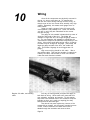
10
11
12
13
14
15
Introduction
5
Facts About Electric Vehicles
7
Safety
15
What You Need To Get Started
20
Choosing A Chassis
27
Removing The Internal Combustion
System
33
Installing The Motor & Adaptor
38
Batteries & Containment
49
Installing EV Components
64
Wiring
81
Final Hookup & Bench Testing
104
Suspension & Tires
109
Road Test, Driving, & Paperwork
113
Charging & Maintenance
120
Meeting The Press
125
ACKNOWLEDGEMENTS
I would like, to thank (in alphabetical order) the following people who have
provided technical information, proofreading, illustrations, and moral
support for this project: Herb Adams, John Anderson, Larry Burriesci,
D. Clarke, Scott Cornell, Eric Dieroff, Ruth MacDougall, Paul McCain, Bob
McKee, Steve Pombo, Steve Post, Rich Prange, and Damian Taylor.
Special thanks to N. Jell for making this third edition possible.
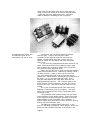
PHOTOGRAPHS
All photographs were taken by Shari Prange, unless otherwise credited, and
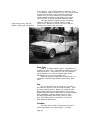
are individually the property of their respective contributors. The cover
photo shows author Michael Brown in Santa Cruz, California, with two of his
electric cars. In the foreground is a 1965 Fiberfab Aztec I body on a VW
Bug chassis. In the background is the 1981 VW Rabbit conversion prototype
for the Voltsrabbit™ kit.
FOR A CATALOG OF ELECTRIC VEHICLE COMPONENTS:
Send $5.00 (postage & sales tax included) to:
Electro Automotive
P. O. Box 1113-CI
Felton, CA 95018
Catalog also lists other electric vehicle books and videos for sale.
Outside the United States and Canada, please send $10.00. U.S. dollars
only.
TO ORDER COPIES OF THIS BOOK:
Send $24.95, plus $3.50 U.S. postage or $8.50 foreign postage, to above
address. In California, add sales tax. U.S. dollars only.
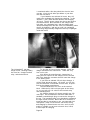
1
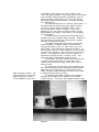
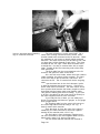
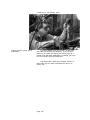
Author Michael Brown
Introduction
So you'd like to build an electric car. You're not
quite sure where to start, and that's why you're holding
this book. You've come to the right place.
You don't have to be a professional mechanic to use
this book or build your car. In fact, this manual was
written for the hobbyist or student. We'll start out
talking a little bit about what you can expect from an
electric car, just to be sure that the finished reality
will match your hopes. We'll talk about how to choose a
car to convert, and about how to strip it to make the
conversion easy. We'll go step by step through installing each component, and talk a little bit about why we
chose the component we did, and why we installed it the
way we did. At the end, we'll test the system, and talk
about charging, driving techniques, and suggested maintenance.
It doesn't matter whether your car starts life as a
gas or diesel car, front or rear drive, or even a pickup
truck or kit car. We'll address all of those variations
along the way.
We're going to be spending quite a bit of time
together for the next hundred or so pages, so we should
get to know each other a little first.
I already know you. You're intrigued by things that
are a little out of the ordinary or ahead of their time.
You find a kind of beauty in systems that are clean,
efficient, and simple. The proper engineering term is
'elegant'. You're concerned about increasing pollution,
and the increasing complexity of the internal combustion
engine. And you're excited by the idea of driving an
unusual car that you built yourself.
It's only fair that you know a little
about me, and my automotive background. First,
I'm a car person, and have been all my life.
I've been a professional mechanic for twentyeight years, and built some race cars along the
way. My experience with cars has been very
hands-on, not theoretical, and this has given
me a healthy respect for the ways things can go
wrong.
Having my own shop for seventeen years
also taught me about drivers. I learned what
people expect from their cars, and how they are
likely to neglect them, misuse them, or be
confused and intimidated by them. I believe
the interaction between the car and driver is
as important as the internal workings of the
machine.
In 1979, during the second gas crisis, one
of my customers asked me to build an electric
car for him. I had just quit racing, and was
ripe for an interesting project. As the owner
of a gas station, I could see a promising
future for electrics.
I built the car, which was a VW Bug
chassis with a Fiberfab Aztec body, and learned
a lot in the process. One of the things I
Page 5
"Build cars today
with parts that are
reliably available
today."
learned was that there were no good sources for parts.
There were scattered suppliers, many of them unreliable.
Most people were building cars w i t h scavenged surplus
parts from aircraft and homebrew concoctions that were
often frightening.
By the time the car was finished, Electro A u t o m o t i v e
was born: a conversion parts supply business. I spent
several years researching available production components
and seeking out manufacturers w h o w o u l d build to our
specifications. It was a very educational experience.
Over the years, I have built more than a dozen
electric cars, and have supplied parts and advice for
more than a hundred projects. Every car taught me
something, and these little bits of knowledge gradually
accumulated into a f e w basic principles t h a t express my
personal philosophy on electric cars. These are the
principles on which this manual is based.
Simplicity. Complexity means opportunities for
failure. The simpler a system is, the less there is to
go w r o n g . K I S S — K e e p it Simple, Stupid.
Ease of use. Simplicity of design must be matched
by simplicity of operation. An electric car should be
familiar and non-threatening, even to a novice driver.
Just as mechanical complications lead to mechanical
failures, complicated operating procedures lead to human
failures.
Proven reliability. I d o n ' t w a n t promises or
computer p r o j e c t i o n s — I want an actual track record.
People depend heavily on their cars. If the car isn't
reliable, it's worthless. Experimental technologies may
be great boons to electric cars someday, but the place to
test them is not in a car someone depends on to get to
work.
This is also a reason not to re-invent the wheel.
Automotive manufacturers put millions of engineering
design hours into their vehicles. It makes sense to use
as much of their design as possible, and make our o w n
modifications as compatible as possible w i t h the original
car.
Safety. For every component and s y s t e m , ask the
question, "What w o u l d happen if this failed?" Safety
generally means isolation: isolating the electricity to
a specific path, quickly isolating a failed component
from the rest of the system, and isolating potentially
dangerous components f r o m the passengers.
Availability. Build cars today w i t h parts that are
reliably available today. Not yesterday's out-of-production leftovers, and not t o m o r r o w ' s pre-production test
samples.
Affordability. There are some w o n d e r f u l technologies that are in production and readily available, and
have been proven to offer impressive performance.
However, if they cost five times the value of the rest of
the car, w h a t ' s the point?
The final result of following these principles will
be an electric car that is practical and pleasant to
drive for the average person in normal daily use.
Now let's figure out h o w an electric car might fit
into your life.
Page 6
2
"An EV is a
mission-intensive car.
It should not be
expected to be
all things
to all people."
Facts About Electric Vehicles
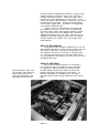
The workings of an electric vehicle (EV) are very
simple. Electricity moves from the power source, w h i c h
is probably a wall socket, through a charger, and into
the battery pack. When the ignition key is t u r n e d , the
main contactor closes, allowing electricity to move f r o m
the batteries to the speed controller. As the throttle
is depressed, the potbox sends a signal to the controller
telling it h o w much electricity to release to the motor.
The speed of the motor varies depending on h o w m u c h
electricity it gets. The motor is connected to the
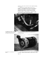
transmission by an adaptor plate. The power goes f r o m
the motor, through the transmission, and out to t h e
wheels as in a gas car. That's it in a nutshell. W e ' l l
talk about each of these parts in more detail later.
Before you build an EV for yourself, compare the
performance of a typical EV w i t h your intended uses for
it, and make sure the t w o are compatible. An EV is a
mission-intensive car. It should not be expected to be
all things to all people. A sports car is not expected
to carry lots of kids, and a luxury car is not expected
to be especially economical or suited to off-road
driving. Likewise, an EV has its o w n niche.
An EV is like a microwave oven. There are a lot of
things a microwave can't do, such as b r o w n f o o d , bake an
angel food cake, cook in metal pans, or prepare an entire
Thanksgiving dinner. A conventional oven can do all
those things. Yet the limitations of microwave ovens
haven't dampened their sales or popularity. Nor have
microwaves replaced conventional ovens, and no one is
expecting them to do so. What a microwave does, it does
very well. So it is w i t h an EV.
At the current state of the technology, there are
t w o applications into which EVs fit admirably.
Commuter Car. Most American households have more
than one car, and often one of them is used almost
entirely for commuting or local errand-running. In fact,
the average miles per day per vehicle in this country is
less than thirty. An EV is ideal for this type of use.
Some people think of an EV as a second car, and
that's fine, but it depends on h o w you define ' f i r s t ' and
'second'. Our gas car gets more mileage than the electric, but that's because we use it for long distance
driving. The EV gets used more often, but for shorter
trips. We think of our EV as our first car, because it's
our first choice.
Fun Car. An EV is a fun project to build, and will
give you the satisfaction of creating something t h a t is
uniquely yours. It's fun to drive, and if you have
graphics on it to identify it as electric, it will introduce you to a lot of friendly people at stoplights and in
parking lots.
There are myriad events for electric cars, ranging
from local parades and energy fairs, shows and road
rallies, on up to closed course races. If you choose,
you can be busy almost every weekend, collecting ribbons
and trophies, meeting people w h o are fascinated by your
car, and just having f u n .
Page 7
Your car can be demure and practical, or flashy and
futuristic. The choice is yours.
What's An Electric Car Like?
Passenger/Cargo Room. This depends on the car you
choose for conversion, and on your design. A car that
starts out as a two-seat sports car will probably end up
as a two-seat high-performance electric with little or no
cargo space. At the other extreme, a converted four-door
sedan or a small truck can provide quite reasonable performance while maintaining full passenger room, and most
or all of the original cargo space.
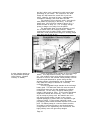
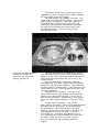
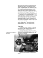
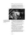
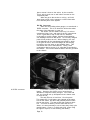
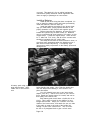
This high-performance electric
sports car (a converted 914
Porsche) has a top speed of
90 mph and a range of over
120 miles on a single charge.
Speed. Most modern EVs can do highway speeds of
50 - 60 mph. A car that is very heavy before conversion
will do less well. A very light car such as a kit car,
or a very aerodynamic sports car, may have a top speed of
80 - 90 mph. Acceleration is good, and is directly
related to the weight of the car and the quality of the
components used.
Horsepower. It is difficult to compare electric
motors to gas engines because their horsepower is rated
differently. Gas engines are generally rated on dynos
rather than in cars, with no load on them, not even
things like alternator belts. They are rated at their
peak horsepower. Electric motors, on the other hand,
tend to be rated under load, and at their continuous duty
rpm. A typical EV motor will have a continuous rating of
1 0 - 2 0 hp, which is all most cars need for cruising. It
will have a peak rating of around 60 - 70 hp.
Range. The typical modern conversion should have a
range of 60 - 80 miles in normal driving. This means
some freeway, but largely stop-and-go surface streets
with speeds of 30 - 40 mph. Higher-performance cars will
get 100 miles or more. Range will decrease with weight,
hills, or excessive stop-and-go traffic. There are many
things that can be done (to the car, and to the driver's
driving style) to improve range. We'll talk about these
Page 8
"Just try to park
an empty
gasoline car
and 'grow gas'!"
in more detail later.
There are two common questions that come up about
range. The first is, "What happens when I run out of
electricity?" You should be familiar with your car and
its range, and you should have a gauge to give you a
continuous reading on your state of charge, so dead
batteries will not suddenly sneak up on you. Also, an
electric car does not quit abruptly like a gas car.
Instead, in the bottom 20% or so of its charge, performance will begin to fade gradually.
If you misjudge and reach the point where the car is
moving too slowly to be safe in traffic, pull over and
park for a few minutes. The batteries will 'grow amps'
and recover some of their charge simply by resting. In
five or ten minutes, you can drive on again. If necessary, you can do this several times over several miles
until you get home, although it's not recommended as
regular practice. However, just try to park an empty gas
car and 'grow gas'!
Range Extenders. The second question is, "What if
I want to take a trip? Can I put some kind of range
extender on the car?" The most common strategy uses an
internal combustion engine, and the car is called a
hybrid. There are two types of hybrids. In a series
hybrid, a generator is used to provide electricity for
the motor, through a battery pack which acts as a storage
buffer. In a parallel hybrid, the engine is actually an
optional or auxiliary drive system for the car.
I have been personally involved in the building of
both types, and found them both to be unsatisfactory for
several reasons. For one thing, the hybrid concept
violates the principle of simplicity. Everything in the
internal combustion system and in the interface between
the systems is a potential problem. Also, this reintroduces all the pollution, maintenance, and expense we had
eliminated by converting to electric. One has to ask,
"Is this hybrid any cleaner than the original internal
combustion system?" It might actually be dirtier. Also,
is the gas mileage any better?
An electric car requires approximately 10 kw of
energy just to maintain cruising speed. Electricity
comes in two types: AC and DC. Alternating current (AC)
is household electricity. Its name comes from the fact
that the flow of the current regularly reverses its
direction. Direct current (DC) is battery current, and
it flows in one direction only. Since generators are
designed to put out AC current, this must be altered
through a rectifier to DC to go into the batteries. Take
a look at the size and price of a generator that can
produce 10 kw DC.
Hybrid systems are also bulky, noisy, and expensive.
In my opinion, they contradict everything an electric car
is supposed to be, and to little advantage. If you have
to go farther than the EV will take you, skip the complicated compromise and just drive a gas car.
Another suggested range extender is a solar panel.
This can certainly be used, but the trade-offs will not
be acceptable to most people. If you mount enough panels
to cover the entire roof of the car, and if the car sits
in the full sun all day long, the panels will only supply
about 5 miles more range. If you live in a sunny climate
Page 9
and don't drive much, perhaps this could meet a large
percentage of your needs. The continuous low level
charge will help extend the overall life of your batteries. However, the panel is heavy, unaerodynamic,
vulnerable to damage, and costs about $3,000.
This situation will not improve much, even though
solar panels are improving in efficiency. If the solar
panels were 100% efficient, instead of about 10%, it
would still take an array 10" x 10' to supply enough
power to charge a car solely from the panels.
The appropriate place for solar technology in relation to electric cars is at charging stations. Panels
covering the roofs of parking areas, with receptacles at
each stall, could provide some charge for working people
while their cars sit idle all day.
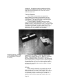
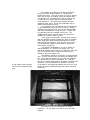
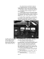
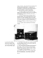
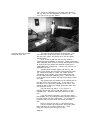
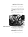
A solar charging station at
the Sacramento Municipal
Utility District. (Graphic
courtesy of SMUD.)
A third suggested range extender is the quick-charge
station. This may become a reality, but it isn't here
yet. One problem is that quick charging requires massive
amounts of current, and demand would probably coincide
with other peak demands for power during the day.
Another problem is that batteries can be damaged internally unless the charge is delivered in a carefully
controlled manner.
A fourth suggested range extender is the exchange
battery pack. This has been used with some success in
purpose-built race cars, but has problems for ordinary
conversions. For one thing, the typical battery pack
weighs 1,000 pounds or more. It will require specialized
equipment to handle this effectively. Also, in almost
any car except a pickup truck, the batteries are not in
one easy-to-reach module, but are in two or three
separate packages in places where it's impossible to get
a hoist or forklift. For the private individual, swapping battery packs means the added expense of a second
pack. For battery swaps in a service station situation,
all models of cars would have to use identical battery
configurations—an impossibility with conversions, and
highly unlikely even with ground-up designs.
Page 10
"The best
range extender
for an electric car
is a rental car."
A final suggested range extender is regenerative
braking. In regenerative braking, the braking action of
the car is used to generate electricity to charge the
batteries. Usually the drive motor is used as the generator, but sometimes an automotive alternator is used.
Regeneration is tricky in a DC s y s t e m . Special
wiring is required for both the motor and controller.
With improper installation, possible failures could
include unintended acceleration instead of braking, or
even damage to the motor. At this time, regenerative
braking for the hobbyist conversion violates the
simplicity and safety principles. This could change if a
regen system were developed by a major controller
manufacturer.
There is also some doubt about the value of regeneration. While it can be done effectively in an AC system
(which is more expensive), in a DC system it may not
actually provide enough charge to be w o r t h w h i l e . The
ideal regen condition is a long downhill. However, for
many people their downhill stretch is w h e n they first
leave home, and the batteries are fully charged. In this
instance, regen is useless.
In a typical conversion w i t h o u t regen, the motor
freewheels and offers no resistance on a d o w n h i l l . I
live in the mountains, and my driving style includes
using my downhill momentum to 'slingshot' up the next
hill. If I had regen, I would be charging the batteries
on the downhill, but the regen w o u l d also be slowing the
car and reducing my momentum. I w o u l d have more charge
going up the next hill, but less m o m e n t u m . I suspect the
loss of momentum would cancel out any charge gained.
Beyond this, range extension ideas start to include
windmills on the roof, perpetual motion machines, and
other schemes that are unworkable because they violate
several laws of physics.
Let's get back to the original question of w h a t to
do about a long trip. First, h o w often do you drive
farther than the electric car can go? Second, do you
have a gas car available for those trips? If not, then
the best range extender for an electric car, in my
opinion, is a rental car.
Recharging. If your battery pack is d r a w n d o w n
completely, it will take ten to t w e l v e hours to recharge
using a 110-volt charger. This can be reduced to 6 - 8
hours w i t h a 220-volt charger. When we get to the
section on chargers, w e ' l l talk more about the pros and
cons of each. Development is underway on the concept of
'pulsing' chargers that can charge batteries much faster
without damaging t h e m .
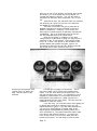
Number of Batteries. Most conversions use 6-volt
lead-acid golf car batteries. (We'll discuss different
types of batteries later.) In general, pack voltage
determines speed. A 72-volt system (twelve batteries) is
the minimum, just barely acceptable for a road-going
vehicle. This is only acceptable in a very light car
that is never intended for freeway use. It will have
performance similar to the original 1 2 0 0 CC VW Bugs.
Most conversions use sixteen batteries, for a total
pack voltage of 96 volts. For higher performance, heavy
cars, or w o r k vehicles such as light pickup t r u c k s , a
120-volt system w i t h t w e n t y batteries is recommended.
Page 11
EVs Don't Need:
Gasoline
Oil Change
Tune-up
Spark Plugs
Cap & Rotor
Valve Adjust
Air Filter
Oil Filter
Fuel Filter
Carburetor
Fuel Injectors
Distributor
Plug Wires
Fan Belt
Timing Belt
Water Pump
Radiator
Starter
Alternator
Hoses
Fuel Pump
Choke
Head Gasket
Valve Grind
Rings
Engine Overhaul
Manifold
Muffler
Catalytic Convertor
Smog Certificate
Cost & Time for Conversion. Costs will vary,
depending on how complete and pre-fabricated your kit is,
and how high-tech you want to get. At the low end, an
acceptable conversion can be done for about $5,500 in
parts and materials. This assumes that you will be
designing and building your battery racks, battery boxes,
and other mounts and brackets yourself, using the least
expensive materials that are strong enough for the job.
On the high end, you can buy a completely pre-fabbed
bolt-in kit and do your conversion for about $8,000,
including such niceties as corrosion-resistant nonconductive powder-painted battery racks and welded
polypropylene battery boxes.
In the stratospheric range, you can spend up to
$50,000 in the blink of an eye on AC drive systems and
exotic batteries, but the end product won't be substantially better for daily driving.
The above costs include batteries, but not the donor
car, or any mechanical or aesthetic work needed.
Excluding exotic components, the cost of the kit
varies inversely with the amount of time and effort
needed to install it. The low-end kit will require 200
hours or more of your time, most of it design time. The
high end pre-fabbed kit will require no design, fabrication, or welding, and can be installed in less than 40
hours if you're moderately handy with tools.
Operating Costs. Fuel (electricity) costs vary in
each locale, but generally work out to about 2.5<|: 5$ per mile. This is about the same as fuel costs for
a fuel-efficient gas car. Typical conversions use about
.4 kwh/mile, so you can multiply that by your local rate.
Some utilities offer special low rates for night-time
off-peak charging of electric cars.
The real savings in an electric car comes from
maintenance. There is a very long list of parts and
services that electric cars don't need, and a very short
list of parts and services they do need. Over the
lifespan of the car, even after factoring in periodic
battery pack replacement, the operating costs for an EV
are only about 1 /3 of those for a gas car. For example,
on the newer cars the 30,000 mile services alone cost
$300 - $500. This service comes up every 2 - 3 years,
and is required to maintain the warranty.
It is harder to express the other area of savings
in dollars. This is the time you save not stopping at
the gas station, not getting the oil changed, not getting
a tune-up, not arranging for a friend to help you drop
off and pick up your car at the shop, etc.
Reliability. The EV, when properly built, is very
reliable because it has so many fewer parts to fail.
Most of the components are solid-state electronics with
no moving parts.
Longevity. An electric car has a virtually infinite lifespan. The components will probably outlast the
chassis. The batteries need to be replaced about every
three to four years. The motor brushes need to be
replaced at about 80,000 miles.
Pollution & Efficiency. We all know that EVs are
supposed to be cleaner for the air, but some people
wonder how accurate that is when the big picture is taken
into account. Sure, there's no smoky tailpipe, but what
Page 12
"Gas cars
are dirtiest
on short trips
and in
stop-and-go
driving."
about the utility generating plant?
It is much easier to clean up one utility smokestack
than hundreds of thousands of tailpipes. Even including
the pollution caused by generating the electricity, the
EV is much cleaner than a gas car. How much depends on
the source of fuel for the electric generating station.
In California, where there is a great deal of clean hydro
power, an EV is 85 - 97% cleaner than a gas car. Even in
the east, where the power sources are less clean, an EV
is 27% cleaner than a gas car.
It is important to realize that these numbers are
based on new car emissions. Most of the cars on the
roads, however, are older models that do not have as
sophisticated emissions controls as the new cars. The
contrast would be even more pronounced if EVs were measured against these typical older model cars.
The percentage of improvement goes even higher when
you realize that gas cars are dirtiest on short trips
when they don't get fully warmed up, and in stop-and-go
driving—which is exactly the kind of driving they spend
most of their time doing.
Finally, we must remember that every gas car, as it
ages and deteriorates, becomes dirtier and dirtier. An
EV, having no tailpipe emissions at all, stays as clean
as it was the day it was 'born'. In fact, the utility
power plants supplying electricity to the car are continually meeting stricter and stricter standards, so the EV
actually gets cleaner the longer it stays on the road.
The next question is, "If we have a lot of electric
cars, won't we have to build more power plants?" The
answer is, "No." EVs charge primarily overnight, when
utilities have excess capacity. By using that capacity,
EVs help utilities level their demand load, and run their
plants more cleanly and efficiently. A study by Southern
California Edison indicated that the utility could absorb
600,000 EVs without increasing capacity. For scale, that
means that if every Toyota sold in the whole country in
1987 had been an EV, and they had all moved to Los
Angeles, they could have been charged from existing power
plants. (This number also represents about 10% of the
total cars in southern California.)
There are other automotive pollution issues that get
less attention. For instance, every highway develops a
dark streak down the center. This is not from tires
(it's in the wrong place) but from the drops of oil and
other fluids that leak out of cars. With every rain,
some of this washes off the road, and is one of the major
sources of groundwater pollution.
When a gas car is serviced, almost everything that
comes out of it is hazardous waste: oil, coolant, oil
filters, fuel filters, and so on. Many of the chemicals
and solvents the mechanics must use are also classified
as hazardous materials. Picture the pile of waste fluids
and parts that comes out of a gas car in three to four
years. In that same time, the only hazardous waste
coming out of an EV will be from the battery pack when it
is replaced. About 1 % of those batteries—ten pounds—
will end up as hazardous waste that cannot be recycled or
cleaned up.
There are other subtle sources of pollution, too.
For instance, when a gas car is sent to the junkyard,
Page 13
"The only sounds
are the click of
the main contactor,
the faint singing
of the motor,
and the sound
of the wind
and the pavement
going past."
even after it has been stripped of re-useable and recyclable parts, about 3 0 % of the car ends up in the landfill
as 'fluff': seats, interiors, etc. When a n e w car is
manufactured to replace it, several tons of waste are
generated in the manufacturing process. Doesn't it make
more sense, instead of junking the car, to recycle the
whole vehicle into an EV?
What about wasted energy? The energy used to
manufacture that n e w car would be enough to power the
average person's gas car for almost t w o years. They
could use it to drive even longer in an EV. A l t h o u g h
utility plants are not very efficient, they are much more
efficient than gas engines. If you start w i t h the mining
of raw materials, and calculate through the processes of
refining and transporting gas vs. generating and transmitting electricity, all the w a y to the wheels on the
road, the EV is half again as efficient as the gas car.
Only 11 % of the energy in the crude oil in the ground
makes it to the wheels of the gas car. By comparison,
1 7 % of the energy in the raw materials (oil, coal, or
whatever) makes it to the wheels of the EV.
Noise. Noise is also a kind of pollution. EVs are
virtually silent. While older controllers had a highpitched whine, the newer ones do not. The only sounds
are the click of the main contactor, the faint singing of
the motor, and the sound of the w i n d and pavement going
past.
Night & Foul Weather Driving. Modern EVs are fully
capable of night and rainy weather driving w i t h o u t an
appreciable loss of range. Snowy, slippery roads that
reduce traction will also reduce range. Cold weather
will reduce performance as well. In cold climates, it is
recommended to insulate the battery boxes, and possibly
heat them during c h a r g i n g — m u c h as gas cars use block
heaters. However, there are many happy EV owners in N e w
England, Canada, and even Alaska, so cold weather need
not be a hindrance.
So that's w h a t an EV is and does. It's not a heavy
work vehicle, or a vacation vehicle. It can be souped up
as a race car, but t h a t ' s not w h a t this book is about.
This book will help you build a reliable, economical,
low-maintenance, clean car for daily use. It can be a
sedate commuter, or a flashy s h o w car, but it will be
unusual and special. N o w , if this sounds like w h a t you
w a n t , let's get into specifics.
Page 14
3
Safety
DON'T SKIP THIS SECTION.
I know, you're anxious to get started, and you
already know all the basic safety rules. Take a minute
to review them anyway.
Basic safety procedures should be practiced as a
matter of habit. The one time you bypass them will be
the time you get hurt. This is not meant to be a comprehensive list.
Eye Protection
Always wear eye protection when using power tools
handling batteries, or working near machinery. A full
face shield is best, but safety glasses or goggles are
the bare minimum. This is to protect your eyes from
small sharp flying pieces, as well as from any accidentally splashed battery acid.
Power Tools
Know the proper handling techniques for the equipment you are using. Be aware of what is behind or underneath the area you're working on, so you don't saw
through your power cord or drill into a battery. Use
sharp saw blades, as dull ones will cause a saw to kick
back. Check the rpm rating on grinding stones to be sure
your drill doesn't exceed them. Be careful not to exert
side force on drill bits.
Jacks & Stands
Get a good, heavy-duty floor jack, not one of the
mini-jacks with the cute little wheels. Likewise, get
solid stands that are made of at least 1 /4" material,
welded or cast, not those flimsy little stamped steel
stands. They should be rated for at least 2 tons. This
car will gain about 800 pounds before you're finished.
If you're going to be under it, you want equipment that's
up to the job.
Check your factory manual for the proper placement
points. Keep in mind that these points might change with
the conversion. You want to be sure you are actually
supporting the car itself and not the battery box. Position the stands under frame members that won't deform
when bearing the weight of the car. Lower the car gently
to the stands. If the support point shows signs of
crushing or moving, it is not a proper support point. If
the car tries to tip forward or backward, the center of
gravity has been shifted, and the stands will have to be
shifted forward or backward to compensate. Have a flat,
solid surface under your jack and stands. Set the
handbrake, and keep the gearshift in neutral.
Engine Hoists
Borrow or rent a real engine hoist for the engine/
Page 15
motor swap stage of the conversion. Do not try to cobble
together a substitute using the kids' swing set or the
garage rafters.
Check your factory manual for instructions. Make
secure connections to the proper places on the engine,
and be sure that your cable or chain has the proper
strength for the job.
Batteries
Chemical Danger
Burns. Sulfuric acid, which is contained in the
battery, will burn clothes, paint, tools, and most importantly, skin. Battery acid destroys cotton materials, so
I recommend that you wear synthetic work clothes. Keep a
box of baking soda handy. Use it to neutralize any
spills immediately, then rinse with plenty of water. For
further care of spills on skin or eyes, or ingestion of
acid, call your nearest Poison Center or other emergency
service.
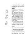
Handling. To protect against accidental splashes,
don't move batteries with the caps removed. Also, be
aware that pressure on the endwalls of plastic-cased
batteries can cause acid to spurt through the vents. For
this reason, it is recommended to use a battery carrier
to lift batteries. Be sure it grips the battery
securely. The type of carrier with teeth that bite into
the battery case works fine on old rubber case batteries,
but not on the newer plastic cases. If you lift a
battery by hand, grasp it at opposite corners.
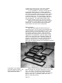
A proper battery carrier.
Explosion. Hydrogen and oxygen gases are released
during normal battery operation, particularly at the end
of the charge cycle. They are increased by rapid
charging or discharging, or by overcharging. Hydrogen
becomes explosive when it reaches a 4% concentration by
volume. It is rare for a battery to explode, but if one
does, it will scatter pieces of case and hot acid, and
may start a fire. Most batteries now come with flame
Page 16
barrier caps. However, all sources of flame and sparks
should be kept away from batteries, just as y o u w o u l d
keep them away from your gas tank.
To avoid sparks, do not break a live circuit at the
battery terminal. Instead, t h r o w the circuit breaker and
turn off the ignition key. Locate components that may
produce sparks away f r o m the batteries. Keep in mind
that hydrogen is lighter than air, and will rise. For
that reason, it is safer to locate some components below
the level of the battery tops.
Leave the battery caps on during charging, and open
the box lid or provide a fan for ventilation. If you use
a fan, be sure it has an 'anti-arc' feature. This is a
brushless fan, or one that is rated as safe for marine
bilges.
If the batteries release a strong sharp odor, this
is a warning. Turn off the charger and check it for
proper functioning. If smoke, violent gassing, or
spewing of electrolyte occurs, shut off the charger
IMMEDIATELY and check the charger and batteries for
defects.
Avoid leaning over batteries when possible. This
protects you from injury, as well as reducing the chance
that a tool may fall from your hand or pocket and short
across the battery terminals. This would melt the
tool, and could cause an explosion. If you must lean
over the batteries, cover them w i t h a fender cover,
rubber floor mat, blanket, or piece of cardboard.
Insulated battery wrenches.
It's a good idea to have a pair of dedicated battery
wrenches. One should have a box end exposed, and the
other should have an open end exposed. The rest of the
wrenches should be completely insulated, either w i t h
electrical tape or a plastic dip coating.
Containment. It is always recommended to enclose
batteries in a box. If the batteries are inside the
passenger compartment, this is absolutely required. It
is also necessary to cage and secure the batteries to
keep them from flying loose in a collision or rollover.
Page 17
We'll talk more about containment in the chapter on
battery racks and boxes.
"The final
emergency disconnect
is a good pair
of cable shears.
If all else fails,
cut a cable."
Electrical Danger
L o w Voltage System. This is the 12-volt system
that powers lights and accessories. High current caused
by a short can travel through your entire wiring s y s t e m ,
damaging wires and components and possibly causing a
fire. Always disconnect the auxiliary 12-volt battery at
the negative cable when working on the 12-volt s y s t e m .
Use good quality wire and connectors of the proper gauge,
and follow the techniques explained in the chapter on
wiring.
High Voltage System. Isolate the high voltage
system completely, so that it does not ground through the
chassis at any point. This reduces the danger of shocks,
as well as reducing the danger f r o m failures of connections or insulation.
An interlock on your charger is a good idea. This
will prevent the vehicle f r o m being driven away while
still connected to the power source.
I recommend three types of safety power disconnects,
which operate manually or automatically. All three
should be used together. The first is a main contactor.
This is an electromechanical disconnect w h i c h is operated
manually by your ignition key. This gives you a w a y to
disconnect the batteries from the drive system w h e n the
car is parked, if you suspect a problem while driving,
and during charging. It is part of the normal automotive
operating procedure that we are all familiar w i t h
already.
The second safety disconnect is a circuit breaker
between the battery pack and the main contactor, or
within the battery pack circuit. This could be used
manually as an emergency shut-off if the main contactor
failed in a closed position. It will also operate automatically in an emergency such as a motor short, or in
case of driver abuse if the car is being pushed beyond
its abilities.
The circuit breaker must be rated appropriately for
your battery pack and components. It must also be a DC
circuit breaker, not an AC breaker. The operating
characteristics of the t w o are different, and an AC
breaker might not trip at the appropriate time in an
emergency.
The third disconnect is a fusible link wired into
the circuit between t w o of the batteries in the pack. If
your battery pack is split between the front and rear of
the car, as most are, I recommend a fusible link in each
section. This is an automatic shut-off that will
function in the event of a short circuit in the pack,
which can be caused by a tool or piece of sheet metal
making contact across the terminals.
There are actually t w o other emergency disconnects.
One is a 'deadman' microswitch on the potbox w h i c h opens
the main contactor whenever the throttle is completely
released. The other is a good pair of cable shears. If
all else fails, cut a cable.
Page 18
Design & Technique
The subject of safety ranges from details like
preventing the failure of a connection to broad-scope
issues like handling, performance, and crashworthiness.
Every step of the design of the conversion, and every
technique used in building it, is integral to safety. We
will be talking about safety-related design and technique
issues throughout this book.
"Every step
of the design
of the conversion,
and every technique
used in building it,
is integral
to safety."
Safety Equipment
In any kind of vehicle, a safety kit is a good idea,
even though you will probably never need to use it. In
an EV, this should include:
1. A fire extinguisher. Be sure it is rated for
electrical fires. C 0 2 extinguishers leave no mess, but
are bulkier and more expensive than dry chemical
extinguishers. A sodium bicarbonate extinguisher is
suitable for electrical fires, and will neutralize any
acid spills as well.
2. A box of baking soda.
3. A pair of cable shears.
4. A crimper/stripper and a selection of connectors.
5. A bypass cable long enough to connect any two
batteries in your pack, in case you have to remove a bad
battery from the circuit.
6. A pair of insulated battery wrenches.
7. Extra fusible links. If you blow a fusible link
on the road, you need to find and correct the problem
that blew it. Then you need to replace the link in order
to drive home.
8. Two each 1/2" and 7/16" combination wrenches for
installing fusible links.
9. A volt/ohm meter. It should have a scale of at
least 0 - 150 volts. Very nice digital ones about the
size of a deck of cards are available for $20 - $30.
10. A flashlight.
1 1 . Flares.
Remember, safety rules only protect you if you use
them, and there is no substitute for common sense.
Page 19
4
"You do not have
the resources
to build components
comparable to
to those available
commercially,
and the potential
safety risks
cannot be justified
by the money
'saved'."
What You Need To Get Started
Space
Ideally, you would have a two-car garage or the
equivalent that you could dedicate to the project for the
duration. In real life, if you have one stall you can
take over completely, you're doing well. Many of you
will have to share a garage space with a gas car, or
other activities. This will entail a certain amount of
regular exercise as you push the donor car in and out.
Set aside an area to store the internal combustion
components until the conversion is done. Don't dispose
of anything, except possibly the engine itself. There is
a wealth of brackets and raw materials in that pile that
can be re-used in the conversion and save you hours of
fabrication.
It's helpful if you also have a single staging area
where you can lay out all the conversion parts you will
be using. You will be handling these parts many times
during the design phase, before they are actually
installed.
You will also need a work area sufficient for fabricating pieces as large as battery boxes.
Time
The amount of time you spend on the conversion will
depend on the completeness of the kit you use. On the
low end, a completely pre-fabricated bolt-in kit can be
installed by an experienced mechanic in as little as 32
hours. For the average automotive hobbyist, this might
stretch to four weekends.
For a kit in which you are responsible for component
layout, and design and fabrication of battery racks,
boxes, and miscellaneous component mounts, you should
plan on at least 200 hours. Most of that time will be
spent on design of the overall layout and specific
mounts.
Components
The following is a typical list of components for a
conversion. Trying to cut corners by eliminating any of
these is not recommended, as it will compromise performance and/or safety. I also do not recommend building any
of the components other than battery boxes and racks and
miscellaneous mounts and brackets. You do not have the
resources to build components comparable to those available commercially, and the potential safety risks cannot
be justified by the money 'saved'.
Motor
Adaptor
Controller & Potbox
Charger
Main Contactor
Circuit Breaker
Fusible Links
Ammeter & Shunt
Page 20
Voltmeter
DC/DC Converter1
Power Brake System 2
Shocks & Springs3
Clutch Parts4
Battery Racks3
Battery Box(es)3
Cable
Lugs
Batteries4
Miscellaneous Component Mounts 3
Miscellaneous Wiring 3
1
2
3
4
"When you buy
your components,
there are certain
principles
that will help insure
that you get
quality and value
for your dollar."
Optional, but highly recommended.
Only necessary if donor car had power brakes.
Will be included in bolt-in kits only. For other
kits, you will have to source these parts yourself.
Generally not included in kits.
Before we move on, I'd like to say a word about
buying kits vs. separate parts. There are several advantage to buying a kit, besides convenience. First, you
know that all the components are compatible with each
other. When buying components separately, especially
older models of components, it is possible to get combinations that will not work together.
Second, it is usually cheaper to buy a package than
to buy the same pieces separately.
Third, there are sometimes tax incentives attached
to kits that are not available for separate components.
It may be possible to get a good deal on used parts
through an electric car club. However, the buyer must
use extreme caution to be sure the parts will provide
satisfactory performance, are compatible with each other,
and represent a real cash savings after all the other
necessary parts have been collected. I do not recommend
used parts for a beginning electric vehicle enthusiast.
Suppliers
The electric vehicle industry is experiencing
another surge of interest. This means many people who
have little background in EVs are suddenly buying cars
and components, and many other people with equally little
background are suddenly selling them.
I have a unique perspective on the EV industry,
since I have been in it since 1979. I watched the spurt
of interest rise—and fall—with the last gas crisis. I
stayed in the business through the slow years of 'cheap'
gas when everyone else folded their tents and moved on.
I believed the time for EVs would come again, and stay.
Now I am watching many of the same mistakes being made
again that were made last time.
Those of us in the industry have a duty to educate
the buying public about possible pitfalls. Whenever
someone has a bad experience with an EV or an EV business, it tarnishes us all. Whether you buy your components from me at Electro Automotive or elsewhere, there
are certain principles that will help insure you get a
'good deal', meaning quality and value for your dollar.
With that in mind, I would like to offer the followPage 21
"Some hobbyists
should be declared
national treasures;
others should
be declared
national disasters.
Be sure to find out
which kind
you are dealing with.'
ing guidelines for those trying to sort through the
various claims and offers of electric vehicles and components.
Get References. Never take the w o r d of a
salesperson on its o w n merit. Check w i t h independent
knowledgeable sources in the industry, such as electric
vehicle enthusiasts' clubs or alternative energy publications. Is this person or business w e l l - k n o w n and
established within the industry? H o w long have they been
involved w i t h EVs? Are they reliable, ethical, and
competent?
Any industry in a boom phase will attract a s w a r m of
new 'businesses'. Some will be outright frauds, though
they may be extremely smooth and convinvcing. Others are
honest and sincere people w h o simply d o n ' t have the
technical or business background to deliver on their
promises. Dealing w i t h an established, reputable business will insure technical support for the components you
buy.
These are some phenomena that should be approached
w i t h caution:
The Instant Expert. Just because an EV is relatively simple, many people think no special expertise is
needed to be an expert. This person may claim to have
been in the EV business for ten years. On independent
research, however, you will find that no one in the
industry heard of him before last year. He's been 'in
business' for ten years—installing car r a d i o s — a n d he's
had an EV or t w o that he bought used and tinkered w i t h
from time to time. This person k n o w s just enough to
cause serious problems.
Rip Van Winkle. He really has been in the EV
industry since ten years ago. In fact, he's still in the
EV industry of ten years ago. His components are three
generations behind the times, and will not give satisfactory performance. Surprisingly cheap prices are often a
warning sign of this situation.
The Hobbyist. Some hobbyists are brilliant, and
should be declared national treasures; others should be
declared national disasters. Be sure to f i n d out f r o m
outside references w h i c h kind you are dealing w i t h . Also
be aware that you may end up w i t h a one-of-a-kind vehicle
that is only fully understood by its creator, and is a
mystery to everyone else. Such an orphan can be a problem if you ever need to make changes or troubleshoot a
malfunction.
Magical New Components. Someone has always 'just
come out w i t h ' a Magic Motor, a Better Battery, or some
other Holy Grail that will give amazing range and power,
weighs almost nothing, produces more p o w e r than it uses,
and cures cancer. On closer inspection, y o u will find
that these fantasy components are hand-built laboratory
prototypes. They also have a f e w little drawbacks, like
enormous price tags, 6 0 0 ° F operating temperatures, or a
tendency to self-destruct. Someday some of these fairy
tales will come true, and will benefit us all. In the
meantime, it is foolish to base your vehicle on the magic
of tomorrow. If you do, your dream coach-and-four will
remain a lumpy pumpkin pulled by w h i t e mice. Build w i t h
available technology today. You can always upgrade
later.
Page 22
"Components that
are too cheap or
too expensive
will prove to be
unsatisfactory."
In general, be realistic. An EV built with proven,
current production technology can provide completely
satisfactory performance for use as a local commute and
errand-running car. This represents the largest percentage of American daily mileage, and is the perfect niche
for the EV today. Components that are too cheap or too
expensive will prove to be unsatisfactory. Take a little
time to learn who is established, respected, and experienced in the industry, and you will be treated well.
Cost
The minimum cost for a sound conversion using new
modern components is about $5,500 - $6,000. In this
instance, you will not be using a bolt-in kit. You will
be doing the component layout design, and designing and
fabricating all the necessary battery racks, boxes, and
miscellaneous mounts. This price assumes using the least
expensive materials that are adequate for the job, such
as plywood for the boxes.
The high end cost for a basic conversion is about
$8,000 - $9,000. This is for a pre-fabricated bolt-in
kit including better quality materials such as powderpainted battery racks and welded polypropylene battery
boxes.
Your costs may fall somewhere between these two if
you use a non-bolt-in kit, but better quality materials.
You can easily spend $50,000 on a conversion if you
want to use high-tech drive systems or exotic batteries,
but this is completely unnecessary.
I should say a word here about tax incentives. I
won't get too specific, because these change from state
to state and from year to year. Simply be aware that
there may be some tax breaks to help you finance your
conversion. Contact the nearest electric car club to
find out what is currently available in your area.
For example, California passed a law effective in
1991 that established tax incentives for conversions.
(The law was cleverly given zero publicity, but we found
out about it anyway.) Basically, the law stated that a
conversion kit (if duly certified by the state) was
exempt from sales tax, and eligible for up to $1,000 in
state income tax credits. The law will lapse in 1995.
When we called the state to find out how to get our
kits certified, they couldn't answer us. No one had
bothered to figure out how to implement the bill. My
partners and I, especially Dick Rahders, spent many hours
wheedling and badgering the state into writing the procedures to implement the law. We were the first company to
get our conversion kits certified. Now, it's a simple
matter of filing a couple of forms and visiting a smog
referee to collect a tax credit.
Other states may have similar or other incentives,
including sales tax exemptions, income tax credits,
registration incentives, and even insurance subsidies.
There are also some federal incentives in place, and
others on the drawing board, but it is not clear whether
these apply to conversions by private individuals or only
fleet conversions and new vehicle purchases.
Check the current incentives in your area. If there
aren't any, call your state legislators and ask why not.
Page 23
"The factory—
repeat, factory—
manual for your
make, model and year
of car is essential
for your conversion."
Advisors
There are a few people in your town who can be
valuable advisors on this project. They include the
dealership parts man, a good aftermarket parts man, a
wrecking yard man, and a welder. They may also include a
machinist or plastic fabricator.
(And by the way, some of the best parts 'men' I have
known have been women.)
In dealing with these people, be as professional as
possible. They are often harried and overworked, and
they deal with more than their share of vague and confused customers. Always go in armed with complete information. This means, besides make and model, any special
designations ('DX' or 'GT'), body type (2-door, 4-door,
hatchback, wagon), and the Vehicle Identification Number
as extra insurance.
The engine size will be important, even though you
are throwing the engine away, because many other parts
such as brakes and suspension are keyed to the engine
size. The exact production date (month and year) can be
important, especially on Japanese cars, since there may
have been running production changes. This date can
usually be found on a metal plate somewhere on the
driver's door or door pillar. The parts men may ask
seemingly irrelevant questions, such as, "How many headlights does it have, and what shape are they?" Believe
it or not, this may help you get the right clutch parts.
The best plan is to explain your project briefly,
show them this manual, and get them personally interested
in and excited about your conversion. A bag of cookies
or a box of doughnuts can also help cement your relationship.
The dealership can help you get specific details on
your car, and identify possible useful crossovers from
other models. Some parts are available only from
dealers.
For other parts, an independent aftermarket parts
house can offer the same kind of help. Look for a store
that caters to the trade, with a lot of guys in blue
uniforms as customers. There will be at least one person
in that store with a wealth of product knowledge in his
head. Franchise stores that sell to the public usually
have staff who only know what's in their catalogs and
computers.
A wrecking yard can be a cheap source of the interchange parts that you identified with the help of your
friends at the dealership and parts house.
Welders, machinists, and plastic fabricators can
build mounts and boxes for you, but they can also assist
in the design stage by recommending types of materials,
construction techniques, and explaining the strength requirements to do the job properly.
Books
There are two books that are essential for your
conversion. The first is the factory—repeat, factory—
manual for your make, model, and year of car. This is
the same manual the dealership issues to its mechanics.
An aftermarket manual will not be specific enough,
especially for things like wiring diagrams. The factory
Page 24
"Your Project
Notebook will be
the 'factory manual'
for your conversion.'
manual will guide you through the disassembly of the
internal combustion system, provide a road map to the
existing 12-volt system, and assist you in other mechanical work, such as brakes and suspension.
The second is a Project Notebook. Use something
you're comfortable with: a spiral notebook, three-ring
binder, blank bound book, or whatever you like. Reserve
it for this project alone, and keep it where you can
always find it easily. You will need to make notes and
drawings and jot down measurements as you work on the
car. Keeping them all in one place will make it easy to
refer to them later. Be sure to label your drawings and
make your notes detailed enough that they will still make
sense to you in a couple of weeks—or a couple of years.
What you are building is the 'factory' manual for your
conversion.
A third book is highly recommended. This is Battery
Book One, written and published by Curtis Instruments,
Inc. This book will give you a detailed picture of how
lead-acid traction batteries work, and how to optimize
their performance. This book is available through
Electro Automotive.
Tools
The following is a recommended list of tools and
supplies. If you are an automotive hobbyist, you will
have most of them already. Some of the specialty tools
may be included in your kit, or may be available from
your kit supplier. Many of the tools will not be needed
if you are installing a bolt-in kit.
Large Tools
Engine hoist & sling (can be rented)
Floor jack (min. 1 112 ton rating)
Heavy duty stands
Sawhorses
Creeper
Power Tools
Electric drills <3/8" drive & 1/2" drive, with drill
index 1/16" to 1/2" by 1/64" increments, hole
saw attachments, and unibit)
Jigsaw (Milwaukee Sawzall-type tool preferred if
available, with 32-tooth metal-cutting blades)
Circular saw (with plywood blades and cutting
guide)
Hand grinder (with metal grinding wheel and sanding
disks)
Heat gun or hand-held propane torch
Hand Tools
Razor box knife
Cable crimper
Cable shears
Wire stripper & crimper
Small soldering iron
Hammer
Pliers
Combination end wrench set (8mm - 19mm metric or
3/8" - 3/4" inch, to suit your car)
3/8" drive ratchet and sockets (same metric or inch
sizes as end wrenches)
Allen sockets (3/8" drive, 5/32" & 5/16" sockets)
Page 25
Tap & die set
Assorted sizes flat & crosspoint screwdrivers
Diagonal blade wire cutters
Pry bar
Hacksaw
Coping saw
Steel measuring tape (at least 18')
Steel straightedge (48")
Metal square
Scribe or ice pick
Center punch
Punch set
Chisel set
Pop rivet tool
Torque wrench
Caulking gun
Dial caliper
Battery lifting strap
Battery wrenches (two 1/2" combination end wrenches,
all but one end on each wrapped with electrical
tape)
Miscellaneous Tools
Safety glasses or goggles
Drop light
Volt/ohm meter
Bench vise
Drain pan
C-clamps
Broad felt-tip marker
Leather gloves
Yellow tire crayon
Shop towels
Supplies
Assorted cable ties
Anti-corrosion compound (such as Noalox or CualAid)
Shrink tube
Spray carburetor cleaner
Silicone spray
Red Loctite
Moly lube
Caulk
Heatsink grease
Masking tape
Duct tape
Spray primer and paint
Mechanic's wire
Low friction synthetic transmission oil
Teflon thread-seal tape or paste
Drywall screws
Construction panel glue
Blue layout fluid
Now the stage is set. It's time to choose the donor
car.
Page 26
5
Choosing A Chassis
One does not convert a car, like climbing a mountain, just because it's there. Some vehicles make better
conversions than others. Let's start talking from the
broadest scope, and work our way down to specifics.
First, I want to limit the discussion to passenger
cars, pickup trucks, and light vans. Large and small
industrial vehicles can be converted to electrics, as can
ultralight racers, motorcycles, and bicycles. However,
all these vehicles fall outside the range of this book,
and need to be addressed separately elsewhere.
Ground-Up Design
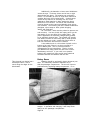
The Vortex is a car you build
from a set of plans. It's
built from the ground up, but
the design work has already
been done for you.
(Photo courtesy of Dolphin
Vehicles.)
In an ideal world, an electric car would be designed
and built from the ground up to maximize efficiency and
performance. In real life, however, this is not a practical option. The average person, even a very talented
and experienced one, does not have the expertise or
resources to design and build a complete vehicle. A
ground-up design requires not only the frame and body,
but brakes, suspension, steering, doors, headlights, and
a multitude of tiny details—all of which must meet
certain standards to be street legal. If you are an
automotive or industrial design professional, you may be
able to do it, but it will consume enormous amounts of
time and money.
Simply converting an existing car provides plenty of
opportunities for you to exercise design and fabrication
skills. Take advantage of the chassis and mechanical
design that some manufacturer has already done, and
concentrate your efforts on the conversion aspects.
Page 27
Kit Cars
If you are a very hands-on person and want a more
ambitious project—and a more unusual final product—you
can build a kit car as an electric. Their lightweight
fiberglass bodies make kit cars excellent performers as
electrics. Since you assemble the entire car from
pieces, you have the opportunity to make minor modifications to the chassis to aid in the conversion.
The Jackrabbit kit car is a
high quality kit, and can make
an excellent electric.
{Photo courtesy of Herb Adams
VSE.)
If you are interested in building a kit car, do some
serious research before buying your kit. Be sure you are
buying from an established and reputable supplier. Ask
for references from customers who have the kit you want.
Try to see a finished car in the flesh, so you can check
out the quality of the kit, and its potential as an
electric. Find a local kit car club and get advice from
more experienced builders.
Most of us will be converting existing gas or diesel
steel-bodied cars. There are several aspects of the car
to be evaluated before making a choice.
Weight
Increased weight decreases range and performance.
The same heavy cars that get poor gas mileage will make
poor electrics. Look for a car that's under 2,500 pounds
curb weight before conversion. Under 2,000 pounds would
be even better, and 3,000 pounds is the upper limit.
Remember that, even after stripping out the internal
combustion components, the car will gain 800 pounds or
more during the conversion.
The curb weight is what the car actually weighs when
it is empty. Gross vehicle weight is the maximum rated
weight, fully loaded. To check curb weight on a potential donor car, go to the library and look up Road &
Track Magazine for the year the car was built. There
will probably be a detailed report with all the relevant
specs. Consumer Reports also carries such information.
While lightweight cars are good, they may have their
Page 28
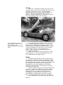
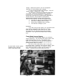
Light pickup trucks, like this
Datsun, make good conversions.
own problems. One is limited space for batteries. Even
a very light car needs a minimum of 72 volts, which means
twelve 6-volt batteries, to be marginally street safe,
and 96 volts, or sixteen batteries, is recommended.
Another potential problem is the ability of the suspension and frame to accept the added battery weight.
The ideal chassis is light but roomy, something
similar to a Rabbit, Civic, Sentra, Escort, or light
pickup truck. Beware of cars like the Fiero, that are
actually much heavier than they look.
Body Style
Look for accessible battery space. Hatchbacks are
probably the best choice. Remember that batteries can be
sunk into the floor. This means you can have batteries
and a backseat, too—and even cargo space in the
hatchback area, on top of the battery box.
Check the engine compartment for protrusions or a
low-profile nose that might interfere with battery placement.
Age
The rule of thumb here is to look for a car that is
less than ten years old, and the newer the better. There
are many reasons for this. Newer cars obviously offer
better crash protection and aerodynamics, since much
progress has been made in these areas in the past decade.
Also, availability of parts is poorer after ten years,
and drops significantly after fifteen years for many
cars. Even after the car is converted, you will still
need things like brake pads.
Condition
The ideal donor car has a good body and interior,
sound transmission, but a dead engine. For these
Page 29
reasons, cars like the diesel Rabbit make an excellent
choice. Watch the classified ads for ones that say,
"Good body, needs engine." Also, talk to local junkyards
or independent garages that specialize in the kind of
car you w a n t , and tell them to w a t c h for a good candidate
for you. Specialty mechanics may be able to recommend a
particular model of car that tends to b l o w up engines.
If at all possible, get a mechanic to check out the
donor before you buy it. You will w a n t to k n o w about the
brakes, transmission, and constant velocity joints, as
these are the most likely items that can add expense to
the project. The clutch, shocks, and springs aren't as
important, as you will be changing those a n y w a y . Be on
the lookout for any evidence of crash damage that might
have tweaked the frame. A small variation f r o m ' t r u e ' in
the chassis can sometimes drive you to distraction w h e n
you are trying to mount components to it.
If you get a donor that runs, you can recoup some of
your investment by selling the engine. This is best done
while it's still in the car and can be test driven. Be
sure the buyer k n o w s that you will be keeping some of the
parts, such as the flywheel.
Make & Model
This Rabbit is more than ten
years old, but there is still
good parts availability for it
because there were so many of
them built.
The first criterion for make and model is availability of parts. Look for a make w i t h a strong dealer
presence in your area, and a model w i t h a long production
run and a large number of them built and sold. This will
mean availability of dealer-only parts and expertise, of
aftermarket parts, and of junkyard parts. Orphans make
poor candidates for conversion, even if A u n t Minnie has
one behind the barn that she'll give you for free. However, a twenty-year-old car might still be a good candidate if it's in good condition and there is good parts
availability.
In general terms, it is harder to find a suitable
American donor than it is to find a foreign one. This is
Page 30
because American manufacturers have only recently become
interested in producing small aerodynamic cars. They are
often American in name more than content. Japanese cars
seem especially suitable for conversion.
A few cars have special idiosyncrasies. If you get
a Honda, be aware that the crankshaft rotates in the
opposite direction from almost every other car in the
world. Your electric motor supplier should be able to
adjust the motor so that it runs most efficiently in the
proper direction for your car.
Subarus and rotary Mazdas have a design that
recesses the flywheel into the back of the engine. This
requires a very thick and expensive adaptor plate for the
electric motor. For that reason, I don't recommend
them.
"Using the clutch
gives a much
smoother ride."
Transmission & Drive Axle
Conversions can be front-wheel drive or rear-wheel
drive. Having the engine and the driving wheels at the
same end of the car makes packaging easier, but isn't
essential. Four-wheel drive is not a practical option at
this time.
Automatic transmissions are also not practical for
individual conversions at this time. They can be done,
but performance is marginal and they can't really be
economically justified except for fleets. One problem
with automatics is a loss of power, which electrics can
ill afford.
Another problem is that an automatic transmission
depends on a continuously idling motor to provide fluid
pressure. Without it, there is a serious lag in acceleration from a full stop. An electric motor doesn't idle.
When the car isn't moving, neither is the motor. If you
idle the electric motor like a gas engine, you are wasting energy and defeating its efficiency. Adding a separate fluid pump adds one more component and level of
complexity to the system.
Finally, electric motors have a different torque
profile and want different shift points from those of
a combustion engine.
I wouldn't be surprised if there is a suitable automatic transmission for an electric car in the next few
years, but it isn't here yet.
We do maintain the original clutch and flywheel in
the conversion. One reason is safety. If anything
should go wrong while the car is in motion—a motor lockup or runaway, a locked-up wheeH—it is possible to disconnect the motor from the wheels using the clutch.
Another reason is comfort. Using the clutch gives a much
smoother ride.
Another drive option often suggested is direct
drive, or even a motor on each wheel. I do not recommend
either option. Direct drive can be done, but it is expensive and bulky. Without a transmission, an enormous
amount of voltage or current is needed to achieve a combination of good acceleration and highway speeds. Most
direct-drive cars use packs of more than 300 volts, which
means a lot of batteries. It also means very expensive
components, and special charging requirements.
Motors on the wheels themselves have design problems
Page 31
due to the unsprung weight of the motor. Multiple motors
need very tricky synchronization of speed controls and
steering.
Options
"A poor chassis
will give you
a poor EV."
In general, a 'Sally Rand' (stripper) version of a
car is preferable to the luxury version. Air conditioning eats almost as much horsepower as it takes to move
the car down the road. Also, air conditioning technology
is now in a state of transition, due to the CFC problems.
Probably within the next few years a new air conditioning
system will emerge that is environmentally benign, and
suitable for an electric car.
Power steering is another energy eater, but most of
the potential donor cars in a suitable weight range don't
have it anyway.
Luxury models also usually have more sound deadening, which is not necessary in an electric car.
Power brakes, on the other hand, are easily accommodated with a vacuum pump, and are highly recommended,
due to the added weight of the batteries.
Power windows and stereos don't use enough energy to
hurt anything. Enjoy.
The Right Stuff
There are three ingredients in a good electric conversion: a good chassis, the right components, and a
well-designed and carefully executed installation. Just
because a particular car is readily available or cheap
does not mean it's suitable—and a poor chassis will give
you a poor EV. Making the right choice at the beginning
will go a long way toward a satisfactory final product.
Page 32
6
Removing The Internal
Combustion System
Before you can install the electric components you
will have to remove a lot of original equipment. Which
pieces you remove—or save—and how you do it can make a
big difference in the final conversion.
When Detroit builds a car that is 70% new design and
30% off-the-shelf, it spends 3.1 million hours of engineering design time on the 70% of the car that's new.
For optimum results in your home-built electric car, it
makes sense to take advantage of as much of that
engineering as possible.
Measurements
There is one basic rule that is essential when
disassembling something that must be reassembled later:
study, measure, and mark everything BEFORE you take it
apart.
Therefore, when you are ready to start disassembling, the first things to save are measurements. With
the car parked on the level, measure the ride height at
all four wheels and record these numbers in your Project
Notebook. This is done by running a steel measuring tape
vertically from the ground, across the center of the
wheel, to the center of the wheel arch on the body.
Measure the ride height at all
four wheels before you start
stripping the car.
There will be some difference in these measurements,
front to rear and side to side. Knowing what these
differences were before conversion will let you know
whether any differences after conversion were there
originally, or introduced in the conversion process.
Incidentally, if the initial difference is greater than
2" from side to side, check for possible frame damage
from an accident.
Page 33
If the car can be driven, get it weighed—the whole
car, and each axle separately. This will help you try to
match the original weight distribution and adjust your
suspension.
The first piece to remove is the hood. Before you
do, use a scribe to trace the outline of the hinge in the
paint on the underside. This will make it easier to
reinstall the hood precisely later. A slight misalignment can cost you hours of tinkering while you try to get
the hood latch to work properly.
Before removing the engine, measure the distance
from the top of the transmission bell housing to some
mark on the firewall. If your car has a transversemounted engine, lay a flat piece of steel or wood across
the fenders at a point you can mark and duplicate later,
and measure straight down from this piece to the bell
housing.
Measure the distance from the
top of the transmission bell
housing to some stationary
mark. (It's easier to see in
this photo, with the electric
motor already in place, than in
the original car with the gas
engine.)
This measurement will help you reinstall the transmission with the electric motor in exactly the same position. This is important for such things as driveshaft
angularity and shift linkages.
Another thing to study before disassembly is the
throttle linkage. Make notes about how the pieces go
together, and measure the travel distance from full off
to full on at both the pedal and the carburetor or fuel
injection system. These measurements will be critical
when installing your electric throttle connections.
IC Component Removal
Now you are ready to start removing the internal
combustion (IC) components. Use your factory manual to
guide you through this process, incorporating the additional following instructions.
The first things to throw away are all the fluids in
the old car, except hydraulic fluids. Brown's First Law
of Conversions states that any car you choose for a donor
will have a fuel tank that's more than half full. If the
Page 34
fuel is clean and fresh, it can be used in some other \C
vehicle.
Drain the engine oil and the radiator fluid. (Note:
on the west coast, this is called 'coolant'. In the midwest and east, it is called 'antifreeze'. Same fluid.
Climate determines semantics.) The transmission oil
should be drained, too. When you reinstall the transmission, you will want to fill it with a low-friction synthetic oil.
Dispose of all the fluids carefully and properly.
This is especially important with coolant. It is sweet
and attracts small children and animals—and it is a
deadly poison.
If any of the factory manual instructions seem
strange, complicated, or require you to remove or disconnect unrelated things, check with a shop that specializes
in your make of car, and see what procedure they use.
There may be a be a better way, or a special trick. For
example, the Rabbit factory manual says to remove the
engine from the bottom of the car, but we always took it
out from the top when I worked in the dealerships.
When the engine and transmission have been removed
from the car and separated, there is one more measurement
to take. I call this the 'magic number'. This is the
distance from the rearmost surface of the engine (where
it mates to the transmission) to the rearmost flat surface on the flywheel. This may or may not be the friction surface of the flywheel. The measurement should be
accurate to three decimal places in inches.
The 'magic number' is the
distance between the rearmost
surface of the engine and the
rearmost flat surface of the
flywheel.
If there is already a pattern on file for an adaptor
for your transmission, this number is unnecessary.
However, if I have to design an adaptor, I will need this
number to determine the thickness of the hub.
As you take the donor car apart, do so with a
scalpel instead of a machete, because you might want to
graft some of those pieces back together later. Remove
all the wires at their connectors instead of cutting
them, and label them with tape and a marker. Be sure it
Page 35
is an indelible marker. Otherwise, you may steam clean
the engine bay and end up with lots of pretty little
white flags with no writing on them.
As you disconnect wires, label
them with tape and an indelible
marker.
Save all the original nuts and bolts in baggies, and
label what they came from. These may allow you to re-use
original holes or brackets.
It is generally easier to remove both the engine and
transmission, then reinstall the transmission later with
the electric motor mounted to it. You may think it's
less work to leave the transmission in the car, but it
actually makes your job harder.
There are two metal tabs on the engine that are
specifically for lifting it with an engine hoist. Save
those tabs and adapt them to your electric motor, adaptor, and transmission when it is time to sling them into
place.
Even if you are replacing the clutch, save the old
parts until you are sure the new ones match. Save the
flywheel and all the bolts associated with it, because
you will want to re-use them with your adaptor. These
are special bolts, and will cost you time and money if
you have to special-order them through the dealer. Also
save any locating dowels between the engine and transmission.
Remove everything associated with the IC system:
radiator, fuel system, exhaust, etc. You will want to
use a 12-volt accessory battery, but not the original
one. If you do not have a DC/DC converter, you will want
to replace the original battery with a heavy-duty deep
cycle battery, especially if you do much night driving.
The DC/DC converter is highly recommended as a constant
source of voltage for lights, etc., but it doesn't replace the battery. If the DC/DC should fail for some
reason, it will do it at night ten miles from home. So
if you do have a DC/DC, you will still want a 12-volt
battery, but you can use a very small one.
Don't plan to eliminate the 12-volt battery by
tapping across two of your main pack batteries for
Page 36
accessories. This will cause uneven discharge of the
pack, and shorten its lifespan. It also violates the
rule about isolating the traction batteries from the
auxiliary battery and chassis.
When the car is apart, this is the time to inspect
things like constant velocity joints and boots, and
replace them if necessary. This is also the time to
steam clean the engine bay in preparation for installing
the nice clean electric components.
As you disassemble your donor car, take notes on
anything you may need to reassemble later. Use your
Project Notebook for sketches and diagrams. Maybe you'll
want to take photos or videos. Use whatever method works
best for you, but document everything.
The building of the electric conversion actually
begins with the dismantling of the internal combustion
car. If it's done right, the process of disassembly is
an integral part of the process of assembly. It should
be done thoughtfully, with the vision of the finished
conversion always in mind.
Page 37
7
Installing The Motor
& Adaptor
The motor is the center of the electric car's
universe. It is the first component you need to install.
It has a pre-determined position in the center of the
engine compartment, and all other components must fit in
around it. The type of motor you use will determine what
other components you use, and what performance you will
get. It is not the place to skimp.
Motor Types
The series brush DC motor is
the favorite for conversions.
In the rugged early days of the modern electric car
(meaning the late 1970's), the aircraft generator or
starter was the most common motor used simply because
there were few other options readily available. It made
a great aircraft generator, but a very marginal electric
car motor. It was rated at 24 volts, but for automotive
use it was run at 48 to 72 volts. Not surprisingly, the
generator often refused to take such abuse and died.
Also, the rpm band of the generator was not suitable for
a car, causing it to suck up great rivers of amperage,
which translated to a short driving range.
These generators are still emerging from basements
with 'For Sale' signs, but they are less appropriate than
ever. For one thing, the shaft has a 16-tooth spline
that's very expensive to mate to an adaptor. For another
thing, they are incompatible with modern controllers.
Another motor of yesteryear was the Baldor. These
had a disturbing habit of spontaneously disassembling
themselves.
An interim motor of the mid-1980's was the China
Motor. Designed as an improved version of a aircraft
generator, it operated well at 72 volts, but not higher,
and it had the same spline problem.
Page 38
"A chain is only
as strong as
its weakest link,
and so it is
with an electric car's
drivetrain."
The motor of choice for the hobbyist today is the
series DC motor. The most popular line is manufactured
by Advanced D.C. Motors, Inc. It is efficient, reliable,
readily available from various distributors, affordable,
and most important, it is designed to be an electric car
motor. This motor dominated the 1992 Solar & Electric
5 0 0 race in Phoenix.
Other usable motors are the Prestolite and G.E. The
Prestolite is the forerunner of the Advanced D.C. motor.
It is a little larger, heavier, less efficient, and less
well ventilated, but if cost is a factor and a used
Prestolite is available, it will serve you well. This
motor is no longer in production.
The G.E. motor [not the same as a G.E. aircraft
generator!) is also adequate, and has approximately the
same slight drawbacks as the Prestolite. If you are
buying a used G.E. motor, be sure to check the rpm
rating. It should be 5 1 0 0 . There are still some in
circulation that are only rated at 2 3 0 0 rpm. They have
lots of torque, but no top end speed.
What about other types of motors: shunt, c o m p o u n d ,
permanent magnet, brushless DC, or AC? All of these
suffer from limited or non-existent availability in sizes
suitable for cars. Shunt and compound motors have less
acceleration than series motors, and permanent magnet
motors have a narrower rpm band of efficiency. This
means that they are most efficient at a constant speed.
This makes them perfect for something like an ultralight
cross-country solar racer, w h i c h maintains a steady pace.
In normal driving, however, speed varies greatly. Permanent magnet motors are least efficient at the l o w rpm
used most in stop-and-go driving.
Brushless DC and AC motors are available primarily
from a company called Solectria in Massachusetts. While
they are slightly more efficient than series m o t o r s ,
their control systems are much more expensive. They are
good equipment, but are generally used only in production
and race cars, and very high-end hobbyist cars.
Then there are the various exotics. These are at
the opposite end of the spectrum from aircraft generators. Most of these are the unproven dreams of t o m o r r o w .
They are laboratory animals, available only as hand-built
test prototypes. They are still being debugged, and are
not commercially available in regular production. Eventually, some of them will certainly mature into valuable
EV components, and you can always upgrade to t h e m .
Until then, don't design your electric car around something that is still a pipedream.
If you are converting a Honda, be sure to inform
your supplier when you buy your motor. Honda engines
rotate in the opposite direction from everything else.
Some motors can run in either direction. On the Advanced
D.C. motor, the supplier can make an adjustment so that
the motor will be most efficient in the right direction.
Some motors will not w o r k in this reverse application.
Adaptors
Once you have your motor, you need to install it in
the car. The first step is attaching it to the transmission w i t h an adaptor.
Page 39
A chain is only as strong as its weakest link, and
so it is with an electric car's drivetrain. All of the
horsepower and torque needed to move the car down the
road must pass through the adaptor on its way to the
transmission and wheels. This, like the motor, is no
place for half measures.
The adaptor needs to be designed, machined, and
installed precisely. This does not mean laying the
transmission face-down on a piece of cardboard and
tracing the outline and holes with a pencil to make a
pattern. A professional adaptor manufacturer will
measure and machine each bolt or dowel hole, as well as
the thickness of the plate itself, to be accurate within
a few thousands of an inch. This kind of accuracy
assures a secure fit between motor, adaptor, and transmission. Any sloppiness in fit will eventually cause
poor performance and could damage the motor or transmission.
Okay, let's look at what an adaptor is. There are
two sections to an adaptor: the plate that mounts the
motor to the periphery of the transmission, and the hub
that connects the motor shaft to the flywheel and
physically transmits the power. The plate can be made of
aluminum in order to save weight. It should be no less
than 5/8" thick for adequate rigidity.
The plate may actually come in two parts, as long as
they are precision machined to fit together. At Electro
Automotive, we use a 5/8" thick transmission profile
plate and a motor ring that varies from 5/8" to 2 3/4" in
thickness.
MOTOR RING
This diagram shows an exploded
view of an adaptor using a
two-part plate and a two-part
taperlock hub.
TRANSMISSION PROFILE PLATEThere are two reasons for this design. The first is
weight and economy. The minimum thickness needed for the
plate is determined by the space needed for the hub. If
the profile plate were this thick, it would be very heavy
and expensive. The ring, which is the diameter of the
motor rather than of the transmission, is much more light
and affordable.
Page 40
The second reason is that it allows the car to be
upgraded to a newer or larger motor by simply changing
the ring, instead of the entire adaptor.
The other section of the adaptor is the hub. This
connects the motor shaft to the flywheel. This must be
made of steel, not aluminum. The motor shaft has a
square steel key in it that fits into a slot in the hub.
If the hub is soft aluminum, that steel key will eventually 'egg out' the slot and start cutting into the hub
like a machine tool bit. This is not a pretty sight,
especially at 50 mph.
An adaptor, showing the transmission profile plate, the
motor ring, the motor shaft
bushing, and the hub.
There are several styles of adaptor hubs. Most of
them are problems waiting for the worst possible time to
happen. All the power of that motor passes through this
little hub the size of a hockey puck. This, also, is not
a place to skimp.
One style holds itself in place with a setscrew
through the side of the hub. Another uses a flat washer
and a bolt in the end of the crankshaft. These both have
the same problem: threads loosen. It doesn't matter how
much Loctite you use. It will eventually work loose, and
you'll be a pedestrian.
A third style is the shrink fit. In this type, the
hub is heated very hot, then slipped over the shaft and
allowed to cool and shrink into place. This will give a
good, secure connection. Unfortunately, it's too secure.
If you ever need to remove that hub, you've got a problem.
The last style is a taperlock. This, like the
plate, comes in two pieces. One is a cone-shaped bushing
that slides over the motor shaft. It also slides inside
the second piece, a hub that mounts to the original
flywheel. The cone has a slit through it, and starts out
a little bigger than the hole it fits into, so it won't
go in all the way. As screws are tightened to pull it
in, it compresses the slit and squeezes the motor shaft.
It's easy to install, but once it's in place, the only
way it will come off is with a special pulling tool.
Page 41
Measuring the 'magic number'
w h e n installing the adaptor
This taperlock style of hub is the most secure for
an electric vehicle, and is the standard for high-torque
high-rpm industrial power shaft connections.
There are some numbers that need special attention
here. The first is t h e ' m a g i c number'. On the gas or
diesel car, this is the distance between the back of the
motor and the rearmost flat surface of the f l y w h e e l .
This distance needs to be duplicated when installing the
flywheel on the electric motor.
A motor secured to t h e
w o r k b e n c h w i t h a chain,
eyebolts, and turnbuckle.
The second number is a measurement of torque. The
hub is attached to the flywheel using the original bolts.
These are special hardened bolts. When installing t h e m ,
use a torque wrench and the torque numbers in the manufacturer's service manual.
Page 42
In order to get the leverage you will need to
tighten these bolts, the electric motor needs to be
immobilized. One way to do that is by using one or two
very muscular friends. A better way is to strap the
motor to the workbench. This can be done by installing
sturdy eyebolts in the workbench on either side of the
motor. Then pad the top of the motor with shop towels,
and run a length of chain between the eyebolts and across
the motor. Tighten the chain with a turnbuckle until the
motor doesn't move. Also, use a steel anti-rotation
strap attached to mounting holes in the commutator end of
the motor.
An anti-rotation strap installed on a motor for bench
work.
Any time you are tightening a circular pattern of
bolts, make several passes over the entire sequence, and
use a criss-cross pattern. That is, don't try to tighten
one bolt all the way, then the one next to it, and so on.
This will cause the piece you are installing to tilt
slightly, and you will not get a proper tight fit when
you are finished. You may even damage threads.
When tightening bolts in a
circle, use a criss-cross
pattern, tightening each bolt a
little bit, and making several
passes over the whole pattern.
Page 43
Instead, tighten one bolt by just a couple of turns,
then move to a bolt across the circle from it, then
across again to a new bolt. Tighten each one only a
little bit each time, and make several complete passes
until all bolts are adequately tight. Use a consistent
pattern to be sure you aren't missing any of the bolts.
Flywheel & Clutch
We discussed earlier why we still use a transmission
and clutch. Now let's talk a little about the flywheel.
The flywheel has a safety function. If you were to
over-rev the motor with no load (flooring the throttle
with the car out of gear, for example), the motor could
'run away' and self-destruct. The flywheel provides just
enough load to help protect against that.
Some people suggest lightening the flywheel to
improve drivetrain efficiency. There is some advantage
to this. The most benefit would come from removing the
ring gear, which is no longer needed. The spinning
flywheel teeth actually create some drag through air
turbulence. This modification is not really necessary
for the average conversion, though. It's something for
electric vehicle hot-rodders to play with, since they
don't have carburetors anymore.
There are some reasons not to alter the flywheel.
Too much lightening will dangerously weaken the flywheel.
Also, it may be impossible to find a local machine shop
capable of doing this specialized work.
If there is a hot-rodders' machine shop in your
area, there is one trick I would recommend. Have the
flywheel and clutch balanced together. This will give
you smoother performance.
Clutch parts being mounted on
the motor and adaptor. (Note
flywheel lock tool at top, and
paint mark for aligning flywheel and pressure plate.)
The flywheel is part of the clutch assembly. When
you are installing the adaptor, this is the time to
replace the clutch pressure plate, disc, and release
bearing with new parts. If you do it right the first
time, you won't have to change the clutch again until you
Page 44
replace the motor brushes at 80,000 miles.
Motor Mounts
Now it's time to install the entire motor/adaptor/
transmission assembly in the car. When you disassembled
the car, you took some measurements to lock in the
original position of the transmission. You want to
duplicate that position when you install the electric
motor. This is essential for proper shift linkage and
driveshaft angularity, among other things. Any change in
the position of the transmission will impair smooth
efficient performance.
Motor/adaptor/transmission
assembly ready to be installed
in the car.
In order to do this, you will need to design your
motor mount precisely. In most air-cooled Volkswagens,
no motor mount is necessary. The electric motor hangs
off the transmission, just like the original gas engine
did. For all other cars, read on.
Use a floor jack to raise the assembly until the
transmission is back in its original position, as verified by the measurement you took from the top of the bell
housing. Now design your motor mount to fill that space
between the motor and the chassis.
You can make a mock-up of a motor mount from
cardboard or foamcore. Make your mock-up with the same
precision you would use for the real thing. When you
think you have something that will work, take your mockup to a welder for fabrication. (Better yet, see if you
can get him to visit your garage and look at the mock-up
in place.) Solicit his advice on any reinforcing straps
or gussets.
As with any other metal mounts, the finished piece
should get several coats of a good corrosion-resistant
paint as a minimum.
There are two types of common motor mounts. One is
a cradle that supports the motor around the middle, with
a strap over the top. This is appropriate for a car with
an in-line engine. This type of mount arrangement also
Page 45
requires a torque rod to brace the motor against spinning
in its cradle.
Try to use the original chassis motor m o u n t
brackets. If their placement would cause t h e cradle to
interfere with terminals on the motor, it is possible to
build small offset plates to go between the chassis
brackets and the cradle, in order to shift the cradle
forward or back to a better position. It may be necessary to install a support member either above or below
the motor to serve as anchor for the cradle.
A cradle-type mount, mounted to
original (black) motor mounts,
and (grey) setback plates.
For a transverse engine car, use a plate mounted to
the anti-drive end of the motor and extending into a
mounting bracket.
A mount for a transverse
motor.
There may be some bolt heads exposed on the case of
the motor. DO NOT loosen these or in any w a y t r y to use
Page 46
them for your mount. They hold the field coils in place
inside the motor, and they are installed at a specified
torque. Loosening them will cause damage to the motor.
The original motor mounts are 'metalastic' pieces.
That is, they have a rubber part bonded to a metal frame.
This is great for reducing vibration and noise, so you
should use the same technology. Design your mount to
attach to these mounts. If the original mounts aren't
too misshapen, use them for your design phase, then buy
new ones for the actual installation. If the original
style of mount won't work, try to find another style from
a different model of car at your auto parts store.
Keep the motor commutator covered with a cloth or
masking tape while you are working on the car, to prevent
any tiny chips or debris from falling into it and damaging it. During driving, normal road splash will not be a
problem, but you shouldn't try to ford any puddles that
might actually immerse the motor. A small amount of
belly shielding is recommended, expecially in areas where
roads are salted or gravelly.
Be sure the shielding does not obstruct airflow for
cooling. If it does, duct air from another area to the
motor. Prestolite and G.E. motors should have an
external cooling fan. This is not necessary on the
Advanced D.C. motor.
Torque Rods
A Honda torque rod modified for
use in an EV
We mentioned a torque rod earlier. A cradle-type
mount circles the motor but does not actually bolt to it.
Under power, the motor will try to rotate in place. A
torque rod is needed to counter this force.
The easiest way to build a torque rod is to adapt
one that someone else already produces. A Honda torque
rod is good. This is a dogbone-shaped piece: a straight
rod with two rounded ends with bushings in them. The
larger end can be unscrewed.
Install the torque rod between the chassis and the
Page 47
nearest bolt hole on the motor-side t o p edge of the
adaptor. Locate the torque rod so that it will not
interfere w i t h anything else. Build a U-shaped bracket
to allow you to bolt the small end of the torque rod to
the chassis.
Unscrew and remove the large end of the torque rod
and replace it w i t h a bolt w i t h a nut on it. Build an Lshaped bracket to connect that bolt to the bolt on the
motor adaptor. The bracket should go between the bolt
head and the nut. You can adjust the length of the
torque rod by adjusting the bolt in the threaded end of
it. Lock it by tightening the nut against the bracket.
Once the motor is installed, it's time to move on to
batteries.
Page 48
8
Batteries & Containment
One of the biggest components in an electric car is
the battery pack, in many senses of the word 'big'. It
is the bulkiest and heaviest component. It is one of the
most expensive. And it is one of the most important to
performance.
Which Kind Of Battery?
Designing the battery pack involves a series of
decisions. The first decision is which kind of battery
to use. If you study the literature about EV batteries,
you may feel overwhelmed by myriad possibilities. In
reality, though, the choices are not that broad.
The 'miracle' batteries that receive so much attention—sodium sulphur, lithium polymer, nickel iron,
etc.—are simply not commercially available to individuals. They may be planned for production for manufacturers only, or available only as laboratory test prototypes, or they may be nothing more than computer projections—vaporware. The same thing is true of fuel cells,
such as hydrogen or zinc air.
Therefore, the first question to ask about any type
of battery is, "Where can I buy one?" The answer for
most of the exotics will be, "Nowhere—they aren't available yet."
The second question to ask is, "How much will it
cost?" Some batteries are available—like nickel cadmium, or silver zinc—but only at costs equaling or
exceeding the entire rest of your conversion expenses.
If you are planning to build a dedicated race car, batteries with a high price or limited lifespan may be worth
it for superior performance on the track, but they don't
make sense for a daily driver.
Unless you have special contacts or a lot of money,
the answers to these first two questions will probably
narrow the field to conventional lead-acid batteries.
Performance Characteristics
"An EV needs
a deep cycle
battery."
The third, and most complicated, question to ask is,
"Are the performance characteristics of the battery wellmatched to the needs of an EV?" This question has several different aspects. The shape, number, and spacing
of plates, composition and thickness of lead paste, and
the ratio of electrolyte to paste are all critical items
that vary depending on the intended use of the battery.
For example, the normal battery used in a gas car is
a starting battery. It is intended to supply high current for a very short time—just long enough to start the
engine. It is discharged by a small percentage, then
immediately recharged by the alternator. It is never
intended to be deeply discharged, and especially not
repeatedly. As many of us have found out, a starting
battery that is run 'dead' too often, perhaps by leaving
the lights on accidentally, will soon refuse to revive.
An EV needs a deep cycle battery. This means it can
be discharged to 80% of its capacity and recharged
Page 49
repeatedly. Conventional starting batteries and other
non-deep cycle batteries such as gel cells can provide
high short-term performance for a race car, but not
continuous daily use.
Traction Batteries
Not all deep cycle batteries are appropriate.
Marine batteries or standby power batteries are not
intended to handle the occasional brief current peaks
a car requires. They will not provide as much range or
cycle life as a true 'traction' battery.
A traction battery is designed for high current
draws and repeated deep discharges, both of which are
needed to move a vehicle down the road. The type of battery most commonly used in EVs is a golf car battery: a
6-volt deep cycle battery, typically rated at 220 - 240
amp/hours. This is an excellent choice because it is
well-developed, very available, and affordable.
Lead-acid batteries: the new
12-volt traction battery, and
the conventional 6-volt golf
car battery.
There is also now a true traction 12-volt battery
available from U.S. Battery. This is the model 1450,
which can be ordered through U.S. Battery or Interstate
dealers. While this battery is too new to have full
life-cycle testimonials from EV owners, it was developed
by a company with an excellent record of producing quality batteries suited to EVs. The 1450 would be highly
recommended for very small cars where space is limited,
and may well eventually take over the market for larger
conversions as well.
Ni-Cads
Nickel cadmium batteries are probably the second
most common in EVs, far behind lead-acid. There are
several drawbacks to ni-cads. One is high cost, even for
reconditioned batteries. Another is low energy density.
It is necessary to have several strings of ni-cads in
parallel to have sufficient amperage capacity for accelPage 50
eration. This means a lot of space filled by batteries.
A third problem is that ni-cads come in 1.2-volt cells,
which require many more interconnects—and potential
failure points—than golf car batteries.
For most people, the conventional 6-volt lead-acid
deep cycle golf car battery is the optimum choice today.
If a better battery becomes available next year, you can
always upgrade to it.
Post Styles
Automotive style battery post.
Universal style battery post.
'L' style battery post.
There are three common battery post styles. The
first is the automotive style we all recognize from our
gas cars. This is a large round stud, which is gripped
around the outside by the cable end. These provide good
surface contact area, but the cable ends are bulky and
expensive.
The second type, called the universal style, is most
common because it is popular in golf cars. This is just
like the the automotive style, with the addition of a
threaded steel stud sticking up out of the center of the
post. It is connected by placing a lug on the end of the
cable, and fitting the lug over the steel stud and holding it in place with a nut.
This is the worst possible style. Its failings are
not as critical on a low voltage golf car, but can be
disastrous in a full passenger car. First, the top of
the post offers a small contact surface area. Second,
the post is subject to 'cold creep'. This is the process
by which lead will flow at room temperature while under
pressure. The pressure of the nut will cause the steel
stud to loosen and creep upward inside the lead post. If
the loose connection is not found, it will cause resistance. Resistance generates heat, which can melt the
lead post and start a fire.
If you are careful to tighten the connection often,
then the steel stud will simply work its way up until it
comes all the way out of the post.
The preferred style is the 'L' terminal. This is an
L-shaped post with a flat vertical tang, which has a hole
in it. It provides good contact surface area for lugs.
When we get to the wiring section, we'll discuss techniques for making snug connections that won't loosen
under cold creep.
H o w Many?
Once you know what kind of battery to use, the next
decision is how many. In simple terms, amps equal torque
and volts equal speed. However, you can't simply add as
many batteries as you want. Each one is the size of a
toaster and weighs close to 70 pounds.
Early EVs often ran 48-volt systems. The industry
is still trying to live down the poor performance they
had. A 72-volt system is the bare minimum for a roadgoing passenger car. This will give performance comparable to that of the original gas-powered 1200 CC VW Bugs.
It will only be adequate for a very lightweight car that
is never intended to be driven at highways speeds.
As we noted earlier, most conversions have a 96-volt
system, which means sixteen 6-volt batteries. This seems
Page 51
to be the optimum weight/power balance. A typical steelbodied conversion will have a range of 60 - 80 miles in
average commute conditions: mostly flat roads, some
freeway time, some stop-and-go in-town traffic. It will
have a top speed of about 60 mph. Some of the more aerodynamic cars will do better. A lighter weight fiberglass
car will have a range of 80 - 100 miles on a charge and
a top speed of about 90 mph.
If there is room for the batteries, the system can
go as high as 120 volts. In fact, this is recommended
for pickup trucks, where some payload capacity is desirable. Very soon there will be chargers and controllers
available for systems up to 144 volts. However, the advantages of the extra voltage will have to be w e i g h e d —
literally—against the expense, bulk, and weight of the
extra batteries.
When To Buy Batteries
Although you have chosen the batteries you will use
and decided how many you want, don't buy them until you
are ready to install them. Get precise dimensions and
use cardboard or foamcore mock-ups for designing your
car. That way the batteries won't be going stale sitting
on your garage floor for weeks or months—and you won't
be tripping over them.
Single Or Split Packs
The Voltsrabbit™ has a typical split pack, with eight batteries under the hood in a
split-level arrangement, and
eight behind the back seat.
One of the first design decisions in converting a
car to electricity has to be where to put the batteries.
In a typical car, there are sixteen to twenty of them.
All other design decisions will depend on where the
batteries are placed, and how they are oriented. The
obvious consideration is available space, but other
important factors include weight distribution and current
path.
Page 52
A rear battery rack recessed
into the floor behind the back
seat.
For stability and handling, the ideal arrangement
would be to have all the batteries in a single block,
between the axles. This can be done in a van by sinking
them into the floor or building a false floor above them.
In a pickup truck, the batteries can ride in the bed, but
a better plan is to tilt the bed and install the batteries underneath it. This gives good handling and also
maintains cargo space. Some of the batteries may be
placed under the hood as well.
In a passenger car, the batteries almost always end
up split between the front and rear of the car. Weight
should be kept inboard of the axles as much as possible,
and balanced between the front and rear. If either end
is significantly heavier, handling will be poor. The
weight should also be kept as close to the ground as
possible for a stable center of gravity.
In the engine compartment, it makes more sense to
keep the batteries grouped together as much as possible
in the large open center area and distribute the components around the periphery, than the other way around.
This arrangement makes it much easier to design the
racks, boxes, and wiring.
It is perfectly acceptable to cut into a chassis to
sink the batteries, if it is done with proper care. No
structural members should be cut or weakened. Any time
you cut into sheet metal, it should be primered and
painted to protect it against rust.
The batteries should be enclosed in a sturdy welded
rack. This will reinforce any area where the chassis was
cut. Care needs to be taken to insure that the batteries
do not interfere with axles, suspension, etc., and that
they do not extend downward far enough to diminish road
clearance. Once the batteries are installed, use caulk
or duct tape to seal openings between the rack, box, and
chassis to restore weatherproofing and reduce road and
wind noise.
Accessibility is also a consideration in battery
placement. You will want to be able to get to the batPage 53
teries fairly easily to inspect the terminals and connections and check the water levels. For this reason, you
don't want to stack batteries on top of each other.
Current Path Layout
"Try to keep
interconnects and
cable runs
as short as
possible."
Once you have a general idea of how you would like
to place the batteries, you need to lay out the circuit
path and get the positive and negative terminals oriented
correctly. On the next page is a sample battery layout
diagram from the Voltsrabbit™.
Following that are two pages of 'tools' for you to
use. These are scale drawings of the U.S. Battery model
2300 6-volt and model 1450 12-volt batteries. Photocopy
the page that matches the batteries you are using, and
cut them out. Coat the back of each battery with
Dennison 'Tack A Note' adhesive. This will allow you to
stick them into a battery box drawn on a piece of paper
according to the layout you have planned. Then you can
take them off, rotate them, and stick them back on until
you get the right orientation.
The 'most positive' cable out of the pack will connect the main contactor to the positive terminal of the
battery you declare to be first in the string. The batteries are then connected in series, positive to negative, like a daisy chain. If the pack is split in two or
more locations, the last negative terminal of one location will be connected by cable to the first positive
terminal of the next location. Finally, the 'most negative' cable will come from the last negative terminal in
the entire series and go to the speed controller.
Check your intended layout. Are any of the interconnects long or awkward? Do any of them interfere with
each other, or with the battery caps? (Note: find out in
advance what style caps your batteries will have.) Do
the most negative and most positive cables come out of
the circuit anywhere near the contactor and controller?
Try to keep interconnects and cable runs as short as
possible, although sometimes long runs can't be helped.
Avoid complicated or criss-crossing interconnects. With
these thoughts in mind, re-examine your layout, and see
if turning some of the batteries 180° will simplify the
circuit. If not, maybe turning some of them 9 0 ° into a
slightly different configuration will help.
Component Locations
Obviously, you will be deciding the locations of
some of your components in the course of designing your
battery layout. As mentioned earlier, you need to know
where your controller and main contactor will be in order
to plan the battery connections to them. It is more
important for them to be close to each other and to the
motor, than to be close to the cables from the battery
pack.
Circuit breaker placement is also a factor.
Ideally, the circuit breaker interrupts the most positive
cable between the batteries and the main contactor. If
this is not practical, it can be placed between any two
batteries in the series. It's best to locate the circuit
breaker within easy reach of the driver. If it is
Page 54
Voltsrabbit™ Battery Layout Diagram
FUSE-
-FUSE
MOST
MOST-
FRONT OF CAR
Page 55
6-Volt Battery Layout Dummies
U.S. Battery Model #2300
Page 56
12-Volt Battery Layout Dummies
U.S. Battery Model #1450
Bold lines indicate raised areas of the plastic battery case that might interfere with interconnects.
Page 57
located away from the driver, some kind of reliable
remote method of flipping the switch is needed.
In our Voltsrabbit™, it worked out that eight batteries fitted under the hood in a strange, split-level
arrangement, and eight fitted in a box behind the back
seat. The most positive cable ran from the main contactor under the hood, to the circuit breaker in the dash,
to the rear battery box. The most negative cable from
the rear box connected to a positive battery terminal in
the front batteries. The most negative cable of the
overall pack emerged in the front, near the controller.
When you are running cables fore and aft like this,
it is advisable to run both positive and negative cables
side by side. This will diminish electrical noise that
could interfere with some of the components.
Battery Racks
Once you have juggled all these factors into a
satisfactory layout, you are ready to start designing the
racks and boxes to secure these batteries in place. All
batteries should be secured adequately to stay in place,
even during a collision or rollover. Don't be fooled
into thinking their weight alone will hold them in place.
Department of Transportation crash test tapes of early
electric cars show poorly secured batteries sailing into
the air in 30 mph barrier tests. Watching batteries fly
forward in slow motion to crush the crash test dummy
against the steering wheel is a sobering experience.
Other cars with better placement and containment suffered
little battery movement.
Voltsrabbit™ front battery
rack and holddown frames. The
frames are held in place with
long stainless steel bolts.
Battery racks should be made of welded steel angle
stock and straps with minimum dimensions of 3/16" thick
and 1 1/2" wide (or a material of equivalent strength).
If the rack is large, use reinforcing straps across the
bottom. If you are not trained as a welder, hire someone
else to do the work. Your battery racks are not the
place for on-the-job training.
Page 58
Additionally, the batteries or boxes need holddowns
across the tops. For boxes, these can be bars or rigid
straps bolted into place. For batteries not enclosed in
boxes, it is necessary to have an angle-stock frame that
encloses their tops and is bolted down. A simple strap
across the top without an enclosing box will not be
adequate to keep batteries in place against the sharp
lateral force of a collision. Of course, the holddowns
must be placed so they cannot accidentally short across
two terminals. The following are NOT suitable holddowns:
plexiglass, nylon straps or belts, plastic shipping
straps, and ready-bolt.
As a minimum, racks must be painted to prevent rust
and corrosion. You can do this with spray paint, but the
best option (if you can afford it) is powder paint. This
paint is applied as an electrically charged spray powder
to an oppositely charged part. The powder will actually
flow around corners to coat evenly and fill small spaces.
It is then baked to a tough, ceramic-like finish which is
both non-conductive and corrosion resistant.
A nice added touch is a thin sheet of plastic on the
bottom of the rack (if there is no box) covered by a
layer of Battery Mat. This is a felt-like material
impregnated with acid neutralizers. Placing it under
your batteries will help protect the rack from accumulated battery acid mist. If your rack is not powderpainted, this material will also provide some electrical
insulation between the batteries and the rack.
Battery Boxes
This plywood box design has a
multi-layer bottom, with a
notch along the edges for the
side boards.
Batteries should be enclosed in boxes whenever possible. It is absolutely essential if batteries are inside the passenger compartment. The box will improve
performance by regulating battery temperature. In an
accident, it will protect both the batteries and the passengers. In operation and charging, it will keep fumes
away from the passenger compartment.
Page 59
"Batteries
should be
held down
inside the box
as well."
For economy, the box can be made of plywood and then
painted. Plywood is readily available and easy to work.
The recommended thickness is 5/8", and 1/2" is the absolute minimum. Plywood can be assembled using construction cement followed by sheetrock screws. A good technique to use with sheetrock screws involves two drills.
Use the first to drill pilot holes, and the second to install the screws with a screwdriver bit.
From your battery box design, make a list of each
plywood piece needed, its thickness, and dimensions. Now
make a scale drawing of a full 4' x 8' sheet of plywood,
and mark off the pieces you need, in scale. Remember
that you will lose about 1 /8" with each cut of the plywood due to the width of the cut itself. Do your layout
starting with the biggest pieces first, and work down to
the smallest pieces, in order to reduce waste. From this
drawing, you can determine how much of each thickness of
plywood you will need.
Mark each piece on the plywood just before you cut
it, according to your drawing, using a felt pen, a
square, and a straightedge. Always measure from a factory edge of the board, not a cut edge. If possible, cut
your pieces with a table saw, using a plywood blade. If
you don't have access to a table saw, use a circular saw
with a plywood blade and a plywood cutting guide.
Label each piece immediately on the rough side,
which will be the inside. Use a ballpoint pen or pencil
here, as a felt tip may bleed through your paint later.
Labels should be detailed, like 'rear box, bottom side,
this edge front'. In a layered construction, you may
also need to include 'bottom layer'.
As you assemble the box, apply construction panel
glue to each contact surface and have an assistant hold
the board in place. Check for true corners with a square
and then screw the boards together.
Plan to take the finished boxes to a packing and
moving company and have them banded with steel packing
straps at two levels for reinforcement. There are plastic corner protectors that can be placed between the
bands and the box to prevent the straps from cutting into
the wood.
As with battery rack paint, there is a better but
pricier option: welded polypropylene. This material is
stronger than plywood, so you can use as little as 1 / 4 "
thickness with proper rack support under and around it.
It doesn't need to be painted, and is acid-proof. (In
fact, it is used industrially for acid bath tanks.) It
is lightweight, and makes an attractive package. You can
get these boxes made at a plastic fabrication shop.
Batteries should be held down inside the boxes as
well. If you hit a bump at speed, they can fly up
against the box lid. To prevent this, attach small
blocks to the lid at the corners of the batteries. When
the lid is closed and strapped down, the blocks will hold
the batteries down inside the box.
The box itself can be bolted to the rack beneath it
using large carriage head bolts, which are recessed into
the bottom of the box so they don't interefere with the
batteries. This is not recommended for 1 / 4 " thick
plastic boxes, and should not be considered a substitute
for holddown straps across the top of the box.
Page 60
A polypropylene battery box.
Note holddown straps.
A two-layer battery box bottom,
with insulation.
Insulation, Heating, & Ventilation
In colder climates, it is recommended to insulate or
heat battery boxes. Insulation can be done with 1/2"
sheets of polyurethane foam inside the box. Do not use
styrofoam, as it reacts badly with battery acid. If
space permits, insulation can be built into the battery
box floor and lid as well. There are battery heating
blankets (available for use in large diesel trucks) that
can be adapted to a battery box and plugged in like a
block heater. Be careful that any heating system does
not harm plastic components, or the Battery Mat.
Insulation can be simply a second layer between the
box and batteries, or it can be a third layer in the middle of a 'sandwich' box wall or floor. In the two-layer
Page 61
version, it will be necessary to have supporting strips
of plastic or wood secured to the box bottom around the
edges and at intervals across the middle. These strips
will support the actual weight of the batteries, and the
insulation will fit in the spaces between strips.
The three-layer sandwich will only be possible in
larger conversions where there is plenty of room. This
will require a plywood bottom layer, an insulating layer
with supports as described above, and a plywood top
layer.
Batteries enclosed in boxes need to be ventilated,
especially in the passenger compartment. There is a
slight danger of explosion from collected hydrogen,
although this is very unlikely. More importantly, we
want to remove gasses that encourage corrosion and are
unpleasant to passengers.
During driving this can be a passive ventilation
system, since little gas is produced. Openings placed to
catch the normal airflow can flush out most gases. Since
hydrogen is lighter than air and rises, ventilation holes
need to be along the top edges of the box. During charging, however, active ventilation is required. Use a nonarcing fan, such as one that is approved for marine bilge
use. The most convenient and safest arrangement is to
wire the fan so that it comes on automatically whenever
the charger is engaged.
Rear Voltsrabbit™ battery
box, with ventilating fan at
lower right and exhaust duct at
left. Note holddown blocks
welded to inside of lid.
PVC fittings can be very useful for ventilation
ducting. Elbows of various diameters and degrees of bend
are available, as well as adaptors to fit round hoses to
square holes. Aluminum Volkswagen accordion hose and
clothes drier hose are both useful options.
While you're cutting holes in the battery box for
ventilation, remember to also cut access holes for your
cables.
Checking Dimensions
Once you've chosen your battery layout and rack and
box options, it's time to start on a specific design. In
Page 62
-
your plans, add 1 /16" to each dimension of each battery.
The reason for this is that batteries swell as they age.
If they are fitted too snugly at the beginning, it will
be impossible to remove them when they are worn out. I
know of one pack in which the center battery had to be
emptied of acid with a siphon, then cut up and removed in
pieces.
Before you start actually fabricating racks and
boxes, check your dimensions against reality. Add the
thickness of the battery rack and holddown material, the
thickness of the box material and any insulation, the
dimensions of the batteries themselves, and the 1/16" per
battery allotment for swelling. The total of all these
measurements should give you the maximum dimensions of
your pack.
Now build a dummy pack to those dimensions out of
cardboard or foamcore. Install it in the car and see if
it fits, with the hood in place and closed. You may find
surprise interferences such as hood reinforcements. If
so, it's better to find out now, and make the necessary
adjustments.
Temporary Installation
Once your battery racks and boxes are designed and
built, install them loosely, but don't install the batteries yet. The racks and boxes will be useful for
placing other components and wiring, but there will be
times when it is easier to work on the car if they are
taken out.
Page 63
9
Installing EV Components
When designing your component layout, start with the
bulkiest components or those which require special locations, then fit smaller and less critical components
around them.
When possible, try to take advantage of original
factory mounting holes and hardware. If you must drill a
hole, be careful of what you are drilling into, and what
is behind it. Use bolts and nylock nuts instead of sheet
metal screws, to prevent vibration loosening. If you
cannot drill a through-hole for a nut and bolt, you can
use rivnuts or pop rivets.
A rivnut is a small metal tube that is installed in
a hole like a pop rivet. It is threaded inside, and once
installed, can be used like a captive nut to receive a
bolt.
As always, I will concentrate on the components that
are most commonly used in conversions today. If you have
bought an older EV, or are using less common components,
some of the finer details given here may not apply.
Motor Cooling Fan
"Controllers have
advanced more than
any other part
of the electric car
over the years."
This will only be necessary if you are using an
older motor, such as a Prestolite or G.E. The bulk,
noise, power consumption, and cost of a cooling fan are
all good reasons to use a newer motor (such as the
Advanced D.C.) which doesn't need one.
If you do need one, the best option is to mount it
directly to the motor air intake. If you need to drill
holes to do this, block all openings so that no chips can
get into the motor.
If there is not sufficient room to mount the fan to
the motor, mount it elsewhere nearby and duct the air to
the motor. Be sure the fan and ducting are high enough
to be protected from road hazards.
Speed Control System
The controller is to the electric car what the
carburetor is to the gas car. It meters out the 'fuel'
to the motor according to the demand, as signalled by the
throttle pedal.
Controllers have advanced more than any other part
of the electric car over the years. The most primitive
system involved series-parallel switching. In this
method, the batteries could be run in two configurations:
all in series for full pack voltage, or split into two
equal half-packs connected in parallel. This system had
two speeds, which combined with the manual transmission
to yield a confusing set of choices. It had complex
wiring and required flipping some type of switch as well
as shifting gears. It provided little speed control, and
performance was jerky.
A second type of controller used resistors. This
type could provide several speeds. At low speeds, the
unneeded energy from the batteries was burned off as heat
by banks of resistors. As each bank of resistors was
Page 64
PMC controller evolution: the
early model DCC 96, the longpopular model 2 1 , and the
current MOSFET model 1221.
eliminated from the loop, more energy made it to the
motor and speed increased. As you can guess, this system
was extremely inefficient because the batteries were essentially always at full-throttle, but most of the energy
was being siphoned off and wasted. It created a terrible
fire hazard as well.
The SCR controller was an enormous improvement. It
controlled speed by rapidly turning the battery voltage
on and off, using a silicon-controlled rectifier. This
type of controller is called a 'chopper'. The power is
actually full on or full off at any given moment, but the
pulses happen very rapidly, so the effect is an averaging
out of the power.
The SCR controller simplified the wiring and gave a
smoother and more complete range of speeds. However, it
still lost efficiency through heat, and required a bypass
contactor to achieve full throttle.
The SCR controller was both frequency and pulse
width modulated. At higher speeds, it functioned by
varying the duration of the 'on' part of the cycle—the
pulse width—while holding the frequency constant. At
lower speeds, however, it also needed to vary the number
of times—the frequency—that it turned on and off each
second. This ranged from about .02 kHz (kilohertz, or
'thousand cycles per second'), to about .4 kHz. This
frequency range is audible as a growling sound.
Unfortunately, the SCR controller had some efficiency losses, and they tended to be worst right in the
middle of the performance range, where most real-life
driving is done.
The next step in the evolution of the controller was
the transistorized pulse width modulated (PWM) chopper.
When this type of controller was introduced by Frank
Willey, and then further developed by Steve Post at PMC,
it quickly dominated the EV market.
The transistorized PWM controller varied speed by
varying only the pulse width, operating at a constant
2 kHz frequency. This was a much higher frequency than
Page 65
A controller, contactor, and
shunt, mounted on an aluminum
component board which also
serves as a heatsink for the
controller.
that of the SCR, and reduced noise to a slight w h i s t l e .
The transistorized PWM controller was smaller,
lighter, quieter, smoother, more efficient, more reliable, and simpler to install than the SCR controller.
Later models came in sealed weatherproof aluminum cases
w i t h extruded heatsink fins.
Since then, the PWM controller has evolved again.
The Darlington transistors inside it have been replaced
w i t h MOSFETs (metal oxide semiconductor field effect
transistors). The result is a more streamlined package
without the heatsink fins, a broader range of input
voltages, and a higher frequency of operation (15 kHz),
which makes it virtually silent.
The company has evolved also. PMC is n o w a division
of Curtis Instruments. They manufacture more t h a n
2 0 0 , 0 0 0 MOSFET PWM controllers a years, for applications
ranging f r o m wheelchairs to large industrial vehicles.
A PWM controller is the best choice (preferably the
MOSFET version), but an SCR controller is acceptable. In
fact, SCR controllers are still used in very large motor
applications, such as diesel/electric trains and electric
transit trains. If you have an SCR, you will need to
accommodate its larger bulk. Since its contactors and
components are all exposed, you should provide some kind
of weatherproof enclosure, while still allowing cooling
airflow.
Resistor and series-parallel systems are not acceptable.
The controller should be mounted w i t h its terminals
as close to the motor terminals as space permits. On the
PWM controller, the terminals can face in any direction
except straight up. In that position, it is possible for
moisture to collect and seep along the terminals into the
controller and short it out.
I like to mount the controller, main contactor, and
shunt all on one component board, w h i c h is then mounted
in the car. These three components w a n t to be m o u n t e d
close together, and the detachable board allows me to do
Page 66
"Temperature control
is the most
critical factor
for controller
performance."
the interconnecting wiring on the workbench in comfort,
then mount the entire assembly into the car.
For the early (transistorized) PWMs, this component
board can be made of wood or plastic, and mounted on the
side of a battery box by installing tee nuts into the
box. Tee nuts are threaded inserts that fit into holes
drilled into the plywood, similar to rivnuts on metal
surfaces. They act as nuts, allowing you to use bolts on
a wooden structure. Be careful that your hardware does
not interfere with the batteries inside the box.
For this type of mount, I also installed two studs
on the outside of the battery box. Their only purpose
was to fit into two holes in the component board and
support its weight, leaving both my hands free to install
the mounting bolts.
The MOSFET PWM controller disperses heat through its
base, and must be mounted on an aluminum plate measuring
at least 12" x 12" x 1/4". The plate need not be square,
so long as there is that quantity of aluminum in it. A
larger plate can be used, which can double as the component mount board. Coat the bottom of the controller completely and evenly with heatsink grease before mounting
it on the plate.
This plate needs to be positioned in the airflow for
cooling. On our Voltsrabbit™, I made a slight bend in
one edge of the plate and mounted it along the passenger
side front fender, at an angle from the fender down to a
chassis seam. This left airflow behind the plate.
On a Porsche 914, one of our customers installed his
controller on standoffs on the firewall behind the
driver's seat. The bottom inch of the plate extended
under the car into the airstream. In motion, this caught
the air and funnelled it up between the plate and the
firewall, providing very effective cooling.
Temperature control is the most critical factor in
controller performance. If the controller position does
not achieve good airflow, duct air to the back of the
plate from elsewhere. For a high performance race car,
or a car with a rigorous duty cycle including long steep
hills, use a finned heatsink plate.
All of these controllers are for DC motor systems.
The AC motor needs an entirely different controller. An
AC controller needs to be, in effect, three DC controllers synchronized together. For this reason, it is also
very expensive and bulky, and not generally used by
hobbyists.
The other part of the speed control system is the
potbox, or potentiometer. This device is connected to
the throttle pedal. It is typically a 0 - 5 kohm unit
much like a dimmer knob on a light switch. Depending on
how much the throttle is depressed, it sends a resistance
signal ranging from 0 - 5 kohm to the controller. The
controller interprets this signal and varies the duration
of the energy pulses proportionately. The following
remarks relate specifically to the Curtis/PMC potbox,
since it is the most widely used.
The potbox must be mounted rigidly to be effective.
Adjusting the throttle linkage is one of the trickiest
and most critical operations for good performance. This
is the time to review your notes on the original throttle
linkage and its travel distances. If the potbox does not
Page 67
achieve full 'on', the car will never have full performance.
If it does not achieve full 'off' position, there
are other problems. The PMC potbox has a high-pedal
lockout safety feature. This means that the controller
will not operate if you try to start the car with a
partially depressed throttle. This is to protect against
an abrupt and unexpected lurch when the car is turned on.
Therefore, if the potbox cannot return to the full 'off'
position, the car can't be started.
In the Voltsrabbit™, the
potbox uses the original cable
for the throttle, part of the
original bracket for the cable,
and an auxiliary throttle return spring.
Although the potbox has its own return spring, a
second spring should be used as well to insure that the
lever returns to the full 'off' position when released.
The potbox lever arm has several holes spaced along
it for the throttle linkage, to allow different travel
distances. If none of the existing holes works for your
throttle, you can build an extension for the arm and add
more holes.
On one car I built (a Plymouth Arrow) I was able to
install the potbox on the firewall directly above the
throttle pedal, with a piece of the original linkage
fitting into one of the potbox arm holes. You will
rarely get this lucky.
On the Voltsrabbit™ , I mounted it on the passenger side shock tower, and used the original diesel throttle cable, along with a couple of pieces adapted from the
original fuel injection linkage. You will have to experiment with the best location, mounting bracket, and
linkage for your car. Take the time to be precise in
this operation, and it will serve you well later.
Incidentally, the potbox contains the first of five
emergency disconnects that should be in the system. This
is a microswitch that functions as a 'deadman' switch.
Any time the throttle is released, the microswitch opens
the main contactor, shutting off all power to the controller.
Page 68
Main Contactor
The main contactor is the second emergency disconnect. This contactor allows you to turn the system on
and off w i t h an ignition key, just like a gas car. The
main contactor should be mounted as close as possible to
the terminals of the controller, since they will be
connected.
Some people have tried to eliminate the contactor
and, in effect, leave the car ' o n ' all the time. After
all, there isn't any electricity f l o w i n g w h e n the car is
standing still, and you still have the circuit breaker,
right?
Wrong. In most layouts, the circuit breaker must be
closed during charging. This leaves the components
vulnerable to the incoming electricity. I k n o w of one
man whose controller overheated during charging, started
a fire, and nearly burned d o w n his g a r a g e — a l l because he
decided he didn't need a main contactor.
A main contactor, w i t h a diode
to suppress voltage spikes.
Cheap contactors can fail, and may fail in a closed
(full on) position. Use a contactor that is intended for
use in an electric vehicle. The Albright seems to be the
most widely used. It will withstand repeated openings
and closings w i t h o u t wear, since it is never opening or
closing under load. It includes a magnetic blow-out
feature to suppress arcing at the contacts.
It is also advisable to install a diode across the
small terminals on the positive side of the contactor, to
protect the 12-volt electrical system f r o m the voltage
spikes generated by turning the contactor off. The band
on the diode should be t o w a r d the t o p of the contactor,
where the large terminals are.
Since the contactor can produce a spark, it should
be mounted below the level of the battery tops. That
way, any potentially explosive hydrogen will rise away
from the contactor.
Page 69
Circuit Breaker
The third emergency disconnect is a circuit breaker.
As I mentioned earlier, this should be installed between
the battery pack and the main contactor, or between any
two batteries in the circuit. The breaker operates in
two ways. In case of a problem involving excessive current draw, the breaker will flip automatically and shut
down the system. However, it can also be flipped manually if you suspect a problem, or if you simply want to
disable the system for safety while the car is parked,
displayed, or being worked on.
For manual operation, the breaker must be mounted so
the driver can reach it. Ideally, this means in or under
the dash. I mount mine so the 'on' position is toward
the passenger side. In an emergency, a simple swipe of
the hand toward me will flip it off.
A DC circuit breaker.
Another location could be near the floor beside the
driver's seat. If it is necessary to mount the breaker
outside the passenger compartment, it can be cable-actuated by a pull inside the car. I have done this with a
knob installed on the firewall, and one customer used the
bright red heater lever in his Porsche 914.
Be careful that the breaker is not mounted where it
will be accidentally tripped by a foot or knee.
If the breaker is installed in a remote location, it
will be inconvenient to get out of the car and reset it.
However, if something caused the breaker to trip, you
should pull over and determine the cause before continuing anyway.
Although the car will pull several hundred amps of
current momentarily under acceleration, the breaker need
not be rated that high. A 250-amp breaker with a builtin delay curve will withstand 400-amp draws for five minutes, which is more than adequate. This delay prevents
nuisance trips due to non-harmful momentary surges.
The breaker MUST be a DC breaker, not an AC unit.
The performance characteristics are different, and an AC
breaker will not give you the same kind of protection.
Page 70
Fusible Links
The fourth emergency disconnect in the system is the
fusible link. One of these should be mounted in the battery series. If the total pack is split, I recommend a
link in each portion.
The link mounts between any two batteries and serves
as an interconnect for those two batteries. In case of a
short across the pack, such as a dropped tool, or (in the
case of a serious collision) chassis sheet metal, the
fusible link will blow and open the circuit, disarming
the high voltage system.
The link blows by melting apart. It can't be reset
like a circuit breaker, but must be replaced. I recommend using a fusible link with a delay, similar to the
circuit breaker, to prevent nuisance blows from momentary
surges.
A bare fusible link, and one
mounted on a plexiglass block
in a battery interconnect.
I mount the link on a plexiglass block to give it
some additional rigidity. When space permits, I also
enclose it in a plex tube to contain any hot lead splatter should the link blow. In an enclosed box, this isn't
always possible.
And the fifth emergency disconnect? A good pair of
cable shears. If all else fails, cut a cable.
Gauges
You will want to add various gauges to the car. The
early EVs often used home-modified panel meters. There
are several problems with this kind of gauge. I don't
like them because they don't look like they belong in a
car.
In fact, they don't. A panel meter is intended to
work on stationary equipment inside buildings. It is not
built for the vibration, heat, dust, etc. of a vehicle
traveling down a road. Heat from the sun will loosen the
face and warp it, causing the needle to stick. Road
vibrations will damage the delicate mechanism. Dust will
work its way inside.
Page 71
Also, panel meters are not backlit for night use.
In a futuristic car like an EV, there is a tendency
to go for digital instruments. If you are a real techie,
a digital gauge can give you all the precision and detail
your heart desires. However, these also have drawbacks.
One problem is lighting. Both LEDs and LCDs are
hard or impossible to read in full sunlight. LCDs are
not lit for night use.
A second problem has to do with constant fluctuations. The EV system in motion is continuously changing
its voltage and amperage readings. Under acceleration
and deceleration, the numbers may change so quickly that
it is impossible to get a sensible reading from a digital
gauge.
A third problem is psychological. It requires more
concentration to read a number and interpret its meaning
than to glance at the position of a needle. The t w o
operations use different parts of the brain. The second
one can be done much more quickly and automatically.
An LED bar gauge (top), panel
meters (center), round automotive-style gauges (bottom
left), and a digital gauge
(bottom right). Note how the
face on the leftmost panel
meter is faded from the sun.
For these reasons, I prefer standard automotivestyle (and quality) round analog gauges. I find them to
be accurate, readable, durable, and attractive.
I also discovered a critical visibility factor in
these round gauges. Traditional round automotive gauges
are designed and built to be installed in the dash at the
factory, more or less in the direct line of sight of the
driver. In a conversion, however, the dash is often
fully occupied already by the speedometer, clock, and
other original gauges, and would be very hard to modify.
This means that the EV gauges are often mounted to the
right and down, even possibly on a console.
On a conventional round gauge, this can mean that
the numbers along the top of the face are hidden behind
the bezel of the gauge.
There are two solutions to this problem. One is to
fabricate a mount that sits at an angle to correct the
line of sight for the driver.
I took the other solution. I contracted with my
Page 72
"A fully charged
system is actually
about 8.3%
higher than its
nominal voltage."
gauge manufacturer to build gauges upside-down. That is,
the face is located on the bottom half of the circle with
the numbers reversed so they still read correctly, and
the needle still sweeps from left to right.
Another advantage to standard round automotive
gauges is that there are numerous attractive mounts
available for them at parts stores.
The gauge you will use most will be the ammeter.
There is no real corollary to this in a gas car. This is
an efficiency gauge. Moment by moment, it tells you how
much energy you are using. The scale will go from 0 to
400 or 550 amps. At the end of this book, once your car
is built, we'll talk about how to use the information
given to you by this gauge and others.
The gauge you will use next most often will be a
voltmeter showing your traction pack voltage. This gauge
can come in two forms. The first is a straight numbered
voltmeter. This will give you precise voltage information, and you will need to know what those numbers mean
for your particular system and vehicle.
The gauge may read from 0 to 100 or 150 volts.
However, it isn't necessary to go all the way to 0, since
a typical controller cuts out at 45 volts. An expanded
scale gauge that starts at 50 will give you more detail
in a useful range. You also want to be sure the gauge
reads high enough. A fully charged system is actually
about 8.3% higher than its nominal voltage, so a fully
charged 96 volt system will read about 104 volts.
The main use for the voltmeter is as a 'fuel gauge'.
If you're not really interested in the precise numbers,
but just want to know how much 'fuel' you have left, you
can get this gauge in the other form: as a fuel gauge.
The simplest type, which I prefer, is an expanded
scale voltmeter labelled in percentages, from 0 to 100%.
The batteries are considered 'drained' at 80% of full
charge, so only the top 20% of charge is actually usable.
This kind of gauge measures only that usable portion. I
find it very accurate and easy to use.
There are other fuel gauges that do the same thing
with a segmented LED bar. Although some people prefer
them, I do not. They tend to be more expensive, and less
precise, since the bar only has about eight segments to
light up, rather than a continuous needle sweep.
These LED bar gauges are sampling voltmeters. Since
voltage varies constantly with acceleration, these gauges
sample the voltage over a period of seconds and display
an average. Some of them have a peculiarity: they can
be fooled into reading too low. If you are drawing down
the voltage for an extended time (as when climbing a long
hill), the gauge will show an artificially low voltage.
When you reach flat ground again, you are not drawing as
hard on the batteries, and the voltage comes back up.
However, some gauges will not reset upward. They move
down only, one notch at a time, and reset to 'full' only
when the car is plugged in and fully recharged.
Another type of fuel gauge is a watt-hour meter.
This gauge ignores the amount of electricity in the
batteries. It only measures flow: what goes in and what
comes out. It is necessary to calibrate the watt-hour
meter for a specific battery pack and vehicle. A 'zero'
point must be arbitrarily chosen and set. Since an EV
Page 73
does not run out of fuel abruptly, but simply goes slower
and slower, you must choose the point at which you
consider the batteries 'drained'. You will also have to
experiment to determine what constitutes 'full' for your
car.
Once that is done, the watt-hour meter will measure
the electricity as it goes into and out of the batteries,
and display a 'current balance'.
This kind of instrument can give a great deal of
detailed information for those interested in technical
details or diagnostics. However, it isn't cheap, and
does require a certain amount of calibration and periodic
recalibration. This is an instrument more for the serious EV enthusiast than for the casual driver.
After the fuel gauge or voltmeter for the high
voltage system, a third type of gauge you may want is a
voltmeter for the 12-volt system. This typically reads
from 6 to 16 volts, and reports on the condition of the
auxiliary battery that powers the lights, wipers, etc.
This gauge is optional if the car has a DC/DC converter,
but it's still nice to have if there's room for it.
Automotive-style gauges, built
'upside-down' for better visibility, and the shunt for the
ammeter.
A fourth type of gauge is a tachometer. This is
very nice to have, but is a little more complicated to
install. In an EV, since there are no spark plugs, common gas car tachs won't work. It is necessary to use a
magnetic or optical sensor to count either the teeth on
the flywheel or protrusions on a plate mounted on a
second shaft at the rear of the motor. The tach must be
calibrated to match the sensor.
If you are lucky, you may have some round gauge you
no longer need (such as oil pressure) which you can
replace with an EV gauge. If you are really adventurous,
you can try to install gauges in unused areas of the
original gauge cluster behind the steering wheel, but I
don't recommend it. The space behind the dash is tight,
full of wires, and difficult to work in. In newer cars,
much of the circuitry is built into the dash itself as a
printed circuit board. You are likely to cause yourself
Page 74
much grief.
Sturdy and attractive gauge mounts are commercially
available for standard round gauges. These usually mount
on top of the dash. You may also be able to fabricate a
mounting plate to fit into a blank or unneeded part of
the central dash area, such as below or above the radio,
or in place of a coin tray. Lower down in a central
console may be another possibility.
The primary consideration for gauge placement should
be visibility for the driver. The gauge should be as
close to eye level as possible. Sometimes this isn't
possible. Give placement priority first to the ammeter,
then to the tach if you have one, then to the fuel gauge,
and last to the low voltage gauge.
Check that the gauge numbers and needle are easily
visible, not just the flat face, and check it in full
sunlight if possible. Slight changes in angle can sometimes make a big difference.
Plan your gauge mounts so that wires can be collected tidily out of sight and danger. Choose locations
where the driver will not be continually bumping the
gauge with arms or knees.
The dash of a late model
Voltsrabbit™, showing an
ammeter and state-of-charge
gauge, and the circuit breaker
at the bottom.
Shunt
We mentioned the shunt briefly when we were talking
about the controller, but I want to explain it a little
more fully here.
The shunt is necessary for the ammeter. Without it,
you would have to run 2/0 cable up under the dash to your
gauge. The shunt gets around this by converting the
current passing through it to a calibrated millivolt
signal. This signal can be routed to the gauge on very
small wires. The ammeter is, in fact, a millivolt meter
that has been calibrated to match the shunt and display
in amps.
The shunt can be mounted anywhere, but since you
don't want to run cable any further than necessary, it is
Page 75
best to mount it close to the action, by the controller.
This is why it works out so well when mounted on the
component plate.
When we get to the section on wiring, we'll talk
about how to hook up the gauges to collect information
from different parts of the system.
D C / D C Converter
When we were talking about gauges, we mentioned a
DC/DC converter. This is an electronic device that takes
the place of the alternator in a gas car.
The electric car still needs a source of 12 volts to
operate the lights, horn, and some of the EV components.
It isn't a good idea to tap off the first two batteries
in the pack to get this voltage, because those batteries
will discharge more than the others. An unevenly charged
pack will not perform as well. When charging, the rest
of the batteries will be overcharged and gassing, which
is not good for them, while the charger is still working
to bring the two low ones up and equalize them. This
will shorten the lives of the batteries. Finally, some
components need a source of 12 volts that is grounded to
the chassis. The traction batteries MUST NOT be grounded
to the chassis.
A DC/DC converter.
For all these reasons, you need a 12-volt auxiliary
battery. However, the electric car no longer has an
alternator to keep this battery charged. You could add
one, but it would use up horsepower that is better used
to move the car.
The early EVs ran a 'total loss' 12-volt system.
This means the 12-volt battery got charged at the same
time as the others, and then was gradually drained while
the car was driven. This was a less than optimum situation. A normal car battery couldn't take that kind of
abuse, so it was necessary to use a heavy-duty deep cycle
marine battery. Even so, it didn't take long, when using
the lights or wipers, to start draining the battery.
Page 76
Then the lights would grow dim, and the wipers and turn
signals would cycle more and more slowly.
A DC/DC converter taps off the entire battery pack
at a very low amperage. This means that all the batteries are discharged evenly, and the current draw is
negligible. Typically, on a 96-volt system, it is only
drawing about 6 amps. It converts this to a regulated
output of 13.5 volts at 25 amps and charges the auxiliary
battery continuously. The converter is internally isolated, so the high voltage and low voltage systems never
connect directly.
This not only maintains bright lights and brisk
wipers, but it allows you to use a very small 12-volt
starting battery for your auxiliary battery. You do
still need some kind of battery- The converter itself
requires a source of 12 volts to turn it on. Also, the
converter cuts out at 72 volts or less. Under a heavy
load, as when climbing a steep hill, it is possible to
pull your battery pack momentarily below 72 volts. If
this should happen at night and you had no auxiliary
battery, you would suddenly be without lights. Finally,
if the converter should fail for some reason, and you had
no auxiliary battery, you would be stuck where you were.
With a battery, you will certainly have at least enough
power to get home.
All DC/DC converters are not created equal. If you
shop around, you will find vast price differences. The
difference is the same as the difference between panel
meters and automotive gauges. Many DC/DC converters are
used for electronic equipment such as computers, in stationary climate-controlled conditions. Others were designed for the rigors of industrial EVs. You want the
second kind for your car.
Chargers
"Now we have
chargers the size
of a toaster,
and weighing
10 pounds."
Early charging systems were very crude, and hard on
the batteries. Some simply slugged current into the
batteries until an arbitrarily-set timer turned them off.
Others permitted their current to be adjusted down as the
battery charge came up, but required a lot of attention
and adjusting during the charging cycle. And those
adjustments were still just the operator's best guess.
The result was that batteries were charged too hard
or too long, and they bubbled and gassed a lot. Besides
smelling bad and making a mess on the battery tops, this
also shortened battery life.
Then came 'smart' chargers. These were able to
sense the battery pack's state of charge, and automatically adjust the current downward in increments. Some
were smart enough to turn themselves off when the car was
fully charged, and even turn back on if the car sat
unused long enough for the charge to start to fall off.
Others simply tapered to a low-level finish charge to
equalize all the batteries.
Until recently chargers were bigger than a breadbox,
and weighed 70 - 100 pounds. These were usually not
mounted on the car, but kept in the garage. The bulk and
weight were due to the transformers used inside the
chargers.
Now we have chargers the size of a toaster that
Page 77
weigh 10 pounds. They have achieved this w e i g h t loss by
eliminating the large transformers. In doing this, they
also sacrificed the safety feature of isolating the current internally. To compensate, they have incorporated a
ground fault interrupter. This will trip instantly, much
like a circuit breaker, if it detects an improperly
grounded circuit that could pose a safety hazard.
The smaller chargers are quickly taking over the
market, much as PWM controllers t o o k over f r o m SCRs.
They are compact enough to m o u n t on the car, opening up
opportunities for charging at destinations rather than
just at home base.
A major consideration w h e n choosing a charger is
the input voltage. There are trade-offs between 110
volts and 2 2 0 volts. The 110-volt option is very popular
because it is so readily available for opportunity charging away from home. The disadvantage is a long charge
t i m e — 1 0 - 12 hours for a completely depleted pack. This
is no problem overnight at home, but it does mean that
t w o hours of charging at a friend's house w o n ' t bring the
pack up a lot.
A 220-volt system can charge a depleted pack in 6 8 hours. However, 220-volt outlets are not as readily
available.
A 110-volt input charger,
(bottom left), a booster unit
(top left) for charging a pack
of 1 1 4 volts or more w i t h the
110-volt input charger, and a
2 2 0 - v o l t input charger (right).
In the past, it has usually been necessary to choose
one input voltage or the other. The 110-volt system had
a further advantage because it w a s the first to come out
in the smaller, compact version.
N o w , compact 220-volt chargers are becoming available, and even compact chargers t h a t can accept either
input voltage. There are also devices being developed
and introduced to 'pulse' the charging current, allowing
batteries to be charged much faster. Chargers are likely
to evolve quickly in the next f e w years.
In addition, you must consider the output voltage.
Some chargers come preset for one size of battery pack,
and cannot be adjusted. If you decide to increase the
size of your battery pack, you will need to get a n e w
Page 78
charger. Others offer options, and can be adjusted
internally for various battery pack voltages.
I do not recommend home-built chargers. They will
sacrifice safety, or battery life, or both.
You will have to choose the charger that best suits
your needs. Always buy something that is actually in
production from a real manufacturer, is packaged in a
sturdy case, has some kind of ground fault interrupter or
similar protection, and provides an automatically
tapering charge based on battery pack charge level.
Beyond those constants, ask the following questions:
1.
How big is it and how much does it weigh?
2.
What input voltage(s) does it accept?
3.
What output voltage(s) does it provide?
4.
How fast will it charge my car?
Inverters
If you were using an AC system, you would also need
and inverter to change the DC electricity in the batteries into AC electricity for the motor to use. Since
AC systems are not generally used by the individual
enthusiast, I won't go into more detail about inverters
here.
Power Brake Vacuum System
A power brake vacuum system,
including pump, reservoir,
switch, and brass fittings.
If your donor car has power brakes, you definitely
want to keep them. The converted EV will be heavier, and
needs all the braking it can get. The original power
brake unit used vacuum from the manifold to operate it.
Since you no longer have a manifold, you will have to
provide another source of vacuum.
This can be done easily with a small 12-volt electric vacuum pump, a reservoir, and a vacuum switch. Most
power brake units require about 14 inches of vacuum. I
use a switch that kicks on when vacuum drops to 17
inches. A reservoir can be built easily from an 8"
Page 79
length of schedule 40 ABS plastic pipe and two pipe caps.
(I prefer ABS to PVC for aesthetic reasons: black ABS
looks like it 'belongs', and white PVC always looks
scuffed.) Be sure the hose you use is actual power brake
hose. A diode should also be installed in the circuit to
protect the vacuum switch.
There are various vacuum pumps available. I shopped
around until I found one that was fairly compact, relatively quiet, and could pull down the vacuum within 9
seconds. The reservoir and switch will allow you a few
normal applications of the brakes, after which the pump
will come on briefly to restore vacuum.
If you have an older VW with front drum brakes, you
might want to refit it with discs. If your donor does
not come with power brakes, you might want to see if
there were other versions of the same (or similar) models
that did have power brakes, find one in a junkyard, and
retrofit the system to your car. You can also often
upgrade the existing brakes with heavier-duty shoes or
pads.
Component Mounts
Each mount for each car will be different, the
product of your ingenuity. I recommend first examining
original mounts that you removed with the IC components.
There may be something there that you can modify slightly
and re-use.
Locate your components for easy accessibility.
Build your mounts so they will be secure, and not twist
or oscillate under normal driving conditions. Use nuts
and bolts instead of sheet metal screws for added security.
The layout of the components and design and fabrication of the mounts is the part of the conversion where
you can best express your creativity and design talent.
Attention to detail in this area is the key that separates a really awful conversion from an adequate one, and
an adequate one from a professional-quality conversion.
Page 80
10
Regular 2/0 cable, and welding
cable.
Wiring
Once all the components are physically mounted in
the car, it's time to wire them up. I'll separate this
task into low current wiring and high current wiring, although some of the low current wires actually carry high
voltage. Essentially, this means small gauge wires vs.
heavy cables.
Using too small a gauge of wire will cause inefficient operation, and possibly a fire. Wires can become
very hot in use if they are undersized for the current
they are carrying.
The gauge of wire needed is determined by watts of
electricity and length of the wire. The higher the
wattage or longer the wire, the larger the gauge needs to
be. You can determine the wattage by multiplying the
volts times the amps for the particular component you are
wiring. Most of the small gauge wiring will be 16-gauge,
but some may be as large as 10-gauge. (Perversely, the
larger the gauge number of the wire, the smaller the
wire. This means 10-gauge is much bigger than 16gauge.)
High current wiring should be 2/0 cable. I like to
use welding cable. This has finer strands of copper than
ordinary 2/0 cable, which makes it much more flexible.
It also has much heavier insulation.
Let's lay out some general principles that apply to
both kinds of wiring. Wires need to be protected from
cuts, abrasion, snagging, and tension. For this reason,
they need to be secured close to the chassis at frequent
intervals (so they won't catch on anything) but they
should never be stretched tight.
They should not press against any corners of the
components or chassis, not even gently rounded corners.
In time, normal vibrations can cause that corner to
abrade through the insulation and cause a short.
Page 81
WIRE GAUGE CHART
Load
In
Watts
Length Of Wire Run In Feet
3'
5'
T
10' 15' 20* 25' 30' 40" 50" 75' 100*
12
18
18
18
18
18
18 18
18
18
18
18
18
18
18
18
18
18
18
18 18
18
18
18
18
18
24
18
18
18
18
18
18 18
18
18
18
16
16
36
18
18
18
18
18
18 18
18
18
18
14
14
48
18
18
18
18
18
18 18
18
18
16
12
12
60
18
18
18
18
18
18 18
18
16
14
12
12
72
18
18
18
18
18
18 16
16
16
14
12
10
84
18
18
18
18
18
18 16
16
14
14
10
10
96
18
18
18
18
18
16 16
16
14
12
10
10
120
18
18
18
18
16
16 16
14
12
12
12
10
132
18
18
18
18
16
16 14
14
12
12
10
8
144
18
18
18
18
16
16 14
14
12
12
10
8
180
18
18
18
18
14
14 12
12
12
10
8
8
216
18
18
16
16
14
14 12
12
10
10
8
8
240
18
18
16
16
14
12 10
10
10
10
8
6
264
18
18
16
16
12
12 10
10
10
8
6
6
288
18
18
16
16
12
12 10
10
10
8
6
6
360
18
16
16
14
10
10 10
10
10
6
4
4
480
18
16
14
12
10
10
8
8
6
6
4
2
600
16
14
12
12
10
10
8
8
6
6
2
2
1200
12
12
10
10
6
6
4
4
4
2
1
0
1800
10
10
8
8
4
4
2
2
2
1
00
00
2400
10
8
8
6
4
4
2
2
1
0 4/0 4/0
Page 82
Obviously, it's even more important to protect wires
from sharp edges that could cut them. Whenever a wire
must pass through a hole cut in sheet metal, it should be
protected by a grommet. If you can't find a grommet to
fit the hole, it's easy to make one. Cut a short piece
of hose, such as VW fuel line. This is a type of rubber
hose with a braided cloth surface. Slit the hose lengthwise, and cut it to fit the hole so that the hose curls
into a donut shape, with the slit along the outside edge
to receive the edge of the sheet metal. Glue it into
place with automotive trim cement.
A grommet made from VW fuel
line.
Loose connections are a source of electrical resistance. Resistance means poor performance, corrosion,
heat, and fire hazard. Always be sure that any wiring
crimps or connections are secure.
Identifying wires is important. This is usually
done by color codes and a wiring diagram. You will be
using some of the car's original wiring for new purposes.
Any time you need to extend an original wire, try to
match the original color code as closely as possible.
Many wires have a base color and a contrasting stripe.
Match your new wire to the base color, and mark it periodically, (at least near any connections) with model paint
or touch-up paint that matches the original stripe. If
for some reason you have to change a wire color, record
the location and color change in your Project Notebook.
Likewise, when you add new wires, develop your own
color code and diagram for them in your Project Notebook.
Nothing is worse than a vehicle all prettily wired with a
single color of wire! You can make things easier by
following established protocols in your original shop
manual: this color is always ground, etc.
Installing Front-To-Rear Wiring
This topic includes both high and low current wiring. In most cars, the battery pack is split between the
front and the rear of the car, and it is necessary to run
Page 83
small gauge wires and two large cables between the two
areas. This is most easily done if the cables and wires
are gathered together and installed all at once.
There is another reason to run the two cables together as well. Running them side-by-side will minimize
any high-frequency electrical noise from the controller
which might interfere with your radio.
You want to install the wires and cables where they
will be protected from road hazards. Some cars may offer
a built-in protected wiring channel. For instance, my
customer with the Porsche 914 used the heater tube.
If you are running the cables and wires beneath the
car, they will need added protection. I like to use PVC
flexible hose, which is also called 'spa hose'. It is
available in various diameters. I use the 1 1/2" diameter hose, which is just barely wide enough for a pair of
2/0 cables. A little later I'll explain how to feed the
cables through the hose. Before you work with this hose,
it helps to let it lie in the sun for a while to soften
up and "relax".
Check the underside of the car for a likely path for
this hose. There may be an appropriate route where the
fuel lines or exhaust system were removed. There may
even be brackets in place that you can adapt. If so,
this is where the carefully labelled baggies of hardware
you removed will come in handy.
If there is nothing usable in place, it's easy to
fabricate a few L-shaped metal brackets with a hole in
one side of the 'L' and a slot in the other, just at the
corner. These can be pop-riveted to the chassis at
intervals, and the hose secured to them with hose
clamps.
Cables in a PVC hose sheath,
with mounting brackets.
Once you've determined how and where you will run
this front-to-rear bundle of wiring, you need to figure
out exactly how much of which kind of wire you need.
For small gauge wiring, count how many wires you
will need, then add two to four extras. That way, if you
decide to add some other component or gauge at a later
Page 84
date, you will already have usable wires in place.
Record the colors of these spare wires in your Project
Notebook.
Four-in-one trailer wire is very handy for this kind
of front-to-rear small gauge wiring. This is a ribbon
consisting of four color-coded 16-gauge wires lightly
joined together at the edges. It makes a tidy ready-made
loom for running the length of the car. At each end, you
can peel the individual wires away from the ribbon one at
a time to route them to the appropriate components.
Four-in-one trailer wire makes
a tidy ready-made loom.
When running small gauge wires front-to-rear, use
1 1 / 2 times the length of the car in wire. That will
give you enough slack for all the ups and downs and
twists and turns between the start and finish. You will
have a little extra wire to cut off at each end, but you
won't come up short.
To measure cable, you need to be more precise. If
you are using PVC hose, fasten it temporarily in position. Take a 6' length of rope about the same diameter
as the cable and fasten it to the very end of the PVC
hose in the front of the car. Then lay it along your
intended cable route to the destination of the front end
of the positive cable. Mark the cable at this point and
label the mark with a masking tape flag as 'F + ' . Do the
same thing for the front negative cable. Move the rope
to the rear of the car and repeat the procedure for the
two rear ends of the cables.
To determine the length of the positive cable,
measure the rope from the PVC hose end to the 'F +' mark,
and from the PVC hose end to the 'R +' mark. Add those
two measurements together, and add the total to the
length of the PVC hose itself. Then add 6" to each end
to give you some extra slack. Do the same calculations
for the negative cable, and cut both cables to suit.
Now it's time to feed the cables and wires into the
PVC hose. I call this 'feeding the snake' because it's
kind of like force-feeding an uncooperative boa constrictor. Take the cable that extends farthest into the
Page 85
engine compartment and crimp a lug onto the end. (See
crimping instructions on page 95.) Mark the end of the
cable next to the lug with masking tape and an 'F +' or
' F - \ as appropriate. Measure back the distance you
marked on your rope, add the 6" of slack, and mark the
cable with a crayon or tape. This mark indicates where
the cable should emerge from the PVC hose.
Without crimping on the lug, do the same labelling,
measurement and marking, including the 6" of slack, for
the other cable. Lay the two cables out side by side on
the floor, with the marks lined up. Do the same procedure (label, measure, add 6" and mark) on the far ends of
both cables as a double check. These marks should automatically line up at what will be the far end of the PVC
hose, and the distance between the marks should be the
length of the PVC hose.
Wrap the cables together with a single turn of
electrical tape at the front PVC hose mark, but don't cut
the tape off the roll yet. Now you want to nestle any
small gauge wires or four-in-one ribbon into the trough
between the two cables. If you know approximately how
far these wires extend into the engine compartment from
the end of the PVC hose, you can measure them and align
them with the hose mark. If not, split the difference so
that about the same amount of wire extends on each end of
the PVC hose. Once the wires are measured and nestled
against the cables, secure them with another wrap of
electrical tape, then cut the tape.
Depending on how many small gauge wires you are
including, you may want to secure one or more on one side
of the cables, flip the assembly over, and secure the
remaining wire(s) in the trough on the other side. Use
only the minimal amount of tape necessary, as too much
tape will make it hard to pass the cables through the
hose.
Align the cables and wires neatly and secure them
with a single loop of tape at approximately 2' intervals,
and at the rear PVC hose mark. At the front end, tape
all the cables and wires together wherever one of the
shorter cables or wires ends, so it will not try to fold
back when going through the hose.
You'll need to lubricate the cable bundle to slide
it into the hose. There are a couple of ways this can be
done. One way is to start spraying silicon lubricant
into one end of the PVC hose while constantly rotating
the hose, and keep spraying until it starts to run out
the far end. Then you feed the cables into it, as I am
about to describe.
The second method is to lube the cables as they are
fed in, using electrician's wire-pulling lubricant (also
known as 'slime').
In either case, remove the PVC hose from the car and
secure one end in a bench vise. Run a length of mechanic's wire through the hose so that about 2' of it sticks
out at each end. Take the wire at the end opposite the
vise and thread it through the lug on the end of the
longest front cable. Then wrap it around itself several
times, thread it back through the lug the other way, and
wrap it around itself again.
The silicone spray method can be done by one person
pulling on the mechanic's wire at the vise. The slime
Page 86
method requires at least two people: one to pull, and
another to slime and feed the cable, with room for other
participants to steady the center section or assist at
either end. This method usually produces a great deal of
hilarity in all involved before it is finished.
The person pulling the cables at the vise end should
wear heavy leather work gloves to keep the mechanic's
wire from cutting into the skin. Once the lug emerges, a
screwdriver can be inserted in the lug up to the hilt and
used as a two-handed handle for pulling.
If you are using the slime, buy the smallest bottle
possible, because you won't need more than 1/2 cup. The
person at the feeding end should lube the inside of the
end of the hose, and the outside edges of both cables.
There is no need to lube the flat sides of the bundles.
Synchronize pushing the lubed cable into one end of the
hose with pulling on the other.
When the front crayon/tape mark reaches the end of
the hose, you're done. Double check that the rear mark
is also at its end of the hose. Crimp lugs onto the remaining three cable ends n o w — i t ' s much easier to do on
the bench than in the car. Then install the assembly in
its permanent position in the car.
"A loom
makes a tidier,
more professional
conversion,
and also
makes the car
less prone to
wiring failures."
Low Current Wiring
There are three fundamental principles to good
wiring. We already talked about documentation using
color codes and diagrams. The second principle is loom
building. Don't run individual wires in all directions.
This is what I call the 'explosion in a spaghetti factory' effect. Instead, choose a route that will be appropriate for several wires, and gather them together into a
loom, peeling each wire out to its destination as needed.
This makes a tidier, more professional conversion, and
also makes the car less prone to wiring failures, and
easier to work on.
A loom can be gathered in several ways. The wires
can merely be tie-wrapped together at intervals, or
banded neatly with electrical tape. Sometimes you can
follow the path of the original factory loom and secure
your loom to it.
There are also a couple of types of wiring loom
sheaths available commercially. One is called spiral
wrap. As the name implies, it is a spiral that is
wrapped around the loom. Individual wires can be fished
out between the loops of the spiral.
Another type is called Flex-guard. This is a flexible accordion plastic tube with a slit down its length.
The loom is poked into the the tube through the slit, and
individual wires are pulled out where needed. The tube
is then secured periodically with tie wraps, and there
are special caps for the ends. This makes a very cleanlooking loom.
If you are really brave, you can encase your loom in
shrink tube. This is a thin flexible tube that shrinks
to fit when heated. You'd better be absolutely sure that
your loom is just the way you want it, because shrink
tubes, like diamonds, are forever. Once it is shrunk
into place, the only way to get into the loom is to cut
the shrink tube off. Even before shrinking, it is not
Page 87
easy to separate a single wire from the loom to direct it
elsewhere. Shrink tube is most appropriate on very short
runs of wire.
The third principle is good connections. Most
electrical failures on gas or electric cars come from
poor connections. Two bare wires twisted together and
taped over do not constitute a good connection. Use the
right size of automotive crimp connector for the wire you
are using. They are color coded for wire size: red for
22 - 18 gauge wire, blue for 1 6 - 1 4 gauge wire, and
yellow for 1 2 - 1 0 gauge wire.
Connectors come in varying qualities, so get good
ones. I prefer the ones with nylon insulation. It gives
a good crimp without cracking. Also, use a good quality
crimping tool. Cheap ones will loosen at the hinge pin,
and give poor crimps.
A good quality crimping tool
will give you secure connections.
To crimp a connector, strip the insulation from the
wire about 1 / 4 " from the end without cutting the wire. A
good crimping tool will have calibrated stripping notches
for different sizes of wire. If you strip too little insulation, you won't get a good crimp. If you strip too
much, you will have bare wire exposed and vulnerable
outside the connector.
Slide the wire into the connector. Be sure you are
crimping the metal part of the connector, not just the
insulating sleeve. Squeeze first with the flat jaws of
the crimping tool, then again using the crimping stud to
leave a distinctive dimple in the connector. Finally,
give the connector a good hard tug to test the crimp.
I have never had a failure from a properly crimped
connector. I do not believe in soldering these connections, for several reasons. One is that crimp-on connectors are also called 'solderless' connectors. God intended them to work just fine without solder, so why
waste your time?
Another reason is that soldering is messy and dangerous. Finally, a poorly soldered connection will be
worse than one that was not soldered at all.
Page 88
"It is important
to keep the
12-volt accessory
system and the
high voltage
traction system
isolated from
each other."
There is an occasional exception to this practice.
For example, the wires for my gauges are simply too fine
to be effectively crimped, so I soldered t h e m .
The 12-volt electrical system for the accessories
will ground to the chassis, while the main high voltage
traction system will not. It is important to keep these
t w o systems isolated from each other.
When you need to ground something in the 12-volt
system, check your shop manual for the location of factory grounds, and use them if possible. On the newer cars,
the paint system is such that you cannot get a good
ground simply by poking a hole in the sheet metal. If
you do need to create a ground, sand the area around the
hole down to bare shiny metal.
Most of the car's original wiring will stay intact
for things like headlights, wipers, and horns. Other
original wires, no longer needed, will be put to n e w
uses. Still other wires will be completely n e w , added to
the car specifically for the conversion.
The first wire you need to locate is the original
hot lead from the battery to the fuse block and ignition
switch. Be sure that this path w a s not interrupted by
removing the IC components. If it w a s , restore it. Also
confirm that the battery ground to the chassis is still
intact.
The original wiring used a heavy #4 wire f r o m the
battery positive terminal solely for the high amperage
draw of the starter. The converted EV w o n ' t need that
heavy wire. If the positive battery w i r e has a lighter
weight wire, such as a 10 gauge, or a series of fusible
links pigtailed to it, you can cut the #4 wire at the
terminal end and tape it off out of the w a y . The lighter
pigtail will serve your needs.
If the original small gauge wire for the accessories
came from the positive terminal of the starter, y o u will
need to extend that wire to reach the battery, replacing
the heavy positive battery wire. To connect it to the
battery, install a universal battery cable terminal on
the battery post and a ring connector on the w i r e . Then
bolt the ring connector to the universal terminal.
You should n o w have power to the original fuse block
and ignition s w i t c h . Check this w i t h a voltmeter.
Next check the power out of the ignition s w i t c h . To
do this, find the original wire (under the hood) f r o m the
ignition to the coil. This wire should have been marked
w i t h a label when it was disconnected in the disassembly
stage.
Check the voltage out of this wire w i t h the key
turned to the ' o n ' position, but not all the w a y to
'start'. If it is somewhere between 0 and 12 volts there
may be a resistor in this part of the s y s t e m . It may be
clearly visible on or near the coil, and easy to remove.
Otherwise, check your shop manual. Sometimes the wire
itself has a built-in resistor. If so, you will need to
replace this wire.
All of your accessories will get their 12-volt power
from this source. When there are multiple components
using the same power source or ground, this is accomplished most neatly by connecting them all through a c o m mon terminal block. In this case, we will w a n t to have
separate fuses for each component. We could do this w i t h
Page 89
KEY SWITCH RELAY
POTBOX RELAY
TRACTION
BATTERY
LOW CURRENT WIRING DIAGRAM
MOTOR
CURRENT
AUXILIARY
BATTERY
inline fuses, but the same thing can be done better by
using a fuse block instead of an ordinary terminal block.
I prefer the type with spade-style fuses. Use fuses
rated at double the amperage of the component.
A spade-style fuse block, and
two different styles of terminal block, one with a cover.
A little later, we'll be talking about the charger
interlock relay. It will fit into the circuit either
just before or just after the new fuse block you are
adding. Choose which leg of the circuit to put it in
based on which will use shorter and more convenient
wiring runs.
If you have any components that draw more than 20
amps, wire them directly from the battery using a separate 10 gauge wire, and use a relay to give you ignition
key control for these high-load items.
Often you will have two or three components drawing
power from the same source. Rather than running individual wires for each, I prefer to start with one wire and
'tap' it as needed along the route to serve the various
components. When the wire reaches the first component on
the route, I cut it in two and strip both ends. Then I
twist the ends together and crimp them both into one
appropriate-sized connector. The connector goes to the
proper terminal for this component, and the wire continues on to the next. This can be done as many times as
needed.
All of your components should come with wiring
diagrams or instructions from your supplier. I will give
some wiring instructions here for the components most
commonly in use.
The Curtis/PMC PB-6 potbox comes with two small
wires encased in a grey plastic sheath. These wires need
to be connected to the two bottom terminals of the three
small terminals on the Curtis/PMC 1221 controller. It
doesn't matter which wire goes on which terminal, as long
as they use the two bottom ones.
The PB-6 has a safety feature built into it, in the
form of a deadman microswitch. When properly wired, this
opens the main contactor and cuts off all power to the
Page 91
controller whenever the throttle is fully released. Unfortunately, there are a couple of components you don't
want to turn off every time you release the throttle,
such as the DC/DC converter and the dash voltmeter or
state-of-charge gauge.
To get around this, insert a couple of relays into
the circuit to insure that these components bypass the
deadman microswitch and continue to receive power as long
as the ignition key is on. The relays I use are 40-amp
single-pole single-throw normally-open relays with 12volt pull-down coils. When a 12-volt current is applied
to the relay's pull-down coil, it creates an electromagnetic field which pulls an arm closed against a stationary contact and allows another (much higher voltage)
current to pass through the relay to components beyond.
The first relay I call the 'keyswitch relay'. Its
purpose is to turn on the DC/DC converter and battery
pack voltmeter or state-of-charge gauge with the ignition
key. Connect the 12-volt wire from the ignition key to
the leftmost terminal of the potbox microswitch with a
tap, then continue the wire to one of the pull-down coil
terminals of the keyswitch relay. If you have an
auxiliary 12-volt battery gauge, connect to the keyswitch
relay with a tap, then continue the wire to the positive
terminal of your gauge. Connect the negative terminal of
the gauge to chassis ground.
A wiring loom tap connected to
the keyswitch relay.
Connect the other pull-down coil terminal to a good
chassis ground. Next, run a wire from the positive large
diameter terminal of the main contactor to the movable
arm side of the relay. Connect to the relay with a tap,
then continue the wire to the same terminal on the second
relay, which we'll talk about in more detail in a
minute.
This wire will carry full battery pack voltage, but
very little amperage, so it can be a 16-gauge wire.
Finally, run a wire from the stationary side of the
contact to the positive input terminal on the DC/DC
converter and the battery pack voltmeter or state-of-
Page 92
"You have
a 5 0 / 5 0 chance
of wiring
the ammeter
to the shunt
the right way
the first time."
charge gauge, using the tap method I described earlier.
The second relay I call the 'potbox relay'. Its
purpose is to close the main contactor, allowing battery
pack voltage into the controller, and to turn on t h e
controller, allowing voltage out to the motor. If the
contactor were to fail in a 'full o n ' position, this relay would make it possible to turn off the controller.
Connect a wire to the rightmost terminal of the
microswitch. This wire will go to the small positive
main contactor terminal, and to the pull-down coil of the
potbox relay. This can be done w i t h a tap, or by using
the same tap technique to create a 'Y' of wire if these
t w o destinations are too far apart. Finally, connect
both the small negative terminal of the main contactor
and the other side of the potbox relay pull-down coil to
chassis grounds.
The movable arm of the potbox relay is already connected to the main contactor by the same wire we used for
the keyswitch relay. Connect the stationary side of the
relay to the keyswitch input terminal of the controller.
In some cars, like the early diesel VW Rabbits, an
extra relay is needed because the wire from the ignition
switch is too small to carry the necessary loads. In
this case, the fuse block will receive its 12-volt input
directly f r o m the battery instead of f r o m the ignition
s w i t c h . The ignition s w i t c h will operate a high-load relay to turn the power to the fuse block on and off.
If this is true for your car, install a third relay,
wiring the ignition 12 volts to the pull-down coil as
before. Choose a gauge of wire sufficient for the load
of your components, and install it between the positive
12-volt auxiliary battery and the movable arm terminal of
the relay. Connect the stationary contact terminal of
the relay to the fuse block.
So far, the DC/DC converter and the battery pack
voltage gauge or state-of-charge gauge are connected only
at the battery pack voltage positive input terminal. The
negative input terminal for both components should be
connected to the battery pack negative terminal of the
controller, using a tap.
The DC/DC input wiring only carries 6 amps, so 16gauge wire is sufficient. The output wiring, however,
will carry up to 30 amps, so it should be 10-gauge. The
output negative terminal should be wired to chassis
ground. The output positive terminal connects to the 12volt auxiliary battery positive terminal.
The ammeter does not have positive and negative
terminals, as such. You will need to refer to the specific instructions for the gauge you buy. However, in
general, the ammeter will have t w o terminals w h i c h will
be wired to the t w o small terminals on the shunt. You
have a 5 0 / 5 0 chance of wiring it the right w a y the first
time. If, when it's all hooked up, the ammeter w a n t s to
run backwards, reverse the t w o shunt connections.
If your gauges are backlit (and they should be!),
n o w is the time to wire the lights. For each gauge, one
lighting wire will go to chassis ground, and the other to
a source of 12 volts f r o m the light s w i t c h . If possible,
the 12 volts should come f r o m a tap into the car's original lighting system, so that the gauge lights can be
operated by the same dimmer switch as the rest of the
Page 93
"Since an
electric car
(when standing still)
is perfectly silent,
I like to have
some visible
feedback
that the ignition
is on."
dash lights.
On our Voltsrabbit™, I tapped into a light for
the cigarette lighter. You may be able to tap into the
dash light wiring. However, on newer cars the dash
itself is a circuit board for the gauges. In that case,
you may have to go back to the light switch to pick up
your dash light wiring. Consult the wiring diagram in
your factory manual.
In addition to the other low current wiring, there
are two dash indicators I like to use. The first is a
'key-on' indicator. Since an electric car (when standing
still) is perfectly silent, I like to have some visible
feedback that the ignition is on.
I use one of the original dash indicator lights that
is no longer relevant. I like to use the alternator
light, because is shows a battery or some other electrical icon that is appropriate. However, this is usually a
red light, which can be disconcerting.
If you wish to have a key-on light, locate the
original wire from the alternator light, and connect it
to chassis ground. In most cars, the alternator light
gets its positive connection from the ignition switch and
ground from the alternator. That's why the light comes
on briefly when you are starting the car. Once the
alternator starts putting out 12 volts, the light is no
longer grounded, and goes out. If the alternator fails,
the light grounds and comes on.
We are using that principle to have the light
grounded all the time, so that it will be on whenever the
ignition is turned on. Double check your factory manual
to be sure your alternator light works this way before
attempting to wire it up.
The second dash indicator I use is the oil pressure
light, which I use for a 'motor-overheating' warning.
The Advanced D.C. motors come with a built-in temperature
sensor, which is a normally open switch. It closes if
the field temperature reaches 120° C, at which point your
motor is in danger of overheating and damaging itself.
There are two small gauge wires from the motor for
this sensor. Attach either one to chassis ground, and
the other to the original dash indicator light wire.
Incidentally, I have never seen this light come on,
even when racing at Phoenix in temperatures over 100° F,
but it's comforting to know that it's there to warn me.
If you have a vacuum pump for power brakes, it
should be wired to keyed 12 volts and appropriately
fused. The switch goes into the circuit in the positive
wire between the keyed ignition and the pump. The pump
negative wire should go to chassis ground. To protect
the vacuum switch from arcing, a diode should be placed
between the positive and negative wires of the pump
motor, with the band on the diode toward the positive
side.
The charger wiring will vary, depending on whether
your charger is onboard or offboard, and whether it uses
110-volt or 220-volt input. A charger with a separate
circuit to charge the 12-volt auxiliary battery will require some extra wiring. These chargers are generally
older models, and few of them are still in use.
The one common feature in all these configurations
is that there will be wires connected to the most negaPage 94
tive and most positive connections of the battery pack.
These wires will run either to an onboard charger, or to
a connector for an offboard charger.
I prefer not to connect the charging wires directly
to the battery terminals, because I d o n ' t like small
gauge connections on the posts. However, sometimes this
is necessary to avoid extra runs of long wires. Instead,
I prefer to connect to the battery negative post on the
controller and the battery pack positive terminal on the
main contactor. This will not hurt the components during
charging.
We'll start by describing an onboard charger, w h i c h
is probably 110-volt input. Even w i t h an onboard charger, I do not recommend wiring the battery pack directly
into the charger. I prefer to use an Anderson connector,
which gives me a quick disconnect. An Anderson connector
has t w o identical halves of rigid plastic that snap t o gether to make a connection and maintain proper polarity.
An onboard charger connected by
an Anderson connector.
Attach the wires f r o m the battery pack to one half
of an Anderson connector. Attach the other half to the
charger, as per the manufacturer's instructions.
For the AC input to the charger, we'll start at the
wall and work our w a y in to the charger. You w i l l use an
extension cord between a wall socket and a male connection on the car. This cord should match the specifications set by the charger manufacturer. For example, for
the K & W BC-20 charger, this means the cord must be no
less than a 12 gauge three-wire cord, and no more than 25
feet long. If the cord is too light or too long, it will
overheat in use.
On the car, the cord will attach to a male fixture,
which can be a cord end or a solid male receptacle. This
should be mounted somewhere convenient, yet protected
from the weather. A favorite 'cute' location is the
original gas fill opening.
Inside the car, wire the white and the black wires
from the male fixture to an AC charger interlock relay
that is normally closed and opens when AC is applied. As
Page 95
I mentioned earlier, this relay should be wired to interrupt the 12-volt circuit either just before or just after
the new fuse block.
If your batteries are enclosed in boxes, they will
need to be ventilated with fans during charging. In this
situation, I use a small terminal block for the charging
AC input. The AC power comes into the car and goes to
the terminal block, then branches to the charger interlock relay, any ventilating fans, and the charger itself.
With this arrangement, the fans come on immediately when
the AC is plugged in, and stay on until it is unplugged,
preventing any potentially dangerous build-up of hydrogen
inside the boxes.
The Voltsrabbit™ rear passenger corner, showing battery
box vent fan, charger interlock
relay, and terminal block.
To wire the AC input into the charger, follow the
charger manufacturer's instructions. These will vary
from unit to unit.
Also follow the manufacturer's instructions in
wiring the DC output from the charger into the second
half of the Anderson connector that will send the charge
to the battery pack.
If you have an onboard 220-volt input charger, it
will be wired almost the same. Of course, you will use
wire and extension cord suitable for 220 volts, as specified by the charger manufacturer.
The other difference will occur at the terminal
block. While the full 220-volt input goes to the charger, you can split off 110 volts for the interlock relay
and ventilating fans.
An offboard charger will almost certainly use 220
volts input. Use an Anderson connector rather than a
standard household-style plug to connect the charger to
the car. The household plug is not intended to withstand
the high current involved. Mount the car's connector in
some spot that is convenient to use, yet protected from
road splash. Keep in mind that the car will be sitting
and charging for several hours at a time, and it is preferable, if possible, not to have to leave a door, hatch,
or hood open for charging.
Page 96
An offboard 220-volt charger complicates the fan and
interlock situation, which is another argument in favor
of the onboard charger. An interlock can be done in the
same manner as we did with the onboard charger. However,
a 220-volt relay is more expensive. Also, if your charger has an automatic shut-off, the interlock will also
cease to operate when the charger turns off.
The fans are more difficult. It is very hard to
find high voltage non-arcing fans. If your charger has a
12-volt output for the auxiliary battery, you can tap
into that to run some 12-volt fans as well. If not, you
can run a separate 110-volt AC cord to operate the fans
and an interlock. This is one more cord strung across
your garage and one more step in charging for you to remember. If you are lazy or forgetful, two of your safety
features—the fan and the interlock—become non-functional. You could wire a more complex interlock relay system
using two relays, so that the charger would not work unless the fans were plugged in. Again, this is one more
expense and one more level of complexity.
The moral of the story is: use an onboard charger.
If your charger has a 12-volt output for the auxiliary battery, this will have to be wired in also. Wire
this output to the positive terminal of the auxiliary
battery and ground it to the chassis, according to the
specific instructions of the charger manufacturer.
High Current Wiring
"Soldering something
as big as 2/0 cable
is an invitation
to third degree burns."
As with low current wiring, solid connections are
essential. Cable is generally connected to components by
means of lugs on the ends of the cable. It is critical
that these lugs are firmly secured to the cable, and
protected from corrosion.
I do not recommend soldering lugs to cables. This
can be done effectively in manufacturing situations,
using special equipment to insure a good, uniform solder
joint. However, the chances for success decrease when
using home shop equipment. If the temperature is uneven
across the area of the solder, you'll get a 'cold joint',
which is not a good electrical connection. It will
create resistance, inefficiency, and heat.
Even if you get a good joint, there is the possibility of solder wicking up along the copper strands, making the strands rigid and brittle. In manipulating the
cable, some of the strands may break and weaken the internal electrical connection.
Finally, soldering something as big as 2/0 cable is
an invitation to third degree burns.
It is easy to get a good crimp with a proper
crimping tool. One type looks like an enormous pair of
vise grips. This works fine (especially if you're interested in building up your arm muscles) but it's expensive. I prefer a small cradle-and-punch type tool. This
is a tool manufactured expressly for crimping lugs onto
cable. It needs to be used on a solid, flat surface. I
put it on top of a square of steel plate on my workbench.
The cradle holds the lug in place, and the punch
rides inside a sleeve that keeps it properly aimed. Then
you just pound hard on the top of the punch with a hamPage 97
mer. There are calibrations on the side of the punch to
tell you when you are adequately crimped for 2/0. I just
hit it until it won't go any farther.
Crimping lugs with a cradleand-punch style tool.
The entire crimping sequence is as follows: First,
use a box razor knife to strip 5/8" of insulation from
the end of the cable. Be careful not to cut the copper
strands inside.
Next, fill the lug half full with an anti-corrosion
compound such as Noalox, or Cual-Aid. These compounds
were developed when aluminum wiring was popular in homes,
to prevent corrosion where the dissimilar metals met in
copper/aluminum connections. It works very well for our
application as well.
Carefully slide the bare copper into the lug, and
wipe off any excess anti-corrosion compound that oozes
out. Place the crimper on a hard, flat, stable surface.
Put the lug in the crimper, with the flat side down and
the thick part centered under the punch. Strike the top
of the punch with a hammer until the punch doesn't move
any more.
Tap upward with the hammer on the release stud on
the back of the tool to free the lug. To test the crimp,
lock the lug in a vise and tug sharply on the cable. You
should be able to lean your weight against the cable and
not loosen the crimp.
The final step is to slide a 1 1/2" piece of 1"
diameter shrink tube over the lug and center it on the
lug/cable joint. Shrink the tube into place with a heat
gun.
If you don't have a heat gun, you can use a handheld propane torch by holding the cable assembly about 3"
from the visible end of the blue flame. You might want
to practice this on some scrap shrink tube and cable
first.
Don't try using a hair drier—it will take forever.
I have cut open lugs crimped this way many years
later, and found no corrosion inside at all. I have
never had a failure from this type of crimp.
Page 98
"If necessary,
a lug can be
bent at an angle
for a better fit."
When you are making short cables to connect components, you will want to make sure the lugs are oriented
correctly for the connections they need to make. To do
this, crimp one lug on first, and install it loosely in
its proper position. Then run the cable to the other
connection, and mark the cable end and the lug w i t h a
crayon to indicate h o w they should line up.
If necessary, a lug can be bent at an angle for a
better fit. This is easy to do in a bench vise. Figure
out the angle you need, bend it carefully, then leave it
alone. Too much bending back and forth to find the right
fit will fatigue and weaken the lug.
In general, the assembly sequence for mounting a
cable to a terminal of any component should be: component terminal, cable lug, flat washer, lock washer, nut.
The flat washer is there to keep the lock washer f r o m
gouging the cable lug. On the controller, you have flat
terminals instead of threaded stud terminals. In that
case you start with the bolt, and follow the same
sequence, ending w i t h a nylock nut.
The following wiring instructions assume that you
are using an Albright main contactor, a Curtis/PMC controller, and a series brush DC motor, since these are by
far the most commonly-used choices.
Starting at what will be the most positive cable out
of the battery pack, the circuit breaker is the next
component in the circuit (unless it's located between t w o
batteries in the pack). Connect the cable to the breaker
terminals using lugs w i t h 3 / 8 " holes, as opposed to the
5 / 1 6 " hole lugs you will use for the batteries. The circuit breaker terminals are not polarized. Mount the
breaker however is most convenient.
The next component is the main contactor. The cable
from the battery pack and/or circuit breaker will mount
to the large diameter positive terminal of the contactor,
using a 3 / 8 " lug.
The next connection is between the unmarked terminal
of the main contactor and the battery positive terminal
of the controller (again using a 3 / 8 " lug for the contactor connection, but a 5 / 1 6 " lug for the controller
connection). If the contactor and controller are mounted
very close together, it is almost impossible to get a
tiny length of cable in there, but a short piece of copper strap will work nicely. It should be insulated
except at the connections, using shrink tube. In the
V o l t s r a b b i t ™ , this requires a specific t w i s t in the
strap, using a bench vise and a large crescent w r e n c h .
A n y time you are making connections to controller
terminals, use t w o wrenches, and be careful not to put
any force on the terminal itself. It is possible to
crack the potting around the base of the terminal, w h i c h
could let moisture seep inside and short out the circuits.
There are t w o options for the next connection. One
option is f r o m the battery positive controller terminal
to the A1 terminal of the motor. The second option skips
the controller, and connects directly from the unmarked
terminal of the contactor to the A1 motor terminal. The
motor can be connected either w a y , depending on w h i c h is
more convenient. The contactor and motor both use 3 / 8 "
lugs, while the controller uses 5 / 1 6 " lugs.
Page 99
ADVANCED DC 8' OR 9" MOTOR
OTHER MOTORS MAY HAVE
DIFFERENT TERMINAL POSITIONS
HIGH CURRENT WIRING DIAGRAM
Use two wrenches when fastening
lugs to controller terminals.
The next connection is on the motor itself. On a
series motor running counterclockwise, the A2 motor
terminal needs to be connected to the S2 terminal. Check
the markings on your motor to identify which terminals
these are. On some motors they will be side by side, and
on others they will be diagonal to each other. The motor
terminals all use 3/8" lugs. When these terminals are in
a straight line, it is easy to connect them with a copper
strap. Insulate all but the connecting ends of the strap
with shrink tube.
The final cable from the motor attaches to the S1
terminal, and goes from there to the shunt.
On a car such as a Honda, where the motor needs to
rotate clockwise, the wiring will be reversed. The input
to the motor will be the A2 terminal, and the A1 will
connect to the S2. The S1 terminal will be the outgoing
cable.
I put the shunt here in the circuit because I prefer
to have the ammeter read motor current. I find this to
be the most useful information. The other choice would
be to put the shunt between the battery negative controller terminal and the battery pack most negative cable.
This gives the battery pack current reading. If you were
to do this, the cable from the motor would go directly to
the motor negative terminal of the controller.
If you really like lots of data, you can always put
shunts in both places and have two gauges, or one gauge
with a toggle switch.
The outgoing cable from the motor will connect to
one of the large shunt terminals using a 3/8" lug. It
doesn't matter which terminal.
From the shunt (or from the motor if the shunt is
elsewhere), the cable connects to the motor negative
terminal of the controller with a 5/16" lug.
The final cable is from the battery negative terminal of the controller to the most negative cable from the
battery pack, using 5/16" lugs on both ends.
You will notice that the controller A2 terminal is
Page 101
not used. This terminal is for an original equipment
manufacturer (OEM) industrial vehicle application that
does not apply to passenger car conversions.
Installing Batteries
When all the other wiring has been completed, it's
time to install the battery racks and boxes permanently,
install the batteries, and wire them up.
Install the batteries according to the layout drawings you made earlier, paying special attention to the
proper orientation of the positive and negative posts.
Before connecting the batteries, be sure the circuit
breaker and ignition key are both turned off. Batteries
can be connected with short lengths of 2/0 cable, or with
copper straps. I prefer the copper straps. These should
be 1" wide and 1 /16" thick, and all but the contact ends
should be insulated with 3/4" shrink tube.
The straps should have at least one bend in them, to
give them some springiness when the batteries move a
little under normal road jostling. A completely rigid
interconnect could put pressure on the battery posts and
damage them.
A battery pack using copper
strap interconnects. Note
fusible link in one interconnect.
Drill 5/16" holes in the strap ends and deburr them
before bending the straps. Also, slide the shrink tube
onto the strap before bending it, then shrink it into
place afterwards.
You will probably have one or two interconnect
shapes, such as ' ] ' , which will fit most of your connections. Bends are usually simple 9 0 ° bends, and can be
done easily with a bench vise.
Each battery pack should have a fusible link in its
circuit. This is easy to install in the middle of a long
straight interconnect. Simply cut a section out of the
middle of the interconnect, and attach the two cut ends
of the cable or strap to the ends of the fusible link,
making it a part of the interconnect. I like to mount
the link on a plexiglass block to give it a little extra
Page 102
rigidity, and slide it into a clear plex tube to contain
it if it should blow.
I recommend applying some type of anti-corrosion
compound to the battery posts and interconnect ends
before connecting them. This can be Noalox or Cual-Aid,
or a spray liquid called Corrosion Block. I recommend
applying either type with a small brush. If you are
using the spray liquid, spray some of it into a small
container and brush it on from there.
Noalox and Cual-Aid come as a grey paste. They can
remain a little sticky to the touch, but they do a good
job. The Corrosion Block is a thin purple liquid which
dries completely. Its one drawback is that it attracts
and kills small insects, so you will have to clear dead
flies and gnats from your battery posts occasionally.
There are numerous other brands and similar products
available at electrical and electronic suppliers. Each
will have slightly different advantages and disadvantages. For example, for years I used a product called
Korode Kure. It was a black tarry substance which you
painted all over the post after the cable was attached.
It did a great job, but would get runny with heat and
drip down the side of the battery, looking really ugly.
Once the battery post and interconnect are treated
with the chemical of your choice, they need to be bolted
together. Insert a 5/16" bolt through a flat washer,
then through the battery post, then through the interconnect. On the other end of the bolt, install a Belleville
washer with the concave side facing the interconnect, and
a nut. Tighten using two insulated battery wrenches.
The Belleville washer is a special washer to prevent
the connection from loosening due to 'cold creep' of the
lead in the battery post. The washer is concave in
shape, with a much more precise and uniform spring tension than ordinary lock washers. In some industrial
applications it is actually used as a calibrated spring.
It will keep a constant pressure against the connection
without gouging the interconnect.
Install all the battery connections except the ones
containing the fusible links, and the ones leading into
and out of each battery pack. These will be connected
one by one in the 'smoke test'.
Test Points
If the most positive and most negative terminals of
your entire battery pack are difficult to reach with a
voltmeter, you might want to wire in a convenient test
point for total pack voltage.
I do this with two one-foot lengths of 16 gauge
wire, red and black, tie-wrapped into a loom. One goes
to the large diameter positive main contactor terminal,
the other goes to the battery negative controller terminal. The free ends can be crimped into insulated female
connectors, which will accept a meter probe. An insulated connector has an insulating sheath covering the
entire connector, not just the barrel.
This will give you a quick easy place to plug in and
test full pack voltage.
Page 103
11
"I imagine myself
as an electron
traveling through
the circuit."
Final Hookup & Bench Testing
Now comes the part that takes nerve—the 'smoke
test'. It's time to make the final connections and see
if you did it right. By the way, these are the same
tests to use for troubleshooting later if you should have
a failure in the electrical system and you need a systematic way to track it down.
We'll do this in a careful progression, working from
one end of the car to the other, testing each section in
isolation before joining it to the previously tested sections and then retesting. The key to troubleshooting
electrical systems is to test each possible failure point
separately, so you can identify the exact source of the
problem, and to do it systematically, so you don't miss
any possibilities. I imagine myself as an electron traveling through the circuit, and I test each point along
the way where there might be a problem.
For each test, I will tell you several things to
check if you don't get the right results. Then we'll
assume you've found and corrected any problems, and we'll
move on to the next test.
If you were careful when you did the wiring, you
probably won't need to use any of these checks to trace
problems, so I'll make it easy for you to skip over them.
I'll indent the troubleshooting sections so that, if you
don't need them, you can skip ahead to the next hook-up
stage.
I'm assuming you have a car with the batteries split
between front and rear packs, because this is the most
common configuration. If your car has more or fewer
packs, it should be easy to tell which steps to repeat or
skip.
I'm also assuming that your circuit breaker is in
the middle of the positive cable from the batteries to
the main contactor. If your circuit breaker is actually
in the middle of a battery pack, you will need to close
it and test it when you test that pack.
We'll start testing at the pack that connects to the
main contactor positive terminal. For purposes of discussion, we'll call this the most positive pack.
Be sure that: the circuit breaker is off, the
onboard charger is disconnected from the batteries at the
Anderson connector, the negative cable from the next pack
is not touching any battery terminal or chassis, the
ignition key is off, the negative cable of the auxiliary
battery is disconnected and not touching anything, the
parking brake is on, and the car is out of gear. Raise
the drive end of the car and support it with jackstands.
For front wheel drive cars, position the jack under the
point where the transmission and adaptor mate to lift.
Locate the final battery interconnect in the most
positive pack. This won't necessarily be the last one in
the circuit, physically. It will be the one containing
the fusible link, the only one you haven't installed yet.
Touch it lightly across the battery terminals where it
will be installed. If there is no spark, install the
interconnect.
Page 104
If there is a spark, remove the interconnect
and recheck the battery orientations and interconnects against your original diagram. If those are
correct, check for shorts in the positive cable
going out of the pack. Recheck that the negative
cable is not touching anything.
With a voltmeter, check the most positive and most
negative terminals of this battery pack. The reading
between them should be about 48 volts for an eight battery pack. For other sizes of packs, it should be the
voltage of each battery (usually 6 volts) multiplied by
the number of batteries.
If the voltage reading isn't correct, check all
the interconnects, and check each individual battery
for full voltage.
Checking battery pack voltage
w i t h a voltmeter.
Turn on the circuit breaker. Use the voltmeter to
check the voltage between the circuit breaker/battery
pack positive terminal of the main contactor and the negative cable out of the most positive pack. The voltage
should be the same as in the previous test.
If the voltage reading isn't right, check for
an open circuit between the main contactor and the
most positive terminal of the battery pack.
Turn the circuit breaker off again, and move to the
next battery pack in the circuit. Do not connect the
cable between this pack and the previous one yet.
Install the final interconnect containing the fusible link for this pack, using the same touch-test as
before.
Use the voltmeter to measure between the most positive and most negative battery terminals of this pack.
The reading should match the voltage total for this
pack.
Page 105
If the voltage reading isn't right, check
battery orientations and interconnects against your
diagram.
Install the negative cable from the second pack to
the first (most positive) pack. Use the same touch-test
technique you used when installing the fusible links.
Turn the circuit breaker on again. Measure the
voltage between the most negative terminal of the second
pack and the circuit breaker/battery pack positive terminal of the main contactor. The reading should be the sum
of the two packs.
If you have more than two packs, continue down the
circuit this way until you have checked and connected
them all.
When all the packs are connected in series, check
for full pack voltage between the battery pack/positive
terminal of the main contactor and the battery negative
terminal of the controller. This can be done at the test
point (if you wired one in).
If the meter does not read full pack voltage,
recheck all previous connections.
Checking for full pack voltage
at a test point.
Connect the voltmeter between the controller terminal of the main contactor (the negative terminal) and the
most negative terminal of the most negative battery pack.
The reading should be 0 volts.
Connect the chassis ground cable or strap to the
auxiliary battery negative terminal.
Turn on the ignition key. Nothing should happen.
If you hear a click from the main contactor and the
voltmeter reading goes from zero to full pack voltage, do
the following checks.
Recheck that the potbox arm rests at full
'off', which opens the potbox microswitch. If the
lever arm is at full 'off' and the microswitch is
open as it should be, turn off the ignition and
Page 106
check for continuity between the first and third
small terminals of the potbox. If there is continuity, replace the micros witch.
With the ignition on, actuate the potbox lever by
hand. Now you should hear a click from the main
contactor, and the reading on the voltmeter should go to
full pack voltage. If this doesn't happen, do the following checks.
Check for 12 volts between the main contactor
negative terminal (bottom small terminal opposite
diode) and the auxiliary battery positive terminal.
If you don't have 12 volts here, check the ground to
the mounting screw of the potbox relay.
Check for 12 volts between the leftmost terminal on the potbox microswitch and any chassis
ground. If you don't have 12 volts here, check the
wiring loom installation between the ignition key
and the potbox, and check the charger interlock
wiring.
If both of those readings are correct but the
main contactor still won't close, actuate the potbox
lever arm and check for 12 volts from the rightmost
potbox microswitch terminal. If you don't get 12
volts, replace the microswitch.
If all the previous measurements are correct
but the main contactor still won't close, check for
voltage between the main contactor positive terminal
(top small terminal opposite diode) and the chassis
ground with the potbox lever arm actuated. If the
meter reads 12 volts, replace the main contactor.
If the meter reads 0 volts, check the wire between
the main contactor positive terminal and the rightmost terminal of the potbox microswitch for continuity. If you don't have continuity, fix the wire.
Once the main contactor closes as it should and you
have full pack voltage, turn off the ignition. Connect
the cable between the battery negative terminal of the
controller and the negative terminal of the last battery
in the most negative pack.
Be sure the car is in neutral. Turn the ignition
on. Actuate the potbox either with the throttle pedal or
by hand. The main contactor should close and the motor
should start turning. If the motor does not start turning, do the following checks.
Check for full pack voltage at the key switch
input terminal of the controller. Do this by connecting the voltmeter between the battery negative
terminal of the controller and the key switch positive terminal (top 1/4" male terminal), and then
actuating the potbox.
If the reading is not full pack voltage, check
the wiring for continuity between the key switch
input terminal and the potbox relay. If there is
continuity, check for full pack voltage to the
movable arm terminal of the potbox relay. If there
is not full pack voltage to this terminal, check the
wire between the relay terminal and the circuit
Page 107
"If the wheels
turn backward,
recheck the
motor connections.'
breaker/battery pack positive terminal of the main
contactor for continuity.
If all the previous checks are correct, check
all other potbox relay wiring. If that is correct,
check the potbox relay itself for mechanical failure
by actuating the potbox with the ignition on, and
listening or feeling for the relay to close. If the
relay does not close, replace it.
If the reading at the key switch input terminal
of the controller is full pack voltage but the motor
does not turn, check the potbox. To do this,
remove the black and white wires from the second and
third 1 /4" male terminals of the controller. Connect the ohm-meter positive probe to the black wire
and the negative probe to the white wire. The
reading should be between 1 and 1.4 ohms.
Now actuate the potbox lever arm. The
reading should climb to 5 kohms at full open. If it
doesn't, replace the potbox.
If the potbox operates correctly, connect the
voltmeter positive probe to the battery positive
terminal of the controller and the negative probe to
the motor side of the shunt. Turn on the ignition
and actuate the potbox. The reading should go to
full pack voltage almost immediately. If there is
no output, replace the controller.
If the controller operates correctly, check
connections to the motor. If the connections are
good, there is an internal problem in the motor.
Put the car into first gear. Actuate the potbox
lever arm with the throttle pedal or by hand and observe
which direction the wheels turn.
If the wheels turn backward, recheck the motor
connections.
Turn off the car, put it into neutral, set the
handbrake, and remove the jackstands.
Connect the charger at the Anderson connector, then
test and adjust it according to its manufacturer's instructions.
Do not attempt to break a bottle of champagne over
the bumper, or even pour it over the bumper. It's bad
for the chrome and paint, and a waste of champagne.
Besides, you're not done yet.
Page 108
12
Aftermarket overload leaf
springs on a Datsun pickup.
Suspension & Tires
Springs
When you remove the jackstands and lower the car,
you will immediately notice a change in it. It is now a
lowrider. This condition needs to be remedied before you
do any serious driving.
Drive the car—carefully—just far enough to get it
properly settled on its springs. If you don't have any
serious interference problems, you might want to drive it
to the public scale and get it weighed again: the whole
car, and each end separately. Then remeasure the ride
height at all four corners.
Compare these numbers to the pre-conversion numbers
in your Project Notebook. You now know exactly how much
weight it gained, and where, and how many inches of ride
height it lost.
Or gained. If a car is heavy on one end and light
on the other, the leverage effect will cause the light
end to sit higher than before. Often adjusting the heavy
end will automatically correct the light end, too.
However, it is better for handling purposes if the weight
is more evenly distributed in the first place.
The suspension may be coil springs, leaf springs, or
torsion bars. Roughly the same options exist for all
three types, with a couple of exceptions which I will
point out.
The easiest option is to find a bolt-in set of
heavier duty springs. To do this, check with your parts
connection at the dealership to see if there is another
model of car with heavier springs that would bolt in.
This may actually be another, heavier model of car, or it
may be another version of your model with a larger
engine, air conditioning, or a towing package. If you
can identify some appropriate parts, then you can try to
locate them in a wrecking yard.
Page 109
"Air shocks are
readily available,
affordable,
easy to install,
adjustable,
and reliable."
If you have no luck with the dealer, try the aftermarket parts house. Some models of cars are more prone
to owner 'modification' than others, and there are likely
to be aftermarket overload springs available for those.
Be sure to get good quality springs. It will mean paying
more, but it's well worth it. Also, avoid the 'coil
spring helpers'. These are little devices you install
between the coils. They essentially prevent the spring
from compressing fully, as it's intended to do.
The third option is having custom springs built.
This option is not available for torsion bar suspensions.
However, some torsion bars are adjustable, which is an
option not offered by coil or leaf springs.
For custom springs, the spring company will want to
know how much weight was added to each axle, how much
ride height was lost, all the physical dimensions of the
original springs both unloaded and fully loaded, the
shape of the spring ends where they install in the car,
and the spring rate. That final number may be in your
shop manual, and it may not.
The easiest way to get custom springs is to provide
the car weight and ride height information, and the old
springs. The custom springs may look identical to the
originals—same height, diameter, thickness, and number
of coils. The secret is in the spring rate, or degree of
stiffness, of the spring material.
There is one final suspension option for coil
springs that do not enclose the shock absorber: air
shocks. These are readily available, affordable, easy to
install, adjustable, and reliable if the plumbing is
properly done. I have had them in several vehicles for
many years with no failures.
If you have trouble finding an air shock to fit your
car, there are ways to track them down. Get your aftermarket parts man to let you look through his KYB shock
catalog. This is a wonderful reference. It has charts
showing which model of KYB shocks fit which cars—and
they have a model for almost anything. It also has full
descriptions and pictures of each type of shock, giving
all the dimensions and showing the mounting style of the
ends.
Match the description and drawing to the original
shocks for your car, and note the designation for that
particular KYB shock. Now go back through the application charts and see what other cars use the same KYB
shock your car uses. Then ask your parts man if there is
an air shock kit for one of those other models. Pickup
trucks are especially good bets. You may find, as I did,
that there are no air shock kits for a Plymouth Arrow,
but plenty of them for a 4x4 Nissan truck, which uses the
same shock.
Shocks
While we're on the subject, let's talk about shocks
a little more. The term 'shock absorber' is a misnomer.
A shock is really an oscillation dampener. The springs
support the weight of the car, and compress and expand to
diminish the effect of bumps. The shocks provide resistance to gently stop the springs from compressing and
expanding {i.e., bouncing) once the bump is past.
Page 110
"DO NOT attempt
to replace
a McPherson
strut cartridge
in the safety
and comfort
of your own
garage."
In an EV, there's a lot more weight moving up and
down on those springs, so it's a good idea to have heavier duty shocks to help dampen that extra weight in
motion.
I like the KYB brand, personally, especially the
Gas-A-Just model. I have no stock in the company; I have
just used the product for many years and have been very
satisfied with it. They cover a broad range of models.
There are several other very fine brands of heavy duty
shocks.
One word of warning on McPherson struts: DO NOT
attempt to replace a strut cartridge in the safety and
comfort of your own garage. The struts are compressed—
under a great deal of pressure—and held in place by one
bolt. If you loosen that bolt without having the spring
properly restrained, the strut will turn into an unguided
missile.
Instead, I recommend removing the entire strut
assembly from the car and taking it to a shop that specializes in that make of car. They will have a professional spring compressor specifically for that purpose.
The one I have mounts to the wall, has a safety cage to
contain the spring, and uses air shocks to compress the
spring.
Don't buy or rent one of the cheap 'spring compressor tools' that are available. They will only get you
hurt. These consist of a couple of pieces of readybolt
with hooks on them. The theory is that you crank the
hooks down on the readybolt, and the hooks compress the
spring. In real life, as you crank down, the hooks simply start to walk around the spring.
Tires
The kind of tires you have on your EV will make a
big difference in its handling and range. The first rule
is: radials only, no bias ply tires. Almost everybody
uses radials these days anyway, but it bears emphasizing.
Bias tires simply cannot stand the stresses an EV will
put on them.
The most important feature in tires for an EV is low
rolling resistance. Rolling resistance includes the
friction of the tire against the pavement, which is
necessary for traction and handling, but it also includes
frictions inside the tire as it changes shape while
rolling and the cords move against each other.
At this time, the best tires available are the
Goodyear Invicta GL and GLFE models. They are not yet
available in all sizes, but it would be worth changing
wheels to fit them on your car. These tires were developed as a result of research by Goodyear on tires for the
GM Impact. The key is a completely new design for the
internal tire structure that lowers rolling resistance
without losing traction or handling. At highway cruise
speeds, they will save you up to 50 amps.
I have two Voltsrabbits™, which are identical except that one has Invictas, and the other has ordinary
steel radials. The difference in performance is impressive. I have a friend with a very light three-wheeled EV
with Invictas. If he parks it on the flat without using
a parking brake, a slight breeze will roll the car.
Page 111
The word today in low rolling
resistance tires is Goodyear
Invicta.
There will probably be continuous improvements in
low rolling resistance tires, so I recommend checking on
the latest developments.
Air pressure is also critical to rolling resistance.
It's very important in an EV to keep the tires properly
inflated. On the Goodyears, this means at the rated
maximum pressure.
If you are interested in experimenting, it's easy to
check this out for yourself. One method is to find a
deserted piece of road with a gentle hill. Allow the car
to roll down the hill, propelled entirely by gravity, and
see where it finally stops. Next, alter the tire pressure and try it again. Another method is to drive a
specific stretch of road at a constant speed in a specific gear, and check your amp draw. Then change the tire
pressure and do it again. The results are very clear.
Alignment
After the suspension and tires are set up the way
they will stay, take the car to a good alignment shop and
get both ends aligned. Poor alignment will wear your
tires prematurely, and seriously compromise the car's
performance.
NOW, you're ready for the real road test.
Page 112
13
"In some ways,
an EV is
like a pet."
Road Test, Driving,
& Paperwork
Road Test
Don't plan to road test the conversion by driving it
to work Monday morning. For the first drive, around the
block is plenty. Don't drive in heavy traffic, and don't
drive further than you would be willing to walk home. Be
sure you have your safety kit with you.
The car will feel a little strange to you. You may
be surprised how much you used auditory cues in a gas car
without being aware of it. Pay attention to the feel of
the throttle, clutch and brakes, and if they feel different, play with them a little until you start to feel
comfortable with them. Notice how the car feels in
corners or on hills.
After you've driven around the block a few times,
stop the car and get out and inspect it. Look for anything that might have shaken loose or started to rub,
sniff for any alarming smells. Put your hand (carefully!) on the controller, motor, and battery terminals
and see how warm they are. Anything that is hot after a
short easy drive indicates a problem that needs to be
corrected.
In some ways, an EV is like a pet. It will be
easier for you to recognize an 'illness' if you know what
'normal' looks, sounds, smells, and feels like. You
should spend the first month paying extra attention to
all these things so you really get to know your car and
its behavior.
Before you put your EV into daily service, examine
some of your normal commuting and errand routes from your
gas car. Note mileage, average traffic speeds, hills,
amount of stops or freeway. If part of your route includes a long hill, or lots of stop-and-go traffic, look
for a different route that may climb the same hill in
stages, or move traffic more smoothly.
You may want to spend an afternoon testing your car
for range. (Remember, this range will improve as both
car and driver get broken in.) To test range, lay out a
flat route with little traffic and few stops. Plan a
loop of no more than a couple of miles. With the batteries fully charged, drive the course at a steady speed
between 25 - 45 mph, which is the range where most daily
driving is done. At each lap, note the mileage, stateof-charge or voltage at rest, and amp draw at cruise.
You may want to stop every few laps and feel the motor,
controller, and battery terminals for temperature, just
to familiarize yourself with their normal patterns.
You will notice, as your pack voltage falls off,
your amp draw will increase. Unlike a gas car, which
runs at full performance until it runs out of gas and
stops dead, an EV will gradually lose power over a span
of several miles as it draws to the bottom of its charge.
Eventually, it can keep crawling along at a walking pace
for a surprising distance. This can be handy if you have
to limp home, but not something you want to do as a
matter of course. Crawling along at less than 5 mph is
Page 113
"There is a
breaking-in period
for three things:
the batteries,
the motor,
and the driver."
not recommended, especially uphill, as high amp draws at
low speeds can damage the controller.
You will have to choose a point that you consider
'out of juice', a point on the state-of-charge or voltmeter at which the car is too underpowered for you to
feel comfortable in traffic. Once you know what that
feels like and looks like on your gauges, on a safe
street close to home with no traffic, you will feel more
confident in traffic and away from home. Test the car's
limits.
In the course of these practice drives, you will
discover another way in which an 'out-of-fuel' EV differs
from a gas car. An EV has a built-in emergency reserve
tank. In fact, it has several. When the car is 'out-ofjuice', you can pull over to the shoulder and rest it for
ten minutes or so, and watch the voltmeter climb as the
batteries 'grow charge'. Simply resting will allow the
batteries to naturally recover a certain amount of their
charge, which is enough to allow you to drive a few more
miles. This resting recharge can be done several times
if necessary, although it is not recommended as a regular
procedure.
There is always a certain smug satisfaction in
driving to the grocery store, arriving with 90% of charge
remaining, doing the shopping, and returning to a car
that says it has 100% of charge. Try that with a gas
car!
Now you will feel ready to fly a little farther from
the nest. On a Sunday, drive your usual route to work,
and learn how the car feels on those streets without the
stress of needing to punch in at a certain time.
Now you're ready to put the car into real daily
service. There are a few things you need to know to
understand what your car is doing and get the best performance from it.
Breaking In
As I mentioned earlier, there is a breaking-in
period. This applies to three things: the batteries,
the motor, and the driver. Performance will gradually
increase until all three are fully broken in.
New batteries are 'green', and will achieve only 90
- 95% of full capacity until they have been through 20 50 charge/discharge cycles. These may be partial or full
discharges.
Motor brushes require about 20 hours of operation to
seat properly before the motor will operate at full efficiency. As the brushes wear in, the motor will become
quieter and quieter.
Driving an EV for optimum performance requires many
of the same techniques as driving a gas car for optimum
fuel efficiency. These include smooth acceleration and
deceleration, and watching traffic flow ahead to maintain
as even a pace as possible, minimizing the need for braking or sudden changes in speed or direction.
However, optimum EV driving also requires some
different techniques from those used on combustion engine
cars. There will be a learning period before the driver
operates at full efficiency.
Page 114
Driving
"After cresting
a hill and
starting down,
BE SURE TO
SHIFT UP."
Use the clutch to accelerate out of a s t o p . Revving
the motor up a little before slipping the clutch will
give you smooth yet sprightly acceleration. Not using
the clutch gives a jolting but more sluggish start. It
is not necessary—nor r e c o m m e n d e d — t o apply more than a
little throttle w i t h the clutch in, and then only briefly.
Operating the motor at high rpm, especially with no
load on it, could damage the motor.
On acceleration, the ammeter will peg at 4 0 0 amps,
then begin to fall off. It will stabilize around 1 5 0 2 0 0 amps. At the same time, the voltmeter or state-ofcharge meter will fall off sharply, then climb gradually
and stabilize. This means you have reached t h e maximum
potential for that gear. To continue accelerating, shift
up.
When shifting gears, shift quickly while holding the
throttle half open. The momentary rev between gears will
help keep motor rpm high for best power and efficiency.
Operating the motor in neutral other than briefly between
gears is not recommended, and could damage the motor.
At this time, there are no commercially available
regenerative braking systems for the home mechanic to
install. For that reason, the majority of EVs for some
time to come will probably not have regenerative braking.
Without engine braking, the car will not s l o w d o w n for
quite a while when you remove your foot f r o m the throttle
on a flat road. You will discover there are many times
when little or no throttle is needed to maintain speed.
On hills, expect to shift d o w n sooner than necessary
in a gas car. With practice, the 'feel' of the car and
the ammeter will teach you when to be in t h i r d , second,
or even first gear. Climbing hills in too high a gear
can damage your motor or controller. When in doubt,
shift d o w n .
If you are climbing a hill and increased throttle
does not increase your speed, back off the throttle until
you reach the point where the car responds to it again.
That is the best performance you will get in that gear,
and any additional throttle will only waste amps and heat
up the motor and controller. The motor has sufficient
torque to pull hills comfortably at l o w speeds. If the
car feels like it's losing power, shift d o w n and f i n d the
optimum throttle position for that gear.
More throttle does not always equal more speed. In
simplistic terms, amps equal torque and volts equal
speed. More throttle gives more amps, w h i c h decreases
pack voltage. If half throttle has adequate torque for
the j o b , more throttle will waste amperage and reduce
voltage, i.e., speed. In other w o r d s , sometimes y o u can
climb a grade as fast or faster at half throttle t h a n at
full throttle, and use less energy.
After cresting a hill and starting d o w n , BE SURE TO
SHIFT UP. If you coast at too high a speed in a low
gear, you may over-rev and damage the motor.
For the
same reason, be sure the car is in neutral if it is being
towed.
When the throttle is released for coasting, the
ammeter will drop to 0 because no power is being consumed. There is also no engine braking, so it w i l l be
necessary to use the brakes more, as w i t h an automatic
Page 115
transmission. It is better to apply the brakes periodically to slow down, then release them to coast up to
speed, then brake again, rather than riding them continuously down a hill, which may cause the brakes to overheat and lose performance.
You will be surprised to find that downhill momentum
will carry you farther up the next hill than it would in
a gas car. With practice, you can learn to use this to
great advantage, and sometimes travel several miles using
very little throttle or none at all.
It is not necessary to use the clutch to brake to a
stop. If you do use the clutch, leave it in (or put the
car in neutral) for several moments after the car stops.
The momentum of the flywheel will keep the motor spinning
for some time. If you coast to a complete stop with the
clutch in, then release it before the motor stops spinning, the car will buck.
Use extra care in parking lots and around pedestrians, bicyclists, and animals. The car is virtually
silent, and may not be noticed as it approaches.
Performance of the car does not decrease steadily
with battery pack discharge, nor does it stop abruptly,
as it does when a gas car is out of fuel. Instead,
performance remains fairly consistent throughout most of
the car's range. As the pack nears total depletion, the
car will grow gradually more sluggish over the last five
to ten miles.
"The ammeter
is your
'efficiency gauge'."
Gauges & Warnings
The ammeter is your 'efficiency gauge'. By varying
gears and throttle pressure while watching for the lowest
current reading, you can determine the most efficient
technique for accelerating, maintaining speed, or climbing a hill. Since an electric car is typically used on
the same routes repeatedly, you can develop the optimum
technique for each portion of your normal drive. Typical
readings will be:
400 amps for momentary full acceleration
100 amps cruising on flat roads
200 amps on slight grades
300 amps on steep grades
0 when coasting
Lower amp draws also mean cooler operating temperatures—and less stress—for the motor and controller.
In simplistic terms, amperage increases as voltage
decreases. You can verify this by watching your gauges
as you accelerate. This is one reason a 96-volt system
is better than a 72-volt system. With higher voltage
available, it needs less amperage. This is also the
reason why an EV is most efficient at high rpm, meaning
the top safe speed (below 'redline') for a particular
gear. In general, higher rpm means higher voltage and
speed but lower amperage and torque.
Your car may have a voltmeter for battery pack
voltage, or a state-of-charge meter. We talked earlier
about the specific peculiarities of sampling-type stateof-charge meters. We'll talk here about how to use a
real-time analog state-of-charge meter or voltmeter.
Both of these gauges provide the same information.
The state-of-charge displays it as a percentage from 0 to
Page 116
"Like any
motor or engine,
an electric motor
will self-destruct
if it is forced
to turn faster
than it was
1 0 0 % , which is what we are all used to in gas cars. The
voltmeter will give you more precise information measured
in actual voltage, but it will require some interpretation from you to determine state-of-charge.
These gauges will fluctuate w i t h the throttle: as
you depress the throttle, the ammeter will climb and the
state-of-charge meter or voltmeter will drop while you
'draw d o w n ' the voltage in the pack. For an accurate
state-of-charge reading, check the gauge w h e n you are
completely off the throttle, either coasting or at a
stop.
A battery that is 2 0 % discharged is considered
'empty'. The state-of-charge meter is calibrated to read
0% at that 'empty' voltage, which is approximately 83
volts on a 96-volt system.
This can be a little confusing. A 6-volt battery,
when fully charged, is actually at about 6.5 volts. That
means that a fully charged 96-volt pack is actually at
about 104 volts. If you are using a voltmeter, the scale
should extend about 1 0 % higher than the nominal voltage
of your pack. Eighty percent of the actual fully charged
voltage is your official 'empty' point.
If this sounds complicated, t h a t ' s w h y most people
prefer a simple state-of-charge gauge.
In the wiring section, we talked about wiring one of
the original dash warning lights, such as the alternator
light, to be a 'key-on' indicator. This will come on any
time the key is turned on, and does not indicate any
problem.
The other rewired original dash indicator, possibly
an oil pressure light, is n o w a motor temperature light.
If that comes on, STOP IMMEDIATELY and allow the motor to
cool while determining the cause of the overheating. A
motor can overheat from driving too s l o w in a high gear,
or pulling a grade for an extended time. A m p s equal
heat. High amperage for too long will cause overheating.
General rule of thumb: do not exceed 2 5 0 amps for more
than 5 minutes continuously.
Like any motor or engine, an EV motor will selfdestruct if it is forced to turn faster than it was
intended to turn. For this reason, it is important not
to t o w the car in gear, or drive or coast faster than the
top rated speed for each gear.
On a Rabbit w i t h stock wheels and tires, these speed
worked out to be 25 mph in first gear, 45 mph in second,
and 67 mph in third. Interestingly enough, these were
almost identical to the original factory recommended
shift points, as marked on the speedometer.
To calculate these top speeds for each gear for your
car, use the following formula:
MPH =-
intended to turn.'
RPM X R
G , X G 2 X 168
MPH = maximum speed for the gear specified by G^
RPM = rated motor rpm at pack voltage
R = rolling radius of drive wheel tires in inches
G-i = gear ratio for specific gear
Gy = final drive ratio
168 = constant value
Page 117
For example, for a VW Bug using an Advanced D.C. 8"
motor and a 96-volt system, the formula for top speed for
first gear would be:
"I recommend
keeping
a small log book
in the glovebox."
If the controller becomes too hot, it will reduce
power and emit a high whistle. Pull off the road to
allow the controller to cool down, and determine why it
is overheating. These controllers have functioned in
race conditions in 100° + F temperatures, so this should
not occur in normal driving, except possibly on a long
steep grade.
If the voltage to the controller drops too low, it
will reduce power to protect its circuits. This is most
likely to occur if the battery pack is very low and amp
demand is high. If this occurs, release the throttle
completely, then depress it again more gently. By demanding less amperage, you allow more voltage to pass
through. The motor has excellent low speed torque, and
can probably climb the hill adequately at a slightly
slower speed.
The controller includes a high-pedal lockout safety
feature which will not allow the car to start with the
throttle depressed. If the car will not start, be sure
the throttle pedal is fully released and the potbox lever
arm is in the full 'off' position.
If you smell battery gasses while driving, it means
the batteries are discharging too hard and overheating.
If there is no heavy load on the car, such as a steep
hill, you need to check for low tires, dragging brakes,
or a failing battery.
Stop immediately at any smell of burning insulation
and turn off both the ignition and circuit breaker.
Check all the high current connections visually, and
check for heat carefully by holding your hands near the
connections. Don't continue driving until you identify
the source of the smell and correct it.
Log Book
There is one more book to add to your conversion
library now: a log book. I recommend keeping a small
book in the glovebox and recording the daily routine and
noteworthy occurrences involving the car.
For example, I record the date, beginning mileage,
state of charge, itinerary, and ending mileage and state
of charge for each trip I take. I also note if there was
anything unusual about the trip, or when I added battery
water, and similar things.
This serves as a touchstone for 'normal'. I drive
the same routes, week after week. If I suddenly notice
that the state of charge is much lower than usual after a
grocery run, I know to start looking for a soggy tire or
Page 118
other problem. The book is an excellent service record
and diagnostic tool.
It's also a fun way to compete against yourself to
improve your driving efficiency.
Paperwork
There are at least three kinds of paperwork related
to EVs. The comments I will make here are necessarily
general, because the regulations change from state to
state, and from day to day, and I am simply trying to
give you an overview. You will need to research the
specific rules that apply currently in your location.
Registration. In most places, there is no problem
registering an electric conversion. Outside of commercial applications, there are generally no special registration requirements. Most states are interested in
encouraging alternative fueled vehicles, and may actually
offer incentives.
In California, you will need to take your conversion
to the Department of Motor Vehicles. Have them verify
that it is a pure electric car and enter 'electric' as
the fuel type on the title on the state computer. Then
you will be exempted from smog tests.
Before buying your donor car, check your state's
rules. Reviving a car that has been 'scrapped' officially, or is not driveable, can involve extra hassle to get
a clear title. A car with a lapsed registration may have
hefty penalties attached to it.
Insurance. The insurance companies are still
developing their policies and procedures for electric
conversions. Full coverage will be harder to get than
liability.
Work with an agent you already have a good relationship with, if possible. Otherwise, try to find an agent
who has already insured conversions.
This is one place where the sedate image of the
electric may pay off. Emphasize that this is a local-use
car. You may actually get a lower rate.
Incentives. There are numerous incentives springing up for electric cars, at levels from city to federal.
You may be able to campaign for more incentives in your •
area.
Some of these incentives include sales tax exemptions, and income tax credits. The local utility may
offer cash incentives, or a special meter for overnight
charging at a lower rate. You may acquire smog credits
that you can sell. Employers who are under pressure to
clean up the employee fleet may be happy to install a
charging station for you. There may be preferential
parking areas, or exemptions for using carpool freeway
lanes.
If there is an air quality management district in
your area, or a state energy or environmental office,
they may be able to help you find some of these incentives.
If you find a lack of incentives in your area, or
rules that are actively unfriendly to electric conversions, contact your elected officials (from the city
level to the federal level) and ask them why.
Page 119
74
"The car will
operate most
efficiently,
and have better
battery life
and performance,
if it is
used often."
Charging & Maintenance
Charging
As in the rest of this book, we are talking about
the most commonly used technology. In this instance,
that means flooded lead-acid batteries. Be aware that
some of the items mentioned here w o u l d not apply to
other, more exotic battery types.
Before starting the car, the battery pack will have
a 'surface charge' above its actual useable charge. For
this reason, a ' f u l l ' car may show as high as 1 1 0 % on the
state-of-charge gauge. This surface charge will vanish
as soon as you begin to drive.
This type of battery does not like to be left sitting in a discharged state. For this reason, you are
encouraged to 'opportunity charge' whenever possible at
your destination, or between short trips. It is especially important to recharge as soon as possible w h e n the
pack is deeply discharged and close to empty.
Always leave the battery caps on w h e n charging.
The car will operate most efficiently, w i t h best
battery life and performance, if it is used o f t e n . If it
sits for a week unused, it should be charged briefly to
top up the batteries.
Some chargers have an automatic shut-off. Others
simply taper to a low finish charge. If yours does not
turn off automatically, it should be turned off soon
after the car is fully charged.
The charger may have adjustable current. This is
handy when you are charging away f r o m home. If the
circuit you plug into is rated lower than your usual
charging outlet, you can reduce the current d r a w until
the charger no longer t h r o w s the building's circuit
breaker. You will charge more slowly, but you'll still
be charging.
If you come out after a full charging period and
find that all of the battery tops except one are damp,
that one battery is failing. It is not accepting a full
charge, and the charger is boiling the other batteries
while trying to bring that one up.
If one or t w o batteries fail during the first t w o
years or so, you can simply replace t h e m . However, after
the three year point, you should seriously consider
replacing the whole pack. At that stage, if one or t w o
are failing, others are probably not far behind. It is
not good to mix n e w fresh batteries w i t h old tired ones.
The charger will be overcharging the n e w batteries (and
shortening their lives) while trying to bring the old
batteries up to match.
If you suspect you have a bad battery, do a voltage
and specific gravity test on the whole pack. The following t w o pages are charts you can photocopy and use for
6-volt or 12-volt packs up to 144 volts.
This test should be done when the pack is fully
charged, and has rested off the charger for a f e w hours.
With a voltmeter, check the voltage on each battery. A
fully charged 6-volt battery should read about 6.3 volts,
and a fully charged 12-volt battery should read about
12.7 volts.
Page 120
BATTERY HYDROMETER TEST CHART—6 VOLT BATTERIES
DATE:
CAR:
BATTERY CELL #1
#1
V
SP. GR.
CELL #2
PACK VOLTAGE:
CELL #3
#2
BATTERY CELL #1
#13
V
SP. GR.
#14
V
SP. GR.
V
SP. GR.
#3
#15
V
SP. GR.
V
SP. GR.
#4
#16
V
SP. GR.
V
SP. GR.
#5
#17
V
SP. GR.
V
SP. GR.
#6
#18
V
SP. GR.
V
SP. GR.
#7
#19
V
SP. GR.
V
SP. GR.
#8
#20
V
SP. GR.
V
SP. GR.
#21
#9
V
SP. GR.
V
SP. GR.
#10
#22
V
SP. GR.
V
SP. GR.
#11
#23
V
SP. GR.
V
SP. GR.
#24
#12
V
SP. GR.
V
SP. GR.
Page 121
CELL #2
CELL #3
BATTERY HYDROMETER TEST CHART—12 VOLT BATTERIES
DATE:
CAR:
PACK VOLTAGE:
BATTERY CELL#1
CELL #2
CELL #3
#1
V
SP. GR.
#2
V
SP. GR.
#3
V
SP. GR.
#4
V
SP. GR.
#5
V
SP. GR.
#6
V
SP. GR.
#7
V
SP. GR.
#8
V
SP. GR.
#9
V
SP. GR.
#10
V
SP. GR.
#11
V
SP. GR.
#12
V
SP. GR.
Page 122
CELL #4
CELL #5
CELL #6
Specific Gravity
Temoerature Correction
Electrolyte
Adjusting
Tempi?rature
Factor
°F
160
155
150
145
140
135
130
125
120
115
110
105
100
95
90
85
80
75
70
65
60
55
50
45
40
35
30
25
20
15
10
°C
71.1
68.3
65.6
62.8
60.0
57.2
54.4
51.7
48.9
46.1
43.3
40.6
37.8
35.0
32.2
29.5
26.7
23.9
21.1
18.4
15.6
12.8
10.0
7.2
4.4
1.7
-1.1
-3.9
-6.7
-9.5
12.2
+ .032
+ .030
+ .028
+ .026
+ .024
+ .022
+ .020
+ .018
+ .016
+ .014
+ .012
+ .010
+ .008
+ .006
+ .004
+ .002
0.000
-.002
-.004
-.006
-.008
-.010
-.012
-.014
-.016
-.018
-.020
-.022
-.024
-.026
-.028
You may be able to spot a weak battery by its low
voltage, but maybe not. Sometimes a battery will look
fully charged at rest, but quickly lose its charge under
load. A specific gravity test will reveal that problem.
Check the specific gravity of the electrolyte in
each cell of each battery. This is a measurement of how
concentrated the acid is in the battery, which also tells
how fully charged it is. For both 6-volt and 12-volt
batteries, the fully charged specific gravity should be
about 1.265 per cell.
The instrument for checking specific gravity is a
hydrometer. This is a large glass syringe with a calibrated glass float in it, and a rubber squeeze bulb at
one end. It operates on the principle that the more
concentrated the acid is (the higher the specific gravity), the higher the float will ride in it.
To use the hydrometer, insert the tip into the
battery and squeeze the bulb to suck up electrolyte. You
must pick up just enough to let the gauge inside float
free—not resting on the bottom or bumping the top. To
read the hydrometer, hold it so that the fluid is at your
eye level, and read the number on the scale at that
point, disregarding how the fluid curves up against the
glass.
The temperature of the electrolyte will also affect
its specific gravity. Batteries generate heat during
charging, and hold that heat for a long time afterward.
If you want to be really precise, you can use a thermometer to measure the temperature of the electrolyte, then
adjust your specific gravity reading according to a
temperature correction chart. An even easier method is
to use a hydrometer with a built-in thermometer.
If you do replace a single battery, there is a
technique for equalizing it to the rest of the pack. Put
the new battery into its place in the pack, but wire
around it, leaving it out of the circuit. Test the
specific gravity of the electrolyte on the new battery
with a hydrometer. Charge the rest of the pack until the
specific gravity of the other batteries matches the new
one. Then connect the new battery into the circuit and
turn on the charger for the final equalizing finish
charge.
Maintenance
Check tire pressure weekly, and adjust as needed.
This is one of the most important maintenance items for
good performance.
Check battery terminals for corrosion or loose
connections once a month. Keep them clean and tight.
Keep the battery tops clean as well. A thin film of dirt
on the battery tops can form a conductive layer that will
trip the ground fault interrupter on a charger.
Check battery electrolyte level and add water as
needed every two months. If the plates are uncovered,
add water to cover them by 1/8" before charging, and
check the batteries more frequently in the future.
Otherwise, add water after the batteries are charged.
Fill each cell to 1 /4" below the fill neck. Distilled
water is preferred, but any drinkable water that does not
have a high mineral content will do. Don't use metal
Page 123
containers for your battery water.
Testing specific gravity with a
hydrometer.
Check the brakes every six months, at least until
you learn how fast they are wearing. If you drive primarily on flat roads, and adjust your driving style to a
smooth flow that takes advantage of coasting, you may
find you actually use your brakes less.
This seems like a really short chapter, doesn't it?
Well, there just isn't much maintenance to do on an
electric car.
Page 124
15
POSITIVE VS. NEGATIVE
EV FACTS
Here are just a few
examples of ways to answer the
most common questions in a
positive way. Think up your
own positive answers to questions, and have them ready when
people ask.
Range
Negative: Electric cars have
short ranges. The average is
only 60 - 80 miles, and some of
the poorer ones get only 30
miles. Only a few of the best
can get even 100 miles.
Positive: Ninety percent of
the cars in America travel less
than 25 miles a day, and even
the worst electrics can do
that. Most well-made modern
conversions can do two or three
times that, and the highperformance cars can do 100
miles or more.
Speed
Negative: Electric cars
aren't as fast as gas cars.
Positive: Most well-made
modern conversions can reach
top speeds of 50 - 60 mph, and
the high performance cars can
get up to 80 - 90 mph.
Charging
Negative: Electric cars are
inconvenient to refuel, because
you can't just pull up to a
corner gas station. Also, they
take a long time to charge—as
much as twelve hours.
Positive: Electric cars are
easy to charge. Just plug into
a regular 110-volt outlet.
Most people don't use up a full
charge in a day. Instead of
finding a gas station, waiting
in line, and wrestling with a
smelly pump, you simply plug in
at home at night, and the car
is ready in the morning. Many
Meeting the Press
One of the first things you will discover as an EV
owner is that an electric car is an instant ticket to
local fame. You will find yourself stopped by strangers
in parking lots, speaking to the Rotary Club, driving
politicians in parades, and invited to participate in the
Concours d' Elegance. You will also find yourself
talking to reporters.
One of the next things you will discover is that the
story the reporter files usually isn't nearly as enthusiastic about EVs as you are. In fact, the more important
the venue for the story, the more likely that it will
come out downright negative. "Electric cars can't. . .
not yet. . .still limited. . ."
Knowing that you are an ambassador for EVs, and
facing a skeptical world, here are some things you can do
to improve the results.
Choose Your Forum
Not all publicity is good. If you are invited to
participate in an eighty mile 'Clean Air Race' as the
only electric among a pack of methanol and CNG cars, and
you know you will limp in dead last if at all, don't go
'just to show the flag'. The flag doesn't show well
dragging in the dust. Don't participate in events which
you know will make your car look bad by comparison.
Prepare Your Car
Even club rallies, which are events within the EV
'family', attract a lot of general public and some media.
Be sure your car is as clean and professional looking as
you can possibly make it. If the paint is old, there are
products to buff it up. At least wash and vacuum it.
Clean the battery terminals. Take a few minutes to tie
wrap wires tidily out of the way.
Above all, do not give rides to reporters if your
car is not fully charged, or not up to snuff for any
other reason. Too often, major media have ridden in
undercharged or ailing cars and written about their
pathetic performance. Don't give them another opportunity.
Accentuate The Positive
As they say, nobody notices planes that land safely,
only the ones that crash. Likewise, nobody notices all
the miles of reliable EV driving, only the one time you
walked home. Even among ourselves, problems stick in our
minds.
The media and general public already have negatives
about EVs in their heads: EVs are small, weird-looking,
slow, have short ranges, and are likely to run out of
juice and leave you stranded. Don't feed these stereotypes. Before you open your mouth, remember the doctor's
principle: first, do no harm.
Don't tell the reporter about the time you goofed
Page 125
people drive ten or so miles to
work, plug in all day, and have
a full charge when they leave.
Running Out Of Electricity
Negative: What happens if you
run out of juice before you get
home? Most electric car owners
have tow bars for rescues.
Positive: When a gas car runs
out of gas, it stops dead,
right now. An electric will
simply start to slow down
gradually over a period of
several miles. If you finally
must pull off the road, you can
park for ten minutes, and the
batteries will regain some
charge just by resting. You
can then drive a couple more
miles, and rest again if need
be. Try that with an empty gas
tank!
and had to walk home. Don't tell them how much extra
effort you take to plan your routes carefully. (Is it
really that much more effort?) Don't tell them you worry
about having enough juice. These are the things they
will blow up into headlines.
There are only about a dozen questions that everyone
asks, but the same facts can be given in different ways,
with different results. Is the glass half full, or half
empty? Practice answers that are stated in a positive
way. No sentence should start out, "An electric car
can't. . ." or "With an electric car, you have to. . ."
Emphasize 'Normal'
If your car is a Citicar, or a home-built chassis,
or a souped up race car with batteries everywhere, be
sure the media and the public know that this is an unusual car. If possible, try to have a friend with a very
ordinary-looking electric sedan included in the interview. The world in general already knows electric cars
can be weird. Most of the world is put off by weird.
They need to know electrics can be normal, too.
Long Trips
Give Information Bites
Negative: You can't take long
trips in an electric car.
Positive: An electric car is
not intended for long trips,
just as a microwave oven is not
intended for frying foods or
baking angel food cakes. Most
people who have a microwave
also have a conventional oven.
Most households in America have
more than one car. For long
trips, take the other car.
Reporters are looking for brief, clear quotes to
use. Have some of your favorites ready. A single clear
sentence will be quoted, maybe even highlighted. A
lengthy discourse of run-on sentences will be condensed
and edited by the reporter, if used at all. Any time the
reporter edits you, your statements get farther from what
you intended to say. Practice a few snappy quotes.
Cost
Negative: It's expensive to
buy or convert a car, and to
replace the batteries when they
need it.
Positive: An electric car is
very cheap to operate. Even
including replacing the batteries every three to four
years, it still costs only
about a third as much as a gas
car. That's because there are
no tune-ups, oil changes,
mufflers, starters, water
pumps, radiators, etc. And how
do you place a dollar value on
all the time you save not
taking the car to the shop?
Have Printed Handouts
Send them away with something in writing they can
refer to later. Always keep literature in your car, for
surprise interviews in parking lots. You can get brochures from the Electric Auto Association, or "EV Fact
Sheets" from Electro Automotive, or you can type up and
copy a page of info about your own car.
When talking to the public or press, try to get
inside the head of your audience. Try to dissolve their
fears and surprise them with positive facts that will get
them excited. Listen to what you're saying from their
perspective, and see if it sounds positive or negative.
Don't dwell on ideas of limits or handicaps, or anything
that implies that people will have to make major sacrifices in their lives to own an electric.
We are all missionaries for electrics in a world of
petroleum pagans. A sermon of joy is going to make more
converts than one of chastity, poverty, and obedience.
So go forth and preach the gospel!
Page 126
Index
(Batteries cont'd.)
recovering charge 9, 114,
126
Illustrations in bold face.
recycling 13
replacing 12
AC
scale drawings 5 6 , 57
charger input 95-96, 95
solar stations 10, 10
controllers 67
specific gravity 120, 123,
definition 9
123. 124
motors 39
split packs 52-53, 5 2 . 54.
Adaptor
5 5 , 58, 104
hub types 41-42
starting 49
installing 42-44, 4 3 , 4 4 ,
surface charge 120
45
traction 50, 50
parts o f 4 0 - 4 1 , 4 0 . 4 1 .
types 49-51
Alignment 112
uneven pack 76, 120
Anti-corrosion compound 98,
Battery Box
103
assembly of plywood 60
design 59-61
Batteries
insulation 61-62, SI
12 volt tap 76
materials needed 60
adding water 118, 123-124
multilayer plywood 5 9 , 61
auxiliary 36, 76, 77, 89,
packing straps 60
97
ventilation 6 2 , 62, 96,
breaking in 1 14
96
buying 52
welded polypropylene 12,
charging 1 1 , 17, 76, 77,
23, 60, 6 1 , 62
78. 9 6 , 119, 120, 125 Battery Holddowns 5 8 . 59, 60
containment 17-18, 58
61.62
costs 4 9 , 50
Battery Mat 59, 61
current path 54, 55
Battery Rack
dead 9
design 53
deep cycle 49-50, 76
materials strength 58
drained reading 73, 117
Voltsrabbit™ front 58
equalizing 76, 77, 123
Voltsrabbit™ rear S3
exchange packs 10
Battery testing charts 1 2 1 .
failing 120
122
full charge reading 73,
Belleville washers 103
Brakes
120
gassing 16-17, 76, 77,
checking 124
118
desirability of power 32,
gel cells 50
79
hazards 16-18
vacuum switch diode 80, 94
heating 61
dragging 118
installing 102
maintenance 124
interconnects 5 1 , 54, 7 1 ,
upgrading original 80
102, 102, 103, 104-106
vacuum pump 79-80, 79,
isolation 18, 37, 76, 77,
34
89
vacuum reservoir 79-80,
lead acid 4 9 - 5 1 . 5 0 . 120
79
low charge 9, 74, 77, 113,
vacuum switch 79, 79,
94
114, 116, 118, 126
Braking
maintenance 123
marine 50, 76
regenerative 1 1 , 115
ni-cad 50-51
techniques 114, 116
number of 1 1 , 51-52
opportunity charging 78,
Cables
120
front to rear 58, 84
placement 52-53
most negative 54, 58
post styles 5 1 , 51
most positive 54, 58
quick charge 10
Cargo space 8, 29
recessed 53, 53
Charger
110-volt input 78-79, 7 8 ,
95
220-volt input 78-79, 78
adjustments 77, 79, 120
early types 77
ground fault interrupter
78, 123
input voltage 78
interlock 18, 9 1 , 95-96,
96,97
isolation 78
output voltage 78-79
shut off 120
size 77-78
smart 77
wiring 94-97, 95
Charging
see Batteries
Circuit breaker
DC vs. AC 18,70, 70
placement 54, 70; 7 5 , 99,
104
rating 70
safety disconnect 18, 70
wiring 58, 99
Clutch
driving with 115, 116
maintain in conversion .31
mounted on adaptor 44
parts to save 36
Component board 66-67, 6 6 .
76
Controller
chopper 65
high-pedal lockout 68, 118
installing 66-67
low voltage cut-out 118
overheating 115, 118
pulse width modulated 65,
65. 66. 66
resistors 64-65, 66
SCR 65, 66
series-parallel 64, 66
test point 103, 106
types 64-66
—wiring 54, 9 1 , 9 3 . 99,
101-102. 101
Cooling
controllers 66, 67
motors 47, 64
Cost
batteries 49, 50
conversion 12, 23
electricity 12
motors 39
operating 12, 126
Crimping
technique 88, 97-98, 98
tool 88, 88. 98
Dash indicators 94, 117
Direct drive 31
DC
controllers 64-67
definition 9
motors 39
DC/DC converter
function of 76
isolation 77
Sevcon 76
used with battery 36
wiring 92-93
Efficiency
ammeter measuring 73, 116
breaking in 114
controllers 64-66
EV vs. gas car 14
frequent use 120
log book 119
motors 39
rpm 115-116
solar panels 9-10
Energy
for cruising 9
per mile 12
wasted 14
Fan
battery ventilation 6 2 .
96, 9 6
motor 47, 64
Flywheel
balancing 44
importance of 44
lightening 44
Fuse block 89, 9 1 , 9 1 , 93
Fusible link
installing 104-105
mounting 7 1 , 71
placement, 7 1 , 102, 102
safety disconnect 18, 71
Gauges
ammeter 72, 73, 7 4 . 75,
7 5 . 116, 117
automotive 72-73, 7 2 . 74
digital 72, 72
fuel gauge 72, 73, 7 4 , 7 5 .
LED segmented bar 7 2 . 73
mounting 72-75, 75
panel meters 71-72, 72
readings 115, 116-117, 120
sampling 73
state-of-charge 7 2 . 7 4 .
75.116-117, 120
tachometer 74
visibility 72-73, 7 4 . 7 5
voltmeter (auxiliar battery) 74, 74
voltmeter (traction pack)
73, 72, 7 4 , 116-117
watt-hour meter 73-74
wiring 89, 92, 93-94
Generators
aircraft 38
onboard 9
Paint
battery boxes 60
battery racks 59
chassis 53
Hills
electrical grounds 89
battery gassing 118
mounts 45
controller overheating
powder paint 12, 23, 59
115,118
Pickup truck
driving 113, 114, 115, 116
as donor 29, 29
fuel gauge 73
battery placement 53
motor overheating 117
cargo space 8
regeneration 11
number of batteries 1 1 , 52
Honda 3 1 , 3 9 , 101
Pollution
Hybrids 9
EVs vs. gas cars 12-14
groundwater 13
Inverters 79
hybrids 9
Isolation 18, 37, 7 6 , 77, 89
landfill 13-14
Insurance 119
manufacturing 14
utilities 13
Porsche 914 8
Jackrabbit 28
Potbox
Kit cars
definition 67
as donors 28, cover, 28
high pedal lockout 68, 118
range 52
microswitch 18, 68, 91-92,
speed 8, 52
93
mounting 67-68, 68
Magic number 35, 3 5 , 42, 4 2 .
relay 6 8 , 93
Main contactor
return spring 68, 68
Albright 69, 69
wiring 91
diode 69, 69
PVC hose 84, 84,85-87
magnetic blow-out 69
Rabbit
mounting 66, 69
as donor 29
placement 69, 104
high load relay 93
safety disconnect 18, 69
shift points 117
test point 103, 106
see Voltsrabbit™
wiring 54, 58, 9 2 , 93, 99
Range
Motor
extenders 9-11
AC 39
testing 113
Advanced D.C. 3 8 , 39, 47,
typical EV 8-9, 52, 125
64
Regenerative braking 11
Baldor 38
Registration 119
belly shielding 47
Relay
breaking in 114
brush replacement 12, 45
charger interlock 18, 9 1 ,
brushless 39
95-97
China 38
high-load 9 1 , 93
compound 39
keyswitch 92, 92
G.E. 39, 47, 64
potbox 6 8 . 93
Ride height 33, 3 3 , 109
horsepower 8
RPM
mated to transmission 45
mounting 45-47, 46
efficiency 39
overheating 9 4 , 115, 117
G.E. motors 39
over-rev damage 115, 117
over-rev motor damage 115,
permanent magnet 39
117
Prestotite 39, 47. 64
reverse direction 3 1 , 39,
Shift points 3 1 , 117-118
101
Shunt
secured to bench 42
illus. 74
series DC 3 8 , 39
mounting 66, 74. 75-76
shunt 39
purpose 75
water hazards 47
wiring 93. 101
Solar panels 9-10, 10
wiring 99, 101
Soldering 88-89
Mounts (general) 80
Speed
typical EV 8, 52, 125
related to voltage 1 1 , 5 1 ,
115
Suspension 109, 109. 110,
111
Tax incentives 23, 119
Test points 103
Throttle linkage
disassembly 34
Time
charging 1 1 , 78
conversion 12, 20
saved 12
Tires
inflation 112. 118, 123
types 111, 112.
Tools
anti-rotation strap 43,
43
battery carrier 16, 16
battery wrenches 17, 17,
103
conversion 25-26
crimping 88. 8 8 , 97-98,
98
flywheel lock 44
hydrometer 123, 124
safety tips 15-16
voltmeter 105, 106
Torque
adaptor installation 42
amps 5 1 , 116
automatic transmissions
31
G.E. motors 39
motors 39, 115, 118
rod 46-48, 47
rpm 116
Transmission
automatic 31
donor car 30-31
measuring position 34,
3 4 . 45
removal 36
Voltsrabbit™
battery diagrams 55
body cover, 30
circuit breaker 75
contactor-controller connection 99
front battery pack 52
front battery rack 58
gauges 75, 94
potbox 68, 68
rear battery box 6 1 , 62
rear battery rack 53
Vortex 27
Weight
distribution 34, 52-53
{Weight cont'd.)
donor car 28-29
Wheel motors 31-32
Wiring
Anderson connectors 95,
9 5 , 104
battery interconnects 102,
102. 103, 104-106
cable 8 1 , 8 1 . 8 4 , 8 4 .
85-87
charger 94-97, 95
circuit breaker 99
color codes 83
connectors 35, 88
controller 54, 9 1 , 93, 99,
101, l O I
copper strap 6 6 , 99, 1 0 1 ,
l O I , 102, 102
crimping procedure 88, 98,
98
dash indicators 94
DC/DC 9 2 , 93
diagrams 9 0 , 100
extra wires 84-85
four-in-one 85, 85
front-to-rear 84, 85-87
fuse block 89, 9 1 , 91
gauges 89, 93-94
general principles 8 1 , 83,
87,88
grommets 83, 83
ground 18, 76, 83, 89
high-load relay 9 1 , 93
isolation 18, 37, 76, 77,
89
keyswitch relay 92
looms 87
lugs 86, 87, 97-99
main contactor 6 6 , 92, 99,
lOI
measuring 85
motor 99, 101
original 35, 3 6 , 89
potbox 91
potbox relay 93
protecting 83, 8 4 , 84
resistors 89
shrink tube 87-88, 98, 99,
1 0 1 , 102
shunt 93, 6 6 . 101
soldering 88-89, 97
tap 9 1 , 9 2 , 9 3
terminal block 89, 9 1 , 9 1 ,
96,96
test point 103, 106
vacuum pump 94
vacuum switch 94
ventilating fans 96, 97
wire gauge 8 1 , 8 2 , 89
DONT REPLACE YOUR CAR-RECYCLE IT!
CONVERT IT explodes the common negative myths about electric cars. It explains:
•
Why they are tremendously cleaner than internal combustion cars-even including
the used batteries and the emissions from the power generating plants.
•
Why they are more energy-efficient than internal combustion cars-even including
electric power transmission losses.
•
Why they are much more economical to operate than internal combustion cars-even
including periodic battery pack replacements.
•
Why they are perfectly practical for the driving most Americans do today-even using
plain old DC motors and lead-acid batteries
, •
•
Why they won't create a need for new power plant construction-even if there are
millions of them on the road.
Why they are the cars of the future-AND the cars of today!
Then CONVERT IT takes you by the hand through the entire process of converting an
internal combustion car to electricity, from choosing a donor car through removing the internal
combustion system, installing the electric system, and all the way to driving, charging,
maintenance-and talking with reporters.
Author Michael Brown gives you the benefit of his experience: 28 years as a professional
auto mechanic and 14 years in the electric vehicle conversion business. This expertise is delivered
as if Mike were chatting with you in his garage. You don't need to be an engineer-or even a
professional mechanic-to understand the information and build a conversion that will serve
you well.
"This is a very readable and practical manual for the do-it-yourselfer. I heartily recommend
this book for anyone who has ever contemplated such a project."
Dr. W. Robert Kincheloe, Stanford University
Professor Emeritus of Electrical Engineering
"If a blooklet similar to yours had been around when my first gasoline car was converted to
electric propulsion, the car would have been both easier to convert and more reliable. Your notes
should be required reading for all members before starting construction."
John B. Newell, Electric Auto Association
"We built Mr. Brown's car and we won."
Bruce Burk, St. Johns bury Academy
Winner, 1991 American Tourde Sol, Open Class
PUBLISHED BY FUTURE BOOKS
ISBN 1-879857-94-4
$24.95
DC CONVERSION KITS FROM ELECTRO AUTOMOTIVE
Most of these components are also available separately. However, it is more economical to buy them in the kit package.
BASIC UNIVERSAL KIT
$4,390.00
This is a universal kit for converting small manual transmission gas or diesel vehicles to electricity. The adaptor is custom-machined to suit the transmission. All
other model-specific parts (motor mounts, brackets, battery racks, etc.) must be designed and fabricated by the builder. The included manual gives guidelines for
these items. The kit also includes 4 hours of design time from Electro Automotive.
INCLUDES:
* Medium Advanced D.C. Motor
* PB-6 Potbox
* Westach Gauge: 6-16 Volts
* Empro Shunt
'Adaptor
* Heinemann Circuit Breaker
* Westach Gauge, Choice Of:
* 110 Volt Russco Charger
* Albright Main Contactor
* 2 Buss Fusible Links
0-150 Volts, Or
* "Convert It" Manual
* PMC-1221 Controller
* Westach Gauge: 0400 Amps
96 Volt State-Of-Charge
DELUXE UNIVERSAL KIT
$4,825.00
This kit is identical to the Basic Kit listed above, with special battery and wiring tools and supplies added for convenience. It also includes 4 hours of design time.
INCLUDES:
* Medium Advanced DC. Motor
* Westach Gauge: 0400 Amps
* 2/0 Fine Strand Cable
Cable Shears
* Adaptor
* Westach Gauge: 6-16 Volts
* Lugs
* Battery Filler
* Albright Main Contactor
* Westach Gauge, Choice Of:
* Belleville Precision Tension
* Temp. Correcting Hydrometer
* PMC-1221 Controller
0-150 Volts, Or
Washers
* "Convert If Manual
* PB-6 Potbox
96VoltState-Of-Charge
'Shrink Tube
* Heinemann Circuit Breaker
* Empro Shunt
* Anti-Corrosion Compound
* Buss Fusible Links
* 110 Volt Russco Charger
* Cable/Lug Crimper
VOLTSRABBIT CUSTOM KIT
$7,995.00
This is the first true bolt-in kit: no design, fabrication, or welding necessary. Fits all manual transmission Rabbits, including Cabriolets. Seats four with cargo space
Can be easily modified to fit Rabbit pickup, Jetta, or Scirocco. Features powder-coated battery rack and welded polypropylene battery box for acid resistance and
electrical insulation. A 96 volt system gives a top speed of 65 mph and a range of 60-80 miles under optimum conditions. 108V option adds 2 batteries under back
seat for 75 mph top speed and an extra 10% range. Can be installed in as little as four days.
INCLUDES:
* Medium Advanced D.C. Motor
* Westach Gauge: 96 Volt State-Of* Lugs
* All Nuts, Bolts, & Hardware
* Adaptor
Charge
* Copper Strap Battery Interconnects
* All Mounts & Brackets
* Albright Main Contactor
* 110 Volt Russco Charger
* Belleville Precision Tension
* Cable Shears
* PMC-1221 Controller
* Power Brake Vacuum System
Washers
* Battery FHIer
* PB-6 Potbox
* Grill & Starter Blockoffs
* Shrink Tube
* Temp. Correcting Hydrometer
* Heinemann Circuit Breaker
* Sevcon DC/DC Converter
* Anti-Corrosion Compound
* Special Tools & Supplies
* Buss Fusible Links
* Battery Racks & Holddowns
* Cable/Lug Crimper
* Body Graphics
* Empro Shunt
* Battery Box & Vent Fan
* Heavy-Duty Springs & Shocks
* "Convert It" Manual
* Westach Gauge: 0400 Amps
* 2/0 Fine Strand Cable
* Wiring Loom
* Installation Instructions
VOLTSPORSCHE CUSTOM KIT $8,995.00
Like the Voltsrabbit, this is a completely pre-fabricated bolt-in kit. Fits all manual transmission Porsche 914s. Features the same powder-coated battery racks and
welded polypropylene battery boxes, plus a large motor and 120 volt system for 85 mph top speed and 80-100 miles range under optimum conditions. The rear trunk
still has usable cargo space, and will accept the targa top. Can be installed in as little as six days.
INCLUDES:
* Large Advanced D.C. Motor
* Adaptor
* Albright Main Contactor
* PMC-1221 Controller
* PB-6 Potbox
* Heinemann Circuit Breaker
* Buss Fusible Links
* Westach Gauge: 0400 Amps
* Westach Gauge: 50-150 Volts
* Empro Shunt
* 110 Volt Russco Charger
* Starter Blockoff
* Sevcon DC/DC Converter
* Battery Racks & Holddowns
* Battery Boxes & Vent Fans
* Heavy-Duty Springs, Torsion Bars,
& Shocks
* All Mounts & Brackets
'Wiring Loom
* All Nuts, Bolts, & Hardware
* 2/0 Fine Strand Cable
'Lugs
* Copper Strap Battery Interconnects
* Belleville Precision Tension
Washers
'Shrink Tube
* Anti-Corrosion Compound
* Cable/Lug Crimper
* Cable Shears
* Battery Filler
* Temp. Correcting Hydrometer
* Special Tools & Supplies
* Body Graphics
* Installation Instructions
* "Convert It" Manual
SUBSTITUTIONS & OPTIONS
The following items can be substituted in any of the above kits:
Large Advanced D.C. Motor (see note) add $225.00
High Performance PMC-1231 Controller add $570.00 for Voltsporsche Kit, $595.00 for Voltsrabbit Kit
Westach Gauge: 0-500 Amps & 500 amp shunt No Extra Charge
Voltsrabbit 108V Option: add $550.00
(Note: the large motor cannot be used in the Voltsrabbit kit because they will not fit in the space available)
Electro Automotive, POB 1113, Felton, CA 95018 * phone: (831) 429-1989 * fax: (831) 429-1907
email: [email protected] * web site: http://www.electroauto.com
AC CONVERSION KITS FROM ELECTRO AUTOMOTIVE
AC systems offer the benefits of increased efficiency, regenerative braking, and the option of direct drive. Most of these components are also available separately.
However, it is more economical to buy them in the kit package. All parts carry a 1 year warranty.
Metro Custom Kit - $13,590.00
This is a custom kit specifically designed to fit 1995-2002 Geo Metro 4-door sedans using a direct drive system, with regenerative braking, and a 156V battery pack.
This drive system is manufactured by Solectria/Azure Dynamics, and was developed from the system used in the Solectria Force.
INCLUDES:
* Crimper, Shears, Shrink Tube,
* Solectria AC24 Motor
* Solectria DMOC445 Controller
* Westach Gauges & Shunt
& Anti-Corrosion Compound
* Solectria AT1200 Gearbox,
& Wiring Interface Kit
* Custom Rear Springes
* In San Fransciso Bay Area,
Supports, & Half Shafts,
* Vacuum Power Brake System
* Cable, Lugs & Belleville
battery pack available for
* Solectria DCDC750 Converter
* Front & Rear Battery Boxes
Precision Tension Washers
$1,950.00
* Zivan NG3 Charger
Voltsporsche AC Custom Kit-$12,150.00
This is an AC version of our popular DC Voltsporsche Kit. It uses the same battery racks & boxes and overall layout, but runs on a 144V pack of 8V batteries instead
of 120V of 6V batteries. This car can reach a top speed of 100 mph and a range of 150 miles under good conditions. The ultimate combination of performance,
range, and affordability.
INCLUDES:
* Zivan NG3 Charger
* All Mounts & Brackets
* Crimper, Shears, Shrink Tube,
* Solectria AC24 Motor
* Starter Blockoff
* All Nuts, Bolts, & Hardware
& Anti-Corrosion Compound
* Adaptor
* CC Power DC/DC Converter
* Cable, Lugs & Belleville
* Battery Filler
* Solectria DMOC445 Controller
* Battery Racks & Holddowns
Precision Tension Washers
* Temp. Correcting Hydrometer
& Wiring Interface Kit
* Battery Boxes & Vent Fans
* Battery Interconnects
* Body Graphics
* Buss Fusible Links
* Heavy-Duty Springs, Torsion
* Belleville Precision Tension
* Installation Instructions
* Westach Gauges & Shunt
Bars, & Shocks
Washers
. * "Convert It" Manual
Universal Kits
The following kits are "universal" kits in the sense that they are not designed for any specific model of vehicle. They contain the drive components that are common
to any conversion. It is left to the installer to design and fabricate the pieces that will customize the kit to his or her chassis.
Light Vehicle Manual Transmission Kit - $8,790.00
This kit mounts the motor to the car's original manual transmission. The one custom piece that is included is the motor/transmission adaptor. We have a substantial
library of adaptor patterns, and often an adaptor for one model of car will cross over to another model that you might not expect. If we do not have a pattern for your
transmission, we can make one easily. Suitable for compacts, sports cars, and kit cars up to 2,400 lbs. original curb weight.
INCLUDES:
* Cable, Lugs & Belleville
* Solectria AC24 Motor
* Solectria DMOC445 Controller
* DC/DC Converter
Precision Tension Washers
* Adaptor
& Wiring Interface Kit
* Zivan NG3 Charger
* Crimper, Shears, Shrink Tube,
* Westach Gauges & Shunt
& Anti-Corrosion Compound
Light Vehicle Direct Drive Kit - $10,840.00
This kit eliminates the transmission for smooth driving without shifting gears on front engine/front wheel drive vehicles. The kit includes Solectria gearbox and
halfshafts with inner CV joints. You will need to take the halfshafts to an axle shop to cut to the appropriate length and fit with appropriate outer CV joints for your
chassis. Suitable for compacts, sports cars, and kit cars up to 2,400 lbs. original curb weight.
INCLUDES:
* Cable, Lugs & Belleville
* Solectria AC24 Motor
* Zivan NG3 Charger
* DC/DC Converter
Precision Tension Washers
* Solectria DMOC445 Controller
'Solectria
AT
1200
Gearbox,
* Westach Gauges & Shunt
'Crimper, Shears, Shrink Tube,
& Wiring Interface Kit
Supports, & Halfshafts,
& Anti-Corrosion Compound
Heavy Vehicle Manual Transmission Kit - $9,722.00
This kit mounts the motor to the car's original manual transmission. The one custom piece that is included is the motor/transmission adaptor. We have a substantial
library of adaptor patterns, and often an adaptor for one model of car will cross over to another model that you might not expect. If we do not have a pattern for your
transmission, we can make one easily. Suitable for mid-size sedans, pickup trucks, SUVs, and minivans up to 3,500 lbs. original curb weight.
INCLUDES:
* Cable, Lugs & Belleville
* Solectria AC55 Motor
* Solectria DMOC445 Controller
* Zivan NG3 Charger
Precision Tension Washers
* Adaptor
& Wiring Interface Kit
* Westach Gauges & Shunt
* Crimper, Shears, Shrink Tube,
* DC/DC Converter
* Vacuum Power Brake System
& Anti-Corrosion Compound
Heavy Vehicle Direct Drive Kit - $9,257.00
This kit eliminates the transmission for smooth driving without shifting gears. This can be accomplished in different ways: with a standard 3.5-4:1 rear axle, connect to
a 1.6-2:1 reduction using Gates PolyChain belts & pulleys, a transfer case, or a gearbox. Or you can use a modified high ratio rear axle, connect directly with a
flange & yoke. Suitable for mid-size sedans, pickup trucks, SUVs, and minivans up to 3,500 lbs. original curb weight.
INCLUDES:
* Cable, Lugs & Belleville
* Solectria AC55 Motor
* Solectria DMOC445 Controller
* Vacuum Power Brake System
Precision Tension Washers
* Zivan NG3 Charger
& Wiring Interface Kit
* Westach Gauges & Shunt
* Crimper, Shears, Shrink Tube,
* DC/DC Converter
& Anti-Corrosion Compound
Electro Automotive, POB 1113, Felton, CA 95018 * phone: (831) 429-1989 * fax: (831) 429-1907
email: [email protected] * web site: http://www.electroauto.com