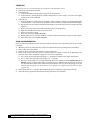
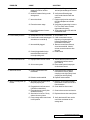
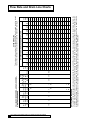
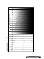
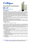
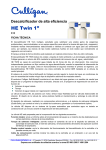
1
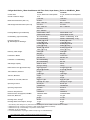
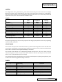
Cat. No. 01882344
Rev. A 3/8/01
DCO #2175
Service
Manual
CULLIGAN
SILVER SERIES™
AND GOLD SERIES™
AUTOMATIC
WATER CONDITIONER
MODELS FROM 2000
©2001 Culligan International Company
Printed in USA
Attention Culligan Customer:
The installation, service and maintenance of this equipment should
be rendered by a qualified and trained service technician. Your local
independently operated Culligan dealer employs trained service and
maintenance personnel who are experienced in the installation,
function and repair of Culligan equipment. This publication is written
specifically for these individuals and is intended for their use.
We encourage Culligan users to learn about Culligan products, but
we believe that product knowledge is best obtained by consulting
with your Culligan dealer. Untrained individuals who use this manual
assume the risk of any resulting property damage or personal injury.
WARNING - Prior to servicing equipment, disconnect power
supply to prevent electrical shock.
WARNING - If incorrectly installed, operated or maintained,
this product can cause severe injury. Those who install,
operate, or maintain this product should be trained in its proper
use, warned of its dangers, and should read the entire manual
before attempting to install, operate or maintain this product.
IF THIS EQUIPMENT IS TO BE USED IN THE TREATMENT
O F D R I N K I N G W AT E R , T H E W AT E R M U S T B E
M I C R O B I O L O G I C A L LY S A F E .
Service
Manual
CULLIGAN
SILVER SERIES™
AND GOLD SERIES™
AUTOMATIC
WATER CONDITIONER
MODELS FROM 2000
Table of Contents
Page
Introduction ............................................................... 2
Specifications ........................................................... 3
Familiarization ........................................................... 5
Programming ............................................................ 14
Manual Cycling ........................................................ 16
Service Check .......................................................... 17
Parts Replacement Guide ........................................ 18
Board Diagnostics .................................................... 22
Household Aqua-Sensor Sensing Device
Troubleshooting Guide .............................................. 23
Aqua-Sensor Troubleshooting Flowchart ................... 25
Troubleshooting Guide .............................................. 26
Wiring Diagram ........................................................ 29
"A" Dimension Charts/Refill Rates ............................ 30
Flow Rate and Drain Line Charts .............................. 32
Flow Charts .............................................................. 34
Introduction
The Culligan Silver Series™ and Gold Series™ water softeners are tested and validated by
WQA against ANSI/NSF Standard 44 for the effective reduction of calcium and magnesium,
along with Barium and Radium 226/228*.
SAFE PRACTICES
Throughout this manual there are paragraphs set off by special headings.
NOTICE: Notice is used to emphasize installation, operation or maintenance information which is important, but
does not present any hazard.
Example: NOTICE: The nipple must extend no more than 1 inch above the cover plate.
CAUTION: Caution is used when failure to follow directions could result in damage to equipment or
property. Example:
CAUTION: Disassembly while under water pressure can result in flooding.
WARNING: Warning is used to indicate a hazard which could cause injury or death if ignored. Example:
WARNING! ELECTRICAL SHOCK HAZARD! UNPLUG THE UNIT BEFORE
REMOVING THE COVER OR ACCESSING ANY INTERNAL CONTROL PARTS.
SERIAL NUMBERS
The control valve serial number is located on the back of the timer case.
The media tank serial number is located on the top surface of the tank.
NOTICE: Do not remove or destroy the serial number. It must be referenced on request for warranty repair or
replacement.
This publication is based on information available when approved for printing. Continuing design refinement
could cause changes that may not be included in this publication.
* Verified using hardness surrogate per ANSI/NSF Standard 44.
2
CULLIGAN SILVER SERIES AND GOLD SERIES WATER SOFTENERS
Specifications
Culligan Silver Series™ Water Conditioners with Time Clock, Aqua-Sensor® Device or Soft-Minder® Meter
Control Valve
Overall Conditioner Height
Media Tank Dimensions (Dia x Ht)
Salt Storage Tank Dimensions (Dia x Ht)
Exchange Media, Type and Quantity
Underbedding, Type and Quantity
Exchange Capacity
@ Salt Dosage Per Recharge1
Efficiency rated dosage1
Freeboard to Media2
Freeboard to Underbedding3
Salt Storage Capacity
Rated Service Flow @ Pressure Drop
Total Hardness, Maximum
Total Iron, Maximum
Hardness to Iron Ratio, Minimum
Operating Pressure
Operating Temperature
Electrical Requirements
Electrical Power Consumption, Min/Max
Drain Flow, Maximum4
Recharge Time, Average5
Recharge Water Consumption, Average
1
2
3
4
5
9” Model
5-cycle, Reinforced Thermoplastic
51 in
1 295 mm
9 x 45 in
229 x 1 143 mm
16 x 43 in
406 x 1 092 mm
18 x 43 in
457 x 1092 mm
Cullex® Media, 0.86 ft3
Cullex® Media, 24.5 L
Cullsan® Underbedding, 12 lb
Cullsan® Underbedding, 5.4 kg
17,500 gr @ 4.0 lb
1 133 g @ 1.8 kg
23,900 gr @ 8.0 lb
1 547 g @ 3.6 kg
26,600 gr @ 12.0 lb
1 722 g @ 5.4 kg
4 380 gr/lb
655 g/kg
16.6-17.6 in
420-447 mm
39.2 in
996 mm
250 lb or 375 lb
114 kg or 170 kg
7.5 gpm @ 15 psi
30 Lpm @ 102 kPa
75 gpg
1 283 mg/L
5 ppm
5 mg/L
8 gpg to 1 ppm
140 mg/L to 1 mg/L
20-125 psi
140-860 kPa
33-120°F
1-50°C
120V/60 Hz
3 Watts/35 Watts
2.0 gpm
8 Lpm
80 min
40 gal
170 L
12” Model
5-cycle, Reinforced Thermoplastic
51 in
1 295 mm
12 x 45 in
305 x 1 143 mm
18 x 43 in
457 x 1 092 mm
Cullex® Media, 1.4 ft3
Cullex® Media, 40 L
Cullsan® Underbedding, 30 lb
Cullsan® Underbedding, 14 kg
24,100 gr @ 6.0 lb
1 560 g @ 2.7 kg
34,500 gr @ 12.0 lb
2 234 g @ 5.4 kg
41,900 gr @ 18.0 lb
2 713 g @ 8.1 kg
4 010 gr/lb
640 g/kg
17.5-18.5 in
444-470 mm
38.5 in
978 mm
375 lb
170 kg
8.1 gpm @ 15 psi
31 Lpm @ 102 kPa
99 gpg
1 692 mg/L
5 ppm
5 mg/L
8 gpg to 1 ppm
140 mg/L to 1 mg/L
20-125 psi
140-860 kPa
33-120°F
1-50°C
120V/60 Hz
3 Watts/35 Watts
3.5 gpm
14 Lpm
85 min
82 gal
325 L
The efficiency rated dosage is only valid at the 4 lb. salt dosage for the 9" models and 6 lb. for the 12" models.
Measured from top of media to top surface of tank threads (backwashed and drained).
Measured from top of underbedding to top surface of tank threads.
Backwash at 120 psi (830 kPa).
10 minute backwash, 4 lb (1.8 kg) 9” model or 6 lb (2.7 kg) 12” model salt dosage.
SPECIFICATIONS
3
Culligan Gold Series™ Water Conditioners with Time Clock, Aqua-Sensor® Device or Soft-Minder® Meter
Control Valve
Overall Conditioner Height
Media Tank Dimensions (Dia x Ht)
Salt Storage Tank Dimensions (Dia x Ht)
Exchange Media, Type and Quantity
Underbedding, Type and Quantity
Exchange Capacity
@ Salt Dosage Per Recharge1
Efficiency rated dosage1
Freeboard to Media2
Freeboard to Underbedding3
Salt Storage Capacity
Rated Service Flow @ Pressure Drop
Total Hardness, Maximum
Total Iron, Maximum
Hardness to Iron Ratio, Minimum
Operating Pressure
Operating Temperature
Electrical Requirements
Electrical Power Consumption, Min/Max
Drain Flow, Maximum4
Recharge Time, Average5
Recharge Water Consumption, Average
1
2
3
4
5
9” Model
5-cycle, Reinforced Thermoplastic
52 in
1 320 mm
9 x 45 in
229 x 1 143 mm
16 x 43 in
406 x 1 092 mm
18 x 43 in
457 x 1092 mm
Cullex® Media, 1.00 ft3
Cullex® Media, 28.32 L
No Underbedding
No Underbedding
18,200 gr @ 4.0 lb
1 179 g @ 1.8 kg
27,300 gr @ 8.0 lb
1 769 g @ 3.6 kg
30,900 gr @ 12.0 lb
2 002 g @ 5.4 kg
4 550 gr/lb
655 g/kg
13.5-15.5 in
343-394 mm
No Underbedding
No Underbedding
250 lb or 375 lb
114 kg or 170 kg
9 gpm @ 15 psi
30 Lpm @ 102 kPa
75 gpg
1 283 mg/L
5 ppm
5 mg/L
8 gpg to 1 ppm
140 mg/L to 1 mg/L
20-125 psi
140-860 kPa
33-120°F
1-50°C
120V/60 Hz
3 Watts/35 Watts
2.0 gpm
8 Lpm
68 min
43 gal
162 L
12” Model
5-cycle, Reinforced Thermoplastic
52 in
1 320 mm
12 x 45 in
305 x 1 143 mm
18 x 43 in
457 x 1 092 mm
Cullex® Media, 1.5 ft3
Cullex® Media, 42.48 L
Cullsan® Underbedding, 30 lb
Cullsan® Underbedding, 14 kg
26,900 gr @ 6.0 lb
1 743 g @ 2.7 kg
39,600 gr @ 12.0 lb
2 566 g @ 5.4 kg
45,400 gr @ 18.0 lb
2 942 g @ 8.1 kg
4 483 gr/lb
640 g/kg
13.0-15.0 in
330-381 mm
37.0 in
940 mm
375 lb
170 kg
10.5 gpm @ 15 psi
31 Lpm @ 102 kPa
99 gpg
1 692 mg/L
5 ppm
5 mg/L
8 gpg to 1 ppm
140 mg/L to 1 mg/L
20-125 psi
140-860 kPa
33-120°F
1-50°C
120V/60 Hz
3 Watts/35 Watts
3.5 gpm
14 Lpm
57 min
83 gal
314 L
The efficiency rated dosage is only valid at the 4 lb. salt dosage for the 9" models and 6 lb. for the 12" models.
Measured from top of media to top surface of tank threads (backwashed and drained).
Measured from top of underbedding to top surface of tank threads.
Backwash at 120 psi (830 kPa).
10 minute backwash, 4 lb (1.8 kg) 9” model or 6 lb (2.7 kg) 12” model salt dosage.
4
CULLIGAN SILVER SERIES™ AND GOLD SERIES WATER SOFTENERS
Familiarization
CONTROL
The Culligan Silver Series™ and Gold Series™ water softener uses the same power valve control as in our Culligan
Mark 89/812 models. It can be programmed as either a time clock, Aqua-Sensor® sensing device or Soft-Minder®
meter model. Each model has its own programming parameters which can be set to control the operation and
regeneration of the system. These functions are outlined in Table 1.
TABLE 1
Function
1. Time of Day
2. Time of Regen.
3. Not Used
4. Salt Dosage
5. Backwash Time
6. Brine Rinse Time
7. Hardness Level
8. Gallons Capacity / Regen. Interval
8A. Forced Regeneration Interval
9. Lock/Unlock display
10. Blanking Feature
Time
Clock
YES
YES
NO
YES
YES
YES
NO
YES
NO
YES
YES
Soft-Minder
Meter
YES
YES
NO
YES
YES
YES
YES
YES
YES*
YES
YES
Aqua-Sensor
Sensing
Device
YES
YES
NO
YES
YES
YES
NO
NO
YES*
YES
YES
* When dip switch #10 is in the ON position
During the programming stage, the user will be prompted to enter the appropriate parameter. Refer to the programming
section for further information.
CIRCUIT BOARD
The AccuSoft™ microprocessor circuit board controls every function of the Culligan Silver Series and Gold Series
water softeners. This board has several unique features which allow it to perform a variety of functions. Familiarization
of the board is essential for a thorough understanding of the softener.
The AccuSoft circuit board has a set of default settings that the microprocessor will reset to whenever any dip
switches are flipped, or if a meter or Aqua-Sensor cable is attached or removed while the power is on the control.
Table 2 is a list of the default microprocessor settings.
It is recommended to always disconnect the power from the circuit board prior to replacing an Aqua-Sensor probe
or Meter cable so that the programmed settings are not lost.
TABLE 2
1
2
3
4
5
6
7
8
9
10
Time of Day
Time of Regeneration
Chlorination (Not Used)
Salt Dosage
Backwash Time
Brine Rinse
Hardness
Regeneration Interval
Display Blanking
Display Lock Out
12:00 A.M.
2:00 A.M.
10 min.
10 lb. for 9"; 16 lb. for 12"
10 min.
71 min. for 9"; 59 min. for 12"
20 GPG
3 days
Enabled
Disabled
FAMILIARIZATION
5
PROGRAMMING SWITCHES
The circuit board will require the proper setting of the dip switches in order to function properly. Figure 1 shows the
dip switches.
Switch 1 - Sets the unit in the Run or Test mode.
Switch 2 - Sets the unit for Filter or Softener.
Switch 3 - Sets the flow meter K factor for the 3/4" or 1-1/4" flow meter.
Switch 4 - Sets the control for 9” or 12” diameter tanks.
Switch 5 - Sets the unit for the standard or accelerated Refill cycle.
NOTICE: For an accelerated Refill cycle, the refill flow control in the brine refill assembly must be changed to PN
00-4016-23.
Switch 6 - Sets the unit for immediate or delayed regeneration.
Switch 7 - Sets the unit to measure in liters and French or German hardness, or in gallons and the conventional gpg
hardness.
Switch 8 - Sets the unit to display time with a 24 or 12 hour clock.
Switch 9 - Sets the unit for either French or German hardness degrees when switch #7 is in the ON position.
Switch 10 - When turned ON, the microprocessor will force a regeneration based on the setting 8A in the menu.
Dip Switch
Function
Default (OFF) Position
1
Run or Test Mode
Run Mode
2
Filter or Softener
Softener
3
Flow Meter K Factor (3/4" or 1-1/4")
3/4" Flow Meter
4
9" - 12" Tank Settings
9" Tank
5
Standard vs. Accelerated Refill
Standard Refill
6
Delay vs. Immediate Regeneration
Delayed Regeneration
7
English vs. Metric Settings
English Settings
8
12 or 24 Hour Clock
12 Hour Clock
9
German or French Hardness Degrees German (When #7 is ON)
10
Time Clock Backup
No Forced Regeneration
FIG. 1
AUXILIARY CONNECTIONS
Refer to Figure 2 for all circuit board connections. Power
terminals are located along the lower section of the
circuit board. The connection marked 'POWER' is for
the transformer connector, and the motor connection is
marked 'MOTOR'. The connection for the cam switch
harness, marked 'CAM', is located in the upper right
corner near the dip switches. The Aqua-Sensor sensing
device connection is located in the lower center of the
board, just above the power connectors, while the SoftMinder connection is located in the upper left side of
the board. Just below the meter connection is a
connection marked 'BATT', which is for the optional
battery back-up. All terminals are clearly marked to ease
installation.
FIG. 2
6
CULLIGAN SILVER SERIES™ AND GOLD SERIES™ WATER SOFTENERS
AQUA-SENSOR® OPERATION
The Aqua-Sensor Sensing Device utilizes a pair of cells to sense the passage of hardness through the water
softener. It can automatically adjust for water with variable hardness levels. As a result, it is the most efficient means
of operating a water softener. When hardness is sensed, the unit signals for a regeneration. The "REGEN" enunciator
will light at this point. The unit will perform a standard regeneration cycle at the preset time, unless the number 6 dip
switch is turned on. When the number 6 dip switch is in the "ON" position, a regeneration will begin immediately.
The Aqua-Sensor models contain a feature which can automatically detect when the brine solution has been rinsed
through the Cullex® media. This feature will advance the control to the next position when it senses that the brine
has been rinsed out prior to the time set in the Brine/Rinse option.
Tables 3A and 3B show the total capacity of the Aqua-Sensor at various salt dosages, along with the average
capacity used prior to a signal calling for regeneration.
Since the Aqua-Sensor device automatically senses hardness in the water, the programming is limited to the Timeof-Day, Time-of-Regeneration, Salt Dosage, Backwash Time and Brine/Rinse settings. The numeric enunciator will
only light for those programming options (numbers 1-6, 9, and 10). Refer to the programming section for further
information on programming the microprocessor.
SOFT-MINDER® OPERATION
The Soft-Minder meter utilizes a turbine impeller to accurately monitor the customers water usage. After a
predetermined amount of water has passed through the system, the microprocessor will signal a regeneration. The
"REGEN" enunciator will light at this point. The unit will perform a standard regeneration cycle at the preset time,
unless the number 6 dip switch is turned on. When the number 6 dip switch is in the "ON" position, a regeneration
will begin immediately.
The microprocessor automatically calculates the gallons of water which can be treated based on the salt dosage, the
water hardness, and the tank size. Refer to Tables 4B and 5B for capacity and reserve values that the microprocessor
will use based on its settings. The GALLONS TO SIGNAL setting can be manually set to directly override the
microprocessor calculations. This setting can be modified when positioned at numeric enunciator 8. The gallon
value may need to be raised or lowered to meet the needs of your specific application. The control must be cycled
through a complete regeneration before the gallon override setting is stored by the microprocessor.
NOTICE: Changing the capacity will affect the reserve capacity. An INCREASE in the gallons capacity will
DECREASE the reserve capacity. A DECREASE in the gallons capacity will INCREASE the reserve capacity.
Refer to Tables 4B and 5B to determine the units total capacity based on salt dosage and the hardness level.
The programming of the Soft-Minder provides several settable variables, the Time-of-Day, Time-of-Regeneration,
Salt Dosage, Backwash Time, Brine/Rinse Time, Hardness, and Gallons to Signal. The numeric enunciator will light
for programming sequences 1-10. Refer to the programming section for further information on programming the
microprocessor.
NOTICE: Dip switch #3 needs to be in the "ON" position for the meter to correctly count gallons.
TIME CLOCK OPERATION
When the microprocessor is set-up as a time clock unit, the Culligan Silver Series™ and Gold Series™ control will
regenerate at fixed intervals which are determined by the water hardness, the salt dosage, and the household's water
usage. To calculate the regeneration interval, locate the total gallon capacity in Table 4B and 5B based on the salt
dosage and the water hardness. Divide the units total capacity by the anticipated daily gallon usage for the
household. This value is the regeneration interval, always round this value up to the nearest whole number. This
regeneration interval can be set anywhere from 1 to 42 days.
The programming for the time clock models is limited to Time-of-Day, Time-of-Regeneration, Salt Dosage, Backwash
Time, Brine/Rinse Time, and the Regeneration Interval. The numeric enunciator will only light for those programming
options (number 1-6, and 8-10). Refer to the programming section for further information on programming the
microprocessor.
FAMILIARIZATION
7
CAPACITY AND SALT SETTINGS
The current software calculates the gallon capacities based on the yoke style tanks. The yoke style tanks have 0.86
ft3 of Cullex® resin in the 9" tanks and 1.4 ft3 of Cullex resin in the 12" tanks, whereas the new center opening tanks
have 1.0 ft3 in the 9" tanks and 1.5 ft3 of Cullex resin in the 12" tanks. To take advantage of the additional capacities
obtained with the added resin follow the procedure listed below for calculating the capacity settings.
1. Compensated Water Hardness.
If your water supply contains iron, compensate for it by the following procedure:
1. Multiply the iron by 0.1 and add the result to the hardness.
Example: (3 ppm of iron x 0.1) + 25 gpg of hardness = 25.3 gpg of total hardness
2. Choose the % capacity you want and refer to the table below for the appropriate multiplier.
Example: 67% capacity gives a multiplier of 1.5.
TABLE 3
% Capacity
Multiplier
50%
67%
75%
2
1.5
1.33
3. Multiply the result from Step 1 by the multiplier chosen in Step 2. This is the compensated hardness.
Example: 25.3 gpg total hardness x 1.5 = 38 gpg compensated hardess.
4. Use the effective hardness for sizing and to determine salt dosage and regeneration frequency.
5. The forced regeneration feature should be used for Soft-Minder meter operation to ensure the resin bed
does not become iron fouled due to lack of water flow. See "Programming the Option Settings" for the
forced regeneration feature.
2. Salt Dosage
From Table 4, select the salt dosage at which the softener will be operated.
• Low Setting — Maximum salt efficiency, more frequent regeneration, reduced overall softening capacity.
• Medium Setting — Good combination of efficiency and overall softening capacity.
• High Setting — Maximum softening capacity, less frequent regeneration, and reduced salt efficiency.
Recommended whenever iron is present and for hardness levels above 30 Grains Per Gallon, or high volume
water usage.
TABLE 4 - SALT DOSAGE
Capacity
Salt
Capacity
Dosage 9" Tank
12" Tank
4
18,200
X
5
21,500
27,000
6
23,500
29,600
7
25,000
31,400
8
27,300
33,100
9
27,800
34,700
10
28,900
36,300
11
30,000
37,500
12
30,900
39,600
13
31,900
40,000
14
32,700
41,000
15
33,500
42,000
16
X
42,900
17
X
43,700
18
X
45,400
19
X
45,500
20
X
46,100
8
160 lb. Brine Tank
"A" Dimension
Secondary (Only)
in.
(cm)
7-3/4
19.7
9-1/2
24.1
11-1/4
28.6
13
33
14-3/4
37.5
16-1/2
42
18-1/4
46.3
20
51
21-3/4
55.2
21-1/2
59.7
25-1/4
64.1
—
—
—
—
—
—
—
—
—
—
—
—
250 lb. Brine Tank
"A" Dimension
Secondary Primary
in.
(cm)
in.
(cm)
6-5/8 16.8 4-5/8 11.7
8
20.3
6
15.2
9-3/8 23.8 7-3/8 18.7
10-7/8 27.6 8-7/8 22.5
12-1/4 31.1 10-1/4 26
13-5/8 34.6 11-5/8 29.5
15
38.1
13
33
16-3/8 41.6 14-3/8 36.5
17-3/4 45.1 15-3/4 40
19-1/8 48.6 17-1/8 43.5
20-1/2 52.1 18-1/2 47
21-7/8 55.5 19-7/8 50.5
23-1/4 59 21-1/4 54
24-5/8 62.5 22-5/8 57.5
26
66
24
61
27-3/8 69.5 25-3/8 64.5
28-3/4 73 26-3/4 68
CULLIGAN SILVER SERIES AND GOLD SERIES WATER SOFTENERS
375 lb. Brine Tank
"A" Dimension
Secondary Primary
in.
(cm)
in.
(cm)
5-1/2 14.0 3-1/2
8.9
6-1/2 16.5 4-1/2 11.4
7-1/2
19
5-1/2
14
8-1/2 21.6 6-1/2 16.5
9-1/2 24.1 7-1/2
19
10-1/2 26.7 8-1/2 21.6
11-1/2 29.2 9-1/2 24.1
12-1/2 31.7 10-1/2 26.7
13-1/2 34.3 11-1/2 29.2
14-1/2 36.8 12-1/2 31.7
15-1/2 39.4 13-1/2 34.3
16-1/2 42 14-1/2 36.8
17-1/2 44.5 15-1/2 39.4
18-1/2 47 16-1/2 42
19-1/2 49.5 17-1/2 44.5
20-1/2 52.1 18-1/2 47
21-1/2 54.6 19-1/2 49.5
3. Treated Water Volume Set Point
Calculate the treated water volume set point using the following information:
• Softening capacity — Grains (based upon salt dosage setting).
• Compensated hardness of water supply — Grains Per Gallon
• Estimated daily water usage — Gallons Per Day (refer to Table 5)
TABLE 5 - Daily Water Usage
Persons in Household
2
3
4
5
6
7
8
9
10
Gallons Per Day
150
225
300
375
450
525
600
675
750
Example - Soft-Minder® Meter Models
Capacity @ 8 lb. Salt Dosage: 27,300 Grains
Compensated Water Hardness: 19 Grains Per Gallon
Estimated Daily Water Usage: 300 Gallons Per Day
Treated Water Volume Set Point =
Softener Capacity
— Water Usage
Compensated Hardness
Softening Capacity
Divide by Compensated Hardness
Result is total number of gallons
of soft water per regeneration
Subtract daily Water Usage (needed
as a reserve to ensure continuous
soft water until regeneration occurs).
Round down to nearest ten for Treated
Water Volume Set Point
Set numeric enunciator number 8 to 113
27,300 Grains
÷ 19 Grains per Gallon
1,437 Gallons
— 300 Daily Water Usage (One Day Supply)
1,137 Gallons
1,137 Gallon Setting
Example - Timeclock Model
Capacity @ 8 lb. Salt Dosage: 27,300 Grains
Compensated Water Hardness: 19 Grains Per Gallon
Estimated Daily Water Usage: 300 Gallons Per Day
Softener Capacity
Treated Water Volume Set Point = Compensated Hardness — Water Usage
Softening Capacity
Divide by Compensated Hardness
Result is total number of gallons
of soft water per regeneration
Subtract daily Water Usage (needed
as a reserve to ensure continuous
soft water until regeneration occurs).
Divide by daily water usage
Round down to nearest day
Set numeric enunciator number 8 to 3
27,300 Grains
÷ 19 Grains per Gallon
1,437 Gallons
— 300 Daily Water Usage (One Day Supply)
1,137 Gallons
÷ 300
3.8 Days
3.0 Days
FAMILIARIZATION
9
Use the following worksheets to calculate and record the proper settings.
Treated Water Volume Set Point Work Sheet - Meter Models
1. Enter Softening Capacity
2. Divide by Compensation Hardness
Result is Total Gallons of Soft Water Per Regeneration
3. Subtract Daily Water Usage (Reserve
Result
÷
=
—
=
Round down to nearest ten for Treated Water Volume Set Point
Gallons
Treated Water Volume Set Point Work Sheet - Timeclock Models
1. Enter Softening Capacity
2. Divide by Compensation Hardness
Result is Total Gallons of Soft Water Per Regeneration
÷
=
3. Subtract Daily Water Usage (Reserve
—
4. Divide by Daily Water Usage
÷
Result
Round down to nearest ten for days between regeneration set point
=
Days
Note: All Softening capacity is based on using sodium chloride as the regenerate: If potassium chloride is used
reduce the rated softening capacity by 20%. All capacities are based on new Cullex®.
REGENERATION
There are several conditions that will cause the control to trip a regeneration. The 'REGEN' enunciator will light
when the control has signaled for a regeneration. The 'REGEN' enunciator will flash while the control is in regeneration.
The following are conditions that will call for regeneration:
1.
2.
3.
4.
5.
6.
7.
When the Aqua-Sensor® probe senses the hardness in the Cullex® media.
When the Soft-Minder® meter has recorded the passage of a predetermined number of gallons.
When the time clock has counted past the set number of days.
At the preset time, when the number of days without a regeneration is equal to the days set in menu #8A.
At the preset time, when the 'REGEN.’ button is depressed once. 'REGEN.' will light.
Immediately, when the ‘REGEN.” button is depressed twice. 'REGEN.' will light and blink.
Immediately, if power to the unit has been off for more than 3 hours.
If dip switch 6 is in the ON position the unit will begin a regeneration immediately for instances 1 and 2. With dip
switch 6 in the OFF position, the regeneration will not begin until the preset regeneration time.
DISPLAY BLANKING
As shipped from the factory, the display of the board will turn off if there has been no keypad activity for a 1 minute
period. To have the display constantly lit, press the STATUS button until the number 10 icon is lit. Next, press the
UP arrow. A “d” for disable will appear in the display. To have the display blank again , press the UP arrow. An “E”
will appear in the display .
10 CULLIGAN SILVER SERIES AND GOLD SERIES WATER SOFTENERS
DISPLAY LOCKOUT
The Culligan Silver Series™ and Gold Series™ control is equipped with a feature which will allow you to protect the
programmed settings from tampering by unauthorized individuals. When the lockout feature is activated, the only
parameter which can be adjusted is the Time-of-Day.
To activate the lockout feature, press the STATUS button until the number 9 icon is illuminated. A “U” for unlock will
be displayed. Press the UP and DOWN arrows simultaneously. A “L” for lock will appear along with an icon of a lock.
All program parameters, except time of day, are now frozen at their current settings. To disable this feature, press the
UP and DOWN arrows simultaneously.
POWER LOSS
The AccuSoft® circuit board is equipped with a Hi-Cap Capacitor and EEPROM memory chip. The capacitor is
capable of maintaining the time, for at least one day, in the event of a power outage. The EEPROM ensures that the
individual programming parameters of the softener are not lost.
If the power outage lasts long enough to drain the Hi-Cap Capacitor, the control will flash "12:00 PM" when power
is returned to the control. The unit will continue to keep time from the moment power is restored, and will initiate a
full regeneration at the preset regeneration time. The time of day will need to be reset in order to return the
regeneration to its preset time.
FAILURE MODE
The Culligan Silver Series and Gold Series control is equipped to detect a motor or piston which is locked in a frozen
position. The AccuSoft™ circuit board will apply power to the motor for 30 seconds. If there is no change in the
motor homing or position switch, the control will power down for 90 seconds. The circuit board will repeat this
procedure two more times in an attempt to remove the obstruction. If no movement has been detected, the control
will permanently power down and a phone icon will appear in the display. The phone indicates that a service call is
required to fix the control. To return to the service mode, turn off the power to the unit for 1 full minute and remove
the obstruction to the motor or piston.
FAMILIARIZATION 11
12 CULLIGAN SILVER SERIES™ AND GOLD SERIES™ WATER SOFTENERS
(37.5)
15-3/4
(40.0)
21-3/4
(55.2)
375 LB
(26.9)
11-3/8
(19.1)
7-1/2
IN (CM)
TOTAL CAPACITY
CAPACITY TO SIGNAL
TOTAL CAPACITY
CAPACITY TO SIGNAL
(11.7)
(19.7)
12
8
4-5/8
7-3/4
4
(40.0)
(55.2)
(23.5)
15-3/4
(37.5)
21-3/4
9-1/4
14-3/4
IN (CM)
IN (CM)
DOSAGE
250 LB
160 LB
SALT
"A" DIMENSION
(26.9)
11-3/8
(19.1)
7-1/2
(8.9)
3-1/4
IN (CM)
375 LB
CAPACITY TO SIGNAL
TOTAL CAPACITY
CAPACITY TO SIGNAL
TOTAL CAPACITY
CAPACITY TO SIGNAL
TOTAL CAPACITY
TABLE 6B - CAPACITY, 9" SOFT-MINDER® METER (GALLONS)
12
9-1/4
(23.5)
14-3/4
8
250 LB
IN (CM)
160 LB
IN (CM)
SALT
DOSAGE
"A" DIMENSION
6-10
707
980
849
637
805
731
813
631
980
495
644
3,656 1,828 1,195
896
696
5,420 2,710 1,807 1,355 1,084
3,314 1,657 1,084
4,900 2,450 1,633 1,225
2,596 1,298
914
609
903
590
817
457
678
442
613
406
602
393
544
HARDNESS
522
774
505
700
366
542
354
490
332
493
322
445
305
452
281
417
261
387
244
301
580
903
526
817
412
537
487
774
442
700
426
678
387
613
367
602
333
544
331
542
300
490
294
493
267
445
270
452
246
417
229
387
209
361
11-15 16-20 21-25 26-30 31-35 36-40 41-45 46-50 51-55 56-60 61-65 66-70 71-75
3,220 1,610 1,073
6-10
3,656 1,828 1,219
5,420 2,710 1,807 1,355 1,084
3,537 1,949 1,179 1,004
1-5
HARDNESS
11-15 16-20 21-25 26-30 31-35 36-40 41-45 46-50 51-55 56-60 61-65 66-70 71-75
4,900 2,450 1,633 1,225
1-5
TABLE 6A - CAPACITY, 9" AQUA-SENSOR® SENSING DEVICE (GALLONS)
FAMILIARIZATION 13
375 LB
17-1/4
(43.8)
24-1/2
(62.2)
(28.9)
11-3/8
IN (CM)
TOTAL CAPACITY
CAPACITY TO SIGNAL
TOTAL CAPACITY
CAPACITY TO SIGNAL
(18.7)
(37.5)
18
12
7-3/8
14-3/4
6
(43.8)
(62.2)
(28.9)
17-1/4
(40.0)
11-3/8
(14.0)
5-1/2
IN (CM)
375 LB
24-1/2
(56.2)
N/A
15-3/4
21-3/4
IN (CM)
IN (CM)
DOSAGE
250 LB
"A" DIMENSION
160 LB
SALT
CAPACITY TO SIGNAL
TOTAL CAPACITY
CAPACITY TO SIGNAL
TOTAL CAPACITY
CAPACITY TO SIGNAL
TOTAL CAPACITY
1-5
6-10
HARDNESS
908
757
649
6-10
867
650
958
578
851
505
749
HARDNESS
743
568
843
520
766
454
674
433
638
379
562
371
547
479
325
426
289
383
260
857
666
555
753
920
767
644
963
466
646
5,346 2,673 1,748 1,311 1,018
849
713
7,660 3,830 2,553 1,915 1,532 1,277 1,094
4,832 2,416 1,580 1,185
6,740 3,370 2,247 1,685 1,348 1,123
3,495 1,748 1,143
904
624
958
564
843
408
565
537
851
486
749
484
766
437
674
395
638
357
562
335
547
286
479
246
426
219
383
11-15 16-20 21-25 26-30 31-35 36-40 41-45 46-50 51-55 56-60 61-65 66-70 71-75
4,520 2,260 1,507 1,130
1-5
5,200 2,600 1,733 1,300 1,040
7,660 3,830 2,553 1,915 1,532 1,277 1,094
4,542 2,271 1,514 1,136
963
11-15 16-20 21-25 26-30 31-35 36-40 41-45 46-50 51-55 56-60 61-65 66-70 71-75
6,740 3,370 2,247 1,685 1,348 1,123
TABLE 7B - CAPACITY, 12" SOFT-MINDER® METER (GALLONS)
N/A
(40.0)
(56.2)
18
15-3/4
21-3/4
12
250 LB
IN (CM)
160 LB
IN (CM)
SALT
DOSAGE
"A" DIMENSION
TABLE 7A - CAPACITY, 12" TIMECLOCK AND AQUA-SENSOR® SENSING DEVICE (GALLONS)
Programming
The display will initially power up flashing "12:00 PM". After 1 minute the motor will energize and cycle the control,
without stopping, to the home position. This is required to ensure that the control is in the home position.
FIG. 3 - Circuit Board Display
The timer uses four buttons:
1.
2.
3.
4.
STATUS:
UP ARROW:
DOWN ARROW:
REGEN.:
Advance timer through display options.
Increase the setting.
Decrease the setting.
Initiate a manual regeneration.
SETTING THE MICROPROCESSOR
The microprocessor senses when it is installed as a Soft-Minder or Aqua-Sensor® control. Adding or removing any
connection to the board, or flipping any of the dip switches will automatically reset the microprocessor to the
factory settings.
1.
2.
3.
4.
5.
With a flashing or blank display, pressing the status button twice will
move to the Time-of-Day adjustment, adjust the time by using the up
and down arrows. A number “1” will appear at the bottom of the
display while in this mode.
Press
▲ to increase or
▼ to decrease
Press
▲ to increase or
▼ to decrease
Press
▲ to increase or
▼ to decrease
Press
▲ to increase or
▼ to decrease
Press
▲ to increase or
▼ to decrease
Press status again, this displays the Time-of-Regeneration for delayed
units, adjust using the up and down arrows. A number “2” will appear
at the bottom of the display while in this mode.
Press status again, the number “3” will appear at the bottom of the
display. This setting is not used, and any changes made will not
affect the operation of the microprocessor.
Pressing status again will show the Salt Dosage. This can be adjusted
with the up and down arrows, the range is 3-15 lbs. for the 9” controls
and 5-24 lbs. on 12” controls. A number “4” will appear at the bottom
of the display while in this mode.
Press status again, this displays the Backwash Time in minutes. The
setting can be adjusted between 5 and 40 minutes by using the up
and down arrows. A number “5” will appear at the bottom of the
display while in this mode.
14 CULLIGAN SILVER SERIES™ AND GOLD SERIES™ WATER SOFTENERS
6.
7.
8.
Press status again to display the Brine/Rinse Time in minutes. The
settings can be adjusted using the up and down arrows (37-85 min for
9”, 35-89 min for 12”). A number “6” will appear at the bottom of the
display while in this mode.
Press
▲ to increase or
▼ to decrease
Press status again to display the Hardness Level in grains per gallon.
The setting can be adjusted from 2-99 gpg by using the up and down
arrows. This screen will not appear when the Aqua-Sensor® probe is
attached. A number “7” will appear at the bottom of the display while
in this mode.
Press
▲ to increase or
▼ to decrease
Press status again, for time clock models the display will show the
Regeneration Interval. The setting can be adjusted using the up and
down arrows. Controls with a Soft-Minder® meter will display the
Gallons to Signal (multiply the displayed value by 10). A number “8”
will appear at the bottom of the display while in this mode.
Press
▲ to increase or
▼ to decrease
Press
▲ to increase or
▼ to decrease
Press
▲ simultaneously
▼
Press
▲ to change
8A. Display menu '8A' will light when dip switch #10 is in the ON position.
This is the Time Clock Backup feature. The control will force a
regeneration, within a range of 1-42 days, when in the Aqua-Sensor®
or Soft-Minder® meter mode.
9.
Pressing status again will display the Lock/Unlock feature. A “U” in
the display signifies an unlocked microprocessor, while a “L” will lock
the settings except for the time of day. To toggle between the two
settings press both arrow keys simultaneously. A number “9” will
appear at the bottom of the display while in this mode.
10. Pressing status again brings up the ability to Enable/Disable the
screen blanking. To have the display constantly lit, press the up
arrow, a “d” for disable will appear in the display. Pressing the up
arrow again displays an “E”, signifying that display blanking is
enabled. A number “10” will appear at the bottom of the display while
in this mode.
NOTICE: Programming changes are not locked into the microprocessor memory until the control completes a
regeneration cycle. To initiate a manual regeneration, press the REGEN. button twice, the "REGEN" enunciator
will flash on the display. Refer to the Manual Cycling section on how to step through the regeneration stages.
PROGRAMMING 15
Manual Cycling
The Culligan® microprocessor can be indexed through the various regeneration stages. For all steps, the cycle
numbers do not appear, or change, until the motor stops.
1.
Press the status button to move past steps 1-10 until the display
is blank. Push the up arrow. The number “11” icon will light up.
An "H" will appear in the display. The control is in the HOME
position. Pressing the regen button once will light the 'REGEN'
icon.
2.
Press the regen button one more time. The 'REGEN' icon will
blink, and the motor will advance the control. A '1' will appear.
The unit is now in the BACKWASH position. The numbers to
the right indicate the time remaining for the cycle.
3.
Press the up arrow. A '2' will appear in the display, along with the
cycle time remaining. The control is in the BRINE DRAW/SLOW
RINSE cycle.
4.
Press the up arrow. A '3' will appear in the display, along with the
cycle time remaining. The control is in the FAST RINSE/BRINE
REFILL cycle.
5.
Press the up arrow. An 'H' will appear in the display. The unit is in
the HOME position. The 'REGEN' enunciator is no longer blinking.
An 'H 20' will appear on the Aqua-Sensor® models.
6.
Press the status key. Time-of-Day appears in the display.
16 CULLIGAN SILVER SERIES™ AND GOLD SERIES™ WATER SOFTENERS
Service Check
The service check mode allows one to view the instantaneous flow rate, the days since the last regeneration, the
total number of regenerations, the regenerations in the past fourteen days, and the gallons remaining.
To enter the service check mode, follow these steps:
1.
Press the status key to move past steps 1-10 until the display is
blank.
2.
Push the down arrow. The number '12' will appear only when the
Soft-Minder® meter is connected. The display reads the gallons
per minute flow rate. This screen will update with the current
meter reading every 6 seconds.
3.
Press the down arrow. The number '13' and an "A" will light at
the bottom of the display. The display will indicate the number of
regenerations that have occurred in the last 14 days.
4.
Press the down arrow. The number '13' and a 'B' will light at the
bottom of the display. The display will indicate the total number
of regenerations this control has cycled through.
5.
Press the down arrow. The number '14' will light at the bottom of
the display. The number in the display indicates the number of
days since last regeneration.
6.
Press the down arrow. The number '15' will be displayed if the
flow meter or Aqua-Sensor® is connected. For the controls with
the Soft-Minder® meter, the display indicates the gallons
remaining before the unit signals for regeneration (multiply the
displayed number by 10). For Aqua-Sensor® controls, the number
indicates the total minutes of the last brine rinse cycle.
NOTICE: Pushing the up arrow at any of these displays will immediately bring you to the control position
display, the number '11' will light at the bottom of the display.
SERVICE CHECK 17
Parts Replacement Guide
Familiarize yourself with the replacement procedures and component parts thoroughly before attempting any repair.
WARNING! DISCONNECT ALL ELECTRICAL POWER TO THE UNIT
BEFORE SERVICING. BYPASS THE UNIT AND RELIEVE SYSTEM
PRESSURE BEFORE ATTEMPTING REPAIR.
CIRCUIT BOARD
To replace the AccuSoft™ circuit board, refer to the parts list and proceed as follows:
1.
Remove the timer cover be removing the two screws located in the front of the cover.
2.
Swing the circuit board mounting plate out, and lift it off of the two hinge posts.
3.
Remove all connected wire leads from the board.
CAUTION: Grip all connections to the circuit board by the connecting
terminals for assembly and disassembly. Failure to do so could result in damage
to the wire leads or connecting terminals
4.
Remove the four screws holding the board to the mounting plate. See Figure 4.
CAUTION: Do not touch any surfaces of the circuit board. Electrical static
discharges may cause damage to the board. Handle the AccuSoft™ circuit board by
holding olny the edges of the circuit board. Keep replacement boards in their special
anti-static bags until ready for use. Mishandling of the circuit board will void
the warranty.
5.
The new circuit board can be installed by reversing the steps 1-4 above.
CAUTION: The wire connectors must be connected to the circuit board properly.
The wires must exit the plug-in connector opposite of the raised white base of the
circuit board connector.
FIG. 4
18 CULLIGAN SILVER SERIES™ AND GOLD SERIES™ WATER SOFTENERS
Refer to Figure 5 for assembly and disassembly of the various valve components listed below.
DRIVE MOTOR ASSEMBLY
1.
2.
3.
4.
5.
6.
7.
Remove the drive motor cam switches by removing the one screw holding the switches to the motor
Remove the E-ring holding the drive motor cam to the camshaft with a flat tip screwdriver.
Lift the cam off the shaft.
Using a 1/4" hex driver, remove the bolt above the eductor piston assembly.
Loosen the two screws holding the yoke support plate and the motor to the control valve.
Remove the yoke support plate and yoke by gently pulling them down.
Fully remove the two screws holding the motor to the control. The motor will pull away from the control and
the backplate will be hanging free.
NOTICE: If the unit is equipped with a meter, it is recommended to unclip the meter cable from the meter body to
allow backplate movement. The Aqua-Sensor probe will have to be disconnected from the circuit board and the
strain relief in the backplate will need to be removed.
NOTICE: Care should be taken to not damage the brine piston if it is not going to be replaced. The brine piston
will need to be twisted slightly in order to remove it from the motor die casting.
This procedure can be followed in the reverse order to reassemble the backplate and motor to the control. When
reassembling the scotch yoke, the yoke must slide into the yoke support plate prior to pushing the assembly up into
the piston end and follower. Figure 6 shows proper assembly of the yoke into the support plate.
NOTICE: The seal pack may need to be repositioned in order for the follower to be inserted into the yoke, using
the motor and backplate to push the seal pack fully into the valve is helpfull in aligning the yoke. Make sure that
the follower is in the follower slot on the yoke, and that the end of the piston rod is held in the end of the yoke.
NOTICE: When attaching the support plate be certain to push up on the plate until the two mounting screws
bottom in the U-shaped channels of the support plate.
FIG. 5
PARTS REPLACEMENT GUIDE 19
SEAL PACK ASSEMBLY
Follow the instructions for the replacing drive motor assembly through step 7, then continue as follows:
1.
2.
3.
With the drive motor and backplate set aside, firmly pull the seal pack assembly from the valve body.
Lightly lubricate the o-rings of the replacement seal pack with silicone grease.
Reverse the procedure for reassembly.
NOTICE: Use only silicone grease; petroleum-based lubricants will cause the degradation of the rubber components.
CAUTION: Do not twist the seal pack upon insertion. This can cause the outer
o-rings to pinch, cut, or crimp.
FIG. 6
EDUCTOR PISTON/EDUCTOR SLEEVE ASSEMBLY
Follow the instructions for the replacing drive motor assembly through step 7, then continue as follows:
1.
2.
3.
With the drive motor and backplate set aside, firmly pull the eductor piston & sleeve assembly from the valve
body.
Lightly lubricate the o-rings of the replacement piston & sleeve assembly with silicone grease.
Reverse the procedure for reassembly.
NOTICE: Use only silicone grease; petroleum-based lubricants will cause the degradation of the rubber components.
NOTICE: The eductor piston & sleeve assemblies are unique to the softener, filter, and Super STM controls. Refer
to the parts list to ensure that the proper assembly is used.
20 CULLIGAN SILVER SERIES™ AND GOLD SERIES™ WATER SOFTENERS
EDUCTOR ASSEMBLY
Refer to Figure 7 and the following instructions for replacement of the eductor:
1. Remove the three screws and the eductor plate
2. Remove the eductor screen by lifting it from the eductor body.
3. Remove the eductor body by grasping one of the projections with the pliers and gently pulling upward.
4. Reverse the procedure to reassemble. Be certain that the replacement eductor body contains the correct
eductor nozzle.
TABLE 8 - Eductor Selection
Model
9" Model
12" Model
Nozzle Color
Blue
Beige
Nozzle PN
00446038
00446038
BACKWASH FLOW CONTROL
Refer to Figure 7 and the following instructions for replacement of the backwash flow control:
1. Remove the drain elbow retaining clip from the valve body.
2. Pull the drain elbow from the valve body.
3. Remove the flow control from the valve body control and replace with a new flow restrictor.
NOTICE: the number on the backwash flow control should face into the valve body.
4. Reverse the procedure to reassemble. Be certain that the replacement is the correctly sized flow restrictor.
TABLE 9 - Backwash Flow Restrictor Selection
Model
9" Model
12" Model
Color & No.
Brown, #2
Dark Green, #3
PN
00331635
00331636
FIG. 7
PARTS REPLACEMENT GUIDE 21
Board Diagnostics
BOARD DIAGNOSTICS
To enter the board test mode, flip all of the dip switches to the ON position. All the segments of the board will light
until either a key is depressed, an option is changed or a CAM micro switch changes position. Pressing one of the
keys, closing a micro switch or turning OFF a dip switch will cause a different segment to light as outlined in Table
10.
TABLE 10
ACTION
SEGMENT
UP KEY
1
DOWN KEY
2
REGEN KEY
3
STATUS KEY
4
CLOSED HOMING SWITCH
5
CLOSED PROGRAM SWITCH
6
FLOW METER CABLE PLUGGED IN
7
AQUA-SENSOR PROBE PLUGGED IN
8
WATER FLOW
9 (Fluttering)
DIP SWITCH 1
SOFTWARE VERSION
DIP SWITCH 2
"1111"
DIP SWITCH 3
"2222"
DIP SWITCH 4
"3333"
DIP SWITCH 5
"4444"
DIP SWITCH 6
"5555"
DIP SWITCH 7
"6666"
DIP SWITCH 8
"7777"
DIP SWITCH 9
"8888"
DIP SWITCH 10
"9999"
22 CULLIGAN SILVER SERIES™ AND GOLD SERIES™ WATER SOFTENERS
Household Aqua-Sensor® Sensing Device
Troubleshooting Guide
The following procedure will help you diagnose problems in units equipped with Aqua-Sensor sensing device.
Because many “sensor problems” are actually regeneration problems, it contains a combination of sensor diagnostics
and routine control valve and brine system checks. Refer to the Troubleshooting Flow chart on page 25 for the
recommended sequence.
CIRCUIT BOARD TEST
1) Identify the circuit board generation (See Fig. 1 for Generation 1, Fig. 2 for Generation 3. There should be no
Generation 2 boards in Aqua-Sensor service)
a) 7 DIP switches & 3 Aqua-Sensor pins – Gen. 1
b) 10 DIP switches & 5 Aqua-Sensor pins – Gen. 3
2) Record program and DIP switch settings before beginning this procedure.
a) For Generation 3 boards determine the slow rinse time of the last regeneration cycle by going to step 15 of
the diagnostics menu (See the Service Manual for the control to determine how to get to step 15).
3) Unplug the unit before changing any DIP switch positions.
4) Remove the Aqua-Sensor cable from the board.
5) Move DIP switch(es) to Test Mode.
a) Gen. 1 – DIP switches 1 & 2 ON, all others OFF
b) Gen. 3 – DIP switch 1 ON, all others OFF
GENERATION 1
6) Connect Aqua-Sensor Tester (P/N 01007999) to board; the white wire should plug on the right most pin of the
connector as you look at the back of the board. Only three of the sockets of the simulator connector will be
used with the colors of the wires from left to right being black, red and white (Fig. 1).
7) Move toggle to Balanced position
8) Plug the control in (motor should not run).
9) If motor runs, replace the board.
10) Move toggle to the Unbalanced position (motor should run).
11) If motor does not run, replace the board.
12) If board passes both tests, board is good.
13) Unplug the control and advance to the probe test.
GENERATION 3
6) Connect Aqua-Sensor Tester (P/N 01007999) to board; wires should be on top of connector with all pins being
connected. The color of the wire on the far left as you look at the back of the board should be white (Fig. 2).
7) Move toggle to Balanced position.
8) Plug the control in (motor should not run).
9) If motor runs, replace the board.
10) Move toggle to the Unbalanced position (motor should run).
11) If motor does not run, replace the board.
12) If board passes both tests, board is good.
13) Unplug the control and advance to the probe test.
OPTIONAL SERVICE TEST
If you wish, you can also test the circuit board in the Service mode (DIP switches in the Service, rather than Test,
position.
1) Follow Circuit Board Test steps 1 through 4
2) Connect Aqua-Sensor Simulator (P/N 01007999) to the circuit board with the toggle in the Balanced position.
3) Plug in the control.
4) Move the Aqua-Sensor Simulator toggle to the Unbalanced position
a) Gen. 1: The circuit board should display a REGEN signal after a 1-minute delay.
b) Gen. 3: The circuit board should display a REGEN signal after a 6-minute delay.
AQUA-SENSOR TROUBLESHOOTING GUIDE 23
PROBE TEST
Run this test only on a circuit board that has passed the Circuit Board Test, above.
1) Remove the probe from the resin tank.
2) Visual inspection
a) Look for discoloration (brown film or blue spots) on electrode fins.
b) If discolored, try cleaning the probe (Sofner-Gard chemical or white vinegar). The fins can be lightly
scrubbed with a soft toothbrush.
3) Continuity test
a) Prepare a dilute brine solution in a non-conductive (glass or plastic) container. Two heaping tablespoons
of granular salt or ½ cup of liquid brine per gallon of water will make a suitable solution. Mix thoroughly.
b) Dip the probe into the container, immersing both cell pairs. Do not allow the probe to touch the side of the
container.
c) Remove the power to the control and connect the probe to the circuit board.
d) Make sure the DIP switch setting is still in test mode.
e) Restore power to the control.
f) If the drive motor runs, replace the probe.
g) Pull the probe part way out of the dilute brine solution so that only the bottom cell pair is in the solution.
h) If the motor does not run, replace the probe.
RESIN AND REGENERATION
If the circuit board and the probe pass all tests, the condition of the resin or the regeneration process may actually
be to blame.
1) While the probe is out of the tank, take a sample of resin and examine it for breakage (fines) and fouling.
2) Remove the power to the control.
3) Return the probe to the tank and reconnect it to the circuit board.
4) Power up the control and verify that the program matches the settings recorded at the beginning of the
procedure. Also, make sure that the settings are correct for the application.
a) For 9” tanks, the recommended salt setting is 6 – 8 pounds for optimum Aqua-Sensor performance
b) For 12” tanks, the recommended salt dosage is 10 – 13 pounds.
c) On Gen 3 circuit boards it is recommended that the brine rinse time be left at the default setting of 71
minutes (increase for higher salt dosages or low inlet pressure conditions) to assure adequate rinse time.
The Automatic Rinse Time feature will shorten the actual rinse time as it detects the passage of the salt
from the tank. Setting the time at too short a value could prevent complete rinse-out and cause daily
regeneration.
5) Backwash the unit for 2 – 3 minutes after installing the probe to eliminate any air pockets in the unit.
6) Check the unit for regeneration function (salt dosage, brine draw, rinse and refill)
24 CULLIGAN SILVER SERIES™ AND GOLD SERIES™ WATER SOFTENERS
AQUA-SENSOR® TROUBLESHOOTING FLOWCHART
Problem:
Regenerates
Nightly
Never
Regenerates
Check water usage:
higher than expected?
Is there salt in
the brine tank?
Gen 3: Check step 6.
The default setting is 71
minutes. If it has been
reduced, restore it to at least
the default setting.
Does the unit draw
brine properly?
Diagnostics Sequence:
Initiate a manual
regeneration; is water soft?
Check eductor nozzle and
screen for plugging or fouling.
Test circuit board & probe.
Test circuit board & probe.
Check resin.
Check eductor nozzle and
screen for plugging or fouling.
Check brine refill function.
Short salting could cause
reduced capacity and more
frequent regeneration.
Check seal pack for
internal leak
Check resin.
AQUA-SENSOR TROUBLESHOOTING FLOWCHART 25
Troubleshooting Guide
PROBLEM
1. Unit has blank display
CAUSE
SOLUTION
A. Display is set to blank after
1 minute of no activity
B. Unit has no power
A. Refer to the 'Programming' section
to disable the display blanking
B. Verify that unit is connected to a
constant power source (Not an
outlet on a switch)
C. Replace plug-in transformer
C. Defective plug-in transformer
2. Softener fails to
automatically initiate a
regeneration
A. Electrical service to the unit has
been disrupted
B. Soft-Minder® meter not properly
recording total gallons used
The flow meter connection and
operation can be verified using
the test mode setting on the
circuit board
A. Verify that unit is connected to a
constant power source (Not an
outlet on a switch)
B. Verify that meter cable is plugged
into circuit board
Verify that meter cable is snapped
into flow meter housing
Verify that flow meter has not
become plugged with debris
C. Aqua-Sensor® probe not sensing C. Verifiy that Aqua-Sensor
hardness front
connector is properly connected
to circuit board
The Aqua-Sensor connection and
Verify that Aqua-Sensor probe is
operation can be verified using the
working. Clean probe if necessary
test mode setting on the circuit
board
D. Incorrect programming
D. Refer to the 'Programming' section
and verify all settings
3. Regeneration occurs at
incorrect time
A. Timer setting incorrect
B. Timer flashing
C. Circuit board set to immediate
regeneration
D. Incorrect programming
A. Reset timer
B. Reset timer and verify that unit is
connected to a constant power
source
C. Set circuit board to delayed
regeneration by flipping dip switch
6 to the OFF position
D. Refer to the 'Programming' section
and verify all settings
4. Phone icon is displayed
A. Jammed seal pack or brine piston A. Replace the seal pack or brine
piston as outlined in the 'Parts
Replacement Guide' section
B. Defective cam microswitches
B. Replace cam microswitches
C. Defective motor
C. Repalce the motor as outlined in
the 'Parts Replacement Guide'
section
5. Hard water to service
A. Cul-Flo-Valv® is open or o-rings
on Cul-Flo-Valv bypass stem
are cut
B. Salt or Chemical storage tank is
empty
The root cause of hard
water to service may also
lead to problems such as
Iron or Hardness bleed in
softener
A. Close bypass valve or replace
o-rings on bypass stem
B. Add salt or chemical to storage
tank and verify that proper level of
salt or chemical is maintained
C. Eductor screen or nozzle plugged C. Clean or replace eductor nozzle
and/or screen
26 CULLIGAN SILVER SERIES™ AND GOLD SERIES™ WATER SOFTENERS
PROBLEM
CAUSE
5. Hard water to service (cont.) D. Incorrect programming (Salt
dosage too low for influent
hardness)
E. Insufficient water flowing to salt
storage tank
F. Internal seal leak
G. Excessive water usage
H. Unconditioned water in water
heater tank
SOLUTION
D. Refer to the 'Programming' section
and verify that settings are correct
E. Verify that refill settings are
correct and clean the refill flow
restrictor
F. Replace seal pack as outlined in
the 'Parts Replacement Guide'
section
G. Verify that programming is correct
For Time Clock units increase
regeneration frequency
H. Flush water heater to fill tank with
conditioned water.
6. Loss of water pressure
A. Inadequate mineral in media tank A. See problem 7 & 8
B. Control and/or resin bed plugged B. Clean control and increase
with debris or iron build-up
frequency of regenerations or
length of backwash. Plant
recondition if necessary
C. Inlet manifold plugged
C. Remove control from tank and
clean inlet manifold. Check if
eductor screen/nozzle are also
plugged
D. Control plugged with foreign
D. Clean control
material broken loose from
recent plumbing work
7. Loss of mineral to drain
A. Improper drain line flow control
B. Air in water system
8. Mineral to service
A. Control connected to tank
backwards
B. Defective outlet manifold
9. Water in storage tank up
to float
A. Secondary shut-off (brine valve
float) not properly set
B. Plugged drain line flow control
(Unit will not draw brine)
C. Plugged eductor system (Unit
will not draw brine)
D. Slow leak to brine line. Faulty
eductor sleeve or piston
E. Power outage while control was
in refill position
A. Ensure that the control has the
proper drain line flow control
(see Table 9)
B. Ensure that system has proper
air eliminator control
A. Verify that control is properly
mounted to the tank. (White
coupling on the right (inlet), black
coupling on the left (outlet))
B. Replace outlet manifold
A. Refer to '"A" Dimension Charts/
Refill Rates' to set the brine valve
float dimension
B. Clean drain line flow control
C. Clean eductor screen and nozzle
D. Replace eductor sleeve and piston
E. Verify that itemsA-D are not the
cause the extra water in the
storage tank
TROUBLESHOOTING GUIDE 27
PROBLEM
10. Excessive water in salt
storage tank (Water above
brine valve float)
CAUSE
SOLUTION
A. Faulty brine valve; float shut-off
failure
A. Clean brine valve, replace stem
seat, or replace brine valve
When the brine valve is faulty,
one of the items listed under
problem 9 is also required in
order to produce excessive
water in the storage tank
11.Unit fails to refill storage
tank
12. Unit fails to draw brine or
chemical
A. Refill restrictor plugged
A. Clean or replace refill restrictor
B. Air in brine line causes float to
slam shut (float rod is rigid)
B. Verify that all tubing connections
are properly assembled
A. Drain line flow control is plugged
A. Clean drain line flow control
B. Plugged eductor system
C.
D.
E.
F.
13. Unit uses an excessive
amount of salt or chemical
B. Clean or replace eductor screen
or nozzle
Line pressure too low
C. Increase line pressure to a
minimum of 20 psi (140 kPa)
Internal control leak
D. Replace seal pack and/or eductor
sleeve/piston assembly
Drain line too long or restricted
E. Verify proper drain line length. See
'Flow Rate and Drain Line Charts'
Eductor is drawing air into system F. Verify that all tubing connections
are properly assembled
A. Incorrect programming
B. Excessive water in storage tank
A. Refer to 'Programming' section
and verify all settings
B. Refer to problems 9 & 10
14. Continuous flow to drain
A. Internal seal pack leak
A. Replace seal pack as outlet in
the 'Parts Replacement Guide'
section
B. Seal pack or brine piston jammed B. Replace seal pack or brine piston
in position
as outlined in the 'Parts
Replacement Guide' section
C. Power failure while unit was in
C. Restore power to unit. Verify that
regeneration
unit is connected to a constant
power source
15. Salt water to service
A. Inadequate Brine/Rinse setting
for desired salt dosage
B. Low water pressure lengthens
brine draw time
C. Too much brine in the storage
tank
28 CULLIGAN SILVER SERIES™ AND GOLD SERIES™ WATER SOFTENERS
A. Refer to the 'Programming' section
and verify all settings
B. Increase line pressure to a
minimum of 20 psi (140 kPa)
C. Refer to problems 9 & 10
Wiring Diagram
WIRING DIAGRAM 29
“A” Dimension Charts/Refill Rates
The “A” dimension is the distance from the top of the filter screen of the brine valve chamber to the bottom edge of
the lower float when the stem is in the fully raised position.
Refer to Table 11 for the correct “A” dimension (secondary shutoff) for the salt dosages on the water softener
models. Adjust the “A” dimension as follows (Figure 8).
•
•
•
•
Lift the brine valve from the brine chamber.
Find the correct “A” dimension from Table 11.
Set the distance from the top of the filter screen to the base of the float accordingly. The slight difference in
height when the float is pulled up or down is negligible.
Place the float assembly back in the chamber.
Refill Flow Control
As shipped from the factory, a 0.45 gpm refill flow control is used to control the refill flow rate. This is the standard
refill rate as referenced in Table 11. An optional 0.80 gpm flow control is available (PN 00-4016-23). It is recommended
that the 0.80 gpm flow control is used when salt dosages are greater than 15 lb. Replace the flow control as follows:
•
•
•
•
Lift the brine valve from the brine chamber.
Grasp the knurled top of the brine cap and unscrew it.
Remove the 0.45 gpm flow control and replace with the 0.80 gpm control.
Screw the top in and place the float back into the chamber.
NOTICE: When changing to the 0.80 gpm flow control, remove the 0.45 gpm label from the top of the brine cap.
This will help to eliminate confusion at a future date.
NOTICE: When using the 0.80 gpm flow control, shift the #5 dip switch to the ON position. This enables the fast
refill mode for the softener.
FIG. 8
30 CULLIGAN SILVER SERIES™ AND GOLD SERIES™ WATER SOFTENERS
TABLE 11 - Brine Valve "A" Dimension
REFILL TIME (MIN)
BRINE TANK “A” DIMENSION
POUND
STANDARD
FAST
160 LB
250 LB
375 LB
SALT
(0.45 gpm)
(0.80 gpm)
(13")
(16")
(18")
3
2.23
1.30
6
5-1/4
4-1/2
4
3.08
1.73
7-3/4
6-5/8
5-1/2
5
3.83
2.17
9-1/2
8
6-1/2
6
4.62
2.63
11-1/4
9-3/8
7-1/2
7
5.38
3.03
13
10-7/8
8-1/2
8
6.15
3.47
14-3/4
12-1/4
9-1/2
9
6.92
3.90
16-1/2
13-5/8
10-1/2
10
7.70
4.32
18-1/4
15
11-1/2
11
8.47
4.75
20
16-3/8
12-1/2
12
9.23
5.18
21-3/4
17-3/4
13-1/2
13
10.00
5.63
23-1/2
19-1/8
14-1/2
14
10.77
6.07
25-1/4
20-1/2
15-1/2
15
11.53
6.50
—
21-7/8
16-1/2
16
12.30
6.93
—
23-1/4
17-1/2
17
13.08
7.35
—
24-5/8
18-1/2
18
13.85
7.78
—
26
19-1/2
19
14.62
8.22
—
27-3/8
20-1/2
20
15.38
8.65
—
28-3/4
21-1/2
21
16.15
9.08
—
—
22-1/2
22
16.92
9.53
—
—
23-1/2
23
17.68
9.95
—
—
24-1/2
24
18.47
10.38
—
—
25-1/2
"A" DIMENSION CHARTS/REFILL RATES 31
32 CULLIGAN SILVER SERIES AND GOLD SERIES WATER SOFTENERS
2.0
30
2
188
Avg.
142
Min.
0.32
Avg.
0.42
Max.
2.0
30
Blue
153
156
159
90
95
100
105
120
110
115
149
151
80
85
130
137
60
65
143
147
112
121
50
55
70
75
88
100
40
45
153
147
150
143
145
137
141
124
131
106
115
82
94
143
137
140
133
135
127
131
114
121
96
105
72
84
40
58
17
27
50
68
2 ft.
1 ft.
133
127
130
123
125
117
121
104
111
86
95
62
74
30
48
7
3 ft.
123
117
120
113
115
107
111
94
101
76
85
52
64
20
38
4 ft.
113
107
110
103
105
97
101
84
91
66
75
42
54
10
28
5 ft.
103
97
100
93
95
87
91
74
81
56
65
32
44
18
6 ft.
93
87
90
83
85
77
81
64
71
46
55
22
34
8
7 ft.
83
77
80
73
75
67
71
54
61
36
45
12
24
8 ft.
HEIGHT OF DRAIN DISCHARGE ABOVE FLOOR
14
73
67
70
63
65
57
61
44
51
26
35
63
57
60
53
55
47
51
34
41
16
25
2.1
2.2
1.9
2.1
Extra
Brine
9 ft. 10 ft. Line
0.9
1.2
SALT STORAGE ELEVATION
For each foot the salt storage tank is lowered below the floor on which the softener stands, it is necessary to deduct 8 feet of drain line from the
allowable length shown on the chart. For each foot the salt storage tank is elevated above the floor on which the softener stands, the height of drain
discharge can be raised 2 inches, or the total length of the drain line can be increased 4 feet. In either case, deduction must also be made for extra
feet of brine line length in excess of the standard 4 feet. For this deduction, use column entitled, “EXTRA BRINE LINE”.
19"
56
74
30
35
Fast
Back
Rinse Fast Rinse
Min. Back Wash B/W Rinse Rate Rinse Rate
PresVac. Wash Sec./ Restric- Rate Sec./ Rate Sec./
sure
Ht. gpm Gal. tor No. gpm Gal. gpm Gal. Eductor psi 4 in.
0.22 273
20
Min. Max.
25
33
CULLIGAN SILVER SERIES™ AND GOLD SERIES™,
9” WATER CONDITIONER
EXTRA BRINE LINE
This column in the number of feet deducted from the allowable drain line length
for each foot the brine line is extended beyond the standard 4-foot length.
Flow Rate and Drain Line Charts
FLOW RATE AND DRAIN LINE CHARTS 33
19"
3.5
17
3
55
Min.
Max.
80
Avg.
1.08
0.75
Avg.
3.5
17
Beige
145
147
149
151
153
90
95
100
105
110
115
120
138
142
117
122
60
65
80
85
103
110
50
55
129
133
78
93
40
45
70
75
44
62
30
35
Fast
Back
Rinse Fast Rinse
Min. Back Wash B/W Rinse Rate Rinse Rate
PresVac. Wash Sec./ Restric- Rate Sec./ Rate Sec./
sure
Ht. gpm Gal. tor No. gpm Gal. gpm Gal. Eductor psi 4 in.
0.42 142
20
5
Min. Max.
25
18
CULLIGAN SILVER SERIES™ AND GOLD SERIES™,
12” WATER CONDITIONER
147
143
145
139
141
132
136
123
127
111
116
97
104
72
87
38
56
12
1 ft.
137
133
135
129
131
122
126
113
117
101
106
87
94
62
77
28
46
2 ft.
127
123
125
119
121
112
116
103
107
91
96
77
84
52
67
18
36
3 ft.
117
113
115
109
111
102
106
93
97
81
86
67
74
42
57
26
4 ft.
107
103
105
99
101
92
96
83
87
71
76
57
64
32
47
16
5 ft.
97
93
95
89
91
82
86
73
77
61
66
47
54
22
37
6
6 ft.
87
83
85
79
81
72
76
63
67
51
56
37
44
12
27
7 ft.
77
73
75
69
71
62
66
53
57
41
46
27
34
17
8 ft.
HEIGHT OF DRAIN DISCHARGE ABOVE FLOOR
7
67
63
65
59
61
52
56
43
47
31
36
17
24
57
53
55
49
51
42
46
33
37
21
26
7
14
3.1
3.0
3.0
2.7
2.9
2.4
2.5
2.2
2.3
2.0
2.1
1.8
2.0
1.4
1.6
1.1
1.2
Extra
Brine
9 ft. 10 ft. Line
0.9
1.0
BRINE
TANK
OR
SOLUTION
TANK
CONDITIONED
WATER
OUT
TANK
OUTLET
EDUCTOR
34 CULLIGAN SILVER SERIES™ AND GOLD SERIES™ WATER SOFTENERS
RAW
WATER
IN
SERVICE
DRAIN
TANK
INLET
Flow Charts
FLOW CHARTS 35
BRINE
TANK
OR
SOLUTION
TANK
BYPASSED
WATER
OUT
TANK
OUTLET
EDUCTOR
RAW
WATER
IN
BACKWASH
DRAIN
TANK
INLET
36 CULLIGAN SILVER SERIES™ AND GOLD SERIES™ WATER SOFTENERS
BRINE
TANK
OR
SOLUTION
TANK
BYPASSED
WATER
OUT
TANK
OUTLET
EDUCTOR
RAW
WATER
IN
REGENERANT
DRAW
DRAIN
TANK
INLET
FLOW CHARTS 37
BRINE
TANK
OR
SOLUTION
TANK
BYPASSED
WATER
OUT
TANK
OUTLET
EDUCTOR
DRAIN
TANK
INLET
SLOW
RINSE
RAW
WATER
IN
38 CULLIGAN SILVER SERIES™ AND GOLD SERIES™ WATER SOFTENERS
BRINE
TANK
OR
SOLUTION
TANK
BYPASSED
WATER
OUT
TANK
OUTLET
EDUCTOR
RAW
WATER
IN
RAPID
RINSE
& REFILL
DRAIN
TANK
INLET
Materials & description: 8-1/2 x 11, 40 page book, saddle stitched, three hole
punched - Prints black ink on 50# offset white
VENDOR MUST SUBMIT A MATERIAL CERTIFICATE OF COMPLIANCE WITH
EACH SHIPMENT.
LET
A
CHANGE
DCO 2175
BY APRVD
TPD
JS
DATE
3/8/01
This page contains materials and DCO
information. IT DOES NOT PRINT AS
PART OF THE DOCUMENT!