1
Submitted by the experts from EC
Informal document No. GRPE-59-18
(59th GRPE, Expert meeting on Euro-5,
12 January 2010,)
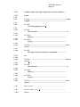
Proposal of amendment to the Regulation No. 83
(Consolidated version)
The document below was prepared by the expert from the European Commission to align the
requirements of the Regulation with those of European Union Directives 715/2007/EC and
692/2008/EC (Euro 5 emissions level).
In order to help the reader to keep track with the changes, the modifications to the current text of the
Regulation, already presented in ECE/TRANS/WP.29/2009/57, are marked in this document in bold
characters. The additional modifications, presented in a Corrigendum (ECE/TRANS/WP.29/2009/53
based on WP.29-149-05), are also marked in bold, but with a grey highlighted characters.
ECE.R.83/06_main
page 2
Regulation No. 83
UNIFORM PROVISIONS CONCERNING THE APPROVAL OF VEHICLES WITH
REGARD TO THE EMISSION OF POLLUTANTS ACCORDING TO ENGINE FUEL
REQUIREMENTS
1.
SCOPE
This Regulation establishes technical requirements for the type approval of motor
vehicles.
In addition, this Regulation lays down rules for in-service conformity, durability
of pollution control devices and on-board diagnostic (OBD) systems.
1.1.
This Regulation shall apply to vehicles of categories M1, M2, N1 and N2 with a
reference mass not exceeding 2,610 kg. 1/
At the manufacturer's request, type approval granted under this Regulation may
be extended from vehicles covered by paragraph 1 to M1, M2, N1 and N2 vehicles
with a reference mass not exceeding 2,840 kg and which meet the conditions laid
down in this Regulation.
1.2.
Equivalent approvals
The following engines do not need to be approved according to this Regulation:
(a) engines mounted in vehicles of up to 2,840 kg reference mass to which an
approval to Regulation No. 83 has been granted as an extension.
2.
DEFINITIONS
For the purposes of this Regulation the following definitions shall apply:
2.1.
"Vehicle type" means a group of vehicles that do not differ in the following
respects:
2.1.1.
the equivalent inertia determined in relation to the reference mass as prescribed in
Annex 4a, Table 3 and
2.1.2.
the engine and vehicle characteristics as defined in Annex 1;
2.2.
"Reference mass" means the mass of the vehicle in running order less the
uniform mass of the driver of 75 kg and increased by a uniform mass of 100 kg
for test according to Annexes 4a and 8,
1
/
As defined in Annex 7 to the Consolidated Resolution on the Construction of Vehicles (R.E.3), (document
TRANS/WP.29/78/Rev.1/Amend.2 as last amended by Amend.4).
ECE.R.83/06_main
page 3
2.2.1.
"Unladen mass" means the mass of the vehicle in running order without the uniform
mass of the driver of 75 kg, passengers or load, but with the fuel tank 90 per cent
full and the usual set of tools and spare wheel on board, where applicable;
2.3.
"Maximum mass" means the technically permissible maximum mass declared by the
vehicle manufacturer (this mass may be greater than the maximum mass authorised
by the national administration);
2.4.
"Gaseous pollutants" means the exhaust gas emissions of carbon monoxide, oxides
of nitrogen, expressed in nitrogen dioxide (NO2) equivalent and hydrocarbons
assuming ratio of:
(a) C1H2.525 for liquefied petroleum gas (LPG)
(b) C1H4 for natural gas (NG) and biomethane
(c) C1H1.89O0.016 for petrol (E5)
(d) C1H1.86O0.005 for diesel (B5)
(e) C1H2.74O0.385 for ethanol (E85)
2.5.
"Particulate pollutants" means components of the exhaust gas which are removed
from the diluted exhaust gas at a maximum temperature of 325 K (52 °C) by means
of the filters described in Annex 4a; Appendix 4;
2.6.
"Exhaust emissions" means emissions of gaseous and particulate pollutants;
2.7.
"Evaporative emissions" means the hydrocarbon vapours lost from the fuel system of
a motor vehicle other than those from exhaust emissions;
2.7.1.
"Tank breathing losses" are hydrocarbon emissions caused by temperature changes in
the fuel tank (assuming a ratio of C1H2.33);
2.7.2.
"Hot soak losses" are hydrocarbon emissions arising from the fuel system of a
stationary vehicle after a period of driving (assuming a ratio of C1 H2.20 );
2.8.
"Engine crankcase" means the spaces in or external to an engine which are connected
to the oil sump by internal or external ducts through which gases and vapour can
escape;
2.9.
"Cold start device" means a device that temporarily enriches the air/fuel mixture of
the engine thus assisting the engine to start;
2.10.
"Starting aid" means a device which assists engine start up without enrichment of the
air/fuel mixture of the engine, e.g. glow plug, injection timing change, etc.;
2.11.
"Engine capacity" means:
2.11.1.
For reciprocating piston engines, the nominal engine swept volume;
2.11.2.
For rotary piston engines (Wankel), twice the nominal swept volume of a combustion
chamber per piston;
ECE.R.83/06_main
page 4
2.12.
"Pollution control devices" means those components of a vehicle that control and/or
limit exhaust and evaporative emissions;
2.13.
"OBD" means an on-board diagnostic system for emission control, which has the
capability of identifying the likely area of malfunction by means of fault codes stored
in computer memory;
2.14.
"In-service test" means the test and evaluation of conformity conducted in
accordance with paragraph 9.2.1. of this Regulation;
2.15.
"Properly maintained and used" means, for the purpose of a test vehicle, that such a
vehicle satisfies the criteria for acceptance of a selected vehicle laid down in
paragraph 2. of Appendix 3 to this Regulation;
2.16.
"Defeat device" means any element of design which senses temperature, vehicle
speed, engine rotational speed, transmission gear, manifold vacuum or any other
parameter for the purpose of activating, modulating, delaying or deactivating the
operation of any part of the emission control system, that reduces the effectiveness of
the emission control system under conditions which may reasonably be expected to
be encountered in normal vehicle operation and use. Such an element of design may
not be considered a defeat device if:
2.16.1.
the need for the device is justified in terms of protecting the engine against damage
or accident and for safe operation of the vehicle, or
2.16.2.
the device does not function beyond the requirements of engine starting, or
2.16.3.
conditions are substantially included in the Type I or Type VI test procedures.
2.17.
"Family of vehicles" means a group of vehicle types identified by a parent vehicle for
the purpose of Annex 12;
2.18.
"Fuel requirement by the engine" means the type of fuel normally used by the
engine:
(a)
Petrol (E5),
(b)
LPG (liquefied petroleum gas)
(c)
NG/biomethane (natural gas)
(d)
Either petrol (E5) or LPG
(e)
Either petrol (E5) or NG/biomethane
(f)
Diesel fuel (B5)
(g)
Mixture of ethanol (E85) and petrol (E5) (Flex fuel)
(h)
Mixture of biodiesel and diesel (B5) (Flex fuel)
(i)
Hydrogen
(j)
Either petrol (E5) or Hydrogen (Bi-fuel)
2.18.1.
"Biofuel" means liquid or gaseous fuel for transport, produced from biomass.
ECE.R.83/06_main
page 5
2.19.
"Approval of a vehicle" means the approval of a vehicle type with regard to the
limitation of the following conditions: 2/
2.19.1.
Limitation of exhaust emissions by the vehicle, evaporative emissions, crankcase
emissions, durability of pollution control devices, cold start pollutant emissions and
on-board diagnostics of vehicles fuelled with unleaded petrol, or which can be
fuelled with either unleaded petrol and LPG or NG/biomethane or biofuels
(Approval B);
2.19.2.
Limitation of emissions of gaseous and particulate pollutants, durability of pollution
control devices and on-board diagnostics of vehicles fuelled with diesel fuel
(Approval C) or which can be fuelled with either diesel fuel and biofuel or
biofuel.
2.19.3.
Limitation of emissions of gaseous pollutants by the engine, crankcase emissions,
durability of pollution control devices, cold start emissions and on-board diagnostics
of vehicles fuelled with LPG or NG/biomethane (Approval D);
2.20.
"Periodically regenerating system" means an anti-pollution device (e.g. catalytic
converter, particulate trap) that requires a periodical regeneration process in less
than 4,000 km of normal vehicle operation. During cycles where regeneration
occurs, emission standards can be exceeded. If a regeneration of an anti-pollution
device occurs at least once per Type I test and that has already regenerated at least
once during vehicle preparation cycle, it will be considered as a continuously
regenerating system which does not require a special test procedure. Annex 13 does
not apply to continuously regenerating systems.
At the request of the manufacturer, the test procedure specific to periodically
regenerating systems will not apply to a regenerative device if the manufacturer
provides data to the type approval authority that, during cycles where regeneration
occurs, emissions remain below the standards given in paragraph 5.3.1.4. applied for
the concerned vehicle category after agreement of the technical service.
2.21.
Hybrid vehicles (HV)
2.21.1.
General definition of hybrid vehicles (HV):
"Hybrid vehicle (HV)" means a vehicle with at least two different energy converters
and two different energy storage systems (on vehicle) for the purpose of vehicle
propulsion.
2.21.2.
2
Definition of hybrid electric vehicles (HEV):
/
Approval A cancelled. From the 05 series of amendments to this Regulation prohibit the use of leaded
petrol.
ECE.R.83/06_main
page 6
"Hybrid electric vehicle (HEV)" means a vehicle that, for the purpose of mechanical
propulsion, draws energy from both of the following on-vehicle sources of stored
energy/power:
(a) a consumable fuel
(b) an electrical energy/power storage device (e.g.: battery, capacitor,
flywheel/generator etc.)
2.22.
"Mono fuel vehicle" means a vehicle that is designed to run primarily on one
type of fuel;
2.22.1.
"Mono-fuel gas vehicle" means a vehicle that is designed primarily for permanent
running on LPG or NG/biomethane or hydrogen, but may also have a petrol system
for emergency purposes or starting only, where the petrol tank does not contain more
than 15 litres of petrol.
2.23.
"Bi-fuel vehicle" means a vehicle with two separate fuel storage systems that can
run part-time on two different fuels and is designed to run on only one fuel at a
time.
2.23.1.
"Bi-fuel gas vehicle" means a bi fuel vehicle that can run on petrol and also on
either LPG, NG/biomethane or hydrogen.
2.24.
"Alternative fuel vehicle" means a vehicle designed to be capable of running on
at least one type of fuel that is either gaseous at atmospheric temperature and
pressure, or substantially non-mineral oil derived.
2.25.
"Flex fuel vehicle" means a vehicle with one fuel storage system that can run on
different mixtures of two or more fuels.
2.25.1.
"Flex fuel ethanol vehicle" means a flex fuel vehicle that can run on petrol or a
mixture of petrol and ethanol up to an 85 per cent ethanol blend (E85).
2.25.2.
"Flex fuel biodiesel vehicle" means a flex fuel vehicle that can run on mineral
diesel or a mixture of mineral diesel and biodiesel.
2.26.
"Vehicles designed to fulfil specific social needs" means diesel vehicles of
category M1 which are either:
(a) Special purpose vehicles with reference mass exceeding 2,000 kg; 3/
(b) Vehicles with a reference mass exceeding 2,000 kg and designed to carry
seven or more occupants including the driver with the exclusion, as from 1
September 2012, of vehicles of category M1G3;
(c) Vehicles with a reference mass exceeding 1,760 kg which are built
specifically for commercial purposes to accommodate wheelchair use
inside the vehicle.
3
/
As defined in Annex 7 to the Consolidated Resolution on the Construction of Vehicles (R.E.3),
(document TRANS/WP.29/78/Rev.1/Amend.2 as last amended by Amend.4).
ECE.R.83/06_main
page 7
3.
APPLICATION FOR APPROVAL
3.1.
The application for approval of a vehicle type with regard to exhaust emissions,
crankcase emissions, evaporative emissions and durability of pollution control
devices, as well as to its on-board diagnostic (OBD) system shall be submitted by the
vehicle manufacturer or by his authorized representative to the approval authority.
3.1.1.
In addition, the manufacturer shall submit the following information:
(a) In the case of vehicles equipped with positive-ignition engines, a
declaration by the manufacturer of the minimum percentage of misfires
out of a total number of firing events that would either result in emissions
exceeding the limits given in paragraph 3.3.2. of Annex 11, if that
percentage of misfire had been present from the start of a Type I test as
described in Annex 4a to this Regulation, or that could lead to an exhaust
catalyst, or catalysts, overheating prior to causing irreversible damage;
(b) Detailed written information fully describing the functional operation
characteristics of the OBD system, including a listing of all relevant parts
of the emission control system of the vehicle that are monitored by the
OBD system;
(c) A description of the malfunction indicator used by the OBD system to
signal the presence of a fault to a driver of the vehicle;
(d) A declaration by the manufacturer that the OBD system complies with the
provisions of paragraph 7. of Appendix 1 to Annex 11 relating to in-use
performance under all reasonably foreseeable driving conditions;
(e) A plan describing the detailed technical criteria and justification for
incrementing the numerator and denominator of each monitor that shall
fulfil the requirements of paragraphs 7.2. and 7.3. of Appendix 1 to
Annex 11, as well as for disabling numerators, denominators and the
general denominator under the conditions outlined in paragraph 7.7. of
Appendix 1 to Annex XI;
(f) A description of the provisions taken to prevent tampering with and
modification of the emission control computer;
(g) If applicable, the particulars of the vehicle family as referred to in
Appendix 2 to Annex 11;
(h) Where appropriate, copies of other type approvals with the relevant data
to enable extension of approvals and establishment of deterioration
factors.
3.1.2.
For the tests described in paragraph 3. of Annex 11, a vehicle representative of the
vehicle type or vehicle family fitted with the OBD system to be approved shall be
submitted to the technical service responsible for the type approval test. If the
technical service determines that the submitted vehicle does not fully represent the
vehicle type or vehicle family described in Annex 11, Appendix 2, an alternative and
if necessary an additional vehicle shall be submitted for test in accordance with
paragraph 3. of Annex 11.
3.2.
A model of the information document relating to exhaust emissions, evaporative
emissions, durability and the on-board diagnostic (OBD) system is given in Annex 1.
ECE.R.83/06_main
page 8
The information mentioned under paragraph 3.2.12.2.7.6. of Annex 1 is to be
included in Appendix 1 "OBD - RELATED INFORMATION" to the type approval
communication given in Annex 2.
3.2.1.
Where appropriate, copies of other type approvals with the relevant data to enable
extensions of approvals and establishment of deterioration factors shall be submitted.
3.3.
For the tests described in paragraph 5. of this Regulation a vehicle representative of
the vehicle type to be approved shall be submitted to the technical service
responsible for the approval tests.
3.4.1.
The application referred to in paragraph 3.1. shall be drawn up in accordance
with the model of the information document set out in Annex 1.
3.4.2
For the purposes of paragraph 3.1.1.(d), the manufacturer shall use the model
of a manufacturer's certificate of compliance with the OBD in-use performance
requirements set out in Appendix 2 of Annex 2.
3.4.3.
For the purposes of paragraph 3.1.1.(e), the approval authority that grants the
approval shall make the information referred to in that point available to the
approval authorities upon request.
3.4.5.
For the purposes of points (d) and (e) of paragraph 3.1.1., approval authorities
shall not approve a vehicle if the information submitted by the manufacturer is
inappropriate for fulfilling the requirements of paragraph 7. of Appendix 1 to
Annex 11. Paragraphs 7.2., 7.3. and 7.7. of Appendix 1 to Annex 11 shall apply
under all reasonably foreseeable driving conditions. For the assessment of the
implementation of the requirements set out in the first and second
subparagraphs, the approval authorities shall take into account the state of
technology.
3.4.6.
For the purposes of paragraph 3.1.1.(f), the provisions taken to prevent
tampering with and modification of the emission control computer shall include
the facility for updating using a manufacturer-approved programme or
calibration.
3.4.7.
For the tests specified in Table A, the manufacturer shall submit to the technical
service responsible for the type approval tests a vehicle representative of the
type to be approved.
3.4.8.
The application for type approval of mono fuel, bi-fuel and flex-fuel vehicles
shall comply with the additional requirements laid down in paragraphs 4.9.1
and 4.9.2.
3.4.9.
Changes to the make of a system, component or separate technical unit that
occur after a type approval shall not automatically invalidate a type approval,
unless its original characteristics or technical parameters are changed in such a
way that the functionality of the engine or pollution control system is affected.
ECE.R.83/06_main
page 9
4.
APPROVAL
4.1.
If the vehicle type submitted for approval following this amendment meets the
requirements of paragraph 5. below, approval of that vehicle type shall be granted.
4.2.
An approval number shall be assigned to each type approved.
Its first two digits shall indicate the series of amendments according to which the
approval was granted. The same Contracting Party shall not assign the same number
to another vehicle type.
4.3.
Notice of approval or of extension or refusal of approval of a vehicle type pursuant to
this Regulation shall be communicated to the Parties to the Agreement which apply
this Regulation by means of a form conforming to the model in Annex 2 to this
Regulation.
4.3.1.
In the event of amendment to the present text, for example, if new limit values are
prescribed, the Parties to the Agreement shall be informed which vehicle types
already approved comply with the new provisions.
4.4.
There shall be affixed, conspicuously and in a readily accessible place specified on
the approval form, to every vehicle conforming to a vehicle type approved under this
Regulation, an international approval mark consisting of:
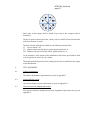
4.4.1.
A circle surrounding the letter "E" followed by the distinguishing number of the
country that has granted approval; 4/
4
/
1 for Germany, 2 for France, 3 for Italy, 4 for the Netherlands, 5 for Sweden, 6 for
Belgium, 7 for Hungary, 8 for the Czech Republic, 9 for Spain, 10 for Serbia and Montenegro,
11 for the United Kingdom, 12 for Austria, 13 for Luxembourg, 14 for Switzerland, 15 (vacant),
16 for Norway, 17 for Finland, 18 for Denmark, 19 for Romania, 20 for Poland, 21 for Portugal,
22 for the Russian Federation, 23 for Greece, 24 for Ireland, 25 for Croatia, 26 for Slovenia,
27 for Slovakia, 28 for Belarus, 29 for Estonia, 30 (vacant), 31 for Bosnia and Herzegovina,
32 for Latvia, 33 (vacant), 34 for Bulgaria, 35 (vacant), 36 for Lithuania, 37 for Turkey,
38 (vacant), 39 for Azerbaijan, 40 for The former Yugoslav Republic of Macedonia, 41 (vacant),
42 for the European Community (Approvals are granted by its Member States using their
respective ECE symbol), 43 for Japan, 44 (vacant), 45 for Australia, 46 for Ukraine, 47 for South
Africa, 48 for New Zealand, 49 for Cyprus, 50 for Malta, 51 for the Republic of Korea, 52 for
Malaysia, 53 for Thailand, 54 and 55 (vacant), 56 for Montenegro, 57 (Vacant) and 58 for
Tunisia. Subsequent numbers shall be assigned to other countries in the chronological order in
which they ratify or accede to the Agreement Concerning the Adoption of Uniform Technical
Prescriptions for Wheeled Vehicles, Equipment and Parts which can be Fitted and/or be Used on
Wheeled Vehicles and the Conditions for Reciprocal Recognition of Approvals Granted on the
Basis of these Prescriptions, and the numbers thus assigned shall be communicated by the
Secretary-General of the United Nations to the Contracting Parties to the Agreement.
ECE.R.83/06_main
page 10
4.4.2.
The number of this Regulation, followed by the letter "R", a dash and the approval
number to the right of the circle described in paragraph 4.4.1.;
4.4.3.
The approval mark shall contain an additional character after the type approval
number, the purpose of which is to distinguish vehicle category and class for which
the approval has been granted. This letter should be chosen according to the Table
1 in Annex 3 to this Regulation.
4.5.
If the vehicle conforms to a vehicle type approved, under one or more other
Regulations annexed to the Agreement, in the country which has granted approval
under this Regulation, the symbol prescribed in paragraph 4.4.1. need not be
repeated; in such a case, the Regulation and approval numbers and the additional
symbols of all the Regulations under which approval has been granted in the country
which has granted approval under this Regulation shall be placed in vertical columns
to the right of the symbol prescribed in paragraph 4.4.1.
4.6.
The approval mark shall be clearly legible and be indelible.
4.7.
The approval mark shall be placed close to or on the vehicle data plate.
4.8.
Annex 3 to this Regulation gives examples of arrangements of the approval mark.
4.9.
ADDITIONAL REQUIREMENTS FOR APPROVAL OF FLEX FUEL
VEHICLES
4.9.1.
For the type approval of a flex fuel ethanol or biodiesel vehicle, the vehicle
manufacturer shall describe the capability of the vehicle to adapt to any mixture
of petrol and ethanol fuel (up to an 85 per cent ethanol blend) or diesel and
biodiesel that may occur across the market.
4.9.2.
For flex fuel vehicles, the transition from one reference fuel to another between
the tests shall take place without manual adjustment of the engine settings.
4.10.
REQUIREMENTS FOR APPROVAL REGARDING THE OBD SYSTEM
4.10.1.
The manufacturer shall ensure that all vehicles are equipped with an OBD
system.
4.10.2.
The OBD system shall be designed, constructed and installed on a vehicle so as
to enable it to identify types of deterioration or malfunction over the entire life
of the vehicle.
4.10.3.
The OBD system shall comply with the requirements of this Regulation during
conditions of normal use.
4.10.4.
When tested with a defective component in accordance with Appendix 1 of
Annex 11, the OBD system malfunction indicator shall be activated. The OBD
ECE.R.83/06_main
page 11
system malfunction indicator may also activate during this test at levels of
emissions below the OBD threshold limits specified in Annex 11.
4.10.5.
The manufacturer shall ensure that the OBD system complies with the
requirements for in-use performance set out in paragraph 7. of Appendix 1 to
Annex 11 of this Regulation under all reasonably foreseeable driving conditions.
4.10.6.
In-use performance related data to be stored and reported by a vehicle's OBD
system according to the provisions of item 7.6. of Appendix 1 to Annex 11 shall
be made readily available by the manufacturer to national authorities and
independent operators without any encryption.
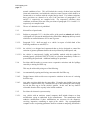
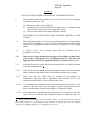
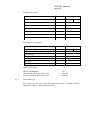
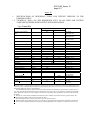
5.
SPECIFICATIONS AND TESTS
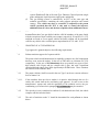
Small volume manufacturers
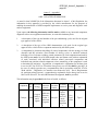
As an alternative to the requirements of this paragraph, vehicle manufacturers
whose world-wide annual production is less than 10,000 units may obtain
approval on the basis of the corresponding technical requirements specified in
the table below.
Legislative Act
The California Code of Regulations,
Title 13, paragraphs 1961(a) and
1961(b)(1)(C)(1) applicable to 2001 and
later model year vehicles, 1968.1, 1968.2,
1968.5, 1976 and 1975, published by
Barclay's Publishing.
Requirements
Type approval shall be granted
under the California Code of
Regulations applicable to the most
recent model year of light duty
vehicle.
The emissions tests for roadworthiness purposes set out in Annex 5 and the
requirements for access to vehicle OBD information set out in paragraph 5. of
Annex 11 shall still be required to obtain type approval with regard to emissions
under this paragraph.
The approval authority shall inform the other approval authorities of
Contracting Parties of the circumstances of each type approval granted under
this paragraph.
5.1.
General
5.1.1.
The components liable to affect the emission of pollutants shall be so designed,
constructed and assembled as to enable the vehicle, in normal use, despite the
vibration to which they may be subjected, to comply with the provisions of this
Regulation.
5.1.2.
The technical measures taken by the manufacturer shall be such as to ensure that in
conformity with the provisions of this Regulation, exhaust gas and evaporative
emissions are effectively limited throughout the normal life of the vehicle and under
ECE.R.83/06_main
page 12
normal conditions of use. This will include the security of those hoses and their
joints and connections, used within the emission control systems, which shall be so
constructed as to conform with the original design intent. For exhaust emissions,
these provisions are deemed to be met if the provisions of paragraphs 5.3.1.4.
and 8.2.3.1. respectively are complied with. For evaporative emissions, these
conditions are deemed to be met if the provisions of paragraphs 5.3.1.4. and 8.2.3.1.
respectively are complied with.
5.1.2.1.
The use of a defeat device is prohibited.
5.1.3.
Inlet orifices of petrol tanks
5.1.3.1.
Subject to paragraph 5.1.3.2., the inlet orifice of the petrol or ethanol tank shall be
so designed as to prevent the tank from being filled from a fuel pump delivery nozzle
which has an external diameter of 23.6 mm or greater.
5.1.3.2.
Paragraph 5.1.3.1. shall not apply to a vehicle in respect of which both of the
following conditions are satisfied, i.e.:
5.1.3.2.1. the vehicle is so designed and constructed that no device designed to control the
emission of gaseous pollutants shall be adversely affected by leaded petrol, and;
5.1.3.2.2. the vehicle is conspicuously, legibly and indelibly marked with the symbol for
unleaded petrol, specified in ISO 2575:1982, in a position immediately visible to a
person filling the petrol tank. Additional markings are permitted.
5.1.4.
Provision shall be made to prevent excess evaporative emissions and fuel spillage
caused by a missing fuel filler cap.
This may be achieved by using one of the following:
5.1.4.1.
An automatically opening and closing, non-removable fuel filler cap;
5.1.4.2.
Design features which avoid excess evaporative emissions in the case of a missing
fuel filler cap;
5.1.4.3.
Any other provision which has the same effect. Examples may include, but are not
limited to, a tethered filler cap, a chained filler cap or one utilising the same locking
key for the filler cap as for the vehicle's ignition. In this case, the key shall be
removable from the filler cap only in the locked condition.
5.1.5.
Provisions for electronic system security
5.1.5.1.
Any vehicle with an emission control computer shall include features to deter
modification, except as authorised by the manufacturer. The manufacturer shall
authorise modifications if these modifications are necessary for the diagnosis,
servicing, inspection, retrofitting or repair of the vehicle. Any reprogrammable
computer codes or operating parameters shall be resistant to tampering and afford a
ECE.R.83/06_main
page 13
level of protection at least as good as the provisions in ISO DIS 15031-7, dated
October 1998 (SAE J2186 dated October 1996), provided that the security exchange
is conducted using the protocols and diagnostic connector as prescribed in
paragraph 6.5. of Annex 11, Appendix 1. Any removable calibration memory chips
shall be potted, encased in a sealed container or protected by electronic algorithms
and shall not be changeable without the use of specialised tools and procedures.
5.1.5.2.
Computer-coded engine operating parameters shall not be changeable without the
use of specialised tools and procedures (e.g. soldered or potted computer components
or sealed (or soldered) computer enclosures).
5.1.5.3.
In the case of mechanical fuel-injection pumps fitted to compression-ignition
engines, manufacturers shall take adequate steps to protect the maximum fuel
delivery setting from tampering while a vehicle is in service.
5.1.5.4.
Manufacturers may apply to the approval authority for an exemption to one of these
requirements for those vehicles which are unlikely to require protection. The criteria
that the approval authority will evaluate in considering an exemption will include,
but are not limited to, the current availability of performance chips, the highperformance capability of the vehicle and the projected sales volume of the vehicle.
5.1.5.5.
Manufacturers using programmable computer code systems (e.g. Electrical Erasable
Programmable Read-Only Memory, EEPROM) shall deter unauthorised
reprogramming. Manufacturers shall include enhanced tamper protection strategies
and write protect features requiring electronic access to an off-site computer
maintained by the manufacturer. Methods giving an adequate level of tamper
protection will be approved by the authority.
5.1.6.
It shall be possible to inspect the vehicle for roadworthiness test in order to
determine its performance in relation to the data collected in accordance with
paragraph 5.3.7. of this Regulation. If this inspection requires a special procedure,
this shall be detailed in the service manual (or equivalent media). This special
procedure shall not require the use of special equipment other than that provided with
the vehicle
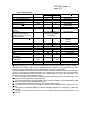
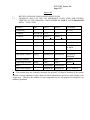
5.2.
Test procedure
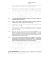
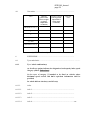
Table A illustrates the various possibilities for type approval of a vehicle.
5.2.1.
Positive ignition engine-powered vehicles and hybrid electric vehicles equipped with
a positive-ignition engine shall be subject to the following tests:
Type I (verifying the average exhaust emissions after a cold start),
Type II (carbon monoxide emission at idling speed),
Type III (emission of crankcase gases),
ECE.R.83/06_main
page 14
Type IV (evaporation emissions),
Type V (durability of anti-pollution devices),
Type VI (verifying the average low ambient temperature carbon monoxide and
hydrocarbon exhaust emissions after a cold start,
OBD-test.
5.2.2.
Positive ignition engine-powered vehicle and hybrid electric vehicles equipped with
positive-ignition engine fuelled with LPG or NG/biomethane (mono or bi-fuel) shall
be subjected to the following tests (according to Table A):
Type I (verifying the average exhaust emissions after a cold start),
Type II (carbon monoxide emissions at idling speed),
Type III (emission of crankcase gases),
Type IV (evaporative emissions), where applicable,
Type V (durability of anti-pollution devices),
Type VI (verifying the average low ambient temperature carbon monoxide and
hydrocarbon exhaust emissions after a cold start), where applicable,
OBD test.
5.2.3.
Compression ignition engine-powered vehicles and hybrid electric vehicles equipped
with a compression ignition engine shall be subject to the following tests:
Type I (verifying the average exhaust emissions after a cold start)
Type V (durability of anti-pollution control devices)
and OBD test.
ECE.R.83/06_main
page 15
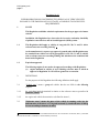
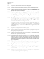
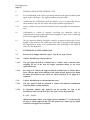
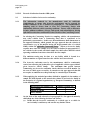
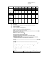
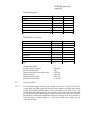
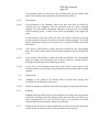
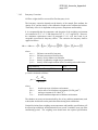
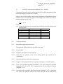
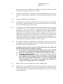
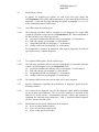
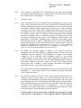
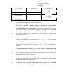
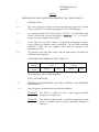
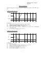
Table A. REQUIREMENTS
Application of test requirements for type approval and extensions
Vehicles with positive ignition engines including hybrids
Bi fuel(1)
Mono fuel
Reference fuel Petrol (E5) LPG
Gaseous
pollutants
(Type I test)
Particulates
(Type I test)
Yes
NG/
Hydrogen Petrol (E5) Petrol (E5)
Biomethane
LPG
NG/
Biomethane
Yes
Yes
Yes
Yes
(both fuels) (both fuels)
Yes
(direct
injection)
-
-
Idle emissions
(Type II test)
Yes
Yes
Yes
Crankcase
emissions
(Type III test)
Evaporative
emissions
(Type IV test)
Durability
(Type V test)
Yes
Yes
Yes
Low
temperature
emissions
(Type VI test)
In-service
conformity
Yes
Yes
Yes
Yes
Yes
-
Yes
Yes
-
Yes
Yes
Yes
(direct
(direct
injection) injection)
(petrol (petrol only)
only)
Yes
Yes
(both fuels) (both fuels)
Yes
(petrol
only)
Yes
(petrol
only)
Yes
(petrol
only)
Yes
(petrol
only)
Yes
(petrol only)
Yes
(petrol only)
Yes
(petrol only)
Yes
(petrol only)
Yes
Yes
(both fuels) (both fuels)
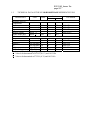
Vehicles with C.I.
engines including
hybrids
Flex
Flex fuel Mono
fuel(1)
fuel
Petrol (E5) Petrol
Diesel Diesel
(E5)
(B5)
(B5)
Hydrogen Ethanol Biodiesel
(E85)
Yes
Yes
Yes (B5
Yes
(petrol
(both
only)(2)
only)(2)
fuels)
Yes
Yes (B5
Yes
Yes
(direct
only)(2)
(direct
injection) injection)
(petrol
(both
only)(2)
fuels)
Yes
Yes
(petrol
(both
only)(2)
fuels)
Yes
Yes
(petrol
(petrol)
only)(2)
Yes
(petrol
only)(2)
Yes
(petrol
only)(2)
Yes
(petrol
only)(2)
Yes
(petrol
only)(2)
Yes
(petrol)
-
-
Yes
(petrol)
Yes (B5
only)(2)
Yes
Yes (both
fuels)(3
-
-
Yes
(both
fuels)
Yes
Yes (B5
only)(2)
Yes
On-board
Yes
Yes
Yes
Yes
Yes
Yes
Yes (B5
Yes
diagnostics
only)(2)
(1)
When a bi fuel vehicle is combined with a flex fuel vehicle, both test requirements are applicable.
(2)
This provision is temporary, further requirements for biodiesel and hydrogen shall be proposed later on.
(3)
For this test, fuel applicable to low ambient temperatures should be used. In the absence of a winter grade
reference fuel specification, the applicable winter grade fuel for this test should be agreed between the approval
authority and the manufacturer according to the existing market specifications.
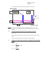
5.3.
Description of tests
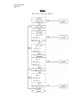
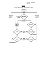
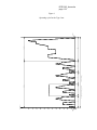
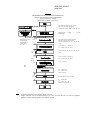
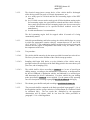
5.3.1.
Type I test (Simulating the average exhaust emissions after a cold start).
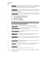
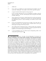
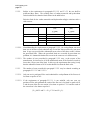
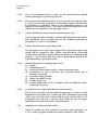
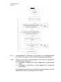
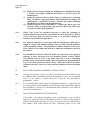
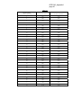
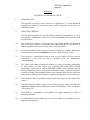
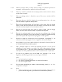
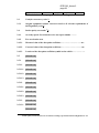
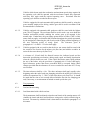
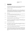
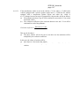
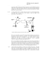
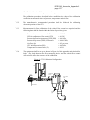
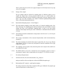
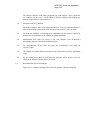
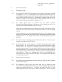
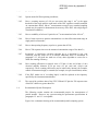
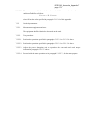
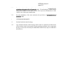
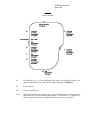
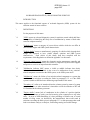
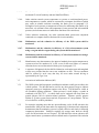
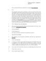
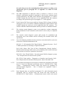
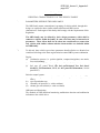
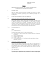
5.3.1.1.
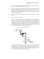
Figure 1 illustrates the routes for Type I test. This test shall be carried out on all
vehicles referred to in paragraph 1. and its sub-paragraphs.
5.3.1.2.
The vehicle is placed on a chassis dynamometer equipped with a means of load and
inertia simulation.
ECE.R.83/06_main
page 16
5.3.1.2.1. A test lasting a total of 19 minutes and 40 seconds, made up of two parts, One and
Two, is performed without interruption. An unsampled period of not more
than 20 seconds may, with the agreement of the manufacturer, be introduced between
the end of Part One and the beginning of Part Two in order to facilitate adjustment of
the test equipment.
5.3.1.2.1.1. Vehicles that are fuelled with LPG or NG/biomethane shall be tested in the Type I
test for variation in the composition of LPG or NG/biomethane, as set out in
Annex 12. Vehicles that can be fuelled either with petrol or LPG or NG/biomethane
shall be tested on both the fuels, tests on LPG or NG/biomethane being performed
for variation in the composition of LPG or NG/biomethane, as set out in Annex 12.
5.3.1.2.1.2. Notwithstanding the requirement of paragraph 5.3.1.2.1.1., vehicles that can be
fuelled with either petrol or a gaseous fuel, but where the petrol system is fitted for
emergency purposes or starting only and which the petrol tank cannot contain more
than 15 litres of petrol will be regarded for the test Type I as vehicles that can only
run on a gaseous fuel.
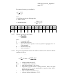
5.3.1.2.2. Part One of the test is made up of four elementary urban cycles. Each elementary
urban cycle comprises fifteen phases (idling, acceleration, steady speed, deceleration,
etc.).
5.3.1.2.3. Part Two of the test is made up of one extra-urban cycle. The extra-urban cycle
comprises 13 phases (idling, acceleration, steady speed, deceleration, etc.).
5.3.1.2.4. During the test, the exhaust gases are diluted and a proportional sample collected in
one or more bags. The exhaust gases of the vehicle tested are diluted, sampled and
analysed, following the procedure described below, and the total volume of the
diluted exhaust is measured. Not only the carbon monoxide, hydrocarbon and
nitrogen oxide emissions but also the particulate pollutant emissions from vehicles
equipped with compression-ignition engines are recorded.
5.3.1.3.
The test is carried out using Type I test as described in Annex 4a. The method used
to collect and analyse the gases is prescribed in Appendix 2 and 3 of Annex 4a,
and the method to sample and analyse the particulates shall be as prescribed in
Appendix 4 and 5 of Annex 4a.
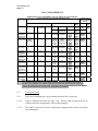
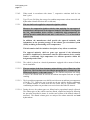
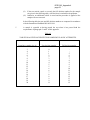
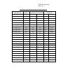
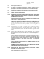
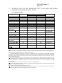
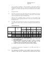
5.3.1.4.
Subject to the requirements of paragraph 5.3.1.5. the test shall be repeated three
times. The results are multiplied by the appropriate deterioration factors obtained
from paragraph 5.3.6. and, in the case of periodically regenerating systems as defined
in paragraph 2.20., also shall be multiplied by the factors Ki obtained from Annex 13.
The resulting masses of gaseous emissions and, in the case of vehicles equipped with
compression-ignition engines, the particulates obtained in each test shall be less than
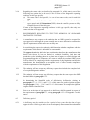
the limits shown in the Table 1. below:
ECE.R.83/06_main
page 17
Emissions limits
Limit values
Reference mass
(RM)
(kg)
Mass of nonMass of carbon Mass of total
methane
monoxide
hydrocarbons
hydrocarbons
(CO)
(THC)
(NMHC)
Mass of
oxides of
nitrogen
(NOx)
TRANS/WP.29/GRPE/2003/
8
page 17
Table 1:
Combined mass
of hydrocarbons Mass of particulate
Number of particles
and oxides of
matter
(P)
nitrogen
(PM)
(THC + NOx)
L2 + L 3
L5
L6
(mg/km)
(mg/km)
(number/km)
PI
CI
PI (3)
CI
PI
CI
230
4.5
4.5
6.0 x 10¹¹
230
4.5
4.5
6.0 x 10¹¹
295
4.5
4.5
6.0 x 10¹¹
350
4.5
4.5
6.0 x 10¹¹
350
4.5
4.5
6.0 x 10¹¹
L1
L4
L2
L3
(mg/km)
(mg/km)
(mg/km)
(mg/km)
Category Class
PI
CI
PI
CI
PI
CI
PI
CI
M
All
1,000 500
100
68
60 180
I
RM ≤ 1,305
1,000 500
100
68
60 180
N1
II 1,305 < RM ≤ 1,760 1,810 630
130
90
75 235
III 1,760 < RM
2,270 740
160
108
82 280
N2
All
2,270 740
160
108
82 280
Key: PI = Positive Ignition, CI = Compression Ignition
(1)
Positive ignition particulate mass standard shall apply only to vehicles with direct injection engines.
ECE/TRANS/WP.29/2009/5
7
page 17
ECE.R.83/06_main
page 18
5.3.1.4.1. Notwithstanding the requirements of paragraph 5.3.1.4., for each pollutant or
combination of pollutants, one of the three resulting masses obtained may exceed, by
not more than 10 per cent, the limit prescribed, provided the arithmetical mean of the
three results is below the prescribed limit. Where the prescribed limits are exceeded
for more than one pollutant, it is immaterial whether this occurs in the same test or in
different tests.
5.3.1.4.2. When the tests are performed with gaseous fuels, the resulting mass of gaseous
emissions shall be less than the limits for petrol-engined vehicles in the above table.
5.3.1.5.
The number of tests prescribed in paragraph 5.3.1.4. is reduced in the conditions
hereinafter defined, where V1 is the result of the first test and V2 the result of the
second test for each pollutant or for the combined emission of two pollutants subject
to limitation.
5.3.1.5.1. Only one test is performed if the result obtained for each pollutant or for the
combined emission of two pollutants subject to limitation, is less than or equal
to 0.70 L (i.e. V1 ≤ 0.70 L).
5.3.1.5.2. If the requirement of paragraph 5.3.1.5.1. is not satisfied, only two tests are
performed if, for each pollutant or for the combined emission of two pollutants
subject to limitation, the following requirements are met:
V1 ≤ 0.85 L and V1 + V2 ≤1.70 L and V2 ≤ L.
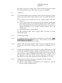
ECE.R.83/06_main
page 19
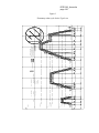
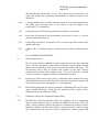
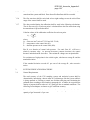
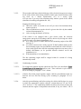
Figure 1
Flow chart for Type I type approval
(see paragraph 5.3.1.)
ECE.R.83/06_main
page 20
5.3.2.
Type II test (Carbon monoxide emission test at idling speed)
5.3.2.1.
This test is carried out on all vehicles powered by positive-ignition engines having:
5.3.2.1.1. Vehicles that can be fuelled either with petrol or with LPG or NG/biomethane shall
be tested in the test Type II on both fuels.
5.3.2.1.2. Notwithstanding the requirement of paragraph 5.3.2.1.1., vehicles that can be fuelled
with either petrol or a gaseous fuel, but where the petrol system is fitted for
emergency purposes or starting only and which the petrol tank cannot contain more
than 15 litres of petrol will be regarded for the test Type II as vehicles that can only
run on a gaseous fuel.
5.3.2.2.
For the Type II test set out in Annex 5, at normal engine idling speed, the
maximum permissible carbon monoxide content in the exhaust gases shall be
that stated by the vehicle manufacturer. However, the maximum carbon
monoxide content shall not exceed 0.3 per cent vol.
At high idle speed, the carbon monoxide content by volume of the exhaust gases
shall not exceed 0.2 per cent, with the engine speed being at least 2,000 min-1
and Lambda being 1 ± 0.03 or in accordance with the specifications of the
manufacturer.
5.3.3.
Type III test (verifying emissions of crankcase gases)
5.3.3.1.
This test shall be carried out on all vehicles referred to in paragraph 1. except those
having compression-ignition engines.
5.3.3.1.1. Vehicles that can be fuelled either with petrol or with LPG or NG/biomethane should
be tested in the Type III test on petrol only.
5.3.3.1.2. Notwithstanding the requirement of paragraph 5.3.3.1.1., vehicles that can be fuelled
with either petrol or a gaseous fuel, but where the petrol system is fitted for
emergency purposes or starting only and which the petrol tank cannot contain more
than 15 litres of petrol will be regarded for the test Type III as vehicles that can only
run on a gaseous fuel.
5.3.3.2.
When tested in accordance with Annex 6, the engine's crankcase ventilation system
shall not permit the emission of any of the crankcase gases into the atmosphere.
5.3.4.
Type IV test (Determination of evaporative emissions)
5.3.4.1.
This test shall be carried out on all vehicles referred to in paragraph 1. except those
vehicles having a compression-ignition engine, vehicles fuelled with LPG or
NG/biomethane.
5.3.4.1.1. Vehicles that can be fuelled either with petrol or with LPG or with NG/biomethane
should be tested in the Type IV test on petrol only.
ECE.R.83/06_main
page 21
5.3.4.2.
When tested in accordance with Annex 7, evaporative emissions shall be less
than 2 g/test.
5.3.5.
Type VI test (Verifying the average low ambient temperature carbon monoxide and
hydrocarbon exhaust emissions after a cold start).
5.3.5.1.
This test shall not be applied to compression ignition vehicles.
However, for compression ignition vehicles when applying for type approval,
manufacturers shall present to the approval authority information showing that
the NOX aftertreatment device reaches a sufficiently high temperature for
efficient operation within 400 seconds after a cold start at –7 °C as described in
Type VI test.
In addition, the manufacturer shall provide the approval authority with
information on the operating strategy of the exhaust gas recirculation system
(EGR), including its functioning at low temperatures.
This information shall also include a description of any effects on emissions.
The approval authority shall not grant type approval if the information
provided is insufficient to demonstrate that the aftertreatment device actually
reaches a sufficiently high temperature for efficient operation within the
designated period of time.
5.3.5.1.1. The vehicle is placed on a chassis dynamometer equipped with a means of load an
inertia simulation.
5.3.5.1.2. The test consists of the four elementary urban driving cycles of Part One of the
Type I test. The Part One test is described in paragraph 6.1.1. of Annex 4a, and
illustrated in figure 1 of the same Annex. The low ambient temperature test lasting
a total of 780 seconds shall be carried out without interruption and start at engine
cranking.
5.3.5.1.3. The low ambient temperature test shall be carried out at an ambient test temperature
of 266 K (-7°C). Before the test is carried out, the test vehicles shall be conditioned
in a uniform manner to ensure that the test results may be reproducible. The
conditioning and other test procedures are carried out as described in Annex 8.
5.3.5.1.4. During the test, the exhaust gases are diluted and a proportional sample collected.
The exhaust gases of the vehicle tested are diluted, sampled and analysed, following
the procedure described in Annex 8, and the total volume of the diluted exhaust is
measured. The diluted exhaust gases are analysed for carbon monoxide and total
hydrocarbons.
ECE.R.83/06_main
page 22
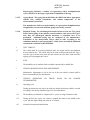
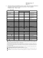
5.3.5.2.
Subject to the requirements in paragraphs 5.3.5.2.2. and 5.3.5.3. the test shall be
performed three times. The resulting mass of carbon monoxide and hydrocarbon
emission shall be less than the limits shown in the table below:
Emission limit for the carbon monoxide and hydrocarbon tailpipe emissions after a
cold start test
Test temperature 266 K (-7 °C)
Vehicle catgory
Class
Mass of carbon monoxide
(CO)
Mass of hydrocarbons
(HC)
L1 (g/km)
L2 (g/km)
M
-
15
1.8
N1
I
15
1.8
N2
II
24
2.7
III
30
3.2
-
30
3.2
5.3.5.2.1. Notwithstanding the requirements of paragraph 5.3.5.2., for each pollutant, not more
than one of the three results obtained may exceed the limit prescribed by not more
than 10 per cent, provided the arithmetical mean value of the three results is below
the prescribed limit. Where the prescribed limits are exceeded for more than one
pollutant, it is immaterial whether this occurs in the same test or in different tests.
5.3.5.2.2. The number of tests prescribed in paragraph 5.3.5.2. may, at the request of the
manufacturer, be increased to 10 if the arithmetical mean of the first three results is
lower than 110 per cent of the limit. In this case, the requirement after testing is only
that the arithmetical mean of all 10 results shall be less than the limit value.
5.3.5.3.
The number of tests prescribed in paragraph 5.3.5.2. may be reduced according to
paragraphs 5.3.5.3.1. and 5.3.5.3.2.
5.3.5.3.1. Only one test is performed if the result obtained for each pollutant of the first test is
less than or equal to 0.70 L.
5.3.5.3.2. If the requirement of paragraph 5.3.5.3.1. is not satisfied, only two tests are
performed if for each pollutant the result of the first test is less than or equal to 0.85
L and the sum of the first two results is less than or equal to 1.70 L and the result of
the second test is less than or equal to L.
(V1 ≤ 0.85 L and V1 + V2 ≤ 1.70 L and V2 ≤ L).
ECE.R.83/06_main
page 23
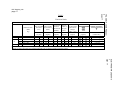
5.3.6.
Type V test (Durability of anti-pollution devices)
5.3.6.1.
This test shall be carried out on all vehicles referred to in paragraph 1 to which the
test specified in paragraph 5.3.1. applies. The test represents an ageing test
of 160,000 kilometres driven in accordance with the programme described in
Annex 9 on a test track, on the road or on a chassis dynamometer.
5.3.6.1.1. Vehicles that can be fuelled either with petrol or with LPG or NG should be tested in
the Type V test on petrol only. In that case the deterioration factor found with
unleaded petrol will also be taken for LPG or NG.
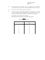
5.3.6.2.
Notwithstanding the requirement of paragraph 5.3.6.1., a manufacturer may choose
to have the deterioration factors from the following table used as an alternative to
testing to paragraph 5.3.6.1.
Engine
Category
Positiveignition
Compression
-ignition
Assigned deterioration factors
CO
THC
NMHC
NOx
HC + NOx
1.5
1.3
1.3
1.6
1.5
-
-
1.1
Particles
-
Particulate
Matter (PM)
1.0
1.1
1.0
1.0
1.0
At the request of the manufacturer, the technical service may carry out the Type I test
before the Type V test has been completed using the deterioration factors in the table
above. On completion of the Type V test, the technical service may then amend the
type approval results recorded in Annex 2 by replacing the deterioration factors in
the above table with those measured in the Type V test.
5.3.6.3.
Deterioration factors are determined using either procedure in paragraph 5.3.6.1. or
using the values in the table in paragraph 5.3.6.2. The factors are used to establish
compliance with the requirements of paragraphs 5.3.1.4. and 8.2.3.1.
5.3.7.
Emission data required for roadworthiness testing
5.3.7.1.
This requirement applies to all vehicles powered by a positive-ignition engine for
which type approval is sought in accordance with this amendment.
5.3.7.2.
When tested in accordance with Annex 5 (Type II test) at normal idling speed:
(a) The carbon monoxide content by volume of the exhaust gases emitted shall be
recorded;
(b) The engine speed during the test shall be recorded, including any tolerances.
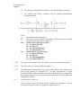
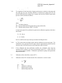
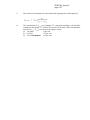
5.3.7.3.
When tested at 'high idle' speed (i. e. > 2,000 min )
(a) The carbon monoxide content by volume of the exhaust gases emitted shall be
recorded;
(b) The Lambda value (*) shall be recorded;
-1
ECE.R.83/06_main
page 24
(c)
The engine speed during the test shall be recorded, including any tolerances.
(*)
The Lambda value shall be calculated using the simplified Brettschneider
equation as follows:
where:
[]=
Concentration in per cent volume
K1 =
Conversion factor for NDIR measurement to FID measurement (provided
by manufacturer of measuring equipment)
Hcv = Atomic ratio of hydrogen to carbon
(a) for petrol (E5) 1.89
(b) for LPG 2.53
(c) for NG/biomethane 4.0
(d) for ethanol (E85) 2.74
Ocv = Atomic ratio of oxygen to carbon
(a) for petrol (E5) 0.016
(b) for LPG 0.0
(c) for NG/biomethane 0.0
(d) for ethanol (E85) 0.39
5.3.7.4.
The engine oil temperature at the time of the test shall be measured and recorded.
5.3.7.5.
The table in item 17 to Annex 2 shall be completed.
5.3.7.6.
The manufacturer shall confirm the accuracy of the Lambda value recorded at the
time of type approval in paragraph 5.3.7.3. as being representative of typical
production vehicles within 24 months of the date of the granting of type approval by
the competent authority. An assessment shall be made based on surveys and studies
of production vehicles.
5.3.8.
On-board diagnostics (OBD) - test
This test shall be carried out on all vehicles referred to in paragraph 1. The test
procedure described in Annex 11, paragraph 3. shall be followed.
ECE.R.83/06_main
page 25
6.
MODIFICATIONS OF THE VEHICLE TYPE
6.1.
Every modification of the vehicle type shall be notified to the approval authority that
approved the vehicle type. The approval authority may then either:
6.1.1.
consider that the modifications made are unlikely to have an appreciable adverse
effect and that in any case the vehicle still complies with the requirement; or
6.1.2.
require a further test report from the technical service responsible for conducting the
tests.
6.2.
Confirmation or refusal of approval, specifying the alterations, shall be
communicated by the procedure specified in paragraph 4.3. above to the Contracting
Parties which apply this Regulation.
6.3.
The type approval authority issuing the extension of approval shall assign a series
number to the extension and inform thereof the other Contracting Parties applying
this Regulation by means of a communication form conforming to the model in
Annex 2 to this Regulation.
7.
EXTENSIONS TO TYPE APPROVALS
7.1.
Extensions for tailpipe emissions (Type I, Type II and Type VI tests)
7.1.1.
Vehicles with different reference masses
7.1.1.1.
The type approval shall be extended only to vehicles with a reference mass
requiring the use of the next two higher equivalent inertia or any lower
equivalent inertia.
7.1.1.2.
For category N vehicles, the approval shall be extended only to vehicles with a
lower reference mass, if the emissions of the vehicle already approved are within
the limits prescribed for the vehicle for which extension of the approval is
requested.
7.1.2.
Vehicles with different overall transmission ratios
7.1.2.1.
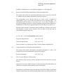
The type approval shall be extended to vehicles with different transmission
ratios only under certain conditions.
7.1.2.2.
To determine whether type approval can be extended, for each of the
transmission ratios used in the Type I and Type VI tests, the proportion,
E = |(V2 − V1)|/V1
shall be determined where, at an engine speed of 1,000 min-1, V1 is the speed of
the type of vehicle approved and V2 is the speed of the vehicle type for which
extension of the approval is requested.
ECE.R.83/06_main
page 26
7.1.2.3.
If, for each transmission ratio, E ≤ 8 per cent, the extension shall be granted
without repeating the Type I and Type VI tests.
7.1.2.4.
If, for at least one transmission ratio, E > 8 per cent, and if, for each gear ratio,
E ≤ 13 per cent, the Type I and Type VI tests shall be repeated. The tests may
be performed in a laboratory chosen by the manufacturer subject to the
approval of the technical service. The report of the tests shall be sent to the
technical service responsible for the type approval tests.
7.1.3.
Vehicles with different reference masses and transmission ratios
The type approval shall be extended to vehicles with different reference masses
and transmission ratios, provided that all the conditions prescribed in
paragraphs 7.1.1. and 7.1.2. are fulfilled.
7.1.4.
Vehicles with periodically regenerating systems
The type approval of a vehicle type equipped with a periodically regenerating
system shall be extended to other vehicles with periodically regenerating
systems, whose parameters described below are identical, or within the stated
tolerances. The extension shall only relate to measurements specific to the
defined periodically regenerating system.
7.1.4.1.
Identical parameters for extending approval are:
(a) Engine;
(b) Combustion process;
(c) Periodically regenerating system (i.e. catalyst, particulate trap);
(d) Construction (i.e. type of enclosure, type of precious metal, type of
substrate, cell density);
(e) Type and working principle;
(f) Dosage and additive system;
(g) Volume ±10 per cent;
(h) Location (temperature ±50 °C at 120 km/h or 5 per cent difference of max.
temperature / pressure).
7.1.4.2.
Use of Ki factors for vehicles with different reference masses
The Ki factors developed by the procedures in paragraph 3. of Annex 13 of this
Regulation for type approval of a vehicle type with a periodically regenerating
system, may be used by other vehicles which meet the criteria referred to in
paragraph 7.1.4.1. and have a reference mass within the next two higher
equivalent inertia classes or any lower equivalent inertia.
7.1.5.
Application of extensions to other vehicles
When an extension has been granted in accordance with paragraphs 7.1.1.
to 7.1.4., such a type approval shall not be further extended to other vehicles.
ECE.R.83/06_main
page 27
7.2.
Extensions for evaporative emissions (Type IV test)
7.2.1.
The type approval shall be extended to vehicles equipped with a control system
for evaporative emissions which meet the following conditions:
7.2.1.1.
The basic principle of fuel/air metering (e.g. single point injection,) is the same.
7.2.1.2.
The shape of the fuel tank and the material of the fuel tank and liquid fuel hoses
is identical.
7.2.1.3.
The worst-case vehicle with regard to the cross-paragraph and approximate
hose length shall be tested. Whether non-identical vapour/liquid separators are
acceptable is decided by the technical service responsible for the type approval
tests.
7.2.1.4.
The fuel tank volume is within a range of ± 10 per cent.
7.2.1.5.
The setting of the fuel tank relief valve is identical.
7.2.1.6.
The method of storage of the fuel vapour is identical, i.e. trap form and volume,
storage medium, air cleaner (if used for evaporative emission control), etc.
7.2.1.7.
The method of purging the stored vapour is identical (e.g. air flow, start point or
purge volume over the preconditioning cycle).
7.2.1.8.
The method of sealing and venting the fuel metering system is identical.
7.2.2.
The type approval shall be extended to vehicles with:
7.2.2.1.
Different engine sizes;
7.2.2.2.
Different engine powers;
7.2.2.3.
Automatic and manual gearboxes;
7.2.2.4.
Two and four wheel transmissions;
7.2.2.5.
Different body styles; and
7.2.2.6.
Different wheel and tyre sizes.
7.3.
Extensions for durability of pollution control devices (Type V test)
7.3.1.
The type approval shall be extended to different vehicle types, provided that the
vehicle, engine or pollution control system parameters specified below are
identical or remain within the prescribed tolerances:
ECE.R.83/06_main
page 28
7.3.1.1.
Vehicle:
Inertia category: the two inertia categories immediately above and any inertia
category below.
Total road load at 80 km/h:
+ 5 per cent above and any value below.
7.3.1.2.
Engine
(a) Engine cylinder capacity (+/- 15 per cent);
(b) Number and control of valves;
(c) Fuel system;
(d) Type of cooling system;
(e) Combustion process.
7.3.1.3.
Pollution control system parameters:
(a)
Catalytic converters and particulate filters:
(i) number of catalytic converters, filters and elements,
(ii) size of catalytic converters and filters (volume of monolith ± 10 per
cent),
(iii) type of catalytic activity (oxidizing, three-way, lean NOx trap, SCR,
lean NOx catalyst or other),
(iv) precious metal load (identical or higher),
(v) precious metal type and ratio (± 15 per cent),
(vi) substrate (structure and material),
(vii) cell density,
(viii) temperature variation of no more than 50 K at the inlet of the
catalytic converter or filter. This temperature variation shall be
checked under stabilized conditions at a speed of 120 km/h and the
load setting of the Type I test.
(b)
Air injection:
(i) with or without
(ii) type (pulsair, air pumps, other(s)).
(c)
EGR:
(i) with or without
(ii) type (cooled or non cooled, active or passive control, high pressure or
low pressure).
7.3.1.4.
The durability test may be carried out using a vehicle, which has a different
body style, gear box (automatic or manual) and size of the wheels or tyres, from
those of the vehicle type for which the type approval is sought.
7.4.
Extensions for on-board diagnostics
ECE.R.83/06_main
page 29
7.4.1.
The type approval shall be extended to different vehicles with identical engine
and emission control systems as defined in Annex 11, Appendix 2. The type
approval shall be extended regardless of the following vehicle characteristics:
(a) Engine accessories;
(b) Tyres;
(c) Equivalent inertia;
(d) Cooling system;
(e) Overall gear ratio;
(f) Transmission type; and
(g) Type of bodywork.
8.
CONFORMITY OF PRODUCTION (COP)
8.1.
Every vehicle bearing an approval mark as prescribed under this Regulation
shall conform, with regard to components affecting the emission of gaseous and
particulate pollutants by the engine, emissions from the crankcase and
evaporative emissions, to the vehicle type approved. The conformity of
production procedures shall comply with those set out in the 1958 Agreement,
Appendix 2 (E/ECE/324-E/ECE/TRANS/505/Rev.2), with the following
requirements set out in the paragraphs below.
8.1.1.
Where applicable the tests of Types I, II, III, IV and the test for OBD shall be
performed, as described in Table A to this Regulation. The specific procedures
for conformity of production are set out in the paragraphs 8.2. to 8.10.
8.2.
Checking the conformity of the vehicle for a Type I test
8.2.1.
The Type I test shall be carried out on a vehicle of the same specification as
described in the type approval certificate. When a Type I test is to be carried
out for a vehicle type approval that has one or several extensions, the Type I
tests shall be carried out either on the vehicle described in the initial
information package or on the vehicle described in the information package
relating to the relevant extension.
8.2.2.
After selection by the approval authority, the manufacturer shall not undertake
any adjustment to the vehicles selected.
8.2.2.1.
Three vehicles shall be selected at random in the series and tested as described
in paragraph 5.3.1 of this Regulation. The deterioration factors shall be used in
the same way. The limit values are set out in paragraph 5.3.1.4., Table 1.
8.2.2.2.
If the approval authority is satisfied with the production standard deviation
given by the manufacturer, the tests shall be carried out according to
Appendix 1 of this Regulation. If the approval authority is not satisfied with the
production standard deviation given by the manufacturer, the tests shall be
carried out according to Appendix 2 of this Regulation.
ECE.R.83/06_main
page 30
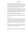
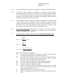
8.2.2.3.
The production of a series shall be deemed to conform or not to conform on the
basis of a sampling test of the vehicles once a pass decision is reached for all the
pollutants or a fail decision is reached for one pollutant, according to the test
criteria applied in the appropriate appendix.
When a pass decision has been reached for one pollutant, that decision shall not
be changed by any additional tests carried out to reach a decision for the other
pollutants.
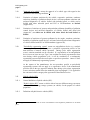
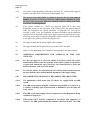
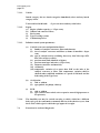
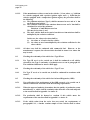
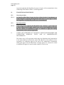
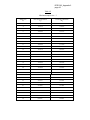
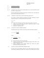
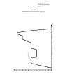
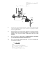
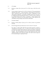
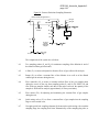
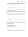
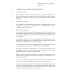
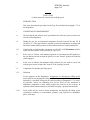
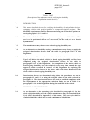
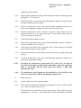
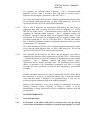
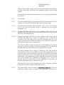
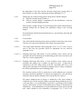
If no pass decision is reached for all the pollutants and no fail decision is
reached for one pollutant, a test shall be carried out on another vehicle (see
Figure 2).
ECE.R.83/06_main
page 31
Figure 2
8.2.3.
Notwithstanding the requirements of paragraph 5.3.1. of this Regulation, the
tests shall be carried out on vehicles coming straight off the production line.
8.2.3.1.
However, at the request of the manufacturer, the tests may be carried out on
vehicles which have completed:
(a) A maximum of 3,000 km for vehicles equipped with a positive ignition
engine;
(b) A maximum of 15,000 km for vehicles equipped with a compression
ignition engine.
The running-in procedure shall be conducted by the manufacturer, who shall
undertake not to make any adjustments to these vehicles.
ECE.R.83/06_main
page 32
8.2.3.2.
If the manufacturer wishes to run in the vehicles, ('x' km, where x ≤ 3,000 km
for vehicles equipped with a positive ignition engine and x ≤ 15,000 km for
vehicles equipped with a compression ignition engine), the procedure shall be
the following:
(a) The pollutant emissions (Type I) shall be measured at zero and at 'x' km
on the first tested vehicle;
(b) The evolution coefficient of the emissions between zero and 'x' km shall be
calculated for each of the pollutant:
Emissions 'x' km/Emissions zero km
This may be less than 1; and
(c) The other vehicles shall not be run in, but their zero km emissions shall be
multiplied by the evolution coefficient.
In this case, the values to be taken shall be:
(i) the values at 'x' km for the first vehicle;
(ii) the values at zero km multiplied by the evolution coefficient for the
other vehicles.
8.2.3.3.
All these tests shall be conducted with commercial fuel. However, at the
manufacturer's request, the reference fuels described in Annex 10 or Annex 10a
may be used.
8.3.
Checking the conformity of the vehicle for a Type III test
8.3.1.
If a Type III test is to be carried out, it shall be conducted on all vehicles
selected for the Type I conformity of production test set out in paragraph 8.2.
The conditions laid down in Annex 6 shall apply.
8.4.
Checking the conformity of the vehicle for a Type IV test
8.4.1.
If a Type IV test is to be carried out, it shall be conducted in accordance with
Annex 7.
8.5.
Checking the conformity of the vehicle for On-board Diagnostics (OBD)
8.5.1.
If a verification of the performance of the OBD system is to be carried out, it
shall be conducted in accordance with the following requirements:
8.5.1.1.
When the approval authority determines that the quality of production seems
unsatisfactory, a vehicle shall be randomly taken from the series and subjected
to the tests described in Appendix 1 to Annex 11.
8.5.1.2.
The production shall be deemed to conform if this vehicle meets the
requirements of the tests described in Appendix 1 to Annex 11.
8.5.1.3.
If the vehicle taken from the series does not satisfy the requirements of
paragraph 8.5.1.1., a further random sample of four vehicles shall be taken
ECE.R.83/06_main
page 33
from the series and subjected to the tests described in Appendix 1 to Annex 11.
The tests may be carried out on vehicles which have been run in for no more
than 15,000 km.
8.5.1.4.
The production shall be deemed to conform if at least 3 vehicles meet the
requirements of the tests described in Annex 11, Appendix 1.
8.6.
Checking the conformity of a vehicle fuelled by LPG or NG/biomethane
8.6.1.
Tests for conformity of production may be performed with a commercial fuel of
which the C3/C4 ratio lies between those of the reference fuels in the case of
LPG, or of which the Wobbe index lies between those of the extreme reference
fuels in the case of NG/biomethane. In that case a fuel analysis shall be
presented to the approval authority.
9.
IN-SERVICE CONFORMITY
9.1.
Introduction
This paragraph sets out the in-service conformity requirements for vehicles type
approved to this Regulation.
9.2.
Audit of in-service conformity
9.2.1.
The audit of in-service conformity by the approval authority shall be conducted
on the basis of any relevant information that the manufacturer has, under the
same procedures as those for the conformity of production defined in
Appendix 2 to Agreement E/ECE/324//E/ECE/TRANS/505/Rev.2. Information
from approval authority and Contracting Party surveillance testing may
complement the in-service monitoring reports supplied by the manufacturer.
9.2.2.
The figures 4/1 and 4/2 of Appendix 4 to this Regulation illustrate the procedure
for in-service conformity checking. The process for in-service conformity is
described in Appendix 5 to this Regulation.
9.2.3.
As part of the information provided for the in-service conformity control, at the
request of the approval authority, the manufacturer shall report to the type
approval authority on warranty claims, warranty repair works and OBD faults
recorded at servicing, according to a format agreed at type approval. The
information shall detail the frequency and substance of faults for emissions
related components and systems. The reports shall be filed at least once a year
for each vehicle model for the duration of the period of up to 5 years of age
or 100,000 km, whichever is the sooner.
9.2.4.
Parameters defining the in-service family
The in-service family may be defined by basic design parameters which shall be
common to vehicles within the family. Accordingly, vehicle types may be
ECE.R.83/06_main
page 34
considered as belonging to the same in-service family if they have in common, or
within the stated tolerances, the following parameters:
9.2.4.1.
Combustion process (two stroke, four stroke, rotary);
9.2.4.2.
Number of cylinders;
9.2.4.3.
Configuration of the cylinder block (in-line, V, radial, horizontally opposed,
other). The inclination or orientation of the cylinders is not a criteria);
9.2.4.4.
Method of engine fuelling (e.g. indirect or direct injection);
9.2.4.5.
Type of cooling system (air, water, oil);
9.2.4.6.
Method of aspiration (naturally aspirated, pressure charged);
9.2.4.7.
Fuel for which the engine is designed (petrol, diesel, NG/biomethane, LPG, etc.).
Bi-fuelled vehicles may be grouped with dedicated fuel vehicles providing one of
the fuels is common;
9.2.4.8.
Type of catalytic converter (three-way catalyst, lean NOX trap, SCR, lean NOX
catalyst or other(s));
9.2.4.9.
Type of particulate trap (with or without);
9.2.4.10.
Exhaust gas recirculation (with or without, cooled or non cooled); and
9.2.4.11.
Engine cylinder capacity of the largest engine within the family minus 30 per
cent.
9.2.5.
Information requirements
An audit of in-service conformity will be conducted by the approval authority
on the basis of information supplied by the manufacturer. Such information
shall include in particular, the following:
9.2.5.1.
The name and address of the manufacturer;
9.2.5.2.
The name, address, telephone and fax numbers and e-mail address of the
authorised representative within the areas covered by the manufacturer's
information;
9.2.5.3.
The model name(s) of the vehicles included in the manufacturer's information;
9.2.5.4.
Where appropriate, the list of vehicle types covered within the manufacturer's
information, i.e. the in-service family group in accordance with
paragraph 9.2.1.;
ECE.R.83/06_main
page 35
9.2.5.5.
The vehicle identification number (VIN) codes applicable to these vehicle types
within the in-service family (VIN prefix);
9.2.5.6.
The numbers of the type approvals applicable to these vehicle types within the
in-service family, including, where applicable, the numbers of all extensions and
field fixes/recalls (re-works);
9.2.5.7.
Details of extensions, field fixes/recalls to those type approvals for the vehicles
covered within the manufacturer's information (if requested by the approval
authority);
9.2.5.8.
The period of time over which the manufacturer's information was collected;
9.2.5.9.
The vehicle build period covered within the manufacturer's information (e.g.
vehicles manufactured during the 2007 calendar year);
9.2.5.10.
The manufacturer's in-service conformity checking procedure, including:
(a) Vehicle location method;
(b) Vehicle selection and rejection criteria;
(c) Test types and procedures used for the programme;
(d) The manufacturer's acceptance/rejection criteria for the in-service family
group;
(e) Geographical area(s) within which the manufacturer has collected
information;
(f) Sample size and sampling plan used.
9.2.5.11.
The results from the manufacturer's in-service conformity procedure,
including:
(a) Identification of the vehicles included in the programme (whether tested
or not). The identification shall include the following:
(i) model name,
(ii) vehicle identification number (VIN),
(iii) vehicle registration number,
(iv) date of manufacture,
(v) region of use (where known),
(vi) tyres fitted.
(b) The reason(s) for rejecting a vehicle from the sample;
(c) Service history for each vehicle in the sample (including any re-works);
(d) Repair history for each vehicle in the sample (where known);
(e) Test data, including the following:
(i) date of test,
(ii) location of test,
(iii) distance indicated on vehicle odometer,
(iv) test fuel specifications (e.g. test reference fuel or market fuel),
(v) test conditions (temperature, humidity, dynamometer inertia
weight),
(vi) dynamometer settings (e.g. power setting),
(vii) test results (from at least three different vehicles per family).
ECE.R.83/06_main
page 36
9.2.5.12.
Records of indication from the OBD system.
9.3.
Selection of vehicles for in-service conformity
9.3.1.
The information gathered by the manufacturer shall be sufficiently
comprehensive to ensure that in-service performance can be assessed for
normal conditions of use as defined in paragraph 9.2. The manufacturer's
sampling shall be drawn from at least two Contracting Parties with
substantially different vehicle operating conditions. Factors such as differences
in fuels, ambient conditions, average road speeds, and urban/highway driving
split shall be taken into consideration in the selection of the Contracting Parties.
9.3.2.
In selecting the Contracting Parties for sampling vehicles, the manufacturer
may select vehicles from a Contracting Party that is considered to be
particularly representative. In this case, the manufacturer shall demonstrate to
the approval authority which granted the type approval that the selection is
representative (e.g. by the market having the largest annual sales of a vehicle
family within the applicable Contracting Party). When an in-service family
requires more than one sample lot to be tested as defined in paragraph 9.3.5.,
the vehicles in the second and third sample lots shall reflect different vehicle
operating conditions from those selected for the first sample.
9.3.3.
The emissions testing may be done at a test facility which is located in a
different market or region from where the vehicles have been selected.
9.3.4.
The in-service conformity tests by the manufacturer shall be continuously
carried out reflecting the production cycle of applicable vehicles types within a
given in-service vehicle family.
The maximum time period between
commencing two in-service conformity checks shall not exceed 18 months. In
the case of vehicle types covered by an extension to the type approval that did
not require an emissions test, this period may be extended up to 24 months.
9.3.5.
When applying the statistical procedure defined in Appendix 4, the number of
sample lots shall depend on the annual sales volume of an in-service family in
the territories of a regional organization (e.g. European Community), as defined
in the following table:
Registrations per calendar year
Up to 100,000
100,001 to 200,000
Above 200,000
9.4.
Number of sample lots
1
2
3
On the basis of the audit referred to in paragraph 9.2., the approval authority
shall adopt one of the following decisions and actions:
(a) Decide that the in-service conformity of a vehicle type or a vehicle inservice family is satisfactory and not take any further action;
ECE.R.83/06_main
page 37
(b)
(c)
(d)
Decide that the data provided by the manufacturer is insufficient to reach
a decision and request additional information or test data from the
manufacturer;
Decide that based on data from the approval authority or Contracting
Party surveillance testing programmes, that information provided by the
manufacturer is insufficient to reach a decision and request additional
information or test data from the manufacturer;
Decide that the in-service conformity of a vehicle type, that is part of an
in-service family, is unsatisfactory and proceed to have such vehicle type
tested in accordance with Appendix 3.
9.4.1.
Where Type I tests are considered necessary to check the conformity of
emission control devices with the requirements for their performance while in
service, such tests shall be carried out using a test procedure meeting the
statistical criteria defined in Appendix 2.
9.4.2.
The approval authority, in cooperation with the manufacturer, shall select a
sample of vehicles with sufficient mileage whose use under normal conditions
can be reasonably assured. The manufacturer shall be consulted on the choice
of the vehicles in the sample and allowed to attend the confirmatory checks of
the vehicles.
9.4.3.
The manufacturer shall be authorised, under the supervision of the approval
authority, to carry out checks, even of a destructive nature, on those vehicles
with emission levels in excess of the limit values with a view to establishing
possible causes of deterioration which cannot be attributed to the manufacturer
(e.g. use of leaded petrol before the test date). Where the results of the checks
confirm such causes, those test results shall be excluded from the conformity
check.
10.
PENALTIES FOR NON-CONFORMITY OF PRODUCTION
10.1.
The approval granted in respect of a vehicle type pursuant to this amendment, may
be withdrawn if the requirements laid down in paragraph 8.1. above are not complied
with or if the vehicle or vehicles taken fail to pass the tests prescribed in
paragraph 8.1.1. above.
10.2.
If a Contracting Party which applies this Regulation withdraws an approval it has
previously granted, it shall forthwith so notify the other Contracting Parties applying
this Regulation, by means of a communication form conforming to the model in
Annex 2 to this Regulation.
11.
PRODUCTION DEFINITELY DISCONTINUED
If the holder of the approval completely ceases to manufacture a type of vehicle
approved in accordance with this Regulation, he shall so inform the type approval
authority which granted the approval. Upon receiving the relevant communication,
that authority shall inform thereof the other Contracting Parties to the 1958
ECE.R.83/06_main
page 38
Agreement applying this Regulation by means of copies of the communication form
conforming to the model in Annex 2 to this Regulation.
12.
TRANSITIONAL PROVISIONS
12.1.
General provisions
12.1.1.
As from the official date of entry into force of the 06 series of amendments, no
Contracting Party applying this Regulation shall refuse to grant approval under
this Regulation as amended by the 06 series of amendments.
12.2.
Special provisions
12.2.1.
Contracting Parties applying this Regulation may continue to grant approvals
to those vehicles which comply with previous levels of this Regulation, provided
that the vehicles are intended for export to countries to apply the relating
requirements in their national legislations.
13.
NAMES AND ADDRESSES OF TECHNICAL SERVICES RESPONSIBLE FOR
CONDUCTING APPROVAL TESTS, AND OF ADMINISTRATIVE
DEPARTMENTS
The Parties to the 1958 Agreement which apply this Regulation shall communicate
to the United Nations Secretariat the names and addresses of the technical services
responsible for conducting approval tests and of the administrative departments
which grant approval and to which forms certifying approval or extension or refusal
or withdrawal of approval, issued in other countries, are to be sent.
ECE R.83_Appendix 1
page 39
Appendix 1
PROCEDURE FOR VERIFYING THE CONFORMITY OF PRODUCTION
REQUIREMENTS IF THE PRODUCTION STANDARD DEVIATION GIVEN BY THE
MANUFACTURER IS SATISFACTORY
1.
This appendix describes the procedure to be used to verify the production conformity for
the Type I test when the manufacturer's production standard deviation is satisfactory.
2.
With a minimum sample size of 3, the sampling procedure is set so that the probability of a
lot passing a test with 40 per cent of the production defective is 0.95 (producer's risk
= 5 per cent) while the probability of a lot being accepted with 65 per cent of the
production defective is 0.l (consumer's risk = 10 per cent).
3.
For each of the pollutants given in Table 1 of paragraph 5.3.1.4. of this Regulation, the
following procedure is used (see Figure 2 of this Regulation).
Taking:
L = the natural logarithm of the limit value for the pollutant,
xi = the natural logarithm of the measurement for the i-th vehicle of the sample,
4.
s=
an estimate of the production standard deviation (after taking the natural logarithm of
the measurements),
n=
the current sample number.
Compute for the sample the test statistic quantifying the sum of the standard deviations
from the limit and defined as:
1 n
∑ ( L −xi )
s i =1
5.
Then:
5.1. If the test statistic is greater than the pass decision number for the sample size given in
Table 1/1 below, the pollutant is passed,
5.2. If the test statistic is less than the fail decision number for the sample size given in Table
1/1 below, the pollutant is failed; otherwise, an additional vehicle is tested and the
calculation reapplied to the sample with a sample size one unit greater.
ECE R.83_Appendix 1
page 40
Table 1/1
Cumulative number
of tested vehicles (current sample size)
Pass decision threshold
Fail decision threshold
3
3.327
-4.724
4
3.261
-4.79
5
3.195
-4.856
6
3.129
-4.922
7
3.063
-4.988
8
2.997
-5.054
9
2.931
-5.12
10
2.865
-5.185
11
2.799
-5.251
12
2.733
-5.317
13
2.667
-5.383
14
2.601
-5.449
15
2.535
-5.515
16
2.469
-5.581
17
2.403
-5.647
18
2.337
-5.713
19
2.271
-5.779
20
2.205
-5.845
21
2.139
-5.911
22
2.073
-5.977
23
2.007
-6.043
24
1.941
-6.109
25
1.875
-6.175
26
1.809
-6.241
27
1.743
-6.307
28
1.677
-6.373
29
1.611
-6.439
30
1.545
-6.505
31
1.479
-6.571
32
-2.112
-2.112
ECE R.83_Appendix 2
page 41
Appendix 2
PROCEDURE
FOR
VERIFYING
THE
CONFORMITY
OF
PRODUCTION
REQUIREMENTS
IF THE PRODUCTION STANDARD DEVIATION GIVEN BY THE MANUFACTURER
IS EITHER NOT SATISFACTORY OR NOT AVAILABLE
1.
This appendix describes the procedure to be used to verify the production conformity
requirements for the Type I test when the manufacturer's evidence of production standard
deviation is either not satisfactory or not available.
2.
With a minimum sample size of 3, the sampling procedure is set so that the probability of a
lot passing a test with 40 per cent of the production defective is 0.95 (producer's risk
= 5 per cent) while the probability of a lot being accepted with 65 per cent of the
production defective is 0.l (consumer's risk = 10 per cent).
3.
The measurements of the pollutants given in Table 1 of paragraph 5.3.1.4. of this
Regulation are considered to be log normally distributed and shall first be transformed by
taking their natural logarithms. Let m0 and m denote the minimum and maximum sample
sizes respectively (m0 = 3 and m = 32) and let n denote the current sample number.
4.
If the natural logarithms of the measurements in the series are x1,x2 ..., xi and L is the
natural logarithm of the limit value for the pollutant, then define:
d1 = x1 – L
dn =
1 n
∑ di
n i =1
and
Vn2 =
5.
(
1 n
∑ di − d n
n i =1
)
2
Table 1/2 shows values of the pass (An) and fail (Bn) decision numbers against current
sample number. The test statistic is the ratio d n/Vn and shall be used to determine whether
the series has passed or failed as follows:
For mo ≤ n ≤ m
(i)
Pass the series if
dn
≤ An
Vn
(ii)
Fail the series if
dn
≥ Bn
Vn
ECE R.83_Appendix 2
page 42
(iii) Take another measurement if
6.
An < Vdnn < Bn
Remarks
The following recursive formulae are useful for computing successive values of the test
statistic:
ECE R.83_Appendix 2
page 43
Table 1/2
Minimum sample size = 3
Sample size
(n)
Pass decision threshold
(An)
Fail decision threshold
(Bn)
3
-0.80381
16.64743
4
-0.76339
7.68627
5
-0.72982
4.67136
6
-0.69962
3.25573
7
-0.67129
2.45431
8
-0.64406
1.94369
9
-0.61750
1.59105
10
-0.59135
1.33295
11
-0.56542
1.13566
12
-0.53960
0.97970
13
-0.51379
0.85307
14
-0.48791
0.74801
15
-0.46191
0.65928
16
-0.43573
0.58321
17
-0.40933
0.51718
18
-0.38266
0.45922
19
-0.35570
0.40788
20
-0.32840
0.36203
21
-0.30072
0.32078
22
-0.27263
0.28343
23
-0.24410
0.24943
24
-0.21509
0.21831
25
-0.18557
0.18970
26
-0.15550
0.16328
27
-0.12483
0.13880
28
-0.09354
0.11603
29
-0.06159
0.09480
30
-0.02892
0.07493
31
0.00449
0.05629
32
0.03876
0.03876
ECE R.83_Appendix 3
page 44
Appendix 3
IN-SERVICE CONFORMITY CHECK
1.
INTRODUCTION
This appendix sets out the criteria referred to in paragraph 8.2.7. of this Regulation
regarding the selection of vehicles for testing and the procedures for the in-service
conformity control.
2.
SELECTION CRITERIA
The criteria for acceptance of a selected vehicle are defined in paragraphs 2.1. to 2.8. of
this appendix. Information is collected by vehicle examination and an interview with
the owner/driver.
2.1.
The vehicle shall belong to a vehicle type that is type approved under this Regulation
and covered by a certificate of conformity in accordance with the 1958 Agreement. It
shall be registered and used in a country of the Contracting Parties.
2.2.
The vehicle shall have been in service for at least 15,000 km or 6 months, whichever is
the later, and for no more than 100,000 km or 5 years, whichever is the sooner.
2.3.
There shall be a maintenance record to show that the vehicle has been properly
maintained, e.g. has been serviced in accordance with the manufacturer's
recommendations.
2.4.
The vehicle shall exhibit no indications of abuse (e.g. racing, overloading, misfuelling,
or other misuse), or other factors (e.g. tampering) that could affect emission
performance. In the case of vehicles fitted with an OBD system, the fault code and
mileage information stored in the computer is taken into account. A vehicle shall not be
selected for testing if the information stored in the computer shows that the vehicle has
operated after a fault code was stored and a relatively prompt repair was not carried out.
2.5.
There shall have been no unauthorised major repair to the engine or major repair of the
vehicle.
2.6.
The lead content and sulphur content of a fuel sample from the vehicle tank shall meet
applicable standards and there shall be no evidence of misfuelling. Checks may be done
in the exhaust, etc.
2.7.
There shall be no indication of any problem that might jeopardise the safety of
laboratory personnel.
2.8.
All anti-pollution system components on the vehicle shall be in conformity with the
applicable type approval.
ECE R.83_Appendix 3
page 45
3.
DIAGNOSIS AND MAINTENANCE
Diagnosis and any normal maintenance necessary shall be performed on vehicles
accepted for testing, prior to measuring exhaust emissions, in accordance with the
procedure laid down in paragraphs 3.1. to 3.7. below.
3.1.
The following checks shall be carried out: checks on air filter, all drive belts, all fluid
levels, radiator cap, all vacuum hoses and electrical wiring related to the anti-pollution
system for integrity; checks on ignition, fuel metering and anti-pollution device
components for maladjustments and/or tampering. All discrepancies shall be recorded.
3.2.
The OBD system shall be checked for proper functioning. Any malfunction indications
in the OBD memory shall be recorded and the requisite repairs shall be carried out. If
the OBD malfunction indicator registers a malfunction during a preconditioning cycle,
the fault may be identified and repaired. The test may be re-run and the results of that
repaired vehicle used.
3.3.
The ignition system shall be checked and defective components replaced, for example
spark plugs, cables, etc.
3.4.
The compression shall be checked. If the result is unsatisfactory the vehicle is rejected.
3.5.
The engine parameters shall be checked to the manufacturer's specifications and
adjusted if necessary.
3.6.
If the vehicle is within 800 km of a scheduled maintenance service, that service shall be
performed according to the manufacturer's instructions. Regardless of odometer
reading, the oil and air filter may be changed at the request of the manufacturer.
3.7.
Upon acceptance of the vehicle, the fuel shall be replaced with appropriate emission test
reference fuel, unless the manufacturer accepts the use of market fuel.
3.8.
In the case of vehicles equipped with periodically regenerating systems as defined in
paragraph 2.20., it shall be established that the vehicle is not approaching a regeneration
period. (The manufacturer shall be given the opportunity to confirm this).
3.8.1.
If this is the case, the vehicle shall be driven until the end of the regeneration. If
regeneration occurs during emissions measurement, then a further test shall be carried
out to ensure that regeneration has been completed. A complete new test shall then be
performed, and the first and second test results not taken into account.
3.8.2.
As an alternative to paragraph 3.8.1., if the vehicle is approaching a regeneration the
manufacturer may request that a specific conditioning cycle is used to ensure that
regeneration (e.g. this may involve high speed, high load driving).
The manufacturer may request that testing may be carried out immediately after
regeneration or after the conditioning cycle specified by the manufacturer and normal
test preconditioning.
ECE R.83_Appendix 3
page 46
4.
IN-SERVICE TESTING
4.1.
When a check on vehicles is deemed necessary, emission tests in accordance with
Annex 4a to this Regulation are performed on pre-conditioned vehicles selected in
accordance with the requirements of paragraphs 2. and 3. of this appendix. Preconditioning cycles additional to those specified in Section 6.3. of Annex 4a to this
Regulation will only be allowed if they are representative of normal driving.
4.2.
Vehicles equipped with an OBD system may be checked for proper in-service
functionality of the malfunction indication, etc., in relation to levels of emissions (e.g.
the malfunction indication limits defined in Annex 11 to this Regulation) for the type
approved specifications.
4.3.
The OBD system may be checked, for example, for levels of emissions above the
applicable limit values with no malfunction indication, systematic erroneous activation
of the malfunction indication and identified faulty or deteriorated components in the
OBD system.
4.4.
If a component or system operates in a manner not covered by the particulars in the type
approval certificate and/or information package for such vehicle types and such
deviation has not been authorised under the 1958 Agreement, with no malfunction
indication by the OBD, the component or system shall not be replaced prior to emission
testing, unless it is determined that the component or system has been tampered with or
abused in such a manner that the OBD does not detect the resulting malfunction.
5.
EVALUATION OF RESULTS
5.1.
The test results are submitted to the evaluation procedure in accordance with
Appendix 4.
5.2.
Test results shall not be multiplied by deterioration factors.
5.3.
In the case of periodically regenerating systems as defined in paragraph 2.20., the
results shall be multiplied by the factors Ki obtained at the time when type approval was
granted.
6.
PLAN OF REMEDIAL MEASURES
6.1.
When more than one vehicle is found to be an outlying emitter that either,
(a) meets the conditions of paragraph 3.2.3. of Appendix 4 and where both the
approval authority and the manufacturer agree that the excess emission is due to
the same cause, or
(b) meets the conditions of paragraph 3.2.4. of Appendix 4 where the approval
authority has determined that the excess emission is due to the same cause,
the approval authority shall request the manufacturer to submit a plan of remedial
measures to remedy the non-compliance.
ECE R.83_Appendix 3
page 47
6.2.
The plan of remedial measures shall be filed with the type approval authority not later
than 60 working days from the date of the notification referred to in paragraph 6.1.
above. The type approval authority shall within 30 working days declare its approval or
disapproval of the plan of remedial measures. However, where the manufacturer can
demonstrate, to the satisfaction of the competent type approval authority, that further
time is required to investigate the non-compliance in order to submit a plan of remedial
measures, an extension is granted.
6.3.
The remedial measures shall apply to all vehicles likely to be affected by the same
defect. The need to amend the type approval documents shall be assessed.
6.4.
The manufacturer shall provide a copy of all communications related to the plan of
remedial measures, and shall also maintain a record of the recall campaign, and supply
regular status reports to the type approval authority.
6.5.
The plan of remedial measures shall include the requirements specified in
paragraphs 6.5.1. to 6.5.11. The manufacturer shall assign a unique identifying name or
number to the plan of remedial measures.
6.5.1.
A description of each vehicle type included in the plan of remedial measures.
6.5.2.
A description of the specific modifications, alterations, repairs, corrections,
adjustments, or other changes to be made to bring the vehicles into conformity
including a brief summary of the data and technical studies which support the
manufacturer's decision as to the particular measures to be taken to correct the nonconformity.
6.5.3.
A description of the method by which the manufacturer informs the vehicle owners.
6.5.4.
A description of the proper maintenance or use, if any, which the manufacturer
stipulates as a condition of eligibility for repair under the plan of remedial measures,
and an explanation of the manufacturer's reasons for imposing any such condition. No
maintenance or use conditions may be imposed unless it is demonstrably related to the
non-conformity and the remedial measures.
6.5.5.
A description of the procedure to be followed by vehicle owners to obtain correction of
the non-conformity. This shall include a date after which the remedial measures may be
taken, the estimated time for the workshop to perform the repairs and where they can be
done. The repair shall be done expediently, within a reasonable time after delivery of
the vehicle.
6.5.6.
A copy of the information transmitted to the vehicle owner.
6.5.7.
A brief description of the system which the manufacturer uses to assure an adequate
supply of component or systems for fulfilling the remedial action. It shall be indicated
when there will be an adequate supply of components or systems to initiate the
campaign.
ECE R.83_Appendix 3
page 48
6.5.8.
A copy of all instructions to be sent to those persons who are to perform the repair.
6.5.9.
A description of the impact of the proposed remedial measures on the emissions, fuel
consumption, derivability, and safety of each vehicle type, covered by the plan of
remedial measures with data, technical studies, etc. which support these conclusions.
6.5.10. Any other information, reports or data the type approval authority may reasonably
determine is necessary to evaluate the plan of remedial measures.
6.5.11. Where the plan of remedial measures includes a recall, a description of the method for
recording the repair shall be submitted to the type approval authority. If a label is used,
an example of it shall be submitted.
6.6.
The manufacturer may be required to conduct reasonably designed and necessary tests
on components and vehicles incorporating a proposed change, repair, or modification to
demonstrate the effectiveness of the change, repair, or modification.
6.7.
The manufacturer is responsible for keeping a record of every vehicle recalled and
repaired and the workshop which performed the repair. The type approval authority
shall have access to the record on request for a period of 5 years from the
implementation of the plan of remedial measures.
6.8.
The repair and/or modification or addition of new equipment shall be recorded in a
certificate supplied by the manufacturer to the vehicle owner.
ECE R.83_Appendix 4
page 49
Appendix 4
STATISTICAL PROCEDURE FOR IN-SERVICE CONFORMITY TESTING
1.
This appendix describes the procedure to be used to verify the in-service conformity
requirements for the Type I test.
2.
Two different procedures are to be followed:
(i) One dealing with vehicles identified in the sample, due to an emission-related
defect, causing outliers in the results (paragraph 3. below).
(ii) The other deals with the total sample (paragraph 4. below).
3.
PROCEDURE TO BE FOLLOWED WITH OUTLYING EMITTERS IN THE
SAMPLE
3.1.
With a minimum sample size of three and a maximum sample size as determined by
the procedure of paragraph 4., a vehicle is taken at random from the sample and the
emissions of the regulated pollutants are measured to determine if it is an outlying
emitter.
3.2.
A vehicle is said to be an outlying emitter when the conditions given in
paragraph 3.2.1. are met.
3.2.1.
In the case of a vehicle that has been type approved according to the limit values
given in Table 1 in paragraph 5.3.1.4., an outlying emitter is a vehicle where the
applicable limit value for any regulated pollutant is exceeded by a factor of 1.5.
3.2.3.
In the specific case of a vehicle with a measured emission for any regulated pollutant
within the 'intermediate zone' 1/.
3.2.3.1.
If the vehicle meets the conditions of this paragraph, the cause of the excess emission
shall be determined and another vehicle is then taken at random from the sample.
3.2.3.2.
Where more than one vehicle meets the condition of this paragraph, the
administrative department and the manufacturer shall determine if the excess
emission from both vehicles is due to the same cause or not.
3.2.3.2.1. If the administrative department and the manufacturer both agree that the excess
emission is due to the same cause, the sample is regarded as having failed and the
plan of remedial measures outlined in paragraph 6. of Appendix 3 applies.
3.2.3.2.2. If the administrative department and the manufacturer can not agree on either the
cause of the excess emission from an individual vehicle or whether the causes for
1
/
For any vehicle, the "intermediate zone" is determined as follows: The vehicle shall meet the conditions
given in either paragraph 3.2.1. or paragraph 3.2.2. and, in addition, the measured value for the same regulated
pollutant shall be below a level that is determined from the product of the limit value for the same regulated
pollutant given in Table 1 in paragraph 5.3.1.4. multiplied by a factor of 2.5.
ECE R.83_Appendix 4
page 50
more than one vehicle are the same, another vehicle is taken at random from the
sample, unless the maximum sample size has already been reached.
3.2.3.3.
When only one vehicle meeting the conditions of this paragraph has been found, or
when more than one vehicle has been found and the administrative department and
the manufacturer agree it is due to different causes, another vehicle is taken at
random from the sample, unless the maximum sample size has already been reached.
3.2.3.4.
If the maximum sample size is reached and not more than one vehicle meeting the
requirements of this paragraph has been found where the excess emission is due to
the same cause, the sample is regarded as having passed with regard to the
requirements of paragraph 3. of this appendix.
3.2.3.5.
If, at any time, the initial sample has been exhausted, another vehicle is added to the
initial sample and that vehicle is taken.
3.2.3.6.
Whenever another vehicle is taken from the sample, the statistical procedure of
paragraph 4. of this appendix is applied to the increased sample.
3.2.4.
In the specific case of a vehicle with a measured emission for any regulated pollutant
within the "failure zone"; 2/
3.2.4.1.
If the vehicle meets the conditions of this paragraph, the administrative department
shall determine the cause of the excess emission and another vehicle is then taken at
random from the sample.
3.2.4.2.
Where more than one vehicle meets the condition of this paragraph, and the
administrative department determines that the excess emission is due to the same
cause, the manufacturer shall be informed that the sample is regarded as having
failed, together with the reasons for that decision, and the plan of remedial measures
outlined in paragraph 6. of Appendix 3 applies.
3.2.4.3.
When only one vehicle meeting the conditions of this paragraph has been found, or
when more than one vehicle has been found and the administrative department has
determined that it is due to different causes, another vehicle is taken at random from
the sample, unless the maximum sample size has already been reached.
3.2.4.4.
If the maximum sample size is reached and not more than one vehicle meeting the
requirements of this paragraph has been found where the excess emission is due to
the same cause, the sample is regarded as having passed with regard to the
requirements of paragraph 3. of this appendix.
3.2.4.5.
If, at any time, the initial sample has been exhausted, another vehicle is added to the
initial sample and that vehicle is taken.
2
/
For any vehicle, the "failure zone" is determined as follows. The measured value for any regulated
pollutant exceeds a level that is determined from the product of the limit value for the same regulated pollutant
given in Table 1 in paragraph 5.3.1.4. multiplied by a factor of 2.5.
ECE R.83_Appendix 4
page 51
3.2.4.6.
Whenever another vehicle is taken from the sample, the statistical procedure of
paragraph 4. of this appendix is applied to the increased sample.
3.2.5.
Whenever a vehicle is not found to be an outlying emitter, another vehicle is taken at
random from the sample.
3.3.
When an outlying emitter is found, the cause of the excess emission shall be
determined.
3.4.
When more than one vehicle is found to be an outlying emitter, due to the same
cause, the sample is regarded as having failed."
3.5.
When only one outlying emitter has been found, or when more than one outlying
emitter is found, but due to different causes, the sample is increased by one vehicle,
unless the maximum sample size has already been reached.
3.5.1.
When in the increased sample more than one vehicle is found to be an outlying
emitter, due to the same cause, the sample is regarded as having failed.
3.5.2.
When in the maximum sample size not more than one outlying emitter is found,
where the excess emission is due to the same cause, the sample is regarded as having
passed with regard to the requirements of paragraph 3. of this appendix.
3.6.
Whenever a sample is increased due to the requirements of paragraph 3.5., the
statistical procedure of paragraph 4. below is applied to the increased sample.
4.
PROCEDURE TO BE FOLLOWED WITHOUT SEPARATE EVALUATION OF
OUTLYING EMITTERS IN THE SAMPLE
4.1.
With a minimum sample size of three the sampling procedure is set so that the
probability of a batch passing a test with 40 per cent of the production defective
is 0.95 (producer's risk = 5 per cent) while the probability of a batch being accepted
with 75 per cent of the production defective is 0.15 (consumer's risk = 15 per cent).
4.2.
For each of the pollutants given in the Table 1 of paragraph 5.3.1.4. of this
Regulation, the following procedure is used (see Figure 4/2 below).
where:
L = the limit value for the pollutant,
xi = the value of the measurement for the i-th vehicle of the sample,
n = the current sample number.
4.3.
The test statistic quantifying the number of non-conforming vehicles, i.e. xi > L, is
computed for the sample.
4.4.
Then:
(i) If the test statistic does not exceed the pass decision number for the sample size
given in the following table, a pass decision is reached for the pollutant,
ECE R.83_Appendix 4
page 52
(ii)
If the test statistic equals or exceeds the fail decision number for the sample
size given in the following table, a fail decision is reached for the pollutant,
(iii) Otherwise, an additional vehicle is tested and the procedure is applied to the
sample with one extra unit.
In the following table the pass and fail decision numbers are computed in accordance
with the International Standard ISO 8422:1991.
5
A sample is regarded as having passed the test when it has passed both the
requirements of paragraphs 3. and 4. of this appendix.
Table 4/1
TABLE FOR ACCEPTANCE/REJECTION SAMPLING PLAN BY ATTRIBUTES
Cumulative sample size (n)
Pass decision number
Fail decision number
3
4
5
6
7
8
9
10
11
12
13
14
15
16
17
18
19
20
0
1
1
2
2
3
4
4
5
5
6
6
7
8
8
9
9
11
5
6
6
7
8
8
9
9
10
11
11
12
12
13
13
12
ECE R.83_Appendix 4
page 53
Figure 4/1
In-service conformity checking - audit procedure
START
Vehicle manufacturer and type approval authority
complete vehicle approval for the new vehicle type.
Type approval authority (TAA) grants type approval
Manufacture and sales of approved vehicle type
Vehicle manufacturer develops own in-service
conformity procedure
Vehicle manufacturer carries out own in-service
conformity procedure (vehicle type or family)
In-house inservice
conformity report
for approved
vehicle type or
family
Vehicle manufacturer compiles report of the inhouse procedure (including all data required by
paregraph 8.2.1.)
Information from approval authority
TAA (1) reviews manufacturer's in-service
conformity report and complementary
information from type approval authority
Does the TAA (1)
accept that
manufacturer's in-service
conformity report
confirms acceptability of
a vehicle type within the
family? (paragraph
8.2.1.)
YES
Process Completed
No further action required
Manufacturer submits inservice conformity report
to TAA (1) for audit
NO
Does TAA (1)
decide that
information is
insufficient to
reach a decision?
Manufacturer
provides or
obtains
additional
information or
test data
YES
Manufacturer
compiles new
in-service
conformity
report
NO
TAA (1) begins formal in-service
compliance surveillance
programme on suspect vehicle
type (as described in Appendix 3)
Go to Figure
4/2 of
Appendix 4
ECE R.83_Appendix 4
page 54
Figure 4/2
In-service conformity testing - selection and test of vehicle
NO, or UNCERTAIN
ECE R.83_Appendix 5
page 55
Appendix 5
RESPONSIBILITIES FOR IN-SERVICE CONFORMITY
1.
The process of checking in-service conformity is illustrated in Figure 1
2.
The manufacturer shall compile all the information needed to comply with the
requirements of this annex. The approval authority may also take information from
surveillance programmes into consideration.
3.
The approval authority shall conduct all the procedures and tests necessary to ensure
that the requirements regarding the in-service conformity are met (Phases 2 to 4).
4.
In the event of discrepancies or disagreements in the assessment of information
supplied, the approval authority shall request clarification from the technical service
that conducted the type approval test.
5.
The manufacturer shall establish and implement a plan of remedial measures. This
plan shall be approved by the approval authority before it is implemented (Phase 5).
Figure 1: Illustration of the in-service conformity process
ECE R.83_Appendix 6
page 56
Appendix 6
REQUIREMENTS FOR VEHICLES THAT USE A REAGENT FOR THE EXHAUST
AFTERTREATMENT SYSTEM
1.
INTRODUCTION
This annex sets out the requirements for vehicles that rely on the use of a reagent
for the aftertreatment system in order to reduce emissions.
2.
REAGENT INDICATION
2.1.
The vehicle shall include a specific indicator on the dashboard that informs the
driver of low levels of reagent in the reagent storage tank and of when the reagent
tank becomes empty.
3.
DRIVER WARNING SYSTEM
3.1.
The vehicle shall include a warning system consisting of visual alarms that informs
the driver when the reagent level is low, that the tank soon needs to be refilled, or
the reagent is not of a quality specified by the manufacturer. The warning system
may also include an audible component to alert the driver.
3.2.
The warning system shall escalate in intensity as the reagent approaches empty. It
shall culminate in a driver notification that can not be easily defeated or ignored. It
shall not be possible to turn off the system until the reagent has been replenished.
3.3.
The visual warning shall display a message indicating a low level of reagent. The
warning shall not be the same as the warning used for the purposes of OBD or
other engine maintenance. The warning shall be sufficiently clear for the driver to
understand that the reagent level is low (e.g. 'urea level low', 'AdBlue level low', or
'reagent low').
3.4.
The warning system does not initially need to be continuously activated, however
the warning shall escalate so that it becomes continuous as the level of the reagent
approaches the point where the driver inducement system in paragraph 8. comes
into effect. An explicit warning shall be displayed (e.g. 'fill up urea', 'fill up
AdBlue', or 'fill up reagent'). The continuous warning system may be temporarily
interrupted by other warning signals providing important safety related messages.
3.5.
The warning system shall activate at a distance equivalent to a driving range of at
least 2,400 km in advance of the reagent tank becoming empty.
ECE R.83_Appendix 6
page 57
4.
IDENTIFICATION OF INCORRECT REAGENT
4.1.
The vehicle shall include a means of determining that a reagent corresponding to
the characteristics declared by the manufacturer and recorded in Annex 1. to this
Regulation is present on the vehicle.
4.2.
If the reagent in the storage tank does not correspond to the minimum
requirements declared by the manufacturer the driver warning system in
paragraph 3. shall be activated and shall display a message indicating an
appropriate warning (e.g. 'incorrect urea detected', 'incorrect AdBlue detected', or
'incorrect reagent detected'). If the reagent quality is not rectified within 50 km of
the activation of the warning system then the driver inducement requirements of
paragraph 8. shall apply.
5.
REAGENT CONSUMPTION MONITORING
5.1.
The vehicle shall include a means of determining reagent consumption and
providing off-board access to consumption information.
5.2.
Average reagent consumption and average demanded reagent consumption by the
engine system shall be available via the serial port of the standard diagnostic
connector. Data shall be available over the previous complete 2,400 km period of
vehicle operation.
5.3.
In order to monitor reagent consumption, at least the following parameters within
the vehicle shall be monitored:
(a) The level of reagent in the on-vehicle storage tank;
(b) The flow of reagent or injection of reagent as close as technically possible to
the point of injection into an exhaust aftertreatment system.
5.4.
A deviation of more than 50 per cent between the average reagent consumption
and the average demanded reagent consumption by the engine system over a
period of 30 minutes of vehicle operation, shall result in the activation of the driver
warning system in paragraph 3., which shall display a message indicating an
appropriate warning (e.g. 'urea dosing malfunction', 'AdBlue dosing malfunction',
or 'reagent dosing malfunction'). If the reagent consumption is not rectified
within 50 km of the activation of the warning system then the driver inducement
requirements of paragraph 8. shall apply.
5.5.
In the case of interruption in reagent dosing activity the driver warning system as
referred to in paragraph 3. shall be activated, which shall display a message
indicating an appropriate warning. This activation shall not be required where the
interruption is demanded by the engine ECU because the vehicle operating
conditions are such that the vehicle's emission performance does not require
reagent dosing, provided that the manufacturer has clearly informed the approval
authority when such operating conditions apply. If the reagent dosing is not
rectified within 50 km of the activation of the warning system then the driver
inducement requirements of paragraph 8. shall apply.
ECE R.83_Appendix 6
page 58
6.
MONITORING NOx EMISSIONS
6.1.
As an alternative to the monitoring requirements in paragraphs 4. and 5.,
manufacturers may use exhaust gas sensors directly to sense excess NOx levels in
the exhaust.
6.2.
The manufacturer shall demonstrate that use of these sensors, and any other
sensors on the vehicle, results in the activation of the driver warning system as
referred to in paragraph 3., the display of a message indicating an appropriate
warning (e.g. 'emissions too high – check urea', 'emissions too high – check
AdBlue', 'emissions too high – check reagent'), and the driver inducement system
as referred to in paragraph 8.3., when the situations referred to in paragraph 4.2.,
5.4. or 5.5. occur.
7.
STORAGE OF FAILURE INFORMATION
7.1.
Where reference is made to this paragraph, a non-erasable Parameter Identifier
(PID) shall be stored identifying the reason for the inducement system activation.
The vehicle shall retain a record of the PID and the distance travelled by the
vehicle during the inducement system activation for at least 800 days or 30,000 km
of vehicle operation. The PID shall be made available via the serial port of a
standard diagnostic connector upon request of a generic scan tool.
7.2.
Malfunctions in the reagent dosing system attributed to technical failures (e.g.
mechanical or electrical faults) shall also be subject to the OBD requirements in
Annex 11.
8.
DRIVER INDUCEMENT SYSTEM
8.1.
The vehicle shall include a driver inducement system to ensure that the vehicle
operates with a functioning emissions control system at all times. The inducement
system shall be designed so as to ensure that the vehicle can not operate with an
empty reagent tank.
8.2.
The inducement system shall activate at the latest when the level of reagent in the
tank reaches a level equivalent to the average driving range of the vehicle with a
complete tank of fuel. The system shall also activate when the failures in
paragraphs 4., 5. or 6. have occurred, depending on the NOx monitoring approach.
The detection of an empty reagent tank and the failures mentioned in
paragraphs 4., 5. or 6. shall result in the failure information storage requirements
of paragraph 7. coming into effect.
8.3.
The manufacturer shall select which type of inducement system to install. The
options for a system are described in paragraphs 8.3.1., 8.3.2., 8.3.3. and 8.3.4.
ECE R.83_Appendix 6
page 59
8.3.1.
A 'no engine restart after countdown' approach allows a countdown of restarts or
distance remaining once the inducement system activates. Engine starts initiated
by the vehicle control system, such as start-stop systems, are not included in this
countdown. Engine restarts shall be prevented immediately after the reagent tank
becomes empty or a distance equivalent to a complete tank of fuel has been
exceeded since the activation of the inducement system, whichever occurs earlier.
8.3.2.
A 'no start after refuelling' system results in a vehicle being unable to start after
re-fuelling if the inducement system has activated.
8.3.3.
A 'fuel-lockout' approach prevents the vehicle from being refuelled by locking the
fuel filler system after the inducement system activates. The lockout system shall
be robust to prevent it being tampered with.
8.3.4.
A 'performance restriction' approach restricts the speed of the vehicle after the
inducement system activates. The level of speed limitation shall be noticeable to
the driver and significantly reduce the maximum speed of the vehicle. Such
limitation shall enter into operation gradually or after an engine start. Shortly
before engine restarts are prevented, the speed of the vehicle shall not
exceed 50 km/h. Engine restarts shall be prevented immediately after the reagent
tank becomes empty or a distance equivalent to a complete tank of fuel has been
exceeded since the activation of inducement system, whichever occurs earlier.
8.4.
Once the inducement system has fully activated and disabled the vehicle, the
inducement system shall only be deactivated if the quantity of reagent added to the
vehicle is equivalent to 2,400 km average driving range, or the failures specified in
paragraphs 4., 5., or 6. have been rectified. After a repair has been carried out to
correct a fault where the OBD system has been triggered under paragraph 7.2., the
inducement system may be reinitialised via the OBD serial port (e.g. by a generic
scan tool) to enable the vehicle to be restarted for self-diagnosis purposes. The
vehicle shall operate for a maximum of 50 km to enable the success of the repair to
be validated. The inducement system shall be fully reactivated if the fault persists
after this validation.
8.5.
The driver warning system referred to in paragraph 3. shall display a message
indicating clearly:
(a) The number of remaining restarts and/or the remaining distance; and
(b) The conditions under which the vehicle can be restarted.
8.6
The driver inducement system shall be deactivated when the conditions for its
activation have ceased to exist. The driver inducement system shall not be
automatically deactivated without the reason for its activation having been
remedied.
8.7.
Detailed written information fully describing the functional operation
characteristics of the driver inducement system shall be provided to the approval
authority at the time of approval.
ECE R.83_Appendix 6
page 60
8.8.
As part of the application for type approval under this Regulation, the
manufacturer shall demonstrate the operation of the driver warning and
inducement systems.
9.
INFORMATION REQUIREMENTS
9.1.
The manufacturer shall provide all owners of new vehicles written information
about the emission control system. This information shall state that if the vehicle
emission control system is not functioning correctly, the driver shall be informed of
a problem by the driver warning system and that the driver inducement system
shall consequentially result in the vehicle being unable to start.
9.2.
The instructions shall indicate requirements for the proper use and maintenance of
vehicles, including the proper use of consumable reagents.
9.3.
The instructions shall specify if consumable reagents have to be refilled by the
vehicle operator between normal maintenance intervals. They shall indicate how
the driver should refill the reagent tank. The information shall also indicate a
likely rate of reagent consumption for that type of vehicle and how often it should
be replenished.
9.4.
The instructions shall specify that use of, and refilling of, a required reagent of the
correct specifications is mandatory for the vehicle to comply with the certificate of
conformity issued for that vehicle type.
9.5.
The instructions shall state that it may be a criminal offence to use a vehicle that
does not consume any reagent if it is required for the reduction of emissions.
9.6.
The instructions shall explain how the warning system and driver inducement
systems work. In addition, the consequences of ignoring the warning system and
not replenishing the reagent shall be explained.
10.
OPERATING CONDITIONS OF THE AFTERTREATMENT SYSTEM
Manufacturers shall ensure that the emission control system retains its emission
control function during all ambient conditions [regularly found in the European
Union], especially at low ambient temperatures. This includes taking measures to
prevent the complete freezing of the reagent during parking times of up to 7 days
at 258 K (-15 oC) with the reagent tank 50 per cent full. If the reagent has frozen,
the manufacturer shall ensure that reagent shall be available for use within 20
minutes of the vehicle starting at 258 K (-15 oC) measured inside the reagent tank,
so as to ensure correct operation of the emission control system.
ECE R.83_Annex 1
page 61
Annex 1
ENGINE AND VEHICLE CHARACTERISTICS AND INFORMATION
CONCERNING THE CONDUCT OF TESTS
The following information, when applicable, shall be supplied in triplicate and include a list of
contents.
If there are drawings, they shall be to an appropriate scale and show sufficient detail; they shall
be presented in A4 format or folded to that format. Photographs, if any, shall show sufficient
detail.
If the systems, components or separate technical units have electronic controls, information
concerning their performance shall be supplied.
0.
GENERAL
0.1.
Make (name of undertaking):..................................................................
0.2.
Type ........................................................................................................
0.2.1.
Commercial name(s), if available: ..........................................................
0.3.
Means of identification of type, if marked on the vehicle (a): ................
0.3.1.
Location of that mark: ............................................................................
0.4.
Category of vehicle (b): ...........................................................................
0.5.
Name and address of manufacturer:........................................................
0.8.
Name(s) and address(es) of assembly plant(s):...................................
0.9.
Name and address of manufacturer's authorized representative
where appropriate:...................................................................................
1.
GENERAL CONSTRUCTION CHARACTERISTICS OF THE VEHICLE
1.1.
Photographs and/or drawings of a representative vehicle:......................
1.3.3.
Powered axles (number, position, interconnection):...............................
(a)
If the means of identification of type contains characters not relevant to describe the vehicle,
component or separate technical unit types covered by this information document, such characters shall be
represented in the documentation by the symbol '?' (e.g. ABC??123??).
(b)
As defined in Annex 7 to the Consolidated Resolution on the Construction of Vehicles (R.E.3),
(document TRANS/WP.29/78/Rev.1/Amend.2 as last amended by Amend.4).
ECE R.83_Annex 1
page 62
2.
MASSES AND DIMENSIONS (c) (in kg and mm) (refer to drawing
where applicable) ....................................................................................
2.6.
Mass of the vehicle with bodywork and, in the case of a towing
vehicle of a category other than M1, with coupling device, if fitted by
the manufacturer, in running order, or mass of the chassis or chassis
with cab, without bodywork and/or coupling device if the
manufacturer does not fit the bodywork and/or coupling device
(including liquids, tools, spare wheel, if fitted, and driver and, for
buses and coaches, a crew member if there is a crew seat in the
vehicle) (d) (maximum and minimum for each variant):....................
2.8.
Technically permissible maximum laden mass as stated by the
manufacturer(e)(*): .....................................................................................
3.
DESCRIPTION OF ENERGY CONVERTERS AND POWER
PLANT(f) (In the case of a vehicle that can run either on petrol,
diesel, etc., or also in combination with another fuel, items shall be
repeated (**))
3.1.
Engine Manufacturer: .............................................................................
3.1.1.
Manufacturer's engine code (as marked on the engine, or other means of
identification):........................................................................................
3.2.
Internal combustion engine ....................................................................
3.2.1.
Specific engine information: ...................................................................
3.2.1.1.
Working principle: positive-ignition/compression-ignition, four-stroke/
two-stroke/rotary cycle 1/
3.2.1.2.
Number, arrangement of cylinders:.........................................................
(c)
Where there is one version with a normal cab and another with a sleeper cab, both sets of masses and
dimensions are to be stated.
(d)
The mass of the driver and, if applicable, of the crew member is assessed at 75 kg (subdivided
into 68 kg occupant mass and 7 kg luggage mass according to ISO Standard 2416 – 1992), the fuel tank is
filled to 90 per cent ant the other liquid containing systems (except those for used water) to 100 per cent of the
capacity specified by the manufacturer.
(e)
For trailers or semi-trailers, and for vehicles coupled with a trailer or a semi-trailer, which exert a
significant vertical load on the coupling device or the fifth wheel, this load, divided by standard acceleration
of gravity, is included in the maximum technical permissible mass.
(*)
Please fill in here the upper and lower values for each variant.
(f)
In the case of non-conventional engines and systems, particulars equivalent to those referred to here
shall be supplied by the manufacturer.
(**)
Vehicles can be fuelled with both petrol and a gaseous fuel but if the petrol system is fitted for
emergency purposes or starting only and the petrol tank cannot contain more than 15 litres of petrol, they
will be regarded for the test as vehicles which can only run a gaseous fuel.
ECE R.83_Annex 1
page 63
3.2.1.2.1.
Bore: 3/ …...............................................................................................mm
3.2.1.2.2.
Stroke: 3/… .............................................................................................mm
3.2.1.2.3
Firing order: ………………………………………………….……….
3.2.1.3.
Engine capacity: 4/..................................................................................cm3
3.2.1.4.
Volumetric compression ratio: 2/............................................................
3.2.1.5.
Drawings of combustion chamber and piston crown and, in the case of
positive ignition engine, piston rings: ..................................................
3.2.1.6.
Normal engine idling speed: 2/ ...............................................................
3.2.1.6.1.
High idle engine speed: 2/.......................................................................
3.2.1.7.
Carbon monoxide content by volume in the exhaust gas with
the engine idling (according to the manufacturer's
specifications, positive ignition engines only) 2/ ................................. per cent
3.2.1.8.
Maximum net power: 2/............. kW at ..................................................min-1
3.2.1.9.
Maximum permitted engine speed as prescribed by the
manufacturer:
.................................................................................................................m
in-1
3.2.1.10.
Maximum net torque (g):………………Nm at: ..................................min-1
(manufacturer's declared value)
3.2.2.
Fuel: diesel/ petrol/ LPG/ NG-Biomethane/ Ethanol (E85)/ Biodiesel/
Hydrogen 1/
3.2.2.2.
Research octane number (RON), unleaded:...........................................
3.2.2.3.
Fuel tank inlet: restricted orifice/label 1/
3.2.2.4.
Vehicle fuel type: Mono fuel/Bi-fuel/Flex-fuel 1/................................
3.2.2.5.
Maximum amount of biofuel acceptable in fuel (manufacturer's declared
value): …………………… per cent by volume
3.2.4.
Fuel feed
(g)
Determined in accordance with the requirements of Regulation No. 85.
ECE R.83_Annex 1
page 64
3.2.4.2.
By fuel injection (compression-ignition only): yes/no 1/
3.2.4.2.1.
System description: .................................................................................
3.2.4.2.2.
Working principle: direct-injection/pre-chamber/swirl chamber 1/
3.2.4.2.3.
Injection pump
3.2.4.2.3.1.
Make(s): ..................................................................................................
3.2.4.2.3.2.
Type(s): ...................................................................................................
3.2.4.2.3.3.
Maximum fuel delivery: 1/ 2/ ………………. mm3/stroke or cycle at an
engine speed of: 1/ 2/ ...........min-1 or characteristic diagram: ..............
3.2.4.2.3.5.
Injection advance curve: 2/ .....................................................................
3.2.4.2.4.
Governor
3.2.4.2.4.2.
Cut-off point:...........................................................................................
3.2.4.2.4.2.1.
Cut-off point under load:......................................................................... min-1
3.2.4.2.4.2.2.
Cut-off point without load:...................................................................... min-1
3.2.4.2.6.
Injector(s): ...............................................................................................
3.2.4.2.6.1.
Make(s): ..................................................................................................
3.2.4.2.6.2.
Type(s): ...................................................................................................
3.2.4.2.7.
Cold start system
3.2.4.2.7.1.
Make(s): ..................................................................................................
3.2.4.2.7.2.
Type(s): ...................................................................................................
3.2.4.2.7.3.
Description: .............................................................................................
3.2.4.2.8.
Auxiliary starting aid
3.2.4.2.8.1.
Make(s): ..................................................................................................
3.2.4.2.8.2.
Type(s): ...................................................................................................
3.2.4.2.8.3.
System Description: ................................................................................
ECE R.83_Annex 1
page 65
3.2.4.2.9.
Electronic controlled injection: yes/no 1/
3.2.4.2.9.1.
Make(s): .................................................................................................
3.2.4.2.9.2.
Type(s):...................................................................................................
3.2.4.2.9.3.
Description of the system, in the case of systems other than
continuous injection, give equivalent details: .....................................
3.2.4.2.9.3.1.
Make and type of the control unit: ......................................................
3.2.4.2.9.3.2.
Make and type of the fuel regulator:...................................................
3.2.4.2.9.3.3.
Make and type of air-flow sensor: .......................................................
3.2.4.2.9.3.4.
Make and type of fuel distributor: ......................................................
3.2.4.2.9.3.5.
Make and type of throttle housing: .....................................................
3.2.4.2.9.3.6.
Make and type of water temperature sensor:.....................................
3.2.4.2.9.3.7.
Make and type of air temperature sensor: .........................................
3.2.4.2.9.3.8.
Make and type of air pressure sensor: ................................................
3.2.4.3.
By fuel injection (positive-ignition only): yes/no 1/
3.2.4.3.1.
Working principle: intake manifold (single/multi-point)/direct
injection/other (specify)
3.2.4.3.2.
Make(s): .................................................................................................
3.2.4.3.3.
Type(s):...................................................................................................
3.2.4.3.4.
System description, in the case of systems other than continuous
injection give equivalent details:..........................................................
3.2.4.3.4.1.
Make and type of the control unit: ......................................................
3.2.4.3.4.2.
Make and type of the fuel regulator:...................................................
3.2.4.3.4.3.
Make and type of the air-flow sensor:.................................................
3.2.4.3.4.6.
Make and type of the micro-switch: ....................................................
3.2.4.3.4.8.
Make and type of the throttle housing: ...............................................
ECE R.83_Annex 1
page 66
3.2.4.3.4.9.
Make and type of the water temperature sensor: ..............................
3.2.4.3.4.10.
Make and type of the air temperature sensor: ...................................
3.2.4.3.5.
Injectors: Opening pressure: 1/ 2/ ........................................................... kPa
or characteristic diagram:........................................................................
1.1.1.
1.1.2.
1.1.3.
1.1.4.
3.2.4.3.5.1.
Make(s): ........................................................................................
3.2.4.3.5.2.
Type(s): .........................................................................................
3.2.4.3.6.
Injection timing: ......................................................................................
3.2.4.3.7.
Cold start system: ....................................................................................
3.2.4.3.7.1.
Operating principle(s): ............................................................................
3.2.4.3.7.2.
Operating limits/settings: 1/ 2/ ................................................................
3.2.4.4.
Feed pump ...............................................................................................
3.2.4.4.1.
Pressure: 1/ 2/ ....... kPa or characteristic diagram: .................................
3.2.5.
Electrical system
3.2.5.1.
Rated voltage:……………………. V, positive/negative ground 1/
3.2.5.2.
Generator
3.2.5.2.1.
Type:.......................................................................................................
3.2.5.2.2.
Nominal output:……………VA
3.2.6.
Ignition ...................................................................................................
3.2.6.1.
Make(s): .................................................................................................. ................
3.2.6.2.
Type(s): ...................................................................................................
3.2.6.3.
Working principle: ..................................................................................
3.2.6.4.
Ignition advance curve: 2/.......................................................................
3.2.6.5.
Static ignition timing: 2/........ degrees before TDC ...............................
3.2.7.
Cooling system: liquid/air 1/...................................................................
ECE R.83_Annex 1
page 67
3.2.7.1.
Nominal setting of the engine temperature control mechanism:......
3.2.7.2.
1.1.5.
1.1.6.
Liquid
1.1.7.
1.1.8.
1.1.9.
1.1.10.
1.1.11.
1.1.12.
1.1.13.
1.1.14.
1.1.15.
1.1.16.
1.1.17.
1.1.18.
3.2.7.3.
1.1.19.
1.1.20.
1.1.21.
1.1.22.
1.1.23.
1.1.24.
1.1.25.
1.1.26.
1.1.27.
1.1.28.
3.2.7.2.1...................................................................................................Nature
of liquid: .................................................................................................
3.2.7.2.2.
Circulating pump(s):yes/no 1/
3.2.7.2.3.
Characteristics: ..........................................................................., or
3.2.7.2.3.1.
Make(s): .......................................................................................
3.2.7.2.3.2.
Type(s): ........................................................................................
3.2.7.2.4...................................................................................................Drive
ratio(s): ..................................................................................................
3.2.7.2.5.
Description of the fan and its drive mechanism: .....................
Air
3.2.7.3.1...................................................................................................Blower:
yes/no 1/
3.2.7.3.2.
Characteristics: ..........................................................................., or
3.2.7.3.2.1.
Make(s): ........................................................................................
3.2.7.3.2.2.
Type(s): .........................................................................................
3.2.7.3.3...................................................................................................Drive
ratio(s): ...................................................................................................
3.2.8.
Intake system:..........................................................................................
3.2.8.1.
Pressure charger: yes/no 1/......................................................................
3.2.8.1.1.
Make(s): .................................................................................................. ................
ECE R.83_Annex 1
page 68
3.2.8.1.2.
Type(s): ...................................................................................................
3.2.8.1.3.
Description of the system (maximum charge pressure: ..........................kPa,
waste-gate, if applicable) .......................................................................
3.2.8.2.
Inter-cooler: yes/no 1/ .............................................................................
3.2.8.2.1.
Type: air-air / air-water 1/
3.2.8.3.
Intake depression at rated engine speed and at 100 per cent load
(compression ignition engines only)
Minimum allowable: ............................................................................. kPa
Maximum allowable: ............................................................................ kPa
3.2.8.4.
Description and drawings of inlet pipes and their accessories (plenum chamber,
heating device, additional air intakes, etc.): ............................................
3.2.8.4.1.
Intake manifold description (drawings and/or photographs): .................
3.2.8.4.2.
Air filter, drawings: ................................................................................, or
3.2.8.4.2.1.
Make(s): .................................................................................................. ................
3.2.8.4.2.2.
Type(s): ..................................................................................................
3.2.8.4.3.
Intake silencer, drawings: ......................................................................., or
3.2.8.4.3.1.
Make(s): .................................................................................................. ................
3.2.8.4.3.2.
Type(s): ...................................................................................................
3.2.9.
Exhaust system........................................................................................
3.2.9.1.
[Deleted]
3.2.9.1.
Description and/or drawing of the exhaust manifold: ........................
3.2.9.2.
Description and/or drawing of the exhaust system: ............................
3.2.9.3.
Maximum allowable exhaust back pressure at rated engine speed and
at 100 per cent load (compression ignition engines only): ................
kPa
3.2.9.10.
Minimum cross-sectional areas of inlet and outlet ports: ..................
ECE R.83_Annex 1
page 69
3.2.11.
Valve timing or equivalent data: .............................................................
3.2.11.1.
Maximum lift of valves, angles of opening and closing, or timing details
of alternative distribution systems, in relation to dead centres (for
variable timing system, minimum and maximum timing): ..............
3.2.11.2.
Reference and/or setting ranges: 1/ 2/ .....................................................
3.2.12.
Measures taken against air pollution:......................................................
3.2.12.1.
Device for recycling crankcase gases (description and drawings): ........
3.2.12.2.
Additional pollution control devices (if any, and if not covered by
another heading: ......................................................................................
3.2.12.2.1.
Catalytic converter: yes/no 1/..................................................................
3.2.12.2.1.1.
Number of catalytic converters and elements (provide the information
below for each separate unit): .............................................................
3.2.12.2.1.2.
Dimensions and shape of the catalytic converter(s) (volume, ...): ..........
3.2.12.2.1.3.
Type of catalytic action:..........................................................................
3.2.12.2.1.4.
Total charge of precious metal:...............................................................
3.2.12.2.1.5.
Relative concentration:............................................................................
3.2.12.2.1.6.
Substrate (structure and material): ..........................................................
3.2.12.2.1.7.
Cell density: ............................................................................................
3.2.12.2.1.8.
Type of casing for catalytic converter(s): ...............................................
3.2.12.2.1.9.
Positioning of the catalytic converter(s) (place and reference distances in
the exhaust system): ................................................................................
3.2.12.2.1.10.
Heat shield: yes/no 1/
3.2.12.2.1.11.
Regeneration systems/method of exhaust after-treatment systems, description:.....
3.2.12.2.1.11.1. The number of Type I operating cycles, or equivalent engine test bench
cycles, between two cycles where regenerative phases occur under the
conditions equivalent to Type I test (Distance "D" in figure 1 in
Annex 13: ............................. ...................................................................
3.2.12.2.1.11.2. Description of method employed to determine the number of cycles
between two cycles where regenerative phases occur: ..........................
ECE R.83_Annex 1
page 70
3.2.12.2.1.11.3. Parameters to determine the level of loading required before
regeneration occurs (i.e. temperature, pressure etc.): .............................
3.2.12.2.1.11.4. Description of method used to load system in the test procedure
described in paragraph 3.1., Annex 13: ..................................................
3.2.12.2.1.11.5. Normal operating temperature range (K): .........................................
3.2.12.2.1.11.6. Consumable reagents (where appropriate): .......................................
3.2.12.2.1.11.7. Type and concentration of reagent needed for catalytic action (where
appropriate): .........................................................................................
3.2.12.2.1.11.8. Normal operational temperature range of reagent (where appropriate):
3.2.12.2.1.11.9. International standard (where appropriate): ....................................
3.2.12.2.1.11.10. Frequency of reagent refill: continuous/maintenance(1) (where
appropriate): .........................................................................................
3.2.12.2.1.12.
Make of catalytic converter: ...............................................................
3.2.12.2.1.13.
Identifying part number: .....................................................................
3.2.12.2.2.
Oxygen sensor: yes/no 1/
3.2.12.2.2.1.
Type:.......................................................................................................
3.2.12.2.2.2.
Location of oxygen sensor: ....................................................................
3.2.12.2.2.3.
Control range of oxygen sensor: 2/ ........................................................
3.2.12.2.2.4.
Make of oxygen sensor: ........................................................................
3.2.12.2.2.5.
Identifying part number:......................................................................
3.2.12.2.3.
Air injection: yes/no 1/............................................................................
3.2.12.2.3.1.
Type (pulse air, air pump, etc...): ............................................................
3.2.12.2.4.
Exhaust gas recirculation (EGR): yes/no 1/
3.2.12.2.4.1.
Characteristics (flow rate etc.,..): ............................................................
3.2.12.2.4.2.
Water cooled system: yes/no 1/
3.2.12.2.5.
Evaporative emission control system yes/no 1/.
ECE R.83_Annex 1
page 71
3.2.12.2.5.1.
[ ]Detailed description of the devices and their state of tune: .........
3.2.12.2.5.2.
Drawing of the evaporative control system: ...........................................
3.2.12.2.5.3.
Drawing of the carbon canister: ..............................................................
3.2.12.2.5.4.
Mass of dry charcoal: ........................................................................... g
3.2.12.2.5.5.
Schematic drawing of the fuel tank with indication of capacity and
material:...................................................................................................
3.2.12.2.5.6.
Drawing of the heat shield between tank and exhaust system:.........
3.2.12.2.6.
Particulate trap: yes/no 1/
3.2.12.2.6.1.
Dimensions and shape of the particulate trap (capacity):
3.2.12.2.6.2.
Type and design of particulate trap and design: ....................................
3.2.12.2.6.3.
Location of the particulate trap (reference distances in the exhaust line): ...........
3.2.12.2.6.4.
Regeneration system/method. Description and/or drawing:...................
3.2.12.2.6.4.1.
The number of Type I operating cycles, or equivalent engine test bench
cycle, between two cycles where regeneration phases occur under the
conditions equivalent to Type I test (Distance 'D' in figure 1 in
Annex 13):...............................................................................................
3.2.12.2.6.4.2.
Description of method employed to determine the number of cycles between
two cycles where regenerative phases occur: .........................................
3.2.12.2.6.4.3.
Parameters to determine the level of loading required before regeneration
occurs (i.e. temperature, pressure, etc.): .................................................
3.2.12.2.6.4.4.
Description of method used to load system in the test procedure described
in paragraph 3.1., Annex 13: ..................................................................
3.2.12.2.6.5.
Make of particulate trap: .....................................................................
3.2.12.2.6.6.
Identifying part number: .....................................................................
3.2.12.2.7.
On-board-diagnostic (OBD) system: (yes/no) 1/
3.2.12.2.7.1.
Written description and/or drawing of the malfunction indicator (MI): ...............
3.2.12.2.7.2.
List and purpose of all components monitored by the OBD system: .....
ECE R.83_Annex 1
page 72
3.2.12.2.7.3.
Written description (general working principles) for: ............................
3.2.12.2.7.3.1.
Positive-ignition engines
3.2.12.2.7.3.1.1. Catalyst monitoring :...............................................................................
3.2.12.2.7.3.1.2. Misfire detection : ...................................................................................
3.2.12.2.7.3.1.3. Oxygen sensor monitoring: .....................................................................
3.2.12.2.7.3.1.4. Other components monitored by the OBD system: ................................
3.2.12.2.7.3.2.
Compression-ignition engines
3.2.12.2.7.3.2.1. Catalyst monitoring:................................................................................
3.2.12.2.7.3.2.2. Particulate trap monitoring: ....................................................................
3.2.12.2.7.3.2.3. Electronic fuelling system monitoring : ..................................................
3.2.12.2.7.3.2.4. Other components monitored by the OBD system : ...............................
3.2.12.2.7.4.
Criteria for MI activation (fixed number of driving cycles or statistical
method):
3.2.12.2.7.5.
List of all OBD output codes and formats used (with explanation of each):...........
3.2.12.2.7.6.
The following additional information shall be provided by the vehicle
manufacturer for the purposes of enabling the manufacture of OBD-compatible
replacement or service parts and diagnostic tools and test equipment, unless
such information is covered by intellectual property rights or constitutes
specific know-how of the manufacturer or the OEM supplier(s).
3.2.12.2.7.6.1.
A description of the type and number of the pre-conditioning cycles used for
the original type approval of the vehicle.
3.2.12.2.7.6.2.
A description of the type of the OBD demonstration cycle used for the original
type approval of the vehicle for the component monitored by the OBD system.
3.2.12.2.7.6.3.
A comprehensive document describing all sensed components with the strategy
for fault detection and MI activation (fixed number of driving cycles or
statistical method), including a list of relevant secondary sensed parameters for
each component monitored by the OBD system. A list of all OBD output
codes and format used (with an explanation of each) associated with individual
emission related power-train components and individual non-emission related
components, where monitoring of the component is used to determine MI
activation. In particular, a comprehensive explanation for the data given in
service $05 Test ID $21 to FF and the data given in service $06 shall be
ECE R.83_Annex 1
page 73
provided. In the case of vehicle types that use a communication link in
accordance with ISO 15765-4 'Road vehicles – Diagnostics on Controller Area
Network (CAN) – Part 4: Requirements for emissions-related systems', a
comprehensive explanation for the data given in service $06 Test ID $00 to FF,
for each OBD monitor ID supported, shall be provided.
3.2.12.2.7.6.4.
Component
Catalyst
The information required by this paragraph may, for example, be defined by
completing a table as follows, which shall be attached to this annex:
Fault
code
Monitoring
strategy
Fault
detection
criteria
Difference
between
Oxygen sensor
sensor 1 and
P0420
1 and 2 signals
sensor 2
signals
MI
activation
criteria
3rd cycle
Secondary
parameters
Preconditioning
Demons
tration
test
Engine
speed, engine
load, A/F Two Type I
Type I
cycles
mode,
catalyst
temperature
3.2.12.2.8.
Other systems (description and operation): ......................................
3.2.13.
Location of the absorption coefficient symbol (compression ignition
engines only): ........................................................................................
3.2.14.
Details of any devices designed to influence fuel economy (if not
covered by other items): ......................................................................
3.2.15.
LPG fuelling system: yes/no 1/
3.2.15.1.
Approval number (approval number of Regulation No. 67):..............
3.2.15.2.
Electronic engine management control unit for LPG fuelling
3.2.15.2.1.
Make(s): ..................................................................................................
3.2.15.2.2.
Type(s): ...................................................................................................
3.2.15.2.3.
Emission-related adjustment possibilities: ..............................................
3.2.15.3.
Further documentation: ...........................................................................
3.2.15.3.1.
Description of the safeguarding of the catalyst at switch-over from petrol
to LPG or back: ....................................................................................... ........
3.2.15.3.2.
System layout (electrical connections, vacuum connections, compensation
hoses, etc.):.............................................................................................. ........
3.2.15.3.3
Drawing of the symbol:...........................................................................
ECE R.83_Annex 1
page 74
3.2.16.
NG fuelling system: yes/no 1/
3.2.16.1.
Approval number (approval number of Regulation No. 110) .............: .......
3.2.16.2.
Electronic engine management control unit for NG fuelling
3.2.16.2.1.
Make(s): ..................................................................................................
3.2.16.2.2.
Type(s): ...................................................................................................
3.2.16.2.3.
Emission-related adjustment possibilities: ..............................................
3.2.16.3.
Further documentation: ...........................................................................
3.2.16.3.1.
Description of the safeguarding of the catalyst at switch-over from petrol
to NG or back:.........................................................................................
3.2.16.3.2.
System layout (electrical connections, vacuum connections, compensation
hoses, etc.):..............................................................................................
3.2.16.3.3.
Drawing of the symbol:...........................................................................
3.4.
Engines or motor combinations
3.4.1
Hybrid Electric Vehicle:
3.4.2.
Category of Hybrid Electric vehicle:
Off Vehicle Charging/Not Off Vehicle Charging 1/
3.4.3.
Operating mode switch:
3.4.3.1.
Selectable modes
3.4.3.1.1.
Pure electric: ....................................... yes/no 1/
3.4.3.1.2.
Pure fuel consuming: .......................... yes/no 1/
3.4.3.1.3.
Hybrid modes: .................................... yes/no 1/
(if yes, short description) ........................................................................
3.4.4.
Description of the energy storage device: (battery, capacitor,
flywheel/generator ...) .............................................................................
3.4.4.1.
Make(s): ...... ...........................................................................................
3.4.4.2.
Type(s): ...... ............................................................................................
3.4.4.3.
Identification number: ...... ......................................................................
yes/no 1/..............................
with/without 1/
ECE R.83_Annex 1
page 75
3.4.4.4.
Kind of electrochemical couple: ...... ......................................................
3.4.4.5.
Energy: .......... (for battery: voltage and capacity Ah in 2 h, for
capacitor: J, ...) ........................................................................................
3.4.4.6.
Charger: on board/ external/ without 1/
3.4.5.
Electric machines (describe each type of electric machine separately)
3.4.5.1.
Make: ......................................................................................................
3.4.5.2.
Type: ....................................... ...............................................................
3.4.5.3.
Primary use: traction motor / generator
3.4.5.3.1.
When used as traction motor: monomotor/multimotors (number): ........
3.4.5.4.
Maximum power: ........................ kW
3.4.5.5.
Working principle: .................................................................................
3.4.5.5.1.
direct current/ alternating current/ number of phases: ...........................
3.4.5.5.2.
separate excitation/ series/ compound 1/................................................
3.4.5.5.3.
synchronous / asynchronous 1/ ..............................................................
3.4.6.
Control unit .............................................................................................
3.4.6.1.
Make: ......................................................................................................
3.4.6.2.
Type: ...... ................................................................................................
3.4.6.3.
Identificatio n number: ...... .....................................................................
3.4.7.
Power controller ......................................................................................
3.4.7.1.
Make: ......................................................................................................
3.4.7.2.
Type: ...... ................................................................................................
3.4.7.3.
Identification number: ...... ......................................................................
3.4.8.
Vehicle electric range ...... km (according Annex 7 of Regulation
No. 101): .................................................................................................
3.3.9.
Manufacturer's recommendation for preconditioning: ...........................
ECE R.83_Annex 1
page 76
3.5.
[Deleted]
3.5.1.
[Deleted]
3.5.1.1.
[Deleted]
3.5.1.2.
[Deleted]
3.5.1.3
[Deleted]
3.5.2.
[Deleted]
3.5.2.1.
[Deleted]
3.5.2.2.
[Deleted]
3.5.2.3.
[Deleted]
3.6.
Temperatures permitted by the manufacturer
3.6.1.
Cooling system
3.6.1.1.
Liquid cooling
3.6.1.1.1.
Maximum temperature at outlet: …… K
3.6.1.2.
Air cooling
3.6.1.2.1.
Reference point: ....................................................................................
3.6.1.2.2.
Maximum temperature at reference point: …… K
3.6.2.
Maximum outlet temperature of the inlet intercooler: …… K
3.6.3.
Maximum exhaust temperature at the point in the exhaust pipe(s)
adjacent to the outer flange(s) of the exhaust manifold: …… K
3.6.4.
Fuel temperature
3.6.4.1.
Minimum: …… K
3.6.4.2.
Maximum: …… K
3.6.5.
Lubricant temperature
3.6.5.1.
Minimum: …... K
ECE R.83_Annex 1
page 77
3.6.5.2
Maximum: …… K
3.8.
Lubrication system
3.8.1.
Description of the system
3.8.1.1.
Position of the lubricant reservoir: .....................................................
3.8.1.2.
Feed system (by pump/injection into intake/mixing with fuel, etc.) 1/
3.8.2.
Lubricating pump
3.8.2.1.
Make(s): .................................................................................................
3.8.2.2.
Type(s):...................................................................................................
3.8.3.
Mixture with fuel
3.8.3.1.
Percentage: ............................................................................................
3.8.4.
Oil cooler: yes/no 1/
3.8.4.1.
Drawing(s): ............................................................................................, or
3.8.4.1.1.
Make(s): .................................................................................................
3.8.4.1.2.
Type(s):...................................................................................................
4.
TRANSMISSION(h)
4.3.
Moment of inertia of engine flywheel: ................................................
4.3.1.
Additional moment of inertia with no gear engaged: .......................
4.4.
Clutch (type): ..........................................................................................
4.4.1.
Maximum torque conversion: .................................................................
4.5.
Gearbox:.................................................................................................. ........
4.5.1.
Type (manual/automatic/CVT (continuously variable
transmission) 1/:……………… ............................................................
(h)
The specified particulars are to be given for any proposed variants.
ECE R.83_Annex 1
page 78
4.6.
Gear ratios: ..............................................................................................
Index
Internal
gearbox ratios
(ratios of engine
to gearbox
output shaft
revolutions)
Final drive ratios(s)
(ratio of gearbox
output shaft to
driven wheel
revolutions)
Total gear
ratios
Maximum for CVT (*)
1
2
3
4, 5, others
Minimum for CVT (*)
Reverse
(*) CVT - Continuously variable transmission
6.
SUSPENSION.........................................................................................
6.6.
Tyres and wheels..................................................................................... .............
6.6.1.
Tyre / wheel combination(s)
(a) for all tyre options indicate size designation, load-capacity index, speed
category symbol. [Deleted text]
(b) for tyres of category Z intended to be fitted on vehicles whose
maximum speed exceeds 300 km/h equivalent information shall be
provided;
for wheels indicate rim size(s) and off-set(s)
6.6.1.1.
Axles
6.6.1.1.1.
Axle 1: .....................................................................................................
6.6.1.1.2.
Axle 2: .....................................................................................................
6.6.1.1.3.
Axle 3: .....................................................................................................
6.6.1.1.4.
Axle 4: .....................................................................................................etc.
ECE R.83_Annex 1
page 79
6.6.2.
Upper and lower limit of rolling radii/circumference 5/: .......................
6.6.2.1.
Axles
6.6.2.1.1.
Axle 1: .....................................................................................................
6.6.2.1.2.
Axle 2: .....................................................................................................
6.6.2.1.3.
Axle 3: .....................................................................................................
6.6.2.1.4.
Axle 4: .....................................................................................................etc.
6.6.3.
Tyre pressure(s) recommended by the manufacturer:…………kPa
9.
BODYWORK
9.1.
Type of bodywork (c):.:………………………………………
9.10.3
Seats
9.10.3.1.
Number:...................................................................................................
____________
(c)
As defined in Annex 7 to the Consolidated Resolution on the Construction of Vehicles (R.E.3), (document
TRANS/WP.29/78/Rev.1/Amend.2 as last amended by Amend.4)
____________
1/
Strike out what does not apply.
2/
Specify the tolerance.
3/
This value shall be rounded-off to the nearest tenth of a millimetre.
4/
This value shall be calculated with π = 3.1416 and rounded-off to the nearest cm3.
5/
Specify one or another
ECE R.83_Annex 1
page 80
•
Annex 1 - Appendix 1
INFORMATION ON TEST CONDITIONS
1.
Spark plugs
1.1.
1.2.
1.3.
Make: ...................................................................................................................
Type: ....................................................................................................................
Spark-gap setting: ..............................................................................................
2.
Ignition coil
2.1.
2.2.
Make: ...................................................................................................................
Type: ....................................................................................................................
3.
Lubricant used
3.1.
3.2.
Make:....................................................................................................................
Type: (state percentage of oil in mixture if lubricant and fuel mixed)...........
4.
Dynamometer load setting information (repeat information for each dynamometer
test)
4.1.
4.2.
4.3.
Vehicle bodywork type (variant/version) ..........................................................
Gearbox type (manual/automatic/CVT) ...........................................................
Fixed load curve dynamometer setting information (if used) .........................
4.3.1.
4.3.2.
4.3.3.
Alternative dynamometer load setting method used (yes/no) .........................
Inertia mass (kg):.................................................................................................
Effective power absorbed at 80km/h including running losses of the vehicle on the
dynamometer (kW)
Effective power absorbed at 50km/h including running losses of the vehicle on the
dynamometer (kW) .............................................................................................
4.3.4.
4.4.
Adjustable load curve dynamometer setting information (if used) ................
4.4.1.
4.4.2.
4.4.3.
4.4.4.
4.4.5.
Coast down information from the test track.....................................................
Tyres make and type:..........................................................................................
Tyre dimensions (front/rear):.............................................................................
Tyre pressure (front/rear) (kPa):.......................................................................
Vehicle test mass including driver (kg): ............................................................
ECE R.83_Annex 1
page 81
4.4.6.
Road coast down data (if used)
V (km/h) V2 (km/h) V1 (km/h)
Mean corrected coast down time
(s)
120
100
80
60
40
20
4.4.7.
Average corrected road power (if used)
V (km/h) CPcorrected (kW)
120
100
80
60
40
20
ECE R.83_Annex 2
page 82
Annex 2
COMMUNICATION
(maximum format: A4 (210 x 297 mm))
issued by:
concerning: 2/
Name of administration:
....................... ..................
.........................................
APPROVAL GRANTED
APPROVAL EXTENDED
APPROVAL REFUSED
APPROVAL WITHDRAWN
PRODUCTION DEFINITELY DISCONTINUED
of a vehicle type with regard to the emission of gaseous pollutants by the engine pursuant to
Regulation No. 83, 06 series of amendments
Approval No. ……….
Extension No. ………………..
Reason for extension:..……
ECE R.83_Annex 2
page 83
SECTION I
0.1.
Make (trade name of manufacturer) : ..............................................................
0.2.
0.2.1.
Type: ....................................................................................................................
Commercial name(s) (if available): ...................................................................
0.3.
0.3.1.
Means of identification of type if marked on the vehicle(a)
Location of that marking : .................................................................................
0.4.
Category of vehicle(b)
0.5
Name and address of manufacturer: ................................................................
0.8
Name(s) and address(es) of assembly plant(s): ................................................
0.9.
If applicable, name and address of manufacturer's representative: .............
SECTION II
1.
Additional information (where applicable): (see addendum)
2.
Technical service responsible for carrying out the tests: ................................
3.
Date of test report: .............................................................................................
4.
Number of test report: .......................................................................................
5.
Remarks (if any): (see addendum)
6.
Place:.....................................................................................................................
7.
Date:......................................................................................................................
8.
Signature: .............................................................................................................
Attachments: 1 Information package.
2 Test report.
(a)
If the means of identification of type contains characters not relevant to describe the vehicle,
component or separate technical unit types covered by this information, such characters shall be represented
in the documentation by the symbol '?' (e.g. ABC??123??)
(b)
As defined in Annex 7 to the Consolidated Resolution on the Construction of Vehicles (R.E.3),
(document TRANS/WP.29/78/Rev.1/Amend.2 as last amended by Amend.4).
ECE R.83_Annex 2
page 84
Addendum to Type approval Communication No …
concerning the type approval of a vehicle with regard to exhaust emissions pursuant to
Regulation No. 83, 06 series of amendments
1.
Additional information
1.1.
Mass of the vehicle in running order: ..........................................................
1.2.
Reference mass of the vehicle: .........................................................................
1.3.
Maximum mass of the vehicle:.........................................................................
1.4.
Number of seats (including the driver): .........................................................
1.6.
Type of bodywork:
1.6.1.
for M1, M2: saloon/ hatchback/ station wagon/ coupé/convertible/multipurpose
vehicle 2/
1.6.2.
for N1, N2: lorry, van 2/
1.7.
Drive wheels: front, rear, 4 x 4 2/
1.8.
Pure electric vehicle: yes/no 2/
1.9.
Hybrid electric vehicle: yes/no 2/
1.9.1.
Category of Hybrid Electric vehicle: Off Vehicle Charging (OVC)/Not Off
Vehicle charging (NOVC) 2/
1.9.2.
Operating mode switch: with/without 2/
1.10.
Engine identification: .....................................................................................
1.10.1.
Engine displacement: .....................................................................................
1.10.2.
Fuel supply system: direct injection/indirect injection 2/
1.10.3.
Fuel recommended by the manufacturer:....................................................
1.10.4.
Maximum power: ……………………… kW at ...........................................min-1
1.10.5.
Pressure charging device: yes/no 2/
1.10.6.
Ignition system: compression ignition / positive ignition 2/
1.11.
Power train (for pure electric vehicle or hybrid electric vehicle) 2/
ECE R.83_Annex 2
page 85
1.11.1.
Maximum net power: ………kW, at: ……………… to . ............................min-1
1.11.2.
Maximum thirty minutes power: ..................................................................kW
1.12.
Traction battery (for pure electric vehicle or hybrid electric vehicle)
1.12.1.
Nominal voltage: .............................................................................................V
1.12.2.
Capacity (2 h rate):.........................................................................................Ah
1.13.
Transmission
1.13.1.
Manual or automatic or continuously variable transmission: 2/ 3/...................
1.13.2.
Number of gear ratios: ......................................................................................
1.13.3.
Total gear ratios (including the rolling circumferences of the tyres under
load): road speeds per 1,000 min-1 (km/h)
First gear: ……………………………Sixth gear: ........................................
Second gear: …………………………Seventh gear:....................................
Third gear: …………………………Eighth gear: ......................................
Fourth gear: …………………………Overdrive: .......................................
Fifth gear: ........................................................................................................
1.13.4.
Final drive ratio: ............................................................................................
1.14.
Tyres: ..............................................................................................................
1.14.1.
Type: ...............................................................................................................
1.14.2.
Dimensions: .....................................................................................................
1.14.3.
Rolling circumference under load: ...............................................................
1.14.4.
Rolling circumference of tyres used for the Type I test
2.
Test resuts
2.1.
Tailpipe emissions test results: .........................................................................
Emissions classification: 06 series of amendments [deleted text]
Type approval number if not parent vehicle 2/: .........................................
ECE R.83_Annex 2
page 86
Type I Result
Test
Measured(i) (iv)
1
2
3
CO
THC
NMHC
NOx
THC+NOx Particulates Particles
(mg/km) (mg/km) (mg/km) (mg/km) (mg/km)
(mg/km)
(#/km)
Measured
mean value
(M) (i) (iv)
Ki (i) (v)
Mean value
calculated with
Ki
(M.Ki) (iv)
DF (i) (v)
Final mean
value
calculated with
Ki and DF
(M.Ki.DF) (vi)
Limit value
(i)
(ii)
(iii)
(iv)
(v)
(vi)
(ii)
(iii)
where applicable
not applicable
mean value calculated by adding mean values (M.Ki) calculated for THC and NOx
round to 2 decimal places
round to 4 decimal places
round to 1 decimal place more than limit value
Position of the engine cooling fan during the test:
Height of the lower edge above ground: .................................................. cm
Lateral position of fan centre:................................................................... cm
Right/left of vehicle centre-line 2/
Information about regeneration strategy
D - number of operating cycles between two (2) cycles where
regenerative phases occur: .......................................................................
d - number of operating cycles required for regeneration ....................:
Type II: .................................................................................................. per cent
Type III: ................................................................................................
Type IV: ................................................................................................ g/test
Type V: - Durability test type: whole vehicle test/bench ageing
test/none 2/
- Deterioration factor DF: calculated/assigned 2/
- Specify the values (DF): .....................................................................
Type VI:
Type VI
CO (mg/km)
THC (mg/km)
ECE R.83_Annex 2
page 87
Measured value
Repeat the table for mono fuel gas vehicles for all reference gases of LPG or
NG/biomethane, showing if results are measured or calculated. In the case of a bifuel gas vehicle designed to run either on petrol or on LPG or NG/biomethane:
repeat for petrol and all reference gases of LPG or NG/biomethane, showing if the
result are measured or calculated and repeat the table for the (one) final result
of the vehicle emissions on LPG or NG/biomethane. In the case of other bi-fuel
and flex fuel vehicles, show the results on the two different reference fuels.
2.1.1.
OBD test
2.1.2
Written description and/or drawing of the malfunction indicator (MI):...........
2.1.3.
List and function of all components monitored by the OBD system: ..............
2.1.4.
Written description (general working principles) for: ......................................
2.1.4.1.
Misfire detection (c):..........................................................................................
2.1.4.2.
Catalyst monitoring (c): .....................................................................................
2.1.4.3.
Oxygen sensor monitoring (c):...........................................................................
2.1.4.4.
Other components monitored by the OBD system (c):......................................
2.1.4.5.
Catalyst monitoring (d): ..................................................................................
2.1.4.6.
Particulate trap monitoring (d):..........................................................................
2.1.4.7.
Electronic fuelling system actuator monitoring(d): ...........................................
2.1.4.8.
Other components monitored by the OBD system:..........................................
2.1.5.
Criteria for MI activation (fixed number of driving cycles or statistical
method):............................................................................................................
2.1.6.
List of all OBD output codes and formats used (with explanation of each): ...
2.2.
Emissions data required for roadworthiness testing ........................................
Test
Low idle test
(c)
(d)
CO value
(per cent vol.)
Lambda (1)
N/A
For compression-ignition engine vehicles.
For vehicles equipped with positive-ignition engines.
Engine speed
(min -1)
Engine oil
temperature
(°C)
ECE R.83_Annex 2
page 88
High idle test
(1)
Lambda formula: see paragraph 5.3.7.3. of this Regulation
2.3.
Catalytic converters: yes/no 2/
2.3.1.
Original equipment catalytic converter tested to all relevant requirements of
this Regulation yes/no 2/
2.4.
Smoke opacity test results a 2/
2.4.1.
At steady speeds: See technical service test report number ………
2.4.2.
Free acceleration tests
2.4.2.1.
Measured value of the absorption coefficient:…………………………….m-1
2.4.2.2.
Corrected value of the absorption coefficient:……………………………..m-1
2.4.2.3.
Location of the absorption coefficient symbol on the vehicle:………………...
2.5.
[deleted text]
2.5.1.
[deleted text]
2.5.1.1.
[deleted text]
2.5.1.1.1. [deleted text]
2.5.1.1.2. [deleted text]
2.5.1.1.3. [deleted text]
2.5.1.2.
[deleted text]
2.5.1.2.1. [deleted text]
2.5.1.2.2. [deleted text]
2.5.1.2.3. [deleted text]
2.5.1.3.
[deleted text]
2.5.1.3.1. [deleted text]
[deleted text]
(e)
Smoke opacity measurements to be carried out according to provisions laid out in Regulation No. 24.
ECE R.83_Annex 2
page 89
[deleted text]
[deleted table w. footnte]
2.5.2.
[deleted text]
2.5.2.1.
[deleted text]
2.5.2.1.1. [deleted text]
2.5.2.1.2. [deleted text]
2.5.2.2.
[deleted text]
2.5.3.
[deleted text]
2.5.3.1.
[deleted text]
2.5.3.2.
[deleted text]
2.5.3.3.
[deleted text]
2.5.3.4.
[deleted text]
2.5.3.5.
[deleted text]
2.5.3.6.
[deleted text]
2.5.3.7.
[deleted text]
2.5.3.8.
[deleted text]
2.5.3.9.
[deleted text]
2.5.3.10.
[deleted text]
4.
Remarks:
_____________________
1/
Distinguishing number of the country which has granted/extended/refused/withdrawn the
approval (see approval provisions in the Regulation).
2/
Delete or strike out what does not apply (there are cases where nothing needs to be
deleted when more than one entry is applicable).
3/
In the case of vehicles equipped with automatic-shift gearboxes, give all pertinent technical
data.
ECE R.83_Annex 2_Appendix 1
page 90
Annex 2 – Appendix 1
OBD – RELATED INFORMATION
As noted in item 3.2.12.2.7.6. of the information document in Annex 1 of this Regulation, the
information in this appendix is provided by the vehicle manufacturer for the purposes of
enabling the manufacture of OBD-compatible replacement or service parts and diagnostic tools
and test equipment.
Upon request, the following information shall be made available to any interested component,
diagnostic tools or test equipment manufacturer, on a non-discriminatory basis.
1.
A description of the type and number of the pre-conditioning cycles used for the original
type approval of the vehicle.
2.
A description of the type of the OBD demonstration cycle used for the original type
approval of the vehicle for the component monitored by the OBD system.
3.
A comprehensive document describing all sensed components with the strategy for fault
detection and MI activation (fixed number of driving cycles or statistical method),
including a list of relevant secondary sensed parameters for each component monitored by
the OBD system and a list of all OBD output codes and format used (with an explanation
of each) associated with individual emission related power-train components and
individual non-emission related components, where monitoring of the component is used
to determine MI activation. In particular, a comprehensive explanation for the data given
in service $05 Test ID $21 to FF and the data given in service $06 shall be provided. In
the case of vehicle types that use a communication link in accordance with ISO 15765-4
'Road vehicles – Diagnostics on Controller Area Network (CAN) – Part 4: Requirements
for emissions-related systems', a comprehensive explanation for the data given in service
$06 Test ID $00 to FF, for each OBD monitor ID supported, shall be provided.
This information may be provided in the form of a table, as follows:
Fault
MI
Fault Monitoring
Secondary
detection activation
Component
code strategy
parameters
criteria
criteria
Engine
speed,
Difference
Oxygen
engine
between
sensor 1
load, A/F
sensor 1 3rd cycle
Catalyst P0420
mode,
and 2
and sensor
catalyst
signals
2 signals
temperatur
e
Precondi Demonstration
-tioning
test
Two
Type I
cycles
Type I
ECE R.83_Annex 3
page 91
•
Annex 2 - Appendix 2
Manufacturer's certificate of compliance with the OBD in-use performance requirements
(Manufacturer): ..........................................................................................................................
(Address of the manufacturer):.................................................................................................
certifies that:
1.
The vehicle types listed in attachment to this Certificate are in compliance with the
provisions of paragraph 7. of Appendix 1 to Annex 11 of this Regulation relating to
the in-use performance of the OBD system under all reasonably foreseeable driving
conditions;
2.
The plan(s) describing the detailed technical criteria for incrementing the numerator
and denominator of each monitor attached to this Certificate are correct and
complete for all types of vehicles to which this Certificate applies.
Done at [……Place]
On […….Date]
[Signature of the Manufacturer's Representative]
Annexes:
(a) List of vehicle types to which this Certificate applies
(b) Plan(s) describing the detailed technical criteria for incrementing the numerator and
denominator of each monitor, as well as plan(s) for disabling numerators,
denominators and general denominator.
ECE R.83_Annex 3
page 92
Annex 3
ARRANGEMENTS OF THE APPROVAL MARK
In the approval mark issued and affixed to a vehicle in conformity with paragraph 4. of
this Regulation, the type approval number shall be accompanied by alphabetical character
assigned according to Table 1 of this Annex, reflecting the vehicle category and class that
the approval is limited to.
[Deleted paragraph]
The following schematic graph presents the general lay-out, proportions and contents of
the marking. The meaning of numbers and alphabetical characters are identified, and
sources to determine the corresponding alternatives for each approval case are also
referred.
[new graph]
Letter according to vehicle class 2/
Number of country 1/
granting the approval
Approval number
a
3
a
a
2
E11
a
3
Amendment
83 R - 062439 - J
a = 8 mm (minimum)
Number of Regulation (Reg No. 83)
1/ Number of country according to footnote in paragraph 4.4.1. of this Regulation
2/ According to Table 1 of this Annex
The following graphs are practical examples of how the marking should be composed.
E11
83 R - 062439 - J
ECE R.83_Annex 3
page 93
[new graph]
The preceding approval mark affixed to a vehicle in conformity with paragraph 4. of this
Regulation shows that the vehicle type concerned has been approved in the United
Kingdom (E11), pursuant to Regulation No. 83 under approval number 2439. This mark
indicates that the approval was given in accordance with the requirements of this
Regulation with the 06 series of amendments incorporated. Furthermore, the
accompanying letter (J) denotes that the vehicle belongs to vehicle category M or N1,I.
Table 1
Letters with reference to fuel, engine and vehicle category
Character
J
K
Vehicle category
and class
M, N1 class I.
L
M1 to fulfill
specific social
needs
(excluding M1G)
N1 class II
M
N1 class III, N2
Engine
type
PI
CI
CI
PI
CI
PI
CI
ECE R.83_Annex 4
page 94
Annex 4
TYPE I TEST
(Verifying exhaust emissions after a cold start)
[This Annex is deleted]
ECE R.83_Annex 4a
page 95
Annex 4a
TYPE I TEST
(Verifying exhaust emissions after a cold start)
1.
APPLICABILITY
This Annex effectively replaces former Annex 4.
2.
INTRODUCTION
This annex describes the procedure for the Type I test defined in paragraph 5.3.1. of
this Regulation. When the reference fuel to be used is LPG or NG/biomethane, the
provisions of Annex 12 shall apply additionally.
3.
TEST CONDITIONS
3.1.
Ambient conditions
3.1.1.
During the test, the test cell temperature shall be between 293 K and 303 K (20 °C
and 30 °C). The absolute humidity (H) of either the air in the test cell or the intake
air of the engine shall be such that:
5.5 < H ≤ 12.2
(g H2O/kg dry air)
The absolute humidity (H) shall be measured.
The following temperatures shall be measured:
Test cell ambient air
Dilution and sampling system temperatures as required for emissions
measurement systems defined in Appendices 2 to 5 of this annex.
The atmospheric pressure shall be measured.
3.2.
Test vehicle
3.2.1.
The vehicle shall be presented in good mechanical condition. It shall have been runin and driven at least 3,000 km before the test.
3.2.2.
The exhaust device shall not exhibit any leak likely to reduce the quantity of gas
collected, which quantity shall be that emerging from the engine.
3.2.3.
The tightness of the intake system may be checked to ensure that carburation is not
affected by an accidental intake of air.
ECE R.83_Annex 4a
page 96
3.2.4.
The settings of the engine and of the vehicle's controls shall be those prescribed by
the manufacturer. This requirement also applies, in particular, to the settings for
idling (rotation speed and carbon monoxide content of the exhaust gases), for the
cold start device and for the exhaust gas cleaning system.
3.2.5.
The vehicle to be tested, or an equivalent vehicle, shall be fitted, if necessary, with a
device to permit the measurement of the characteristic parameters necessary for
chassis dynamometer setting, in conformity with paragraph 5. of this annex.
3.2.6.
The technical service responsible for the tests may verify that the vehicle's
performance conforms to that stated by the manufacturer, that it can be used for
normal driving and, more particularly, that it is capable of starting when cold and
when hot.
3.3.
Test fuel
3.3.1.
The appropriate reference fuel as defined in Annex 10 to this Regulation shall be used
for testing.
3.3.2.
Vehicles that are fuelled either with petrol or with LPG or NG/biomethane shall be
tested according to Annex 12 with the appropriate reference fuel(s) as defined in
Annex 10a.
3.4.
Vehicle installation
3.4.1.
The vehicle shall be approximately horizontal during the test so as to avoid any
abnormal distribution of the fuel.
3.4.2.
A current of air of variable speed shall be blown over the vehicle. The blower speed
shall be, within the operating range of 10 km/h to at least 50 km/h, or as an
alternative, at the request of the manufacturer within the operating range of 10 km/h
to at least the maximum speed of the test cycle being used. The linear velocity of the
air at the blower outlet shall be within ±5 km/h of the corresponding roller speed
within the range of 10 km/h to 50 km/h. At the range over 50 km/h, the linear
velocity of the air shall be within ±10 km/h of the corresponding roller speed. At
roller speeds of less than 10 km/h, air velocity may be zero.
The above mentioned air velocity shall be determined as an averaged value of a
number of measuring points which:
(a) For blowers with rectangular outlets are located at the centre of each rectangle
dividing the whole of the blower outlet into 9 areas (dividing both horizontal
and vertical sides of the blower outlet into 3 equal parts).
(b) For circular blower outlets, the outlet shall be divided into 8 equal arcs by
vertical, horizontal and 45° lines. The measurement points lie on the radial
centre line of each arc (22.5°) at a radius of two thirds of the total (as shown in
the diagram below).
ECE R.83_Annex 4a
page 97
Each value at those points shall be within 10 per cent of the averaged value of
themselves.
The device used to measure the linear velocity of the air shall be located at between 0
and 20 cm from the air outlet.
The final selection of the blower shall have the following characteristics:
(i) Area: at least 0.2 m2;
(ii) Height of the lower edge above ground: approximately 0.2 m;
(iii) Distance from the front of the vehicle: approximately 0.3 m.
As an alternative, at the request of the manufacturer the blower speed shall be fixed
at an air speed of at least 6 m/s (21.6 km/h).
The height and lateral position of the cooling fan can also be modified at the request
of the manufacturer.
4.
TEST EQUIPMENT
4.1.
Chassis dynamometer
The chassis dynamometer requirements are given in Appendix 1.
4.2.
Exhaust dilution system
The exhaust dilution system requirements are given in Appendix 2.
4.3.
Gaseous emissions sampling and analysis
The gaseous emissions sampling and analysis equipment requirements are given in
Appendix 3.
ECE R.83_Annex 4a
page 98
4.4.
Particulate Mass (PM) emissions equipment
The particulate mass sampling and measurement requirements are given in
Appendix 4.
4.5.
Particle Number (PN) emissions equipment
The particle number sampling and measurement requirements are given in
Appendix 5.
4.6.
General test cell equipment
The following temperatures shall be measured with an accuracy of ±1.5 K:
(a) Test cell ambient air
(b) Intake air to the engine
(c) Dilution and sampling system temperatures as required for emissions
measurement systems defined in Appendices 2 to 5 of this annex.
The atmospheric pressure shall be measurable to within ±0.1 kPa.
The absolute humidity (H) shall be measurable to within ±5 per cent.
5.
DETERMINATION OF VEHICLE ROAD LOAD
5.1.
Test procedure
The procedure for measuring the vehicle road load is described in Appendix 7.
This procedure is not required if the chassis dynamometer load is to be set according
to the reference mass of the vehicle.
6.
EMISSIONS TEST PROCEDURE
6.1.
Test cycle
The operating cycle, made up of a Part One (urban cycle) and Part Two (extra-urban
cycle), is illustrated in Figure 1. During the complete test the elementary urban cycle
is run four times followed, by Part Two.
6.1.1.
Elementary urban cycle
Part One of the test cycle comprises 4 times the elementary urban cycle which is
defined in Table 1, illustrated in Figure 2, and summarized below.
ECE R.83_Annex 4a
page 99
Breakdown by phases:
Time (s)
per cent
Idling
60
30.8
Deceleration, clutch disengaged
9
4.6
Gear-changing
8
4.1
Accelerations
36
18.5
Steady-speed periods
57
29.2
Decelerations
25
12.8
Total
195
100
Time (s)
60
9
8
24
53
41
195
per cent
30.8
4.6
4.1
12.3
27.2
21
100
35.4
Breakdown by use of gears
Idling
Deceleration, clutch disengaged
Gear-changing
First gear
Second gear
Third gear
Total
General information:
Average speed during test:
Effective running time:
Theoretical distance covered per cycle:
Equivalent distance for the four cycles:
6.1.2.
35.4
19 km/h
195 s
1.013 km
4.052 km
Extra-urban cycle
Part Two of the test cycle is the extra-urban cycle which is defined in Table 2,
illustrated in Figure 3, and summarized below.
ECE R.83_Annex 4a
page 100
Breakdown by phases:
Idling
Deceleration, clutch disengaged
Gear-shift
Accelerations
Steady-speed periods
Decelerations
Total
Time (s)
20
20
6
103
209
42
400
per cent
5.0
5.0
1.5
25.8
52.2
10.5
100
Breakdown by use of gears:
Idling
Deceleration, clutch disengaged
Gear-shift
First gear
Second gear
Third gear
Fourth gear
Fifth gear
Total
General information:
Average speed during test:
Effective running time:
Theoretical distance covered per cycle:
Maximum speed:
Maximum acceleration:
Maximum deceleration:
Time (s)
20
20
6
5
9
8
99
233
400
per cent
5.0
5.0
1.5
1.3
2.2
2
24.8
58.2
100
62.6 km/h
400 s
6.955 km
120 km/h
0.833 m/s2
-1.389 m/s2
6.1.3.
Use of the gearbox
6.1.3.1.
If the maximum speed which can be attained in first gear is below 15 km/h, the
second, third and fourth gears shall be used for the urban cycle (Part One) and the
second, third, fourth and fifth gears for the extra-urban cycle (Part Two). The
second, third and fourth gears may also be used for the urban cycle (Part One) and
the second, third, fourth and fifth gears for the extra-urban cycle (Part Two) when the
manufacturer's instructions recommend starting in second gear on level ground, or
when first gear is therein defined as a gear reserved for cross-country driving,
crawling or towing.
ECE R.83_Annex 4a
page 101
Vehicles which do not attain the acceleration and maximum speed values required in
the operating cycle shall be operated with the accelerator control fully depressed
until they once again reach the required operating curve. Deviations from the
operating cycle shall be recorded in the test report.
Vehicles equipped with semi-automatic-shift gearboxes shall be tested by using the
gears normally employed for driving, and the gear shift is used in accordance with
the manufacturer's instructions.
6.1.3.2.
Vehicles equipped with automatic-shift gearboxes shall be tested with the highest
gear ("Drive") engaged. The accelerator shall be used in such a way as to obtain the
steadiest acceleration possible, enabling the various gears to be engaged in the
normal order. Furthermore, the gear-change points shown in Tables 1 and 2 of this
annex shall not apply; acceleration shall continue throughout the period represented
by the straight line connecting the end of each period of idling with the beginning of
the next following period of steady speed.
The tolerances given in
paragraphs 6.1.3.4. and 6.1.3.5. below shall apply.
6.1.3.3.
Vehicles equipped with an overdrive that the driver can actuate shall be tested with
the overdrive out of action for the urban cycle (Part One) and with the overdrive in
action for the extra-urban cycle (Part Two).
6.1.3.4.
A tolerance of ±2 km/h shall be allowed between the indicated speed and the
theoretical speed during acceleration, during steady speed, and during deceleration
when the vehicle's brakes are used. If the vehicle decelerates more rapidly without
the use of the brakes, only the provisions of paragraph 6.4.4.3. below shall apply.
Speed tolerances greater than those prescribed shall be accepted during phase
changes provided that the tolerances are never exceeded for more than 0.5 s on any
one occasion.
6.1.3.5.
The time tolerances shall be ±1.0 s. The above tolerances shall apply equally at the
beginning and at the end of each gear-changing period for the urban cycle (Part One)
and for the operations Nos. 3, 5 and 7 of the extra-urban cycle (Part Two). It should
be noted that the time of two seconds allowed includes the time for changing gear
and, if necessary, a certain amount of latitude to catch up with the cycle.
6.2.
Test preparation
6.2.1.
Load and inertia setting
6.2.1.1.
Load determined with vehicle road test
The dynamometer shall be adjusted so that the total inertia of the rotating masses will
simulate the inertia and other road load forces acting on the vehicle when driving on
the road. The means by which this load is determined is described in paragraph 5. of
this annex.
ECE R.83_Annex 4a
page 102
Dynamometer with fixed load curve: the load simulator shall be adjusted to absorb
the power exerted on the driving wheels at a steady speed of 80 km/h and the
absorbed power at 50 km/h shall be noted.
Dynamometer with adjustable load curve: the load simulator shall be adjusted in
order to absorb the power exerted on the driving wheels at steady speeds of 120, 100,
80, 60 and 40 and 20 km/h.
6.2.1.2.
Load determined by vehicle reference mass
With the manufacturer's agreement the following method may be used.
The brake is adjusted so as to absorb the load exerted at the driving wheels at a
constant speed of 80 km/h, in accordance with Table 3.
If the corresponding equivalent inertia is not available on the dynamometer, the
larger value closest to the vehicle reference mass will be used.
In the case of vehicles other than passenger cars, with a reference mass of more
than 1,700 kg or vehicles with permanent all-wheel drive, the power values given in
Table 3 are multiplied by a factor 1.3.
6.2.1.3.
The method used and the values obtained (equivalent inertia - characteristic
adjustment parameter) shall be recorded in the test report.
6.2.2.
Preliminary testing cycles
Preliminary testing cycles should be carried out if necessary to determine how best to
actuate the accelerator and brake controls so as to achieve a cycle approximating to
the theoretical cycle within the prescribed limits under which the cycle is carried out.
6.2.3.
Tyre pressures
The tyre pressures shall be the same as that specified by the manufacturer and used
for the preliminary road test for brake adjustment. The tyre pressure may be
increased by up to 50 per cent from the manufacturer's recommended setting in the
case of a two-roller dynamometer. The actual pressure used shall be recorded in the
test report.
6.2.4.
Background particulate mass measurement
The particulate background level of the dilution air may be determined by passing
filtered dilution air through the particulate filter. This shall be drawn from the same
point as the particulate sample. One measurement may be performed prior to or after
the test. Particulate mass measurements may be corrected by subtracting the
background contribution from the dilution system. The permissible background
contribution shall be ≤ 1 mg/km (or equivalent mass on the filter). If the background
ECE R.83_Annex 4a
page 103
exceeds this level, the default figure of 1 mg/km (or equivalent mass on the filter)
shall be employed. Where subtraction of the background contribution gives a
negative result, the particulate mass result shall be considered to be zero.
6.2.5.
Background particle number measurements
The subtraction of background particle numbers may be determined by sampling
dilution air drawn from a point downstream of the particle and hydrocarbon filters
into the particle number measurement system. Background correction of particle
number measurements shall not be allowed for type approval, but may be used at the
manufacturer's request for conformity of production and in service conformity where
there are indications that tunnel contribution is significant.
6.2.6.
Particulate mass filter selection
A single particulate filter without back-up shall be employed for both urban and
extra-urban phases of the cycle combined.
Twin particulate filters, one for the urban, one for the extra-urban phase, may be used
without back-up filters, only where the pressure-drop increase across the sample
filter between the beginning and the end of the emissions test is otherwise expected
to exceed 25 kPa.
6.2.7.
Particulate mass filter preparation
6.2.7.1.
Particulate mass sampling filters shall be conditioned (as regards temperature and
humidity) in an open dish that has been protected against dust ingress for at least 2
and for not more than 80 hours before the test in an air-conditioned chamber. After
this conditioning, the uncontaminated filters will be weighed and stored until they are
used. If the filters are not used within one hour of their removal from the weighing
chamber, they shall be re-weighed.
6.2.7.2.
The one hour limit may be replaced by an eight-hour limit if one or both of the
following conditions are met:
6.2.7.2.1.
A stabilized filter is placed and kept in a sealed filter holder assembly with the ends
plugged, or;
6.2.7.2.2.
A stabilized filter is placed in a sealed filter holder assembly which is then
immediately placed in a sample line through which there is no flow.
6.2.7.3.
The particulate sampling system shall be started and prepared for sampling.
ECE R.83_Annex 4a
page 104
6.2.8.
Particle number measurement preparation
6.2.8.1.
The particle specific dilution system and measurement equipment shall be started and
readied for sampling.
6.2.8.2.
Prior to the test(s) the correct function of the particle counter and volatile particle
remover elements of the particle sampling system shall be confirmed according to
Appendix 5, paragraphs 2.3.1. and 2.3.3.:
The particle counter response shall be tested at near zero prior to each test and, on a
daily basis, at high particle concentrations using ambient air.
When the inlet is equipped with a HEPA filter, it shall be demonstrated that the entire
particle sampling system is free from any leaks.
6.2.9.
Checking the gas analysers
The emissions analysers for the gases shall be set at zero and spanned. The sample
bags shall be evacuated.
6.3.
Conditioning procedure
6.3.1.
For the purpose of measuring particulates, at most 36 hours and at least 6 hours
before testing, the Part Two cycle described in paragraph 6.1. of this annex shall be
used for vehicle pre-conditioning. Three consecutive cycles shall be driven. The
dynamometer setting shall be indicated as in paragraph 6.2.1. above.
At the request of the manufacturer, vehicles fitted with indirect injection positiveignition engines may be preconditioned with one Part One and two Part Two driving
cycles.
In a test facility in which there may be possible contamination of a low particulate
emitting vehicle test with residue from a previous test on a high particulate emitting
vehicle, it is recommended, for the purpose of sampling equipment pre-conditioning,
that a 120 km/h steady state drive cycle of 20 minutes duration followed by three
consecutive Part Two cycles be driven by a low particulate emitting vehicle.
After this preconditioning, and before testing, vehicles shall be kept in a room in
which the temperature remains relatively constant between 293 and 303 K (20 °C
and 30 °C). This conditioning shall be carried out for at least six hours and continue
until the engine oil temperature and coolant, if any, are within ±2 K of the
temperature of the room.
If the manufacturer so requests, the test shall be carried out not later than 30 hours
after the vehicle has been run at its normal temperature.
ECE R.83_Annex 4a
page 105
6.3.3.
For positive-ignition engined vehicles fuelled with LPG or NG/biomethane or so
equipped that they can be fuelled with either petrol or LPG or NG/biomethane,
between the tests on the first gaseous reference fuel and the second gaseous reference
fuel, the vehicle shall be preconditioned before the test on the second reference fuel.
This preconditioning is done on the second reference fuel by driving a
preconditioning cycle consisting of one Part One (urban part) and two times Part
Two (extra-urban part) of the test cycle described in Appendix 1 to this annex. On
the manufacturer's request and with the agreement of the technical service this
preconditioning may be extended. The dynamometer setting shall be the one
indicated in paragraph 6.2. of this annex.
6.4.
Test procedure
6.4.1.
Starting-up the engine
6.4.1.1.
The engine shall be started up by means of the devices provided for this purpose
according to the manufacturer's instructions, as incorporated in the drivers' handbook
of production vehicles.
6.4.1.2.
The first cycle starts on the initiation of the engine start-up procedure.
6.4.1.3.
In cases where LPG or NG/biomethane is used as a fuel it is permissible that the
engine is started on petrol and switched to LPG or NG/biomethane after a
predetermined period of time which cannot be changed by the driver.
6.4.2.
Idling
6.4.2.1.
Manual-shift or semi-automatic gearbox, see Tables 1 and 2.
6.4.2.2.
Automatic-shift gearbox
After initial engagement the selector shall not be operated at any time during the test
except in the case specified in paragraph 6.4.3.3. below or if the selector can actuate
the overdrive, if any.
6.4.3.
Accelerations
6.4.3.1.
Accelerations shall be so performed that the rate of acceleration is as constant as
possible throughout the operation.
6.4.3.2.
If an acceleration cannot be carried out in the prescribed time, the extra time required
shall be deducted from the time allowed for changing gear, if possible, but otherwise
from the subsequent steady-speed period.
6.4.3.3.
Automatic-shift gearboxes
ECE R.83_Annex 4a
page 106
If acceleration cannot be carried out in the prescribed time, the gear selector shall
operate in accordance with requirements for manual-shift gearboxes.
6.4.4.
Decelerations
6.4.4.1.
All decelerations of the elementary urban cycle (Part One) shall be effected by
removing the foot completely from the accelerator with the clutch remaining
engaged. The clutch shall be disengaged, without use of the gear lever, at the higher
of the following speeds: 10 km/h or the speed corresponding to the engine idle
speed.
All decelerations of the extra-urban cycle (Part Two) shall be effected by removing
the foot completely from the accelerator, the clutch remaining engaged. The clutch
shall be disengaged, without use of the gear lever, at a speed of 50 km/h for the last
deceleration.
6.4.4.2.
If the period of deceleration is longer than that prescribed for the corresponding
phase, the vehicle's brakes shall be used to enable compliance with the timing of the
cycle.
6.4.4.3.
If the period of deceleration is shorter than that prescribed for the corresponding
phase, the timing of the theoretical cycle shall be restored by constant speed or
an idling period merging into the following operation.
6.4.4.4.
At the end of the deceleration period (halt of the vehicle on the rollers) of the
elementary urban cycle (Part One), the gears shall be placed in neutral and the clutch
engaged.
6.4.5.
Steady speeds
6.4.5.1.
"Pumping" or the closing of the throttle shall be avoided when passing from
acceleration to the following steady speed.
6.4.5.2.
Periods of constant speed shall be achieved by keeping the accelerator position fixed.
6.4.6.
Sampling
Sampling shall begin (BS) before or at the initiation of the engine start up procedure
and end on conclusion of the final idling period in the extra-urban cycle (Part Two,
end of sampling (ES)) or, in the case of test Type VI, on conclusion of the final
idling period of the last elementary urban cycle (Part One).
6.4.7.
During the test the speed is recorded against time or collected by the data-acquisition
system so that the correctness of the cycles performed can be assessed.
ECE R.83_Annex 4a
page 107
6.4.8.
Particles shall be measured continuously in the particle sampling system. The
average concentrations shall be determined by integrating the analyser signals over
the test cycle.
ECE R.83_Annex 4a
page 108
6.5.
Post-test procedures
6.5.1.
Gas analyser check
Zero and span gas reading of the analysers used for continuous measurement shall be
checked. The test shall be considered acceptable if the difference between the pretest and post-test results is less than 2 per cent of the span gas value.
6.5.2.
Particulate filter weighing
Reference filters shall be weighed within 8 hours of the test filter weighing. The
contaminated particulate test filter shall be taken to the weighing chamber within one
hour following the analyses of the exhaust gases. The test filter shall be conditioned
for at least 2 hours and not more than 80 hours and then weighed.
6.5.3.
Bag analysis
6.5.3.1.
The exhaust gases contained in the bag shall be analysed as soon as possible and in
any event not later than 20 minutes after the end of the test cycle.
6.5.3.2.
Prior to each sample analysis, the analyser range to be used for each pollutant shall
be set to zero with the appropriate zero gas.
6.5.3.3.
The analysers shall then be set to the calibration curves by means of span gases of
nominal concentrations of 70 to 100 per cent of the range.
6.5.3.4.
The analysers' zero settings shall then be rechecked: if any reading differs by more
than 2 per cent of the range from that set in paragraph 6.5.3.2. above, the procedure
shall be repeated for that analyser.
6.5.3.5.
The samples shall then be analysed.
6.5.3.6.
After the analysis, zero and span points shall be rechecked using the same gases. If
these rechecks are within ± 2 per cent of those in paragraph 6.5.3.3. above, the
analysis shall be considered acceptable.
6.5.3.7.
At all points in this paragraph, the flow-rates and pressures of the various gases shall
be the same as those used during calibration of the analysers.
6.5.3.8.
The figure adopted for the content of the gases in each of the pollutants measured
shall be that read off after stabilisation of the measuring device. Hydrocarbon mass
emissions of compression-ignition engines shall be calculated from the integrated
HFID reading, corrected for varying flow if necessary, as shown in paragraph 6.6.6.
below.
ECE R.83_Annex 4a
page 109
6.6.
Calculation of emissions
6.6.1.
Determination of volume
6.6.1.1.
Calculation of the volume when a variable dilution device with constant flow control
by orifice or venturi is used.
Record continuously the parameters showing the volumetric flow, and calculate the
total volume for the duration of the test.
6.6.1.2.
Calculation of volume when a positive displacement pump is used
The volume of diluted exhaust gas measured in systems comprising a positive
displacement pump is calculated with the following formula:
V = Vo · N
where:
V = volume of the diluted gas expressed in litres per test (prior to correction),
Vo = volume of gas delivered by the positive displacement pump in testing
conditions in litres per revolution,
N = number of revolutions per test.
6.6.1.3.
Correction of Volume to Standard Conditions
The diluted exhaust-gas volume is corrected by means of the following formula:
⎛ P − P1 ⎞
⎟
Vmix = V ⋅ K 1 ⋅ ⎜ B
⎜ Tp ⎟
⎠
⎝
(1)
where:
K1 =
273.2 (K )
= 2.6961
101.33 (kPa )
(2)
PB = barometric pressure in the test room in kPa,
P1 = vacuum at the inlet to the positive displacement pump in kPa relative to the
ambient barometric pressure,
Tp = average temperature of the diluted exhaust gas entering the positive
displacement pump during the test (K).
6.6.2.
Total mass of gaseous and particulate pollutants emitted
The mass M of each pollutant emitted by the vehicle during the test shall be
determined by obtaining the product of the volumetric concentration and the volume
ECE R.83_Annex 4a
page 110
of the gas in question, with due regard for the following densities under abovementioned reference conditions:
In the case of carbon monoxide (CO):
6.6.3.
d = 1.25 g/l
In the case of hydrocarbons:
for petrol (E5) (C1H1.89O0.016)
for diesel (B5) (C1Hl.86O0.005)
for LPG (CH2.525) d = 0.649 g/l
for NG/biomethane (C1H4)
for ethanol (E85) (C1H2,74O0.385)
d = 0.714 g/l
d = 0.932 g/l
In the case of nitrogen oxides (NOx):
d = 2.05 g/1
d = 0.631 g/1
d = 0.622 g/1
Mass emissions of gaseous pollutants shall be calculated by means of the following
formula:
Mi =
Vmix ⋅ Q i ⋅ k h ⋅ C i ⋅ 10 −6
d
(3)
where:
Mi = mass emission of the pollutant i in grams per kilometre,
Vmix= volume of the diluted exhaust gas expressed in litres per test and corrected to
standard conditions (273.2 K and 101.33 kPa),
Qi = density of the pollutant i in grams per litre at normal temperature and pressure
(273.2 K and 101.33 kPa),
kh = humidity correction factor used for the calculation of the mass emissions of
oxides of nitrogen. There is no humidity correction for HC and CO,
Ci = concentration of the pollutant i in the diluted exhaust gas expressed in ppm
and corrected by the amount of the pollutant i contained in the dilution air,
d = distance corresponding to the operating cycle in kilometres.
6.6.4.
Correction for dilution air concentration
The concentration of pollutant in the diluted exhaust gas shall be corrected by the
amount of the pollutant in the dilution air as follows:
1 ⎞
⎛
C i = C e − C d ⋅ ⎜1 −
⎟
DF ⎠
⎝
(4)
where:
Ci = concentration of the pollutant i in the diluted exhaust gas, expressed in ppm
and corrected by the amount of i contained in the dilution air,
Ce = measured concentration of pollutant i in the diluted exhaust gas, expressed in
ppm,
Cd = concentration of pollutant i in the air used for dilution, expressed in ppm,
DF = dilution factor.
ECE R.83_Annex 4a
page 111
The dilution factor is calculated as follows:
DF =
C CO 2
DF =
DF =
DF =
13.4
+ (C HC + C CO ) ⋅ 10 − 4
C CO 2
13.5
+ (C HC + C CO ) ⋅ 10 − 4
for petrol (E5)
and diesel (B5)
(5a)
(5a)
C CO 2
11.9
+ (C HC + C CO ) ⋅ 10 − 4
for LPG
(5b)
C CO 2
9.5
+ (C HC + C CO ) ⋅ 10 − 4
for NG/biomethane
(5c)
for Ethanol (E85)
(5d)
DF =
C CO 2
12.5
+ (C HC + C CO ) ⋅ 10 − 4
In these equations:
CCO2 = concentration of CO2 in the diluted exhaust gas contained in the sampling
bag, expressed in per cent volume,
CHC = concentration of HC in the diluted exhaust gas contained in the sampling
bag, expressed in ppm carbon equivalent,
CCO = concentration of CO in the diluted exhaust gas contained in the sampling
bag, expressed in ppm.
6.6.5.
Calculation of the NO humidity correction factor
In order to correct the influence of humidity on the results of oxides of nitrogen, the
following calculations are applied:
kh =
1
1 − 0.0329 ⋅ (H − 10.71)
in which:
H=
6.211 ⋅ R a ⋅ Pd
PB − Pd ⋅ R a ⋅ 10 − 2
where:
H = absolute humidity expressed in grams of water per kilogram of dry air,
Ra = relative humidity of the ambient air expressed as a percentage,
Pd = saturation vapour pressure at ambient temperature expressed in kPa,
PB = atmospheric pressure in the room, expressed in kPa.
(6)
ECE R.83_Annex 4a
page 112
6.6.6.
Determination of HC for compression-ignition engines
To calculate HC-mass emission for compression-ignition engines, the average HC
concentration is calculated as follows:
t2
∫C
HC
⋅ dt
t1
Ce =
(7)
t 2 − t1
where:
t2
∫C
HC
⋅ dt
=
integral of the recording of the heated FID over the test (t2-t1)
t1
Ce
6.6.7.
= concentration of HC measured in the diluted exhaust in ppm
of Ci is substituted for CHC in all relevant equations.
Determination of particulates
Particulate emission Mp (g/km) is calculated by means of the following equation:
Mp =
(V
mix
)
+ Vep ⋅ Pe
Vep ⋅ d
where exhaust gases are vented outside tunnel;
Mp =
Vmix ⋅ Pe
Vep ⋅ d
where exhaust gases are returned to the tunnel;
where:
Vmix = volume of diluted exhaust gases (see paragraph 6.6.1.), under standard
conditions,
Vep = volume of exhaust gas flowing through particulate filter under standard
conditions,
particulate mass collected by filter(s),
Pe =
d =
distance corresponding to the operating cycle in km,
Mp = particulate emission in g/km.
Where correction for the particulate background level from the dilution system has
been used, this shall be determined in accordance with paragraph 6.2.4. In this case,
the particulate mass (g/km) shall be calculated as follows:
ECE R.83_Annex 4a
page 113
(
⎡P
⎛ P ⎛
1 ⎞ ⎞⎟⎤ Vmix + Vep
M p = ⎢ e − ⎜ a ⋅ ⎜1 −
⎟ ⎥⋅
d
⎢⎣ Vep ⎜⎝ Vap ⎝ DF ⎠ ⎟⎠⎥⎦
)
where exhaust gases are vented outside tunnel;
⎡P
⎛ P ⎛
1 ⎞ ⎞⎟⎤ Vmix
M p = ⎢ e − ⎜ a ⋅ ⎜1 −
⎟ ⎥⋅
DF ⎠ ⎟⎠⎥⎦ d
⎢⎣ Vep ⎜⎝ Vap ⎝
where exhaust gases are returned to the tunnel.
Where:
Vap =
volume of tunnel air flowing through the background particulate filter under
standard conditions,
particulate mass collected by background filter,
dilution factor as determined in paragraph 6.6.4.
Pa =
DF =
Where application of a background correction results in a negative particulate mass
(in g/km) the result shall be considered to be zero g/km particulate mass.
6.6.8.
Determination of particle numbers
Number emission of particles shall be calculated by means of the following equation:
N=
V .k .C s . f r .10 3
d
where:
N =
V =
k =
Cs =
fr =
particle number emission expressed in particles per kilometre,
volume of the diluted exhaust gas expressed in litres per test and corrected
to standard conditions (273.2 K and 101.33 kPa),
calibration factor to correct the particle number counter measurements to the
level of the reference instrument where this is not applied internally within
the particle number counter. Where the calibration factor is applied
internally within the particle number counter a value of 1 shall be used for k
in the above equation,
corrected concentration of particles from the diluted exhaust gas expressed
as the average particles per cubic centimetre figure from the emissions test
including the full duration of the drive cycle. If the volumetric mean
concentration results ( C ) from the particle number counter are not output at
standard conditions (273.2 K and 101.33 kPa), then the concentrations
should be corrected to those conditions ( C s ),
mean particle concentration reduction factor of the volatile particle remover
at the dilution setting used for the test,
ECE R.83_Annex 4a
page 114
d=
distance corresponding to the operating cycle expressed in kilometres.
C
shall be calculated from the following equation:
∑
C =
i =n
i =1
Ci
n
where:
Ci = a discrete measurement of particle concentration in the diluted gas
exhaust from the particle counter expressed in particles per cubic
centimetre and corrected for coincidence,
n = total number of discrete particle concentration measurements made
during the operating cycle.
n shall be calculated from the following equation:
n = T.f
where:
T = time duration of the operating cycle expressed in seconds,
f = data logging frequency of the particle counter expressed in Hz.
6.6.9.
Allowance for mass emissions from vehicles equipped with periodically regenerating
devices
When the vehicle is equipped with a periodically regenerating system as defined in
Regulation No. 83, 06 series of amendments, Annex 13: Emissions test procedure
for a vehicle equipped with a periodically regenerating system:
6.6.9.1.
The provisions of Annex 13 shall apply for the purposes of particulate mass
measurements only and not particle number measurements.
6.6.9.2.
For particulate mass sampling during a test in which the vehicle undergoes a
scheduled regeneration, the filter face temperature shall not exceed 192 °C.
6.6.9.3.
For particulate mass sampling during a test when the regenerating device is in a
stabilized loading condition (i.e. the vehicle is not undergoing a regeneration), it is
recommended that the vehicle has completed > 1/3 of the mileage between scheduled
regenerations or that the periodically regenerating device has undergone equivalent
loading off the vehicle.
For the purposes of Conformity of Production testing, the manufacturer may ensure
that this is included within the evolution coefficient.
In this case,
paragraph 8.2.3.2.2. of this Regulation is replaced by paragraph 6.6.9.3.1. of this
annex.
ECE R.83_Annex 4a
page 115
6.6.9.3.1.
If the manufacturer wishes to run in the vehicles, ("x" km, where x ≤ 3,000 km for
vehicles equipped with a positive ignition engine and x ≤ 15,000 km for vehicles
equipped with a compression ignition engine and where the vehicle is
at > 1/3 distance between successive regenerations), the procedure will be as follows:
(a) The pollutant emissions (Type I) will be measured at zero and at "x" km on the
first tested vehicle,
(b) The evolution coefficient of the emissions between zero and "x" km will be
calculated for each of the pollutants:
Evolution coefficient =
Emissions at " x" km
Emissions at zero km
This may be less than 1,
(a) The other vehicles will not be run in, but their zero km emissions will be
multiplied by the evolution coefficient.
In this case, the values to be taken will be:
(a) The values at 'x' km for the first vehicle,
(b) The values at zero km multiplied by the evolution coefficient for the other
vehicles.
ECE R.83_Annex 4a
page 116
Operation
Phase
1
2
3
4
5
6
7
8
9
10
11
12
13
14
15
16
17
18
19
20
21
22
23
24
25
Idling
Acceleration
Steady speed
Deceleration
Deceleration, clutch disengaged
Idling
Acceleration
Gear change
Acceleration
Steady speed
Deceleration
Deceleration, clutch disengaged
Idling
Acceleration
Gear change
Acceleration
Gear change
Acceleration
Steady speed
Deceleration
Steady speed
Gear change
Deceleration
Deceleration clutch disengaged
Idling
1
2
3
4
5
6
7
8
9
10
11
12
13
14
Acceleration Speed
(m/s2)
(km/h)
1.04
-0.69
-0.92
0-15
15
15-10
10-0
0.83
0-15
0.94
-0.75
-0.92
0-15
15-32
32
32-10
10-0
0-15
0.62
15-35
0.52
35-50
50
50-35
35
-0.52
-0.86
-0.92
15
32-10
10-0
Duration of each
Operation (s)
Phase (s)
11
11
4
4
9
8
2
5
3
21
21
5
12
2
5
24
24
8
11
3
21
5
26
2
9
2
8
12
12
8
8
13
13
2
12
7
3
7
7
Cumulative time Gear to be used in the case
(s)
of a manual gearbox
11
15
23
25
28
49
54
56
61
85
93
96
117
122
124
133
135
143
155
163
176
178
185
188
195
(*) PM = gearbox in neutral, clutch engaged. K1, K2 = first or second gear engaged, clutch disengaged.
6 s PM + 5 s K1 (*)
1
1
1
K1 (*)
16 s PM + 5 s K1 (*)
1
2
2
2
K 2 (*)
16 s PM + 5 s K1 (*)
1
2
3
3
3
3
2
K2 (*)
7 s PM (*)
ECE/TRANS/WP.29/2009/57
page 116
No. of
operation
TRANS/WP.29/GRPE/2003/
8
page 116
Table 1 - Elementary urban operating cycle on the chassis dynamometer (Part One)
ECE R.83_Annex 4a
page 117
No. of
Operation
operation
Idling
Acceleration
Gear change
Acceleration
Gear change
Acceleration
Gear change
Acceleration
Steady speed
Deceleration
Steady speed
Acceleration
Steady speed
Acceleration
Steady speed (2)
Acceleration (2)
Steady speed (2)
Deceleration (2)
Deceleration (2)
Deceleration, clutch disengaged
Idle
Cumulative
time(s)
Gear to be used in the
case of a manual gearbox
20
25
27
36
38
46
48
61
111
119
188
201
251
286
316
336
346
362
370
380
400
K1 (1)
1
2
3
4
5
4 s.5 + 4 s.4
4
4
5
5
5 (2)
5 (2)
5 (2)
5 (2)
5 (2)
K5 (1)
PM (1)
(1) PM = gearbox in neutral, clutch engaged. K1, K5 = first or second gear engaged, clutch disengaged
(2) Additional gears can be used according to manufacturer recommendations if the vehicle is equipped with a transmission with
more than five gears.
ECE/TRANS/WP.29/2009/57
page 117
1
2
3
4
5
6
7
8
9
10
11
12
13
14
15
16
17
18
19
20
21
Phase Acceleration (m/s2) Speed (km/h) Duration of each
Operation(s)
Phase(s)
1
20
20
2
0.83
0
5
41
2
0.62
15-35
9
2
0.52
35-30
8
2
0.43
50-70
13
3
70
50
50
4
-0.69
70-50
8
8
5
50
69
69
6
0.43
50-70
13
13
7
70
50
50
8
0.24
70-100
35
35
9
100
30
30
10
0.28
100-120
20
20
11
120
10
20
12
-0.69
120-80
16
34
-1.04
80-50
8
1.39
50-0
10
13
20
20
TRANS/WP.29/GRPE/2003/
8
page 117
Table 2 - Extra-urban cycle (Part Two) for the Type I test
ECE R.83_Annex 4a
page 118
Table 3 – Simulated inertia and dyno loading requirements
Reference mass of
vehicle RW (kg)
Equivalent Power and load absorbed by
inertia
the dynamometer at 80 km/h
Road Load
Coefficients
kg
kW
N
a (N)
b(N/kph)
RW ≤ 480
455
3.8
171
3.8
0.0261
480 < RW ≤ 540
510
4.1
185
4.2
0.0282
540 < RW ≤ 595
570
4.3
194
4.4
0.0296
595 < RW ≤ 650
625
4.5
203
4.6
0.0309
650 < RW ≤ 710
680
4.7
212
4.8
0.0323
710 < RW ≤ 765
740
4.9
221
5.0
0.0337
765 < RW ≤ 850
800
5.1
230
5.2
0.0351
850 < RW ≤ 965
910
5.6
252
5.7
0.0385
965 < RW ≤ 1080
1020
6.0
270
6.1
0.0412
1080 < RW ≤ 1190
1130
6.3
284
6.4
0.0433
1190 < RW ≤ 1305
1250
6.7
302
6.8
0.0460
1305 < RW ≤ 1420
1360
7.0
315
7.1
0.0481
1420 < RW ≤ 1530
1470
7.3
329
7.4
0.0502
1530 < RW ≤ 1640
1590
7.5
338
7.6
0.0515
1640 < RW ≤ 1760
1700
7.8
351
7.9
0.0536
1760 < RW ≤ 1870
1810
8.1
365
8.2
0.0557
1870 < RW ≤ 1980
1930
8.4
378
8.5
0.0577
1980 < RW ≤ 2100
2040
8.6
387
8.7
0.0591
2100 < RW ≤ 2210
2150
8.8
396
8.9
0.0605
2210 < RW ≤ 2380
2270
9.0
405
9.1
0.0619
2380 < RW ≤ 2610
2270
9.4
423
9.5
0.0646
2610 < RW
2270
9.8
441
9.9
0.0674
BS
0
10
20
30
40
50
60
70
80
90
100
110
120
Speed (km/h)
195
BS: Beginning of sampling, engine start
195
Elementary urban cycle
Part One
ES: End of sampling
195
1180
195
400
Part Two
Time (s)
ES
ECE R.83_Annex 4a
page 119
Figure 1
Operating cycle for the Type I test
R
4 5
5
1
8
3
8
4
2
4
1
11
2 3
1
11
K1
1
1
K = declutching
PM
K1
21
6
21
R
PM = neutral
1 = first gear
K1
1
7
5
50
12
8
2
K
2
9
5
3 = third gear
R = idling
2 = second gear
24
10
24
2
first or second gear engaged
K 1 K 2 = declutching,
11
11
8
2
12
3
PM
K2
100
21
13
21
R
= gear changing
K1
1
2
14 15
5
K
2
26
16
9
17
2
K
3
18
8
12
19
12
3
150
8
20
8
1
2
3
4
3
-1 s
3
2
13
21
13
Seconds
1
V (km/h)
3
22
2
K
4
+1 s
2
PM R
K2
25
200
7
Partial phase times
12
Sequence numbers
24
Sequence times
3
7
23
7
5
h
t (s)
ap
gr
al
ic le
t
r e yc
eo f c
Th o
EN D O F CYCLE: 195 seconds
0
10 km/h
15 km/h
20
32 km/h
35 km/h
40
50 km/h
60
KEY
= speed (± 2 km/h) and
time (± 1.0 seconds) tolerances
are combined geometrically
for each point as shown in the inset
5
+ 2 km /h
- 2 km /h
V km/h
ECE R.83_Annex 4a
page 120
Figure 2
Elementary urban cycle for the Type I test
0
10
20
30
40
50
60
70
80
90
100
110
120
0
Speed (km/h)
1
2
3
4
5
6
50
7
8
9
100
10
150
11
Operation number
12
200
13
250
14
300
15
16
17
350
18
19
21
20
400
Time (s)
ECE R.83_Annex 4a
page 121
Figure 3
Extra-urban cycle (Part Two) for the Type I test
ECE R.83_Annex 4a_Appendix 1
page 122
Appendix 1
CHASSIS DYNAMOMETER SYSTEM
1.
SPECIFICATION
1.1.
General Requirements
1.1.1.
The dynamometer shall be capable of simulating road load within one of the
following classifications:
(a) Dynamometer with fixed load curve, i.e. a dynamometer whose physical
characteristics provide a fixed load curve shape,
(b) Dynamometer with adjustable load curve, i.e. a dynamometer with at least two
road load parameters that can be adjusted to shape the load curve.
1.1.2.
Dynamometers with electric inertia simulation shall be demonstrated to be equivalent
to mechanical inertia systems. The means by which equivalence is established are
described in Appendix 6 to this annex.
1.1.3.
In the event that the total resistance to progress on the road cannot be reproduced on
the chassis dynamometer between speeds of 10 km/h and 120 km/h, it is
recommended that a chassis dynamometer having the characteristics defined below
should be used.
1.1.3.1.
The load absorbed by the brake and the chassis dynamometer internal frictional
effects between the speeds of 0 and 120 km/h is as follows:
F = (a + b·V2) ± 0.1·F80
where:
F
=
a
=
b
=
V
=
F80 =
(without being negative)
total load absorbed by the chassis dynamometer (N)
value equivalent to rolling resistance (N)
value equivalent to coefficient of air resistance (N/(km/h)2)
speed (km/h)
load at 80 km/h (N).
1.2.
Specific Requirements
1.2.1.
The setting of the dynamometer shall not be affected by the lapse of time. It shall
not produce any vibrations perceptible to the vehicle and likely to impair the
vehicle's normal operations.
1.2.2.
The chassis dynamometer may have one or two rollers. The front roller shall drive,
directly or indirectly, the inertial masses and the power absorption device.
ECE R.83_Annex 4a_Appendix 1
page 123
1.2.3.
It shall be possible to measure and read the indicated load to an accuracy
of ±5 per cent.
1.2.4.
In the case of a dynamometer with a fixed load curve, the accuracy of the load setting
at 80 km/h shall be ±5 per cent. In the case of a dynamometer with adjustable load
curve, the accuracy of matching dynamometer load to road load shall be ±5 per cent
at 120, 100, 80, 60, and 40 km/h and ±10 per cent at 20 km/h. Below this,
dynamometer absorption shall be positive.
1.2.5.
The total inertia of the rotating parts (including the simulated inertia where
applicable) shall be known and shall be within ±20 kg of the inertia class for the test.
1.2.6.
The speed of the vehicle shall be measured by the speed of rotation of the roller (the
front roller in the case of a two-roller dynamometer). It shall be measured with an
accuracy of ±1 km/h at speeds above 10 km/h.
The distance actually driven by the vehicle shall be measured by the movement of
rotation of the roller (the front roller in the case of a two-roller dynamometer).
2.
DYNAMOMETER CALIBRATION PROCEDURE
2.1.
Introduction
This section describes the method to be used to determine the load absorbed by a
dynamometer brake. The load absorbed comprises the load absorbed by frictional
effects and the load absorbed by the power-absorption device.
The dynamometer is brought into operation beyond the range of test speeds. The
device used for starting up the dynamometer is then disconnected: the rotational
speed of the driven roller decreases.
The kinetic energy of the rollers is dissipated by the power-absorption unit and by
the frictional effects. This method disregards variations in the roller's internal
frictional effects caused by rollers with or without the vehicle. The frictional effects
of the rear roller shall be disregarded when the roller is free.
2.2.
Calibration of the load indicator at 80 km/h
The following procedure shall be used for calibration of the load indicator to 80 km/h
as a function of the load absorbed (see also Figure 4):
2.2.1.
Measure the rotational speed of the roller if this has not already been done. A fifth
wheel, a revolution counter or some other method may be used.
ECE R.83_Annex 4a_Appendix 1
page 124
2.2.2.
Place the vehicle on the dynamometer or devise some other method of starting-up the
dynamometer.
2.2.3.
Use the flywheel or any other system of inertia simulation for the particular inertia
class to be used.
Figure 4
Diagram illustrating the power absorbed by the chassis dynamometer
□ = F = a + b · V2
● = (a + b · V2) - 0.1 · F80
Δ = (a + b · V2) + 0.1 · F80
2.2.4.
Bring the dynamometer to a speed of 80 km/h.
2.2.5.
Note the load indicated Fi (N).
2.2.6.
Bring the dynamometer to a speed of 90 km/h.
2.2.7.
Disconnect the device used to start-up the dynamometer.
2.2.8.
Note the time taken by the dynamometer to pass from a speed of 85 km/h to a speed
of 75 km/h.
2.2.9.
Set the power-absorption device at a different level.
2.2.10.
The requirements of paragraphs 2.2.4. to 2.2.9. shall be repeated sufficiently often to
cover the range of loads used.
ECE R.83_Annex 4a_Appendix 1
page 125
2.2.11.
Calculate the load absorbed using the formula:
F=
M i ⋅ ΔV
t
where:
F
=
Mi =
ΔV
t =
2.2.12.
load absorbed (N),
equivalent inertia in kg (excluding the inertial effects of the free
rear roller),
=
Speed deviation in m/s (10 km/h = 2.775 m/s),
time taken by the roller to pass from 85 km/h to 75 km/h.
Figure 5 shows the load indicated at 80 km/h in terms of load absorbed at 80 km/h.
Figure 5: Load indicated at 80 km/h in terms of load absorbed at 80 km/h
2.2.13.
The requirements of paragraphs 2.2.3. to 2.2.12. above shall be repeated for all
inertia classes to be used.
2.3.
Calibration of the load indicator at other speeds
The procedures described in paragraph 2.2. above shall be repeated as often as
necessary for the chosen speeds.
2.4.
Calibration of force or torque
The same procedure shall be used for force or torque calibration.
ECE R.83_Annex 4a_Appendix 1
page 126
3.
VERIFICATION OF THE LOAD CURVE
3.1.
Procedure
The load-absorption curve of the dynamometer from a reference setting at a speed
of 80 km/h shall be verified as follows:
3.1.1.
Place the vehicle on the dynamometer or devise some other method of starting-up the
dynamometer.
3.1.2.
Adjust the dynamometer to the absorbed load (F) at 80 km/h.
3.1.3.
Note the load absorbed at 120, 100, 80, 60, 40 and 20 km/h.
3.1.4.
Draw the curve F(V) and verify that it corresponds to the requirements of
paragraph 1.1.3.1. of this appendix.
3.1.5.
Repeat the procedure set out in paragraphs 3.1.1. to 3.1.4. above for other values of
power F at 80 km/h and for other values of inertias.
ECE R.83_Annex 4a_Appendix 2
page 127
Appendix 2
EXHAUST DILUTION SYSTEM
1.
SYSTEM SPECIFICATION
1.1.
System Overview
A full-flow exhaust dilution system shall be used. This requires that the vehicle
exhaust be continuously diluted with ambient air under controlled conditions. The
total volume of the mixture of exhaust and dilution air shall be measured and a
continuously proportional sample of the volume shall be collected for analysis. The
quantities of pollutants are determined from the sample concentrations, corrected for
the pollutant content of the ambient air and the totalised flow over the test period.
The exhaust dilution system shall consist of a transfer tube, a mixing chamber and
dilution tunnel, a dilution air conditioning, a suction device and a flow measurement
device. Sampling probes shall be fitted in the dilution tunnel as specified in
Appendices 3, 4 and 5.
The mixing chamber described above will be a vessel, such as those illustrated in
Figures 6 and 7, in which vehicle exhaust gases and the dilution air are combined so
as to produce a homogeneous mixture at the chamber outlet.
1.2.
General Requirements
1.2.1.
The vehicle exhaust gases shall be diluted with a sufficient amount of ambient air to
prevent any water condensation in the sampling and measuring system at all
conditions which may occur during a test.
1.2.2.
The mixture of air and exhaust gases shall be homogeneous at the point where the
sampling probe is located (see paragraph 1.3.3. below). The sampling probe shall
extract a representative sample of the diluted exhaust gas.
1.2.3.
The system shall enable the total volume of the diluted exhaust gases to be measured.
1.2.4.
The sampling system shall be gas-tight. The design of the variable-dilution sampling
system and the materials that go to make it up shall be such that they do not affect
the pollutant concentration in the diluted exhaust gases. Should any component in
the system (heat exchanger, cyclone separator, blower, etc.) change the concentration
of any of the pollutants in the diluted exhaust gases and the fault cannot be corrected,
then sampling for that pollutant shall be carried out upstream from that component.
1.2.5.
All parts of the dilution system that are in contact with raw and diluted exhaust gas,
shall be designed to minimise deposition or alteration of the particulates or particles.
ECE R.83_Annex 4a_Appendix 2
page 128
All parts shall be made of electrically conductive materials that do not react with
exhaust gas components, and shall be electrically grounded to prevent electrostatic
effects.
1.2.6.
If the vehicle being tested is equipped with an exhaust pipe comprising several
branches, the connecting tubes shall be connected as near as possible to the vehicle
without adversely affecting its operation.
1.2.7.
The variable-dilution system shall be so designed as to enable the exhaust gases to be
sampled without appreciably changing the back-pressure at the exhaust pipe outlet.
1.2.8.
The connecting tube between the vehicle and dilution system shall be designed so as
to minimize heat loss.
1.3.
Specific Requirements
1.3.1.
Connection to Vehicle Exhaust
The connecting tube between the vehicle exhaust outlets and the dilution system shall
be as short as possible; and satisfy the following requirements:
(a) Be less than 3.6 m long, or less than 6.1 m long if heat insulated. Its internal
diameter may not exceed 105 mm;
(b) Shall not cause the static pressure at the exhaust outlets on the vehicle being
tested to; differ by more than ±0.75 kPa at 50 km/h, or more than ±1.25 kPa for
the whole duration of the test from the static pressures recorded when nothing
is connected to the vehicle exhaust outlets. The pressure shall be measured in
the exhaust outlet or in an extension having the same diameter, as near as
possible to the end of the pipe. Sampling systems capable of maintaining the
static pressure to within ±0.25 kPa may be used if a written request from a
manufacturer to the Technical Service substantiates the need for the closer
tolerance;
(c) Shall not change the nature of the exhaust gas;
(d) Any elastomer connectors employed shall be as thermally stable as possible
and have minimum exposure to the exhaust gases.
1.3.2.
Dilution Air Conditioning
The dilution air used for the primary dilution of the exhaust in the CVS tunnel shall
be passed through a medium capable of reducing particles in the most penetrating
particle size of the filter material by ≥ 99.95 per cent, or through a filter of at least
class H13 of EN 1822:1998. This represents the specification of High Efficiency
Particulate Air (HEPA) filters. The dilution air may optionally be charcoal scrubbed
before being passed to the HEPA filter. It is recommended that an additional coarse
particle filter is situated before the HEPA filter and after the charcoal scrubber, if
used.
ECE R.83_Annex 4a_Appendix 2
page 129
At the vehicle manufacturer's request, the dilution air may be sampled according to
good engineering practice to determine the tunnel contribution to background
particulate mass levels, which can then be subtracted from the values measured in the
diluted exhaust.
1.3.3.
Dilution Tunnel
Provision shall be made for the vehicle exhaust gases and the dilution air to be
mixed. A mixing orifice may be used.
In order to minimise the effects on the conditions at the exhaust outlet and to limit
the drop in pressure inside the dilution-air conditioning device, if any, the pressure at
the mixing point shall not differ by more than ±0.25 kPa from atmospheric pressure.
The homogeneity of the mixture in any cross-section at the location of the sampling
probe shall not vary by more than ±2 per cent from the average of the values
obtained for at least five points located at equal intervals on the diameter of the gas
stream.
For particulate and particle emissions sampling, a dilution tunnel shall be used
which:
(a) Shall consist of a straight tube of electrically-conductive material, which shall
be earthed;
(b) Shall be small enough in diameter to cause turbulent flow (Reynolds
number ≥ 4000) and of sufficient length to cause complete mixing of the
exhaust and dilution air;
(c) Shall be at least 200 mm in diameter;
(d) May be insulated.
1.3.4.
Suction Device
This device may have a range of fixed speeds to ensure sufficient flow to prevent any
water condensation. This result is generally obtained if the flow is either:
(a) Twice as high as the maximum flow of exhaust gas produced by accelerations
of the driving cycle; or
(b) Sufficient to ensure that the CO2 concentration in the dilute-exhaust sample
bag is less than 3 per cent by volume for petrol and diesel, less
than 2.2 per cent by volume for LPG and less than 1.5 per cent by volume
for NG/biomethane.
1.3.5.
Volume Measurement in the Primary Dilution System
The method of measuring total dilute exhaust volume incorporated in the constant
volume sampler shall be such that measurement is accurate to ±2 per cent under all
ECE R.83_Annex 4a_Appendix 2
page 130
operating conditions. If the device cannot compensate for variations in the
temperature of the mixture of exhaust gases and dilution air at the measuring point,
a heat exchanger shall be used to maintain the temperature to within ±6 K of the
specified operating temperature.
If necessary, some form of protection for the volume measuring device may be used
e.g. a cyclone separator, bulk stream filter, etc.
A temperature sensor shall be installed immediately before the volume measuring
device. This temperature sensor shall have an accuracy and a precision of ±1 K and
a response time of 0.1 s at 62 per cent of a given temperature variation (value
measured in silicone oil).
The measurement of the pressure difference from atmospheric pressure shall be taken
upstream from and, if necessary, downstream from the volume measuring device.
The pressure measurements shall have a precision and an accuracy of ±0.4 kPa
during the test.
1.4.
Recommended System Descriptions
Figures 6 and 7 are schematic drawings of two types of recommended exhaust
dilution systems that meet the requirements of this annex.
Since various configurations can produce accurate results, exact conformity with
these figures is not essential. Additional components such as instruments, valves,
solenoids and switches may be used to provide additional information and coordinate the functions of the component system.
ECE R.83_Annex 4a_Appendix 2
page 131
Figure 6: Positive Displacement Pump Dilution System
1.4.1.
air
background
sample
DAF
to gas analysers
and bag sampling
HE
DT
MC
TT
vehicle
exhaust
to particulate and
particle
sampling systems
PDP
vent
Full Flow Dilution System with Positive Displacement Pump
The positive displacement pump (PDP) full flow dilution system satisfies the
requirements of this annex by metering the flow of gas through the pump at constant
temperature and pressure. The total volume is measured by counting the revolutions
made by the calibrated positive displacement pump. The proportional sample is
achieved by sampling with pump, flow-meter and flow control valve at a constant
flow rate. The collecting equipment consists of:
1.4.1.1.
A filter (DAF) for the dilution air, which can be preheated if necessary. This filter
shall consist of the following filters in sequence: an optional activated charcoal filter
(inlet side), and a high efficiency particulate air (HEPA) filter (outlet side). It is
recommended that an additional coarse particle filter is situated before the HEPA
filter and after the charcoal filter, if used. The purpose of the charcoal filter is to
reduce and stabilize the hydrocarbon concentrations of ambient emissions in the
dilution air;
1.4.1.2.
A transfer tube (TT) by which vehicle exhaust is admitted into a dilution tunnel (DT)
in which the exhaust gas and dilution air are mixed homogeneously;
1.4.1.3.
The positive displacement pump (PDP), producing a constant-volume flow of the
air/exhaust-gas mixture. The PDP revolutions, together with associated temperature
and pressure measurement are used to determine the flowrate;
ECE R.83_Annex 4a_Appendix 2
page 132
1.4.1.4.
A heat exchanger (HE) of a capacity sufficient to ensure that throughout the test the
temperature of the air/exhaust-gas mixture measured at a point immediately upstream
of the positive displacement pump is within 6 K of the average operating temperature
during the test. This device shall not affect the pollutant concentrations of diluted
gases taken off after for analysis.
1.4.1.5.
A mixing chamber (MC) in which exhaust gas and air are mixed homogeneously,
and which may be located close to the vehicle so that the length of the
transfer tube (TT) is minimized.
Figure 7: Critical-Flow Venturi Dilution System
1.4.2.
a ir
to gas analysers
and bag sampling
D AF
background
sample
TT
ve hic le
ex hau st
DT
MC
CS
to particulate and
particle
sampling systems
v ent
CF V
BL
Full Flow Dilution System with Critical Flow Venturi
The use of a critical-flow venturi (CFV) for the full-flow dilution system is based on
the principles of flow mechanics for critical flow. The variable mixture flow rate of
dilution and exhaust gas is maintained at sonic velocity which is directly
proportional to the square root of the gas temperature. Flow is continually
monitored, computed and integrated throughout the test.
The use of an additional critical-flow sampling venturi ensures the proportionality of
the gas samples taken from the dilution tunnel. As both pressure and temperature are
equal at the two venturi inlets the volume of the gas flow diverted for sampling is
proportional to the total volume of diluted exhaust-gas mixture produced, and thus
the requirements of this annex are met. The collecting equipment consists of:
1.4.2.1.
A filter (DAF) for the dilution air, which can be preheated if necessary. This filter
shall consist of the following filters in sequence: an optional activated charcoal filter
(inlet side), and a high efficiency particulate air (HEPA) filter (outlet side). It is
recommended that an additional coarse particle filter is situated before the HEPA
ECE R.83_Annex 4a_Appendix 2
page 133
filter and after the charcoal filter, if used. The purpose of the charcoal filter is to
reduce and stabilize the hydrocarbon concentrations of ambient emissions in the
dilution air;
1.4.2.2.
A mixing chamber (MC) in which exhaust gas and air are mixed homogeneously,
and which may be located close to the vehicle so that the length of the
transfer tube (TT) is minimized;
1.4.2.3.
A dilution tunnel (DT) from which particulates and particles are sampled;
1.4.2.4.
Some form of protection for the measurement system may be used e.g. a cyclone
separator, bulk stream filter, etc.;
1.4.2.5.
A measuring critical-flow venturi tube (CFV), to measure the flow volume of the
diluted exhaust gas;
1.4.2.6.
A blower (BL), of sufficient capacity to handle the total volume of diluted exhaust
gas.
2.
CVS CALIBRATION PROCEDURE
2.1.
General Requirements
The CVS system shall be calibrated by using an accurate flow-meter and a restricting
device. The flow through the system shall be measured at various pressure readings
and the control parameters of the system measured and related to the flows. The
flow-metering device shall be dynamic and suitable for the high flow-rate
encountered in constant volume sampler testing. The device shall be of certified
accuracy traceable to an approved national or international standard.
2.1.1.
Various types of flow-meter may be used, e.g. calibrated venturi, laminar flow-meter,
calibrated turbine-meter, provided that they are dynamic measurement systems and
can meet the requirements of paragraph 1.3.5. of this appendix.
2.1.2.
The following paragraphs give details of methods of calibrating PDP and CFV units,
using a laminar flow-meter, which gives the required accuracy, together with a
statistical check on the calibration validity.
2.2.
Calibration of the positive displacement pump (PDP)
2.2.1.
The following calibration procedure outlines the equipment, the test configuration
and the various parameters that are measured to establish the flow-rate of the CVS
pump. All the parameters related to the pump are simultaneously measured with the
parameters related to the flow-meter which is connected in series with the pump.
The calculated flow-rate (given in m3/min at pump inlet, absolute pressure and
ECE R.83_Annex 4a_Appendix 2
page 134
temperature) can then be plotted versus a correlation function that is the value of a
specific combination of pump parameters. The linear equation that relates the pump
flow and the correlation function is then determined. In the event that a CVS has a
multiple speed drive, a calibration for each range used shall be performed.
2.2.2.
This calibration procedure is based on the measurement of the absolute values of the
pump and flow-meter parameters that relate the flow rate at each point. Three
conditions shall be maintained to ensure the accuracy and integrity of the calibration
curve:
2.2.2.1.
The pump pressures shall be measured at tappings on the pump rather than at the
external piping on the pump inlet and outlet. Pressure taps that are mounted at the
top centre and bottom centre of the pump drive headplate are exposed to the actual
pump cavity pressures, and therefore reflect the absolute pressure differentials;
2.2.2.2.
Temperature stability shall be maintained during the calibration. The laminar flowmeter is sensitive to inlet temperature oscillations which cause the data points to be
scattered. Gradual changes of ±1 K in temperature are acceptable as long as they
occur over a period of several minutes;
2.2.2.3.
All connections between the flow-meter and the CVS pump shall be free of any
leakage.
2.2.3.
During an exhaust emission test, the measurement of these same pump parameters
enables the user to calculate the flow rate from the calibration equation.
2.2.4.
Figure 8 of this appendix shows one possible test set-up. Variations are permissible,
provided that the Technical Service approves them as being of comparable accuracy.
If the set-up shown in Figure 8 is used, the following data shall be found within the
limits of precision given:
Barometric pressure (corrected)(Pb)
Ambient temperature (T)
Air temperature at LFE (ETI)
Pressure depression upstream of LFE (EPI)
Pressure drop across the LFE matrix (EDP)
Air temperature at CVS pump inlet (PTI)
Air temperature at CVS pump outlet (PTO)
Pressure depression at CVS pump inlet (PPI)
Pressure head at CVS pump outlet (PPO)
Pump revolutions during test period (n)
Elapsed time for period (minimum 250 s) (t)
± 0.03 kPa
± 0.2 K
± 0.15 K
± 0.01 kPa
± 0.0015 kPa
± 0.2 K
± 0.2 K
± 0.22 kPa
± 0.22 kPa
± 1 min-1
± 0.1 s
ECE R.83_Annex 4a_Appendix 2
page 135
Figure 8: PDP Calibration Configuration
6
EDP 5
4
3
2
1
EPI
1
2
3
4
5
6
Filter
ETI
0
1
2
3
4
5
Variable-flow
restrictor
LFE
PTI
Temperature
indicator
PTI
PTO
Revolutions
elapsed time
Surge control
valve (snubber)
PPO
n
t
Manometer
2.2.5.
After the system has been connected as shown in Figure 8 of this appendix, set the
variable restrictor in the wide-open position and run the CVS pump for 20 minutes
before starting the calibration.
2.2.6.
Reset the restrictor valve to a more restricted condition in an increment of pump inlet
depression (about 1 kPa) that will yield a minimum of six data points for the total
calibration. Allow the system to stabilize for three minutes and repeat the data
acquisition.
2.2.7.
The air flow rate (Qs) at each test point is calculated in standard m3/min from the
flow-meter data using the manufacturer's prescribed method.
2.2.8.
The air flow-rate is then converted to pump flow (V0) in m3/rev at absolute pump
inlet temperature and pressure.
V0 =
Q s Tp 101.33
⋅
⋅
n 273.2 Pp
where:
V0 = pump flow rate at Tp and Pp (m3/rev),
Qs = air flow at 101.33 kPa and 273.2 K (m3/min),
Tp = pump inlet temperature (K),
Pp = absolute pump inlet pressure (kPa),
ECE R.83_Annex 4a_Appendix 2
page 136
N = pump speed (min-1).
2.2.9.
To compensate for the interaction of pump speed pressure variations at the pump and
the pump slip rate, the correlation function (x0) between the pump speed (n), the
pressure differential from pump inlet to pump outlet and the absolute pump outlet
pressure is then calculated as follows:
x0 =
1
n
ΔPp
Pe
where:
x0 = correlation function,
ΔPp = pressure differential from pump inlet to pump outlet (kPa),
Pe = absolute outlet pressure (PPO + Pb) (kPa).
A linear least-square fit is performed to generate the calibration equations which have
the formula:
V0 = D0 - M (x0)
n = A - B (ΔPp)
D0, M, A and B are the slope-intercept constants describing the lines.
2.2.10.
A CVS system that has multiple speeds shall be calibrated on each speed used. The
calibration curves generated for the ranges shall be approximately parallel and the
intercept values (D0) shall increase as the pump flow range decreases.
2.2.11.
If the calibration has been performed carefully, the calculated values from the
equation will be within 0.5 per cent of the measured value of V0. Values of M will
vary from one pump to another. Calibration is performed at pump start-up and after
major maintenance.
2.3.
Calibration of the critical-flow venturi (CFV)
2.3.1.
Calibration of the CFV is based upon the flow equation for a critical venturi:
Qs =
where:
Qs =
Kv =
P=
T=
K vP
T
flow,
calibration coefficient,
absolute pressure (kPa),
absolute temperature (K).
ECE R.83_Annex 4a_Appendix 2
page 137
Gas flow is a function of inlet pressure and temperature.
The calibration procedure described below establishes the value of the calibration
coefficient at measured values of pressure, temperature and air flow.
2.3.2.
The manufacturer's recommended procedure shall be followed for calibrating
electronic portions of the CFV.
2.3.3.
Measurements for flow calibration of the critical flow venturi are required and the
following data shall be found within the limits of precision given:
Barometric pressure (corrected) (Pb)
LFE air temperature, flow-meter (ETI)
Pressure depression upstream of LFE (EPI)
Pressure drop across (EDP) LFE matrix
Air flow (Qs)
CFV inlet depression (PPI)
Temperature at venturi inlet (Tv)
2.3.4.
± 0.03 kPa,
± 0.15 K,
± 0.01 kPa,
± 0.0015 kPa,
± 0.5 per cent,
± 0.02 kPa,
± 0.2 K.
The equipment shall be set up as shown in Figure 9 of this appendix and checked for
leaks. Any leaks between the flow-measuring device and the critical-flow venturi
will seriously affect the accuracy of the calibration.
Figure 9: CFV Calibration Configuration
EDP
EPI
1
2
3
4
5
6
Filter
6
5
4
3
2
1
0
1
2
3
4
5
Variable-flow
restrictor
Surge control
valve
LFE
ETI
Manometer
Thermometer
Vacuum
gauge
ECE R.83_Annex 4a_Appendix 2
page 138
2.3.5.
The variable-flow restrictor shall be set to the open position, the blower shall be
started and the system stabilized. Data from all instruments shall be recorded.
2.3.6.
The flow restrictor shall be varied and at least eight readings across the critical flow
range of the venturi shall be made.
2.3.7.
The data recorded during the calibration shall be used in the following calculations.
The air flow-rate (Qs) at each test point is calculated from the flow-meter data using
the manufacturer's prescribed method.
Calculate values of the calibration coefficient for each test point:
Kv =
Q s Tv
Pv
where:
Qs = flow-rate in m3/min at 273.2 K and 101.33 kPa,
Tv = temperature at the venturi inlet (K),
Pv = absolute pressure at the venturi inlet (kPa).
Plot Kv as a function of venturi inlet pressure. For sonic flow, Kv will have a
relatively constant value. As pressure decreases (vacuum increases) the venturi
becomes unchoked and Kv decreases. The resultant Kv changes are not permissible.
For a minimum of eight points in the critical region, calculate an average Kv and the
standard deviation.
If the standard deviation exceeds 0.3 per cent of the average Kv, take corrective
action.
3.
SYSTEM VERIFICATION PROCEDURE
3.1.
General Requirements
The total accuracy of the CVS sampling system and analytical system shall be
determined by introducing a known mass of a pollutant gas into the system whilst it
is being operated as if during a normal test and then analysing and calculating the
pollutant mass according to the formula in paragraph 6.6. of Annex 4a except that the
density of propane shall be taken as 1.967 grams per litre at standard conditions. The
following two techniques are known to give sufficient accuracy.
The maximum permissible deviation between the quantity of gas introduced and the
quantity of gas measured is 5 per cent.
ECE R.83_Annex 4a_Appendix 2
page 139
3.2.
CFO Method
3.2.1.
Metering a constant flow of pure gas (CO or C3H8) using a critical flow orifice
device.
3.2.2.
A known quantity of pure gas (CO or C3H8) is fed into the CVS system through the
calibrated critical orifice. If the inlet pressure is high enough, the flow-rate (q),
which is adjusted by means of the critical flow orifice, is independent of orifice
outlet pressure (critical flow). If deviations exceeding 5 per cent occur, the cause of
the malfunction shall be determined and corrected. The CVS system is operated as
in an exhaust emission test for about 5 to 10 minutes. The gas collected in the
sampling bag is analysed by the usual equipment and the results compared to the
concentration of the gas samples which was known beforehand.
3.3.
Gravimetric Method
3.3.1.
Metering a limited quantity of pure gas (CO or C3H8) by means of a gravimetric
technique.
3.3.2.
The following gravimetric procedure may be used to verify the CVS system.
The weight of a small cylinder filled with either carbon monoxide or propane is
determined with a precision of ±0.01 g. For about 5 to 10 minutes, the CVS system
is operated as in a normal exhaust emission test, while CO or propane is injected into
the system. The quantity of pure gas involved is determined by means of differential
weighing. The gas accumulated in the bag is then analysed by means of the
equipment normally used for exhaust-gas analysis. The results are then compared to
the concentration figures computed previously.
ECE R.83_Annex 4a_Appendix 3
page 140
Appendix 3
GASEOUS EMISSIONS MEASUREMENT EQUIPMENT
1.
SPECIFICATION
1.1.
System Overview
A continuously proportional sample of the diluted exhaust gases and the dilution air
shall be collected for analysis.
Mass gaseous emissions shall be determined from the proportional sample
concentrations and the total volume measured during the test. The sample
concentrations shall be corrected to take account of the pollutant content of the
ambient air.
1.2.
Sampling System Requirements
1.2.1.
The sample of dilute exhaust gases shall be taken upstream from the suction device
but downstream from the conditioning devices (if any).
1.2.2.
The flow rate shall not deviate from the average by more than ± 2 per cent.
1.2.3.
The sampling rate shall not fall below 5 litres per minute and shall not exceed
0.2 per cent of the flow rate of the dilute exhaust gases. An equivalent limit shall
apply to constant-mass sampling systems.
1.2.4.
A sample of the dilution air shall be taken at a constant flow rate near the ambient airinlet (after the filter if one is fitted).
1.2.5.
The dilution air sample shall not be contaminated by exhaust gases from the mixing
area.
1.2.6.
The sampling rate for the dilution air shall be comparable to that used in the case of
the dilute exhaust gases.
1.2.7.
The materials used for the sampling operations shall be such as not to change the
pollutant concentration.
1.2.8.
Filters may be used in order to extract the solid particles from the sample.
1.2.9.
The various valves used to direct the exhaust gases shall be of a quick-adjustment,
quick-acting type.
1.2.10.
Quick-fastening gas-tight connections may be used between the three-way valves and
the sampling bags, the connections sealing themselves automatically on the bag side.
ECE R.83_Annex 4a_Appendix 3
page 141
Other systems may be used for conveying the samples to the analyser (three-way stop
valves, for example).
1.2.11.
Storage of the sample
The gas samples shall be collected in sampling bags of sufficient capacity not to
impede the sample flow; the bag material shall be such as to affect neither the
measurements themselves nor the chemical composition of the gas samples by more
than ±2 per cent after 20 minutes (for instance: laminated polyethylene/polyamide
films, or fluorinated polyhydrocarbons).
1.2.12.
Hydrocarbon Sampling System – Diesel Engines
1.2.12.1.
The hydrocarbon sampling system shall consist of a heated sampling probe, line,
filter and pump. The sampling probe shall be installed at the same distance from the
exhaust gas inlet as the particulate sampling probe, in such a way that neither
interferes with samples taken by the other. It shall have a minimum internal diameter
of 4 mm.
1.2.12.2.
All heated parts shall be maintained at a temperature of 463 K (190 °C) ± 10 K by the
heating system.
1.2.12.3.
The average concentration of the measured hydrocarbons shall be determined by
integration.
1.2.12.4.
The heated sampling line shall be fitted with a heated filter (FH) 99 per cent efficient
with particles ≥ 0.3 μm, to extract any solid particles from the continuous flow of gas
required for analysis.
1.2.12.5.
The sampling system response time (from the probe to the analyser inlet) shall be no
more than four seconds.
1.2.12.6.
The HFID shall be used with a constant flow (heat exchanger) system to ensure a
representative sample, unless compensation for varying CFV or CFO flow is made.
1.3.
Gas Analysis Requirements
1.3.1.
Carbon monoxide (CO) and carbon dioxide (CO2) analyses:
Analysers shall be of the non-dispersive infra-red (NDIR) absorption type.
1.3.2.
Hydrocarbons (HC) analysis - spark-ignition engines:
The analyser shall be of the flame ionisation (FID) type calibrated with propane gas
expressed equivalent to carbon atoms (C1).
ECE R.83_Annex 4a_Appendix 3
page 142
1.3.3.
Hydrocarbons (HC) analysis - compression-ignition engines:
The analyser shall be of the flame ionisation type with detector, valves, pipework,
etc., heated to 463 K (190 °C) ±10 K (HFID). It shall be calibrated with propane gas
expressed equivalent to carbon atoms (C1).
1.3.4.
Nitrogen oxide (NOx) analysis:
The analyser shall be either of the chemi-luminescent (CLA) or of the non-dispersive
ultra-violet resonance absorption (NDUVR) type, both with NOx-NO converters.
1.3.5.
The analysers shall have a measuring range compatible with the accuracy required to
measure the concentrations of the exhaust gas sample pollutants.
1.3.6.
Measurement error shall not exceed ±2 per cent (intrinsic error of analyser)
disregarding the true value for the calibration gases.
1.3.7.
For concentrations of less than 100 ppm, the measurement error shall not
exceed ±2 ppm.
1.3.8.
The ambient air sample shall be measured on the same analyser with an appropriate
range.
1.3.9.
No gas drying device shall be used before the analysers unless shown to have no
effect on the pollutant content of the gas stream.
1.4.
Recommended System Descriptions
Figure 10 is a schematic drawing of the system for gaseous emissions sampling.
ECE R.83_Annex 4a_Appendix 3
page 143
Figure 10: Gaseous Emissions Sampling Schematic
Dilution Tunnel (see Figures 6 & 7)
zero gas
S3
S1
span gas
S2 / SV
Air
Lh
F
Q
from vehicle
exhaust
Fh
P
to vent or
optional
continuous
analyser
FL
to vent
R, I
FL
P
V
Q
BA
HFID
N
N
Vh
V
Q
BE
BA
The components of the system are as follows:
1.4.1.
Two sampling probes (S1 and S2) for continuous sampling of the dilution air and of
the diluted exhaust-gas/air mixture;
1.4.2.
A filter (F), to extract solid particles from the flows of gas collected for analysis;
1.4.3.
Pumps (P), to collect a constant flow of the dilution air as well as of the diluted
exhaust-gas/air mixture during the test;
1.4.4.
Flow controller (N), to ensure a constant uniform flow of the gas samples taken
during the course of the test from sampling probes S1 and S2 (for PDP-CVS) and
flow of the gas samples shall be such that, at the end of each test, the quantity of the
samples is sufficient for analysis (approximately 10 litres per minute);
1.4.5.
Flow meters (FL), for adjusting and monitoring the constant flow of gas samples
during the test;
1.4.6.
Quick-acting valves (V), to divert a constant flow of gas samples into the sampling
bags or to the outside vent;
1.4.7.
Gas-tight, quick-lock coupling elements (Q) between the quick-acting valves and the
sampling bags; the coupling shall close automatically on the sampling-bag side; as
ECE R.83_Annex 4a_Appendix 3
page 144
an alternative, other ways of transporting the samples to the analyser may be used
(three-way stopcocks, for instance);
1.4.8.
Bags (B), for collecting samples of the diluted exhaust gas and of the dilution air
during the test;
1.4.9.
A sampling critical-flow venturi (SV), to take proportional samples of the diluted
exhaust gas at sampling probe S2 A(CFV-CVS only);
1.4.10.
A scrubber (PS), in the sampling line (CFV-CVS only);
1.4.11.
Components for hydrocarbon sampling using HFID:
Fh
S3
Vh
Q
FID
R and I
Lh
is a heated filter,
is a sampling point close to the mixing chamber,
is a heated multi-way valve,
is a quick connector to allow the ambient air sample BA to be analysed on
the HFID,
is a heated flame ionisation analyser,
are a means of integrating and recording the instantaneous hydrocarbon
concentrations,
is a heated sample line.
2.
CALIBRATION PROCEDURES
2.1.
Analyser Calibration Procedure
2.1.1.
Each analyser shall be calibrated as often as necessary and in any case in the month
before type approval testing and at least once every six months for verifying
conformity of production.
2.1.2.
Each normally used operating range shall be calibrated by the following procedure:
2.1.2.1.
The analyser calibration curve is established by at least five calibration points spaced
as uniformly as possible. The nominal concentration of the calibration gas of the
highest concentration shall be not less than 80 per cent of the full scale.
2.1.2.2.
The calibration gas concentration required may be obtained by means of a gas
divider, diluting with purified N2 or with purified synthetic air. The accuracy of the
mixing device shall be such that the concentrations of the diluted calibration gases
may be determined to within ±2 per cent.
2.1.2.3.
The calibration curve is calculated by the least squares method. If the resulting
polynomial degree is greater than 3, the number of calibration points shall be at least
equal to this polynomial degree plus 2.
ECE R.83_Annex 4a_Appendix 3
page 145
2.1.2.4.
The calibration curve shall not differ by more than ±2 per cent from the nominal
value of each calibration gas.
2.1.3.
Trace of the calibration curve
From the trace of the calibration curve and the calibration points, it is possible to
verify that the calibration has been carried out correctly. The different characteristic
parameters of the analyser shall be indicated, particularly:
The scale;
The sensitivity;
The zero point;
The date of carrying out the calibration.
2.1.4.
If it can be shown to the satisfaction of the technical service that alternative
technology (e.g. computer, electronically controlled range switch, etc.) can give
equivalent accuracy, then these alternatives may be used.
2.2.
Analyser Verification Procedure
2.2.1.
Each normally used operating range shall be checked prior to each analysis in
accordance with the following:
2.2.2.
The calibration shall be checked by use of a zero gas and by use of a span gas that
has a nominal value within 80-95 per cent of the supposed value to be analysed.
2.2.3.
If, for the two points considered, the value found does not differ by more than ± 5 per
cent of the full scale from the theoretical value, the adjustment parameters may be
modified. Should this not be the case, a new calibration curve shall be established in
accordance with paragraph 1. of this appendix.
2.2.4.
After testing, zero gas and the same span gas are used for re-checking. The analysis
is considered acceptable if the difference between the two measuring results is less
than 2 per cent.
2.3.
FID Hydrocarbon Response Check Procedure
2.3.1.
Detector response optimisation
The FID shall be adjusted, as specified by the instrument manufacturer. Propane in
air should be used, to optimise the response, on the most common operating range.
2.3.2.
Calibration of the HC analyser
The analyser should be calibrated using propane in air and purified synthetic air (see
paragraph 3 of this appendix).
ECE R.83_Annex 4a_Appendix 3
page 146
Establish a calibration curve as described in paragraph 2.1. of this appendix.
2.3.3.
Response factors of different hydrocarbons and recommended limits
The response factor (Rf), for a particular hydrocarbon species is the ratio of the FID
C1 reading to the gas cylinder concentration, expressed as ppm C1.
The concentration of the test gas shall be at a level to give a response of
approximately 80 per cent of full-scale deflection, for the operating range. The
concentration shall be known, to an accuracy of ± 2 per cent in reference to a
gravimetric standard expressed in volume. In addition, the gas cylinder shall be preconditioned for 24 hours at a temperature between 293 K and 303 K (20 and 30 °C).
Response factors should be determined when introducing an analyser into service
and thereafter at major service intervals. The test gases to be used and the
recommended response factors are:
Methane and purified air:
1.00 < Rf < 1.15
or 1.00 < Rf < 1.05 for NG/biomethane fuelled vehicles
Propylene and purified air:
0.90 < Rf < 1.00
Toluene and purified air:
0.90 < Rf < 1.00
These are relative to a response factor (Rf) of 1.00 for propane and purified air.
2.3.4.
Oxygen interference check and recommended limits
The response factor shall be determined as described in paragraph 2.3.3. above. The
test gas to be used and recommended response factor range is:
Propane and nitrogen:
2.4.
0.95 < Rf < 1.05
NOx Converter Efficiency Test Procedure
The efficiency of the converter used for the conversion of NO2 into NO is tested as
follows:
Using the test set up as shown in Figure 11 and the procedure described below, the
efficiency of converters can be tested by means of an ozonator.
2.4.1.
Calibrate the analyzer in the most common operating range following the
manufacturer's specifications using zero and span gas (the NO content of which shall
amount to about 80 per cent of the operating range and the NO2 concentration of the
ECE R.83_Annex 4a_Appendix 3
page 147
gas mixture shall be less than 5 per cent of the NO concentration). The NOx analyser
shall be in the NO mode so that the span gas does not pass through the converter.
Record the indicated concentration.
2.4.2.
Via a T-fitting, oxygen or synthetic air is added continuously to the span gas flow
until the concentration indicated is about 10 per cent less than the indicated
calibration concentration given in paragraph 2.4.1. above. Record the indicated
concentration (C). The ozonator is kept deactivated throughout this process.
2.4.3.
The ozonator is now activated to generate enough ozone to bring the NO
concentration down to 20 per cent (minimum 10 per cent) of the calibration
concentration given in paragraph 2.4.1. above. Record the indicated concentration
(d).
2.4.4.
The NOx analyser is then switched to the NOx mode, which means that the gas
mixture (consisting of NO, NO2, O2 and N2) now passes through the converter.
Record the indicated concentration (a).
2.4.5.
The ozonator is now deactivated. The mixture of gases described in paragraph 2.4.2.
above passes through the converter into the detector. Record the indicated
concentration (b).
Figure 11: NOx Converter Efficiency Test Configuration
2.4.6.
With the ozonator deactivated, the flow of oxygen or synthetic air is also shut off.
The NO2 reading of the analyser shall then be no more than 5 per cent above the
figure given in paragraph 2.4.1. above.
ECE R.83_Annex 4a_Appendix 3
page 148
2.4.7.
The efficiency of the NOx converter is calculated as follows:
⎛ a −b⎞
Efficiency (per cent ) = ⎜1 +
⎟ ⋅100
⎝ c−d⎠
2.4.8.
The efficiency of the converter shall not be less than 95 per cent.
2.4.9.
The efficiency of the converter shall be tested at least once a week.
3.
REFERENCE GASES
3.1.
Pure gases
The following pure gases shall be available, if necessary, for calibration and
operation:
Purified nitrogen: (purity: ≤1 ppm C, ≤1 ppm CO, ≤400 ppm CO2, ≤0.1 ppm NO);
Purified synthetic air: (purity: ≤1 ppm C, ≤1 ppm CO, ≤400 ppm CO2,
≤0.1 ppm NO); oxygen content between 18 and 21 per cent volume;
Purified oxygen: (purity > 99.5 per cent vol. O2);
Purified hydrogen (and mixture containing helium): (purity ≤1 ppm C,
≤400 ppm CO2);
Carbon monoxide: (minimum purity 99.5 per cent);
Propane: (minimum purity 99.5 per cent).
3.2.
Calibration and span gases
Mixtures of gases having the following chemical compositions shall be available:
(a) C3 H8 and purified synthetic air (see paragraph 3.1. above);
(b) CO and purified nitrogen;
(c) CO2 and purified nitrogen.
NO and purified nitrogen (the amount of NO2 contained in this calibration gas shall
not exceed 5 per cent of the NO content).
The true concentration of a calibration gas shall be within ±2 per cent of the stated
figure.
ECE R.83_Annex 4a_Appendix 4
page 149
Appendix 4
PARTICULATE MASS EMISSIONS MEASUREMENT EQUIPMENT
1.
SPECIFICATION
1.1.
System Overview
1.1.1.
The particulate sampling unit shall consist of a sampling probe located in the dilution
tunnel, a particle transfer tube, a filter holder, a partial-flow pump, and flow rate
regulators and measuring units.
1.1.2.
It is recommended that a particle size pre-classifier (e.g. cyclone or impactor) be
employed upstream of the filter holder. However, a sampling probe, acting as an
appropriate size-classification device such as that shown in Figure 13, is acceptable.
1.2.
General Requirements
1.2.1.
The sampling probe for the test gas flow for particulates shall be so arranged within
the dilution tract that a representative sample gas flow can be taken from the
homogeneous air/exhaust mixture.
1.2.2.
The particulate sample flow rate shall be proportional to the total flow of diluted
exhaust gas in the dilution tunnel to within a tolerance of ± 5 per cent of the
particulate sample flow rate.
1.2.3.
The sampled dilute exhaust gas shall be maintained at a temperature below 325 K
(52 °C) within 20 cm upstream or downstream of the particulate filter face, except in
the case of a regeneration test where the temperature shall be below 192 °C.
1.2.4.
The particulate sample shall be collected on a single filter mounted within a holder in
the sampled dilute exhaust gas flow.
1.2.5.
All parts of the dilution system and the sampling system from the exhaust pipe up to
the filter holder, which are in contact with raw and diluted exhaust gas, shall be
designed to minimise deposition or alteration of the particulates. All parts shall be
made of electrically conductive materials that do not react with exhaust gas
components, and shall be electrically grounded to prevent electrostatic effects.
1.2.6.
If it is not possible to compensate for variations in the flow rate, provision shall be
made for a heat exchanger and a temperature control device as specified in
Appendix 2 so as to ensure that the flow rate in the system is constant and the
sampling rate accordingly proportional.
ECE R.83_Annex 4a_Appendix 4
page 150
1.3.
Specific Requirements
1.3.1.
PM Sampling Probe
1.3.1.1.
The sample probe shall deliver the particle-size classification performance described
in paragraph 1.3.1.4. It is recommended that this performance be achieved by the
use of a sharp-edged, open-ended probe facing directly into the direction of flow plus
a pre-classifier (cyclone impactor, etc.). An appropriate sampling probe, such as that
indicated in Figure 13, may alternatively be used provided it achieves the preclassification performance described in paragraph 1.3.1.4.
1.3.1.2.
The sample probe shall be installed near the tunnel centreline,
between 10 and 20 tunnel diameters downstream of the exhaust gas inlet to the
tunnel and have an internal diameter of at least 12 mm.
If more than one simultaneous sample is drawn from a single sample probe, the flow
drawn from that probe shall be split into identical sub-flows to avoid sampling
artefacts.
If multiple probes are used, each probe shall be sharp-edged, open-ended and facing
directly into the direction of flow. Probes shall be equally spaced around the central
longitudinal axis of the dilution tunnel, with the spacing between probes at
least 5 cm.
1.3.1.3.
The distance from the sampling tip to the filter mount shall be at least five probe
diameters, but shall not exceed 1,020 mm.
1.3.1.4.
The pre-classifier (e.g. cyclone, impactor, etc.) shall be located upstream of the filter
holder assembly. The pre-classifier 50 per cent cut point particle diameter shall be
between 2.5 µm and 10 µm at the volumetric flow rate selected for sampling
particulate mass emissions. The pre-classifier shall allow at least 99 per cent of the
mass concentration of 1 µm particles entering the pre-classifier to pass through the
exit of the pre-classifier at the volumetric flow rate selected for sampling particulate
mass emissions. However, a sampling probe, acting as an appropriate sizeclassification device, such as that shown in Figure 13, is acceptable as an alternative
to a separate pre-classifier.
1.3.2.
Sample Pump and Flow Meter
1.3.2.1.
The sample gas flow measurement unit shall consist of pumps, gas flow regulators
and flow measuring units.
1.3.2.2.
The temperature of the gas flow in the flow meter may not fluctuate by more
than ± 3 K, except during regeneration tests on vehicles equipped with periodically
regenerating aftertreatment devices. In addition, the sample mass flow rate shall
remain proportional to the total flow of diluted exhaust gas to within a tolerance
ECE R.83_Annex 4a_Appendix 4
page 151
of ± 5 per cent of the particulate sample mass flow rate. Should the volume of flow
change unacceptably as a result of excessive filter loading, the test shall be stopped.
When it is repeated, the rate of flow shall be decreased.
1.3.3.
Filter and Filter Holder
1.3.3.1.
A valve shall be located downstream of the filter in the direction of flow. The valve
shall be quick enough acting to open and close within 1 s of the start and end of test.
1.3.3.2.
It is recommended that the mass collected on the 47 mm diameter filter (Pe)
is ≥ 20 µg and that the filter loading should be maximized consistent with the
requirements of paragraphs 1.2.3. and 1.3.3.
1.3.3.3.
For a given test the gas filter face velocity shall be set to a single value within the
range 20 cm/s to 80 cm/s unless the dilution system is being operated with sampling
flow proportional to CVS flow rate.
1.3.3.4.
Fluorocarbon coated glass fibre filters or fluorocarbon membrane filters are required.
All filter types shall have a 0.3 µm DOP (di-octylphthalate) collection efficiency of
at least 99 per cent at a gas filter face velocity of at least 35 cm/s.
1.3.3.5.
The filter holder assembly shall be of a design that provides an even flow distribution
across the filter stain area. The filter stain area shall be at least 1075 mm2.
1.3.4.
Filter Weighing Chamber and Balance
1.3.4.1.
The microgram balance used to determine the weight of a filter shall have a precision
(standard deviation) of 2 µg and resolution of 1 µg or better.
It is recommended that the microbalance be checked at the start of each weighing
session by weighing one reference weight of 50 mg. This weight shall be weighed
three times and the average result recorded. If the average result of the weighings
is ±5 µg of the result from the previous weighing session then the weighing session
and balance are considered valid.
The weighing chamber (or room) shall meet the following conditions during all filter
conditioning and weighing operations:
Temperature maintained at 295 ± 3 K (22 ± 3 °C);
Relative humidity maintained at 45 ± 8 per cent;
Dewpoint maintained at 9.5 °C ± 3 °C.
It is recommended that temperature and humidity conditions are recorded along with
sample and reference filter weights.
ECE R.83_Annex 4a_Appendix 4
page 152
1.3.4.2.
Buoyancy Correction
All filter weights shall be corrected for filter buoyancy in air.
The buoyancy correction depends on the density of the sample filter medium, the
density of air, and the density of the calibration weight used to calibrate the balance.
The density of the air is dependent on the pressure, temperature and humidity.
It is recommended that the temperature and dewpoint of the weighing environment
are controlled to 22 °C ± 1 °C and dewpoint of 9.5 °C ± 1 °C respectively. However,
the minimum requirements stated in paragraph 1.3.4.1. will also result in an
acceptable correction for buoyancy effects. The correction for buoyancy shall be
applied as follows
mcorr = muncorr
•
where:
mcorr =
muncorr =
ρair =
ρweight =
ρmedia =
(1 − ((ρ ) / (ρ
air
weight
)))/ (1 − ((ρ ) / (ρ
air
media
)))
PM mass corrected for buoyancy
PM mass uncorrected for buoyancy
density of air in balance environment
density of calibration weight used to span balance
density of PM sample medium (filter) according to the table below:
Filter Medium
Teflon coated glass fibre (e.g. TX40)
ρmedia
2300 kg/m3
ρair can be calculated as follows:
ρ air =
where:
Pabs =
Mmix =
R=
Tamb =
Pabs ⋅ M mix
R ⋅ Tamb
absolute pressure in balance environment
molar mass of air in balance environment (28.836 gmol-1)
molar gas constant (8.314 Jmol-1K-1)
absolute ambient temperature of balance environment.
The chamber (or room) environment shall be free of any ambient contaminants (such
as dust) that would settle on the particulate filters during their stabilisation.
Limited deviations from weighing room temperature and humidity specifications will
be allowed provided their total duration does not exceed 30 minutes in any one filter
conditioning period. The weighing room should meet the required specifications
ECE R.83_Annex 4a_Appendix 4
page 153
prior to personal entrance into the weighing room. During the weighing operation no
deviations from the specified conditions are permitted.
1.3.4.3.
The effects of static electricity shall be nullified. This may be achieved by grounding
the balance through placement upon an antistatic mat and neutralisation of the
particulate filters prior to weighing using a Polonium neutraliser or a device of
similar effect. Alternatively nullification of static effects may be achieved through
equalisation of the static charge.
1.3.4.4.
A test filter shall be removed from the chamber no earlier than an hour before the test
begins.
1.4.
Recommended System Description
Figure 12 is a schematic drawing of the recommended particulate sampling system.
Since various configurations can produce equivalent results, exact conformance with
this figure is not required. Additional components such as instruments, valves,
solenoids, pumps and switches may be used to provide additional information and
co-ordinate the functions of component systems. Further components that are not
needed to maintain accuracy with other system configurations may be excluded if
their exclusion is based upon good engineering judgement.
Figure 12: Particulate Sampling System
DT
PSP
PTT
FH
PCF
P
FM
FC
Control demand
proportional to CVS
flowrate
A sample of the diluted exhaust gas is taken from the full flow dilution tunnel DT
through the particulate sampling probe PSP and the particulate transfer tube PTT by
means of the pump P. The sample is passed through the particle size pre-classifier
PCF and the filter holder(s) FH that contain the particulate sampling filter(s). The
flow rate for sampling is set by the flow controller FC.
ECE R.83_Annex 4a_Appendix 4
page 154
2.
CALIBRATION AND VERIFICATION PROCEDURES
2.1.
Flow Meter Calibration
The Technical Service shall ensure the existence of a calibration certificate for the
flow meter demonstrating compliance with a traceable standard within a 12 month
period prior to the test, or since any repair or change which could influence
calibration.
2.2.
Microbalance Calibration
The Technical Service shall ensure the existence of a calibration certificate for the
microbalance demonstrating compliance with a traceable standard within a
12 months period prior to the test.
2.3.
Reference Filter Weighing
To determine the specific reference filter weights, at least two unused reference
filters shall be weighed within 8 hours of, but preferably at the same time as, the
sample filter weighings. Reference filters shall be of the same size and material as
the sample filter.
If the specific weight of any reference filter changes by more than ±5µg between
sample filter weighings, then the sample filter and reference filters shall be
reconditioned in the weighing room and then reweighed.
The comparison of reference filter weighings shall be made between the specific
weights and the rolling average of that reference filter's specific weights.
The rolling average shall be calculated from the specific weights collected in the
period since the reference filters were placed in the weighing room. The averaging
period shall be at least 1 day but not exceed 30 days.
Multiple reconditionings and reweighings of the sample and reference filters are
permitted until a period of 80 h has elapsed following the measurement of gases
from the emissions test.
If, prior to or at the 80 h point, more than half the number of reference filters meet
the ±5 µg criterion, then the sample filter weighing can be considered valid.
If, at the 80 h point, two reference filters are employed and one filter fails the ±5 µg
criterion, the sample filter weighing can be considered valid under the condition that
the sum of the absolute differences between specific and rolling averages from the
two reference filters shall be less than or equal to 10 µg.
ECE R.83_Annex 4a_Appendix 4
page 155
In case less than half of the reference filters meet the ± 5 µg criterion the sample
filter shall be discarded, and the emissions test repeated. All reference filters shall be
discarded and replaced within 48 hours.
In all other cases, reference filters shall be replaced at least every 30 days and in such
a manner that no sample filter is weighed without comparison to a reference filter
that has been present in the weighing room for at least 1 day.
If the weighing room stability criteria outlined in paragraph 1.3.4. are not met, but
the reference filter weighings meet the above criteria, the vehicle manufacturer has
the option of accepting the sample filter weights or voiding the tests, fixing the
weighing room control system and re-running the test.
Figure 13: Particulate sampling probe configuration
ECE R83_Annex 4a_Appendix 5
page 156
Appendix 5
PARTICLE NUMBER EMISSIONS MEASUREMENT EQUIPMENT
1.
SPECIFICATION
1.1.
System Overview
1.1.1.
The particle sampling system shall consist of a dilution tunnel, a sampling probe and
a volatile particle remover (VPR) upstream of a particle number counter (PNC) and
suitable transfer tubing.
1.1.2.
It is recommended that a particle size pre-classifier (e.g. cyclone, impactor etc) be
located prior to the inlet of the VPR. However, a sample probe acting as an
appropriate size-classification device, such as that shown in Figure 13, is an
acceptable alternative to the use of a particle size pre-classifier.
1.2.
General Requirements
1.2.1.
The particle sampling point shall be located within a dilution tunnel.
The sampling probe tip (PSP) and particle transfer tube (PTT) together comprise the
particle transfer system (PTS). The PTS conducts the sample from the dilution
tunnel to the entrance of the VPR. The PTS shall meet the following conditions:
It shall be installed near the tunnel centre line, 10 to 20 tunnel diameters downstream
of the gas inlet, facing upstream into the tunnel gas flow with its axis at the tip
parallel to that of the dilution tunnel.
It shall have an internal diameter of ≥ 8 mm.
Sample gas drawn through the PTS shall meet the following conditions:
It shall have a flow Reynolds number (Re) of < 1700;
It shall have a residence time in the PTS of ≤ 3 seconds.
Any other sampling configuration for the PTS for which equivalent particle
penetration at 30 nm can be demonstrated will be considered acceptable.
The outlet tube (OT) conducting the diluted sample from the VPR to the inlet of the
PNC shall have the following properties:
It shall have an internal diameter of ≥ 4mm;
Sample Gas flow through the OT shall have a residence time of ≤0.8 seconds.
ECE R83_Annex 4a_Appendix 5
page 157
Any other sampling configuration for the OT for which equivalent particle
penetration at 30 nm can be demonstrated will be considered acceptable.
1.2.2.
The VPR shall include devices for sample dilution and for volatile particle removal.
The sampling probe for the test gas flow shall be so arranged within the dilution tract
that a representative sample gas flow is taken from a homogeneous air/exhaust
mixture.
1.2.3.
All parts of the dilution system and the sampling system from the exhaust pipe up to
the PNC, which are in contact with raw and diluted exhaust gas, shall be designed to
minimise deposition of the particles. All parts shall be made of electrically
conductive materials that do not react with exhaust gas components, and shall be
electrically grounded to prevent electrostatic effects.
1.2.4.
The particle sampling system shall incorporate good aerosol sampling practice that
includes the avoidance of sharp bends and abrupt changes in cross-section, the use of
smooth internal surfaces and the minimisation of the length of the sampling line.
Gradual changes in the cross-section are permissible.
1.3.
Specific Requirements
1.3.1.
The particle sample shall not pass through a pump before passing through the PNC.
1.3.2.
A sample pre-classifier is recommended.
1.3.3.
The sample preconditioning unit shall:
1.3.3.1.
Be capable of diluting the sample in one or more stages to achieve a particle number
concentration below the upper threshold of the single particle count mode of the
PNC and a gas temperature below 35 °C at the inlet to the PNC;
1.3.3.2.
Include an initial heated dilution stage which outputs a sample at a temperature
of ≥ 150 °C and ≤ 400 °C and dilutes by a factor of at least 10;
1.3.3.3.
Achieve a particle concentration reduction factor (fr(di)), as defined in paragraph
2.2.2., for particles of 30 nm and 50 nm electrical mobility diameters, that is no more
than 30 per cent and 20 per cent respectively higher, and no more than 5 per cent
lower than that for particles of 100 nm electrical mobility diameter for the VPR as a
whole;
1.3.3.4.
Also achieve > 99.0 per cent vaporisation of 30 nm tetracontane (CH3(CH2)38CH3)
particles, with an inlet concentration of ≥ 10,000 cm-3, by means of heating and
reduction of partial pressures of the tetracontane.
ECE R83_Annex 4a_Appendix 5
page 158
1.3.4.
The PNC shall:
1.3.4.1.
Operate under full flow operating conditions;
1.3.4.2.
Have a counting accuracy of ±10 per cent across the range 1 cm-3 to the upper
threshold of the single particle count mode of the PNC against a traceable standard.
At concentrations below 100 cm-3 measurements averaged over extended sampling
periods may be required to demonstrate the accuracy of the PNC with a high degree
of statistical confidence;
1.3.4.3.
Have a readability of at least 0.1 particles cm-3 at concentrations below 100 cm-3;
1.3.4.4.
Have a linear response to particle concentrations over the full measurement range in
single particle count mode;
1.3.4.5.
Have a data reporting frequency equal to or greater than 0.5 Hz;
1.3.4.6.
Have a T90 response time over the measured concentration range of less than 5 s;
1.3.4.7.
Incorporate a coincidence correction function up to a maximum 10 per cent
correction, and may make use of an internal calibration factor as determined in
paragraph 2.1.3., but shall not make use of any other algorithm to correct for or
define the counting efficiency;
1.3.4.8.
Have counting efficiencies at particle sizes of 23 nm (±1 nm) and 41 nm (±1 nm)
electrical mobility diameter of 50 per cent (±12 per cent) and > 90 per cent
respectively. These counting efficiencies may be achieved by internal (for example;
control of instrument design) or external (for example; size pre-classification) means;
1.3.4.9.
If the PNC makes use of a working liquid, it shall be replaced at the frequency
specified by the instrument manufacturer.
1.3.5
The sum of the residence time of the PTS, VPR and OT plus the T90 response time
of the PNC shall be no greater than 20 s.
1.4.
Recommended System Description
The following section contains the recommended practice for measurement of
particle number. However, any system meeting the performance specifications in
paragraphs 1.2. and 1.3. is acceptable.
Figure 14 is a schematic drawing of the recommended particle sampling system.
ECE R83_Annex 4a_Appendix 5
page 159
Figure 14: Schematic of Recommended Particle Sampling System
1.4.1.
Sampling System Description
The particle sampling system shall consist of a sampling probe tip in the dilution
tunnel (PSP), a particle transfer tube (PTT), a particle pre-classifier (PCF) and a
volatile particle remover (VPR) upstream of the particle number concentration
measurement (PNC) unit. The VPR shall include devices for sample dilution
(particle number diluters: PND1 and PND2) and particle evaporation (Evaporation
tube, ET). The sampling probe for the test gas flow shall be so arranged within the
dilution tract that a representative sample gas flow is taken from a homogeneous
air/exhaust mixture. The sum of the residence time of the system plus the T90
response time of the PNC shall be no greater than 20 s.
1.4.2.
Particle Transfer System
The sampling probe tip (PSP) and particle transfer tube (PTT) together comprise the
particle transfer system (PTS). The PTS conducts the sample from the dilution
tunnel to the entrance to the first particle number diluter. The PTS shall meet the
following conditions:
It shall be installed near the tunnel centre line, 10 to 20 tunnel diameters downstream
of the gas inlet, facing upstream into the tunnel gas flow with its axis at the tip
parallel to that of the dilution tunnel.
It shall have an internal diameter of ≥ 8mm.
ECE R83_Annex 4a_Appendix 5
page 160
Sample gas drawn through the PTS shall meet the following conditions:
It shall have a flow Reynolds number (Re) of < 1700;
It shall have a residence time in the PTS of ≤ 3 seconds.
Any other sampling configuration for the PTS for which equivalent particle
penetration for particles of 30 nm electrical mobility diameter can be demonstrated
will be considered acceptable.
The outlet tube (OT) conducting the diluted sample from the VPR to the inlet of the
PNC shall have the following properties:
It shall have an internal diameter of ≥ 4 mm;
Sample Gas flow through the POT shall have a residence time of ≤ 0.8 seconds.
Any other sampling configuration for the OT for which equivalent particle
penetration for particles of 30 nm electrical mobility diameter can be demonstrated
will be considered acceptable.
1.4.3.
Particle Pre-classifier
The recommended particle pre-classifier shall be located upstream of the VPR. The
pre-classifier 50 per cent cut point particle diameter shall be between 2.5 µm
and 10 µm at the volumetric flow rate selected for sampling particle number
emissions. The pre-classifier shall allow at least 99 per cent of the mass
concentration of 1 µm particles entering the pre-classifier to pass through the exit of
the pre-classifier at the volumetric flow rate selected for sampling particle number
emissions.
1.4.4.
Volatile Particle Remover (VPR)
The VPR shall comprise one particle number diluter (PND1), an evaporation tube and
a second diluter (PND2) in series. This dilution function is to reduce the number
concentration of the sample entering the particle concentration measurement unit to
less than the upper threshold of the single particle count mode of the PNC and to
suppress nucleation within the sample.
The VPR shall achieve > 99.0 per cent vaporisation of 30 nm tetracontane
(CH3(CH2)38CH3) particles, with an inlet concentration of ≥ 10,000 cm-3, by means
of heating and reduction of partial pressures of the tetracontane. It shall also achieve
a particle concentration reduction factor (fr) for particles of 30 nm and 50 nm
electrical mobility diameters, that is no more than 30 per cent and 20 per cent
respectively higher, and no more than 5 per cent lower than that for particles
of 100 nm electrical mobility diameter for the VPR as a whole.
ECE R83_Annex 4a_Appendix 5
page 161
1.4.4.1.
First Particle Number Dilution Device (PND1)
The first particle number dilution device shall be specifically designed to dilute
particle number concentration and operate at a (wall) temperature
of 150 °C - 400 °C. The wall temperature setpoint should not exceed the wall
temperature of the ET (paragraph 1.4.4.2.). The diluter should be supplied with
HEPA filtered dilution air and be capable of a dilution factor of 10 to 200 times.
1.4.4.2.
Evaporation Tube
The entire length of the ET shall be controlled to a wall temperature greater than or
equal to that of the first particle number dilution device and the wall temperature
held at a fixed value between 300 °C and 400 °C.
1.4.4.3.
Second Particle Number Dilution Device (PND2)
PND2 shall be specifically designed to dilute particle number concentration. The
diluter shall be supplied with HEPA filtered dilution air and be capable of
maintaining a single dilution factor within a range of 10 to 30 times. The dilution
factor of PND2 shall be selected in the range between 10 and 15 such that particle
number concentration downstream of the second diluter is less than the upper
threshold of the single particle count mode of the PNC and the gas temperature prior
to entry to the PNC is < 35 °C.
1.4.5.
Particle Number Counter (PNC)
The PNC shall meet the requirements of paragraph 1.3.4.
2.
CALIBRATION/VALIDATION OF THE PARTICLE SAMPLING SYSTEM 1/
2.1.
Calibration of the Particle Number Counter
2.1.1.
The Technical Service shall ensure the existence of a calibration certificate for the
PNC demonstrating compliance with a traceable standard within a 12 month period
prior to the emissions test.
2.1.2
The PNC shall also be recalibrated and a new calibration certificate issued following
any major maintenance.
1
/
Example calibration/validation methods are available at
http://www.unece.org/trans/main/wp29/wp29wgs/wp29grpe/pmp19.html
ECE R83_Annex 4a_Appendix 5
page 162
2.1.3.
Calibration shall be traceable to a standard calibration method:
(a) By comparison of the response of the PNC under calibration with that of a
calibrated aerosol electrometer when simultaneously sampling electrostatically
classified calibration particles, or
(b) By comparison of the response of the PNC under calibration with that of a
second PNC which has been directly calibrated by the above method.
In the electrometer case, calibration shall be undertaken using at least six standard
concentrations spaced as uniformly as possible across the PNC's measurement range.
These points will include a nominal zero concentration point produced by attaching
HEPA filters of at least class H13 of EN 1822:1998 to the inlet of each instrument.
With no calibration factor applied to the PNC under calibration, measured
concentrations shall be within ±10 per cent of the standard concentration for each
concentration used, with the exception of the zero point, otherwise the PNC under
calibration shall be rejected. The gradient from a linear regression of the two data
sets shall be calculated and recorded. A calibration factor equal to the reciprocal of
the gradient shall be applied to the PNC under calibration. Linearity of response is
calculated as the square of the Pearson product moment correlation coefficient (R2)
of the two data sets and shall be equal to or greater than 0.97. In calculating both the
gradient and R2 the linear regression shall be forced through the origin (zero
concentration on both instruments).
In the reference PNC case, calibration shall be undertaken using at least six standard
concentrations across the PNC's measurement range. At least 3 points shall be at
concentrations below 1,000 cm-3, the remaining concentrations shall be linearly
spaced between 1,000 cm-3 and the maximum of the PNC's range in single particle
count mode. These points will include a nominal zero concentration point produced
by attaching HEPA filters of at least class H13 of EN 1822:1998 to the inlet of each
instrument. With no calibration factor applied to the PNC under calibration,
measured concentrations shall be within ±10 per cent of the standard concentration
for each concentration, with the exception of the zero point, otherwise the PNC
under calibration shall be rejected. The gradient from a linear regression of the two
data sets shall be calculated and recorded. A calibration factor equal to the
reciprocal of the gradient shall be applied to the PNC under calibration. Linearity of
response is calculated as the square of the Pearson product moment correlation
coefficient (R2) of the two data sets and shall be equal to or greater than 0.97. In
calculating both the gradient and R2 the linear regression shall be forced through the
origin (zero concentration on both instruments).
2.1.4
Calibration shall also include a check, against the requirements in paragraph 1.3.4.8.,
on the PNC's detection efficiency with particles of 23 nm electrical mobility
diameter. A check of the counting efficiency with 41 nm particles is not required.
ECE R83_Annex 4a_Appendix 5
page 163
2.2.
Calibration/Validation of the Volatile Particle Remover
2.2.1.
Calibration of the VPR's particle concentration reduction factors across its full range
of dilution settings, at the instrument manufacturer's recommended operating
temperatures, shall be required when the unit is new and following any major
maintenance.
The periodic validation requirement for the VPR's particle
concentration reduction factor is limited to a check at a single setting, typical of that
used for measurement on diesel particulate filter equipped vehicles. The Technical
Service shall ensure the existence of a calibration or validation certificate for the
volatile particle remover within a 6 month period prior to the emissions test. If the
volatile particle remover incorporates temperature monitoring alarms a 12 month
validation interval shall be permissible.
The VPR shall be characterised for particle concentration reduction factor with solid
particles of 30 nm, 50 nm and 100 nm electrical mobility diameter. Particle
concentration reduction factors (fr(d)) for particles of 30 nm and 50 nm electrical
mobility diameters shall be no more than 30 per cent and 20 per cent higher
respectively, and no more than 5 per cent lower than that for particles of 100 nm
electrical mobility diameter. For the purposes of validation, the mean particle
concentration reduction factor shall be within ±10 per cent of the mean particle
concentration reduction factor ( f r ) determined during the primary calibration of the
VPR.
2.2.2.
The test aerosol for these measurements shall be solid particles of 30, 50 and 100 nm
electrical mobility diameter and a minimum concentration of 5,000 particles cm-3 at
the VPR inlet. Particle concentrations shall be measured upstream and downstream
of the components.
The particle concentration reduction factor at each particle size ( fr(di) ) shall be
calculated as follows;
N (d )
f r (d i ) = in i
N out (d i )
Where:
Nin (di) = upstream particle number concentration for particles of diameter di;
Nout (di) = downstream particle number concentration for particles of diameter di;
and
= particle electrical mobility diameter (30, 50 or 100 nm).
di
The mean particle concentration reduction ( f r ) at a given dilution setting shall be
calculated as follows;
f (30nm) + f r (50nm) + f r (100nm)
fr = r
3
It is recommended that the VPR is calibrated and validated as a complete unit.
ECE R83_Annex 4a_Appendix 5
page 164
2.2.3.
The Technical Service shall ensure the existence of a validation certificate for the
VPR demonstrating effective volatile particle removal efficiency within a 6 month
period prior to the emissions test. If the volatile particle remover incorporates
temperature monitoring alarms a 12 month validation interval shall be permissible.
The VPR shall demonstrate greater than 99.0 per cent removal of tetracontane
(CH3(CH2)38CH3) particles of at least 30 nm electrical mobility diameter with an
inlet concentration of ≥ 10,000 cm-3 when operated at its minimum dilution setting
and manufacturers recommended operating temperature.
2.3.
Particle Number System Check Procedures
2.3.1.
Prior to each test, the particle counter shall report a measured concentration of less
than 0.5 particles cm-3 when a HEPA filter of at least class H13 of EN 1822:1998 is
attached to the inlet of the entire particle sampling system (VPR and PNC).
2.3.2.
On a monthly basis, the flow into the particle counter shall report a measured value
within 5 per cent of the particle counter nominal flow rate when checked with a
calibrated flow meter.
2.3.3.
Each day, following the application of a HEPA filter of at least class H13 of
EN 1822:1998 to the inlet of the particle counter, the particle counter shall report a
concentration of ≤ 0.2 cm-3. Upon removal of this filter, the particle counter shall
show an increase in measured concentration to at least 100 particles cm-3 when
challenged with ambient air and a return to ≤ 0.2 cm-3 on replacement of the
HEPA filter.
2.3.4.
The evaporation tube shall indicate a reading of 300 °C to 400 °C.
2.3.5.
The diluter PND1 shall indicate a wall temperature reading of 150 °C - 400 °C but
less than or equal to the set-point of the evaporation tube.
ECE R.83_Annex 4a_Appendix 6
page 165
Appendix 6
VERIFICATION OF SIMULATED INERTIA
1.
OBJECT
The method described in this appendix makes it possible to check that the simulated
total inertia of the dynamometer is carried out satisfactorily in the running phase of
the operating cycle. The manufacturer of the dynamometer shall specify a method for
verifying the specifications according to paragraph 3. of this appendix.
2.
PRINCIPLE
2.1.
Drawing-up working equations
Since the dynamometer is subjected to variations in the rotating speed of the
roller(s), the force at the surface of the roller(s) can be expressed by the formula:
F = I ⋅ γ = I M ⋅ γ + F1
where:
F
I
=
=
IM
=
force at the surface of the roller(s),
total inertia of the dynamometer (equivalent inertia of the vehicle: see the
table in paragraph 5.1.),
inertia of the mechanical masses of the dynamometer,
γ
F
=
=
tangential acceleration at roller surface,
inertia force.
1
Note: An explanation of this formula with reference to dynamometers with mechanically
simulated inertia is appended.
Thus, total inertia is expressed as follows:
I = Im+ F1 / γ
where:
can be calculated or measured by traditional methods,
Im
F1 can be measured on the dynamometer,
γ
can be calculated from the peripheral speed of the rollers.
The total inertia (I) will be determined during an acceleration or deceleration test
with values higher than or equal to those obtained on an operating cycle.
ECE R.83_Annex 4a_Appendix 6
page 166
2.2.
Specification for the calculation of total inertia
The test and calculation methods shall make it possible to determine the total inertia I
with a relative error (ΔI/I) of less than ± 2 per cent.
3.
SPECIFICATION
3.1.
The mass of the simulated total inertia I shall remain the same as the theoretical
value of the equivalent inertia (see Appendix 1) within the following limits:
3.1.1.
±5 per cent of the theoretical value for each instantaneous value;
3.1.2.
±2 per cent of the theoretical value for the average value calculated for each
sequence of the cycle.
The limit given in paragraph 3.1.1. above is brought to ± 50 per cent for one second
when starting and, for vehicles with manual transmission, for two seconds during
gear changes.
4.
VERIFICATION PROCEDURE
4.1.
Verification is carried out during each test throughout the cycle defined in
paragraph 6.1. of Annex 4a.
4.2.
However, if the requirements of paragraph 3. above are met, with instantaneous
accelerations which are at least three times greater or smaller than the values
obtained in the sequences of the theoretical cycle, the verification described above
will not be necessary.
ECE R.83_Annex 4a_Appendix 7
page 167
Appendix 7
MEASUREMENT OF VEHICLE ROAD LOAD
RESISTANCE TO PROGRESS OF A VEHICLE MEASUREMENT METHOD
ON THE ROAD SIMULATION ON A CHASSIS DYNAMOMETER
1.
OBJECT OF THE METHODS
The object of the methods defined below is to measure the resistance to progress of a
vehicle at stabilized speeds on the road and to simulate this resistance on a
dynamometer, in accordance with the conditions set out in paragraph 6.2.1. of
Annex 4a.
2.
DEFINITION OF THE ROAD
The road shall be level and sufficiently long to enable the measurements specified in
this appendix to be made. The slope shall be constant to within ± 0.1 per cent and
shall not exceed 1.5 per cent.
3.
ATMOSPHERIC CONDITIONS
3.1.
Wind
Testing shall be limited to wind speeds averaging less than 3 m/s with peak speeds of
less than 5 m/s. In addition, the vector component of the wind speed across the test
road shall be less than 2 m/s. Wind velocity shall be measured 0.7 m above the road
surface.
3.2.
Humidity
The road shall be dry.
3.3.
Pressure and Temperature
Air density at the time of the test shall not deviate by more than ±7.5 per cent from
the reference conditions, P = 100 kPa and T = 293.2 K.
4.
VEHICLE PREPARATION 1/
4.1.
Selection of the test vehicle
If not all variants of a vehicle type are measured, the following criteria for the
selection of the test vehicle shall be used.
1
/
For HEV, and until uniform technical provisions have been established, the manufacturer will agree with
the technical service concerning the status of the vehicle when performing the test as defined in this appendix.
ECE R.83_Annex 4a_Appendix 7
page 168
4.1.1.
Body
If there are different types of body, the test shall be performed on the least
aerodynamic body. The manufacturer shall provide the necessary data for the
selection.
4.1.2.
Tyres
The choice of tyres shall be based on the rolling resistance. The tyres with the
highest rolling resistance shall be chosen. [deleted]
If there are more than three tyre rolling resistances, the tyre with the second
highest rolling resistance shall be chosen.
The rolling resistance characteristics of the tyres fitted to production vehicles
shall reflect those of the tyres used for type approval.
4.1.3.
Testing mass
The testing mass shall be the reference mass of the vehicle with the highest inertia
range.
4.1.4.
Engine
The test vehicle shall have the largest heat exchanger(s).
4.1.5.
Transmission
A test shall be carried out with each type of the following transmission:
Front-wheel drive,
Rear-wheel drive,
Full-time 4 x 4,
Part-time 4 x 4,
Automatic gearbox,
Manual gearbox.
4.2.
Running-in
The vehicle shall be in normal running order and adjustment after having been run-in
for at least 3,000 km. The tyres shall be run-in at the same time as the vehicle or
have a tread depth within 90 and 50 per cent of the initial tread depth.
4.3.
Verifications
The following checks shall be made in accordance with the manufacturer's
specifications for the use considered:
ECE R.83_Annex 4a_Appendix 7
page 169
Wheels, wheel trims, tyres (make, type, pressure), front axle geometry, brake
adjustment (elimination of parasitic drag), lubrication of front and rear axles,
adjustment of the suspension and vehicle level, etc.
4.4.
Preparation for the test
4.4.1.
The vehicle shall be loaded to its reference mass. The level of the vehicle shall be
that obtained when the centre of gravity of the load is situated midway between the
"R" points of the front outer seats and on a straight line passing through those points.
4.4.2.
In the case of road tests, the windows of the vehicle shall be closed. Any covers of
air climatisation systems, headlamps, etc. shall be in the non-operating position.
4.4.3.
The vehicle shall be clean.
4.4.4.
Immediately prior to the test, the vehicle shall be brought to normal running
temperature in an appropriate manner.
5.
METHODS
5.1.
Energy variation during coast-down method
5.1.1.
On the road
5.1.1.1.
Test equipment and error
Time shall be measured to an error lower than ± 0.1 s.
Speed shall be measured to an error lower than ± 2 per cent.
5.1.1.2.
Test procedure
5.1.1.2.1. Accelerate the vehicle to a speed 10 km/h greater than the chosen test speed V.
5.1.1.2.2. Place the gearbox in "neutral" position.
5.1.1.2.3. Measure the time taken (t1) for the vehicle to decelerate from speed
V2 = V + ΔV km/h to V1 = V - ΔV km/h
5.1.1.2.4. Perform the same test in the opposite direction: t2.
5.1.1.2.5. Take the average T of the two times t1 and t2.
5.1.1.2.6. Repeat these tests several times such that the statistical accuracy (p) of the average
T=
1
n
n
∑T
i
i =1
is not more than 2 per cent (p ≤ 2 per cent)
ECE R.83_Annex 4a_Appendix 7
page 170
The statistical accuracy (p) is defined by:
⎛ t ⋅ s ⎞ 100
⎟⎟ ⋅
p = ⎜⎜
⎝ n⎠ T
where:
t = coefficient given by the following table,
n = number of tests,
s=
s = standard deviation,
n
∑
i =1
n
t
t
n
(Ti − T )2
n −1
4
3.2
5
2.8
6
2.6
7
2.5
8
2.4
9
2.3
10
2.3
11
2.2
12
2.2
13
2.2
14
2.2
15
2.2
1.6
1.25
1.06
0.94
0.85
0.77
0.73
0.66
0.64
0.61
0.59
0.57
5.1.1.2.7. Calculate the power by the formula:
M ⋅V ⋅ Δ ⋅V
P=
500 ⋅ T
where:
P
V
=
ΔV =
M
T
is expressed in kW,
speed of the test in m/s,
speed deviation from speed V, in m/s as specified in paragraph 5.1.1.2.3.
of this appendix,
reference mass in kg,
time in seconds (s).
=
=
5.1.1.2.8. The power (P) determined on the track shall be corrected to the reference ambient
conditions as follows:
PCorrected = K . PMeasured
K=
where:
RR
RAERO
RT
KR
=
=
=
=
t
t0
=
=
(ρ )
R
RR
⋅ [1 + K R (t − t 0 )] + AERO ⋅ 0
RT
RT
ρ
rolling resistance at speed V,
aerodynamic drag at speed V,
total driving resistance = RR + RAERO,
temperature correction factor of rolling resistance, taken to be equal
to 8.64 x 10⁻³/°C, or the manufacturer's correction factor that is
approved by the authority,
road test ambient temperature in °C,
reference ambient temperature = 20 °C,
ECE R.83_Annex 4a_Appendix 7
page 171
ρ
ρ0
=
=
air density at the test conditions,
air density at the reference conditions (20 °C, 100 kPa).
The ratios RR/RT and RAERO/RT shall be specified by the vehicle manufacturer based
on the data normally available to the company.
If these values are not available, subject to the agreement of the manufacturer and the
technical service concerned, the figures for the rolling/ total resistance given by the
following formula may be used:
RR
=a⋅M + b
RT
where:
M = vehicle mass in kg and for each speed the coefficients a and b are shown in the
following table:
V (km/h)
20
40
60
80
100
120
a
7.24 · 10-5
1.59 ·10-4
1.96 · 10-4
1.85 · 10-4
1.63 · 10-4
1.57 · 10-4
5.1.2.
On the dynamometer
5.1.2.1.
Measurement equipment and accuracy
b
0.82
0.54
0.33
0.23
0.18
0.14
The equipment shall be identical to that used on the road.
5.1.2.2.
Test procedure
5.1.2.2.1. Install the vehicle on the test dynamometer.
5.1.2.2.2. Adjust the tyre pressure (cold) of the driving wheels as required by the
dynamometer.
5.1.2.2.3. Adjust the equivalent inertia of the dynamometer.
5.1.2.2.4. Bring the vehicle and dynamometer to operating temperature in a suitable manner.
5.1.2.2.5. Carry out the operations specified in paragraph 5.1.1.2. above (with the exception of
paragraphs 5.1.1.2.4. and 5.1.1.2.5.), replacing M by I in the formula set out in
paragraph 5.1.1.2.7.
5.1.2.2.6. Adjust the brake to reproduce the corrected power (paragraph 5.1.1.2.8.) and to take
into account the difference between the vehicle mass (M) on the track and the
ECE R.83_Annex 4a_Appendix 7
page 172
equivalent inertia test mass (I) to be used. This may be done by calculating the mean
corrected road coast down time from V2 to V1 and reproducing the same time on the
dynamometer by the following relationship:
T corrected
=
T measured
K
⋅
I
M
K = value specified in paragraph 5.1.1.2.8. above.
5.1.2.2.7. The power Pa to be absorbed by the dynamometer shall be determined in order to
enable the same power (paragraph 5.1.1.2.8.) to be reproduced for the same vehicle
on different days.
5.2.
Torque measurements method at constant speed
5.2.1.
On the road
5.2.1.1.
Measurement equipment and error
Torque measurement shall be carried out with an appropriate measuring device
accurate to within ±2 per cent.
Speed measurement shall be accurate to within ±2 per cent.
5.2.1.2.
Test procedure
5.2.1.2.1. Bring the vehicle to the chosen stabilized speed V.
5.2.1.2.2. Record the torque Ct and speed over a period of at least 20 seconds. The accuracy of
the data recording system shall be at least ±1 Nm for the torque and ±0.2 km/h for
the speed.
5.2.1.2.3. Differences in torque Ct and speed relative to time shall not exceed 5 per cent for
each second of the measurement period.
5.2.1.2.4. The torque Ct1 is the average torque derived from the following formula:
C t1 =
1
Δt
t + Δt
∫ C(t)dt
t
5.2.1.2.5. The test shall be carried out three times in each direction. Determine the average
torque from these six measurements for the reference speed. If the average speed
deviates by more than 1 km/h from the reference speed, a linear regression shall be
used for calculating the average torque.
5.2.1.2.6. Determine the average of these two torques Ct1 and Ct2, i.e. Ct.
ECE R.83_Annex 4a_Appendix 7
page 173
5.2.1.2.7. The average torque CT determined on the track shall be corrected to the reference
ambient conditions as follows:
CTcorrected = K · CTmeasured
where K has the value specified in paragraph 5.1.1.2.8. of this appendix.
5.2.2.
On the dynamometer
5.2.2.1.
Measurement equipment and error
The equipment shall be identical to that used on the road.
5.2.2.2.
Test procedure
5.2.2.2.1. Perform the operations specified in paragraphs 5.1.2.2.1. to 5.1.2.2.4. above.
5.2.2.2.2. Perform the operations specified in paragraphs 5.2.1.2.1. to 5.2.1.2.4. above.
5.2.2.2.3. Adjust the power absorption unit to reproduce the corrected total track torque
indicated in paragraph 5.2.1.2.7. above.
5.2.2.2.4. Proceed with the same operations as in paragraph 5.1.2.2.7., for the same purpose
ECE R.83_Annex 5
page 174
Annex 5
TYPE II TEST
(Carbon monoxide emission test at idling speed)
1.
INTRODUCTION
This annex describes the procedure for the Type II test defined in paragraph 5.3.2. of
this Regulation.
2.
CONDITIONS OF MEASUREMENT
2.1.
The fuel shall be the reference fuel, specifications for which are given in Annexes 10
and 10a to this Regulation.
2.2.
During the test, the environmental temperature shall be between 293 and 303 K
(20 and 30 °C). The engine shall be warmed up until all temperatures of cooling and
lubrication means and the pressure of lubrication means have reached equilibrium.
2.2.1.
Vehicles that are fuelled either with petrol or with LPG or NG/biomethane shall be
tested with the reference fuel(s) used for the Type I test.
2.3.
In the case of vehicles with manually-operated or semi-automatic-shift gearboxes,
the test shall be carried out with the gear lever in the "neutral" position and with the
clutch engaged.
2.4.
In the case of vehicles with automatic-shift gearboxes, the test shall be carried out
with the gear selector in either the "neutral" or the "parking" position.
2.5.
Components for adjusting the idling speed
2.5.1.
Definition
For the purposes of this Regulation, "components for adjusting the idling speed"
means controls for changing the idling conditions of the engine which may be easily
operated by a mechanic using only the tools described in paragraph 2.5.1.1. below.
In particular, devices for calibrating fuel and air flows are not considered as
adjustment components if their setting requires the removal of the set-stops, an
operation which cannot normally be performed except by a professional mechanic.
2.5.1.1.
Tools which may be used to control components for adjusting the idling speed:
screwdrivers (ordinary or cross-headed), spanners (ring, open-end or adjustable),
pliers, Allen keys.
ECE R.83_Annex 5
page 175
2.5.2.
Determination of measurement points
2.5.2.1.
A measurement at the setting in accordance with the conditions fixed by the
manufacturer is performed first;
2.5.2.2.
For each adjustment component with a continuous variation, a sufficient number of
characteristic positions shall be determined.
2.5.2.3.
The measurement of the carbon-monoxide content of exhaust gases shall be carried
out for all the possible positions of the adjustment components, but for components
with a continuous variation only the positions defined in paragraph 2.5.2.2. above
shall be adopted.
2.5.2.4.
The Type II test shall be considered satisfactory if one or both of the two following
conditions is met:
2.5.2.4.1. none of the values measured in accordance with paragraph 2.5.2.3. above exceeds the
limit values;
2.5.2.4.2. the maximum content obtained by continuously varying one of the adjustment
components while the other components are kept stable does not exceed the limit
value, this condition being met for the various combinations of adjustment
components other than the one which was varied continuously.
2.5.2.5.
The possible positions of the adjustment components shall be limited:
2.5.2.5.1. on the one hand, by the larger of the following two values: the lowest idling speed
which the engine can reach; the speed recommended by the manufacturer, minus 100
revolutions per minute;
2.5.2.5.2. on the other hand, by the smallest of the following three values:
the highest speed the engine can attain by activation of the idling speed components,
the speed recommended by the manufacturer, plus 250 revolutions per minute,
the cut-in speed of automatic clutches.
2.5.2.6.
In addition, settings incompatible with correct running of the engine shall not be
adopted as measurement settings. In particular, when the engine is equipped with
several carburettors all the carburettors shall have the same setting.
3.
SAMPLING OF GASES
3.1.
The sampling probe shall be inserted into the exhaust pipe to a depth of at
least 300 mm into the pipe connecting the exhaust with the sampling bag and as close
as possible to the exhaust.
3.2.
The concentration in CO (CCO) and CO2 (CCO2) shall be determined from the
measuring instrument readings or recordings, by use of appropriate calibration
curves.
ECE R.83_Annex 5
page 176
3.3.
The corrected concentration for carbon monoxide regarding four-stroke engines is:
(per cent vol.)
3.4.
The concentration in CCO (see paragraph 3.2.) measured according to the formulae
contained in paragraph 3.3. need not be corrected if the total of the concentrations
measured (CCO + CCO2) is for four-stroke engines at least:
(a) for petrol
15 per cent
(b) for LPG
13.5 per cent
(c) for NG/biomethane 11.5 per cent
ECE R.83_Annex 6
page 177
Annex 6
TYPE III TEST
(Verifying emissions of crankcase gases)
1.
INTRODUCTION
This annex describes the procedure for the Type III test defined in paragraph 5.3.3.
of this Regulation.
2.
GENERAL PROVISIONS
2.1.
The Type III test shall be carried out on a vehicle with positive- ignition engine,
which has been, subjected to the Type I and the Type II test, as applicable.
2.2.
The engines tested shall include leak-proof engines other than those so designed that
even a slight leak may cause unacceptable operating faults (such as flat-twin
engines).
3.
TEST CONDITIONS
3.1.
Idling shall be regulated in conformity with the manufacturer's recommendations.
3.2.
The measurement shall be performed in the following three sets of conditions of
engine operation:
Condition Number
1
2
3
Condition Number
1
2
3
Vehicle speed (km/h)
Idling
50 ± 2 (in 3rd gear or "drive")
50 ± 2 (in 3rd gear or "drive")
Power absorbed by the brake
Nil
That corresponding to the setting
forType I test at 50 km/h
That for conditions No. 2,
multipliedby a factor of 1.7
4.
TEST METHOD
4.1.
For the operation conditions as listed in paragraph 3.2. above, reliable function of the
crankcase ventilation system shall be checked.
ECE R.83_Annex 6
page 178
5.
METHOD OF VERIFICATION OF THE CRANKCASE VENTILATION SYSTEM
5.1.
The engine's apertures shall be left as found.
5.2.
The pressure in the crankcase shall be measured at an appropriate location. It shall be
measured at the dip-stick hole with an inclined-tube manometer.
5.3.
The vehicle shall be deemed satisfactory if, in every condition of measurement
defined in paragraph 3.2. above, the pressure measured in the crankcase does not
exceed the atmospheric pressure prevailing at the time of measurement.
5.4.
For the test by the method described above, the pressure in the intake manifold shall
be measured to within ±1 kPa.
5.5.
The vehicle speed as indicated at the dynamometer shall be measured to
within ±2 km/h.
5.6.
The pressure measured in the crankcase shall be measured to within ∀ 0.01 kPa.
5.7.
If in one of the conditions of measurement defined in paragraph 3.2. above, the
pressure measured in the crankcase exceeds the atmospheric pressure, an additional
test as defined in paragraph 6. below shall be performed if so requested by the
manufacturer.
6.
ADDITIONAL TEST METHOD
6.1.
The engine's apertures shall be left as found.
6.2.
A flexible bag impervious to crankcase gases and having a capacity of approximately
five litres shall be connected to the dipstick hole. The bag shall be empty before
each measurement.
6.3.
The bag shall be closed before each measurement. It shall be opened to the
crankcase for five minutes for each condition of measurement prescribed in
paragraph 3.2. above.
6.4.
The vehicle shall be deemed satisfactory if, in every condition of measurement
defined in paragraph 3.2. above, no visible inflation of the bag occurs.
6.5.
Remark
6.5.1.
If the structural layout of the engine is such that the test cannot be performed by the
methods described in paragraphs 6.1. to 6.4. above, the measurements shall be
effected by that method modified as follows:
ECE R.83_Annex 6
page 179
6.5.2.
Before the test, all apertures other than that required for the recovery of the gases
shall be closed;
6.5.3.
The bag shall be placed on a suitable take-off which does not introduce any
additional loss of pressure and is installed on the recycling circuit of the device
directly at the engine-connection aperture.
ECE R.83_Annex 6
page 180
TYPE III TEST
See detail (i)
See detail (i)
Take-off
(a) D irect recycling at slight vacuum
Crankcase
(b) Indirect recycling at slight vacuum
Bag
V ent
(i) Connection of take-off bag
Control valve
Control valve
See detail (i)
(c) D ouble-circuit direct recycling
(d) V enting of crankcase with control
valve (the bag m ust be connected to the vent)
ECE R.83_Annex 7
page 181
Annex 7
TYPE IV TEST
(Determination of evaporative emissions from vehicles
with positive-ignition engines)
1.
INTRODUCTION
This annex describes the procedure of the Type IV test according to paragraph 5.3.4.
of this Regulation.
This procedure describes a method for the determination of the loss of hydrocarbons
by evaporation from the fuel systems of vehicles with positive-ignition engines.
2.
DESCRIPTION OF TEST
The evaporative emissions test (Figure 7/1 below) is designed to determine
hydrocarbon evaporative emissions as a consequence of diurnal temperatures
fluctuation, hot soaks during parking, and urban driving. The test consists of these
phases:
2.1.
Test preparation including an urban (Part One) and extra-urban (Part Two) driving
cycle,
2.2.
Hot soak loss determination,
2.3.
Diurnal loss determination.
Mass emissions of hydrocarbons from the hot soak and the diurnal loss phases are
added up to provide an overall result for the test.
3.
VEHICLE AND FUEL
3.1.
Vehicle
3.1.1.
The vehicle shall be in good mechanical condition and have been run in and driven at
least 3,000 km before the test. The evaporative emission control system shall be
connected and have been functioning correctly over this period and the carbon
canister(s) shall have been subject to normal use, neither undergoing abnormal
purging nor abnormal loading.
3.2.
Fuel
ECE R.83_Annex 7
page 182
3.2.1.
The appropriate reference fuel shall be used, as defined in Annex 10 to this
Regulation.
4.
TEST EQUIPMENT FOR EVAPORATIVE TEST
4.1.
Chassis dynamometer
The chassis dynamometer shall meet the requirements of Appendix 1 of Annex 4a.
4.2.
Evaporative emission measurement enclosure
The evaporative emission measurement enclosure shall be a gas-tight rectangular
measuring chamber able to contain the vehicle under test. The vehicle shall be
accessible from all sides and the enclosure when sealed shall be gas-tight in
accordance with Appendix 1 to this annex. The inner surface of the enclosure shall
be impermeable and non-reactive to hydrocarbons. The temperature conditioning
system shall be capable of controlling the internal enclosure air temperature to follow
the prescribed temperature versus time profile throughout the test, and an average
tolerance of 1 K over the duration of the test.
The control system shall be tuned to provide a smooth temperature pattern that has a
minimum of overshoot, hunting, and instability about the desired long-term ambient
temperature profile. Interior surface temperatures shall not be less than 278 K (5 °C)
nor more than 328 K (55 °C) at any time during the diurnal emission test.
Wall design shall be such as to promote good dissipation of heat. Interior surface
temperatures shall not be below 293 K (20 °C), nor above 325 K (52 °C) for the
duration of the hot soak rest.
To accommodate the volume changes due to enclosure temperature changes, either a
variable-volume or fixed-volume enclosure may be used.
4.2.1.
Variable-volume enclosure
The variable-volume enclosure expands and contracts in response to the temperature
change of the air mass in the enclosure. Two potential means of accommodating the
internal volume changes are movable panel(s), or a bellows design, in which an
impermeable bag or bags inside the enclosure expand(s) and contracts(s) in response
to internal pressure changes by exchanging air from outside the enclosure. Any
design for volume accommodation shall maintain the integrity of the enclosure as
specified in Appendix 1 to this annex over the specified temperature range.
ECE R.83_Annex 7
page 183
Any method of volume accommodation shall limit the differential between the
enclosure internal pressure and the barometric pressure to a maximum value
of ± 0.5 KPa.
The enclosure shall be capable of latching to a fixed volume. A variable volume
enclosure shall be capable of accommodating a +7 per cent change from its 'nominal
volume' (see Appendix 1 to this annex, paragraph 2.1.1.), taking into account
temperature and barometric pressure variation during testing.
4.2.2.
Fixed-volume enclosure
The fixed-volume enclosure shall be constructed with rigid panels that maintain a
fixed enclosure volume, and meet the requirements below.
4.2.2.1.
The enclosure shall be equipped with an outlet flow stream that withdraws air at a
low, constant rate from the enclosure throughout the test. An inlet flow stream may
provide make-up air to balance the outgoing flow with incoming ambient air. Inlet
air shall be filtered with activated carbon to provide a relatively constant
hydrocarbon level. Any method of volume accommodation shall maintain the
differential between the enclosure internal pressure and the barometric pressure
between 0 and -0.5 kPa.
4.2.2.2.
The equipment shall be capable of measuring the mass of hydrocarbon in the inlet
and outlet flow streams with a resolution of 0.01 gram. A bag sampling system may
be used to collect a proportional sample of the air withdrawn from and admitted to
the enclosure. Alternatively, the inlet and outlet flow streams may be continuously
analysed using an on-line FID analyser and integrated with the flow measurements to
provide a continuous record of the mass hydrocarbon removal.
ECE R.83_Annex 7
page 184
Figure 7/1
DETERMINATION OF EVAPORATIVE EMISSIONS
3000 km run-in period (no excessive purge/load)
Ageing of canister(s) verified
Steam-clean of vehicle (if necessary)
Fuel temperature 283 to 287K (10°-14°C)
40% ± 2% of nominal tank capacity
Ambient temperature: 293K to 303K (20° - 30°)
Butane/nitrogen
breakthrough
Repeated diurnal heat
builds to 2-gram
breakthrough Tstart
=293K (20°C)
ΔT = 15K
Max
1h
loading
to
2-grams
Fuel temperature 291K ±8K (18K±8°C)
40%±2% of nominal tank capacity
Ambient temperature 293 K to 303 K (20° 30°C)
Type I: one Part 1 + two Parts 2
Tstart = 293 K to 303 (20°- 30°C)
12 to
36h
Max
2 min
Ambient temperature: 293 K to 303 K (20° 30°C)
Type I: one Part 1 + one Part 2.
Tstart = 293 K to 303 (20°- 30°C)
Type I: one Part 1
Max
7min
Tmin = 296K (23°C)
Tmax = 304 K (31°C)
60 min ± 0,5 min
6 to
36h
T=293K±2K(20°±2°C)last 6 hours
Tstart = 203K (20°C)
Tmin = 308 K; ΔT =15K
24hours, No of diurnals = 1
Notes:
1.
2.
Evaporative emission control families - details clarified.
Exhaust emissions may be measured during Type I test drive but these are not used for legislative
purposes. Exhaust emission legislative test remains separate.
ECE R.83_Annex 7
page 185
4.3.
Analytical systems
4.3.1.
Hydrocarbon analyser
4.3.1.1.
The atmosphere within the chamber is monitored using a hydrocarbon detector of the
flame ionisation detector (FID) type. Sample gas shall be drawn from the mid-point
of one side wall or roof of the chamber and any bypass flow shall be returned to the
enclosure, preferably to a point immediately downstream of the mixing fan.
4.3.1.2.
The hydrocarbon analyser shall have a response time to 90 per cent of final reading
of less than 1.5 seconds. Its stability shall be better than 2 per cent of full scale at
zero and at 80 ± 20 per cent of full scale over a 15-minute period for all operational
ranges.
4.3.1.3.
The repeatability of the analyser expressed as one standard deviation shall be better
than ± 1 per cent of full scale deflection at zero and at 80 ± 20 per cent of full scale
on all ranges used.
4.3.1.4.
The operational ranges of the analyser shall be chosen to give best resolution over the
measurement, calibration and leak checking procedures.
4.3.2.
Hydrocarbon analyser data recording system
4.3.2.1.
The hydrocarbon analyser shall be fitted with a device to record electrical signal
output either by strip chart recorder or other data processing system at a frequency of
at least once per minute. The recording system shall have operating characteristics at
least equivalent to the signal being recorded and shall provide a permanent record of
results. The record shall show a positive indication of the beginning and end of the
hot soak or diurnal emission test (including beginning and end of sampling periods
along with the time elapsed between start and completion of each test).
4.4.
Fuel tank heating (only applicable for gasoline canister load option)
4.4.1.
The fuel in the vehicle tank(s) shall be heated by a controllable source of heat; for
example a heating pad of 2,000 W capacity is suitable. The heating system shall
apply heat evenly to the tank walls beneath the level of the fuel so as not to cause
local overheating of the fuel. Heat shall not be applied to the vapour in the tank
above the fuel.
4.4.2.
The tank heating device shall make it possible to heat the fuel in the tank evenly
by 14 K from 289 K (16 °C) within 60 minutes, with the temperature sensor position
as in paragraph 5.1.1. below. The heating system shall be capable of controlling the
fuel temperature to ± 1.5 K of the required temperature during the tank heating
process.
ECE R.83_Annex 7
page 186
4.5.
Temperature recording
4.5.1.
The temperature in the chamber is recorded at two points by temperature sensors
which are connected so as to show a mean value. The measuring points are extended
approximately 0.1 m into the enclosure from the vertical centre line of each side wall
at a height of 0.9 ± 0.2 m.
4.5.2.
The temperatures of the fuel tank(s) are recorded by means of the sensor positioned
in the fuel tank as in paragraph 5.1.1. below in the case of use of the gasoline canister
load option (paragraph 5.1.5. below).
4.5.3.
Temperatures shall, throughout the evaporative emission measurements, be recorded
or entered into a data processing system at a frequency of at least once per minute.
4.5.4.
The accuracy of the temperature recording system shall be within ±1.0 K and the
temperature shall be capable of being resolved to ± 0.4 K.
4.5.5.
The recording or data processing system shall be capable of resolving time
to ± 15 seconds.
4.6.
Pressure recording
4.6.1.
The difference Δp between barometric pressure within the test area and the enclosure
internal pressure shall, throughout the evaporative emission measurements, be
recorded or entered into a data processing system at a frequency of at least once per
minute.
4.6.2.
The accuracy of the pressure recording system shall be within ± 2 kPa and the
pressure shall be capable of being resolved to ± 0.2 kPa.
4.6.3.
The recording or data processing system shall be capable of resolving time
to ± 15 seconds.
4.7.
Fans
4.7.1.
By the use of one or more fans or blowers with the SHED door(s) open it shall be
possible to reduce the hydrocarbons concentration in the chamber to the ambient
hydrocarbon level.
4.7.2.
The chamber shall have one or more fans or blowers of like capacity 0.1 to
0.5 m3/min. with which to thoroughly mix the atmosphere in the enclosure. It shall
be possible to attain an even temperature and hydrocarbon concentration in the
ECE R.83_Annex 7
page 187
chamber during measurements. The vehicle in the enclosure shall not be subjected to
a direct stream of air from the fans or blowers.
4.8.
Gases
4.8.1.
The following pure gases shall be available for calibration and operation:
Purified synthetic air: (purity < 1 ppm C1 equivalent,
≤ 1 ppm CO, ≤ 400 ppm CO2, ≤ 0,1 ppm NO);
oxygen content between 18 and 21 per cent by volume.
Hydrocarbon analyser fuel gas: (40 ± 2 per cent hydrogen, and balance helium with
less than 1 ppm C1 equivalent hydrocarbon, less than 400 ppm CO2),
Propane (C3H8): 99.5 per cent minimum purity.
Butane (C4H10): 98 per cent minimum purity,
Nitrogen (N2):
98 per cent minimum purity.
4.8.2.
Calibration and span gases shall be available containing mixtures of propane (C3H8)
and purified synthetic air. The true concentrations of a calibration gas shall be
within 2 per cent of the stated figures. The accuracy of the diluted gases obtained
when using a gas divider shall be to within ± 2 per cent of the true value. The
concentrations specified in Appendix 1 may also be obtained by the use of a gas
divider using synthetic air as the dilutant gas.
4.9.
Additional equipment
4.9.1.
The absolute humidity in the test area shall be measurable to within ±5 per cent.
5.
TEST PROCEDURE
5.1.
Test preparation
5.1.1.
The vehicle is mechanically prepared before the test as follows:
(a) the exhaust system of the vehicle shall not exhibit any leaks,
(b) the vehicle may be steam-cleaned before the test,
(c) In the case of use of the gasoline canister load option (paragraph 5.1.5. below)
the fuel tank of the vehicle shall be equipped with a temperature sensor to
enable the temperature to be measured at the mid-point of the fuel in the fuel
tank when filled to 40 per cent of its capacity,
(d) additional fittings, adapters of devices may be fitted to the fuel system in order
to allow a complete draining of the fuel tank. For this purpose it is not
necessary to modify the shell of the tank.
ECE R.83_Annex 7
page 188
(e)
The manufacturer may propose a test method in order to take into account the
loss of hydrocarbons by evaporation coming only from the fuel system of the
vehicle.
5.1.2.
The vehicle is taken into the test area where the ambient temperature is between 293
and 303 K (20 and 30 °C).
5.1.3.
The ageing of the canister(s) has to be verified. This may be done by demonstrating
that it has accumulated a minimum of 3,000 km. If this demonstration is not given,
the following procedure is used. In the case of a multiple canister system each
canister shall undergo the procedure separately.
5.1.3.1.
The canister is removed from the vehicle. Special care shall be taken during this step
to avoid damage to components and the integrity of the fuel system.
5.1.3.2.
The weight of the canister shall be checked.
5.1.3.3.
The canister is connected to a fuel tank, possibly an external one, filled with
reference fuel, to 40 per cent volume of the fuel tank(s).
5.1.3.4.
The fuel temperature in the fuel tank shall be between 183 K and 287 K (10 and 14
°C).
5.1.3.5.
The (external) fuel tank is heated from 288 K to 318 K (15 to 45 °C) (1 °C increase
every 9 minutes).
5.1.3.6.
If the canister reaches breakthrough before the temperature reaches 318 K (45 °C),
the heat source shall be turned off. Then the canister is weighed. If the canister did
not reach breakthrough during the heating to 318 K (45 °C), the procedure from
paragraph 5.1.3.3. above shall be repeated until breakthrough occurs.
5.1.3.7.
Breakthrough may be checked as described in paragraphs 5.1.5. and 5.1.6. of this
annex, or with the use of another sampling and analytical arrangement capable of
detecting the emission of hydrocarbons from the canister at breakthrough.
5.1.3.8.
The canister shall be purged with 25 ± 5 litres per minute with the emission
laboratory air until 300 bed volume exchanges are reached.
5.1.3.9.
The weight of the canister shall be checked.
5.1.3.10.
The steps of the procedure in paragraphs 5.1.3.4. to 5.1.3.9. shall be repeated nine
times. The test may be terminated prior to that, after not less than three ageing cycles,
if the weight of the canister after the last cycles has stabilised.
ECE R.83_Annex 7
page 189
5.1.3.11.
The evaporative emission canister is reconnected and the vehicle restored to its
normal operating condition.
5.1.4.
One of the methods specified in paragraphs 5.1.5. and 5.1.6. shall be used to
precondition the evaporative canister. For vehicles with multiple canisters, each
canister shall be preconditioned separately.
5.1.4.1.
Canister emissions are measured to determine breakthrough.
Breakthrough is here defined as the point at which the cumulative quantity of
hydrocarbons emitted is equal to 2 grams.
5.1.4.2.
Breakthrough may be verified using the evaporative emission enclosure as described
in paragraphs 5.1.5. and 5.1.6. respectively. Alternatively, breakthrough may be
determined using an auxiliary evaporative canister connected downstream of the
vehicle's canister. The auxiliary canister shall be well purged with dry air prior to
loading.
5.1.4.3.
The measuring chamber shall be purged for several minutes immediately before the
test until a stable background is obtained. The chamber air mixing fan(s) shall be
switched on at this time.
The hydrocarbon analyser shall be zeroed and spanned immediately before the test.
5.1.5.
Canister loading with repeated heat builds to breakthrough
5.1.5.1.
The fuel tank(s) of the vehicle(s) is (are) emptied using the fuel tank drain(s). This
shall be done so as not to abnormally purge or abnormally load the evaporative
control devices fitted to the vehicle. Removal of the fuel cap is normally sufficient to
achieve this.
5.1.5.2.
The fuel tank(s) is (are) refilled with test fuel at a temperature of between 283 K
to 287 K (10 to 14 °C) to 40 ± 2 per cent of the tank's normal volumetric capacity.
The fuel cap(s) of the vehicle shall be fitted at this point.
5.1.5.3.
Within one hour of being refuelled the vehicle shall be placed, with the engine shut
off, in the evaporative emission enclosure. The fuel tank temperature sensor is
connected to the temperature recording system. A heat source shall be properly
positioned with respect to the fuel tank(s) and connected to the temperature
controller. The heat source is specified in paragraph 4.4. above. In the case of
vehicles fitted with more than one fuel tank, all the tanks shall be heated in the same
way as described below. The temperatures of the tanks shall be identical to within
± 1.5 K.
ECE R.83_Annex 7
page 190
5.1.5.4.
The fuel may be artificially heated to the starting diurnal temperature of 293 K
(20 °C) ± 1 K.
5.1.5.5.
When the fuel temperature reaches at least 292 K (19 °C), the following steps shall
be taken immediately: the purge blower shall be turned off; enclosure doors closed
and sealed; and measurement initiated of the hydrocarbon level in the enclosure.
5.1.5.6.
When the fuel temperature of the fuel tank reaches 293 K (20 °C) a linear heat build
of 15 K (15 °C) begins. The fuel shall be heated in such a way that the temperature
of the fuel during the heating conforms to the function below to within ± 1.5 K. The
elapsed time of the heat build and temperature rise is recorded.
Tr = To + 0.2333 · t
where:
Tr = required temperature (K);
To = initial temperature (K);
t = time from start of the tank heat build in minutes.
5.1.5.7.
As soon as break-through occurs or when the fuel temperature reaches 308 K
(35 °C), whichever occurs first, the heat source is turned off, the enclosure doors
unsealed and opened, and the vehicle fuel tank cap(s) removed. If break-through has
not occurred by the time the fuel temperature 308 K (35 °C), the heat source is
removed from the vehicle, the vehicle removed from the evaporative emission
enclosure and the entire procedure outlined in paragraph 5.1.7. below repeated until
break-through occurs.
5.1.6.
Butane loading to breakthrough
5.1.6.1.
If the enclosure is used for the determination of the break-through (see
paragraph 5.1.4.2. above) the vehicle shall be placed, with the engine shut off, in the
evaporative emission enclosure.
5.1.6.2.
The evaporative emission canister shall be prepared for the canister loading
operation. The canister shall not be removed from the vehicle, unless access to it in
its normal location is so restricted that loading can only reasonably be accomplished
by removing the canister from the vehicle. Special care shall be taken during this
step to avoid damage to the components and the integrity of the fuel system.
5.1.6.3.
The canister is loaded with a mixture composed of 50 per cent butane and 50 per cent
nitrogen by volume at a rate of 40 grams butane per hour.
5.1.6.4.
As soon as the canister reaches breakthrough, the vapour source shall be shut off.
ECE R.83_Annex 7
page 191
5.1.6.5.
The evaporative emission canister shall then be reconnected and the vehicle restored
to its normal operating condition.
5.1.7.
Fuel drain and refill
5.1.7.1.
The fuel tank(s) of the vehicle(s) is (are) emptied using the fuel tank drain(s). This
shall be done so as not to abnormally purge or abnormally load the evaporative
control devices fitted to the vehicle. Removal of the fuel cap is normally sufficient to
achieve this.
5.1.7.2.
The fuel tank(s) is (are) refilled with test fuel at a temperature of between 291 ± 8 K
(18 ± 8 °C) to 40 +2 per cent of the tank's normal volumetric capacity. The fuel
cap(s) of the vehicle shall be fitted at this point.
5.2.
Preconditioning drive
5.2.1.
Within one hour from the completing of canister loading in accordance with
paragraphs 5.1.5. or 5.1.6. the vehicle is placed on the chassis dynamometer and
driven through one Part One and two Part Two driving cycles of Type I test as
specified in Annex 4a. Exhaust emissions are not sampled during this operation.
5.3.
Soak
5.3.1.
Within five minutes of completing the preconditioning operation specified in
paragraph 5.2.1. above the engine bonnet shall be completely closed and the vehicle
driven off the chassis dynamometer and parked in the soak area. The vehicle is
parked for a minimum of 12 hours and a maximum of 36 hours. The engine oil and
coolant temperatures shall have reached the temperature of the area or within ± 3 K
of it at the end of the period.
5.4.
Dynamometer test
5.4.1.
After conclusion of the soak period the vehicle is driven through a complete Type I
test drive as described in Annex 4a (cold start urban and extra urban test). Then the
engine is shut off. Exhaust emissions may be sampled during this operation but the
results shall not be used for the purpose of exhaust emission type approval.
5.4.2.
Within two minutes of completing the Type I test drive specified in paragraph 5.4.1.
above the vehicle is driven a further conditioning drive consisting of one urban test
cycle (hot start) of a Type I test. Then the engine is shut off again. Exhaust
emissions need not be sampled during this operation.
ECE R.83_Annex 7
page 192
5.5.
Hot soak evaporative emissions test
5.5.1.
Before the completion of the test run the measuring chamber shall be purged for
several minutes until a stable hydrocarbon background is obtained. The enclosure
mixing fan(s) shall also be turned on at this time.
5.5.2.
The hydrocarbon analyser shall be zeroed and spanned immediately prior to the test.
5.5.3.
At the end of the driving cycle the engine bonnet shall be completely closed and all
connections between the vehicle and the test stand disconnected. The vehicle is then
driven to the measuring chamber with a minimum use of the accelerator pedal. The
engine shall be turned off before any part of the vehicle enters the measuring
chamber. The time at which the engine is switched off is recorded on the evaporative
emission measurement data recording system and temperature recording begins. The
vehicle's windows and luggage compartments shall be opened at this stage, if not
already opened.
5.5.4.
The vehicle shall be pushed or otherwise moved into the measuring chamber with the
engine switched off.
5.5.5.
The enclosure doors are closed and sealed gas-tight within two minutes of the engine
being switched off and within seven minutes of the end of the conditioning drive.
5.5.6.
The start of a 60 ± 0.5 minute hot soak period begins when the chamber is sealed.
The hydrocarbon concentration, temperature and barometric pressure are measured to
give the initial readings CHCi, Pi and Ti for the hot soak test. These figures are used
in the evaporative emission calculation, paragraph 6. below. The ambient
temperature T of the enclosure shall not be less than 296 K and no more than 304 K
during the 60-minute hot soak period.
5.5.7.
The hydrocarbon analyser shall be zeroed and spanned immediately before the end of
the 60 ± 0.5 minute test period.
5.5.8.
At the end of the 60 ± 0.5 minute test period, the hydrocarbon concentration in the
chamber shall be measured. The temperature and the barometric pressure are also
measured. These are the final readings CHCf, Pf and Tf for the hot soak test used for
the calculation in paragraph 6. below.
5.6.
Soak
5.6.1.
The test vehicle shall be pushed or otherwise moved to the soak area without use of
the engine and soaked for not less than 6 hours and not more than 36 hours between
the end of the hot soak test and the start of the diurnal emission test. For at least
6 hours of this period the vehicle shall be soaked at 293 ± 2 K (20 ± 2 °C).
ECE R.83_Annex 7
page 193
5.7.
Diurnal test
5.7.1.
The test vehicle shall be exposed to one cycle of ambient temperature according to
the profile specified in Appendix 2 to this annex with a maximum deviation of ±2 K
at any time. The average temperature deviation from the profile, calculated using the
absolute value of each measured deviation, shall not exceed ±1 K. Ambient
temperature shall be measured at least every minute. Temperature cycling begins
when time Tstart = 0, as specified in paragraph 5.7.6. below.
5.7.2.
The measuring chamber shall be purged for several minutes immediately before the
test until a stable background is obtainable. The chamber mixing fan(s) shall also be
switched on at this time.
5.7.3.
The test vehicle, with the engine shut off and the test vehicle windows and luggage
compartment(s) opened shall be moved into the measuring chamber. The mixing
fan(s) shall be adjusted in such a way as to maintain a minimum air circulation speed
of 8 km/h under the fuel tank of the test vehicle.
5.7.4.
The hydrocarbon analyser shall be zeroed and spanned immediately before the test.
5.7.5.
The enclosure doors shall be closed and gas-tight sealed.
5.7.6.
Within 10 minutes of closing and sealing the doors, the hydrocarbon concentration,
temperature and barometric pressure are measured to give the initial readings CHCi, Pi
and Ti for the diurnal test. This is the point where time Tstart = 0.
5.7.7.
The hydrocarbon analyser shall be zeroed and spanned immediately before the end of
the test.
5.7.8.
The end of the emission sampling period occurs 24 hours ∀ 6 minutes after the
beginning of the initial sampling, as specified in paragraph 5.7.6. above. The time
elapsed is recorded. The hydrocarbon concentration, temperature and barometric
pressure are measured to give the final readings CHCf, Pf and Tf for the diurnal test
used for the calculation in paragraph 6. This completes the evaporative emission test
procedure.
ECE R.83_Annex 7
page 194
6.
CALCULATION
6.1.
The evaporative emission tests described in paragraph 5. allow the hydrocarbon
emissions from the diurnal and hot soak phases to be calculated. Evaporative losses
from each of theses phases is calculated using the initial and final hydrocarbon
concentrations, temperatures and pressures in the enclosure, together with the net
enclosure volume. The formula below is used:
where:
MHC =
MHC,out =
MHC,i =
CHC
=
V
=
T
P
H/C
k
=
=
=
=
where:
i
=
f
=
H/C =
H/C =
6.2.
hydrocarbon mass in grams
mass of hydrocarbon exiting the enclosure, in the case of
fixedvolume enclosures for diurnal emission testing (grams).
mass of hydrocarbon entering the enclosure, in the case of
fixedvolume enclosures for diurnal emission testing (grams).
measured hydrocarbon concentration in the enclosure (ppm volume in C1
equivalent),
net enclosure volume in cubic metres corrected for the volume of the
vehicle, with the windows and the luggage compartment open. If the
volume of the vehicle is not
determined a volume of 1.42 m3 is
subtracted.
ambient chamber temperature, in K,
barometric pressure in kPa,
hydrogen to carbon ratio,
1.2 (12 + H/C);
is the initial reading,
is the final reading,
is taken to be 2.33 for diurnal test losses,
is taken to be 2.20 for hot soak losses.
Overall results of test
The overall hydrocarbon mass emission for the vehicle is taken to be:
Mtotal = MDI + MHS
where:
Mtotal =
MDI =
overall mass emissions of the vehicle (grams),
hydrocarbon mass emission for diurnal test (grams),
ECE R.83_Annex 7
page 195
MHS
=
hydrocarbon mass emission for the hot soak (grams).
7.
CONFORMITY OF PRODUCTION
7.1.
For routine end-of-production-line testing, the holder of the approval may
demonstrate compliance by sampling vehicles which shall meet the following
requirements.
7.2.
Test for leakage
7.2.1.
Vents to the atmosphere from the emission control system shall be isolated.
7.2.2.
A pressure of 370 ± 10 mm of H2O shall be applied to the fuel system.
7.2.3.
The pressure shall be allowed to stabilise prior to isolating the fuel system from the
pressure source.
7.2.4.
Following isolation of the fuel system, the pressure shall not drop by more
than 50 mm of H2O in five minutes.
7.3.
Test for venting
7.3.1.
Vents to the atmosphere from the emission control shall be isolated.
7.3.2.
A pressure of 370 ± 10 mm of H2O shall be applied to the fuel system.
7.3.3.
The pressure shall be allowed to stabilise prior to isolating the fuel system from the
pressure source.
7.3.4.
The venting outlets from the emission control systems to the atmosphere shall be
reinstated to the production condition.
7.3.5.
The pressure of the fuel system shall drop to below 100 mm of H20 in not less than
30 seconds but within two minutes.
7.3.6.
At the request of the manufacturer the functional capacity for venting can be
demonstrated by equivalent alternative procedure. The specific procedure should be
demonstrated by the manufacturer to the technical service during the type approval
procedure.
ECE R.83_Annex 7
page 196
7.4.
Purge test
7.4.1.
Equipment capable of detecting an airflow rate of 1.0 litres in one minute shall be
attached to the purge inlet and a pressure vessel of sufficient size to have negligible
effect on the purge system shall be connected via a switching valve to the purge inlet,
or alternatively.
7.4.2.
The manufacturer may use a flow meter of his own choosing, if acceptable to the
competent authority.
7.4.3.
The vehicle shall be operated in such a manner that any design feature of the purge
system that could restrict purge operation is detected and the circumstances noted.
7.4.4.
Whilst the engine is operating within the bounds noted in paragraph 7.4.3. above, the
air flow shall be determined by either:
7.4.4.1.
The device indicated in paragraph 7.4.1. above being switched in. A pressure drop
from atmospheric to a level indicating that a volume of 1.0 litres of air has flowed
into the evaporative emission control system within one minute shall be observed; or
7.4.4.2.
If an alternative flow measuring device is used, a reading of no less than 1.0 litre per
minute shall be detectable.
7.4.4.3.
At the request of the manufacturer an alternative purge tat procedure can be used, if
the procedure has been presented to and has been accepted by the technical service
during the type approval procedure.
7.5.
The competent authority which has granted type approval may at any time verify the
conformity control methods applicable to each production unit.
7.5.1.
The inspector shall take a sufficiently large sample from the series.
7.5.2.
The inspector may test these vehicles by application of paragraph 8.2.5. of this
Regulation.
7.6.
If the requirements of paragraph 7.5. above are not met, the competent authority shall
ensure that all necessary steps are taken to re-establish conformity of production as
rapidly as possible.
ECE R.83_Annex 7_Appendix 1
page 197
Annex 7 - Appendix 1
CALIBRATION OF EQUIPMENT FOR EVAPORATIVE EMISSION TESTING
1.
CALIBRATION FREQUENCY AND METHODS
1.1.
All equipment shall be calibrated before its initial use and then calibrated as often as
necessary and in any case in the month before type approval testing. The calibration
methods to be used are described in this appendix.
1.2.
Normally the series of temperatures which are mentioned first shall be used. The
series of temperatures within square brackets may alternatively be used.
2.
CALIBRATION OF THE ENCLOSURE
2.1.
Initial determination of internal volume of the enclosure
2.1.1.
Before its initial use, the internal volume of the chamber shall be determined as
follows:
The internal dimensions of the chamber are carefully measured, allowing for any
irregularities such as bracing struts. The internal volume of the chamber is
determined from these measurements.
For variable-volume enclosures, the enclosure shall be latched to a fixed volume
when the enclosure is held at an ambient temperature of 303 K (30 °C) [(302 K
(29 °C)]. This nominal volume shall be repeatable within ± 0.5 per cent of the
reported value.
2.1.2.
The net internal volume is determined by subtracting 1.42 m3 from the internal
volume of the chamber. Alternatively the volume of the test vehicle with the luggage
compartment and windows open may be used instead of the 1.42 m3.
2.1.3.
The chamber shall be checked as in paragraph 2.3. below. If the propane mass does
not correspond to the injected mass to within ± 2 per cent, then corrective action is
required.
2.2.
Determination of chamber background emissions
This operation determines that the chamber does not contain any materials that emit
significant amounts of hydrocarbons. The check shall be carried out at the
enclosure's introduction to service, after any operations in the enclosure which may
affect background emissions and at a frequency of at least once per year.
ECE R.83_Annex 7_Appendix 1
page 198
2.2.1.
Variable-volume enclosures may be operated in either latched or unlatched volume
configuration, as described in paragraph 2.1.1. above, ambient temperatures shall be
maintained at 308 K ± 2 K. (35 ± 2 °C) [309 K ± 2 K (36 ± 2 °C)], throughout the
4-hour period mentioned below.
2.2.2.
Fixed volume enclosures shall be operated with the inlet and outlet flow streams
closed. Ambient temperatures shall be maintained at 308 K ± 2 K (35 ± 2 °C) [309 K
± 2 K (36 ± 2 °C) throughout the 4-hour period mentioned below.
2.2.3.
The enclosure may be sealed and the mixing fan operated for a period of up
to 12 hours before the 4-hour background sampling period begins.
2.2.4.
The analyser (if required) shall be calibrated, then zeroed and spanned.
2.2.5.
The enclosure shall be purged until a stable hydrocarbon reading is obtained, and the
mixing fan turned on if not already on.
2.2.6.
The chamber is then sealed and the background hydrocarbon concentration,
temperature and barometric pressure are measured. These are the initial readings
CHCi, Pi, Ti used in the enclosure background calculation.
2.2.7.
The enclosure is allowed to stand undisturbed with the mixing fan on for a period of
four hours.
2.2.8.
At the end of this time the same analyser is used to measure the hydrocarbon
concentration in the chamber. The temperature and the barometric pressure are also
measured. These are the final readings CHCf, Pf, Tf.
2.2.9.
The change in mass of hydrocarbons in the enclosure shall be calculated over the
time of the test in accordance with paragraph 2.4. below and shall not exceed 0.05 g.
2.3.
Calibration and hydrocarbon retention test of the chamber
The calibration and hydrocarbon retention test in the chamber provides a check on
the calculated volume in paragraph 2.1. above and also measures any leak rate. The
enclosure leak rate shall be determined at the enclosure's introduction to service, after
any operations in the enclosure which may affect the integrity of the enclosure, and
at least monthly thereafter. If six consecutive monthly retention checks are
successfully completed without corrective action, the enclosure leak rate may be
determined quarterly thereafter as long as no corrective action is required.
2.3.1.
The enclosure shall be purged until a stable hydrocarbon concentration is reached.
The mixing fan is turned on, if not already switched on. The hydrocarbon analyser is
zeroed, calibrated if required, and spanned.
ECE R.83_Annex 7_Appendix 1
page 199
2.3.2.
On variable-volume enclosures, the enclosure shall be latched to the nominal volume
position. On fixed-volume enclosures the outlet and inlet flow streams shall be
closed.
2.3.3.
The ambient temperature control system is then turned on (if not already on) and
adjusted for an initial temperature of 308 K (35 °C) [309 K (36 °C)].
2.3.4.
When the enclosure stabilises at 308 K ± 2 K (35 ±2 °C) [309 K ± 2 K (36 ± 2 °C)],
the enclosure is sealed and the background concentration, temperature and
barometric pressure measured. These are the initial readings CHCi, Pi, Ti used in the
enclosure calibration.
2.3.5.
A quantity of approximately 4 grams of propane is injected into the enclosure. The
mass of propane shall be measured to an accuracy and precision of ± 2 per cent of the
measured value.
2.3.6.
The contents of the chamber shall be allowed to mix for five minutes and then the
hydrocarbon concentration, temperature and barometric pressure are measured.
These are the readings CHCf, Pf, Tf for the calibration of the enclosure as well as the
initial readings CHCi, Pi, Ti for the retention check.
2.3.7.
Based on the readings taken according to paragraphs 2.3.4. and 2.3.6. above and the
formula in paragraph 2.4. below, the mass of propane in the enclosure is calculated.
This shall be within ± 2 per cent of the mass of propane measured in paragraph 2.3.5.
above.
2.3.8.
For variable-volume enclosures the enclosure shall be unlatched from the nominal
volume configuration. For fixed-volume enclosures, the outlet and inlet flow streams
shall be opened.
2.3.9.
The process is then begun of cycling the ambient temperature from 308 K (35 °C)
to 293 K (20 °C) and back to 308 K (35 °C) [308.6 K (35.6 °C) to 295.2 K (22.2 °C)
and back to 308.6 K (35.6 °C)] over a 24-hour period according to the profile
[alternative profile] specified in Appendix 2 to this annex within 15 minutes of
sealing the enclosure. (Tolerances as specified in paragraph 5.7.1. of Annex 7).
2.3.10.
At the completion of the 24-hour cycling period, the final hydrocarbon concentration,
temperature and barometric pressure are measured and recorded. These are the final
readings CHCf, Pf, Tf for the hydrocarbon retention check.
2.3.11.
Using the formula in paragraph 2.4. below, the hydrocarbon mass is then calculated
from the readings taken in paragraphs 2.3.10. and 2.3.6. above. The mass may not
ECE R.83_Annex 7_Appendix 1
page 200
differ by more than 3 per cent from the hydrocarbon mass given in paragraph 2.3.7.
above.
2.4.
Calculations
The calculation of net hydrocarbon mass change within the enclosure is used to
determine the chamber's hydrocarbon background and leak rate. Initial and final
readings of hydrocarbon concentration, temperature and barometric pressure are used
in the following formula to calculate the mass change.
where:
MHC =
MHC,out =
MHC,i =
CHC
=
V
T
P
K
=
=
=
=
hydrocarbon mass in grams,
mass of hydrocarbons exiting the enclosure, in the case of fixed-volume
enclosures for diurnal emission testing (grams)
mass of hydrocarbons entering the enclosure when a fixed-volume
enclosure is used for testing diurnal emissions (grams)
hydrocarbon concentration in the enclosure (ppm carbon (Note: ppm
carbon = ppm propane x 3)),
enclosure volume in cubic metres,
ambient temperature in the enclosure, (K),
barometric pressure, (kPa),
17.6;
where:
i
is the initial reading,
f
is the final reading.
3.
CHECKING OF FID HYDROCARBON ANALYZER
3.1.
Detector response optimisation
The FID shall be adjusted as specified by the instrument manufacturer. Propane in air
should be used to optimise the response on the most common operating range.
3.2.
Calibration of the HC analyser
The analyser should be calibrated using propane in air and purified synthetic air. See
paragraph paragraph 3.2. of Appendix 3 of Annex 4a.
ECE R.83_Annex 7_Appendix 1
page 201
Establish a calibration curve as described in paragraphs 4.1. to 4.5. of this appendix.
3.3.
Oxygen interference check and recommended limits
The response factor (Rf) for a particular hydrocarbon species is the ratio of the FID
C1 reading to the gas cylinder concentration, expressed as ppm C1. The
concentration of the test gas shall be at a level to give a response of
approximately 80 per cent of full-scale deflection, for the operating range. The
concentration shall be known, to an accuracy of ∀ 2 per cent in reference to a
gravimetric standard expressed in volume. In addition the gas cylinder shall be
preconditioned for 24 hours at a temperature between 293 K and 303 K (20 and
30 °C).
Response factors should be determined when introducing an analyser into service
and thereafter at major service intervals. The reference gas to be used is propane with
balance purified air which is taken to give a response factor of 1.00.
The test gas to be used for oxygen interference and the recommended response factor
range are given below:
Propane and nitrogen:
4.
0.95 ≤ Rf ≤ 1.05.
CALIBRATION OF THE HYDROCARBON ANALYZER
Each of the normally used operating ranges are calibrated by the following
procedure:
4.1.
Establish the calibration curve by at least five calibration points spaced as evenly as
possible over the operating range. The nominal concentration of the calibration gas
with the highest concentrations to be at least 80 per cent of the full scale.
4.2.
Calculate the calibration curve by the method of least squares. If the resulting
polynomial degree is greater than 3, then the number of calibration points shall be at
least the number of the polynomial degree plus 2.
4.3.
The calibration curve shall not differ by more than 2 per cent from the nominal value
of each calibration gas.
4.4.
Using the coefficients of the polynomial derived from paragraph 3.2. above, a table
of indicated reading against true concentration shall be drawn up in steps of no
greater than 1 per cent of full scale. This is to be carried out for each analyser range
calibrated. The table shall also contain other relevant data such as:
(a) date of calibration, span and zero potentiometer readings (where applicable),
(b) nominal scale,
ECE R.83_Annex 7_Appendix 1
page 202
(c)
(d)
(e)
(f)
4.5.
reference data of each calibration gas used,
the actual and indicated value of each calibration gas used together with the
percentage differences,
FID fuel and type,
FID air pressure.
If it can be shown to the satisfaction of the technical service that alternative
technology (e.g. computer, electronically controlled range switch) can give
equivalent accuracy, then those alternatives may be used.
ECE R.83_Annex 7_Appendix 2
Annex 7 - Appendix 2
Diurnal ambient temperature profilefor the calibration of
the enclosureand the diurnal emission test
Time (hours)
Calibration
Test
Temperature(°Ci)
Alternative diurnal ambienttemperature
profile for thecalibration of the enclosurein
accordance with Annex 7,Appendix 1,
paragraphs 1.2.and 2.3.9.
Time (hours)
Temperature(°Ci)
13
0/24
20.0
0
35.6
14
1
20.2
1
35.3
15
2
20.5
2
34.5
16
3
21.2
3
33.2
17
4
23.1
4
31.4
18
5
25.1
5
29.7
19
6
27.2
6
28.2
20
7
29.8
7
27.2
21
8
31.8
8
26.1
22
9
33.3
9
25.1
23
10
34.4
10
24.3
24/0
11
35.0
11
23.7
1
12
34.7
12
23.3
2
13
33.8
13
22.9
3
14
32.0
14
22.6
4
15
30.0
15
22.2
5
16
28.4
16
22.5
6
17
26.9
17
24.2
7
18
25.2
18
26.8
8
19
24.0
19
29.6
9
20
23.0
20
31.9
10
21
22.0
21
33.9
11
22
20.8
22
35.1
12
23
20.2
23
35.4
24
35.6
ECE R83_Annex 8
page 204
Annex 8
TYPE VI TEST
(Verifying the average exhaust emissions of carbon monoxide
and hydrocarbons after a cold start at low ambient temperature)
1.
INTRODUCTION
This annex applies only to vehicles with positive-ignition engines. It describes the
equipment required and the procedure for the Type VI test defined in
paragraph 5.3.5. of this Regulation in order to verify the emissions of carbon
monoxide and hydrocarbons at low ambient temperatures. Topics addressed in this
Regulation include:
Equipment requirements;
(ii)
Test conditions;
(iii)
Test procedures and data requirements.
2.
TEST EQUIPMENT
2.1.
Summary
2.1.1.
This chapter deals with the equipment needed for low ambient temperature exhaust
emission tests of positive-ignition engined vehicles. Equipment required and
specifications are equivalent to the requirements for the Type I test as specified in
Annex 4a,, with appendices, if specific requirements for the Type VI test are not
prescribed. Paragraphs 2.2. to 2.6. describe deviations applicable to Type VI low
ambient temperature testing.
2.2.
Chassis dynamometer
2.2.1.
The requirements of Appendix 1 of Annex 4a apply. The dynamometer shall be
adjusted to simulate the operation of a vehicle on the road at 266 K (-7 °C). Such
adjustment may be based on a determination of the road load force profile at 266 K (7 °C). Alternatively the driving resistance determined according to Appendix 7 of
Annex 4a may be adjusted for a 10 per cent decrease of the coast-down time. The
technical service may approve the use of other methods of determining the driving
resistance.
2.2.2.
For calibration of the dynamometer the provisions of Appendix 1 of Annex 4a
apply.
2.3.
Sampling system
2.3.1.
The provisions of paragraph 4.2. of Annex 4 and Appendix 5 to Annex 4 apply.
Paragraph 2.3.2. of Appendix 5 is modified to read:
ECE R83_Annex 8
page 205
"The piping configuration, flow capacity of
specific humidity of the dilution air (which
combustion air source) shall be controlled
condensation in the system (a flow of 0.142
vehicles)."
the CVS, and the temperature and
may be different from the vehicle
so as to virtually eliminate water
to 0.165 m3/s is sufficient for most
2.4.
Analytical equipment
2.4.1.
The provisions of Appendix 3 of Annex 4a apply, but only for carbon monoxide,
carbon dioxide, and total hydrocarbon testing.
2.4.2.
For calibrations of the analytical equipment the provisions of Annex 4a apply.
2.5.
Gases
2.5.1.
The provisions of paragraph 3 of Appendix 3 of Annex 4a apply, where they are
relevant.
2.6.
Additional equipment
2.6.1.
For equipment used for the measurement of volume, temperature, pressure and
humidity the provisions in paragraph 4.6 of Annex 4a apply.
3.
TEST SEQUENCE AND FUEL
3.1.
General requirements
3.1.1.
The test sequence in Figure 8/1 shows the steps encountered as the test vehicle
undergoes the procedures for the Type VI test. Ambient temperature levels
encountered by the test vehicle shall average: 266 K (-7 °C) 3 K and shall not be less
than 260 K
(-13 °C), or more than 272 K (-1 °C).
The temperature may not fall below 263 K (-10 °C), or exceed 269 K (-4 °C) for
more than three consecutive minutes.
3.1.2.
The test cell temperature monitored during testing shall be measured at the output of
the cooling fan (paragraph 5.2.1. of this annex). The ambient temperature reported
shall be an arithmetic average of the test cell temperatures measured at constant
intervals no more than one minute apart.
3.2.
Test procedure
The Part One urban driving cycle according to Figure 1 in Annex 4a, consists of
four elementary urban cycles which together make a complete Part One cycle.
3.2.1.
Start of engine, start of the sampling and the operation of the first cycle shall be in
accordance with Table 1 and Figure 1 in Annex 4a.
ECE R83_Annex 8
page 206
3.3.
Preparation for the test
3.3.1.
For the test vehicle the provisions of paragraph 3.2 of Annex 4a apply. For setting
the equivalent inertia mass on the dynamometer the provisions of paragraph 5.1. of
Annex 4 apply.
Figure 8/1
Procedure for low ambient temperature test
ECE R83_Annex 8
page 207
3.4.
Test fuel
3.4.1.
The test fuel shall comply with the specifications given in paragraph 2. of
Annex 10.
4.
VEHICLE PRECONDITIONING
4.1.
Summary
4.1.1.
To ensure reproducible emission tests, the test vehicles shall be conditioned in a
uniform manner. The conditioning consists of a preparatory drive on a chassis
dynamometer followed by a soak period before the emission test according to
paragraph 4.3.
4.2.
Preconditioning
4.2.1.
The fuel tank(s) shall be filled with the specified test fuel. If the existing fuel in the
fuel tank(s) does not meet the specifications contained in paragraph 3.4.1. above, the
existing fuel shall be drained prior to the fuel fill. The test fuel shall be at a
temperature less than or equal to 289 K (+16 °C). For the above operations the
evaporative emission control system shall neither be abnormally purged nor
abnormally loaded.
4.2.2.
The vehicle is moved to the test cell and placed on the chassis dynamometer.
4.2.3.
The preconditioning consists of one complete driving cycle according to according
to Tables 1 and 2 and Figure 1 of Annex 4a. At the request of the manufacturer,
vehicles with a positive-ignition engine may be preconditioned with one Part One
and two Part Two driving cycles.
4.2.4.
During the preconditioning the test cell temperature shall remain relatively constant
and not be higher than 303 K (30 °C)
4.2.5.
The drive-wheel tyre pressure shall be set in accordance with the provisions of
paragraph 6.2.3. of Annex 4a.
4.2.6.
Within ten minutes of completion of the preconditioning, the engine shall be
switched off.
4.2.7.
If requested by the manufacturer and approved by the technical service, additional
preconditioning may in exceptional cases be allowed. The technical service may also
choose to conduct additional preconditioning. The additional preconditioning
consists of one or more driving schedules of the Part One cycle as described in Table
1 and Figure 1 of Annex 4a. The extent of such additional preconditioning shall be
recorded in the test report.
ECE R83_Annex 8
page 208
4.3.
Soak methods
4.3.1.
One of the following two methods, to be selected by the manufacturer, shall be
utilised to stabilise the vehicle before the emission test.
4.3.2.
Standard method
The vehicle is stored for not less than 12 hours nor for more than 36 hours prior to
the low ambient temperature exhaust emission test. The ambient temperature (dry
bulb) during this period shall be maintained at an average temperature of:
266 K (-7 °C) ± 3 K during each hour of this period and shall not be less than 260 K
(-13 °C) nor more than 272 K (-1 °C). In addition, the temperature may not fall
below 263 K (-10 °C) nor more than 269 K (-4 °C) for more than three consecutive
minutes.
4.3.3.
Forced method
The vehicle shall be stored for not more than 36 hours prior to the low ambient
temperature exhaust emission test.
4.3.3.1.
The vehicle shall not be stored at ambient temperatures which exceed 303 K (30 °C)
during this period.
4.3.3.2.
Vehicle cooling may be accomplished by force-cooling the vehicle to the test
temperature. If cooling is augmented by fans, the fans shall be placed in a vertical
position so that the maximum cooling of the drive train and engine is achieved and
not primarily the sump. Fans shall not be placed under the vehicle.
4.3.3.3.
The ambient temperature need only be stringently controlled after the vehicle has
been cooled to 266 K (-7 °C) ± 2 K, as determined by a representative bulk oil
temperature.
A representative bulk oil temperature is the temperature of the oil measured near the
middle of the oil sump, not at the surface or at the bottom of the oil sump. If two or
more diverse locations in the oil are monitored, they shall all meet the temperature
requirements.
4.3.3.4.
The vehicle shall be stored for at least one hour after is has been cooled to 266 K
(-7 °C) ± 2 K, prior to the low ambient temperature exhaust emission test. The
ambient temperature (dry bulb) during this period shall average 266 K (-7 °C) ± 3 K,
and shall not be less than 260 K (-13 °C) or more than 272 K (-1 °C),
In addition, the temperature may not fall below 263 K (-10 °C) or exceed 269 K (-4
°C), for more than three consecutive minutes.
ECE R83_Annex 8
page 209
4.3.4.
If the vehicle is stabilised at 266 K (-7 °C), in a separate area and is moved through a
warm area to the test cell, the vehicle shall be destabilised in the test cell for at least
six times the period the vehicle is exposed to warmer temperatures. The ambient
temperature (dry bulb) during this period shall average 266 K (-7 °C) ± 3 K and shall
not be less than 260 K (-13 °C) nor more than 272 K (-1 °C).
In addition, the temperature may not fall below 263 K (-10 °C) or exceed 269 K
(-4 °C), for more than three consecutive minutes.
5.
DYNAMOMETER PROCEDURE
5.1.
Summary
5.1.1.
The emission sampling is performed over a test procedure consisting of the Part One
cycle (Annex 4a, Table 1 and Figure 1). Engine start-up, immediate sampling,
operation over the Part One cycle and engine shut-down make a complete low
ambient temperature test, with a total test time of 780 seconds. The exhaust
emissions are diluted with ambient air and a continuously proportional sample is
collected for analysis. The exhaust gases collected in the bag are analysed for
hydrocarbons, carbon monoxide, and carbon dioxide. A parallel sample of the
dilution air is similarly analysed for carbon monoxide, total hydrocarbons and
carbon dioxide.
5.2.
Dynamometer operation
5.2.1.
Cooling fan
5.2.1.1.
A cooling fan is positioned so that cooling air is appropriately directed to the radiator
(water cooling) or to the air intake (air-cooling) and to the vehicle.
5.2.1.2.
For front-engined vehicles, the fan shall be positioned in front of the vehicle,
within 300 mm of it. In the case of rear-engined vehicles or if the above arrangement
is impractical, the cooling fan shall be positioned so that sufficient air is supplied to
cool the vehicle.
5.2.1.3.
The fan speed shall be such that, within the operating range of 10 km/h to at
least 50 km/h, the linear velocity of the air at the blower outlet is within ± 5 km/h of
the corresponding roller speed. The final selection of the blower shall have the
following characteristics:
(i) area: at least 0.2 m2,
(ii) height of the lower edge above ground: approximately 20 cm.
As an alternative the blower linear air speed shall be at least 6 m/s (21.6 km/h). At
the request of the manufacturer, for special vehicles (e.g. vans, off-road) the height of
the cooling fan may be modified.
5.2.1.4.
The vehicle speed as measured from the dynamometer roll(s) shall be used
(paragraph 1.2.6. of Appendix 1 of Annex 4a).
ECE R83_Annex 8
page 210
5.2.3.
Preliminary testing cycles may be carried out if necessary, to determine how best to
actuate the accelerator and brake controls so as to achieve a cycle approximating to
the theoretical cycle within the prescribed limits, or to permit sampling system
adjustment. Such driving shall be carried out before "START" according to
Figure 8/1.
5.2.4.
Humidity in the air shall be kept low enough to prevent condensation on the
dynamometer roll(s).
5.2.5.
The dynamometer shall be thoroughly warmed as recommended by the dynamometer
manufacturer, and using procedures or control methods that assure stability of the
residual frictional power.
5.2.6.
The time between dynamometer warming and the start of the emission test shall be
no longer than 10 minutes if the dynamometer bearings are not independently heated.
If the dynamometer bearings are independently heated, the emission test shall begin
no longer than 20 minutes after dynamometer warming.
5.2.7.
If the dynamometer power is to be adjusted manually, it shall be set within one hour
prior to the exhaust emission test phase. The test vehicle may not be used to make
the adjustment. The dynamometer, using automatic control of pre-selectable power
settings, may be set at any time prior to the beginning of the emission test.
5.2.8.
Before the emission test driving schedule may begin, the test cell temperature shall
be 266 K (-7 °C) ± 2 K, as measured in the air stream of the cooling fan with a
maximum distance of 1.5 m from the vehicle.
5.2.9.
During operation of the vehicle the heating and defrosting devices shall be shut off.
5.2.10.
The total driving distance or roller revolutions measured are recorded.
5.2.11.
A four-wheel drive vehicle shall be tested in a two-wheel drive mode of operation.
The determination of the total road force for dynamometer setting is performed while
operating the vehicle in its primary designed driving mode.
5.3.
Performing the test
5.3.1.
The provisions of paragraph 6.4., excluding 6.4.1.2., of Annex 4a apply in respect
of starting the engine, carrying out the test and taking the emission samples. The
sampling begins before or at the initiation of the engine start-up procedure and ends
on conclusion of the final idling period of the last elementary cycle of the Part One
(urban driving cycle), after 780 seconds.
The first driving cycle starts with a period of 11 seconds idling as soon as the engine
has started.
ECE R83_Annex 8
page 211
5.3.2.
For the analysis of the sampled emissions the provisions of paragraph 6.5.,
excluding paragraph 6.5.2., of Annex 4a apply. In performing the exhaust sample
analysis the technical service shall exercise care to prevent condensation of water
vapour in the exhaust gas sampling bags.
5.3.3.
For the calculations of the mass emissions the provisions of paragraph 6.6. of
Annex 4a apply.
6.
OTHER REQUIREMENTS
6.1.
Irrational emission control strategy
6.1.1.
Any irrational emission control strategy which results in a reduction in effectiveness
of the emission control system under normal operating conditions at low temperature
driving, so far as not covered by the standardised emission tests, may be considered a
defeat device.
ECE R.83_Annex 9
page 212
Annex 9
TYPE V TEST
(Description of the endurance test for verifying the durability
of pollution control devices)
1.
INTRODUCTION
1.1.
This annex described the test for verifying the durability of anti-pollution devices
equipping vehicles with positive-ignition or compression-ignition engines. The
durability requirements shall be demonstrated using one of the three options set
out in paragraphs 1.2, 1.3. and 1.4.
1.2.
The whole vehicle durability test represents an ageing test of 160,000 km. This
test is to be performed driven on a test track, on the road, or on a chassis
dynamometer.
1.3.
The manufacturer may choose to use a bench ageing durability test.
1.4.
As an alternative to durability testing, a manufacturer may choose to apply the
assigned deterioration factors from the table in paragraph 5.3.6.2. of this
Regulation.
1.5.
At the request of the manufacturer, the technical service may carry out the
Type I test before the whole vehicle or bench ageing durability test has been
completed using the assigned deterioration factors in the table in
paragraph 5.3.6.2. of this Regulation. On completion of the whole vehicle or
bench ageing durability test, the technical service may then amend the type
approval results recorded in Annex 2 of this Regulation by replacing the
assigned deterioration factors in the above table with those measured in the
whole vehicle or bench ageing durability test.
1.6.
Deterioration factors are determined using either the procedures set out in
paragraphs 1.2. and 1.3. or using the assigned values in the table referred in
paragaph 1.4. The deterioration factors are used to establish compliance with
the requirements of the appropriate emissions limits set out in Table 1 in
paragraph 5.3.1.4. of this Regulation during the useful life of the vehicle.
2
TECHNICAL REQUIREMENTS
2.1.
As an alternative to the operating cycle described in paragraph 6.1. for the
whole vehicle durability test, the vehicle manufacturer may use Standard Road
Cycle (SRC) described in Appendix 3 of this annex. This test cycle shall be
conducted until the vehicle has covered a minimum of 160,000 km.
ECE R.83_Annex 9
page 213
2.2.
Bench Ageing Durability Test
2.2.1.
In addition to the technical requirements for the bench ageing test set out in
paragraph 1.3., the technical requirements set out in this section shall apply.
2.3.
The fuel to be used during the test shall be the one specified in paragraph 4.
2.3.1.
Vehicles with Positive Ignition Engines
2.3.1.1.
The following bench ageing procedure shall be applicable for positive-ignition
vehicles including hybrid vehicles which use a catalyst as the principle aftertreatment emission control device.
The bench ageing procedure requires the installation of the catalyst-plus-oxygen
sensor system on a catalyst ageing bench.
Ageing on the bench shall be conducted by following the standard bench cycle
(SBC) for the period of time calculated from the bench ageing time (BAT)
equation. The BAT equation requires, as input, catalyst time-at-temperature
data measured on the Standard Road Cycle (SRC), described in Appendix 3 of
this annex.
2.3.1.2.
Standard bench cycle (SBC). Standard catalyst bench ageing shall be
conducted following the SBC. The SBC shall be run for the period of time
calculated from the BAT equation. The SBC is described in Appendix 1 of this
annex.
2.3.1.3.
Catalyst time-at-temperature data. Catalyst temperature shall be measured
during at least two full cycles of the SRC cycle as described in Appendix 3 of
this annex.
Catalyst temperature shall be measured at the highest temperature location in
the hottest catalyst on the test vehicle. Alternatively, the temperature may be
measured at another location providing that it is adjusted to represent the
temperature measured at the hottest location using good engineering
judgement.
Catalyst temperature shall be measured at a minimum rate of one hertz (one
measurement per second).
The measured catalyst temperature results shall be tabulated into a histogram
with temperature groups of no larger than 25 °C.
2.3.1.4.
Bench-ageing time. Bench ageing time shall be calculated using the bench
ageing time (BAT) equation as follows:
te for a temperature bin = th e((R/Tr)-(R/Tv))
ECE R.83_Annex 9
page 214
Total te = Sum of te over all the temperature groups
Bench-Ageing Time = A (Total te)
Where:
A = 1.1
This value adjusts the catalyst ageing time to account for
deterioration from sources other than thermal ageing of the
catalyst.
R=
Catalyst thermal reactivity =17,500
th =
The time (in hours) measured within the prescribed temperature
bin of the vehicle's catalyst temperature histogram adjusted to a
full useful life basis e.g., if the histogram represented 400 km, and
useful life is 160,000 km; all histogram time entries would be
multiplied by 400 (160,000/400).
Total te =
The equivalent time (in hours) to age the catalyst at the
temperature of Tr on the catalyst ageing bench using the catalyst
ageing cycle to produce the same amount of deterioration
experienced by the catalyst due to thermal deactivation over
the 160,000 km.
te for a bin = The equivalent time (in hours) to age the catalyst at the
temperature of Tr on the catalyst ageing bench using the catalyst
ageing cycle to produce the same amount of deterioration
experienced by the catalyst due to thermal deactivation at the
temperature bin of Tv over 160,000 km.
Tr =
The effective reference temperature (in K) of the catalyst on the
catalyst bench run on the bench ageing cycle. The effective
temperature is the constant temperature that would result in the
same amount of ageing as the various temperatures experienced
during the bench ageing cycle.
Tv =
The mid-point temperature (in K) of the temperature bin of the
vehicle on-road catalyst temperature histogram.
2.3.1.5.
Effective reference temperature on the SBC. The effective reference
temperature of the standard bench cycle (SBC) shall be determined for the
actual catalyst system design and actual ageing bench which will be used using
the following procedures:
(a) Measure time-at-temperature data in the catalyst system on the catalyst
ageing bench following the SBC. Catalyst temperature shall be measured
at the highest temperature location of the hottest catalyst in the system.
Alternatively, the temperature may be measured at another location
providing that it is adjusted to represent the temperature measured at the
hottest location.
Catalyst temperature shall be measured at a minimum rate of one hertz
(one measurement per second) during at least 20 minutes of bench ageing.
The measured catalyst temperature results shall be tabulated into a
histogram with temperature groups of no larger than 10 °C.
(b) The BAT equation shall be used to calculate the effective reference
temperature by iterative changes to the reference temperature (Tr) until
ECE R.83_Annex 9
page 215
the calculated ageing time equals or exceeds the actual time represented in
the catalyst temperature histogram. The resulting temperature is the
effective reference temperature on the SBC for that catalyst system and
ageing bench.
2.3.1.6.
Catalyst Ageing Bench. The catalyst ageing bench shall follow the SBC and
deliver the appropriate exhaust flow, exhaust constituents, and exhaust
temperature at the face of the catalyst.
All bench ageing equipment and procedures shall record appropriate
information (such as measured A/F ratios and time-at-temperature in the
catalyst) to assure that sufficient ageing has actually occurred.
2.3.1.7.
Required Testing. For calculating deterioration factors at least two Type I tests
before bench ageing of the emission control hardware and at least two Type I
tests after the bench-aged emission hardware is reinstalled have to be
performed on the test vehicle.
Additional testing may be conducted by the manufacturer. Calculation of the
deterioration factors has to be done according to the calculation method as
specified in paragraph 7 of this annex.
2.3.2.
Vehicles with Compression Ignition Engines
2.3.2.1.
The following bench ageing procedure is applicable for compression-ignition
vehicles including hybrid vehicles.
The bench ageing procedure requires the installation of the aftertreatment
system on a aftertreatment system ageing bench.
Ageing on the bench is conducted by following the standard diesel bench cycle
(SDBC) for the number of regenerations/desulphurisations calculated from the
bench ageing duration (BAD) equation.
2.3.2.2.
Standard Diesel Bench Cycle (SDBC). Standard bench ageing is conducted
following the SDBC. The SDBC shall be run for the period of time calculated
from the bench ageing duration (BAD) equation. The SDBC is described in
Appendix 2 of this annex.
2.3.2.3.
Regeneration data. Regeneration intervals shall be measured during at least 10
full cycles of the SRC cycle as described in Appendix 3. As an alternative the
intervals from the Ki determination may be used.
If applicable, desulphurisation intervals shall also be considered based on
manufacturer's data
2.3.2.4.
Diesel bench-ageing duration. Bench ageing duration is calculated using the
BAD equation as follows:
ECE R.83_Annex 9
page 216
Bench-Ageing Duration = number of regeneration and/or desulphurisation
cycles (whichever is the longer) equivalent to 160,000 km of driving.
2.3.2.5.
Ageing Bench. The ageing bench shall follow the SDBC and deliver appropriate
exhaust flow, exhaust constituents, and exhaust temperature to the
aftertreatment system inlet.
The manufacturer shall record the number of regenerations/desulphurisations
(if applicable) to assure that sufficient ageing has actually occurred.
2.3.2.6.
Required Testing. For calculating deterioration factors at least two Type I tests
before bench ageing of the emission control hardware and at least two Type I
tests after the bench-aged emission hardware is reinstalled have to be
performed. Additional testing may be conducted by the manufacturer.
Calculation of the deterioration factors shall be done according to the
calculation method set out in paragraph 7. of this Annex and with the additional
requirements contained in this Regulation.
3.
TEST VEHICLE
3.1.
The vehicle shall be in good mechanical order; the engine and the anti-pollution
devices shall be new. The vehicle may be the same as that presented for the Type I
test; this Type I test has to be done after the vehicle has run at least 3,000 km of the
ageing cycle of paragraph 6.1. below.
4.
FUEL
The durability test is conducted with a suitable commercially available fuel.
5.
VEHICLE MAINTENANCE AND ADJUSTMENTS
Maintenance, adjustments as well as the use of the test vehicle's controls shall be
those recommended by the manufacturer.
6.
VEHICLE OPERATION
DYNAMOMETER
6.1.
Operating cycle
ON
TRACK,
ROAD
OR
ON
CHASSIS
During operation on track, road or on roller test bench, the distance shall be covered
according to the driving schedule (Figure 9/1) described below:
6.1.1.
The durability test schedule is composed of 11 cycles covering 6 kilometres each,
6.1.2.
During the first nine cycles, the vehicle is stopped four times in the middle of the
cycle, with the engine idling each time for 15 seconds,
6.1.3.
Normal acceleration and deceleration,
ECE R.83_Annex 9
page 217
6.1.4.
Five decelerations in the middle of each cycle, dropping from cycle speed to
32 km/h, and the vehicle is gradually accelerated again until cycle speed is attained,
6.1.5.
The 10th cycle is carried out at a steady speed of 89 km/h,
6.1.6.
The 11th cycle begins with maximum acceleration from stop point up to 113 km/h.
At half-way, braking is employed normally until the vehicle comes to a stop. This is
followed by an idle period of 15 seconds and a second maximum acceleration.
The schedule is then restarted from the beginning.
The maximum speed of each cycle is given in the following table.
Table 9.1.
Maximum speed of each cycle
Cycle
Cycle speed
in km/h
1
2
3
4
5
6
7
8
9
10
11
64
48
64
64
56
48
56
72
56
89
113
ECE R.83_Annex 9
page 218
Figure 9/1
Driving schedule
6.2.
The durability test, or if the manufacturer has chosen, the modified durability test
shall be conducted until the vehicle has covered a minimum of 160,000 km.
6.3.
Test equipment
6.3.1.
Chassis dynamometer
6.3.1.1.
When the durability test is performed on a chassis dynamometer, the dynamometer
shall enable the cycle described in paragraph 6.1. to be carried out. In particular, it
shall be equipped with systems simulating inertia and resistance to progress.
ECE R.83_Annex 9
page 219
6.3.1.2.
The brake shall be adjusted in order to absorb the power exerted on the driving
wheels at a steady speed of 80 km/h. Methods to be applied to determine this power
and to adjust the brake are the same as those described in Appendix 7 of Annex 4a.
6.3.1.3.
The vehicle cooling system should enable the vehicle to operate at temperatures
similar to those obtained on road (oil, water, exhaust system, etc.).
6.3.1.4.
Certain other test bench adjustments and features are deemed to be identical, where
necessary, to those described in Annex 4a of this Regulation (inertia, for example,
which may be mechanical or electronic).
6.3.1.5.
The vehicle may be moved, where necessary, to a different bench in order to conduct
emission measurement tests.
6.3.2.
Operation on track or road
When the durability test is completed on track or road, the vehicle's reference mass
will be at least equal to that retained for tests conducted on a chassis dynamometer.
7.
MEASURING EMISSIONS OF POLLUTANTS
At the start of the test (0 km), and every 10,000 km (± 400 km) or more frequently, at
regular intervals until having covered 160,000 km, exhaust emissions are measured
in accordance with the Type I test as defined in paragraph 5.3.1. of this Regulation.
The limit values to be complied with are those laid down in paragraph 5.3.1.4. of this
Regulation.
In the case of vehicles equipped with periodically regenerating systems as defined in
paragraph 2.20. of this Regulation, it shall be checked that the vehicle is not
approaching a regeneration period. If this is the case, the vehicle shall be driven until
the end of the regeneration. If regeneration occurs during the emissions
measurement, a new test (including preconditioning) shall be performed, and the first
result not taken into account.
All exhaust emissions results shall be plotted as a function of the running distance on
the system rounded to the nearest kilometre and the best fit straight line fitted by the
method of least squares shall be drawn through all these data points. This calculation
shall not take into account the test results at 0 km.
The data will be acceptable for use in the calculation of the deterioration factor only
if the interpolated 6,400 km and 160,000 km points on this line are within the above
mentioned limits.
The data are still acceptable when a best fit straight line crosses an applicable limit
with a negative slope (the 6,400 km interpolated point is higher than the 160,000 km
interpolated point) but the 160,000 km actual data point is below the limit.
ECE R.83_Annex 9
page 220
A multiplicative exhaust emission deterioration factor shall be calculated for each
pollutant as follows:
where:
Mi1 =
Mi2 =
mass emission of the pollutant i in g/km interpolated to 6,400 km,
mass emission of the pollutant i in g/km interpolated to 160,000 km.
These interpolated values shall be carried out to a minimum of four places to the
right of the decimal point before dividing one by the other to determine the
deterioration factor. The result shall be rounded to three places to the right of the
decimal point.
If a deterioration factor is less than one, it is deemed to be equal to one.
ECE R.83_Annex 10
page 221
Annex 10
1.
SPECIFICATIONS OF REFERENCE FUELS FOR TESTING VEHICLES TO THE
EMISSION LIMITS
1.1. TECHNICAL DATA ON THE REFERENCE FUEL TO BE USED FOR TESTING
VEHICLES EQUIPPED WITH POSITIVE-IGNITION ENGINES
Type: Petrol (E5)
Parameter
Unit
Research octane number,
RON
Motor octane number, MON
Limits 1/
Test method
Minimum
95.0
Maximum
—
85.0
—
0.015
EN 25164
prEN ISO 5164
EN 25163
prEN ISO 5163
EN ISO 3675
EN ISO 12185
EN ISO 13016-1
(DVPE)
ASTM E 1064
Density at 15 °C
kg/m3
743
756
Vapour pressure
kPa
56.0
60.0
Water content
Distillation:
– Evaporated at 70 °C
– Evaporated at 100 °C
– Evaporated at 150 °C
– Final boiling point
Residue
Hydrocarbon analysis:
– Olefins
– Aromatics
– Benzene
– Saturates
Carbon/hydrogen ratio
Carbon/oxygen ratio
Induction period 2/
Oxygen content 4/
Existent gum
Sulphur content 3/
% v/v
Copper corrosion
Lead content
Phosphorus content
Ethanol 5/
% v/v
% v/v
% v/v
°C
% v/v
24.0
48.0
82.0
190
—
44.0
60.0
90.0
210
2.0
EN-ISO 3405
EN-ISO 3405
EN-ISO 3405
EN-ISO 3405
EN-ISO 3405
% v/v
% v/v
% v/v
% v/v
3.0
29.0
—
13.0
35.0
1.0
ASTM D 1319
ASTM D 1319
EN 12177
ASTM 1319
—
EN-ISO 7536
EN 1601
EN-ISO 6246
EN ISO 20846
EN ISO 20884
EN-ISO 2160
EN 237
ASTM D 3231
EN 1601
EN 13132
minutes
% m/m
mg/ml
mg/kg
mg/l
mg/l
% v/v
Report
Report
Report
480
Report
—
—
0.04
10
—
—
—
4.7
Class 1
5
1.3
5.3
1/ The values quoted in the specifications are "true values". In establishment of their limit values the terms of ISO 4259
Petroleum products - Determination and application of precision data in relation to methods of test have been applied and in fixing
a minimum value, a minimum difference of 2R above zero has been taken into account; in fixing a maximum and minimum value,
the minimum difference is 4R (R = reproducibility).
Notwithstanding this measure, which is necessary for technical reasons, the manufacturer of fuels shall nevertheless aim at a
zero value where the stipulated maximum value is 2R and at the mean value in the case of quotations of maximum and minimum
limits. Should it be necessary to clarify whether a fuel meets the requirements of the specifications, the terms of ISO 4259 shall
be applied.
2/ The fuel may contain oxidation inhibitors and metal deactivators normally used to stabilise refinery gasoline streams, but
detergent/dispersive additives and solvent oils shall not be added.
3/ The actual sulphur content of the fuel used for the Type I test shall be reported.
4/ Ethanol meeting the specification of prEN 15376 is the only oxygenate that shall be intentionally added to the reference fuel.
5/ There shall be no intentional addition of compounds containing phosphorus, iron, manganese, or lead to this reference fuel.
ECE R.83_Annex 10
page 222
Type: Ethanol (E85)
Parameter
Research octane number, RON
Motor octane number, MON
Density at 15 oC
Vapour pressure
Sulphur content 3/ 4/
Oxidation stability
Existent gum content (solvent
washed)
Appearance
This shall be determined at
ambient temperature or 15 °C
whichever is higher.
Ethanol and higher alcohols 7/
Unit
kg/m3
kPa
mg/kg
minutes
mg/(100 ml)
Limits 1/
Minimum
Maximum
95.0
—
85.0
—
Report
40.0
60.0
—
10
360
—
5
Clear and bright, visibly free
of suspended or precipitated
contaminants
% (V/V)
83
85
Test method 2/
EN ISO 5164
EN ISO 5163
ISO 3675
EN ISO 13016-1 (DVPE)
EN ISO 20846
EN ISO 20884
EN ISO 7536
EN-ISO 6246
Visual inspection
EN 1601
EN 13132
EN 14517
Higher alcohols (C3-C8)
% (V/V)
—
2.0
Methanol
% (V/V)
0.5
Petrol 5/
% (V/V)
Balance
EN 228
Phosphorus
mg/l
0.3 6/
ASTM D 3231
Water content
% (V/V)
0.3
ASTM E 1064
Inorganic chloride content
mg/l
1
ISO 6227
pHe
6.5
9.0
ASTM D 6423
Copper strip corrosion
Rating
Class 1
EN ISO 2160
(3h at 50°C)
Acidity, (as acetic acid
% (m/m)
—
0.005
ASTM D 1613
CH3COOH)
(mg/l)
(40)
Carbon/hydrogen ratio
report
Carbon/oxygen ration
report
1/
The values quoted in the specifications are 'true values'. In establishment of their limit values the terms of
ISO 4259 Petroleum products - Determination and application of precision data in relation to methods of test have
been applied and in fixing a minimum value, a minimum difference of 2R above zero has been taken into account;
in fixing a maximum and minimum value, the minimum difference is 4R (R = reproducibility).
Notwithstanding this measure, which is necessary for technical reasons, the manufacturer of fuels shall nevertheless
aim at a zero value where the stipulated maximum value is 2R and at the mean value in the case of quotations of
maximum and minimum limits. Should it be necessary to clarify whether a fuel meets the requirements of the
specifications, the terms of ISO 4259 shall be applied.
In cases of dispute, the procedures for resolving the dispute and interpretation of the results based on test
2/
method precision, described in EN ISO 4259 shall be used.
In cases of national dispute concerning sulphur content, either EN ISO 20846 or EN ISO 20884 shall be called
3/
up similar to the reference in the national annex of EN 228.
4/
The actual sulphur content of the fuel used for the Type I test shall be reported.
5/
The unleaded petrol content can be determined as 100 minus the sum of the percentage content of water and
alcohols
6/
There shall be no intentional addition of compounds containing phosphorus, iron, manganese, or lead to this
reference fuel.
7/
Ethanol to meet specification of EN 15376 is the only oxygenate that shall be intentionally added to this
reference fuel.
ECE R.83_Annex 10
page 223
1.2. TECHNICAL DATA ON THE REFERENCE FUEL TO BE USED FOR TESTING
VEHICLES EQUIPPED WITH DIESEL ENGINE
Type: Diesel fuel (B5)
Parameter
Cetane number 2/
Density at 15 °C
Distillation:
- 50 % point
- 95 % point
- Final boiling point
Flash point
CFPP
Viscosity at 40 °C
Polycyclic aromatic
hydrocarbons
Sulphur content 3/
Copper corrosion
Conradson carbon
residue (10 % DR)
Ash content
Water content
Neutralisation (strong
acid) number
Oxidation stability 4/
Lubricity (HFRR wear
scan diameter at 60 °C)
Oxidation stability at 110
°C 4/ 6/
FAME 5/
Unit
Limits 1/
Test method
kg/m3
Minimum
52.0
833
Maximum
54.0
837
EN-ISO 5165
EN-ISO 3675
°C
°C
°C
°C
°C
mm2/s
% m/m
245
345
—
55
—
2.3
2.0
—
350
370
—
–5
3.3
6.0
EN-ISO 3405
EN-ISO 3405
EN-ISO 3405
EN 22719
EN 116
EN-ISO 3104
EN 12916
mg/kg
—
10
% m/m
—
—
Class 1
0.2
EN ISO 20846
/ EN ISO 20884
EN-ISO 2160
EN-ISO 10370
% m/m
% m/m
mg KOH/g
—
—
—
0.01
0.02
0.02
EN-ISO 6245
EN-ISO 12937
ASTM D 974
mg/ml
μm
—
—
0.025
400
EN-ISO 12205
EN ISO 12156
h
20.0
% v/v
4.5
EN 14112
5.5
EN 14078
1/
The values quoted in the specifications are "true values". In establishment of their limit values the terms of ISO 4259
Petroleum products – Determination and application of precision data in relation to methods of test have been applied and in
fixing a minimum value, a minimum difference of 2R above zero has been taken into account; in fixing a maximum and
minimum value, the minimum difference is 4R (R = reproducibility).
Notwithstanding this measure, which is necessary for technical reasons, the manufacturer of fuels shall nevertheless
aim at a zero value where the stipulated maximum value is 2R and at the mean value in the case of quotations of maximum
and minimum limits. Should it be necessary to clarify whether a fuel meets the requirements of the specifications, the terms
of ISO 4259 shall be applied.
The range for cetane number is not in accordance with the requirements of a minimum range of 4R. However, in the
2/
case of a dispute between fuel supplier and fuel user, the terms of ISO 4259 may be used to resolve such disputes provided
replicate measurements, of sufficient number to archive the necessary precision, are made in preference to single
determinations.
3/
The actual sulphur content of the fuel used for the Type I test shall be reported.
4/
Even though oxidation stability is controlled, it is likely that shelf life will be limited. Advice shall be sought from the
supplier as to storage conditions and life.
5/
FAME content to meet the specification of EN 14214
Oxidation stability can be demonstrated by EN-ISO 12205 or by EN 14112. This requirement shall be reviewed based
6/
on CEN/TC19 evaluations of oxidative stability performance and test limits
ECE R.83_Annex 10
page 224
2.
SPECIFICATIONS OF REFERENCE FUEL TO BE USED FOR TESTING VEHICLES
EQUIPPED WITH POSITIVE-IGNITION ENGINES AT LOW AMBIENT
TEMPERATURE - TYPE VI TEST
Type: Petrol (E5)
Parameter
Research octane
number, RON
Motor octane number,
MON
Density at 15 °C
Vapour pressure
Water content
Distillation:
– Evaporated at 70 °C
– Evaporated at 100 °C
– Evaporated at 150 °C
– Final boiling point
Residue
Hydrocarbon analysis:
– Olefins
– Aromatics
– Benzene
– Saturates
Carbon/hydrogen ratio
Carbon/oxygen ratio
Induction period 2/
Oxygen content 4/
Existent gum
Sulphur content 3/
Copper corrosion
Lead content
Phosphorus content
Ethanol 5/
Unit
Limits 1/
Minimum
Maximum
95.0
—
0.015
EN 25164
prEN ISO 5164
EN 25163
prEN ISO 5163
EN ISO 3675
EN ISO 12185
EN
ISO
13016-1
(DVPE)
ASTM E 1064
85.0
—
kg/m3
743
756
kPa
56.0
95.0
% v/v
Test method
% v/v
% v/v
% v/v
°C
% v/v
24.0
50.0
82.0
190
—
44.0
60.0
90.0
210
2.0
EN-ISO 3405
EN-ISO 3405
EN-ISO 3405
EN-ISO 3405
EN-ISO 3405
% v/v
% v/v
% v/v
% v/v
3.0
29.0
—
13.0
35.0
1.0
ASTM D 1319
ASTM D 1319
EN 12177
ASTM 1319
minutes
% m/m
mg/ml
mg/kg
480
—
EN-ISO 7536
EN 1601
EN-ISO 6246
EN ISO 20846
EN ISO 20884
EN-ISO 2160
EN 237
ASTM D 3231
EN 1601
EN 13132
mg/l
mg/l
% v/v
Report
Report
Report
Report
—
—
0.04
10
—
—
—
4.7
Class 1
5
1.3
5.3
1/ The values quoted in the specifications are "true values". In establishment of their limit values the terms of ISO 4259
Petroleum products - Determination and application of precision data in relation to methods of test have been applied and
in fixing a minimum value, a minimum difference of 2R above zero has been taken into account; in fixing a maximum and
minimum value, the minimum difference is 4R (R = reproducibility).
Notwithstanding this measure, which is necessary for technical reasons, the manufacturer of fuels shall nevertheless aim at
a zero value where the stipulated maximum value is 2R and at the mean value in the case of quotations of maximum and
minimum limits. Should it be necessary to clarify whether a fuel meets the requirements of the specifications, the terms of
ISO 4259 shall be applied.
2/ The fuel may contain oxidation inhibitors and metal deactivators normally used to stabilise refinery gasoline streams,
but detergent/dispersive additives and solvent oils shall not be added.
3/ The actual sulphur content of the fuel used for the Type I test shall be reported.
4/ Ethanol meeting the specification of prEN 15376 is the only oxygenate that shall be intentionally added to the
reference fuel.
5/ There shall be no intentional addition of compounds containing phosphorus, iron, manganese, or lead to this reference
ECE R.83_Annex 10
page 225
fuel.
Type: Ethanol (E75)
Reference fuel specification to be developed in advance of the dates for setting Type VI
test mandatory to ethanol-fuelled vehicles.
ECE R.83_Annex 10a
page 226
Annex 10a:
1.
1.1.
SPECIFICATIONS OF GASEOUS REFERENCE FUELS
TECHNICAL DATA OF THE LPG REFERENCE FUELS USED FOR TESTING
VEHICLES TO THE EMISSION LIMITS GIVEN IN TABLE 1 IN PARAGRAPH
5.3.1.4. - TYPE I TEST
Parameter
Unit
Fuel A
Fuel B
Composition:
Test method
ISO 7941
C3-content
per cent vol 30 ± 2
85 ± 2
C4-content
per cent vol balance 1/
balance 1/
< C3 , >C4
per cent vol maximum 2
maximum 2
Olefins
per cent vol maximum 12
maximum 15
Evaporation residue
mg/kg
maximum 50
maximum 50
ISO 13757 or
EN 15470
Water at 0°C
Total sulphur content
mg/kg
free
free
EN 15469
maximum 50
maximum 50
EN 24260 or
ASTM 6667
Hydrogen sulphide
Copper strip corrosion
Odour
rating
none
none
ISO 8819
class 1
class 1
ISO 6251 2/
characteristic
characteristic
Motor octane number
minimum 89 minimum 89 EN 589 Annex B
1/ Balance has to be read as follows: balance = 100 – C3 ≤ C3 ≥ C4
2/ This method may not accurately determine the presence of corrosive materials if the sample
contains corrosion inhibitors or other chemicals which diminish the corrosivity of the sample to the
copper strip. Therefore, the addition of such compounds for the sole purpose of biasing the test
method is prohibited
ECE R.83_Annex 10a
page 227
1.2.
TECHNICAL DATA OF THE NG OR BIOMETHANE REFERENCE FUELS
Characteristics
Units
Basis
min.
Limits
max.
Reference fuel G20
Composition:
Methane
per cent mole 100
99
100
Balance 1/
per cent mole 1
N2
per cent mole
Sulphur content
mg/m3 2/
10
3
Wobbe Index (net)
MJ/m 3/
48.2
47.2
49.2
Reference fuel G25
Composition:
Methane
per cent mole 86
84
88
Balance 1/
per cent mole 1
N2
per cent mole 14
12
16
Sulphur content
mg/m3 2/
10
Wobbe Index (net)
MJ/m3 3/
39.4
38.2
40.6
1/ Inerts (different from N2) + C2 +C2+
2/ Value to be determined at 293.2 K (20 °C) and 101.3 kPa
3/ Value to be determined at 273.2 K (0 °C) and 101.3 kPa
Test Method
ISO 6974
ISO 6974
ISO 6974
ISO 6326-5
ISO 6974
ISO 6974
ISO 6974
ISO 6326-5
ECE R83_Annex 11
page 228
Annex 11
ON-BOARD DIAGNOSTICS (OBD) FOR MOTOR VEHICLES
1.
INTRODUCTION
This annex applies to the functional aspects of on-board diagnostic (OBD) system for the
emission control of motor vehicles.
2.
DEFINITIONS
For the purposes of this annex:
2.1.
"OBD" means an on-board diagnostic system for emission control which shall have
the capability of identifying the likely area of malfunction by means of fault codes
stored in computer memory.
2.2.
"Vehicle type" means a category of power-driven vehicles which do not differ in
such essential engine and OBD system characteristics.
2.3.
"Vehicle family" means a manufacturer's grouping of vehicles which, through their
design, are expected to have similar exhaust emission and OBD system
characteristics. Each vehicle of this family shall have complied with the
requirements of this Regulation as defined in Appendix 2 to this annex.
2.4.
"Emission control system" means the electronic engine management controller and
any emission-related component in the exhaust or evaporative system which supplies
an input to or receives an output from this controller.
2.5.
"Malfunction indicator (MI)" means a visible or audible indicator that clearly
informs the driver of the vehicle in the event of a malfunction of any emissionrelated component connected to the OBD system, or the OBD system itself.
2.6.
"Malfunction" means the failure of an emission-related component or system that
would result in emissions exceeding the limits in paragraph 3.3.2. or if the OBD
system is unable to fulfil the basic monitoring requirements of this annex.
2.7.
"Secondary air" refers to air introduced into the exhaust system by means of a pump
or aspirator valve or other means that is intended to aid in the oxidation of HC and
CO contained in the exhaust gas stream.
2.8.
"Engine misfire" means lack of combustion in the cylinder of a positive-ignition
engine due to absence of spark, poor fuel metering, poor compression or any other
cause. In terms of OBD monitoring it is that percentage of misfires out of a total
number of firing events (as declared by the manufacturer) that would result in
emissions exceeding the limits given in paragraph 3.3.2. or that percentage that could
lead to an exhaust catalyst, or catalysts, overheating causing irreversible damage.
ECE R83_Annex 11
page 229
2.9.
"Type I test" means the driving cycle (Parts One and Two) used for emission
approvals, as detailed in Tables 1 and 2 of Annex 4a.
2.10.
A "driving cycle" consists of engine start-up, driving mode where a malfunction
would be detected if present, and engine shut-off.
2.11.
A "warm-up cycle" means sufficient vehicle operation such that the coolant
temperature has risen by a least 22 K from engine starting and reaches a minimum
temperature of 343 K (70 °C).
2.12.
A "Fuel trim" refers to feedback adjustments to the base fuel schedule. Short-term
fuel trim refers to dynamic or instantaneous adjustments. Long-term fuel trim refers
to much more gradual adjustments to the fuel calibration schedule than short-term
trim adjustments. These long-term adjustments compensate for vehicle differences
and gradual changes that occur over time.
2.13.
A "Calculated load value" refers to an indication of the current airflow divided by
peak airflow, where peak airflow is corrected for altitude, if available. This
definition provides a dimensionless number that is not engine specific and provides
the service technician with an indication of the proportion of engine capacity that is
being used (with wide open throttle as 100 per cent);
2.14.
"Permanent emission default mode" refers to a case where the engine management
controller permanently switches to a setting that does not require an input from a
failed component or system where such a failed component or system would result in
an increase in emissions from the vehicle to a level above the limits given in
paragraph 3.3.2. of this annex.
2.15.
"Power take-off unit" means an engine-driven output provision for the purposes of
powering auxiliary, vehicle mounted, equipment.
2.16.
"Access" means the availability of all emission-related OBD data including all fault
codes required for the inspection, diagnosis, servicing or repair of emissions-related
parts of the vehicle, via the serial interface for the standard diagnostic connection
(pursuant to Appendix 1 to this annex, paragraph 6.5.3.5.).
2.17.
"Unrestricted" means:
2.17.1.
Access not dependent on an access code obtainable only from the manufacturer, or a
similar device, or
2.17.2.
Access allowing evaluation of the data produced without the need for any unique
decoding information, unless that information itself is standardised.
ECE R83_Annex 11
page 230
2.18.
"Standardised" means that all data stream information, including all fault codes used,
shall be produced only in accordance with industry standards which, by virtue of the
fact that their format and their permitted options are clearly defined, provide for a
maximum level of harmonisation in the motor vehicle industry, and whose use is
expressly permitted in this Regulation.
2.19.
"Repair information" means all information required for diagnosis, servicing,
inspection, periodic monitoring or repair of the vehicle and which the manufacturers
provide for their authorised dealers/repair shops. Where necessary, such information
shall include service handbooks, technical manuals, diagnosis information (e.g.
minimum and maximum theoretical values for measurements), wiring diagrams, the
software calibration identification number applicable to a vehicle type, instructions
for individual and special cases, information provided concerning tools and
equipment, data record information and two-directional monitoring and test data.
The manufacturer shall not be obliged to make available that information which is
covered by intellectual property rights or constitutes specific know-how of
manufacturers and/or OEM suppliers; in this case the necessary technical
information shall not be improperly withheld.
2.20.
"Deficiency" means, in respect of vehicle OBD systems, that up to two separate
components or systems that are monitored contain temporary or permanent operating
characteristics that impair the otherwise efficient OBD monitoring of those
components or systems or do not meet all of the other detailed requirements for
OBD. Vehicles may be type approved, registered and sold with such deficiencies
according to the requirements of paragraph 4. of this annex.
3.
REQUIREMENTS AND TESTS
3.1.
All vehicles shall be equipped with an OBD system so designed, constructed and
installed in a vehicle as to enable it to identify types of deterioration or malfunction
over the entire life of the vehicle. In achieving this objective the approval authority
shall accept that vehicles which have travelled distances in excess of the Type V
durability distance (according to Annex 9 of this Regulation), referred to in
paragraph 3.3.1., may show some deterioration in OBD system performance such
that the emission limits given in paragraph 3.3.2. may be exceeded before the OBD
system signals a failure to the driver of the vehicle.
3.1.1.
Access to the OBD system required for the inspection, diagnosis, servicing or repair
of the vehicle shall be unrestricted and standardised. All emission-related fault codes
shall be consistent with paragraph 6.5.3.4. of Appendix 1 to this annex.
3.1.2.
No later than three months after the manufacturer has provided any authorised dealer
or repair shop with repair information, the manufacturer shall make that information
(including all subsequent amendments and supplements) available upon reasonable
and non-discriminatory payment and shall notify the approval authority accordingly.
ECE R83_Annex 11
page 231
In the event of failure to comply with these provisions the approval authority shall
act to ensure that repair information is available, in accordance with the procedures
laid down for type approval and in-service surveys.
3.2.
The OBD system shall be so designed, constructed and installed in a vehicle as to
enable it to comply with the requirements of this annex during conditions of normal
use.
3.2.1.
Temporary disablement of the OBD system
3.2.1.1.
A manufacturer may disable the OBD system if its ability to monitor is affected by
low fuel levels. Disablement shall not occur when the fuel tank level is above 20 per
cent of the nominal capacity of the fuel tank.
3.2.1.2.
A manufacturer may disable the OBD system at ambient engine starting temperatures
below 266 K (-7 °C) or at elevations over 2,500 metres above sea level provided the
manufacturer submits data and/or an engineering evaluation which adequately
demonstrate that monitoring would be unreliable when such conditions exist. A
manufacturer may also request disablement of the OBD system at other ambient
engine starting temperatures if he demonstrates to the authority with data and/or an
engineering evaluation that misdiagnosis would occur under such conditions. It is
not necessary to illuminate the malfunction indicator (MI) if the OBD thresholds are
exceeded during a regeneration provided no defect is present.
3.2.1.3.
For vehicles designed to accommodate the installation of power take-off units,
disablement of affected monitoring systems is permitted provided disablement occurs
only when the power take-off unit is active.
In addition to the provisions of this section the manufacturer may temporarily
disable the OBD system in the following conditions:
(a) For flex fuel or mono/bi fuel gas vehicles during 1 minute after re-fuelling
to allow for the recognition of fuel quality and composition by the ECU.
(b) For bi fuel vehicles during 5 seconds after fuel switching to allow for
readjusting engine parameters.
(c) The manufacturer may deviate from these time limits if it can demonstrate
that stabilisation of the fuelling system after re-fuelling or fuel switching
takes longer for justified technical reasons. In any case, the OBD system
shall be re-enabled as soon as either the fuel quality and composition is
recognised or the engine parameters are readjusted.
3.2.2.
Engine misfire in vehicles equipped with positive-ignition engines
3.2.2.1.
Manufacturers may adopt higher misfire percentage malfunction criteria than those
declared to the authority, under specific engine speed and load conditions where it
can be demonstrated to the authority that the detection of lower levels of misfire
would be unreliable.
ECE R83_Annex 11
page 232
3.2.2.2.
When a manufacturer can demonstrate to the authority that the detection of higher
levels of misfire percentages is still not feasible, or that misfire cannot be
distinguished from other effects (e.g. rough roads, transmission shifts, after engine
starting; etc.) the misfire monitoring system may be disabled when such conditions
exist.
3.3.
Description of tests
3.3.1.
The test are carried out on the vehicle used for the Type V durability test, given in
Annex 9, and using the test procedure in Appendix 1 to this annex. Tests are carried
out at the conclusion of the Type V durability testing.
When no Type V durability testing is carried out, or at the request of the
manufacturer, a suitably aged and representative vehicle may be used for these OBD
demonstration tests.
3.3.2.
The OBD system shall indicate the failure of an emission-related component or
system when that failure results in emissions exceeding the threshold limits given
below:
OBD threshold limits
Reference mass
(RW)
(kg)
Category
Class
M
N1(3)
—
I
II
III
-
N2
All
RW ≤ 1305
1305 < RW ≤ 1760
1760 < RW
All
Mass of carbon Mass of non- Mass of oxides of
Mass of
monoxide
methane
nitrogen
particulates
hydrocarbons
(CO)
(NMHC)
(NOx)
(PM)
(mg/km)
(mg/km)
(mg/km)
(mg/km)
PI
CI
PI
CI
PI
CI
PI(1)
CI(2)
1900
1900
3400
4300
4300
1900
1900
2400
2800
2800
250
250
330
400
400
320
320
360
400
400
300
300
375
410
410
540
540
705
840
840
50
50
50
50
50
50
50
50
50
50
Key: PI = Positive Ignition, CI = Compression Ignition
(1) Positive ignition particulate mass standards apply only to vehicles with
direct injection engines.
(2) PM threshold limit of 80 mg/km shall apply to vehicles of categories
M and N with a reference mass greater than 1,760 kg until
1 September 2011 for the type approval of new types of vehicles.
(3) Includes M1 vehicles that meet the 'special social needs' definition.
3.3.3.
Monitoring requirements for vehicles equipped with positive-ignition engines
In satisfying the requirements of paragraph 3.3.2. the OBD system shall, at a
minimum, monitor for:
3.3.3.1.
The reduction in the efficiency of the catalytic converter with respect to
emissions of THC and NOx. Manufacturers may monitor the front catalyst
ECE R83_Annex 11
page 233
alone or in combination with the next catalyst(s) downstream. Each monitored
catalyst or catalyst combination shall be considered malfunctioning when the
emissions exceed the NMHC or NOx threshold limits provided for by
paragraph 3.3.2. of this annex. By way of derogation the requirement of
monitoring the reduction in the efficiency of the catalytic converter with respect
to NOx emissions shall only apply as from the dates set out in paragraph 12.1.4.
3.3.3.2.
The presence of engine misfire in the engine operating region bounded by the
following lines:
(a) a maximum speed of 4,500 min-1 or 1,000 min-1 greater than the highest speed
occurring during a Type I test cycle, whichever is the lower;
(b) the positive torque line (i.e. engine load with the transmission in neutral);
(c) a line joining the following engine operating points: the positive torque line at
3,000 min-1 and a point on the maximum speed line defined in (a) above with
the engine's manifold vacuum at 13.33 kPa lower than that at the positive
torque line.
3.3.3.3.
Oxygen sensor deterioration
This section shall mean that the deterioration of all oxygen sensors fitted and used
for monitoring malfunctions of the catalytic converter according to the requirements
of this annex shall be monitored.
3.3.3.4.
If active on the selected fuel, other emission control system components or systems,
or emission related powertrain components or systems which are connected to a
computer, the failure of which may result in tailpipe emissions exceeding the limits
given in paragraph 3.3.2;
3.3.3.5.
Unless otherwise monitored, any other emission-related power-train component
connected to a computer, including any relevant sensors to enable monitoring
functions to be carried out, shall be monitored for circuit continuity;
3.3.3.6.
The electronic evaporative emission purge control shall, at a minimum, be monitored
for circuit continuity.
3.3.3.7.
For direct injection positive ignition engines any malfunction, which may lead to
emissions exceeding the particulate threshold limits provided for by
paragraph 3.3.2. of this annex and which has to be monitored according to the
requirements of this annex for compression ignition engines, shall be monitored.
3.3.4.
Monitoring requirements for vehicles equipped with compression-ignition engines
In satisfying the requirements of paragraph 3.3.2. the OBD system shall monitor:
3.3.4.1.
Where fitted, reduction in the efficiency of the catalytic converter;
3.3.4.2.
Where fitted, the functionality and integrity of the particulate trap;
ECE R83_Annex 11
page 234
3.3.4.3.
The fuel-injection system electronic fuel quantity and timing actuator(s) is/are
monitored for circuit continuity and total functional failure;
3.3.4.4.
Other emission control system components or systems, or emission-related powertrain components or systems, which are connected to a computer, the failure of which
may result in exhaust emissions exceeding the limits given in paragraph 3.3.2.
Examples of such systems or components are those for monitoring and control of air
mass-flow, air volumetric flow (and temperature), boost pressure and inlet manifold
pressure (and relevant sensors to enable these functions to be carried out).
3.3.4.5.
Unless otherwise monitored, any other emission-related power-train component
connected to a computer shall be monitored for circuit continuity.
3.3.4.6.
Malfunctions and the reduction in efficiency of the EGR system shall be
monitored.
3.3.4.7.
Malfunctions and the reduction in efficiency of a NOx aftertreatment system
using a reagent and the reagent dosing sub-system shall be monitored.
3.3.4.8.
Malfunctions and the reduction in efficiency of NOx aftertreatment not using a
reagent shall be monitored.
3.3.5.
Manufacturers may demonstrate to the approval authority that certain components or
systems need not be monitored if, in the event of their total failure or removal,
emissions do not exceed the emission limits given in paragraph 3.3.2.
3.4.
A sequence of diagnostic checks shall be initiated at each engine start and completed
at least once provided that the correct test conditions are met. The test conditions
shall be selected in such a way that they all occur under normal driving as
represented by the Type I test.
3.5.
Activation of malfunction indicator (MI)
3.5.1.
The OBD system shall incorporate a malfunction indicator readily perceivable to the
vehicle operator. The MI shall not be used for any other purpose except to indicate
emergency start-up or limp-home routines to the driver. The MI shall be visible in
all reasonable lighting conditions. When activated, it shall display a symbol in
conformity with ISO 2575. A vehicle shall not be equipped with more than one
general purpose MI for emission-related problems. Separate specific purpose
telltales (e. g. brake system, fasten seat belt, oil pressure, etc.) are permitted. The use
of red colour for an MI is prohibited.
3.5.2.
For strategies requiring more than two preconditioning cycles for MI activation, the
manufacturer shall provide data and/or an engineering evaluation which adequately
demonstrates that the monitoring system is equally effective and timely in detecting
component deterioration. Strategies requiring on average more than ten driving
cycles for MI activation are not accepted. The MI shall also activate whenever the
engine control enters a permanent emission default mode of operation if the emission
ECE R83_Annex 11
page 235
limits given in paragraph 3.3.2. are exceeded or if the OBD system is unable to fulfil
the basic monitoring requirements specified in paragraph 3.3.3. or 3.3.4. of this
annex. The MI shall operate in a distinct warning mode, e.g. a flashing light, under
any period during which engine misfire occurs at a level likely to cause catalyst
damage, as specified by the manufacturer. The MI shall also activate when the
vehicle's ignition is in the "key-on" position before engine starting or cranking and
de-activate after engine starting if no malfunction has previously been detected.
3.6.
The OBD system shall record fault code(s) indicating the status of the
emission
control system. Separate status codes shall be used to identify correctly functioning
emission control systems and those emission control systems which need further
vehicle operation to be fully evaluated. If the MI is activated due to deterioration or
malfunction or permanent emission default modes of operation, a fault code shall be
stored that identifies the type of malfunction. A fault code shall also be stored in the
cases referred to in paragraphs 3.3.3.5. and 3.3.4.5. of this annex.
3.6.1.
The distance travelled by the vehicle while the MI is activated shall be available at
any instant through the serial port on the standard link connector.
3.6.2.
In the case of vehicles equipped with positive-ignition engines, misfiring cylinders
need not be uniquely identified if a distinct single or multiple cylinder misfire fault
code is stored.
3.7.
Extinguishing the MI
3.7.1.
If misfire at levels likely to cause catalyst damage (as specified by the manufacturer)
is not present any more, or if the engine is operated after changes to speed and load
conditions where the level of misfire will not cause catalyst damage, the MI may be
switched back to the previous state of activation during the first driving cycle on
which the misfire level was detected and may be switched to the normal activated
mode on subsequent driving cycles. If the MI is switched back to the previous state
of activation, the corresponding fault codes and stored freeze-frame conditions may
be erased.
3.7.2.
For all other malfunctions, the MI may be de-activated after three subsequent
sequential driving cycles during which the monitoring system responsible for
activating the MI ceases to detect the malfunction and if no other malfunction has
been identified that would independently activate the MI.
3.8.
Erasing a fault code
3.8.1.
The OBD system may erase a fault code and the distance travelled and freeze-frame
information if the same fault is not re-registered in at least 40 engine warm-up
cycles.
ECE R83_Annex 11
page 236
3.9.
Bi-fuelled gas vehicles
In general, for bi-fuelled gas vehicles for each of the fuel types (petrol and
(NG/biomethane)/LPG) all the OBD requirements as for a mono-fuelled vehicle are
applicable. To this end one of the following two options in paragraph 3.9.1. or 3.9.2.
or any combination thereof shall be used.
3.9.1.
One OBD system for both fuel types.
3.9.1.1.
The following procedures shall be executed for each diagnostic in a single OBD
system for operation on petrol and on (NG/biomethane)/LPG, either independent of
the fuel currently in use or fuel type specific:
(a) activation of malfunction indicator (MI) (see paragraph 3.5. of this annex),
(b) fault code storage (see paragraph 3.6. of this annex),
(c) extinguishing the MI (see paragraph 3.7. of this annex),
(d) erasing a fault code (see paragraph 3.8. of this annex).
For components or systems to be monitored, either separate diagnostics for each fuel
type can be used or a common diagnostic.
3.9.1.2.
The OBD system can reside in either one or more computers.
3.9.2.
Two separate OBD systems, one for each fuel type.
3.9.2.1.
The following procedures shall be executed independently of each other when the
vehicle is operated on petrol or on (NG/biomethane)/LPG:
(a) activation of malfunction indicator (MI) (see paragraph 3.5. of this annex),
(b) fault code storage (see paragraph 3.6. of this annex),
(c) extinguishing the MI (see paragraph 3.7. of this annex),
(d) erasing a fault code (see paragraph 3.8. of this annex).
3.9.2.2.
The separate OBD systems can reside in either one or more computers.
3.9.3.
Specific requirements regarding the transmission of diagnostic signals from bifuelled gas vehicles.
3.9.3.1.
On a request from a diagnostic scan tool, the diagnostic signals shall be transmitted
on one or more source addresses. The use of source addresses is described in ISO
DIS 15031-5 "Road vehicles - communication between vehicles and external test
equipment for emissions-related diagnostics - Part 5: Emissions-related diagnostic
services", dated 1 November 2001.
3.9.3.2.
Identification of fuel specific information can be realized:
(a) by use of source addresses and/or
(b) by use of a fuel select switch and/or
(c) by use of fuel specific fault codes.
ECE R83_Annex 11
page 237
3.9.4.
Regarding the status code (as described in paragraph 3.6. of this annex), one of the
following two options has to be used, if one or more of the diagnostics reporting
readiness is fuel type specific:
(a) The status code is fuel specific, i.e. use of two status codes, one for each fuel
type;
(b) The status code shall indicate fully evaluated control systems for both fuel
types (petrol and (NG/biomethane)/LPG) when the control systems are fully
evaluated for one of the fuel types.
If none of the diagnostics reporting readiness is fuel type specific, then only one
status code has to be supported.
4.
REQUIREMENTS RELATING TO THE TYPE APPROVAL OF ON-BOARD
DIAGNOSTIC SYSTEMS
4.1.
A manufacturer may request to the authority that an OBD system be accepted for
type approval even though the system contains one or more deficiencies such that the
specific requirements of this annex are not fully met.
4.2.
In considering the request, the authority shall determine whether compliance with the
requirements of this annex is infeasible or unreasonable.
The approval authority shall take into consideration data from the manufacturer that
details such factors as, but not limited to, technical feasibility, lead time and
production cycles including phase-in or phase-out of engines or vehicle designs and
programmed upgrades of computers, the extent to which the resultant OBD system
will be effective in complying with the requirements of this Regulation and that the
manufacturer has demonstrated an acceptable level of effort towards compliance
with the requirements of this Regulation.
4.2.1.
The authority will not accept any deficiency request that includes the complete lack
of a required diagnostic monitor.
4.2.2.
The authority will not accept any deficiency request that does not respect the OBD
threshold limits in paragraph 3.3.2.
4.3.
In determining the identified order of deficiencies, deficiencies relating to
paragraphs 3.3.3.1., 3.3.3.2. and 3.3.3.3. of this annex for positive-ignition engines
and paragraphs 3.3.4.1., 3.3.4.2. and 3.3.4.3. of this annex for compression-ignition
engines shall be identified first.
4.4.
Prior to or at the time of type approval, no deficiency shall be granted in respect of
the requirements of paragraph 6.5., except paragraph 6.5.3.4. of Appendix 1 to this
annex.
4.5.
Deficiency period
4.5.1.
A deficiency may be carried-over for a period of two years after the date of type
approval of the vehicle type unless it can be adequately demonstrated that substantial
ECE R83_Annex 11
page 238
vehicle hardware modifications and additional lead-time beyond two years would be
necessary to correct the deficiency. In such a case, the deficiency may be carriedover for a period not exceeding three years.
4.5.2.
A manufacturer may request that the approval authority grant a deficiency
retrospectively when such a deficiency is discovered after the original type approval.
In this case, the deficiency may be carried-over for a period of two years after the
date of notification to the administrative department unless it can be adequately
demonstrated that substantial vehicle hardware modifications and additional leadtime beyond two years would be necessary to correct the deficiency. In such a case,
the deficiency may be carried-over for a period not exceeding three years.
4.6.
The authority shall notify its decision in granting a deficiency request to all other
Parties to the 1958 Agreement applying this Regulation.
5.
ACCESS TO OBD INFORMATION
5.1.
Applications for type approval or amendment of a type approval shall be
accompanied by the relevant information concerning the vehicle OBD system. This
relevant information shall enable manufacturers of replacement or retrofit
components to make the parts they manufacture compatible with the vehicle OBD
system with a view to fault-free operation assuring the vehicle user against
malfunctions. Similarly, such relevant information shall enable the manufacturers of
diagnostic tools and test equipment to make tools and equipment that provide for
effective and accurate diagnosis of vehicle emission control systems.
5.2.
Upon request, the administrative departments shall make Appendix 1 of Annex 2
containing the relevant information on the OBD system available to any interested
components, diagnostic tools or test equipment manufacturer on a nondiscriminatory basis.
5.2.1.
If a administrative department receives a request from any interested components,
diagnostic tools or test equipment manufacturer for information on the OBD system
of a vehicle that has been type approved to a previous version of Regulation:
(a)
the administrative department shall, within 30 days, request the manufacturer of the vehicle in question
the type to make available the information required in paragraph 4.2.12.2.7.6. of Annex 1. The requirement of the
second section of paragraph 4.2.12.2.7.6. is not applicable;
(b)
the manufacturer shall submit this information to the administrative
request;
(c)
the administrative department
departments of the Contracting Parties
shall
transmit
this
department within two months of the
information
to
the
administrative
and the administrative department which granted the
original type approval shall attach this information to Annex 1 of the vehicle type approval information.
This requirement shall not invalidate any approval previously granted pursuant to
Regulation No. 83 nor prevent extensions to such approvals under the terms of the
Regulation under which they were originally granted.
ECE R83_Annex 11
page 239
5.2.2.
Information can only be requested for replacement or service components that are
subject to UNECE type approval, or for components that form part of a system that is
subject to UNECE type approval.
5.2.3.
The request for information shall identify the exact specification of the vehicle model
for which the information is required. It shall confirm that the information is
required for the development of replacement or retrofit parts or components or
diagnostic tools or test equipment.
ECE R.83_Annex 11_Appendix 1
page 240
Annex 11 - Appendix 1
FUNCTIONAL ASPECTS OF ON-BOARD DIAGNOSTIC (OBD) SYSTEMS
1.
INTRODUCTION
This appendix describes the procedure of the test according to paragraph 3. of
Annex 11. The procedure describes a method for checking the function of the onboard diagnostic (OBD) system installed on the vehicle by failure simulation of
relevant systems in the engine management or emission control system. It also sets
procedures for determining the durability of OBD systems.
The manufacturer shall make available the defective components and/or electrical
devices which would be used to simulate failures. When measured over the Type I
test cycle, such defective components or devices shall not cause the vehicle
emissions to exceed the limits of paragraph 3.3.2. by more than 20 per cent.
When the vehicle is tested with the defective component or device fitted, the OBD
system is approved if the MI is activated. The OBD system is also approved if the
MI is activated below the OBD threshold limits.
2.
DESCRIPTION OF TEST
2.1.
The testing of OBD systems consists of the following phases:
2.1.1.
Simulation of malfunction of a component of the engine management or emission
control system,
2.1.2.
Preconditioning of the vehicle with a simulated malfunction over preconditioning
specified in paragraph 6.2.1. or paragraph 6.2.2.
2.1.3.
Driving the vehicle with a simulated malfunction over the Type I test cycle and
measuring the emissions of the vehicle,
2.1.4.
Determining whether the OBD system reacts to the simulated malfunction and
indicates malfunction in an appropriate manner to the vehicle driver.
2.2.
Alternatively, at the request of the manufacturer, malfunction of one or more
components may be electronically simulated according to the requirements of
paragraph 6. below.
2.3.
Manufacturers may request that monitoring take place outside the Type I test cycle if
it can be demonstrated to the authority that monitoring during conditions encountered
during the Type I test cycle would impose restrictive monitoring conditions when the
vehicle is used in service.
3.
TEST VEHICLE AND FUEL
ECE R.83_Annex 11_Appendix 1
page 241
3.1.
Vehicle
The test vehicle shall meet the requirements of paragraph 3.2. of Annex 4a.
3.2.
Fuel
The appropriate reference fuel as described in Annex 10 for petrol and diesel fuels
and in Annex 10a for LPG and NG fuels shall be used for testing. The fuel type for
each failure mode to be tested (described in paragraph 6.3. of this appendix) may be
selected by the administrative department from the reference fuels described in
Annex 10a in the case of the testing of a mono-fuelled gas vehicle and from the
reference fuels described in Annex 10 and Annex 10a in the case of the testing of a
bi-fuelled gas vehicle. The selected fuel type shall not be changed during any of the
test phases (described in paragraphs 2.1. to 2.3. of this appendix). In the case of the
use of LPG or NG/biomethane as a fuel it is permissible that the engine is started on
petrol and switched to LPG or NG/biomethane after a pre-determined period of time
which is controlled automatically and not under the control of the driver.
4.
TEST TEMPERATURE AND PRESSURE
4.1.
The test temperature and pressure shall meet the requirements of the Type I test as
described in paragraph 3.2. of Annex 4a.
5.
TEST EQUIPMENT
5.1.
Chassis dynamometer
The chassis dynamometer shall meet the requirements of Annex 4.
6.
OBD TEST PROCEDURE
6.1.
The operating cycle on the chassis dynamometer shall meet the requirements of
Annex 4a.
6.2.
Vehicle preconditioning
6.2.1.
According to the engine type and after introduction of one of the failure modes given
in paragraph 6.3., the vehicle shall be preconditioned by driving at least two
consecutive Type I tests (Parts One and Two). For compression-ignition engined
vehicles an additional preconditioning of two Part Two cycles is permitted.
6.2.2.
At the request of the manufacturer, alternative preconditioning methods may be used.
6.3.
Failure modes to be tested
6.3.1.
Positive-ignition engined vehicles:
ECE R.83_Annex 11_Appendix 1
page 242
6.3.1.1.
Replacement of the catalyst with a deteriorated or defective catalyst or electronic
simulation of such a failure.
6.3.1.2.
Engine misfire conditions according to the conditions for misfire monitoring given in
paragraph 3.3.3.2. of Annex 11.
6.3.1.3.
Replacement of the oxygen sensor with a deteriorated or defective oxygen sensor or
electronic simulation of such a failure.
6.3.1.4.
Electrical disconnection of any other emission-related component connected to a
power-train management computer (if active on the selected fuel type).
6.3.1.5.
Electrical disconnection of the electronic evaporative purge control device (if
equipped and if active on the selected fuel type). For this specific failure mode, the
Type I test need not be performed.
6.3.2.
Compression-ignition engined vehicles:
6.3.2.1.
Where fitted, replacement of the catalyst with a deteriorated or defective catalyst or
electronic simulation of such a failure.
6.3.2.2.
Where fitted, total removal of the particulate trap or, where sensors are an integral
part of the trap, a defective trap assembly.
6.3.2.3.
Electrical disconnection of any fuelling system electronic fuel quantity and timing
actuator.
6.3.2.4.
Electrical disconnection of any other emission-related component connected to a
power-train management computer.
6.3.2.5.
In meeting the requirements of paragraphs 6.3.2.3. and 6.3.2.4., and with the
agreement of the approval authority, the manufacturer shall take appropriate
steps to demonstrate that the OBD system will indicate a fault when
disconnection occurs.
6.3.2.6.
The manufacturer shall demonstrate that malfunctions of the EGR flow and
cooler are detected by the OBD system during its approval test.
6.4.
OBD system test
6.4.1.
Vehicles fitted with positive-ignition engines:
6.4.1.1.
After vehicle preconditioning according to paragraph 6.2., the test vehicle is driven
over a Type I test (Parts One and Two).
The MI shall activate before the end of this test under any of the conditions given in
paragraphs 6.4.1.2. to 6.4.1.5. The Technical Service may substitute those conditions
ECE R.83_Annex 11_Appendix 1
page 243
with others in accordance with paragraph 6.4.1.6. However, the total number of
failures simulated shall not exceed four (4) for the purpose of type approval.
In the case of testing a bi-fuel gas vehicle, both fuel types shall be used within the
maximum of four (4) simulated failures at the discretion of the type approval
authority.
6.4.1.2.
Replacement of a catalyst with a deteriorated or defective catalyst or electronic
simulation of a deteriorated or defective catalyst that results in emissions exceeding
the NMHC limit given in paragraph 3.3.2. of Annex 11.
6.4.1.3.
An induced misfire condition according to the conditions for misfire monitoring
given in paragraph 3.3.3.2. of Annex 11 that results in emissions exceeding any of
the limits given in paragraph 3.3.2. of Annex 11.
6.4.1.4.
Replacement of an oxygen sensor with a deteriorated or defective oxygen sensor or
electronic simulation of a deteriorated or defective oxygen sensor that results in
emissions exceeding any of the limits given in paragraph 3.3.2. of Annex 11.
6.4.1.5.
Electrical disconnection of the electronic evaporative purge control device (if
equipped and if active on the selected fuel type).
6.4.1.6.
Electrical disconnection of any other emission-related power-train component
connected to a computer that results in emissions exceeding any of the limits given in
paragraph 3.3.2. of this annex (if active on the selected fuel type).
6.4.2.
Vehicles fitted with compression-ignition engines:
6.4.2.1.
After vehicle preconditioning according to paragraph 6.2., the test vehicle is driven
over a Type I test (Parts One and Two).
The MI shall activate before the end of this test under any of the conditions given in
paragraphs 6.4.2.2. to 6.4.2.5. The technical service may substitute those conditions
by others in accordance with paragraph 6.4.2.5. However, the total number of
failures simulated shall not exceed four for the purposes of type approval.
6.4.2.2.
Where fitted, replacement of a catalyst with a deteriorated or defective catalyst or
electronic simulation of a deteriorated or defective catalyst that results in emissions
exceeding limits given in paragraph 3.3.2. of Annex 11.
6.4.2.3.
Where fitted, total removal of the particulate trap or replacement of the particulate
trap with a defective particulate trap meeting the conditions of paragraph 6.3.2.2.
above that results in emissions exceeding the limits given in paragraph 3.3.2. of
Annex 11.
6.4.2.4.
With reference to paragraph 6.3.2.5., disconnection of any fuelling system electronic
fuel quantity and timing actuator that results in emissions exceeding any of the limits
given in paragraph 3.3.2. of Annex 11.
ECE R.83_Annex 11_Appendix 1
page 244
6.4.2.5.
With reference to paragraph 6.3.2.5., disconnection of any other emission-related
power-train component connected to a computer that results in emissions exceeding
any of the limits given in paragraph 3.3.2. of Annex 11.
6.5.
Diagnostic signals
6.5.1.1.
Upon determination of the first malfunction of any component or system, 'freezeframe' engine conditions present at the time shall be stored in computer memory.
Should a subsequent fuel system or misfire malfunction occur, any previously stored
freeze-frame conditions shall be replaced by the fuel system or misfire conditions
(whichever occurs first). Stored engine conditions shall include, but are not limited
to calculated load value, engine speed, fuel trim value(s) (if available), fuel pressure
(if available), vehicle speed (if available), coolant temperature, intake manifold
pressure (if available), closed- or open-loop operation (if available) and the fault
code which caused the data to be stored. The manufacturer shall choose the most
appropriate set of conditions facilitating effective repairs for freeze-frame storage.
Only one frame of data is required. Manufacturers may choose to store additional
frames provided that at least the required frame can be read by a generic scan tool
meeting the specifications of paragraphs 6.5.3.2. and 6.5.3.3. If the fault code
causing the conditions to be stored is erased in accordance with paragraph 3.7. of
Annex 11, the stored engine conditions may also be erased.
6.5.1.2.
If available, the following signals in addition to the required freeze-frame
information shall be made available on demand through the serial port on the
standardised data link connector, if the information is available to the on-board
computer or can be determined using information available to the on-board
computer: diagnostic trouble codes, engine coolant temperature, fuel control system
status (closed-loop, open-loop, other), fuel trim, ignition timing advance, intake air
temperature, manifold air pressure, air flow rate, engine speed, throttle position
sensor output value, secondary air status (upstream, downstream or atmosphere),
calculated load value, vehicle speed and fuel pressure.
The signals shall be provided in standard units based on the specifications given in
paragraph 6.5.3. Actual signals shall be clearly identified separately from default
value or limp-home signals.
6.5.1.3.
For all emission control systems for which specific on-board evaluation tests are
conducted (catalyst, oxygen sensor, etc.), except misfire detection, fuel system
monitoring and comprehensive component monitoring, the results of the most recent
test performed by the vehicle and the limits to which the system is compared shall be
made available through the serial data port on the standardised data link connector
according to the specifications given in paragraph 6.5.3. For the monitored
components and systems excepted above, a pass/fail indication for the most recent
test results shall be available through the data link connector.
All data required to be stored in relation to OBD in-use performance according
to the provisions of paragraph 7.6. of this appendix shall be available through
ECE R.83_Annex 11_Appendix 1
page 245
the serial data port on the standardised data link connector according to the
specifications given in paragraph 6.5.3. of Appendix 1 to Annex 11 of this
Regulation.
6.5.1.4.
The OBD requirements to which the vehicle is certified (i.e. Annex 11 or the
alternative requirements specified in paragraph 5.) and the major emission control
systems monitored by the OBD system consistent with paragraph 6.5.3.3. shall be
available through the serial data port on the standardised data link connector
according to the specifications given in paragraph 6.5.3. of this appendix.
6.5.1.5.
From 1 January 2003 for new types and from 1 January 2005 for all types of vehicles
entering into service, the software calibration identification number shall be made
available through the serial port on the standardised data link connector. The
software calibration identification number shall be provided in a standardised format.
6.5.2.
The emission control diagnostic system is not required to evaluate components
during malfunction if such evaluation would result in a risk to safety or component
failure.
6.5.3.
The emission control diagnostic system shall provide for standardised and
unrestricted access and conform with the following ISO standards and/or SAE
specification.
6.5.3.1.
One of the following standards with the restrictions as described shall be used as the
on-board to off-board communications link:
ISO 9141 - 2: 1994 (amended 1996) "Road Vehicles – Diagnostic Systems – Part 2:
CARB requirements for interchange of digital information";
SAE J1850: March 1998 Class B Data Communication Network Interface".
Emission-related messages shall use the cyclic redundancy check and the three-byte
header and not use inter-byte separation or checksums;
ISO 14230 – Part 4 "Road Vehicles – Keyword protocol 2000 for diagnostic systems
– Part 4: Requirements for emission-relate systems";
ISO 15765-4 "Road vehicles – Diagnostics on Controller Area Network (CAN) –
Part 4: Requirements for emissions-related systems", dated 1 November 2001.
6.5.3.2.
Test equipment and diagnostic tools needed to communicate with OBD systems shall
meet or exceed the functional specification given in ISO DIS 15031-4 "Road
vehicles – Communication between vehicle and external test equipment for
emissions-related diagnostics – Part 4: External test equipment", dated 1
November 2001.
6.5.3.3.
Basic diagnostic data, (as specified in paragraph 6.5.1.) and bi-directional control
information shall be provided using the format and units described in
ISO DIS 15031-5 "Road vehicles – Communication between vehicle and external
ECE R.83_Annex 11_Appendix 1
page 246
test equipment for emissions-related diagnostics – Part 5: Emissions-related
diagnostic services", dated 1 November 2001, and shall be available using a
diagnostic tool meeting the requirements of ISO DIS 15031-4.
The vehicle manufacturer shall provide to a national standardisation body the details
of any emission-related diagnostic data, e.g. PID's, OBD monitor Id's, Test Id's not
specified in ISO DIS 15031-5 but related to this Regulation.
6.5.3.4.
When a fault is registered, the manufacturer shall identify the fault using an
appropriate fault code consistent with those given in paragraph 6.3. of ISO
DIS 15031-6 "Road vehicles – Communication between vehicle and external test
equipment for emissions-related diagnostics – Part 6: Diagnostic trouble code
definitions", relating to "emission related system diagnostic trouble codes". If such
identification is not possible, the manufacturer may use diagnostic trouble codes
according to paragraphs 5.3. and 5.6. of ISO DIS 15031-6. The fault codes shall be
fully accessible by standardised diagnostic equipment complying with the provisions
of paragraph 6.5.3.2. of this annex.
The vehicle manufacturer shall provide to a national standardisation body the details
of any emission-related diagnostic data, e.g. PID's, OBD monitor Id's, Test Id's not
specified in ISO DIS 15031-5 but related to this Regulation.
6.5.3.5.
The connection interface between the vehicle and the diagnostic tester shall be
standardised and shall meet all the requirements of ISO DIS 15031-3 "Road vehicles
– Communication between vehicle and external test equipment for emissions-related
diagnostics – Part 3: Diagnostic connector and related electrical circuits:
specification and use", dated 1 November 2001. The installation position shall be
subject to agreement of the administrative department such that it is readily
accessible by service personnel but protected from tampering by non-qualified
personnel.
6.5.3.6.
The manufacturer shall also make accessible, where appropriate on payment, the
technical information required for the repair or maintenance of motor vehicles unless
that information is covered by an intellectual property right or constitutes essential,
secret know-how which is identified in an appropriate form; in such case, the
necessary technical information shall not be withheld improperly.
Entitled to such information is any person engaged in commercially servicing or
repairing, road-side rescuing, inspecting or testing of vehicles or in the
manufacturing or selling replacement or retro-fit components, diagnostic tools and
test equipment.
7.
IN-USE PERFORMANCE
7.1.
General Requirements
7.1.1.
Each monitor of the OBD system shall be executed at least once per driving
cycle in which the monitoring conditions as specified in paragraph 3.2. are met.
ECE R.83_Annex 11_Appendix 1
page 247
Manufacturers may not use the calculated ratio (or any element thereof) or any
other indication of monitor frequency as a monitoring condition for any
monitor.
7.1.2.
The in-use performance ratio (IUPR) of a specific monitor M of the OBD
systems and in-use performance of pollution control devices shall be:
IUPRM = NumeratorM / DenominatorM
7.1.3.
Comparison of Numerator and Denominator gives an indication of how often a
specific monitor is operating relative to vehicle operation. To ensure all
manufacturers are tracking IUPRM in the same manner, detailed requirements
are given for defining and incrementing these counters.
7.1.4.
If, according to the requirements of this annex, the vehicle is equipped with a
specific monitor M, IUPRM shall be greater or equal 0.1 for all monitors M.
7.1.5.
The requirements of this paragraph are deemed to be met for a particular
monitor M, if for all vehicles of a particular OBD family manufactured in a
particular calendar year the following statistical conditions hold:
(a) The average IUPRM is equal or above the minimum value applicable to the
monitor.
(b) More than 50per cent of all vehicles have an IUPRM equal or above the
minimum value applicable to the monitor.
7.1.6.
The manufacturer shall demonstrate to the approval authority [and on request
to the Commission] that these statistical conditions are satisfied for vehicles
manufactured in a given calendar year for all monitors required to be reported
by the OBD system according to paragraph 3.6. of this appendix not later than
18 months after the end of a calendar year. For this purpose, statistical tests
shall be used which implement recognised statistical principles and confidence
levels.
7.1.7.
For demonstration purposes of this paragraph the manufacturer may group
vehicles within an OBD family by any other successive and non-overlapping 12
month manufacturing periods instead of calendar years. For establishing the
test sample of vehicles at least the selection criteria of Appendix 3 paragraph 2.
shall be applied. For the entire test sample of vehicles the manufacturer shall
report to the approval authority all of the in-use performance data to be
reported by the OBD system according to paragraph 3.6 of this appendix. Upon
request, the approval authority which grants the approval shall make these data
and the results of the statistical evaluation available to [the Commission and]
other approval authorities.
7.1.8.
Public authorities and their delegates may pursue further tests on vehicles or
collect appropriate data recorded by vehicles to verify compliance with the
requirements of this annex.
ECE R.83_Annex 11_Appendix 1
page 248
7.2.
NumeratorM
7.2.1.
The numerator of a specific monitor is a counter measuring the number of times
a vehicle has been operated such that all monitoring conditions necessary for
the specific monitor to detect a malfunction in order to warn the driver, as they
have been implemented by the manufacturer, have been encountered. The
numerator shall not be incremented more than once per driving cycle, unless
there is reasoned technical justification.
7.3.
DenominatorM
7.3.1.
The purpose of the denominator is to provide a counter indicating the number
of vehicle driving events, taking into account special conditions for a specific
monitor. The denominator shall be incremented at least once per driving cycle,
if during this driving cycle such conditions are met and the general denominator
is incremented as specified in paragraph 3.5. unless the denominator is disabled
according to paragraph 3.7. of this appendix.
7.3.2.
In addition to the requirements of paragraph 3.3.1.:
Secondary air system monitor denominator(s) shall be incremented if the
commanded "on" operation of the secondary air system occurs for a time
greater than or equal to 10 seconds. For purposes of determining this
commanded "on" time, the OBD system may not include time during intrusive
operation of the secondary air system solely for the purposes of monitoring.
Denominators of monitors of systems only active during cold start shall be
incremented if the component or strategy is commanded "on" for a time greater
than or equal to 10 seconds.
The denominator(s) for monitors of Variable Valve Timing (VVT) and/or
control systems shall be incremented if the component is commanded to
function (e.g., commanded "on", "open", "closed", "locked", etc.) on two or
more occasions during the driving cycle or for a time greater than or equal
to 10 seconds, whichever occurs first.
For the following monitors, the denominator(s) shall be incremented by one if,
in addition to meeting the requirements of this paragraph on at least one
driving cycle, at least 800 cumulative kilometres of vehicle operation have been
experienced since the last time the denominator was incremented:
(i) Diesel oxidation catalyst
(ii) Diesel particulate filter
7.3.3.
For hybrid vehicles, vehicles that employ alternative engine start hardware or
strategies (e.g. integrated starter and generators), or alternative fuel vehicles
(e.g. dedicated, bi-fuel, or dual-fuel applications), the manufacturer may request
the approval of the approval authority to use alternative criteria to those set
forth in this paragraph for incrementing the denominator. In general, the
ECE R.83_Annex 11_Appendix 1
page 249
approval authority shall not approve alternative criteria for vehicles that only
employ engine shut off at or near idle/vehicle stop conditions. Approval by the
approval authority of the alternative criteria shall be based on the equivalence
of the alternative criteria to determine the amount of vehicle operation relative
to the measure of conventional vehicle operation in accordance with the criteria
in this paragraph.
7.4.
Ignition Cycle Counter
7.4.1.
The ignition cycle counter indicates the number of ignition cycles a vehicle has
experienced. The ignition cycle counter may not be incremented more than
once per driving cycle.
7.5.
General Denominator
7.5.1.
The general denominator is a counter measuring the number of times a vehicle
has been operated. It shall be incremented within 10 seconds, if and only if, the
following criteria are satisfied on a single driving cycle:
(a) Cumulative time since engine start is greater than or equal to 600 seconds
while at an elevation of less than 2,440 m above sea level and at an
ambient temperature of greater than or equal to -7° C.
(b) Cumulative vehicle operation at or above 40 km/h occurs for greater than
or equal to 300 seconds while at an elevation of less than 2,440 m above sea
level and at an ambient temperature of greater than or equal to -7 °C.
(c) Continuous vehicle operation at idle (i.e. accelerator pedal released by
driver and vehicle speed less than or equal to 1.6 km/h) for greater than or
equal to 30 seconds while at an elevation of less than 2,440 m above sea
level and at an ambient temperature of greater than or equal to -7 °C.
7.6.
Reporting and increasing counters
7.6.1.
The OBD system shall report in accordance with the ISO 15031-5 specifications
the ignition cycle counter and general denominator as well as separate
numerators and denominators for the following monitors, if their presence on
the vehicle is required by this annex:
(a) Catalysts (each bank to be reported separately)
(b) Oxygen/exhaust gas sensors, including secondary oxygen sensors (each
sensor to be reported separately)
(c) Evaporative system
(d) EGR system
(e) VVT system
(f) Secondary air system
(g) Particulate filter
(h) NOx aftertreatment system (e.g. NOx adsorber, NOx reagent/catalyst
system)
(i) Boost pressure control system
ECE R.83_Annex 11_Appendix 1
page 250
7.6.2.
For specific components or systems that have multiple monitors, which are
required to be reported by this paragraph (e.g. oxygen sensor bank 1 may have
multiple monitors for sensor response or other sensor characteristics), the OBD
system shall separately track numerators and denominators for each of the
specific monitors and report only the corresponding numerator and
denominator for the specific monitor that has the lowest numerical ratio. If two
or more specific monitors have identical ratios, the corresponding numerator
and denominator for the specific monitor that has the highest denominator shall
be reported for the specific component.
7.6.3.
All counters, when incremented, shall be incremented by an integer of one.
7.6.4.
The minimum value of each counter is 0, the maximum value shall not be less
than 65,535, notwithstanding any other requirements on standardised storage
and reporting of the OBD system.
7.6.5.
If either the numerator or denominator for a specific monitor reaches its
maximum value, both counters for that specific monitor shall be divided by two
before being incremented again according to the provisions set in
paragraphs 3.2 and 3.3. If the ignition cycle counter or the general denominator
reaches its maximum value, the respective counter shall change to zero at its
next increment according to the provisions set in paragraphs 3.4. and 3.5.,
respectively.
7.6.6.
Each counter shall be reset to zero only when a non-volatile memory reset
occurs (e.g. reprogramming event, etc.) or, if the numbers are stored in keepalive memory (KAM), when KAM is lost due to an interruption in electrical
power to the control module (e.g. battery disconnect, etc.).
7.6.7.
The manufacturer shall take measures to ensure that the values of numerator
and denominator can not be reset or modified, except in cases provided for
explicitly in this paragraph.
7.7.
Disablement of Numerators and Denominators and of the General Denominator
7.7.1.
Within 10 seconds of a malfunction being detected, which disables a monitor
required to meet the monitoring conditions of this annex (i.e. a pending or
confirmed code is stored), the OBD system shall disable further incrementing of
the corresponding numerator and denominator for each monitor that is
disabled. When the malfunction is no longer detected (i.e., the pending code is
erased through self-clearing or through a scan tool command), incrementing of
all
corresponding
numerators
and
denominators
shall
resume
within 10 seconds.
7.7.2.
Within 10 seconds of the start of a power take-off operation (PTO) that disables
a monitor required to meet the monitoring conditions of this annex, the OBD
system shall disable further incrementing of the corresponding numerator and
denominator for each monitor that is disabled. When the PTO operation ends,
ECE R.83_Annex 11_Appendix 1
page 251
incrementing of all corresponding numerators and denominators shall resume
within 10 seconds.
7.7.3.
The OBD system shall disable further incrementing of the numerator and
denominator of a specific monitor within 10 seconds, if a malfunction of any
component used to determine the criteria within the definition of the specific
monitor's denominator (i.e. vehicle speed, ambient temperature, elevation, idle
operation, engine cold start, or time of operation) has been detected and the
corresponding pending fault code has been stored. Incrementing of the
numerator and denominator shall resume within 10 seconds when the
malfunction is no longer present (e.g. pending code erased through self-clearing
or by a scan tool command).
7.7.4.
The OBD system shall disable further incrementing of the general denominator
within 10 seconds, if a malfunction has been detected of any component used to
determine whether the criteria in paragraph 3.5. are satisfied (i.e. vehicle speed,
ambient temperature, elevation, idle operation, or time of operation) and the
corresponding pending fault code has been stored. The general denominator
may not be disabled from incrementing for any other condition. Incrementing
of the general denominator shall resume within 10 seconds when the
malfunction is no longer present (e.g., pending code erased through self-clearing
or by a scan tool command).
ECE R.83_Annex 11_Appendix 2
page 252
Annex 11 - Appendix 2
ESSENTIAL CHARACTERISTICS OF THE VEHICLE FAMILY
1.
PARAMETERS DEFINING THE OBD FAMILY
The OBD family means a manufacturer's grouping of vehicles which, through their
design, are expected to have similar exhaust emission and OBD system
characteristics. Each engine of this family shall comply with the requirements of this
Regulation.
The OBD family may be defined by basic design parameters which shall be
common to vehicles within the family. In some cases there may be interaction of
parameters. These effects shall also be taken into consideration to ensure that
only vehicles with similar exhaust emission characteristics are included within
an OBD family.
2.
To this end, those vehicle types whose parameters described below are identical are
considered to belong to the same engine/emission control/OBD system combination.
Engine:
(a) Combustion process (i.e. positive-ignition, compression-ignition, two-stroke,
four-stroke/rotary),
(b) method of engine fuelling (i.e. single or multi-point fuel injection),
(c) fuel type (i.e. petrol, diesel, flex fuel petrol/ethanol, flex fuel diesel/
biodiesel, NG/biomethane, LPG, bi fuel petrol/NG/biomethane, bi-fuel
petrol/LPG).
Emission control system:
(a) type of catalytic converter (i.e. oxidation, three-way, heated catalyst, SCR ,
other),
(b) type of particulate trap,
(c) secondary air injection (i.e. with or without),
(d) exhaust gas recirculation (i.e. with or without)
OBD parts and functioning.
The methods of OBD functional monitoring malfunction detection and malfunction
indication to the vehicle driver.
ECE R.83_Annex 12
page 253
Annex 12
GRANTING OF AN ECE TYPE APPROVAL FOR A VEHICLE
FUELLED BY LPG OR NG/BIOMETHANE
1.
INTRODUCTION
This annex describes the special requirements that apply in the case of an approval of
a vehicle that runs on LPG or NG/biomethane, or that can run either on petrol or
LPG or NG/biomethane, in so far as the testing on LPG or NG/biomethane is
concerned.
In the case of LPG and NG/biomethane there is on the market a large variation in
fuel composition, requiring the fuelling system to adapt its fuelling rates to these
compositions. To demonstrate this capability, the vehicle has to be tested in the test
Type I on two extreme reference fuels and demonstrate the self-adaptability of the
fuelling system. Whenever the self adaptability of a fuelling system has been
demonstrated on a vehicle, such a vehicle may be considered as a parent of a family.
Vehicles that comply with the requirements of members of that family, if fitted with
the same fuelling system, need to be tested on only one fuel.
2.
DEFINITIONS
For the purpose of this annex the following definitions shall apply:
2.1.
A "family" means a group of vehicle types fuelled by LPG, NG/biomethane
identified by a parent vehicle.
A "parent vehicle" means a vehicle that is selected to act as the vehicle on which the
self-adaptability of a fuelling system is going to be demonstrated, and to which the
members of a family refer. It is possible to have more than one parent vehicle in a
family.
2.2.
Member of the family
2.2.1.
A "member of the family" is a vehicle that shares the following essential
characteristics with its parent(s):
(a) It is produced by the same manufacturer;
(b) It is subject to the same emission limits;
(c) If the gas fuelling system has a central metering for the whole engine:
It has a certified power output between 0.7 and 1.15 times that of the engine of
the parent vehicle.
If the gas fuelling system has an individual metering per cylinder:
It has a certified power output per cylinder between 0.7 and 1.15 times that of
the engine of the parent vehicle.
(d) If fitted with a catalyst, it has the same type of catalyst i.e. three way,
oxidation, de-NOx.
ECE R.83_Annex 12
page 254
(e)
(f)
It has a gas fuelling system (including the pressure regulator) from the same
system manufacturer and of the same type: induction, vapour injection (single
point, multipoint), liquid injection (single point, multipoint).
This gas fuelling system is controlled by an ECU of the same type and
technical specification, containing the same software principles and control
strategy. The vehicle may have a second ECU compared to the parent
vehicle, provided that the ECU is only used to control the injectors,
additional shut-off valves and the data acquisition from additional sensors.
2.2.2.
With regard to requirements referred to in point (c): in the case where a
demonstration shows two gas-fuelled vehicles could be members of the same family
with the exception of their certified power output, respectively P1 and P2 (P1 < P2),
and both are tested as if were parent vehicles the family relation will be considered
valid for any vehicle with a certified power output between 0.7 P1 and 1.15 P2.
3.
GRANTING OF A TYPE APPROVAL
Type approval is granted subject to the following requirements:
3.1.
Exhaust emissions approval of a parent vehicle
The parent vehicle should demonstrate its capability to adapt to any fuel composition
that may occur across the market. In the case of LPG there are variations in C3/C4
composition. In the case of NG/biomethane there are generally two types of fuel,
high calorific fuel (H-gas) and low calorific fuel (L-gas), but with a significant
spread within both ranges; they differ significantly in Wobbe index. These variations
are reflected in the reference fuels.
3.1.1.
The parent vehicle(s) shall be tested in the test Type I on the two extreme reference
fuels of Annex 10a.
3.1.1.1.
If the transition from one fuel to another is in practice aided through the use of a
switch, this switch shall not be used during type approval. In such a case on the
manufacturer's request and with the agreement of the technical service the preconditioning cycle referred to in paragraph 6.3. of Annex 4a may be extended.
3.1.2.
The vehicle(s) is (are) considered to conform if, with both reference fuels, the vehicle
complies with the emission limits.
3.1.3.
The ratio of emission results "r" should be determined for each pollutant as shown
below:
ECE R.83_Annex 12
page 255
Type(s) of fuel
Reference fuels
LPG and petrol(Approval B)
Fuel A
or LPG only(Approval D)
Fuel B
NG/biomethane and
petrol(Approval B)
Fuel G 20
or NG/biomethane
only(Approval D)
Fuel G 25
3.2.
Calculation of "r"
Exhaust emissions approval of a member of the family:
For the type approval of a mono fuel gas vehicle and bi fuel gas vehicles
operating in gas mode as a member of the family, a test Type I shall be
performed with one gas reference fuel. This reference fuel may be either of the
gas reference fuels. The vehicle is considered to comply if the following
requirements are met:
3.2.1.
The vehicle complies with the definition of a family member as defined under
paragraph 2.2. above.
3.2.2.
If the test fuel is reference fuel A for LPG or G20 for NG/biomethane, the emission
result shall be multiplied by the relevant factor "r" if r > 1; if r < 1, no correction is
needed.
If the test fuel is reference fuel B for LPG or G25 for NG/biomethane, the emission
result shall be divided by the relevant factor "r" if r < 1; if r > 1, no correction is
needed.
On the manufacturer's request, the test Type I may be performed on both
reference fuels, so that no correction is needed.
3.2.3.
The vehicle shall comply with the emission limits valid for the relevant category for
both measured and calculated emissions.
3.2.4.
If repeated tests are made on the same engine the results on reference fuel G20, or A,
and those on reference fuel G25, or B, shall first be averaged; the "r" factor shall then
be calculated from these averaged results.
3.2.5.
During the Type I test the vehicle shall only use petrol for a maximum
of 60 seconds when operating in gas mode.
ECE R.83_Annex 12
page 256
4.
GENERAL CONDITIONS
4.1.
Tests for conformity of production may be performed with a commercial fuel of
which the C3/C4 ratio lies between those of the reference fuels in the case of LPG, or
of which the Wobbe index lies between those of the extreme reference fuels in the
case of NG/biomethane. In that case a fuel analysis needs to be present.
ECE R.83_Annex 13
page 257
Annex 13
EMISSIONS TEST PROCEDURE FOR A VEHICLE EQUIPPED WITH
A PERIODICALLY REGENERATING SYSTEM
1.
INTRODUCTION
This annex defines the specific provisions regarding type approval of a vehicle
equipped with a periodically regenerating system as defined in paragraph 2.20. of
this Regulation.
2.
SCOPE AND EXTENSION OF THE TYPE APPROVAL
2.1.
Vehicle family groups equipped with periodically regenerating system
The procedure applies to vehicles equipped with a periodically regenerating system
as defined in paragraph 2.20. of this Regulation. For the purpose of this annex
vehicle family groups may be established. Accordingly, those vehicle types with
regenerative systems, whose parameters described below are identical, or within the
stated tolerances, shall be considered to belong to the same family with respect to
measurements specific to the defined periodically regenerating systems.
2.1.1.
Identical parameters are:
Engine:
(a) Combustion process.
Periodically regenerating system (i.e. catalyst, particulate trap):
(a) Construction (i.e. type of enclosure, type of precious metal, type of substrate,
cell density),
(b) Type and working principle,
(c) Dosage and additive system,
(d) Volume ±10 per cent,
(e) Location (temperature ±50 °C at 120 km/h or 5 per cent difference of max.
temperature / pressure).
2.2.
Vehicle types of different reference masses
The Ki factors developed by the procedures in this annex for type approval of a
vehicle type with a periodically regenerating system as defined in paragraph 2.20. of
this Regulation, may be extended to other vehicles in the family group with a
reference mass within the next two higher equivalent inertia classes or any lower
equivalent inertia.
3.
TEST PROCEDURE
The vehicle may be equipped with a switch capable of preventing or permitting the
regeneration process provided that this operation has no effect on original engine
ECE R.83_Annex 13
page 258
calibration. This switch shall be permitted only for the purpose of preventing
regeneration during loading of the regeneration system and during the preconditioning cycles. However, it shall not be used during the measurement of
emissions during the regeneration phase; rather the emission test shall be carried out
with the unchanged Original Equipment Manufacturer's (OEM) control unit.
3.1.
Exhaust emission measurement between two cycles where regenerative phases occur
Average emissions between regeneration phases and during loading of the
regenerative device shall be determined from the arithmetic mean of several
approximately equidistant (if more than 2) Type I operating cycles or equivalent
engine test bench cycles. As an alternative the manufacturer may provide data to
show that the emissions remain constant (±15 per cent) between regeneration phases.
In this case, the emissions measured during the regular Type I test may be used. In
any other case emissions measurement for at least two Type I operating cycles or
equivalent engine test bench cycles shall be completed: one immediately after
regeneration (before new loading) and one as close as possible prior to a regeneration
phase. All emissions measurements and calculations shall be carried out according
to Annex 4a, paragraphs 6.4. to 6.6. Determination of average emissions for a
single regenerative system shall be according to paragraph 3.3. of this annex
and for multiple regeneration systems according to paragraph 3.4. of this annex.
3.1.2.
The loading process and Ki determination shall be made during the Type I operating
cycle, on a chassis dynamometer or on an engine test bench using an equivalent test
cycle. These cycles may be run continuously (i.e. without the need to switch the
engine off between cycles). After any number of completed cycles, the vehicle may
be removed from the chassis dynamometer, and the test continued at a later time.
3.1.3.
The number of cycles (D) between two cycles where regeneration phases occur, the
number of cycles over which emissions measurements are made (n), and each
emissions measurement (M'sij) shall be reported in Annex 1, items 4.2.11.2.1.10.1.
to 4.2.11.2.1.10.4. or 4.2.11.2.5.4.1. to 4.2.11.2.5.4.4. as applicable.
3.2.
Measurement of emissions during regeneration
3.2.1.
Preparation of the vehicle, if required, for the emissions test during a regeneration
phase, may be completed using the preparation cycles in paragraph 6.3. of Annex 4a
or equivalent engine test bench cycles, depending on the loading procedure chosen in
paragraph 3.1.2. above.
3.2.2.
The test and vehicle conditions for the Type I test described in Annex 4a apply
before the first valid emission test is carried out.
3.2.3.
Regeneration shall not occur during the preparation of the vehicle. This may be
ensured by one of the following methods:
3.2.3.1.
A "dummy" regenerating system or partial system may be fitted for the preconditioning cycles.
ECE R.83_Annex 13
page 259
3.2.3.2.
Any other method agreed between the manufacturer and the type approval authority.
3.2.4.
A cold-start exhaust emission test including a regeneration process shall be
performed according to the Type I operating cycle, or equivalent engine test bench
cycle. If the emissions tests between two cycles where regeneration phases occur are
carried out on an engine test bench, the emissions test including a regeneration phase
shall also be carried out on an engine test bench.
3.2.5.
If the regeneration process requires more than one operating cycle, subsequent test
cycle(s) shall be driven immediately, without switching the engine off, until
complete regeneration has been achieved (each cycle shall be completed). The time
necessary to set up a new test should be as short as possible (e.g. particular matter
filter change). The engine shall be switched off during this period.
3.2.6.
The emission values during regeneration (Mri) shall be calculated according to
Annex 4a, paragraph 6.6. The number of operating cycles (d) measured for
complete regeneration shall be recorded.
3.3.
Calculation of the combined exhaust emissions of a single regenerating system
n
(1)
M si =
∑M
j =1
'
sij
n ≥ 2;
n
d
∑M
j =1
'
rij
(2)
M ri =
(3)
⎧ M * D + M ri * d ⎫
M pi = ⎨ si
⎬
D+d
⎩
⎭
d
where for each pollutant (i) considered:
M'sij = mass emissions of pollutant (i) in g/km over one Type I operating cycle (or
equivalent engine test bench cycle) without regeneration
M'rij = mass emissions of pollutant (i) in g/km over one Type I operating cycle (or
equivalent engine test bench cycle) during regeneration. (if d > 1, the first
Type I test is run cold, and subsequent cycles are hot)
Msi =
mean mass emission of pollutant (i) in g/km without regeneration
Mri =
mean mass emission of pollutant (i) in g/km during regeneration
mean mass emission of pollutant (i) in g/km
Mpi =
n=
number of test points at which emissions measurements (Type I operating
cycles or equivalent engine test bench cycles) are made between two cycles
where regenerative phases occur, ≥ 2
d=
number of operating cycles required for regeneration
D=
number of operating cycles between two cycles where regenerative phases
occur
ECE R.83_Annex 13
page 260
For exemplary illustration of measurement parameters see Figure 8/1.
Emission [g/km]
Mpi =
[(Msi ⋅ D)+ (Mri ⋅ d)]
(D + d )
Ki =
M ri
M pi
M si
M pi
M si
D
,
M sij
d
Number of cycles
Figure 8/1: Parameters measured during emissions test during and between cycles where
regeneration occurs (schematic example, the emissions during 'D' may increase or
decrease)
3.3.1.
Calculation of the regeneration factor K for each pollutant (i) considered
Ki = Mpi / Msi
Msi, Mpi and Ki results shall be recorded in the test report delivered by the technical
service.
Ki may be determined following the completion of a single sequence.
3.4.
Calculation of combined exhaust emissions of multiple periodic regenerating
systems
nk
(1) M sik =
∑M'
j =1
sik , j
nk ≥ 2
nk
dk
(2) M rik =
∑M'
j =1
dj
rik , j
ECE R.83_Annex 13
page 261
x
∑M
(3) M si =
k =1
sik
⋅ Dk
x
∑D
k
k =1
x
∑M
(4) M ri =
k =1
rik
⋅ dk
x
∑d
k =1
(5) M pi =
k
x
x
k =1
x
k =1
M si ⋅ ∑ Dk + M ri ⋅ ∑ d k
∑ (D
k =1
x
(6) M pi =
∑ (M
k =1
sik
+ dk )
⋅ Dk + M rik ⋅ d k )
x
∑ (D
k =1
(7) K i =
k
k
+ dk )
M pi
M si
where:
Msi = mean mass emission of all events k of pollutant (i) in g/km without
regeneration
Mri = mean mass emission of all events k of pollutant (i) in g/km during
regeneration
Mpi = mean mass emission of all events k of pollutant (i) in g/km
Msik = mean mass emission of event k of pollutant (i) in g/km without
regeneration
Mrik = mean mass emission of event k of pollutant (i) in g/km during
regeneration
M'sik,j = mass emissions of event k of pollutant (i) in g/km over one Type I
operating cycle (or equivalent engine test bench cycle) without
regeneration; measured at point; 1 ≤ j ≤ nk
M'rik,j = mass emissions of event k of pollutant (i) in g/km over one Type I
operating cycle (or equivalent engine test bench cycle) during
regeneration (when j > 1, the first Type I test is run cold, and
subsequent cycles are hot); measured at operating cycle j; 1 ≤ j ≤ nk
nk =
number of test points of event k at which emissions measurements
(Type I operating cycles or equivalent engine test bench cycles) are
made between two cycles where regenerative phases occur, ≥ 2
dk =
number of operating cycles of event k required for regeneration
ECE R.83_Annex 13
page 262
Dk =
number of operating cycles of event k between two cycles where
regenerative phases occur
ECE R.83_Annex 13
page 263
For an illustration of measurement parameters see Figure 8/2 (below)
M ri(x)
M ri(1)
M ri(3)
M pi
M si(x)
M si(3)
M si(2)
M si(1)
D (1)
M ri(2)
M si
M si(1)
d (1)
D (2)
d (2)
D (3)
d (3)
D (x)
d (x)
A
B
Number of cycles
Figure
8/2:
Parameters measured during emissions
test during and between cycles where regeneration occurs (schematic
example)
For more details of the schematic process see Figure 8/3
M´sik+1,j
M´sik,j
M´rik+1,j
M´rik,j
Msik+1
Msik
Dk
Figure 8/3:
dk
D k+1
d k+1
Parameters measured during emissions test during and between cycles
where regeneration occurs (schematic example)
For application of a simple and realistic case, the following description gives a
detailed explanation of the schematic example shown in Figure 8/3 above:
ECE R.83_Annex 13
page 264
1.
DPF: regenerative, equidistant events, similar emissions (±15 per cent)
from event to event
Dj = Dj+1 = D1
dj = dj+1 = d1
Mrij – Msij = Mrij+1 – Msij+1
nj = n
2.
DeNOx: the desulphurisation (SO2 removal) event is initiated before an
influence of sulphur on emissions is detectable (±15 per cent of measured
emissions) and in this example for exothermic reason together with the last
DPF regeneration event performed.
M'sij,k=1 = constant Æ
Msij = Msij+1 = Msi2
Mrij = Mrij+1 = Mri2
For SO2 removal event:
Mri2, Msi2, d2, D2, n2 = 1
3.
Complete system (DPF + DeNOx):
Msi = n · Msi1 · D1 + Msi2 · D2
Mri = n · Mri1 · d1 + Mri2 · d2
M pi =
M si + M ri
n ⋅ (M si1 ⋅ D1 + M ri1 ⋅ d 1 ) + M si 2 ⋅ D 2 + M ri 2 ⋅ d 2
=
n ⋅ ( D1 + d 1 ) + D 2 + d 2
n ⋅ ( D1 + d 1 ) + D 2 + d 2
The calculation of the factor (Ki) for multiple periodic regenerating systems is
only possible after a certain number of regeneration phases for each system.
After performing the complete procedure (A to B, see Figure 8/2), the original
starting conditions A should be reached again.
3.4.1.
Extension of approval for a multiple periodic regeneration system
3.4.1.1.
If the technical parameter(s) and or the regeneration strategy of a multiple
regeneration system for all events within this combined system are changed, the
complete procedure including all regenerative devices should be performed by
measurements to update the multiple ki – factor.
3.4.1.2.
If a single device of the multiple regeneration system changed only in strategy
parameters (i.e. such as "D" and/or "d" for DPF) and the manufacturer could
present technical feasible data and information to the Technical Service that:
(a) there is no detectable interaction to the other device(s) of the system, and
(b) the important parameters (i.e. construction, working principle, volume,
location etc.) are identical,
the necessary update procedure for ki could be simplified.
ECE R.83_Annex 13
page 265
As agreed between the manufacturer and the Technical Service in such a case
only a single event of sampling/storage and regeneration should be performed
and the test results ("Msi", "Mri") in combination with the changed parameters
("D" and/or "d") could be introduced in the relevant formula(s) to update the
multiple ki - factor in a mathematical way under substitution of the existing
basis ki - factor formula(s).
ECE R83_Annex 14
page 266
Annex 14
EMISSIONS TEST PROCEDURE FOR HYBRID ELECTRIC VEHICLES (HEV)
1.
INTRODUCTION
1.1.
This annex defines the specific provisions regarding type approval of a hybrid
electric vehicle (HEV) as defined in paragraph 2.21.2. of this Regulation.
1.2.
As a general principle, for the tests of Type I, II, III, IV, V, VI and OBD, hybrid
electric vehicles shall be tested according to Annex 4a, 5, 6, 7, 9, 8 and 11
respectively, unless modified by this annex.
1.3.
For the Type I test only, OVC vehicles (as categorized in paragraph 2.) shall be
tested according to condition A and to condition B. The test results under both
conditions A and B and the weighted values shall be reported in the
communication form.
1.4.
The emissions test results shall comply with the limits under all specified test
conditions of this Regulation.
2.
CATEGORIES OF HYBRID ELECTRIC VEHICLES
Vehicle
charging
Operating mode
switch
Off-Vehicle Charging (1)
(OVC)
Without
With
Not Off-Vehicle Charging (2)
(NOVC)
Without
With
(1) also known as "externally chargeable"
(2) also known as "not externally chargeable"
3.
TYPE I TEST METHODS
3.1.
EXTERNALLY CHARGEABLE (OVC HEV) WITHOUT AN OPERATING
MODE SWITCH
3.1.1.
Two tests shall be performed under the following conditions:
Condition A:
Test shall be carried out with a fully charged electrical
energy/power storage device.
Condition B:
Test shall be carried out with an electrical energy/power storage
device in minimum state of charge (maximum discharge of
capacity).
ECE R83_Annex 14
page 267
The profile of the state of charge (SOC) of the electrical energy/power storage
device during different stages of the Type I test is given in Appendix 1.
3.1.2.
Condition A
3.1.2.1.
The procedure shall start with the discharge of the electrical energy/power storage
device of the vehicle while driving (on the test track, on a chassis dynamometer,
etc.):
(a) At a steady speed of 50 km/h until the fuel consuming engine of the HEV
starts up,
(b) Or, if a vehicle cannot reach a steady speed of 50 km/h without starting up the
fuel consuming engine, the speed shall be reduced until the vehicle can run a
lower steady speed where the fuel consuming engine does not start up for a
defined time/distance (to be specified between technical service and
manufacturer),
(c) Or with manufacturers' recommendation.
The fuel consuming engine shall be stopped within 10 seconds of it being
automatically started.
3.1.2.2.
Conditioning of vehicle
3.1.2.2.1.
For compression-ignition engined vehicles, the Part Two cycle described in Table
2 (and Figure 3) of Annex 4a shall be used. Three consecutive cycles shall be
driven according to paragraph 3.1.2.5.3. below.
3.1.2.2.2.
Vehicles fitted with positive-ignition engines shall be preconditioned with one
Part One and two Part Two driving cycles according to paragraph 3.1.2.5.3.
below.
3.1.2.3.
After this preconditioning, and before testing, the vehicle shall be kept in a room
in which the temperature remains relatively constant between 293 and 303 K
(20 °C and 30 °C). This conditioning shall be carried out for at least six hours and
continue until the engine oil temperature and coolant, if any, are within ± 2 K of
the temperature of the room, and the electrical energy/power storage device is
fully charged as a result of the charging prescribed in paragraph 3.1.2.4. below.
3.1.2.4.
During soak, the electrical energy/power storage device shall be charged:
(a) With the on board charger if fitted, or
(b) With an external charger recommended by the manufacturer, using the
normal overnight charging procedure.
ECE R83_Annex 14
page 268
This procedure excludes all types of special charges that could be automatically or
manually initiated like, for instance, the equalization charges or the servicing
charges.
The manufacturer shall declare that during the test, a special charge procedure has
not occurred.
3.1.2.5.
Test procedure
3.1.2.5.1.
The vehicle shall be started up by the means provided for normal use to the driver.
The first cycle starts on the initiation of the vehicle start-up procedure.
3.1.2.5.2.
The test procedures defined in either paragraph 3.1.2.5.2.1. or 3.1.2.5.2.2. may be
used in line with the procedure chosen in Regulation No. 101, Annex 8,
paragraph 3.2.3.2.
3.1.2.5.2.1.
Sampling shall begin (BS) before or at the initiation of the vehicle start up
procedure and end on conclusion of the final idling period in the extra-urban cycle
(Part Two, end of sampling (ES)).
3.1.2.5.2.2.
Sampling shall begin (BS) before or at the initiation of the vehicle start up
procedure and continue over a number of repeat test cycles. It shall end on
conclusion of the final idling period in the first extra-urban (Part Two) cycle
during which the battery reached the minimum state of charge according to the
criterion defined below (end of sampling (ES)).
The electricity balance Q [Ah] is measured over each combined cycle, using the
procedure specified in Appendix 2 of Annex 8 to Regulation No. 101, and used to
determine when the battery minimum state of charge has been reached.
The battery minimum state of charge is considered to have been reached in
combined cycle N if the electricity balance measured during combined cycle N+1
is not more than a 3 per cent discharge, expressed as a percentage of the nominal
capacity of the battery (in Ah) in its maximum state of charge, as declared by the
manufacturer. At the manufacturer's request additional test cycles may be run and
their results included in the calculations in paragraphs 3.1.2.5.5. and 3.1.4.2.
provided that the electricity balance for each additional test cycle shows less
discharge of the battery than over the previous cycle.
In between each of the cycles a hot soak period of up to 10 minutes is allowed.
The power train shall be switched off during this period.
3.1.2.5.3.
The vehicle shall be driven according to provisions in Annex 4a, or in case of
special gear shifting strategy, according to the manufacturer's instructions, as
ECE R83_Annex 14
page 269
incorporated in the drivers' handbook of production vehicles and indicated by a
technical gear shift instrument (for drivers' information). For these vehicles the
gear shifting points prescribed in Annex 4a are not applied. For the pattern of the
operating curve the description according to paragraph 6.1.3. of Annex 4a shall
apply.
3.1.2.5.4.
The exhaust gases shall be analyzed according to provisions in Annex 4a.
3.1.2.5.5.
The test results shall be compared to the limits prescribed in paragraph 5.3.1.4. of
this Regulation and the average emission of each pollutant in grams per kilometre
for Condition A shall be calculated (M1i).
In the case of testing according to paragraph 3.1.2.5.2.1., (M1i) is simply the result
of the single combined cycle run.
In the case of testing according to paragraph 3.1.2.5.2.2., the test result of each
combined cycle run (M1ia), multiplied by the appropriate deterioration and Ki
factors, shall be less than the limits prescribed in paragraph 5.3.1.4. of this
Regulation. For the purposes of the calculation in paragraph 3.1.4 M1i shall be
defined as:
M 1i =
1
N
N
∑M
a =1
1ia
where:
i : pollutant
a: cycle
3.1.3.
Condition B
3.1.3.1.
Conditioning of vehicle
3.1.3.1.1.
For compression-ignition engined vehicles the Part Two cycle described in Table
2 (and Figure 3) of Annex 4a shall be used. Three consecutive cycles shall be
driven according to paragraph 3.1.3.4.3. below.
3.1.3.1.2.
Vehicles fitted with positive-ignition engines shall be preconditioned with one
Part One and two Part Two driving cycles according to paragraph 3.1.3.4.3.
below.
ECE R83_Annex 14
page 270
3.1.3.2.
The electrical energy/power storage device of the vehicle shall be discharged
while driving (on the test track, on a chassis dynamometer, etc.):
(a) At a steady speed of 50 km/h until the fuel consuming engine of the HEV
starts up,
(b) Or if a vehicle can not reach a steady speed of 50 km/h without starting up the
fuel consuming engine, the speed shall be reduced until the vehicle can run a
lower steady speed where the fuel consuming engine just does not start up for
a defined time/distance (to be specified between technical service and
manufacturer),
(c) Or with manufacturers' recommendation.
The fuel consuming engine shall be stopped within 10 seconds of it being
automatically started.
3.1.3.3.
After this preconditioning, and before testing, the vehicle shall be kept in a room
in which the temperature remains relatively constant between 293 and 303 K
(20 °C and 30 °C). This conditioning shall be carried out for at least six hours and
continue until the engine oil temperature and coolant, if any, are within ± 2 K of
the temperature of the room.
3.1.3.4.
Test procedure
3.1.3.4.1.
The vehicle shall be started up by the means provided for normal use to the driver.
The first cycle starts on the initiation of the vehicle start-up procedure.
3.1.3.4.2.
Sampling shall begin (BS) before or at the initiation of the vehicle start up
procedure and end on conclusion of the final idling period in the extra-urban cycle
(Part Two, end of sampling (ES)).
3.1.3.4.3.
The vehicle shall be driven according to Annex 4a, or in case of special gear
shifting strategy, according to the manufacturer's instructions, as incorporated in
the drivers' handbook of production vehicles and indicated by a technical gear
shift instrument (for drivers' information). For these vehicles the gear shifting
points prescribed in Annex 4a are not applied. For the pattern of the operating
curve the description according to paragraph 6.1.3.2. of Annex 4a shall apply.
3.1.3.4.4.
The exhaust gases shall be analyzed according to provisions in Annex 4a.
3.1.3.5.
The test results shall be compared to the limits prescribed in paragraph 5.3.1.4. of
this Regulation and the average emission of each pollutant for Condition B shall
be calculated (M2i). The test results M2i, multiplied by the appropriate
deterioration and Ki factors, shall be less than the limits prescribed in
paragraph 5.3.1.4. of this Regulation.
ECE R83_Annex 14
page 271
3.1.4.
Test results
3.1.4.1.
In the case of testing according to paragraph 3.1.2.5.2.1.
For communication, the weighted values shall be calculated as below
Mi = ( De . M1i + Dav . M2i ) / ( De + Dav )
where:
Mi = mass emission of the pollutant i in grams per kilometre.
M1i = average mass emission of the pollutant i in grams per kilometre with a
fully charged electrical energy/power storage device calculated in
paragraph 3.1.2.5.5.
M2i = average mass emission of the pollutant i in grams per kilometre with an
electrical energy/power storage device in minimum state of charge
(maximum discharge of capacity) calculated in paragraph 3.1.3.5.
De = vehicle electric range, according to the procedure described in Regulation
No. 101, Annex 9, where the manufacturer shall provide the means for
performing the measurement with the vehicle running in pure electric
mode.
Dav = 25 km (average distance between two battery recharges).
3.1.4.2.
In the case of testing according to paragraph 3.1.2.5.2.2.
For communication, the weighted values shall be calculated as below:
Mi = ( Dovc . M1i + Dav . M2i ) / ( Dovc + Dav )
where:
Mi = mass emission of the pollutant i in grams per kilometre.
M1i = average mass emission of the pollutant i in grams per kilometre with a
fully charged electrical energy/power storage device calculated in
paragraph 3.1.2.5.5.
M2i = average mass emission of the pollutant i in grams per kilometre with an
electrical energy/power storage device in minimum state of charge
(maximum discharge of capacity) calculated in paragraph 3.1.3.5.
Dovc = OVC range according to the procedure described in Regulation No. 101,
Annex 9.
Dav = 25 km (average distance between two battery recharges).
ECE R83_Annex 14
page 272
3.2.
EXTERNALLY CHARGEABLE (OVC HEV) WITH AN OPERATING MODE
SWITCH
3.2.1.
Two tests shall be performed under the following conditions:
3.2.1.1.
Condition A:
3.2.1.2.
Condition B:
3.2.1.3.
The operating mode switch shall be positioned according the table below:
Hybridmodes
Battery
state
of charge
Condition A
Fully charged
Condition B
Min. state of
charge
Test shall be carried out with a fully charged electrical
energy/power storage device.
Test shall be carried out with an electrical energy/power storage
device in minimum state of charge (maximum discharge of
capacity).
-Pure electric
-Hybrid
-Pure fuel
consuming
-Hybrid
-Pure electric
-Pure fuel
consuming
-Hybrid
-Hybrid mode n (1)
......
-Hybrid mode m (1)
Switch in position
Hybrid
Switch in position
Hybrid
Switch in position
Hybrid
Hybrid
Fuel consuming
Fuel consuming
Switch in position
Most electric hybrid
mode (2)
Most fuel consuming
mode (3)
Notes:
(1) For instance: sport, economic, urban, extra-urban position ...
(2) Most electric hybrid mode:
The hybrid mode which can be proven to have the highest electricity
consumption of all selectable hybrid modes when tested in accordance with
condition A of paragraph 4. of Annex 10 to Regulation No. 101, to be
established based on information provided by the manufacturer and in
agreement with the technical service.
(3) Most fuel consuming mode:
The hybrid mode which can be proven to have the highest fuel consumption
of all selectable hybrid modes when tested in accordance with condition B
of paragraph 4. of Annex 10 to Regulation No. 101, to be established based
on information provided by the manufacturer and in agreement with the
technical service.
3.2.2.
Condition A
3.2.2.1.
If the pure electric range of the vehicle is higher than one complete cycle, on the
request of the manufacturer, the Type I test may be carried out in pure electric
mode. In this case, engine preconditioning prescribed in paragraph 3.2.2.3.1.
or 3.2.2.3.2. can be omitted.
ECE R83_Annex 14
page 273
3.2.2.2.
The procedure shall start with the discharge of the electrical energy/power storage
device of the vehicle while driving with the switch in pure electric position (on the
test track, on a chassis dynamometer, etc.) at a steady speed
of 70 per cent ± 5 per cent of the maximum thirty minutes speed of the vehicle
(determined according to Regulation No. 101).
Stopping the discharge occurs:
(a) When the vehicle is not able to run at 65 per cent of the maximum thirty
minutes speed; or
(b) When an indication to stop the vehicle is given to the driver by the standard
on-board instrumentation, or
(c) After covering the distance of 100 km.
If the vehicle is not equipped with a pure electric mode, the electrical
energy/power storage device discharge shall be achieved by driving the vehicle
(on the test track, on a chassis dynamometer, etc.):
(a) At a steady speed of 50 km/h until the fuel consuming engine of the HEV
starts up, or
(b) If a vehicle cannot reach a steady speed of 50 km/h without starting up the
fuel consuming engine, the speed shall be reduced until the vehicle can run a
lower steady speed where the fuel consuming engine does not start up for a
defined time/distance (to be specified between technical service and
manufacturer), or
(c) With manufacturers' recommendation.
The fuel consuming engine shall be stopped within 10 seconds of it being
automatically started.
3.2.2.3.
Conditioning of vehicle
3.2.2.3.1.
For compression-ignition engined vehicles the Part Two cycle described in Table
2 (and Figure 3) of Annex 4a shall be used. Three consecutive cycles shall be
driven according to paragraph 3.2.2.6.3. below.
3.2.2.3.2.
Vehicles fitted with positive-ignition engines shall be preconditioned with one
Part One and two Part Two driving cycles according to paragraph 3.2.2.6.3.
below.
3.2.2.4.
After this preconditioning, and before testing, the vehicle shall be kept in a room
in which the temperature remains relatively constant between 293 and 303 K
(20 °C and 30 °C). This conditioning shall be carried out for at least six hours and
continue until the engine oil temperature and coolant, if any, are within ± 2 K of
ECE R83_Annex 14
page 274
the temperature of the room, and the electrical energy/power storage device is
fully charged as a result of the charging prescribed in paragraph 3.2.2.5.
3.2.2.5.
During soak, the electrical energy/power storage device shall be charged:
(a) With the on board charger if fitted, or
(b) With an external charger recommended by the manufacturer, using the
normal overnight charging procedure.
This procedure excludes all types of special charges that could be automatically or
manually initiated like, for instance, the equalisation charges or the servicing
charges.
The manufacturer shall declare that during the test, a special charge procedure has
not occurred.
3.2.2.6.
Test procedure
3.2.2.6.1.
The vehicle shall be started up by the means provided for normal use to the driver.
The first cycle starts on the initiation of the vehicle start-up procedure.
3.2.2.6.2.
The test procedures defined in either paragraph 3.2.2.6.2.1. or 3.2.2.6.2.2. may be
used in line with the procedure chosen in Regulation No. 101, Annex 8,
paragraph 4.2.4.2.
3.2.2.6.2.1.
Sampling shall begin (BS) before or at the initiation of the vehicle start up
procedure and end on conclusion of the final idling period in the extra-urban cycle
(Part Two, end of sampling (ES)).
3.2.2.6.2.2.
Sampling shall begin (BS) before or at the initiation of the vehicle start up
procedure and continue over a number of repeat test cycles. It shall end on
conclusion of the final idling period in the first extra-urban (Part Two) cycle
during which the battery has reached the minimum state of charge according to
the criterion defined below (end of sampling (ES)).
The electricity balance Q [Ah] is measured over each combined cycle, using the
procedure specified in Appendix 2 of Annex 8 to Regulation No. 101, and used to
determine when the battery minimum state of charge has been reached.
The battery minimum state of charge is considered to have been reached in
combined cycle N if the electricity balance measured during combined cycle N+1
is not more than a 3 per cent discharge, expressed as a percentage of the nominal
capacity of the battery (in Ah) in its maximum state of charge, as declared by the
manufacturer. At the manufacturer's request additional test cycles may be run and
their results included in the calculations in paragraphs 3.2.2.7. and 3.2.4.3.
ECE R83_Annex 14
page 275
provided that the electricity balance for each additional test cycle shows less
discharge of the battery than over the previous cycle.
In between each of the cycles a hot soak period of up to 10 minutes is allowed.
The power train shall be switched off during this period.
3.2.2.6.3.
The vehicle shall be driven according to Annex 4a, or in case of special gear
shifting strategy, according to the manufacturer's instructions, as incorporated in
the drivers' handbook of production vehicles and indicated by a technical gear
shift instrument (for drivers' information). For these vehicles the gear shifting
points prescribed in Annex 4a are not applied. For the pattern of the operating
curve the description according to paragraph 6.1.3. of Annex 4a shall apply.
3.2.2.6.4.
The exhaust gases shall be analysed according to Annex 4a.
3.2.2.7.
The test results shall be compared to the limits prescribed in paragraph 5.3.1.4. of
this Regulation and the average emission of each pollutant in grams per kilometre
for Condition A shall be calculated (M1i).
In the case of testing according to paragraph 3.2.2.6.2.1., (M1i) is simply the result
of the single combined cycle run.
In the case of testing according to paragraph 3.2.2.6.2.2., the test result of each
combined cycle run M1ia, multiplied by the appropriate deterioration and Ki
factors, shall be less than the limits prescribed in paragraph 5.3.1.4. of this
Regulation. For the purposes of the calculation in paragraph 3.2.4., M1i shall be
defined as:
M 1i =
1 N
∑ M1ia
N a =1
where:
i : pollutant
a: cycle
3.2.3.
Condition B
3.2.3.1.
Conditioning of vehicle
3.2.3.1.1.
For compression-ignition engined vehicles the Part Two cycle described in Table
2 and Figure 2 of Annex 4a shall be used. Three consecutive cycles shall be
driven according to paragraph 3.2.3.4.3. below.
ECE R83_Annex 14
page 276
3.2.3.1.2.
Vehicles fitted with positive-ignition engines shall be preconditioned with one
Part One and two Part Two driving cycles according to paragraph 3.2.3.4.3.
below.
3.2.3.2.
The electrical energy/power storage device of the vehicle shall be discharged
according to paragraph 3.2.2.2.
3.2.3.3.
After this preconditioning, and before testing, the vehicle shall be kept in a room
in which the temperature remains relatively constant between 293 and 303 K
(20 °C and 30 °C). This conditioning shall be carried out for at least six hours and
continue until the engine oil temperature and coolant, if any, are within ± 2 K of
the temperature of the room.
3.2.3.4.
Test procedure
3.2.3.4.1.
The vehicle shall be started up by the means provided for normal use to the driver.
The first cycle starts on the initiation of the vehicle start-up procedure.
3.2.3.4.2.
Sampling shall begin (BS) before or at the initiation of the vehicle start up
procedure and end on conclusion of the final idling period in the extra-urban cycle
(Part Two, end of sampling (ES)).
3.2.3.4.3.
The vehicle shall be driven according to Annex 4a, or in case of special gear
shifting strategy, according to the manufacturer's instructions, as incorporated in
the drivers' handbook of production vehicles and indicated by a technical gear
shift instrument (for drivers' information). For these vehicles the gear shifting
points prescribed in Annex 4a are not applied. For the pattern of the operating
curve the description according to paragraph 6.1.3. of Annex 4a shall apply.
3.2.3.4.4.
The exhaust gases shall be analysed according to provisions in Annex 4a.
3.2.3.5.
The test results shall be compared to the limits prescribed in paragraph 5.3.1.4. of
this Regulation and the average emission of each pollutant for Condition B shall
be calculated (M2i). The test results M2i, multiplied by the appropriate
deterioration and Ki factors, shall be less than the limits prescribed in
paragraph 5.3.1.4. of this Regulation.
3.2.4.
Test results
3.2.4.1.
In the case of testing according to paragraph 3.2.2.6.2.1.
For communication, the weighted values shall be calculated as below:
Mi
=
( De . M1i + Dav . M2i ) / ( De + Dav )
ECE R83_Annex 14
page 277
where :
Mi =
M1i =
M2i =
De
=
Dav =
3.2.4.2.
mass emission of the pollutant i in grams per kilometre
average mass emission of the pollutant i in grams per kilometre with a
fully charged electrical energy/power storage device calculated in
paragraph 3.2.2.7.
average mass emission of the pollutant i in grams per kilometre with
an electrical energy/power storage device in minimum state of charge
(maximum discharge of capacity) calculated in paragraph 3.2.3.5.
vehicle electric range with the switch in pure electric position,
according to the procedure described in Regulation No. 101, Annex 9.
If there is not a pure electric position, the manufacturer shall provide
the means for performing the measurement with the vehicle running in
pure electric mode.
25 km (average distance between two battery recharge).
In the case of testing according to paragraph 3.2.2.6.2.2.
For communication, the weighted values shall be calculated as below
Mi = ( Dovc . M1i + Dav . M2i ) / ( Dovc + Dav )
where:
Mi =
M1i =
M2i =
Dovc =
Dav =
mass emission of the pollutant i in grams per kilometre.
average mass emission of the pollutant i in grams per kilometre with a
fully charged electrical energy/power storage device calculated in
paragraph 3.2.2.7.
average mass emission of the pollutant i in grams per kilometre with
an electrical energy/power storage device in minimum state of charge
(maximum discharge of capacity) calculated in paragraph 3.2.3.5.
OVC range according to the procedure described in
Regulation No. 101, Annex 9.
25 km (average distance between two battery recharges).
3.3.
NOT EXTERNALLY CHARGEABLE (NOT-OVC HEV) WITHOUT AN
OPERATING MODE SWITCH
3.3.1.
These vehicles shall be tested according to Annex 4a.
3.3.2.
For preconditioning, at least two consecutive complete driving cycles (one
Part One and one Part Two) are carried out without soak.
3.3.3.
The vehicle shall be driven according to Annex 4a, or in case of special gear
shifting strategy according to the manufacturer's instructions, as incorporated in
ECE R83_Annex 14
page 278
the drivers' handbook of production vehicles and indicated by a technical gear
shift instrument (for drivers information). For these vehicles the gear shifting
points prescribed in Annex 4a are not applied. For the pattern of the operating
curve the description according to paragraph 6.1.3. of Annex 4a shall apply.
3.4.
NOT EXTERNALLY CHARGEABLE
OPERATING MODE SWITCH
(NOT-OVC
HEV)
WITH
AN
3.4.1.
These vehicles are preconditioned and tested in hybrid mode according to
Annex 4a. If several hybrid modes are available, the test shall be carried out in
the mode that is automatically set after turn on of the ignition key (normal mode).
On the basis of information provided by the manufacturer, the Technical Service
will make sure that the limit values are met in all hybrid modes.
3.4.2.
For preconditioning, at least two consecutive complete driving cycles (one
Part One and one Part Two) shall be carried out without soak.
3.4.3.
The vehicle shall be driven according to Annex 4a, or in case of special gear
shifting strategy according to the manufacturer's instructions, as incorporated in
the drivers' handbook of production vehicles and indicated by a technical gear
shift instrument (for drivers information). For these vehicles the gear shifting
points prescribed in Annex 4a are not applied. For the pattern of the operating
curve the description according to paragraph 6.1.3. of Annex 4a shall apply.
4.
TYPE II TEST METHODS
4.1.
The vehicles shall be tested according to Annex 5 with the fuel consuming engine
running. The manufacturer shall provide a "service mode" that makes execution
of this test possible.
If necessary, the special procedure provided for in paragraph 5.1.6. to the
Regulation shall be used.
5.
TYPE III TEST METHODS
5.1.
The vehicles shall be tested according to Annex 6 with the fuel consuming engine
running. The manufacturer shall provide a "service mode" that makes execution
of this test possible.
5.2.
The tests shall be carried out only for conditions 1 and 2 of the paragraph 3.2. of
Annex 6. If for any reasons it is not possible to test on condition 2, alternatively
another steady speed condition (with fuel consuming engine running under load)
should be carried out.
ECE R83_Annex 14
page 279
6.
TYPE IV TEST METHODS
6.1.
The vehicles shall be tested according to Annex 7.
6.2.
Before starting the test procedure (paragraph 5.1. of Annex 7), the vehicles shall
be preconditioned as follows:
6.2.1.
For OVC vehicles:
6.2.1.1.
OVC vehicles without an operating mode switch: the procedure shall start with
the discharge of the electrical energy/power storage device of the vehicle while
driving (on the test track, on a chassis dynamometer, etc.):
(a) at a steady speed of 50 km/h until the fuel consuming engine of the HEV
starts up, or
(b) if a vehicle cannot reach a steady speed of 50 km/h without starting up the
fuel consuming engine, the speed shall be reduced until the vehicle can run a
lower steady speed where the fuel consuming engine just does not start up
for a defined time/distance (to be specified between technical service and
manufacturer), or
(c) with manufacturer's recommendation.
The fuel consuming engine shall be stopped within 10 seconds of it being
automatically started.
6.2.1.2.
OVC vehicles with an operating mode switch: the procedure shall start with the
discharge of the electrical energy/power storage device of the vehicle while
driving with the switch in pure electric position (on the test track, on a chassis
dynamometer, etc.) at a steady speed of 70 per cent ± 5 per cent from the
maximum thirty minutes speed of the vehicle.
Stopping the discharge occurs:
(a) when the vehicle is not able to run at 65 per cent of the maximum thirty
minutes speed, or
(b) when an indication to stop the vehicle is given to the driver by the standard
on-board instrumentation, or
(c) after covering the distance of 100 km.
If the vehicle is not equipped with a pure electric mode, the electrical
energy/power storage device discharge shall be conducted with the vehicle driving
(on the test track, on a chassis dynamometer, etc.):
(a) at a steady speed of 50 km/h until the fuel consuming engine of the HEV
starts up, or
(b) if a vehicle cannot reach a steady speed of 50 km/h without starting up the
fuel consuming engine, the speed shall be reduced until the vehicle can run a
ECE R83_Annex 14
page 280
(c)
lower steady speed where the fuel consuming engine does not start up for a
defined time/distance (to be specified between technical service and
manufacturer), or
with manufacturer's recommendation.
The engine shall be stopped within 10 seconds of it being automatically started.
6.2.2.
For NOVC vehicles:
6.2.2.1.
NOVC vehicles without an operating mode switch: the procedure shall start with a
preconditioning of at least two consecutive complete driving cycles (one Part One
and one Part Two) without soak.
6.2.2.2.
NOVC vehicles with an operating mode switch: the procedure shall start with a
preconditioning of at least two consecutive complete driving cycles (one Part One
and one Part Two) without soak, performed with the vehicle running in hybrid
mode. If several hybrid modes are available, the test shall be carried out in the
mode which is automatically set after turn on of the ignition key (normal mode).
6.3.
The preconditioning drive and the dynamometer test shall be carried out according
to paragraphs 5.2. and 5.4. of Annex 7:
6.3.1.
For OVC vehicles: under the same conditions as specified by condition B of the
Type I test (paragraphs 3.1.3. and 3.2.3.).
6.3.2.
For NOVC vehicles: under the same conditions as in the Type I test.
7.
TYPE V TEST METHODS
7.1.
The vehicles shall be tested according to Annex 9.
7.2.
For OVC vehicles:
It is allowed to charge the electrical energy/power storage device twice a day
during mileage accumulation.
For OVC vehicles with an operating mode switch, mileage accumulation should
be driven in the mode which is automatically set after turn on of the ignition key
(normal mode).
During the mileage accumulation a change into another hybrid mode is allowed if
necessary in order to continue the mileage accumulation after agreement of the
technical service.
ECE R83_Annex 14
page 281
The measurements of emissions of pollutants shall be carried out under the same
conditions as specified by condition B of the Type I test (paragraphs 3.1.3.
and 3.2.3.).
7.3.
For NOVC vehicles:
For NOVC vehicles with an operating mode switch, mileage accumulation shall
be driven in the mode which is automatically set after turn on of the ignition key
(normal mode).
The measurements of emissions of pollutants shall be carried out in the same
conditions as in the Type I test.
8.
TYPE VI TEST METHODS
8.1.
The vehicles shall be tested according to Annex 8.
8.2.
For OVC vehicles, the measurements of emissions of pollutants shall be carried
out under the same conditions as specified for condition B of the Type I test
(paragraphs 3.1.3. and 3.2.3.).
8.3.
For NOVC vehicles, the measurements of emissions of pollutants shall be carried
out under the same conditions as in the Type I test.
9.
ON BOARD DIAGNOSTICS (OBD) TEST METHODS
9.1.
The vehicles shall be tested according to Annex 11.
9.2.
For OVC vehicles, the measurements of emissions of pollutants shall be carried
out under the same conditions as specified for condition B of the Type I test
(paragraphs 3.1.3. and 3.2.3.).
9.3.
For NOVC vehicles, the measurements of emissions of pollutants shall be carried
out under the same conditions as in the Type I test.
ECE R83_Annex 14_App. 1
page 282
Annex 14 - Appendix 1
Electrical energy/power storage device State Of Charge (SOC) profile for OVC HEV Type I
test
Condition A of the Type I test
SOC
100 %
minimum
(1)
(2)
(3)
(4)
(5)
Condition A:
(1)
initial electrical energy/power storage device state of charge
(2)
discharge according to paragraph 3.1.2.1. or 3.2.2.1.
(3)
vehicle conditioning according to paragraph 3.1.2.2. or 3.2.2.2.
(4)
charge during soak according to paragraphs 3.1.2.3. and 3.1.2.4., or paragraphs
3.2.2.3. and 3.2.2.4.
(5)
test according to paragraph 3.1.2.5. or 3.2.2.5.
Condition B of the Type I test
SOC
100 %
minimum
(1)
(2)
(3)
(4)
(5)
Condition B:
(1)
initial state of charge
(2)
vehicle conditioning according to paragraph 3.1.3.1. or 3.2.3.1.
(3)
discharge according to paragraph 3.1.3.2. or 3.2.3.2.
(4)
soak according to paragraph 3.1.3.3. or 3.2.3.3.
(5)
test according to paragraph 3.1.3.4. or 3.2.3.4.
- - - - --