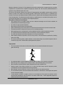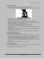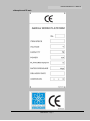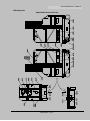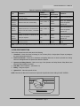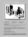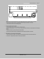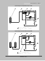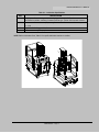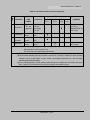
1
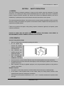
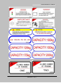
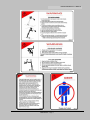
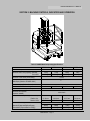
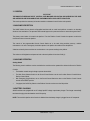
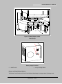
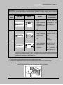
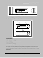
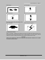
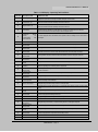
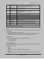
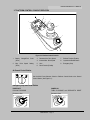
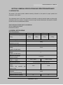
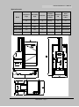
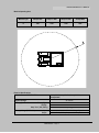
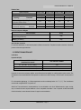
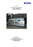
OPERATION AND SAFTY MANUAL MV060-E (AMWP6-1000) MV075-E (AMWP7.5-1000) (AMWP7.5-2000) (AMWP9-2000) OPERATION AND SAFTY MANUAL FOREWORD This manual is a very important tool! Keep it with the machine at all times. The purpose of this manual is to provide owners, users, operators, lessors, and lessees with the precautions and operating procedures essential for the safe and proper machine operation for its intended purpose. Due to continuous product improvements, the manufacturer reserves the right to make specification changes without prior notification. Contact the manufacturer for updated information. Other Publications Available: Illustrated Parts Manual AMWP SERIES Page 1 OPERATION AND SAFTY MANUAL SAFETY ALERT SYMBOLS AND SAFETY SIGNAL WORDS This is the Safety Alert Symbol. It is used to alert you to the potential personal injury hazards. Obey all safety messages that follow this symbol to avoid possible injury or death. DANGER INDICATES AN IMMINENTLY HAZARDOUS SITUATION. IF NOT AVOIDED, WILL RESULT IN SERIOUS INJURY OR DEATH. WARNING INDICATES A POTENTIALITY HAZARDOUS SITUATION. IF NOT AVOIDED, COULD RESULT IN SERIOUS INJURY OR DEATH. CAUTION INDICATES A POTENTIALITY HAZARDOUS SITUATION. IF NOT AVOIDED, MAY RESULT IN MINOR OR MODERATE INJURY. IT MAY ALSO ALERT AGAINST UNSAFE PRACTICES. IMPORTANT INDICATES PROCEDURES ESSENTIAL FOR SAFE OPERATION. WARNING THIS PRODUCT MUST COMPLY WITH ALL SAFETY RELATED BULLETINS. CONTACT THE MANUFACTURER OR IT’S LOCAL AUTHORIZED REPRESENTATIVE FOR INFORMATION REGARDING SAFETY-RELATED BULLETINS WHICH MAY HAVE BEEN ISSUED FOR THIS PRODUCT. IMPORTANT THE MANUFACTURER SENDS SAFETY RELATED BULLETINS TO THE OWNER OF RECORD OF THIS MACHINE. CONTACT THE MANUFACTURER TO ENSURE THAT THE CURRENT OWNER RECORDS ARE UPDATED AND ACCURATE. IMPORTANT THE MANUFACTURER MUST BE NOTIFIED IMMEDIATELY IN ALL INSTANCES WHERE IT’S PRODUCTS HAVE BEEN INVOLVED IN AN ACCIDENT INVOLVING BODILY INJURY OR DEATH OF PERSONNEL OR WHEN SUBSTANTIAL DAMAGE HAS OCCURRED TO PERSONAL PROPERTY OR THE PRODUCT. AMWP SERIES Page 2 OPERATION AND SAFTY MANUAL TABLE OF CONTENTS SUBJECT-SECTION, PARAGRAPH PAGE NO. FOREWORD………………………………………………………………………………………………………..1 SAFETY ALERT SYMBOLS AND SAFETY SIGNAL WORDS…………………………………………….....2 SECTION 1 - SAFETY PRECAUTIONS 1.1 1.2 1.3 1.4 1.5 GENERAL…………………………………………………………………… . ……………………………...6 PRE-OPERATION …………………………………………………………………………………………… .6 Operator Training And Knowledge……………………………………………………………………….…6 Workplace Inspection ………………………………………………………………………………………...6 Machine Inspection………………………………………………………………………………………… ..7 OPE RAT IO N ……………………… ……………… ……………… ……………… ……………… ………… . 7 G en e ral …………… … ………… …… ………… …… ………… …… …………… … …………… … ……… . . 7 Trip and Fall Hazard……………………………………………………………………………….……… ...7 Electrocution Hazard …………………………………………………………………………………….…..8 Safety Rules for Electrical Control System……………………………………………………………… .9 Tipping Hazard………………………………………….…………………………………….…9 Crushing And Collision Hazard…………………………………………………………………………….10 TOWING, LIFTING, AND HAULING…………………………………………………………………..….10 Plates and Warning Labels…………………………………………………………………………………10 Nameplate and CE mark……………………………………….………………………………………………………….11 Warning labels……………………………………………………………………………………………………………...12 SECTION 2 - PREPARATION AND INSPECTION 2.1 PERSONNEL TRAINING……………………………………………………………………………… ..……17 Operator Training…………………………………………………...……………………………………………17 Training Supervision………………………………………………………………………………………..……17 Operator Responsibility…………………………………………………………………………………………..17 2.2 PREPARATION, INSPECTION, AND MAINTENANCE……………………………………………………17 2.3 PRE-START INSPECTION………………………………………………...…………………………………...18 2.4 DAILY WALK-AROUND INSPECTION………………………………...……………………………………...19 2.5 FUNCTION CHECK…………………………………………………………...………………………………...20 SECTION 3 - MACHINE CONTROLS, INDICATORS AND OPERATION 3.1 GENERAL……………………………………………………………… ...………………………………………23 3.2 MACHINE DESCRIPTION………………………………………………...……………………………………23 3.3 MACHINE OPERATION………………………………………………...………………………………………23 Getting Started……………………………………………………………...……………………………………23 3.4 BATTERY CHARGING ………………………………………………...……………………………………….23 Battery Low Voltage Warning Indicators………………………………...…………………………………….24 To Charge Batteries………………………………………………………………………………………..…….25 AMWP SERIES Page 3 OPERATION AND SAFTY MANUAL 3.5 3.6 3.7 3.8 3.9 3.10 3.11 3.12 Battery Charging Status Indicators…………………………………………………….………………………….……….26 GROUND CONTROL STATION – OPERATION……...……………………………………………..……….27 Main Power Selector Switch………………………………………………………...…………………….……27 Emergency Stop/Shut Down Button…………………………………...………………………………………27 Brake Release Button……………………………………………………...…………………………………....27 Platform Up……………………………………………………………………………………………………….28 Platform Down…………………………………………………………………………………………..……….28 Manual Descent Control Valve…………………………………………………………………………………28 Machine Status LCD Display………………………………………………………………………….………..30 LCD Display Fault Conditions………………………………………………………………………….……….31 GROUND CONTROL STATION-PROGRAMMING…………………………………………….…..………..33 General………………………………………………………………………………………………… ..……….33 Programming Levels…………………………………………………………………………………..………..33 Operator Programming Mode…………………………………….…………………………………..………...33 Activating Programming Mode………………………………………………………………………...……….34 Entering Password……………………………………………………………………………………...……….35 Programming Mode Selection………………………………………………………………………….………36 Selecting Programmable Item to Adjust………………………………………………………………………36 Adjusting Programmable Setting…………………………………………….…………………………………37 PLATFORM CONTROL CONSOLE OPERATION…………………………………….……………………..38 At Ground Control Station………………………………………………………………………………………38 Emergency Stop/Shut-Down Button…………………………………………………………………..………38 Battery Charge/Fault Code LED Indicator……………………………………………………………………39 Driving Machine…………………………………………………………………………………………………3 9 Adjusting Maximum Drive Speed Control…………………………………………………………………….40 Elevating/Lowering the Platform……………………………………………………………………………....41 PARKING MACHINE…………………………………………………………………………………..………..42 PLATFORM CONFIGURATIONS……………………………………………………………………..……....43 FALL PROTECTION – LANYARD ATTACHMENT………………………………………………….……..…45 QUICK-CHANGE PLATFORM MOUNTING……………………………………………………….………....46 Platform Removal………………………………………………………………………………………………..46 Platform Installation………………………………………………………………………………… ..……….46 TRANSPORTING, LIFTING PROCEDURES………………………………………………………...………47 General……………………………………………………………………………………………………………4 7 Truck Transport…………………………………………………………………………………………………..47 Fork Lift Truck Transport………………………………………………………………………………………..48 SECTION 4 - EMERGENCY PROCEDURES 4.1 GENERAL INFORMATION……………………………………………………………………………………..49 4.2 EMERGENCY OPERATION…………………………………………………………………………………...49 Operator Unable to Control Machine………………………………………………………………………….49 Platform caught Overhead……………………………………………………………………………………...49 4.3 INCIDENT NOTIFICATION……………………………………………………………………………………..49 AMWP SERIES Page 4 OPERATION AND SAFTY MANUAL SECTION 5 - GENERAL SPECIFICATIONS AND OPERATOR MAINTENANCE 5.1 INTRODUCTION…………………………………………………………………………………………………50 5.2 GENERAL SPECIFICATIONS………………………………………………………………………………… .50 Machine Specifications……………………………………………………………………………….………………50 Machine Dimension ………………………………………………………………………………………… 5 1 Machine Operating Area……………………………………………………………………………………….52 Electrical Specifications…………………………………………………………………………………………52 Platform Data…………………………………………………………………………………………………… .53 Machine Component Weights………………………………………………………………………………….53 Serial Number Locations……………………………………………………………………………………….53 5.3 OPERATOR MAINTENANCE…………………………….…………………………………….………………53 Lubrication……………………………………………………………………………… ..………………………53 Hydraulic Diagram……………………………………………………………………………………………… 54 SECTION 6 - INSPECTION AND REPAIR LOG LIST OF FIGURES FIGURES NO. TITLE PAGE NO. 2-1. Daily Walk-Around Inspection for AMWP Machines………………………………………………………..20 3-1. Battery Charger Location……………………………………………………………………………………..24 3-2. Ground Control Station. (Machine Rear View) …………………………………………………………….29 3-3. Platform Control Console. …………………………………………………………………………………….38 3-4. Forklift Truck Lifting Pockets and Machine Tie Down Bar Locations………………………………….48 LIST OF TABLES TABLE NO. TITLE PAGE NO. 1-1 Minimum Safe Approach Distance (M.S.A.D.). ……………………………………………………………….8 2-1 Inspection and Maintenance Table……………………………………………………………….……………..18 3-1 Machine Operating Specifications……………………………………………...……………………………….22 3-2 Battery Low Voltage Warning Indicators………………………………………………………………………..25 3-3 LCD Display – Operating Fault Conditions…………………………………………...…………….………….32 3-4 Ground Control Station – Level 3 – Programmable Settings and Factory Presets………………………..34 5-1 Lubrication Specifications……………………………………………….……………………………………….55 5-2 Lubrication Intervals for Various Components………………………………………………….……………. 56 6-1 Inspection and Repair Log………………………………………………………………………..…… ……….57 AMWP SERIES Page 5 OPERATION AND SAFTY MANUAL SECTION 1. SAFETY PRECAUTIONS 1.1 GENERAL This section outlines the necessary precautions for proper and safe machine usage and maintenance. For proper machine use, it is mandatory that a daily routine be established based on the content of this manual. A maintenance program, using the information provided in this manual and the Service and Maintenance Manual, must also be established by a qualified person and must be followed to ensure that the machine is safe to operate. The owner/user/operator/lessor/lessee of the machine should not accept operating responsibility until this manual has been read, training is accomplished, and operation of the machine has been completed under the supervision of an experienced and qualified operator. If there are any questions with regard to safety, training, inspection, maintenance, application, and operation, please contact the manufacturer. WARNING FAILURE TO COMPLY WITH THE SAFETY PRECAUTIONS LISTED IN THIS MANUAL COULD RESULT IN MACHINE DAMAGE, PROPERTY DAMAGE, PERSONAL INJURY OR DEATH. 1.2 PRE-OPERATION Operator Training And Knowledge Read and understand this manual before operating the machine. Do not operate this machine until complete training is performed by authorized persons. Only authorized and qualified personnel can operate the machine. Read, understand, and obey all DANGERS, WARNINGS, CAUTIONS, and operating instructions on the machine and in this manual. Use the machine in a manner, which is within the scope of its intended application set by the manufacturer. All operating personnel must be familiar with the emergency controls and emergency operation of the machine as specified in this manual. Read, understand, and obey all applicable employers, local, and governmental regulations as they pertain to operation of the machine. Workplace Inspection The operator is to take safety measures to avoid all hazards in the work area prior to machine operation. Do not operate or raise the platform while on trucks, trailers, railway cars, floating vessels, scaffolds or other equipment unless approved in writing by the manufacturer. This machine can be operated in temperatures of –20℃ to 40℃. Consult the manufacturer for operation outside this range. AMWP SERIES Page 6 OPERATION AND SAFTY MANUAL Machine Inspection Before machine operation, perform inspections and functional checks. Refer to Section 2 of this manual for detailed instructions. Do not operate this machine until it has been serviced and maintained according to requirements specified in the Service and Maintenance Manual. Ensure all safety devices are operating properly. Modification of these devices is a safety violation. WARNING MODIFICATION OR ALTERATION OF AN AERIAL WORK PLATFORM SHALL BE MADE ONLY WITH PRIOR WRITTEN PERMISSION FROM THE MANUFACTURER Do not operate any machine on which the safety or instruction placards or decals are missing or illegible. Avoid any build up of debris on platform floor. Keep mud, oil, grease, and other slippery substances from footwear and platform floor. 1.3 OPERATION General Do not use the machine for any purpose other than positioning personnel, their tools and equipment, or for hand stock picking. Never operate a machine that is not working properly. If a malfunction occurs, shut down the machine. Never slam a control switch or lever through neutral to an opposite direction. Always return switch to neutral and stop before moving the switch to the next function. Operate controls with slow and even pressure. Do not allow personnel to tamper with or operate the machine from the ground with personnel in the platform, except in an emergency. Do not carry materials directly on platform railing unless approved by the manufacturer. Always ensure that power tools are properly stowed and never left hanging by their cord from the platform work area. Fully lower mast assembly and shut off all power before leaving machine. When performing welding operations at elevation, precautions must be taken to protect all machine components from contact with weld splatter or molten metal. Battery fluid is highly corrosive. Avoid contact with skin and clothing at all times. Charge batteries on in a well ventilated area. Trip and Fall Hazard The manufacturer recommends that the operator in the platform wear a full body harness with a lanyard attached to an authorized lanyard anchorage point. For further information regarding fall protection requirements on the products, contact the manufacturer. AMWP SERIES Page 7 OPERATION AND SAFTY MANUAL Before operating the machine, make sure all railing and gates are fastened in their proper position. Keep both feet firmly positioned on the platform floor at all times. Never use ladders, boxes, steps, planks, or similar items on platform to provide additional reach. Never use the mast assembly to enter or leave the platform. Use extreme caution when entering or leaving platform. Ensure that the mast assembly is fully lowered. Face the machine when entering or leaving the platform. Always maintain “three point contact” with the machine, using two hands and one foot or two feet and one hand at all times during entry and exit. Platform-to-structure transfers at elevated positions are discouraged. Where transfer is necessary, enter/exit through the gate only with the platform within 1 foot (0.3m) of a safe and secure structure. 100% tie-off is also required in this situation utilizing two lanyards. One lanyard must be attached to the platform with the second lanyard attached to the structure. The lanyard connected to the platform must not be disconnected until such time the transfer to the structure is safe and complete. Electrocution Hazard Table 1-1. Minimum Safe Approach Distance (M.S.A.D.) NOTE: VOLTAGE RANGE (PHASE TO PHASE) MINIMUM SAFE APPROACH DISTANCE-Feet (m) 0-50KV 10(3) Over 50KV to 200KV 15(5) Over 200KV to 350KV 20(6) Over 350KV to 350KV 25(8) Over 500KV to 750KV 35(11) Over 750KV to 1000KV 45(14) This Minimum Safe Approach Distance shall apply except where employer, local, or governmental regulations are more stringent. AMWP SERIES Page 8 OPERATION AND SAFTY MANUAL Maintain a clearance of at least 10 ft (3m) between any part of the machine and its occupants, their tools, and their equipment from any electrical line or apparatus carrying up to 50,000 volts. One foot (0.3m) additional clearance is required for every additional 30,000 volts or less. The minimum safe approach distance may be reduced if insulating barriers are installed to prevent contact, and if the barriers are rated for the voltage of the line being guarded. These barriers shall not be part of (or attached to) the machine. The minimum safe approach distance shall be reduced to a distance within the designed working dimensions of the insulating barrier. This determination shall be made by a qualified person in accordance with employer, local, or governmental requirements for work practices near energized equipment. Safety Rules for Electrical Control System Only personnel who are properly trained and have adequate knowledge and skill should undertake all electrical/electronic troubleshooting and repair. Do not alter or bypass protective interlocks. Before starting, read and observe all warning labels. When trouble shooting make sure the power source has been disconnected and main switch has been locked. Take extra precautions in damp areas to protect you from accidental grounding. Before applying power to any equipment it must be established, without a doubt, that all persons are clear. Do not open the electrical control panel unless it is necessary to check the electrical equipment. Do not alter the electrical circuits unless authorized to do so by the manufacturer. When replacing electrical components, make sure they conform to the manufacturer’s specifications, including proper color coding. Do not wear metal frame glasses, metallic necklaces or chains while working on any electrical equipment. Also do not wear any ring, watch or bracelet while operating electrical equipment. Tipping Hazard The user should be familiar with the surface before driving. Do not exceed the allowable side slope and grade while driving. Do not elevate platform or drive with platform elevated while on a slope, or on an uneven or soft surface. Before driving on floors, bridges, trucks, and other surfaces, check allowable capacity of the surfaces. Never exceed the maximum platform capacity. Distribute loads evenly on platform floor. Keep the chassis of the machine a minimum of 2 ft. (0.6m) from holes, bumps, drop-offs, obstructions, debris, concealed holes, and other potential hazards at the ground level. Never attempt to use the machine as a crane. Do not tie-off machine to any adjacent structure. Do not increase the platform size with unauthorized deck extensions or attachments, increasing the area exposed to wind will decrease stability. If mast assembly or platform is caught so that one or more wheels are off the ground, the operator must be removed before attempting to free the machine. Use cranes, forklift trucks, or other appropriate equipment to stabilize machine and remove personnel. AMWP SERIES Page 9 OPERATION AND SAFTY MANUAL Crushing And Collision Hazard Personal protection equipment must be worn by all operating and ground personnel. Check work area clearances above, on sides, and bottom of platform while driving and lifting or lowering platform During operation, keep all body parts inside platform railing. Always post a lookout when driving in areas where vision is obstructed. Keep non-operating personnel at least 6 ft. (1.8m) away from machine during all driving operations. Limit travel speed according to conditions of ground surface, congestion, visibility, slope, location of personnel, and other factors causing hazards of collision or injury to personnel. Be aware of stopping distances in restricted or close quarters or when driving in reverse. Do not drive at high speeds in restricted or close quarters or when driving in reverse. Exercise extreme caution at all times to prevent obstacles from striking or interfering with operating controls and persons in the platform. Ensure that operators of other overhead and floor level machines are aware of the aerial work platform’s presence. Disconnect power to overhead cranes. Warn personnel not to work, stand, or walk under a raised platform. Position barricades on floor as necessary. 1.4 TOWING, LIFTING, AND HAULING Never allow personnel in platform while towing, lifting, or hauling. This machine should not be towed, except in the event of emergency, malfunction, power failure, or loading/unloading. Refer to the Emergency Procedures Section of this manual for emergency towing procedures. Ensure platform is fully retracted and completely empty of tools prior to towing, lifting or hauling. Do not assist a stuck or disabled machine by pushing or pulling except by pulling at the chassis tie-down bars. When lifting machine with a forklift, position forks only at designated areas of the machine. Lift with a forklift of adequate capacity. Refer to the Machine Operation section of this manual for lifting information. 1.5 Plates and Warning Labels Upon unpacking, check the plates and warning labels. Do not operate the machine on which the plates or labels are missing or illegible. Contact the dealer immediately. The following plates are visible on the machine. AMWP SERIES Page 10 OPERATION AND SAFTY MANUAL ● Nameplate and CE mark AMWP SERIES Page 11 OPERATION AND SAFTY MANUAL ● Warning labels AMWP SERIES DECAL INSPECTION AMWP SERIES Page 12 OPERATION AND SAFTY MANUAL AWMP SERIES DECAL INSPECTION Part No. Description QTY. 9221015 Machinery label 1 9341013 Notice—Draw out to manual lower platform 1 9421011 Notice—Power 1 9421013 Notice—Tie down 2 9421015 Notice—Hook 2 9422011 Notice—Rated capacity of standard platform AMWP7.5:125kgs(single) Or Rated capacity of extension platform AMWP6:125kgs(single) Or Rated capacity of extension platform AMWP9:125kgs(twin) 1 9422013 Notice—Rated capacity of extension platform 7.5m:100kgs(single) 1 9422015 Notice—Rated capacity of standard platform AMWP6:150kgs(single) Or Rated capacity of standard platform AMWP9:150kgs(twin) 1 9422017 Notice—Rated capacity of extension platform AMWP7.5:175kgs(twin) 1 9422019 Warning—This machine must not be used until it is inspected and operating properly 1 9423011 Notice—Allowed number of persons: ONE 1 9423013 Important—Move with brake released 1 9423015 Danger—Electrocution hazard 1 9423017 Warning—Tip-over hazard 1 9423021 Warning—Crushing hazard Or Falling hazard Notice—Allowed number of persons: TWO 9411025 CE label 1 9441017 Notice—Charging usage 1 9441019 Warning—Timely charging 1 9441021 Danger—Please don′t stand 1 9441023 Warning—Here with fork 2 9441025 Notice—Tyre Max. capacity 350 kg 4 9441027 Warning—Here without fork 3 9443011 Notice—Rated capacity of standard platform AMWP7.5:200kgs(twin) 1 9443019 Notice—Recharging lasts at least 12 hours. 1 9443021 Notice—Please cut off the power after operating. 1 9443023 Label—Directional arrows 1 9423019 Decal Inspection: Use the pictures on the next page to verify that all decals are legible and in place. Below is a numerical list with quantities and descriptions. AMWP SERIES Page 13 1 1 OPERATION AND SAFTY MANUAL AMWP SERIES Page 14 OPERATION AND SAFTY MANUAL AMWP SERIES Page 15 OPERATION AND SAFTY MANUAL AMWP SERIES Page 16 OPERATION AND SAFTY MANUAL SECTION 2. PREPARATION AND INSPECTION 2.1 PERSONNEL TRAINING The aerial platform is a personnel-handling device; so it is necessary that it be operated and maintained only by trained personnel. Persons under the influence of drugs or alcohol or who are subject to seizures, dizziness or loss of physical control must not operate this machine. Operator Training Operator training must cover: 1. 2. 3. 4. 5. 6. 7. 8. Use and limitations of the controls in the platform and at the ground, emergency controls and safety systems. Control labels, instructions, and warnings on the machine. Rules of the employer and government regulations. Use of approved fall protection device. Enough knowledge of the mechanical operation of the machine to recognize a malfunction/ The safest means to operate the machine where overhead obstructions, other moving equipment, and obstacles, depressions, holes, drop-offs are present. Means to avoid the hazards of unprotected electrical conductors. Specific job requirements or machine application. Training Supervision Training must be done under the supervision of a qualified person in an open area free of obstructions until the trainee has developed the ability to safely control and operate the machine. Operator Responsibility The operator must be instructed that he/she has the responsibility and authority to shut down the machine in case of a malfunction or other unsafe condition of either the machine or the job site. NOTE: The Manufacturer or Distributor will provide qualified people for training assistance with the first unit(s) delivered and from that time forward as requested by the user or his/her personnel. 2.2 PREPARATION, INSPECTION, AND MAINTENANCE The following table covers the periodic machine inspections and maintenance recommended by the manufacturer. consult local regulations for further requirements for aerial work platforms. The frequency of inspections and maintenance must be increased as necessary when the machine is used in a harsh or hostile environment, if the machine is used with increased frequency, or if the machine is used in a severe manner. IMPORTANT THE MANUFACTURER RECOGNIZES A QUALIFIED MECHANIC AS A PERSON WHO HAS SUCCESSFULLY COMPLETED THE SERVICE TRAINING FOR THE SPECIFIC PRODUCT MODEL. AMWP SERIES Page 17 OPERATION AND SAFTY MANUAL Table 2-1. Inspection and Maintenance Table TYPE FREQUENCY Pre-Start Before using each day, or whenever there’s Inspection an Operator change. Pre-Delivery Inspection Before each sale, lease, or rental delivery. (See Note) PRIMARY SERVICE RESPONSIBILITY QUALIFICATION User or Operator User or Operator Owner, Dealer, or Qualified User Mechanic In service for 3 months or 150 hours, REFERENCE Operator and Safety Manual Service and Maintenance Manual and applicable Inspection form Service and Maintenance Frequent whichever comes first; or; Out of service for a Owner, Dealer, or Qualified Inspection period of more than 3 months; or Purchased User Mechanic Annually, no later than 13 months from the Owner, Dealer, or Qualified date of prior inspection. User Mechanic Preventative At intervals as specified in the Service and Owner, Dealer, or Qualified Service and Maintenance Maintenance Maintenance Manual. User Mechanic Manual used. Annual Machine Inspection Manual and applicable Inspection form Service and Maintenance Manual and applicable Inspection form NOTE: Inspection forms are available from the manufacture. Use the Service and Maintenance Manual to perform inspections. 2.3 PRE-START INSPECTION The Pre-Start Inspection should include each of the following: 1. Cleanliness – Check all surfaces for leakage (oil, fuel, or battery fluid) or foreign objects. Report any leakage to the proper maintenance personnel. 2. Decals and Placards – Check all for cleanliness and legibility. Make sure no decals or placards are missing. Make sure all illegible decals and placards are cleaned or replaced. . 3. Operators and Safety Manuals – Make sure a copy of the Operation and Safety Manual, Safety Manual, and Manual of Responsibilities is enclosed. 4. Daily Walk - Around Inspection – (See Section 2.4) 5. Battery – Charge as required. 6. Hydraulic Oil – Check the hydraulic oil level. NOTE: Check Service Manual for instructions and hydraulic oil specification before adding. DO NOT OVERFILL. AMWP SERIES Page 18 OPERATION AND SAFTY MANUAL 7. Function Check – Check all machine controls for operation. (See Section 2.5) If optional equipment is installed on this machine refer to Section 3 for specific Pre-Start Inspection and Operation instructions. 2.4 DAILY WALK-AROUND INSPECTION Begin the “Walk – Around Inspection” at item one (1) as noted on the diagram. Continue around machine check each item in sequence for the conditions listed in the following checklist. WARNING TO AVOID POSSIBLE INJURY, BE SURE MACHINE POWER IS “OFF” DURING “WALK-AROUND INSPECTION”. DO NOT OPERATE MACHINE UNTIL ALL MALFUNCTIONS HAVE BEEN CORRECTED. IMPORTANT DO NOT OVERLOOK VISUAL INSPECTION OF THE BASE FRAME UNDERSIDE. CHECK THIS AREA FOR OBJECTS OR DEBRIS, WHICH COULD CAUSE EXTENSIVE MACHINE DAMAGE. NOTE: On all components, make sure there are no loose or missing parts, that they are securely fastened, and that no visible damage, leaks or excessive wear exists in addition to any other criteria mentioned. 1. 2. 3. 4. 5. 6. 7. 8. 9. Drive and Caster Wheels – Check for any debris stuck to or around wheels. Base Frame – Check pot-hole-protection system components; check for loose wires or cables dangling below the base. Manual Descent Control Valve – See note above. Motor/Pump/Reservoir Unit – No evidence of hydraulic leaks. Batteries – Battery cables; no corrosion. Platform Assembly and Gate – Quick-Change platform mounting and mounting screws; platform fasteners; platform railings; entry bar or gate in proper working order. Platform Control console – Platform control; placards secure and legible; emergency stop switch reset for operation; Control markings legible. Ground Control Station – Main Power Selector Switch operable; placards secure and legible; emergency stop switch operates properly. Mast Assembly – Mast sections; slide pads; mast chains; sequencing cables; platform control and power cables (on side of mast); power cables properly tensioned and seated in sheaves; cable sheaves rotating freely. AMWP SERIES Page 19 OPERATION AND SAFTY MANUAL 9 8 7 6 5 4 3 2 Figure 2-1. Daily Walk-Around Inspection for AMWP Machines. 1. 2. 3. Drive and Caster Wheels Base Frame Manual Descent Control Valve 4. 5. 6. Motor/Pump/Reservoir Unit Batteries (Open Cover Doors) Platform Assembly 7. 8. 9. Platform Control Console Ground Control Console Mast Assembly 2.5 FUNCTION CHECK Once the “Walk-Around” Inspection is complete, perform a function check of all systems in an area free of overhead and ground level obstructions. Refer to Section 3 for more specific operating instructions. WARNING IF THE MACHINE DOES NOT OPERATE PROPERLY, TURN OFF THE MACHINE IMMEDIATELY! REPORT THE PROBLEM TO THE PROPER MAINTENANCE PERSONNEL. DO NOT OPERATE THE MACHINE UNTIL IT IS DECLARED SAFE FOR OPERATION. Perform a Function Check as follows: 1. From the ground controls with no load in the platform: a. Operate ground control functions, platform lift up and lift down. AMWP SERIES Page 20 OPERATION AND SAFTY MANUAL NOTE: Ensure Pot-Hole-Protection device is fully engaged (both bars down) when the platform is elevated. b. Ensure that all machine functions are disabled when the Emergency Stop Button is activated. c. Check Manual Control valve is operating properly. 2. From the platform control console: a. Ensure that the control console is properly mounted and secure. b. Raise and lower platform 2 ft. to 3 ft. (.61m to .92m) several times. Check for smooth elevation and lowering of platform. c. Operate all functions and check all limit and cutout switches. d. Ensure that all machine functions are disabled when the Emergency Stop Button is activated. 3. With platform in the transport (stowed) position: a. Drive the machine on a grade, not to exceed the rated grade ability, and stop to ensure the brakes hold. b. Check the 1.5 degree tilt sensor alarm to ensure proper operation. AMWP SERIES Page 21 OPERATION AND SAFTY MANUAL SECTION 3. MACHINE CONTROLS, INDICATORS AND OPERATION Table 3-1 AMWP-Machine Operating Specifications AMWP6-1000 Maximum Occupants: AMWP7.5-1000 AMWP7.5-2000 1~2 1 Maximum Work Load (Capacity): Standard: Extendible: 150kg 125kg 200kg 150kg 125kg 100kg 175kg 125kg 7.5m 9m Maximum Travel Grade (Grade ability): 15-20% Maximum Travel Grade (Side Slope):(Platform STOWED ONLY) 5° Maximum Height (Platform Stowed) Maximum Vertical Platform Height: 198cm 6m 7.5m Maximum Wheel Load (Per Wheel): 360kg Maximum Drive Speeds (Operator Variable): Max. Platform Speeds (w/Max. Load): Platform Up: Platform Down: Gross Machine Weight (Standard Equipment/Platform Empty): (Extendible Equipment/Platform Empty): AMWP9-2000 0.6.8-4 km/h 27-36 sec. 39-49 sec 62-73 sec 82-93 sec 30-35 sec. 40-45 sec 43-46 sec 53-56 sec 850kg 880kg 1100kg 1250kg 900kg 930kg 1160kg 1310kg AMWP SERIES Page 22 OPERATION AND SAFTY MANUAL 3.1 GENERAL IMPORTANT THE MANUFACTURER HAS DIRECT CONTROL OVER MACHINE APPLICATION AND OPERATION. THE USER AND OPERATOR ARE RESPONSIBLE FOR CONFORMING WITH GOOD SAFETY PRACTICES. This section provides the necessary information needed to understand control function and operation. 3.2 MACHINE DESCRIPTION The AMWP Model Lifts are electric self-propelled machines with an aerial work platform mounted to an elevating aluminum mast mechanism. The personnel lift’s intended purpose is to personnel access to areas above ground level. The primary control station is located in the platform. From the Platform Control Console the operator can drive the machine and raise or lower the platform. The controls of the programmable Ground Control Station are to be used during machine power-up, machine maintenance or in case of emergency should the operator in the platform be unable to lower the platform. Vibrations emitted by these machines are not hazardous to an operator working in the platform. The continuous A-Weighted sound pressure level at the work platform is less than 70db (A). 3.3 MACHINE OPERATION Getting Started The following control conditions must be met before the machine can be operated from either the Ground or Platform Controls. The batteries contain enough voltage to operate the machine. The Main Power Selector Switch on the Ground Control Station must be set for either Ground Control Mode or Platform Control Mode. Both Emergency Stop Switches, one on the Ground Control Station the other on the Platform Control Console must be in the RESET position. If equipped, the On/Off Key Switch on the Platform Console must be set to the ON position. 3.4 BATTERY CHARGING AMWP machines are equipped with an AC voltage input/DC voltage output battery charger. The charger automatically terminates charging when the batteries reach full capacity. NOTE: The machine’s platform drive function is disabled when the battery charger is plugged into an AC receptacle. AMWP SERIES Page 23 OPERATION AND SAFTY MANUAL Figure 3-1. Battery Charger Location. Battery Charger Battery Charger Front Panel 2. ON/OFF switch 3. AC Input Voltage Selector Battery Low Voltage Warning Indicators The Platform Control Console and Ground Control Station indicate battery low voltage at three (3) Warning Levels. AMWP SERIES Page 24 OPERATION AND SAFTY MANUAL Table 3-2. Battery Low Voltage Warning Indicators. IMPORTANT:The 3 Levels of Battery Low Voltage Warning indication will activate on Ground Control Modules and platform control console. Machines must follow the indicator guidelines and battery charging cycles to maximize battery life. WARNING LEVEL INDICATOR LOCATION PLATFORM CONTROL LED RESULT GROUND CONTROL LCD LEVEL-1 - + 00 00 0.0 LO W B A T TE R Y LEVEL-2 - + 00000.0 C H A R G E B A T TE R Y 38 LEVEL-3 - + 00 00 0.0 C H A R G E B A TT E R Y 39 ACTION REQUIRED TO CLEAR FAULT 3 LEDs/BARS flashing with an audible beep. Machine will Operate-No Control Functions Locked Out. Charge batteries to a level of four (4) LEDs/BARS or more before operating. 2 LEDs/BARS flashing with an audible beep. Platform Lift-UP Function is Locke Out. Charge batteries for a minimum of four (4) Continuous hours or eight (8) LEDs/BARS lit before Operating. (a) 1 LED/BAR Flashing with an audible beep. Drive and Platform Lift-UP Functions Locked Out. Charge batteries for a minimum of four (4) continuous hours or eight (8) LEDs/BARS lit before operating.(a) NOTE: (a) To maximize battery life, it is recommended that the factory supplied batteries be charged continuously for a minimum of 4 hours or until 8 bars are lit on the ground station LCD Display before operating the machine. When drained to Warning Level 2 or 3, batteries must be charged until 8 bars are lit on the ground station LCD display to clear the fault code. To Charge Batteries 1. 2. Park machine in a well ventilated area near an AC voltage electrical outlet. Check the AC voltage selector switch on front of the battery charger is set to correct local AC voltage. NOTE: The batteries on AMWP machines require approximately five (5) hours to fully charge when drained to LOW BATTERY VOLTAGE warning on the Ground Control Module LCD display. AMWP SERIES Page 25 OPERATION AND SAFTY MANUAL 3. Plug a heavy duty AC extension cord into the Charger AC Input Receptacle on the center rear cover of the machine. Battery Charging Status Indicators The battery charging status indicators are located just on the left of the Charger AC input receptacle on the center cover section at the rear of the machine.(See Figure 3-2.) When first plugged in, the charger runs through a self-diagnostic test, lighting the LEDs in sequence, then charging will begin. CHARGE COMPLETE GREEN (TOP) LED ON 100% Complete CHARGING AMBER (MIDDLE) LED ON Charging incomplete CHARGING PROBLEM RED (BOTTOM) LED ON Consult Troubleshooting Section of the Service Manual AMWP SERIES Page 26 OPERATION AND SAFTY MANUAL 3.5 GROUND CONTROL STATION-OPERATION (See Figure 3-2.) Main Power Selector Switch Set the Main Power Selector Switch to Ground Control Mode at the Ground Control Station Emergency Stop/Shut Down Button POWER OFF PUSH IN-To Engage Emergency Stop POWER ON TURN CLOCKWISE and RELEASE-To Reset Emergency Stop Brake Release Button PUSH and RELEASE-TO DISENGAGE Brakes PUSH and RELEASE AGAIN-TO ENGAGE Brakes NOTE: The brakes only DISENGAGE (electrically) when the joystick control is moved off center during driving or are manually DISENGAGED (electrically) using the Brake Release Button. If the machine’s batteries are completely depleted of electrical charge the brakes cannot be released manually. CAUTION DO NOT MANUALLY DISENGAGE THE BRAKES UNLESS MACHINE IS SETTING ON A LEVEL SURFACE OR MACHINE IS FULLY RESTRAINED. AMWP SERIES Page 27 OPERATION AND SAFTY MANUAL Platform Up PUSH IN-TO ELEVATE Platform Platform Down PUSH IN-TO LOWER Platform ↑ RELEASE-TO STOP ELEVATING RELEASE- TO STOP LOWERING Manual Descent Control Valve DRAW-OUT TO LOWER Platform RELEASE TO –STOP Platform Descent AMWP SERIES Page 28 OPERATION AND SAFTY MANUAL - 2 3 5 6 + 7 ↑ 10 9 4 8 Figure 3-2. Ground Control Station. (Machine Rear View) 1. Machine Status LCD Display 5. Platform Up 9. 10. Manual Descent Control Valve 2. Main Power Selector Switch 6. Platform Down 3. Emergency Stop 7. Battery Charging Status Indicators 4. Brake Release 8. Charger A/C Input Receptacle AMWP SERIES Page 29 Hydraulic Oil Reservoir OPERATION AND SAFTY MANUAL Machine Status LCD Display - + At power-up and during operation the LCD display on the Ground Control Module displays the current machine operating status. The following illustration explains the symbol indications. 2 - + x 00000.0 00 ↑ 3 4 xxxxx xxxxx xxxx xxxx xxxx xxxxx 00 5 LCD Display Symbols 1. 2. 3. 4. 5. Battery Charge Indicator (BCI) Function Display or Function Disabled Indicators Hour Meter Display Fault Code Indicator Fault Text Message Display (a) Note: (a) When a Fault Code is indicated the LCD screen will alternate between the text and symbol display modes. In the LCD Display Symbols illustration item (2), the Function Display or Function Disabled Indicators will vary as shown following: AMWP SERIES Page 30 OPERATION AND SAFTY MANUAL DRIVE Disabled LIFT UP Disabled LIFT DOWN Disabled Both LIFT UP and LIFT DOWN Disabled Drive Speed Cup-Back (Turtle) Mode Engaged (When Platform is Elevated) Battery Charger (AC) Plugged In - + LCD Display Fault Conditions Table 3-3, LCD Display – Operating Fault Conditions show common LCD display Fault indications which may occur during operation and are usually caused by either an error in machine operation or a work area condition. These fault conditions can usually be corrected by the operator and do not require a qualified mechanic to repair. IMPORTANT AFTER A FAULT CONDITION IS CORRECTED THE MACHINE POWER MAY NEED TO BE RECYCLED TO RESET THE GROUND CONTROL STATION. AMWP SERIES Page 31 OPERATION AND SAFTY MANUAL Table 3-3. LCD Display – Operating Fault Conditions Fault code Description of fault Conditions to check 01 Low Battery Voltage Battery cable ends loose or corroded at battery posts. Charger DC output wires from charger to batteries damaged or disconnected. 02 Left PHP Bar – Up Obstruction under Left pothole bar. Obstruction around the actuator assembly at the base of the mast. 03 Right PHP Bar – Up Obstruction under Right pothole bar. Obstruction around the actuator assembly at the base of the mast. 04 Tilt Condition If machine is on a tilt of more than the angle set in either or both the X or Y direction, this is normal operation. When the lift platform is raised then drive and lifting are disabled when tilt is detected. Check if Ground Station is mounted securely to the mast support column. 05 Obstruction Systemcommunication Ground Module 06 Reserved 07 Left Drive Motor Disconnected – 08 Right Drive Disconnected - 09 Left Brake – Disconnected Check left drive motor M1 connector at the Traction Module for secure and proper connection. 10 Right Brake – Disconnected Check right drive motor M2 connector at the Traction Module for secure and proper connection. 11 Left Drive Motor – Short Circuit Wiring harness from motor M1 connector on Traction module to left drive motor for damage. 12 Right Motor – Short Circuit Wiring harness from motor M2 connector on Traction module to right drive motor for damage. 13 Traction Module – In Foldback Machine is operating on a continuous grade or rough terrain 14 Pump Motor – Disconnected Check the positive and negative cables from the Ground Module to the Pump Motor studs for loose or corroded connections. 15 Lift Down ValveDisconnected Inspect wire terminals on the lift down valve wiring harness or a damaged lift down valve coil. 16 Lift Down Valve – Short Circuit Damaged wiring in the lift down valve wiring harness or a damaged lift down valve coil. 17 Ground Module – In Over temperature Pump is not being permanently driven Check heat sinking of Ground Module 18 Alarm – Short Circuit Damaged wiring in the alarm wiring harness or a damaged alarm. 19 Alarm – Disconnected Damaged wiring in the alarm wiring harness or a damaged alarm. Activate a function to check if alarm sounds 20 Beacon – Short Circuit Damaged wiring in the beacon wiring harness or a damaged beacon unit. 21 Beacon – Disconnected Is machine equipped with flashing beacon light. 22 Horn – Short Circuit Damaged wiring in the horn wiring harness or a damaged horn unit. 23 Horn - Disconnected Is machine connected with a horn. 24 Auxiliary 1 Circuit – Short Circuit Damaged wiring in the Auxiliary 1 Component wiring harness or a damaged component. 25 Auxiliary 1CircuitDisconnected Is machine equipped with a component on the Auxiliary 1 circuit. 26 Auxiliary 2 Circuit – Short Circuit Damaged wiring in the Auxiliary 2 Component wiring harness or a damaged component. 27 Auxiliary 2CircuitDisconnected Is machine equipped with a component on the Auxiliary 2 circuit 28 Reserved 29 Reserved Sensor No with Motor Is machine equipped with an Obstruction Sensor System? Check all cabling from the OSS module is undamaged. Check left drive motor M1 connector at the Traction Module for secure and proper connection. Check right drive motor M2 connector at the Traction Module for secure and proper connection. AMWP SERIES Page 32 OPERATION AND SAFTY MANUAL 30 Traction Module-No communication with Ground Module Check if the communications cable connections, P5 connector on the Ground Station and the round plug on the Traction Module are seated properly in their sockets at each end. Check the positive and negative power cable connections from the Ground Station to the Traction Module are tight and secure at both ends. 31 Platform Control Console – No communication with the Ground Module Check the harness connection at the P4 connector on the Ground Station and the harness connection at the other end on the Platform Junction Box. 32 Pump Motor – Over Current Platform overload condition. Obstruction in mast system. Pump positive and negative connections are secure and undamaged. Crushed or kinked hydraulic lines. Hydraulic leaks. 33 Both PHP Bars - Up Obstruction under left or right pothole bar. Obstruction around the actuator assembly at the base of the mast. 34 Aux 1 - Inhibit Auxiliary 1 switch input is active. 36 Aux 2 - Inhibit Auxiliary 2 switch input is active. 49 Aux 3 - Inhibit Auxiliary 3 switch input is active. 50 Aux 4 - Inhibit Auxiliary 4 switch input is active. Battery and harness connectors are secure and undamaged on the Ground Module. Batteries have sufficient charge. Confirm that the static ground strap attached under base frame is secure and undamaged. Damage to Platform Control Console wiring harness. Platform Control Console – 200 - 299 Check connections from the Platform Control Console down to the Ground Module. Fault Condition Confirm that the static ground strap attached under base frame is secure and undamaged. Traction Module – Damage to Traction Module wiring harness. 300 – 399 Fault Condition Confirm that the static ground strap attached under base frame is secure and undamaged. NOTE: The fault conditions shown above are fault conditions, which the Operator may be able to resolve. Should a fault occur and be displayed on the LCD screen which cannot be corrected at the Operator’s level, the problem must be referred to a qualified mechanic. A complete table of Fault Codes is listed in the Trouble Shooting Section of the Operation and Safty Manual.. 100 - 199 Ground Station – Fault Condition 3.6 GROUND CONTROL STATION – PROGRAMMING General The AMWP machine Ground Control Station allows on-board programming of various component and control function personality settings. Programming may be required under circumstances such as: Optional equipment has been added to the machine in the field and a function must be enabled before operation. Customizing the machine to fit a specific application, such as changing the LCD display language. Programming Levels There is one (1) password protected programming level available to the Operator: Level –3: Operator’s Settings Level –3 Password: 23456 Operator Programming Mode In the Operator Level Programming Mode the following items are shown on the main menu (See Table 3-4 for Setting Range and Default Factory Setting): Tilt Sensor Program Tilt Sensor Allows viewing current tilt sensor individual X and Y direction degree reading. Program Allows programming of the items shown in Table 3-4, the following is a brief explanation of each programming item. AMWP SERIES Page 33 OPERATION AND SAFTY MANUAL NOTE: There are two production modules available at this time, one for North/South American and European languages, and one for Asian languages. All programmable items between these modules are identical with the exception of language selection. Back To Main – When selected, will return to main level menu. Set Language – Selects the language that text on the LCD screen will be displayed. Set Sleep Time- Allows setting the length of time the machine will remain powered up without control input before powering itself down. Set Polarity of Keypad Code – Turns on or off the Programmable Security Lock switch circuit, if equipped. Enable Detection of Horn Open Circuit – Enables horn electrical circuit to be turned on (YES) or off (NO) if machine is equipped with a horn. Enable Detection of Beacon Open Circuit – Enables mast/base beacon strobe electrical circuits to be turned on (YES) or off (NO) if machine is equipped with either or both beacon strobes. Forward Alarm Disable – When turned on (YES) will disable the alarm when driving forward. Table 3-4. AMWP Ground Control Station – Level 3 – Programmable Settings and Factory Presets. Level-3: Operator Programmable Settings LEVEL On LCD Display: YES=√ HIGH=↑ NO=× LOW=↓ FACTORY PRESET PROGRAMMABLE ITEM 3 Back to Main 3 Set Language SETTING RANGE — Return to Main Menu 1 1- English 2- German 3- Dutch 4- French 5- Spanish 6- Italian 7- Swedish 8- Brazilian Portuguese 9- Finnish 2 1- English 2-Chinese 3-Japanese NOTE: There are two production modules available at this time, one for North/South American and European Languages, and one for Asian Languages. 3 Set Sleep Time 5 MINS 0-60 MINS 3 Set Polarity of the Keypad Code LOW HIGH/LOW 3 Enable Detection of Horn Open Circuit NO (a) YES/NO 3 Enable Detection of Beacon Open Circuit NO (a) YES/NO 3 Forward Alarm Disable NO YES/NO 3 OSS Diagnostics NO YES/NO Notes: (a) AMWP Models this feature is standard equipment and preset to YES at factory. Activating Programming Mode NOTE: If machine does not power up, check that both the Ground Control Station – Emergency Stop Button, and the Platform Control Console – Emergency Stop Button, are in the RESET position. AMWP SERIES Page 34 OPERATION AND SAFTY MANUAL 2 1. 2. 3. With machine power OFF, press and hold the Brake Release Button (1) on the Ground Control Station. While holding the Brake Release Button in, power machine up by turning the Main Power Selector Switch (2), to either the Ground Control or Platform Control Mode. Release the Brake Release Button (1) after machine is powered up. The LCD display should now display five zeros, one with a box around. Continue to next step Entering Password. Entering Password 4 00000 2 1. 2. 3. 4. 3 The Brake Release button (1) moves the box from left to right to select which digit to change. Platform UP button (2) increases the numerical digit. Platform DOWN button (3) decreases the numerical digit. Change all five digits (4) to match password level, then press the Brake Release button (1) again. AMWP SERIES Page 35 OPERATION AND SAFTY MANUAL Programming Mode Selection 2 RESET TIMERS PROGRAM ZERO TILT SENSOR 3 1. 2. 1 Use Platform UP/DOWN buttons (1) to move the selection box (2) up or down to select item to program. Press the Brake Release button (3) to enter selected mode then move on to Selecting Programmable Item to Adjust. Selecting Programmable Item to Adjust SET SLEEP TIME 2 1. 2. 1 Use the Platform UP/DOWN buttons (1) to scroll through the list of programmable items available to your programming level. Once a programmable item to be adjusted is selected, press the Brake Release button (2) to enter that settings’ adjustment mode. AMWP SERIES Page 36 OPERATION AND SAFTY MANUAL Adjusting Programmable Setting S MINS 2 1. 2. 1 Adjust the programmable setting using the platform UP/DOWN buttons (1), see Table 3-4 for range of settings for that item. Once parameter is set for the programmable item, press the Brake Release button (2), this will enter the parameter and return you to the Programmable Settings Menu. TO EXIT Programming Mode after adjusting programmable settings, power machine down with either the Main Power Selector Switch or Emergency Stop Button. AMWP SERIES Page 37 OPERATION AND SAFTY MANUAL 3.7 PLATFORM CONTROL CONSOLE OPERATION 4 5 7 2 8 3 6 9 Figure 3-3. Platform Control Console 1. 2. Battery Charge/Fault Code (LEDs) Max. Drive Speed Setting (LEDs) 3. 4. 5. 6. Decrease Max. Drive Speed Increase Max. Drive Speed Horn Drive Function (Enable) 7. 8. 9. Platform Function (Enable) Joystick with Enable Button Emergency Stop At Ground Control Station Set the Main Power Selector Switch to Platform Control Mode at the Ground Control Station. (See Figure 3-2.) Emergency Stop/Shut-Down Button POWER ON TURN CLOCKWISE and RELEASE-TO RESET Emergency Stop POWER-OFF PUSH IN-TO ENGAGE Emergency Stop AMWP SERIES Page 38 OPERATION AND SAFTY MANUAL Battery Charge/Fault Code LED Indicator On normal power-up and operation this series of LEDs visually indicates the amount of change left in the batteries. (+) GREEN LEDs lit indicate maximum charge. (-) RED LED’s lit indicate minimum charge remaining. The number of LEDs lit will change depending on the level of charge in the batteries. If battery voltage falls below 16.8 volts a fault condition will occur and the machine will stop operating. The batteries will need recharged. NOTE: LED Fault Code indications are in Table 3-3, LCD Display – Operating Fault Conditions, this section of the manual. Driving Machine WARNING WHEN DRIVING WITH PLATFORM LOWERED, DO NOT ATTEMPT TO DRIVE MACHINE UP A RAMP (GRADE) OF GREATER THAN TWENTY PER CENT (20%), AS TIPPING COULD OCCUR. POINT & GO® The Joystick can be moved in any direction off center. Drive Power is applied proportionally the further the Joystick is moved off center. 1. 2. Enter the platform. PRESS and RELEASE the Drive Function Button. The flashing LED indicates the function is active. The function remains active 3 to 4 seconds. AMWP SERIES Page 39 OPERATION AND SAFTY MANUAL 3. While the Drive Function is active. PRESS and HOLD the enable button on side the joystick. 4. Move the joystick the desired direction of travel. TO STOP the machine return the joystick back to center. Adjusting Maximum Drive Speed Control NOTE: When the platform is elevated the maximum drive speed is cut-back to 1/4th the speed when the platform is fully lowered. The Ground Control Module- LCD screen will display a turtle when in this mode, see Machine LCD Status Display in this section of the manual. Maximum Drive Speed Indicator Indicates current Maximum Drive Speed Setting. Slow to Fast. AMWP SERIES Page 40 OPERATION AND SAFTY MANUAL 1. Each Press of this button will reduce the Maximum Drive Speed allowed. (LESS LEDs Lit.) 2. Each Press of this button will increase the Maximum Drive Speed allowed. (MORE LEDs Lit.) Elevating/Lowering the Platform WARNING IF THE TILT ALARM HAS BEEN ACTIVATED, THE PLATFORM WILL NOT ELEVATE. ALSO IF THE TILT ALARM HAS BEEN ACTIVATED WHEN THE PLATFORM IS ELEVATED, THE DRIVE FUNCTION WILL BE DISABLED UNTIL THE PLATFORM IS COMPLETELY LOWERED. 1. Drive the machine to the area where overhead work is to be performed and position the machine into its approximate work position. 2. PRESS and RELEASE the Platform Function Button. The flashing LED indicates the function is active and will remain active 3 to 4 seconds. 3. While the Platform Function is active. PRESS and HOLD the Enable Button on side the Joystick. 4. Push the Joystick FORWARD from center TO ELEVATE the Platform. TO STOP platform movement return the joystick back to center. Pull the Joystick BACK from center TO LOWER the Platform. AMWP SERIES Page 41 OPERATION AND SAFTY MANUAL 5. If necessary, reposition (drive) lift using platform controller joystick to bring work object within reach. 3.8 PARKING MACHINE 1. 2. Drive machine to a well-protected and well-ventilated area. Ensure the platform is fully lowered, turn the main power selector switch to the OFF position (centered). NOTE: If required, charge batteries in preparation for next workday. AMWP SERIES Page 42 OPERATION AND SAFTY MANUAL 3.9 PLATFORM CONFIGURATIONS 4 3 2 STANDARD PLATFORM (AMWP) Model Max. Capacity AMWP6-1000 150kg AMWP7.5-1000 125kg AMWP7.5-2000 200kg AMWP9-2000 150kg 1. Gullwing Entry Gate 2. Entry Gate Latch 3. Lanyard Attach Point (on mast) 4. Platform Control Console AMWP SERIES Page 43 OPERATION AND SAFTY MANUAL 1 2 4 3 5 EXTENDIBLE PLATFORM (SLIDING BAR ENTRY ) Model Max. Capacity AMWP6-1000 125kg AMWP7.5-1000 100kg AMWP7.5-2000 175kg AMWP9-2000 125kg 1. Platform Control Console 2. Extension Slide/Lock Handle 3. Lanyard Attach Point (on mast) 4. Sliding Bar Entry Gate 5. Sliding Extendible Section AMWP SERIES Page 44 OPERATION AND SAFTY MANUAL 3.10 FALL PROTECTION – LANYARD ATTACHMENT CAUTION THE MANUFACTURER RECOMMENDS THE OPERATOR IN THE PLATFORM WEAR A FULL BODY HARNESS WITH A LANYARD ATTACHED TO AN AUTHORIZED LANYARD ANCHORAGE POINT. The main lanyard attach point for all AMWP machines is located on the lower right side of the mast platform header, just behind the operators platform. CAUTION AFTER ENTERING THE PLATFORM, BEFORE BEGINNING OPERATION ALWAYS CLOSE THE PLATFORM ENTRY GATE (S). AMWP SERIES Page 45 OPERATION AND SAFTY MANUAL 3.11 QUICK-CHANGE PLATFORM MOUNTING AMWP Model Lifts are equipped with quick-change platform mount, which allow quick removal and installation of currently available quick-change platform. NOTE: AMWP Models require the installation of the Quick-Change mount kit to use Quick-Chang Platforms. 2 3 4 1. 2. Upper Platform Mount Upper Mount Fasteners 3. 4. Lower Platform Mount Lower Mount Fasteners Platform Removal 1. 2. 3. Remove the platform control console from the platform and lay aside. Remove both upper and lower mount fasteners securing the platform support rails to the mast mounting channels. Swing and lift the platform out of the mounts and lay aside. Platform Installation 1. 2. 3. Set platform in upper and lower mounts. Install mount fasteners in upper and lower mounts. Attach platform control console to platform rail. WARNING ENSURE ALL FASTENERS ARE INSTALLED AND SECURE PRIOR TO OPERATION. AMWP SERIES Page 46 OPERATION AND SAFTY MANUAL 3.12 TRANSPORTING, LIFTING AND TIE DOWN PROCEDURES General All AMWP Series Model Personnel Lifts may be transported to a work site using the following methods: Driving the machine around on its base wheels if travel surface area permits. Loaded, IN AN UPRIGHT POSITION ONLY onto a heavy-duty vehicle with the payload capacity capable of supporting the full weight of the machine (Check machine gross weigh in the Operating Spec Chart at the beginning of this Section). Moved with a forklift truck using the forklift pockets in the base frame. Truck Transport CAUTION DO NOT TRANSPORT THE MACHINE IN A HORIZONTAL POSITION DUE TO LEAKAGE OF BATTERY ACID FROM THE BATTERIES OR HYDRAULIC FLUID FROM THE HYDRAULIC RESERVOIR. The machine may be winched onto a tilted roll-back truck bed (see important note following), which has been rolled back to ground level. Disengage the brakes and always winch (pull) from the mast (rear) end of the machine. IMPORTANT DO NOT ATTEMPT TO DRIVE MACHINE ONTO, OFF OF, OR PUSH MACHINE ONTO A TILTED ROLL-BACK TRUCK BED. THE AMWP MACHINES POWER MODULE COULD SUSTAIN SERIOUS DAMAGE WHEN THE UNIT IS PUSHED, OR TOWED AT SPEEDS GREATER THAN 2 MPH. WHEN TOWING OR WINCHING, THE MACHINE’S BRAKES MUST BE DISENGAGED. RE-ENGAGE THE BRAKES ONCE MACHINE IS IN PLACE WITH TRUCK BED LEVEL AND READY FOR TIE DOWN. Machine Tie-Down With machine in position to be tied down and brakes engaged, use the following guidelines for restraining the machine during transport. IMPORTANT USE OF EXCESSIVE FORCE WHEN SECURING MACHINE (DRIVE WHEEL LOAD), CAN CAUSE DAMAGE TO THE MACHINES DRIVE WHEEL COMPONENTS. 1. Secure machine with an adequate chain attached through the tie down loops located at the front and rear of machine. (See Figure 3-11.) 2. The chain should be securely tightened with a force of approximately 100 lb. applied two feet from the pivot handle. NOTE: Lifting devise must be capable of handling the gross weight of the machine, see the Operating Specifications table at the beginning of this Section. AMWP SERIES Page 47 OPERATION AND SAFTY MANUAL Fork-Lift Truck Transport All AMWP Model Lifts are equipped with wide forklift pockets running through the base frame. (See Figure 3-11.) This allows the machine to be either transported around a work area or lifted onto a higher level using a standard fork-lift truck. NOTE: Fork-lift trucks must be capable of handling the gross weight of the machine, see the Operating Specifications table at the beginning of this Section. 2 2 3 Figure 3-4. Forklift Truck Lifting Pockets and Machine Tie Down Bar Locations. 1. Rear Tie-Down Loop 2. Fork Lift Pockets AMWP SERIES Page 48 3. Front Tie-Down Loop OPERATION AND SAFTY MANUAL SECTION 4. EMERGENCY PROCEDURES 4.1 GENERAL INFORMATION This section explains the steps to be taken in case of an emergency situation during operation. 4.2 EMERGENCY OPERATION Operator Unable to Control Machine IF THE PLATFORM OPERATOR IS PINNED, TRAPPED OR UNABLE TO OPERATE OR CONTROL THE MACHINE: 1. Other personnel should operate the machine from ground controls only as required. 2. Only qualified personnel in the platform may use the platform controls. DO NOT CONTINUE OPERATION IF CONTROLS DO NOT FUNCTION PROPERLY. 3. Cranes, forklift trucks or other equipment can be used to remove the platform occupant and stabilize motion of the machine. Platform Caught Overhead If the platform becomes jammed or snagged in overhead structures or equipment, rescue the platform occupant prior to freeing the machine. 4.3 INCIDENT NOTIFICATION The manufacturer must be notified immediately of any incident involving an AMWP product. Even if no injury or property damage is evident, the factory should be contacted by telephone and provided with all necessary details. Failure to notify the manufacturer of an incident involving a product within 48 hours of such an occurrence may void any warranty consideration on that particular machine. IMPORTANT FOLLOWING ANY ACCIDENT, THOROUGHLY INSPECT THE MACHINE AND TEST ALL FUNCTIONS FIRST FROM THE GROUND CONTROL STATION, THEN FROM THE PLATFORM CONTROL CONSOLE. DO NOT LIFT ABOVE 10 FT. (3M) UNTIL YOU ARE SURE THAT ALL DAMAGE HAS BEEN REPAIRED, IF REQUIRED, AND THAT ALL CONTROLS ARE OPERATING CORRECTLY. AMWP SERIES Page 49 OPERATION AND SAFTY MANUAL SECTION 5. GENERAL SPECIFICATIONS AND OPERATOR MAINTENANCE 5.1 INTRODUCTION This section of the manual provides additional necessary information to the operator for proper operation and maintenance of this machine. The maintenance portion of this section is intended as information to assist the machine operator to perform daily maintenance tasks only, and does not replace the more thorough Preventive Maintenance and Inspection Schedule included in the Service and Maintenance Manual. Other Publications Available Specific to this Machine: Service and Maintenance Manual Illustrated Parts Manual 5.2 GENERAL SPECIFICATIONS Machine Specifications SPECIFICATION AMWP6-1000 AMWP7.5-1000 AMWP7.5-2000 AMWP9-2000 Gross Machine Weight (Platform Empty): 850kg 880kg 1100kg 1250kg Machine Height (Platform Stowed): 198cm Maximum Ground Pressure: (per wheel) 360kg Bearing Maximum Operating Incline: 1.5° Maximum Travel Grade (Grade ability): (Platform STOWED ONLY) Maximum Travel Grade Slope): (Platform STOWED ONLY) 15-20% (Side 5° Maximum Drive Speeds (Operator Variable): Maximum Base – Overall: (Width × Length) Maximum Wind Speed: Maximum Horizontal Manual Side Force: (Platform fully extended with Maximum load) 0.6-4 km/h 76cm×136cm 0 km/h-Machine rated for indoor use only 100 N 200 N Maximum Hydraulic System Pressure: (Recommended initial setting) Hydraulic Reservoir Capacity: 100cm×150cm 12MPa 5L AMWP SERIES 5L Page 50 OPERATION AND SAFTY MANUAL Machine Dimension The number of Max. working height height mm mm kg Person(s) mm mm Amwp6-1000 6000 7700 150 1 695×780 1360×790×1980 Amwp7.5-1000 7500 9200 125 1 695×780 1360×790×1980 Amwp7.5-2000 7500 9200 200 1 695×1000 1500×1000×1980 Amwp9-2000 9000 10700 150 1 695×1000 1500×1000×1980 Model Rated load persons allowed on platform AMWP SERIES Page 51 Platform size Stored Max. platform A×B dimension L×W×H OPERATION AND SAFTY MANUAL Machine Operating Area Machine Type Amwp6-1000 Amwp7.5-1000 Amwp7.5-2000 Amwp9-2000 R 1350 1350 1500 1500 Electrical Specifications SPECIFICATION Amwp6-1000,Amwp7.5-1000,Amwp7.5-2000, Amwp9-2000, System Voltage: 24 Volts DC Battery Specifications: Battery Type: Voltage: Amp Hour (AH) Rating: Battery Charger (DC Models) Input: Output: AMWP SERIES 12 Volts DC 100 Amp Hr. @20Hr. 120/240 Volts AC-50/60 Hz –Voltage Selectable 24 volt, 20 Amp Output – with 2 Amp Finish Page 52 OPERATION AND SAFTY MANUAL Platform Data SPECIFICATION Amwp6-1000 Occupants: (Persons allowed in Platform) Maximum Work Load (Capacity): Amwp7.5-1000 Amwp7.5-2000 1 Standard: Extendible Platform Height – Mast Fully Extended – (Ground to Platform Floor): Platform Cycle Performance: Lift Up: (in seconds, rated load ) Lift Down: Amwp9-2000 1-2 150kg 125kg 200kg 150kg 125kg 100kg 175kg 125kg 6m 7.5 m 7.5 m 9m 27-36 sec. 39-48 sec. 62-73 sec. 82-93 sec. 30-35 sec. 40-45 sec. 43-46 sec. 53-56 sec. Machine Component Weights SPECIFICATION Platform : (Quick-Change Platforms) Amwp Standard Platform: 32kg Battery: (per battery) 20kg Serial Number Locations For machine identification, a serial number plate is affixed to the machine. The plate is located on the back of the mast, just above the mast support bracket. 5.3 OPERATOR MAINTENANCE Lubrication Hydraulic Oil (HO) HYDRAULIC SYSTEM OPERATING TEMPERATURE RANGE SAE VISCOSITY GRADE +0°F to +180°F (-18 ℃-83℃) 10W +0°F to +210°F (-18 ℃-99℃) 10W-20, 10W-30 +0°F to +210°F (-18 ℃-99℃) 20W-20 Hydraulic oils must have anti-wear qualities, and sufficient chemical stability for mobile hydraulic system service. The manufacturer recommends Mobil fluid 424 hydraulic oil, which has an SAE viscosity of 10W-30 and a viscosity index of 152. For cold weather applications, i.e. When temperatures remain consistently below +20°F (-7℃) The manufacturer recommends using Mobil DTE 13 hydraulic oil. Aside from The manufacturer’s recommendations, it is not advisable to mix oils of different brands or types, as they may not contain the same required additives or be of comparable viscosities. If use of hydraulic oil other than Mobil fluid 424 is desired, contact the manufacturer for proper recommendations. AMWP SERIES Page 53 OPERATION AND SAFTY MANUAL Hydraulic Diagram (for amwp6-1000 and amwp7.5-1000) 5 4 3 2 Pump unit 2-Emergency Valve 3-Magnetic valve 4-Pipe 5 Cylinder 6-Throttle Hydraulic Diagram (for amwp7.5-2000 and amwp9-2000) 5 4 3 6 Pump Unit 2-Emergency Valve 3-Magnetic Valve 4-Pipe 5-Cylinder 6-Throttle AMWP SERIES Page 54 2 OPERATION AND SAFTY MANUAL Table 5-1. – Lubrication Specifications KEY SPECIFICATIONS MPG- Multipurpose Grease having a minimum dripping point of 350°F. Excellent water resistance and adhesive qualities, and being of extreme pressure type. (Timken OK 40 pounds minimum.) EPGL- Extreme Pressure Gear Lube (oil) meeting API service classification GL-5 or MIL -Spec MIL –L-2105. HO- Hydraulic Oil. ISO-Vg grade 32, 46. CL- Chain Lube. Use a good quality chain lubricant NOTE: Refer to Lubrication Chart, Table 5-2 for specific lubrication locations on machine 4 3 2 AMWP SERIES Page 55 OPERATION AND SAFTY MANUAL ITEM Table 5-2. Lubrication Intervals for Various Components COMPONENT NO/TYPE(a) LUBE POINTS 1 Hydraulic oil 2 3 4 Fill the Reservoir INTERVAL (b) LUBE/METHOD 3 MONTHS 2 MONTHS YEARS YEARS √ 2-Grease Fittings MPG-Pressure Gun √ Swivel Raceways 2-Front Casters MPG-Pressure Gun √ Mast Chains 2-Per Mast Section CL-Brush Spray Notes: 1 HO-Check Hyd. Oil Level HO-Change Hyd. Oil Caster Axles Key to Lubricants: 6 or √ COMMENTS Check fluid level every day. (c) Change hydraulic oil every 1 year. Inspect, lubricate if dry or rusting. MPG- Multipurpose Grease HO- Hydraulic Oil – ISO-Vg grade 32, 46. CL- Chain Lube. Use a good quality chain lubricant (a) Be certain to lubricate like items on each side of the machine. (b) Recommended lubricating intervals are based on normal use. If machine is subjected to severe operating conditions, such as a high number of cycles, location, corrosive/dirty environment, etc., user must adjust lubricating requirements accordingly. (c) Prior to checking hydraulic oil level, operate machine through one complete cycle of lift function (full up and down). Failure to do so will result in incorrect oil level reading on the hydraulic reservoir. AMWP SERIES Page 56 OPERATION AND SAFTY MANUAL SECTION 6. INSPECTION AND REPAIR LOG Machine Serial Number: Table 6-1. Inspection and Repair Log Date Comments AMWP SERIES Page 57 OPERATION AND SAFTY MANUAL Table 6-1. Inspection and Repair Log Date Comments AMWP SERIES Page 58 OPERATION AND SAFTY MANUAL BATTERY WARNING Battery posts, terminals and related accessories contain lead and lead compounds, chemicals known to cause cancer and reproductive harm. Batteries also contain other harmful chemicals. WASH HANDS AFTER HANDLING! AMWP SERIES Page 59