1
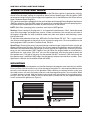
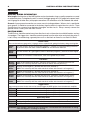
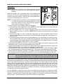
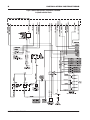
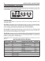
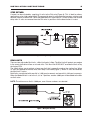
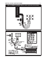
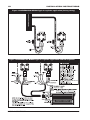
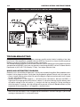
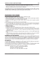
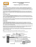
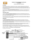
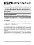
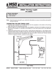
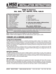
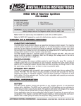
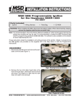
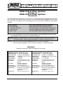
MSD DIS-2 Plus Ignition
PN 62112
MSD DIS-4 Plus Ignition
PN 62152
The MSD Digital DIS-2 Plus Ignition can be used on 4-cylinder engines equipped with two dual output
coils. The DIS-4 Plus Ignition can be used on 4, 6 or 8-cylinder engines equipped with up to four
dual output coils. The Ignitions will accept trigger inputs from electronic distributorless type ignition
systems.
Parts Included
1 - MSD DIS Ignition
12 - Connectors, Butt Splice
1 - Cable Assembly
1 - Bypass Plug
Parts not included but may be needed
Ignition Adapter(s) PN 8912, PN 89121, PN 8917
Coil Interface Modules, PN 8870 for GM DIS Applications
Coil Interface Modules, PN 8879 for Saturn Applications
Cam Sync Adapter, PN 8914 for Saturn Applications
Note: It is recommended that you have the Service Manual and wiring diagram for your vehicle before beginning the installation of the MSD DIS Ignition.
WARNING:Before installing the Ignition, disconnect the battery cables. When disconnecting the battery cables, always remove the Negative (-) cable first and install it last.
NOTES:1. Solid Core spark plug wires cannot be used with an MSD DIS Ignition.
2. Vehicles originally equipped with a CD ignition cannot use an MSD DIS Ignition.
IMPORTANT
Read these instructions before attempting this installation!
TECHNICAL FEATURES - DIGITAL DIS-2 PLUS
Operating Voltage: 12-18 volts (neg. ground)
Operating Current: 5.3 Amperes @ 10,000 RPM
RPM Capability:
14,000 RPM - 4-Cyl. @ 14 volts
Ignition Inputs:
2 - DIS Type
Ignition Outputs:
2 - DIS Type
LED Indicator:
Ign. trigger, low battery voltage
Tach Output:
(+) 12 volt square wave, 40°
Duration
Rev Limiter:
High RPM - Adjustable
Low RPM - Adjustable
Spark Duration:
20°- 4-Cyl. Max Sparks - 12
Energy Output Max: 105-115 milliJoules per spark.
Output Voltage:
Primary (into coil): 460-480 volts
Secondary: (w/stock coil)
43,000 volts
Weight & Size:
3 lbs., 9.5"L x 4.5"W x 2.2"H
MSD
IGNITION
TECHNICAL FEATURES - DIGITAL DIS-4 PLUS
Operating Voltage: 12-18 volts (neg. ground)
Operating Current: 10 Amperes @ 10,000 RPM
RPM Capability:
14,000 RPM - 4, 6, 8-Cyl. @ 14 volts
Ignition Inputs:
2, 3, 4 - DIS Type
Ignition Outputs:
2, 3, 4 - DIS Type
LED Indicator:
Ign. trigger, low battery voltage
Tach Output:
(+) 12 volt square wave, 40°
Duration
Rev Limiter:
High RPM - Adjustable
Low RPM - Adjustable
Spark Duration:
20°- 4, 6, 8-Cyl. Max Sparks - 12
Energy Output Max: 105-115 milliJoules per spark.
Output Voltage:
Primary (into coil): 460-480 volts
Secondary: (w/stock coil)
43,000 volts
Weight & Size:
3 lbs., 9.5"L x 4.5"W x 2.2"H
• w w w . m s d i g n i t i o n . c o m • ( 9 1 5 ) 8 5 7 - 5 2 0 0 • FA X ( 9 1 5 ) 8 5 7 - 3 3 4 4
INSTALLATION INSTRUCTIONS
THEORY OF OPERATION
CAPACITIVE DISCHARGE
The MSD Digital DIS Series Ignitions feature a capacitive discharge ignition design. The majority of
stock ignitions are inductive ignitions. In an inductive ignition, the coil must store and step up the
voltage to maximum strength in between each firing. At higher rpm, since there is less time to charge
the coil to full capacity, the voltage falls short of reaching maximum energy which results in a loss of
power or top end miss.
The MSD Ignition features a capacitor which is quickly charged to 460-480 volts and stores it until
the ignition is triggered. With the CD design, the voltage sent to the coil is always at full power even
at high rpm.
MULTIPLE SPARKS
The MSD Digital DIS Series Ignition produces full power multiple sparks for each firing of the spark
plug. The number of sparks that occur decreases as rpm increases, however the spark series always
lasts for 20° of crankshaft rotation. Above 3,000 rpm there is simply not enough time to fire the spark
plug more than once, so there is only one powerful spark.
REV LIMITER
The MSD DIS-2 and DIS-4 Ignitions are equipped with a built-in adjustable Soft Touch Rev Control. This
rev limit feature can be adjusted in 100 rpm increments using the program switches on the ignition's
end panel. The Soft Touch circuitry provides a smooth and accurate rev limit by dropping the spark
to individual cylinders. The Soft Touch produces a load-free rev limit that is accurate to within 10 rpm
of the selected rpm.
GENERAL INFORMATION
BATTERY
An MSD Digital DIS Series Ignition will operate on any negative ground, 12 volt electrical system
without a distributor. The MSD can be used with a 16 volt battery and can withstand a momentary 24
volts in case of a jump start. The ignition will deliver full voltage with a supply of 12 - 18 volts and will
operate with a supply voltage as low as 8 volts.
If your application does not use an alternator, allow at least 15 amp/hour for every half hour of operation.
If the engine is cranked with the same battery or other accessories such as an electric fuel pump, fan
or water pump are used, the amp/hour rating of the battery must be increased.
COILS
The MSD Digital DIS Ignitions can be used with most stock coils and most aftermarket coils that are
designed to replace the stock coils. If you have any questions concerning coils, contact our MSD
Customer Service Department at (915) 855-7123.
TACHOMETERS/FUEL INJECTION
The MSD Digital Series Ignitions feature a Tach Output Terminal on the side of the unit. This terminal
provides a trigger signal for tachometers, fuel injection, a shift light or other add-on devices that require
a 12 volt square wave rpm signal with a 20° duration.
Some vehicles may require an Ignition Adapter to operate properly with the MSD. For more information
on MSD Ignition Adapters, refer to page 13.
NOTE: If you plan on welding on your vehicle, to avoid possible damage to the ignition, always
disconnect both MSD Heavy Power cables from the battery. It is also recommended that the
tach ground wire be disconnected.
MSD
IGNITION
• w w w . m s d i g n i t i o n . c o m • ( 9 1 5 ) 8 5 7 - 5 2 0 0 • FA X ( 9 1 5 ) 8 5 7 - 3 3 4 4
INSTALLATION INSTRUCTIONS
SPARK PLUGS AND WIRES
Spark plug wires are very important to the operation of the DIS Series Ignition. A good quality, helically
wound wire and proper routing are required to obtain the best performance from the ignition. MSD
recommends using a helically wound suppression type wire such as the MSD 8mm Heli-Core or 8.5mm
Super Conductor Spark Plug Wire.
This type of wire provides a good path for the spark to follow while keeping Electro Magnetic Interference
(EMI) to a minimum. Excessive EMI, such as the amount that is produced by solid core spark plug wires,
will interfere with the operation of the MSD or other electronics on the vehicle.
NOTE: Solid Core spark plug wires cannot be used with an MSD Ignition.
Routing: Correct routing of the plug wires is also important to performance. Wires should be routed
away from sharp edges and engine heat sources. If there are two wires that are next to each other in
the engine's firing order, the wires should be routed away from each other to avoid inducing a spark
into the other wire.
To add more heat protection to the wires, MSD offers Pro Heat Guard, PN 3411. This is a glass woven
and silicone coated protective sleeve that can be slid over the plug wires. For extra protection to the
spark plug boots, MSD also offers Pro-Boot Guard, PN 3412.
Spark Plugs: Choosing the correct spark plug design and heat range is important when trying to get
the best performance possible. Since there are so many engine combinations and manufacturers,
MSD does not recommend which plug or gap is exactly right for your application. Platinum style spark
plugs are not recommended. MSD suggests that you follow the engine builder or manufacturer’s
specification for spark plugs. With that, you can then experiment with the plug gap to obtain the
best performance. The gap of the plugs can be opened in 0.005” increments, then tested until the
best performance is obtained. MSD judges the plug gap by compression and other variables. Every
application is different and should be tested and tuned.
MOUNTING
The MSD Ignition may be mounted in any location except on the engine or near the exhaust manifold.
Excessive heat at these locations may cause damage to the ignition. It is not recommended to mount
the unit in an enclosed area such as the glovebox. When selecting a mounting location, make sure
the cable harness will reach the battery and coils and the programming dials are accessible. When
a suitable location is found, hold the ignition in place and mark the location of the mounting holes.
Using a 13/64” drill bit, drill a hole in each of the locations marked and use the supplied hardware
screws to mount the ignition unit (Figure 1).
Figure 1 Mounting the DIS Ignition.
MSD
IGNITION
• w w w . m s d i g n i t i o n . c o m • ( 9 1 5 ) 8 5 7 - 5 2 0 0 • FA X ( 9 1 5 ) 8 5 7 - 3 3 4 4
INSTALLATION INSTRUCTIONS
WIRING
GENERAL WIRING INFORMATION
Wire Length: All of the wires of the MSD Ignition may be shortened as long as quality connectors are used
or soldered in place. To lengthen the wires, use one size bigger gauge wire (12 gauge for the power leads
and 16 gauge for all other wires) with proper connections. All connections must be soldered and sealed.
Grounds: A poor ground connection can cause many frustrating problems. When a wire is specified to
go to ground, it should be connected to the battery negative terminal, engine block or chassis. There
should always be a ground strap between the engine and the chassis. Always securely connect the
ground wire to a clean, paint free metal surface.
ROUTING WIRES
The MSD wires should be routed away from direct heat such as the exhaust manifolds/headers and any
sharp edges. The trigger wires should be routed separate from the other wires and spark plug wires. It
is best if they are routed along a ground plane such as the block or firewall as an electrical shield.
Power Leads
These are the two heavy guage wires (14 guage) and are responsible for getting direct battery voltage to the ignition.
Heavy
Red
This wire connects directly to the battery positive (+) terminal, to a positive battery junction or
the positive side of the starter solenoid. NOTE: Do not connect to alternator.
Heavy
Black
This wire connects to a good ground, either at the battery negative (-) terminal or to the engine.
Red
Connects to a switched 12 volte source, such as the ignition key or switch.
Coil Wires
Brown/
Orange
There are two Brown/Orange wires. Connects to the positive (+) terminal/wire of the coil.
NOTE: This is the only wire that makes electrical contact with coil positive (+).
Brown/
White
Connects to the negative (-) terminal/wire of the coil (Channel 1).
NOTE: This is the only wire that makes electrical contact with channel 1 coil negative (-).
Brown/
Green
Connects to the negative (-) terminal/wire of the coil (Channel 2).
NOTE: This is the only wire that makes electrical contact with channel 2 coil negative (-).
Brown/
Yellow
Connects to the negative (-) terminal/wire of the coil, (Channel 3 available on DIS-4 only).
NOTE: This is the only wire that makes electrical contact with channel 3 coil negative (-).
Brown/
Violet
Connects to the negative (-) terminal/wire of the coil, (Channel 4 available on DIS-4 only).
NOTE: This is the only wire that makes electrical contact with channel 4 coil negative (-).
Trigger Wires
There are two or more circuits that can be used to trigger the MSD Ignition; from the electronic amplifier.
This wire is used to connect to the electronic ignition amplifier output of channel 1.
White
This wire is used to connect to the electronic ignition amplifier output of channel 2.
Green
This wire is used to connect to the electronic ignition amplifier output of channel 3.
Yellow
This wire is used to connect to the electronic ignition amplifier output of channel 4.
Violet
Accessory Wires
Brown
Blue
Pink
Ignition interrupt/theft deterrent. To activate, connect this wire to ground through a switch.
Two Step feature. To activate low rpm limit, connect this wire to 12 volts.
Step Retard. To activate the step retard connect this wire to 12 volts.
Warning: High Voltage is present on the coil terminals. Do not touch the coil terminals or wiring when the engine is cranking or running.
MSD
IGNITION
• w w w . m s d i g n i t i o n . c o m • ( 9 1 5 ) 8 5 7 - 5 2 0 0 • FA X ( 9 1 5 ) 8 5 7 - 3 3 4 4
INSTALLATION INSTRUCTIONS
WIRING
NOTE: The factory rev limiter and all timing functions will still
function as normal with the MSD Digital DIS-Ignition
installed.
Locate the ignition coils and identify which wire leading to the
coil(s) has 12 volts on it with the ignition key in the On position. If
available, refer to the vehicle's service manual wiring diagram to
assist you in identifying the 12 volt wire(s).
NOTE: On some vehicles the starter must be engaged to provide
+12 volts to the positive wire leading to the coils. If none
of the wires indicate 12 volts, have someone engage the
starter while testing each of the wires.
Figure 2 Locating 12 Volts at the coil.
If a service manual is not available, follow this procedure
A.Disconnect all wires leading to the coil(s). NOTE: On some applications it may require that the
harness leading to the coil be cut to access the wires.
B.Turn the ignition switch on. Using a voltmeter, probe each of the wires on the harness to
determine which wire has 12 volts on it. NOTE: Make sure the wires do not contact any engine
components.
C.The wire that shows 12 volts is the positive feed to the coil. Turn the ignition switch Off and
connect the DIS Red wires to the harness and the DIS Brown/Orange wires to the positive (+)
side of the coil.
D.The remaining wires on the harness are the trigger wires. On a 4-cylinder you should have two,
on a 6-cylinder three, and on a 8-cylinder there should be four. Each of these wires needs to be
connected to one of the trigger input wires of the DIS Ignition. Using Figure 3 and 4 as a guide,
connect the DIS trigger input and coil (-) wires as follows.
1.Connect the DIS White wire, Channel 1, to the first factory trigger wire and then connect the DIS
Brown/White Coil (-) wire to the corresponding wire on the coil.
2.Connect the DIS Green wire, Channel 2, to the second factory trigger wire and then connect the
DIS Brown/Green Coil (-) wire to the corresponding wire on the coil.
3.Connect the DIS Yellow wire, Channel 3, (available on the DIS-4 only) to the third factory trigger
wire and then connect the DIS Brown/Yellow Coil (-) wire to the corresponding wire on the coil.
4.Connect the DIS Violet wire, Channel 4, (available on the DIS-4 only) to the fourth factory trigger
wire and then connect the DIS Brown/Violet Coil (-) wire to the corresponding wire on the coil.
IMPORTANT: If you are using the DIS-4 on a 4 or 6-cylinder application where all the DIS channels are
not used, you must ground the unused trigger input wires. On a 6-cylinder application,
ground the DIS Violet wire and on a 4-cylinder, ground the DIS Violet and Yellow wires.
At this point all the DIS harness wires should be connected. Review your wiring and make any
corrections if required. To verify that all wires are connected to their proper locations, plug the supplied
bypass plug into the DIS harness and then start the vehicle. If the vehicle does not start then the
harness was not installed properly. Check all your connections to ensure that they are secure and
connected in the proper order. The only wires that should be connected directly to the coil are the
BRN/ORG, BRN/WHT, BRN/GRN, BRN/YEL and the BRN/VIO. Do not hook any other wires to the coil.
The Red wires should be connected to a switched 12 volt source, allowing the ignition to be switched
On and Off by the vehicle's ignition switch.
In most applications, when the vehicle starts, that indicates that the harness is correctly installed.
Connect the DIS heavy Red wire to the positive (+) battery terminal and the heavy Black wire to the
negative (-) battery terminal. Remove the bypass plug from the harness and plug the DIS Ignition
into the harness. Start the vehicle to verifiy that all functions are operating.
MSD
IGNITION
• w w w . m s d i g n i t i o n . c o m • ( 9 1 5 ) 8 5 7 - 5 2 0 0 • FA X ( 9 1 5 ) 8 5 7 - 3 3 4 4
INSTALLATION INSTRUCTIONS
Figure 3 General Wiring Before Installation of the MSD.
6-Cylinder with Coil Packs
MSD
IGNITION
• w w w . m s d i g n i t i o n . c o m • ( 9 1 5 ) 8 5 7 - 5 2 0 0 • FA X ( 9 1 5 ) 8 5 7 - 3 3 4 4
INSTALLATION INSTRUCTIONS
Figure 4 General Wiring After Installation of the MSD.
6-Cylinder with Coil Packs
MSD
IGNITION
• w w w . m s d i g n i t i o n . c o m • ( 9 1 5 ) 8 5 7 - 5 2 0 0 • FA X ( 9 1 5 ) 8 5 7 - 3 3 4 4
INSTALLATION INSTRUCTIONS
PROGRAMMABLE FEATURES
The DIS Ignitions provide several programmable features that are set using the seven rotary dials
on their end panel. The DIS Ignitions are programmed at the factory for operation on most 4, 6 or
8-cylinder engines with distributorless ignitions.
Figure 5 Programming Rotary Switches.
Ignition Mode
The first dial, Ignition Mode, has several features and must be set to configure the MSD to match
your ignition system.
Waste Spark: If the ignition system uses dual tower coil packs, the system is a Waste Spark (WS).
This means that each side of the coil is fired but only one cylinder is under compression, so the other
spark is ‘wasted’. For these systems, you will select one of the WS On positions.
If you are incorporating a coil-per-cylinder ignition system, select a WS Off position.
Plus 4K or ØK: Each of the Ignition Mode selections shows Plus 4K or ØK. This will add either 4,000
rpm to the Max rev limit that you set or will leave the rpm limit at the value shown. This allows for a
Max rev limit to be set above 9,900 rpm and to 13,900 rpm.
Step Off Delay: If you are using nitrous, the Step Off Delay should be incorporated. This feature will
keep the timing retarded for one second after the Step Retard is deactivated. This helps clear the
engine of the nitrous mixture. When positions 4-7 are used, the Step Off Delay is active. When 0-3
positions are selected there is NO Step Off Delay.
Ignition Off: Positions 8-9 will disable the spark output of the ignition. This could be used as a theft
deterrent.
IGNITION MODE SWITCH POSITIONS
Switch Position
WS or CPC
Standard RPM or Add 4,000
Step Delay
0
CPC
Standard
No
1 (Default)
WS
Standard
No
2
CPC
Add 4,000 rpm to Max limit
No
3
WS
Add 4,000 rpm to Max limit
No
4
CPC
Standard
Active
5
WS
Standard
Active
6
CPC
Add 4,000 rpm to Max limit
Active
7
WS Add 4,000 rpm to Max limit
Active
8
Ignition is Disabled
9
Ignition is Disabled
MSD
IGNITION
• w w w . m s d i g n i t i o n . c o m • ( 9 1 5 ) 8 5 7 - 5 2 0 0 • FA X ( 9 1 5 ) 8 5 7 - 3 3 4 4
INSTALLATION INSTRUCTIONS
Step Retard
A retard can be activated by supplying 12 volts to the Pink wire (Figure 6). This is ideal for nitrous
applications or for a high speed retard. The amount of retard is set through the two rotary switches and
the total amount of retard is 30°. When the Mode Switch is in positions 4-7, there will be a one second
delay after 12 volts are removed from the Pink wire. In positions 0-3 the deactivation is instant.
Figure 6 Wiring the Step Retard.
RPM Limits
There are two adjustable Rev Limits, a Max Limit and a 2-Step. The Max Limit will protect your engine
in the event of driveline failure or missed shifts. This Max Limit DOES NOT override the limit set by
the factory ECU.
The 2-Step allows you to activate a lower rpm limit that is generally used on the starting line. When
12 volts are supplied to the Blue wire, the 2-Step is activated (Figure 7). When 12 volts are removed,
the Max Limit is active.
Both limits are adjusted with one dial in 1,000 rpm increments and one dial in 100 rpm increments.
When the Mode Switch is set in the 2, 3, 6 or 7 position, another 4,000 rpm will be added to the Max
rev limit value.
NOTE: The minimum rev limit is 2,000 rpm, even if lower numbers are selected.
Figure 7 Wiring the Two Step.
MSD
IGNITION
• w w w . m s d i g n i t i o n . c o m • ( 9 1 5 ) 8 5 7 - 5 2 0 0 • FA X ( 9 1 5 ) 8 5 7 - 3 3 4 4
10
INSTALLATION INSTRUCTIONS
WIRING DIAGRAMS
The following wiring diagrams illustrate numerous installations on different vehicles and applications.
If you experience difficulties when installing your MSD DIS-2 or DIS-4 Ignition, contact our Customer
Service Department at (915) 855-7123 Monday - Friday, 7am - 6pm mountain time or e-mail us at:
[email protected].
Figure 8 GENERAL DIS WIRING Typical 4-cylinder application (factory wiring)
Figure 9 GENERAL DIS WIRING Typical 4-cylinder application with DIS-2 Ignition.
MSD
IGNITION
• w w w . m s d i g n i t i o n . c o m • ( 9 1 5 ) 8 5 7 - 5 2 0 0 • FA X ( 9 1 5 ) 8 5 7 - 3 3 4 4
INSTALLATION INSTRUCTIONS
11
Figure 10 GENERAL DIS WIRING Typical 6-cylinder application (factory wiring)
Figure 11 GENERAL DIS WIRING Typical 6-cylinder application with DIS-4 Ignition
MSD
IGNITION
• w w w . m s d i g n i t i o n . c o m • ( 9 1 5 ) 8 5 7 - 5 2 0 0 • FA X ( 9 1 5 ) 8 5 7 - 3 3 4 4
12
INSTALLATION INSTRUCTIONS
Figure 12 GENERAL DIS WIRING Typical 8-cylinder application (factory wiring)
Figure 13 GENERAL DIS WIRING Typical 8-cylinder application with DIS-4 Ignition
MSD
IGNITION
• w w w . m s d i g n i t i o n . c o m • ( 9 1 5 ) 8 5 7 - 5 2 0 0 • FA X ( 9 1 5 ) 8 5 7 - 3 3 4 4
INSTALLATION INSTRUCTIONS
13
PRESTART CHECK LIST
• The only wires connected to the coil negative (-) terminals/wires are the MSD Brown/White, Brown/
Green, Brown/Yellow, Brown/Violet.
• The only wire connected to the coil positive (+) terminals/wires is the MSD Brown/Orange.
• The only wires connected to the factory harness wires (trigger input) are the MSD White, Green,
Yellow, Violet.
• The small Red wire of the MSD is connected to a switched 12 volt source (factory harness).
• If using a MSD Digital DIS Ignition on a 4-cylinder engine equipped with single coils per cylinder,
the firing cycle select must be programmed for no wastespark (720° firing S4 - Off).
• The MSD power leads are connected directly to the battery positive and negative terminals.
• The battery is connected and fully charged if not using an alternator.
• The engine is equipped with at least one ground strap to the chassis.
WARNING: The MSD Digital DIS Series Ignitions are capacitive discharge ignitions. High voltage is
present at the coil primary terminals. Do not touch the coil or connect test equipment
to the terminals.
IGNITION ADAPTERS
If your vehicle does not operate correctly or if you experience a no-run situation you probably need an
MSD Ignition Adapter.
Some vehicles with electronic fuel injection systems may require an MSD Ignition Adapter to run properly.
This is because many of these systems use the same trigger source to operate the MSD, the tachometer
and the fuel injection. This results in a voltage signal that is too low to accurately trigger the fuel injection.
If your vehicle’s engine starts and then shuts off after a short period of time or the check engine light turns
on then your vehicle will require an Ignition Adapter. An MSD Ignition Adapter, PN 8912, PN 89121 or PN
8917 will usually remedy the problem.
The chart below lists most of the vehicles that require an Ignition Adapter. It is very important that the
Adapter(s) be installed at the same time that the DIS Ignition is installed to prevent activation of the check
engine light. On OBD II equipped vehicles resetting of the check engine light requires special computer
diagnostic equipment. On vehicles not listed install the DIS Ignition before purchasing the Adapter, to see
if the ignition will operate properly without the Adapter(s).
Installing the PN 8912 IGNITION Adapter
The number of adapters required is determined by the number of cylinders on the engine. Four cylinder
engines will require one Adapter, 6 and 8 - cylinders require two. Attach the PN 8912 Adapter as shown
in Figure 14.
If you still experience problems after installing the adapters, call the MSD Customer Service Department
for further instruction.
VEHICLE
ADAPTER
QTY REQUIRED
Mitsubishi Eclipse, Galant, Mirage, Montero, Precis, Expo
8912
1
Eagle Talon, Summit
8912
1
Dodge Avenger, Neon, Stratus, Caravan
2003-On
Chrysler Sebring, Cirrus
8912
8917
8912
1
Plymouth Breeze, Voyager, Acclaim, Colt, Sundance, Laser 8912
1
Ford V8 Coil-Per-Cylinder Ignitions, '99-On
(Two DIS-4 Ignitions are required)
89121
4
Ford V8 Coil Pack Ignitions, '96-'98
8912
2
1
NOTE: Saturn will require one Cam Sync Adapter, PN 8914.
MSD
IGNITION
• w w w . m s d i g n i t i o n . c o m • ( 9 1 5 ) 8 5 7 - 5 2 0 0 • FA X ( 9 1 5 ) 8 5 7 - 3 3 4 4
14
INSTALLATION INSTRUCTIONS
Figure 14 MSD DIS-2 IGNITION WITH IGNITION ADAPTER, PN 8912
TROUBLESHOOTING
Every MSD Digital DIS Ignition undergoes numerous quality control checks including a four hour
burn-in test. If you experience a problem with your MSD, our research has shown that the majority of
problems are due to improper installation or poor connections.
The Troubleshooting section has several checks and tests you can perform to ensure proper installation
and operation of the MSD. If you have any questions concerning your MSD, call our Customer Service
Department at (915) 855-7123, Monday - Friday, 7am to 6pm mountain time.
MISSES AND INTERMITTENT PROBLEMS
Generally, a miss or hesitation at higher rpm is usually not caused by the ignition. Most probable causes
include a coil or plug wire failure, arcing from the plug boot to ground. Several areas to inspect are:
• Always inspect the plug wires at the coil and at the plug for a tight connection and visually inspect
for cuts, abrasions or burns.
• Inspect the positive (+) and negative (-) coil terminal/wire connections. Because the MSD is a
Capacitive Discharge ignition and it receives a direct 12 volt source directly from the battery, there
will not be voltage at the coil positive (+) terminal with the key turned On. During cranking or
while the engine is running, very high voltage will be present at the coil. Do not connect any test
equipment to the coil positive (+) or negative (-) terminals/wires.
WARNING: Do not touch the coil terminals during cranking or while the engine is running.
• Make sure that the battery is fully charged and the connections are clean and tight. If you are not
running an alternator this is an essential check.
MSD
IGNITION
• w w w . m s d i g n i t i o n . c o m • ( 9 1 5 ) 8 5 7 - 5 2 0 0 • FA X ( 9 1 5 ) 8 5 7 - 3 3 4 4
INSTALLATION INSTRUCTIONS
15
• Is the engine running lean? Inspect the spark plugs and complete fuel system.
• Inspect all wiring connections for corrosion or damage. Remember to always use proper connections
followed by soldering and seal the connections completely.
If everything checks out, use the following procedure to test the ignition for spark. MSD also offers
an Ignition Tester, PN 8996, which can be used to check the entire ignition system, tachometers, rpm
activated switches and shift lights without removing them from the vehicle.
CHECKING FOR SPARK
The following procedure will determine if the ignition is producing a spark.
1.Make sure the ignition switch is in the “Off” position.
2.Remove the spark plug wires and spark plugs from the engine. With the spark plugs inserted in
the end of the plug wires, lay the spark plugs against ground.
3.Disconnect the MSD trigger wire (Green, White, Yellow or Violet) from the ignition amplifier
harness.
4.Turn the ignition to the On position. Do not crank the engine.
5.Tap one of the trigger wires to ground several times. Each time you pull the wire from ground,
a spark should jump across the spark plugs. If spark is present, the ignition is working properly.
Repeat the test for each coil. If there is no spark proceed to step 6.
6. If there is no spark:
A.Inspect all of the wiring.
B.Substitute another coil and repeat the test. If there is now spark, the coil is at fault.
C.If there is still no spark, check to make sure there is 12 volts on the small Red wire from the MSD
when the key is in the On position. If 12 volts is not present, find another switched 12 volt source
and repeat the test.
Note: Some vehicles will require cranking the engine to provide +12V to the MSD Ignition Red
wire.
D.After following the test procedures and inspecting all of the wiring there is still no spark, the MSD
Ignition is in need of repair. See the Warranty and Service section for information.
RETURNING TO STOCK IGNITION
To return the ignition system back to standard operation simply unplug the MSD Digital DIS control
cable and insert the supplied jumper plug into the cable connector. If using aftermarket low resistance
coils, they must be replaced with the original factory coils. NOTE: If an Ignition Adapter was added to the
vehicle harness the adapters must be disconnected before reverting back to the stock ignition.
LED MONITOR
The MSD Digital DIS Ignition is equipped with an LED monitor. The LED will light every time there is
a spark. At above idle speeds, it may appear to be on continuously.
If the LED begins to flash erratically, it is indicating that there is a problem. The battery supply voltage
may be getting too low for full power operation, or a coil positive wire may be grounded.
Fault Codes:
MSD
The LED will flash a series to alert you of a problem.
Two Blinks: Low battery, indicated below 3,000 rpm.
Three Blinks: Intermittent input signal.
Four Blinks: This is only used at MSD in test mode.
IGNITION
• w w w . m s d i g n i t i o n . c o m • ( 9 1 5 ) 8 5 7 - 5 2 0 0 • FA X ( 9 1 5 ) 8 5 7 - 3 3 4 4
TECH NOTES
_________________________________________________________________________________________________________________________ _________________________________________________________________________________________________________________________
_________________________________________________________________________________________________________________________
_________________________________________________________________________________________________________________________
_________________________________________________________________________________________________________________________
_________________________________________________________________________________________________________________________
_________________________________________________________________________________________________________________________
_________________________________________________________________________________________________________________________
_________________________________________________________________________________________________________________________
_________________________________________________________________________________________________________________________ _________________________________________________________________________________________________________________________
_________________________________________________________________________________________________________________________
_________________________________________________________________________________________________________________________
_________________________________________________________________________________________________________________________ _________________________________________________________________________________________________________________________ _________________________________________________________________________________________________________________________ Service
In case of malfunction, this MSD component will be repaired free of charge according to the terms of the warranty.
When returning MSD components for warranty service, Proof of Purchase must be supplied for verification. After
the warranty period has expired, repair service is based on a minimum and maximum fee.
All returns must have a Return Material Authorization (RMA) number issued to them before
being returned. To obtain an RMA number please contact MSD Customer Service at 1 (888) MSD-7859 or
visit our website at www.msdignition.com/rma to automatically obtain a number and shipping information.
When returning the unit for repair, leave all wires at the length in which you have them installed. Be sure to include
a detailed account of any problems experienced, and what components and accessories are installed on the vehicle.
The repaired unit will be returned as soon as possible using Ground shipping methods (ground shipping is covered
by warranty). For more information, call MSD Ignition at (915) 855-7123. MSD technicians are available from 7:00
a.m. to 6:00 p.m. Monday - Friday (mountain time).
Limited Warranty
MSD IGNITION warrants this product to be free from defects in material and workmanship under its intended normal
use*, when properly installed and purchased from an authorized MSD dealer, for a period of one year from the date
of the original purchase. This warranty is void for any products purchased through auction websites. If found to be
defective as mentioned above, it will be repaired or replaced at the option of MSD Ignition. Any item that is covered
under this warranty will be returned free of charge using Ground shipping methods.
This shall constitute the sole remedy of the purchaser and the sole liability of MSD Ignition. To the extent permitted
by law, the foregoing is exclusive and in lieu of all other warranties or representation whether expressed or implied,
including any implied warranty of merchantability or fitness. In no event shall MSD Ignition or its suppliers be liable
for special or consequential damages.
*Intended normal use means that this item is being used as was originally intended and for the original application
as sold by MSD Ignition. Any modifications to this item or if it is used on an application other than what MSD Ignition
markets the product, the warranty will be void. It is the sole responsibility of the customer to determine that this item
will work for the application they are intending. MSD Ignition will accept no liability for custom applications.
MSD
IGNITION
• w w w . m s d i g n i t i o n . c o m • ( 9 1 5 ) 8 5 7 - 5 2 0 0 • FA X ( 9 1 5 ) 8 5 7 - 3 3 4 4
© 2007 Autotronic Controls Corporation
FRM28620
Revised 05/07
Printed in U.S.A.