1
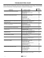
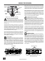
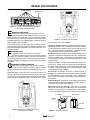
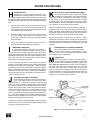
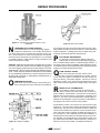
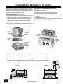
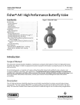
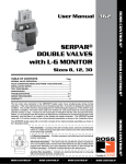
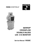
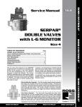
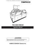
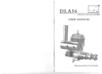
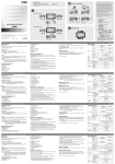
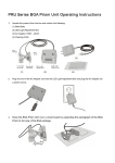
ROSS CONTROLS
®
Cylinder
4 2
2
Flow
Control
Valves
14
12
1
5 13
Sol C
C1
C2
P Holding
Pressure
V1
Sol A
V2
Sol B
L-O-Xfi
Valve
VALVE INSTALLATION
& SERVICE MANUAL
Manual 331G
TABLE OF CONTENTS
Page
DOUBLE VALVES- FOR PRESS CONTROL: Service manuals available from ROSS
ADDITIONAL AVAILABLE SERVICE INFORMATION ............................................................. 3
INSTALLATION NOTES ........................................................................................................... 4
MAINTENANCE ..................................................................................................................... 4-5
TROUBLESHOOTING ........................................................................................................... 5-6
REPAIR PROCEDURES ...................................................................................................... 7-10
CONVERSION TO EXTERNAL PILOT SUPPLY ..................................................................... 11
WARRANTY ............................................................................................................................ 12
ADDITIONAL SERVICE
INFORMATION AVAILABLE
The installation, maintenance, and troubleshooting information in this Service Manual is intended primarily for use with
ROSS single-element poppet and spool valves. Similar
information on double valves for press controls is covered in
separate service manuals available from ROSS.
This Service Manual should be a useful guide to solving the
problems most likely to be encountered in a pneumatic
system. Other valuable guides are the Plate Drawings,
Instruction Sheets included in Service Kits, and reference
pages from the Master Catalog for the particular valve being
serviced. A Plate Drawing is a ROSS information sheet giving the numbers of repair parts for particular valve models.
An Instruction Sheet details the valve installation and service processes. The Master Catalog pages offer model
dimensions and standard specification information.
Most parts are made available in the form of service kits
which contain all the parts normally required for specific
service operations. A Valve Body Service Kit for a poppet
valve, for example, includes the seals, poppets, springs, and
gaskets required to service the valve body assembly.
For copies of these publications or other product data, call
ROSS or your ROSS Distributor.
www.rosscontrols.com
3
INSTALLATION
Pneumatic equipment should be installed only by persons
trained and experienced in the installation of such equipment.
or solenoid burnout. If electrical power is supplied by a separate transformer, it must be capable of handling the inrush
current of the solenoids without significant voltage drop.
Air lines: Before installing a valve in an existing system,
the air lines must be blown clean of all contaminants which
may be in the system. It is recommended that a 5-micron
air filter be installed in the inlet line close to the valve.
Operating Pressures and Temperatures: Maximum and
minimum operating pressures and temperatures are specified for each type of valve. Staying within these limits contributes to longer valve life and proper operation. If you must
exceed these limits, consult ROSS for advice on such service.
Valve Inlet: DO NOT RESTRICT AIR SUPPLY. Any restriction of the air supply lines (for example, sharp bends or
clogged filter element) will reduce the speed with which the
outlet volume is pressurized, and can also cause the valve
to malfunction.
Valve Outlet(s): For faster pressurizing and exhausting of
the outlet volume, locate the valve as close as possible to
the mechanism being operated. Also, any restriction in the
outlet lines (for example, sharp bends or undersize lines)
will reduce both pressurizing and exhausting speeds.
Valve Exhaust(s): DO NOT RESTRICT EXHAUST OF
POPPET VALVES as this can cause the valve to malfunction. To reduce exhaust noise, use a silencer such as the
ROSS Muffl-Air®.
Electrical Conduit Port: It is important that the electrical
supply be of the correct voltage and Hertz. ROSS solenoids are rated for continuous duty at 85% to 110% of the
voltage shown on the solenoid coil. Multi-rated solenoids
(e.g., 110-120 volts) are rated for continuous duty at 85% to
110% of the maximum voltage shown. A supply voltage that
does not fall within this range can lead to faulty valve action
Pilot Pressure: For proper operation, pilot pressure must
not fall below the minimum specified for the valve. For poppet valves, pilot pressure must be at least equal to the main
supply pressure.
If a solenoid piloted valve must operate at a pressure lower
than the minimum specified pilot pressure, an external pilot
supply of adequate pressure must be used. Some ROSS
valves automatically accept an external pilot supply, while
others must be converted to such use as explained on page
11.
Vacuum or Non-Air Service: Many ROSS valves can be
used for vacuum service or with fluids other than air. Such
applications require an external pilot supply. For more information, consult ROSS for Bulletin 440 (“ROSS Valves for
Vacuum Service”).
Pipe Installation: To install pipe in valve ports, engage pipe
one turn, apply pipe thread sealant (tape not recommended),
and tighten pipe. This procedure will prevent sealant from
entering and contaminating the valve.
MAINTENANCE
Pneumatic equipment should be maintained only by persons trained and experienced in the maintenance of such
equipment.
Supply Clean Air. Foreign material lodging in valves is a
major cause of improper operation. The use of a 5-micronrated air filter located close to the valve is strongly recommended. The filter bowl should be drained regularly, and if
its location makes draining difficult, the filter should be
equipped with an automatic drain.
Check Lubricator Supply Rate. A lubricator should put a
fine oil mist into the air line in direct proportion to the rate of
air flow. Excessive lubrication can cause puddling in the valve
and lead to malfunctions. For most applications an oil flow
rate in the lubricator of one drop per minute is adequate.
4
(Note that the valve does not itself require air line lubrication.) See below for information about lubricants that are
compatible with the materials used in the valve and are suitable for use in compressed air systems.
Compatible Lubricants. Although most ROSS valves do
not require air line lubrication, they may be used with lubricated air being supplied to other mechanisms. Some oils
contain additives that can harm seals or other valve components and so cause the valve to malfunction. The best oils
to use are those specifically compounded for air line service. These are generally petroleum base oils with oxidation inhibitors, an aniline point between 180°F (82°C) and
220°F (104°C), and an ISO 32 or lighter viscosity. See chart
on next page.
ROSS CONTROLS®
COMPATIBLE LUBRICANTS
MAKER
BRAND NAME
Amoco .......................... American Industrial Oil 32
Amoco Spindle Oil C
Amolite 32
Citgo ............................. Pacemaker 32
Exxon ........................... Spinesstic 22
Teresstic 32
Mobil ............................ Velocite 10
Non-Fluid Oil ................ Air Lube 10H/NR
Shell ............................. Turbo T32
Sun ............................... Sunvis 11
Sunvis 722
Texaco .......................... Regal R & O 32
Union ............................ Union Turbine Oil
Cleaning the Valve. If the air supplied to the valve has not
been well filtered, the interior of the valve may accumulate
dirt and varnish which can affect the valve’s performance.
Although ROSS poppet valves are very tolerant of dirty air,
the valve may sometimes need cleaning. To clean the valve
use any good commercial solvent or kerosene. Do not use a
chlorinated solvent or abrasive materials. The former damages seals, and abrasives can do permanent damage to
metal parts. Reassemble the valve with a gasket and seal
kit available from ROSS. Lubricate all sliding surfaces with
the grease provided in the gasket and seal kit.
Electrical Contacts. In the electrical circuits associated with
the valve solenoids, keep all switches or relay contacts in
good condition to avoid solenoid malfunctions.
Replace Worn Components. In most cases it is not necessary to remove the valve from its installation for servicing.
However, turn off the electrical power to the valve, shut off
the air supply, and exhaust the air in the system before beginning any disassembly operation. Follow appropriate lockout/tag-out procedures.
TROUBLESHOOTING
Troubleshooting is the process of looking at a valve’s symptoms (e.g., blowing to exhaust or buzzing solenoid), and then
relating these symptoms to their most likely causes. By carefully analyzing the problem, the experienced troubleshooter
can quickly isolate the trouble, and take appropriate corrective steps.
To assist in the troubleshooting process, the Troubleshooting Chart on page 5 lists most of the common symptoms
which valves exhibit, and their probable causes.
Before disassembling a valve to investigate a system malfunction, check other possible causes of the malfunction.
Because malfunctions in other components can affect valve
action, the valve is sometimes blamed for a problem which,
in fact, lies elsewhere. We suggest, therefore, that potential
malfunctions in all system components be considered when
trouble occurs. Leaky cylinder packings, poor electrical contacts, dirty filters, and air line leaks or restrictions are just a
few of the things to be considered when troubleshooting a
pneumatic system. Consideration of these possibilities can
sometimes save an unnecessary valve disassembly job.
Caution: Before disassembling a valve or other pneumatic component
or removing it from its installation, shut off and exhaust the entire pneumatic circuit, and verify that any electrical supply is turned off. Follow
appropriate lock-out/tag-out procedures.
www.rosscontrols.com
5
TROUBLESHOOTING CHART
When the valve fails to operate properly, check for the Symptoms listed below in the first column. For each Symptom,
several Possible Causes are listed in the second column. For each Possible Cause, there is a Repair Procedure identified
by a letter in the last column. These Repair Procedures are detailed in the following pages.
SYMPTOMS
POSSIBLE CAUSES
REPAIR
PROCEDURE
Valve Blows to Exhaust When Not Actuated
Inlet Poppet Not Sealing ......................................
Damaged Seals ...................................................
Damaged Valve-to-Base Gasket .........................
Cylinder Leaks ....................................................
A
B
D
H
Valve Blows to Exhaust When Actuated
Damaged Valve-to-Base Gasket .........................
Damaged Seals ...................................................
Damaged Spool ..................................................
Cylinder Leaks ....................................................
Inadequate Air Supply .........................................
Water or Oil Contamination .................................
D
B
F
H
I
R
Solenoid Fails to Actuate Valve But Manual Override
Does Actuate Valve
Loose Pilot Cover or Faulty Solenoid ..................
Inadequate Voltage at Solenoid ..........................
G
J
Solenoid Fails to Actuate Valve and Manual Override
Also Fails to Actuate Valve
Damaged Seals ...................................................
Varnish Deposits in Valve ....................................
Inadequate Pilot Pressure ...................................
Water or Oil Contamination .................................
B
C
L
R
Air Flow is Normal Only in Actuated Position
Broken Return Spring ..........................................
E
Solenoid Buzzes
Damaged Solenoid ..............................................
Inadequate Voltage at Solenoid ..........................
Varnish in Direct Operated Spool Valve ...............
G
J
C
Solenoid Burns Out
Varnish in Direct Operated Spool Valve ...............
Incorrect Voltage at Solenoid ..............................
C
J
Pilot Section Blows to Exhaust
Loose Pilot Cover ................................................
Pilot Poppet Not Sealing .....................................
G
K
Poppet Chatters
Inadequate Air Supply .........................................
Inadequate Pilot or Signal Pressure ....................
Damaged Silencer ...............................................
I
L
N
Valve Action is Sluggish
Damaged Seals on Spool Valve ..........................
Varnish in Spool Valve .........................................
Inadequate Air Supply .........................................
Inadequate Pilot or Signal Pressure ....................
Inadequate Lubrication ........................................
Damaged Silencer ...............................................
Water or Oil Contamination .................................
B
C
I
L
M
N
R
Sequence Valve Gives Erratic Timing
Damaged Piston Seal ..........................................
Excessive Lubrication ..........................................
Fluctuating Air Pressure ......................................
Accumulated Water .............................................
Damaged Gasket ................................................
O
M
P
R
D
Flow Control Valve Does Not Respond to Adjustment
Excessive Lubrication ..........................................
Incorrect Installation or Dirt in Valve ....................
M
Q
6
ROSS CONTROLS®
REPAIR PROCEDURES
PISTON
EXHAUST
POPPET
RESILIENT
FACE
VALVE
SEATS
INLET
POPPET
RETURN
SPRING
GUIDED STEM
Figure 3- Typical Inline Poppet Valve Body
A
MAIN INLET POPPET NOT SEALING
Foreign particles may be holding the poppet off its seat.
Taking appropriate safety precautions, cycle the valve several times to see if the flow of air through the valve will flush the
particles out. If not, it will be necessary to disassemble the valve.
See figure 3 or 4.
Follow appropriate lock-out/tag-out procedures. Turn off the electrical power to the valve. Shut off the air supply and exhaust the air
in the system. Disassemble the valve body assembly. Inspect the
inlet poppet for evidence of dirt particles or damage to the poppet.
Clean or replace poppet as required. If the poppet is swollen or
has deteriorated, improper lubricants or solvents may be the cause.
Use only compatible lubricants; see page 5.
Also check the poppet seat(s) for dirt and damage. If there is damage to a seat, the entire valve body assembly must be replaced. If
there is no damage to poppet or seat(s), inspect other parts of
valve for damage. If there is no other damage, clean thoroughly,
lubricate lightly, and reassemble.
B
FAULTY SEALS
The materials of which seals are made can be attacked
by substances such as chlorinated hydrocarbons (trichloroethylene, for example) and some lubricating oils. This can produce swelling or shrinking of the seals and result in erratic valve
action or blowing to exhaust. Swollen seals may cause poppet
valves to stick in a partially open position so that the valve blows to
exhaust. See Figure 3 and 4. Swollen seals on a spool valve (see
Figure 5) can result in sluggish or erratic valve action, or even failure of the spool to move at all.
Badly nicked or torn seals can produce blowing to exhaust in valves
by allowing air to pass from one port area to another. Small leaks
in piston poppet seals can affect the timing accuracy of sequence
adaptors on inline valves, or even render the valve inoperable.
Before disassembling the valve to inspect the seals, turn off the
electrical power to the valve, shut off the air supply, and exhaust
the air in the system. Follow appropriate lock-out/tag-out procedures. Inspect the seals and replace any that are defective. Lubricate the seals lightly and reassemble the valve. To insure long
seal life, be sure to use only compatible lubricant in the pneumatic
system. For a list of such lubricants, see page 5.
C
VARNISH DEPOSITS IN VALVE
See Figures 3, 5 or 6. Varnish deposits can cause a
valve to act sluggishly or even prevent movement of the
valve element altogether, especially after a period of inactivity. A
spool valve frozen in position by varnish can cause a direct acting
solenoid to buzz, and eventually lead to solenoid burnout. Varnish
results from the action of oxygen on the lubricating oil, and can be
aggravated by excess heat. Varnish can also come from overheated compressor oil carried over into the air lines. Properly lubricated valves do not usually suffer from varnish deposits.
To remove varnish, use a water soluble detergent or solvent such
as kerosene. Do not scrape varnish off. Also, avoid chlorinated
solvents (trichloroethylene, for example) and abrasive materials.
The former can damage seals and poppets, and abrasives can do
permanent damage to metal parts. After cleaning, lightly lubricate
moving valve parts and reassemble. See compatible lubricant chart
on page 5.
D
DAMAGED GASKETS
A broken or scored web on a valve-to-base gasket can
produce air leakage between ports. This can result in
unwanted pressurizing of an outlet port or blowing to exhaust. –A
leaking gasket on an inline valve can also produce operating problems, but is apt to be most noticeable on valves with timed sequence adaptors. If the gasket between adaptor and valve body
leaks, it can bleed off the air which is slowly pressurizing the piston, so that the timing can be seriously affected. Damage to a
gasket is most likely to occur during assembly. Rarely does a gasket become defective during normal operation. Do not attempt to
“make do” with a damaged gasket. It will give trouble sooner or
later. Replace it.
RESILIENT SEALS
VALVE SEATS
INLET POPPET
Figure 4- Poppet Valve Body for Base Mounting
Figure 5- Resilient Seal Aluminum Spool Valve
Body for Base Mounting
www.rosscontrols.com
7
REPAIR PROCEDURES
Varnish Deposits
Return Spring
Figure 6- Precision Finished Stainless Steel Spool
Valve Body for Base Mounting
E
BROKEN RETURN SPRING
A broken return spring on a spool valve (see Figure 6) can
cause the spool to remain in an actuated position, or to be only
partially returned. In the latter case, several abnormal flow patterns
may result depending on the valve configuration. If a spool valve has a
normal flow pattern only in an actuated position, a broken return spring
is the most likely cause of the trouble.
A broken return spring on an inline poppet valve is less likely to prevent
closing of the inlet poppet, but should be considered as a possible cause
of the valve’s blowing to exhaust when not actuated, especially in a low
pressure application.
F
DAMAGED SPOOL
If a spool is badly scored or nicked, it can allow air to
pass from one port area to another. This can result in unwanted
pressurizing of an outlet port or blowing to exhaust. The problem can
be further aggravated by the spool’s cutting the resilient seals and increasing the leakage. A damaged spool cannot be repaired, but must
be replaced.
Figure 7- Pilot Section for Inline Valves
the cover and check for normal operation.
Improperly installed solenoid- If a solenoid is cocked out of line during assembly (perhaps when a replacement solenoid was installed),
the pilot poppet may be held off its seat so that the valve will not function. Check solenoid for burnout (see below). If solenoid passes this
check, reassemble carefully to eliminate misalignment.
Burned out solenoid- Check the coil for electrical continuity with an
ohmmeter, and replace the solenoid if the coil is open. In spool valves
with direct solenoid control, varnish deposits may prevent spool motion. This will prevent full motion of the solenoid plunger, and can cause
solenoid burnout.
G
Solenoids operated in too high an ambient temperature are also subject to burnout. However, the most common cause of solenoid burnout
is improper supply voltage. See Incorrect Voltage at Solenoid, Repair
Procedure J. If the Solenoid coil is not burned out, examine the solenoid for the following three conditions:
Loose pilot cover- A loose pilot cover can give the symptoms of a
defective solenoid because it prevents full travel of the pilot valve. However, the valve can operate properly if manual actuation is used. This is
because the gap is closed by the pressure of manual actuation. Tighten
Dirt under the “T” plunger- See Figure 9. Before removing “T”
plunger, mark it and the frame so that they can be reassembled with
the same orientation. Remove “T” plunger. Clean “T” plunger and
frame. Before reassembling, inspect shading coil and air gap as explained below.
DAMAGED SOLENOID OPERATION
Verify that the supply voltage is correct. Refer to Incorrect
Voltage at Solenoid, Repair Procedure J. With the electrical
supply to the solenoid shut off, check for the following: (See Figure 7 or
8).
Broken shading coil- See Figure 9. Copper shading coils reduce the
solenoid’s tendency to buzz when operated on alternating current. If a
coil is broken, the solenoid must be replaced.
Wear that causes a loss of air gap- There must be a small gap
between the solenoid plunger and field frame when the solenoid is
energized. See air gap, Figure 9. If significant wear is apparent under
“T” section, the air gap can be lost and the solenoid must be replaced.
“T” PLUNGER
WEAR AREAS
POSSIBLE DIRT
SHADING
COIL
AIR GAP
Figure 8- Pilot Section for ANSI valves, size
2.5-20 with Plug-in Bases
8
FIELD FRAME
Figure 9- Typical Pilot Solenoid
ROSS CONTROLS®
REPAIR PROCEDURES
H
CYLINDER LEAKS
See figure 10. Four-way valves sometimes blow to exhaust because of leaking packings in the work cylinder
connected to the valve. Before looking for faults in the valve, check
the cylinder for leaks. In the following steps, take appropriate safety
precautions because both the valve and the cylinder will be actuated.
1.
2.
3.
Disconnect the air line to the end of the cylinder which is not
under pressure. If air comes out of the open cylinder port, the
cylinder packings are leaking and must be repaired. If there
is no leakage, reconnect the air line.
Reverse the position of the valve and disconnect the other air
line to the cylinder. Again check for air coming out of the
cylinder port. If there is air coming out, the cylinder packings
must be repaired.
If there is no leakage at the cylinder, reconnect the air line
and proceed with troubleshooting the valve itself.
I
INADEQUATE AIR SUPPLY
An inadequate air supply volume causes an excessive
pressure drop during valve actuation. Pilot air pressure
may be great enough to begin movement of the valve element,
but the pressure drop resulting from the filling of the outlet volume
depletes the pilot air supply. This may result in chattering or oscillating of the main valve, or may simply keep the main valve partially actuated so that it blows to exhaust.
Check the pressure drop shown on the gauge at the pressure
regulator. If the pressure falls more than 10% during actuation of
the valve, the air supply may be inadequate. Inspect the system
for undersize supply lines, sharp bends in the piping, restrictive
fittings, a clogged filter element, or a defective pressure regulator.
Remember, too, that the air volume supplied can be insufficient if
more pneumatic devices are connected to a circuit than the compressor is designed to serve.
K
PILOT SECTION - DIRTY OR DAMAGED INSERT
Turn off electrical power to valve. Shut off the air supply
and exhaust air in the system. Follow appropriate lockout/tag-out procedures. Disassemble the pilot section. For pilots
shown in Figure 7 or 8, remove pilot insert. Check action of insert
by pressing lightly on the spring protruding from the top. Throughout its travel (about 1/32 inch) it should move easily without jerking or grabbing. If not, the insert must be replaced.
Inspect the poppet and seats for foreign particles or damage. If
the poppet or upper seat is damaged, the pilot insert must be replaced. If the lower seat is damaged, the entire pilot housing must
be replaced. Before installing a new insert, blow out the pilot air
passages to remove any loose dirt particles. Reassemble.
For ISO valves and size 1.5 ANSI valves, see Figure 11. Disassemble pilot to remove the plunger. Inspect seals on both ends of
the plunger as well as the seats against which they seal. Anything
damaged should be remedied only by replacing the entire pilot
assembly.
L
INADEQUATE PILOT OR SIGNAL PRESSURE
Pilot or signal pressure below the minimum requirement can produce chattering, valve oscillation, or sluggish valve action. Check your valve specifications for minimum
pilot or signal pressure requirements.
M
LUBRICATION
Some valves require lubrication to operate properly.
Check the system lubricator to see that it is working as it
should. Also check list of compatible lubricants on page 5. DO
NOT LUBRICATE EXCESSIVELY. Excess oil can accumulate in
low points of the system and restrict the flow of air. It can also
form pools which will produce a dashpot effect and slow valve
action. A visible oil fog exhausting from the valve is a sure sign of
excessive lubrication. Properly lubricated parts should have only
a thin film on them. For most applications, an oil flow rate in the
lubricator of one drop per minute is adequate.
J
INCORRECT VOLTAGE AT SOLENOID
ROSS solenoids are rated for continuous duty at 85% to
110% of the voltage shown on the solenoid coil. Multirated solenoids (e.g., 110-120 volts) are rated for continuous duty
at 85% to 110% of the maximum voltage shown on the solenoid
coil. A supply voltage that does not fall within this range can result
in failure of the valve to shift or lead to solenoid burnout. Before
checking the electrical supply, shut off and exhaust the air supply
to the valve. Attach a voltmeter to the electrical supply to the
solenoid. Actuate the solenoid and read the voltage during actuation. If the voltage falls below the allowable operating range, the
electrical supply is inadequate, even though the supply voltage
might be correct without the electrical load.
A voltage that exceeds the allowable operating range can result in
solenoid burnout, or can cause impact damage resulting in a loss
of air gap. See Repair Procedure G.
Figure 10- Cylinder Operated by Four-Way Valve
www.rosscontrols.com
9
REPAIR PROCEDURES
Figure 11- Pilot Section of Valves for Size 1.5 and
ISO Bases
Figure 12- Flow Control Valve
N
UNDERSIZE OR PLUGGED SILENCER
An undersize silencer, or one that is partially plugged,
restricts the exhaust flow. The resulting back pressure
can cause erratic motion of poppet valve elements and/or cylinders. Remove silencer to see if valve performance is improved.
Clean silencer and verify that it is of adequate size. Do not reinstall
an undersize silencer. Install cleaned or larger size silencer and
check valve performance again.
CAUTION: Restricting the exhaust port of a poppet valve can cause
the valve to malfunction. Silencers must be resistant to clogging and
have a flow capacity greater than the exhaust capacity of the valve.
ROSS Muffl-Air® silencers of the proper pipe size fulfill these requirements. ROSS expressly disclaims all warranties and responsibility
for any unsatisfactory performance or injuries caused by the use of
the wrong type, wrong size, or inadequately maintained silencer installed with a ROSS valve.
O
DAMAGED PISTON SEAL
Piston seals may be either O-rings or the lip seal type. If
worn or damaged, the seal can allow pilot or signal pres-
sure to leak by the piston and cause erratic valve response. Operating problems are apt to be most noticeable on valves with timed
sequence adaptors. A leaking piston seal can bleed off the pressurizing air and seriously affect the timing function.
P
FLUCTUATING AIR PRESSURE
If a valve with a timed sequence adaptor suffers from
erratic timing, the cause can be a fluctuating supply pressure. Consistent timing requires a consistent supply pressure. If
the supply pressure varies considerably, install a pressure regulator set at the system’s lowest expected pressure and reset the timed
sequencer to provide the desired time delay.
Q
FLOW CONTROL VALVES
Flow control valves are most often used to control
the flow of air as it is exhausting from a cylinder. The flow
control valve’s flow pattern is indicated on the valve body by an
arrow, and also by a fluid power diagram. Check to be sure the
installation is correct. If it is, check for foreign material in the valve
which could prevent the poppet from seating properly. See Figure
12.
R
WATER OR OIL CONTAMINATION
Accumulations of water or oil have an especially bad
effect on devices with small orifices such as timed sequence adaptors. Accumulation in such a device can change the
effective size of the time orifice, or even block it completely. See
Figure 13. The device must be disassembled, cleaned, lightly lubricated, and reassembled. It may be necessary to install a filter in
the supply line to prevent recurrence of the problem.
Figure 13- Sequence Adaptor
10
Accumulations of water or oil can also occur at low points in pilot
supply lines. This can result in pressure fluctuations that produce
erratic timing. The best cure is to eliminate low points. Water and
oil can also accumulate at low points in a valve, and hinder movement of the valve element, perhaps completely preventing its motion. See Figure 3. This is especially true of a valve operating in a
subfreezing environment where accumulated water can turn to ice.
It is important in such applications to ensure that the supply air is
dry, and that the air line filter is drained frequently. If there is evidence of excess oil accumulation, see Repair Procedure M.
ROSS CONTROLS®
CONVERSION TO EXTERNAL PILOT SUPPLY
When a valve is converted to external pilot supply, consult
ROSS for the converted valve’s model number. This will
allow records and drawings to be changed and prevent errors when ordering future replacements.
INLINE POPPET VALVES: See Figure 1.
1. Remove pilot section and adaptor plate from valve body.
2. Remove pipe plug from external pilot supply port, and
reinstall the plug in the internal pilot supply passage.
3. Replace pilot section.
4. Attach 1/8” pilot supply line to external plot supply
port (X-1).
5. External pilot supply pressure must be at least equal to
the main supply pressure.
PILOT
EXHAUST
PORT
ANSI SIZE 4, 10, 20 BASE MOUNTED VALVES:
See Figure 2.
1. Remove valve from base.
2. Remove pipe plug from underside of valve body.
3. Install pipe plug in internal pilot supply passage.
4. Attach 1/8” pilot supply line to external pilot supply port
X in base.
5. Replace valve on base.
6. For poppet valves, external pilot supply pressure must be
at least equal to the main supply pressure.
EXTERNAL
PILOT
SUPPLY
PORT
ADAPTO R
PLATE
INTERNAL
PILOT
SUPPLY
PASSAGE
Figure 1
Figure 2
ISO SIZES 1, 2, & 3 and ANSI SIZES 1.5 & 2.5
Base-mounted valves: See Figures 3 and 4.
1. Remove plug from port 14 (port 12 on ANSI 1.5 & 2.5).
2. Pipe 1/8” supply line to port 14.
3. Pressure in external supply line should be greater than inlet. If, for any reason, the external
supply is lst or drops below inlet pressure, the valve will switch back to internal pilot supply.
Figure 3
Figure 4
www.rosscontrols.com
11
ROSS CONTROLS®
P.O. Box 7015
Troy, Michigan 48007 U.S.A.
Telephone (00) 1-248-764-1800
Fax (00) 1-248-764-1850
www.rosscontrols.com
In the United States:
Customer Service: 1-800-GET-ROSS
Technical Service: 1-800-TEK-ROSS
ROSS/FLEX® Service: 1-888-ROSS-FLX
ROSS EUROPA GmbH
ROSS UK Ltd.
St. James Road, Brackley
Northamptonshire NN13 7XY
United Kingdom
Telephone (011) 44-1280-706668
Fax (011) 44-1280-705630
βe 2
Robert-Bosch-Straβ
D-63225 Langen, Germany
Telephone (011) 49-6103-7597-0
Fax (011) 49-6103-7469-4
ROSS ASIA K.K.
10209-5 Tana, Sagamihara-shi
Kanagawa 229-1124, Japan
Telephone (011) 81-427-78-7251
Fax (011) 81-427-78-7256
ROSS SOUTH AMERICA Ltda.
Rua Olavo Gonçalves, 43
Centro- São Bernardo Do Campo
São Paulo, Brazil CEP 09725-020
Telephone (011) 55-11-9122-2705
ROSS ASIA K.K.CHINA LIAISON OFFICE
ROSS CONTROLS INDIA Pvt. Ltd.
Room 17B, FuHai Building,
288 Huanghe Road
Shanghai, China
Telephone (011) 21-6372-2579
Fax (011) 21-6372-2505
‘B’ Mount Chambers, Fourth Floor
758 Mount Road
Chennai, 600 002 India
Telephone (011) 91-44-841-3136
Fax (011) 91-44-841-3137
Warranty
Products manufactured by ROSS are warranted to be free of defects in material and workmanship for a period of one year from the
date of purchase. ROSS’ obligation under this warranty is limited to repair or replacement of the product or refund of the purchase
price paid solely at the discretion of ROSS and provided such product is returned to ROSS freight prepaid and upon examination by
ROSS is found to be defective. This warranty shall be void in the event that product has been subject to misuse, misapplication, improper
maintenance, modification or tampering. THE WARRANTY EXPRESSED ABOVE IS IN LIEU OF AND EXCLUSIVE OF ALL OTHER
WARRANTIES AND ROSS EXPRESSLY DISCLAIMS ALL OTHER WARRANTIES EITHER EXPRESSED OR IMPLIED WITH
RESPECT TO MERCHANTABILITY OR FITNESS FOR A PARTICULAR PURPOSE. ROSS MAKES NO WARRANTY WITH RESPECT
TO ITS PRODUCTS MEETING THE PROVISIONS OF ANY GOVERNMENTAL OCCUPATIONAL SAFETY AND/OR HEALTH LAWS
OR REGULATIONS. IN NO EVENT SHALL ROSS BE LIABLE TO PURCHASER, USER, THEIR EMPLOYEES OR OTHERS FOR
INCIDENTAL OR CONSEQUENTIAL DAMAGES WHICH MAY RESULT FROM A BREACH OF THE WARRANTY DESCRIBED
ABOVE OR THE USE OR MISUSE OF THE PRODUCTS. NO STATEMENT OF ANY REPRESENTATIVE OR EMPLOYEE OF ROSS
SHALL EXTEND THE LIABILITY OF ROSS AS SET FORTH HEREIN.
Printed in the U.S.A- 5/98
© Copyright 1998, ROSS CONTROLSTM
Form A10018