1
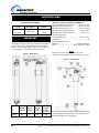
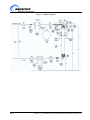
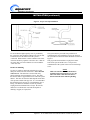
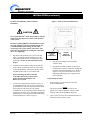
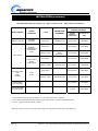
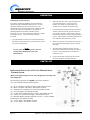
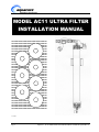
MODEL AC11 ULTRA FILTER
INSTALLATION MANUAL
OOOOOOOOOOOOOOOOOOOOOOOOOOOO
OOOOOOOOOOOOOOOOOOOOOOOOOOOO
OOOOOOOOOOOOOOOOOOOOOOOOOOOO
OOOOOOOOOOOOOOOOOOOOOOOOOOOO
OOOOOOOOOOOOOOOOOOOOOOOOOOOO
OOOOOOOOOOOOOOOOOOOOOOOOOOOO
OOOOOOOOOOOOOOOOOOOOOOOOOOOO
OOOOOOOOOOOOOOOOOOOOOOOOOOOO
OOOOOOOOOOOOOOOOOOOOOOOOOOOO
OOOOOOOOOOOOOOOOOOOOOOOOOOOO
OOOOOOOOOOOOOOOOOOOOOOOOOOOO
OOOOOOOOOOOOOOOOOOOOOOOOOOOO
OOOOOOOOOOOOOOOOOOOOOOOOOOOO
OOOOOOOOOOOOOOOOOOOOOOOOOOOO
OOOOOOOOOOOOOOOOOOOOOOOOOOOO
OOOOOOOOOOOOOOOOOOOOOOOOOOOO
OOOOOOOOOOOOOOOOOOOOOOOOOOOO
OOOOOOOOOOOOOOOOOOOOOOOOOOOO
OOOOOOOOOOOOOOOOOOOOOOOOOOOO
OOOOOOOOOOOOOOOOOOOOOOOOOOOO
OOOOOOOOOOOOOOOOOOOOOOOOOOOO
OOOOOOOOOOOOOOOOOOOOOOOOOOOO
OOOOOOOOOOOOOOOOOOOOOOOOOOOO
OOOOOOOOOOOOOOOOOOOOOOOOOOOO
OOOOOOOOOOOOOOOOOOOOOOOOOOOO
OOOOOOOOOOOOOOOOOOOOOOOOOOOO
OOOOOOOOOOOOOOOOOOOOOOOOOOOO
OOOOOOOOOOOOOOOOOOOOOOOOOOOO
OOOOOOOOOOOOOOOOOOOOOOOOOOOO
OOOOOOOOOOOOOOOOOOOOOOOOOOOO
OOOOOOOOOOOOOOOOOOOOOOOOOOOO
OOOOOOOOOOOOOOOOOOOOOOOOOOOO
OOOOOOOOOOOOOOOOOOOOOOOOOOOO
OOOOOOOOOOOOOOOOOOOOOOOOOOOO
OOOOOOOOOOOOOOOOOOOOOOOOOOOO
OOOOOOOOOOOOOOOOOOOOOOOOOOOO
73-1024
Pg. 1
Aquacore® AC11 Whole Home Ultra Filtration Water Treatment System Rev.A
TABLE OF CONTENTS
General Information ..................................................2
General.................................................................2
Warranty Information ..........................................2
Service/Technical Information.............................2
Important Safety Information ...................................3
Specifications...............................................................4
Power Transformer ..............................................4
Specifications (Filter Cartridge)...........................4
Dimensions ..........................................................4
Components .........................................................4
Recommended Installation & Components List ......5
System Schematic Diagram .......................................6
Installation...................................................................7
Unpacking ............................................................7
Equipment Setup..................................................7
General.................................................................7
Electrical ..............................................................7
Plumbing ..............................................................7
Suggested Tools & Supplies for Installation........8
Locating & Mounting the System ........................8
Inlet Water Plumbing ...........................................8
Drain Line Plumbing............................................9
Permeate Line Plumbing, Meter/Controller
Installation..........................................................10
Programming the Meter .....................................10
Operation...................................................................13
Sanitizing the System and Lines ........................13
Parts List ...................................................................13
Troubleshooting ........................................................14
Warranty ...................................................................15
GENERAL INFORMATION
GENERAL
WARRANTY INFORMATION
This manual provides the safety and installation
procedures for the Aquacore® AC11 Whole Home Ultra
Filtration Water Treatment System. It is recommended
that all information contained in this manual be read
prior to installing the system.
Please read the full text of the Warranty on the last page
of this manual.
The Aquacore® AC11 Whole Home Ultra Filtration
Water Treatment System reduces bacteria, cysts,
precipitated iron, colloidal clay and algae, and provides
a reduction of viruses that may be present in a typical
water supply, thereby providing maximum water
quality for whole house applications.
.
If the system arrives damaged, contact the carrier
immediately and file a damage claim. Save all packing
materials when filing a claim. Freight damage claims
are the responsibility of the purchaser and are not
covered under the Warranty.
SERVICE/TECHNICAL ASSISTANCE
If you experience any problems with the installation of
the system, contact your local distributor for assistance
DISCLAIMER
The Aquacore® AC11 is not designed to be used in pharmaceutical
or medical applications where pyrogen and endotoxin free water is necessary.
CAUTION
DO NOT OVERTIGHTEN CONNECTIONS OR THEY MAY SPLIT. Tighten 1-2 turns beyond finger tight. It is
recommended that plastic fittings be used when connecting to the system’s plastic connections. This will reduce the
possibility of cracking the connections due to over-tightening.
Pg. 2
Aquacore® AC11 Whole Home Ultra Filtration Water Treatment System Rev.A
IMPORTANT SAFETY INFORMATION
Throughout this manual, the following safety words and
symbols signify important safety issues with regard to
installing and maintaining the system.
The system should be grounded according to
local electrical codes to prevent the possibility of
electrical shock.
All electrical connections must be in accordance
with local electrical codes and any other
applicable laws and regulations.
CAUTION
GENERAL CAUTION. Indicates information
important for the proper operation of the
system. Failure to observe may result in
damage to the system component(s).
In addition to the warnings and cautions in this manual,
use the following guidelines for safe installation of the
system.
Read all instructions before installing the system.
For your safety, the system is furnished with a
low voltage power transformer to plug into the
household electrical outlet. Do not replace this
transformer with another power supply as this
may cause damage to the electronics.
Install or locate the system only for its intended
use as described in this manual. Do not use
corrosive chemicals in this system.
Do not install this system if it has a damaged
cord or plug, if it is not working properly or if it
has been damage or dropped.
WARNING-ELECTRICAL SHOCK
HAZARD. Failure to follow the following
instructions could result in serious injury:
o
Do not modify the power supply cord. If it
does not fit the outlet, have a suitable outlet
installed by a qualified electrician.
o
Do not use an extension cord with this
system.
o
Check with a qualified electrician if in doubt
as to whether the system is properly
grounded. If the plumbing is used as an
electrical ground, installation of this system
may interrupt this ground and a jumper wire
around the unit may be required.
If the power supply cord is damaged, it must be
replaced by the manufacturer or its service agent,
or a similarly qualified person.
Keep the cord away from heated surfaces.
This system is to be installed in compliance with
the local plumbing code and any other applicable
laws and regulations.
Turn the system off and disconnect from the
power source before performing any service or
maintenance on the system.
Water pressure must not exceed 72 psi (4.96
bar). To reduce the water pressure, install a water
pressure regulator and set to 50 psi (3.45 bar).
This system is not intended to filter or to be in
contact with any solvents.
Protect from insecticides.
Do not immerse the cord or plug in water.
Protect from water hammer and freezing.
If painting is necessary use only water based
latex paint.
Pg. 3
Aquacore® AC11 Whole Home Ultra Filtration Water Treatment System Rev.A
SPECIFICATIONS
POWER TRANSFORMER
Input
Description
Output
120 VAC
50/60 Hertz
Power
Transformer
12 VDC
1 Amp
IMPORTANT
The right is reserved to change specifications and product
design without notice. Such revisions do not entitle the
buyer to corresponding changes, improvements, additions,
or replacements for a previously purchased system.
Figure 1. Dimensions
SPECIFICATIONS (FILTER CARTRIDGE)
Recommended Operating Pressure.........50 psi (3.45 bar)
Maximum Operating Pressure ................72 psi (4.96 bar)
Minimum Operating Pressure ................30 psi (2.07 bar)
Maximum Operating Temperature ..............104°F (40°C)
Minimum Operating Temperature ..................40°F ( 4°C)
Maximum Operating
Differential Pressure ................................. 45 psi (3.1 bar)
pH Range ...................................................................3-10
Molecular Weight Cut-Off
(MWCO)............................................150 kD (kilodalton)
Flow .......................................... Max. 10 gpm (45.5 lpm)
NOTE
If pressure exceeds 72 psi (4.96 bar), a pressure
regulator should be installed and set for 50 psi (3.45 bar).
Figure 2. Components
Unit
AC11
Pg. 4
A
Width
(inches)
B
Depth
(inches)
C
Height
(inches)
21
8
51
Operating
Weight
w/ water
(pounds)
51
If water pressure is greater than 50 psi and less than 72psi,
use the supplied flow control elbow, which helps protect
the fibers at higher flow and pressure.
Aquacore® AC11 Whole Home Ultra Filtration Water Treatment System Rev.A
COMMERCIAL INSTALLATION AND COMPONENTS LIST
Parts for the AC11 Ultra Filtration Water Treatment System (Refer to Figures 2 & 3 for the Letter Designation
associated with each component).
The following components are supplied as part of the Aquacore® AC11 Ultra Filtration Water Treatment System:
A1---AC11 Ultra Filter Cartridge Assembly---Part Number 50-6630
A2---Meter /Controller with Unions---Part Number 50-6620
A3---Solenoid Valve with Electrical Lead---Part Number 50-6600
A4---3/4” NPT Nipple---Part Number 64-2625
A5---1” NPT Elbow with Internal Flow Control---Part Number 50-6601
A6---120 VAC to 12VDC Power Supply---Part Number 69-2156
A7---Mounting Bracket Assembly [Includes #10-32 x ½” Screw, Phillips Pan Head (4)]---Part Number 50-6602
A8---1” PVC Nipple---Part Number 64-2624
A9---1” PVC Elbow---Part Number 64-2623
The following components are required but not supplied as part of the Aquacore® AC11 Ultra Filtration Water
Treatment System:
B1---50 Micron Prefilter or 80 Mesh Strainer
B2---3/4” ID Rigid or Flexible Drain Pipe or Tube with Fitting(s)
B3---1/4” x 1” Long Bracket Mounting Lag Bolts (4)
The following components are recommended but not supplied as part of the Aquacore® AC11 Ultra Filtration Water
Treatment System:
C1---1” NPT Unions (1)
C2---3/4” NPT Union (1)
C3---1” NPT Inlet and Outlet Drain Valves (2)
C4---1” NPT Bypass Line with 3 Shut-Off Valves
C5---Plywood Mounting Board (Mounting Ultra Filter)
C6---Plywood Mounting Boards (Prefilter and Carbon Filter)
C7---1” NPT Permeate Water Check Valve
C8---Bolts to attach Plywood Mounting Boards to wall (12)
The following are optional components but not supplied as part of the Aquacore® AC11 Ultra Filtration Water
Treatment System:
D1---Carbon Filter
D2--- Pressure Tank
Pg. 5
Aquacore® AC11 Whole Home Ultra Filtration Water Treatment System Rev.A
Figure 3. Schematic Diagrams
Pg. 6
Aquacore® AC11 Whole Home Ultra Filtration Water Treatment System Rev.A
INSTALLATION
UNPACKING
1.
Remove the fittings box with the meter/controller and
set aside. Verify the contents agree with the supplied
components designated in the Components List on page
5. Refer also to the Components List for required but
not supplied components, as well as the recommended
and optional components not supplied.
2.
Remove the information packet and read the
Installation/Service Manual completely.
Figure 4. Pressure Tank Location
NOTE: If any parts are damaged or missing,
IMMEDIATELY contact your local distributor for
service or the carrier for insurance purposes.
EQUIPMENT SET-UP
General
When placing the system into service, pay attention to the
following guidelines:
Make sure the power adapter is not plugged in.
Do not immerse the power cord or plug in water.
Keep cord away from heated surfaces.
NOTE: This system is designed to be used on an
approved water supply not to exceed 72 psi (4.96 bar)
and 104°F (40°C).
AC11 system uses the following connections (refer to Figure 2).
Water Inlet................................................................ 1” NPT
Permeate (Product Water) ........................................ 1” NPT
Drain...................................................................... 3/4” NPT
Electrical
Ensure that the line voltage corresponds to the stated voltage
on the power adapter. Make sure the power adapter and
electrical outlet mate properly. For proper operation, make
sure the system is not connected to a switched electrical
outlet, which could accidentally be shut off.
Plumbing
If this AC11 system is to be installed on a private well
system, it is strongly recommended that a 10 gallon, or
larger, pressure tank be installed in the permeate or filtered
water line as shown in Figure 4. Private wells often have
higher levels of turbidity or suspended solids that can shorten
membrane life without adequate flushing. The installation of
a pressure tank aids in the flushing process of the membranes
thereby extending the cartridge life. The pressure tank
should have a 3/4” fitting and an air pre-charge of 8-10psi
which will allow water to flow at a high enough velocity to
aid in the flushing of the cartridge. If any questions or
problems are encountered, contact your local distributor.
NOTE: Installation of a 50 micron or less pre-filter or
strainer (not supplied) IS REQUIRED to protect the hollow
fiber membranes from being blocked off by sand, grit or
other sizeable contaminants.
Pg. 7
CAUTION
When making a plumbing connection to the system, use a
back-up wrench on the supporting plumbing. Always use
a good quality Teflon® tape on all male pipe threads.
Start applying Teflon® tape two threads back from end of
pipe.
ONLY USE TEFLON® TAPE ON FITTINGS. Thread
sealant paste/pipe dope may block membranes.
DO NOT OVERTIGHTEN CONNECTIONS OR THEY
MAY SPLIT. Tighten 1-2 turns beyond finger tight. It is
recommended that plastic fittings be used when
connecting to the system’s plastic connections. This will
reduce the possibility of cracking the connections due to
over-tightening.
If soldered plumbing is used, do not apply heat directly to
or near the system. The use of unions with O-ring seals is
highly recommended for ease of installation and future
servicing.
Aquacore® AC11 Whole Home Ultra Filtration Water Treatment System Rev.A
INSTALLATION (continued)
Suggested Tools and Supplies for Installation
The following tools and supplies are recommended for
installation of the system:
•
•
•
•
•
Screwdriver
Drill with Bits
Tape Measure
Two Gallon Bucket
Fresh 5-1/5% Liquid
Chlorine Bleach
(such as Clorox®)
•
•
•
•
•
(23.1 kilograms). If wall reinforcement is required,
add a support block behind the AC11 pre/post filter.
Figure 5. Mounting Bracket Mounting Centers
Adjustable Wrenches
Pipe Wrenches
Level
Teflon® Tape
Wall Anchors or Molly
Bolts
CAUTION
Water pressure differential (pressure loss
between the inlet and outlet of the filter) must not
exceed 45 psi (3.1 bar). If pressure exceeds 72 psi
(4.96 bar), reduce water pressure, by installing a
water pressure regulator in the inlet water line
and set the regulator to 50 psi (3.45 bar).
If water pressure is greater than 50psi and less than
72 psi install the flow control elbow which helps
protect the fibers at higher flows and pressure.
Install elbow so that water flow matches direction of
arrow marked on the elbow.
Locating and Mounting the System
Note the location of the water supply, drain, and an
electrical outlet when choosing a mounting location.
For easy reading of the meter/controller, it should be
located approximately 64” (163 cm) from the floor.
The system-mounting bracket has been designed to
mount the Ultra Filter sufficiently off the wall to
accommodate installation of a pre/post filter inline
with the water inlet and/or water outlet of the
system.
Remember to allow for visual access to the
meter/programmer controls.
Do not mount the system above any electrical
equipment, or above items that may become
damaged if they get wet.
Install the system in a location that will allow for
future service access.
Mount the system to a wall using appropriate
mounting hardware capable of supporting 51 pounds
Pg. 8
Mount the u-shaped clamp over the Ultra Filter with
the square-shaped bracket placed behind the Ultra
Filter. Align the holes of the clamp with the holes of
the bracket, and assemble together using ½” screws
(provided in fittings box). Note: mounting bracket
may be installed in any location on filter unit, but
once mounting bracket is installed, it will create
scuffing of the cartridge label(s) underneath
bracket.
Mount the filter unit with the mounting bracket
shown in figure 3 to the block using 1/4”-20 lag
bolts x 1” long.
If a block was required to mount the Ultra Filter unit,
a block is required to mount and align a pre/post
filter in the inlet and/or outlet water plumbing.
The system can be installed nearly horizontal (off 5
degrees) as long as the permeate and flush end are
elevated slightly. This will allow any trapped air to
escape from the system. A second mounting bracket
(prt. # 50-6602) should be used to add additional
support to the system. When attaching the brackets
to the wall be sure to use the lower screw holes to
prevent the unit from slipping out which could occur
if only the upper key slots are used.
Inlet Water Plumbing (Refer to Figure 3)
It is recommended the inlet water plumbing be 3/4” NPT or
larger. A 1” union and fully ported ball type valve (not
supplied) should be installed in the inlet water line to the
system. This valve will permit easier maintenance for future
change-out. Connect the system only to a cold water line.
Installation of a by-pass should be considered at this time
to facilitate future service of the system without
interrupting the house water supply.
Aquacore® AC11 Whole Home Ultra Filtration Water Treatment System Rev.A
INSTALLATION (continued)
Figure 6. Proper Air Gap Installation
To ensure that the highest quality water is produced by
the system, the inlet plumbing leading to the system must
be flushed clear of all debris before the system is
connected. Hold a bucket or other container at the water
inlet line and slowly open the water inlet valve. Shut off
the water inlet valve after all debris is removed and the
water runs clear.
Drain Line Plumbing
Use the 3/4” nipple to attach the solenoid valve to the
flush port on the side of the Ultra Filter. Note: direction
of flow arrow. The drain line is used to flush away
particle build up when cleaning the system. The drain
line must be able to support the flow rate when the system
flushes. The flow rate from the flush depends on the inlet
water pressure and the inlet pipe size. It is recommended
that the drain line be at least 3/4” inside diameter pipe or
tubing. The drain line should be as short as possible,
sloping downward without kinks or loops. Be sure the
drain line is not blocked or restricted and capable of
draining a 10 gpm (45.5 lpm) flow.
Pg. 9
The system must be protected from possible back
contamination by the installation of an air gap between
the system drain connection and the drain line as shown in
Figure 6.
This gap in the line should have no physical contact
between the system and the sewer. This prevents
contamination of the system in the event of a backed-up
sewer.
NOTE
Make sure that the end of the drain line is
positioned and secured at least 2” (5.1 cm)
above the drain so that the water flow is
directed into the drain without splashing.
Aquacore® AC11 Whole Home Ultra Filtration Water Treatment System Rev.A
INSTALLATION (continued)
Permeate Line Plumbing, Meter/Controller
Installation
Figure 7. Meter Controls and Indications
CAUTION
ONLY USE TEFLON® TAPE ON FITTINGS. Thread
sealant paste/pipe dope may interfere with operation
of UF system.
DO NOT OVER-TIGHTEN CONNECTIONS or they
may split. Tighten 1-2 turns beyond finger tight. It is
recommended that plastic fittings be used when
connecting to the system’s plastic connections. This
will reduce the possibility of cracking the connections
due to over-tightening.
1.
2.
Determine if the permeate port is to be to the left,
right, or straight up and attach fittings as needed.
Start applying Teflon® tape two threads back from
end of pipe. Do not use Thread Sealant or Pipe
Dope!!!
Install the meter/controller facing out and with the
proper side up so that the LCD screen can be easily
read for programming. The meter/controller can be
installed on either side, as it is bi-directional.
When connecting the meter/controller
to the other half of the permeate union,
tighten the union hand tight to seal.
Do not use a wrench.
3.
SOLENOID
VALVE
CONNECTION
To ensure the highest quality and safest water, it is
recommended a check valve (to prevent back flow)
be installed in the water line after the permeate flush
tank connection. This helps prevent possible
contamination of the system due to other downstream
equipment. The check valve (not supplied) should be
mounted close to the system outlet and sized properly
for the plumbing line. Refer to Figure 3.
Pg. 10
POWER
ADAPTOR
CONNECTION
4.
Plug the power adaptor into a household
electrical outlet.
5.
Plug the power adaptor and the solenoid valve
leads into their respective connectors through the
openings in the meter/controller cover. Refer to
Figure 7. The green LED and the LCD screen
should light indicating power is applied to the
meter/controller.
Programming the Meter
1.
Refer to Figure 7 for the location of the meter
controls and indicators
NOTE
The meter/controller is factory preset for 300
gallons with a 100 second flush. After the initial
flushing, follow the programming directions.
2.
Open a water tap or the closest downstream faucet to
the filtered water (permeate water).
Aquacore® AC11 Whole Home Ultra Filtration Water Treatment System Rev.A
INSTALLATION (continued)
3.
4.
5.
6.
Slowly open the inlet water valve and allow water to
enter the system. Check and if necessary tighten any
fittings or repair as necessary to stop any water leakage.
Press and hold (approx. 2-3 sec) the (down arrow)
button to initiate a flush. After flow has stopped, both
the green and yellow LED’s will be lit solid. A two
minute delay will begin to allow the permeate pressure
tank to fully pressurize. After a two minute delay, the
solenoid flush valve will open, sending air and storage
solution to drain for 100 seconds. Check to make sure
the flush water is directed into the drain without
splashing and that the drain is capable of handling this
volume of water without backing up or flooding.
Initiate two additional flushes.
After flushing, allow water to flow out the permeate line
and through the downstream faucet/tap at maximum
flow for 15 minutes. Turn off the water faucet/tap.
After 15 minutes of no water flow, open the faucet/tap
for 5 minutes to permit any trapped air to be flushed out,
then close the faucet/tap.
Refer to the “Recommended Initial Operational Setup”
Table on page 12 for the “WATER USAGE TO FLUSH
POINT” and the “FLUSH CYCLE TIME” for the water
conditions encountered.
NOTE
Field tests have shown that flushing more often
for shorter periods of time prolongs the life of
the membranes better than flushing less often
for longer periods of time.
7.
8.
9.
Refer to Figure 7 for the location of the meter/
controller controls and indicators.
Press and hold (approx. 2-3 sec) the mode button until
the PGM MODE is displayed on the LCD screen, then
release. Upon release, CYCLE GAL: with a numerical
value will display on the LCD screen.
Press the (up arrow) button or the (down arrow)
button to change to the correct gallon setting. Press and
release the MODE button.
10. FLUSH SECS will display on the screen. Press the
(up arrow) or (down arrow) until the appropriate
time setting is reached.
Understanding the Features on the Meter/Controller
When power is applied to the meter, the green LCD
screen and ON light should be illuminated displaying
the “remaining gallons to flush”. When water is flowing
through the system, the “ON” light will blink and the
gallon count on the LCD screen will count down. This
number indicates the gallons remaining until the unit will
flush. If water is flowing when the unit reaches “0”
gallons the green “ON” and yellow “Flush” light will
blink alternately. The meter will not flush until the water
flow has stopped. The unit will then flush for the
programmed amount of time.
If the AC11 does not use the programmed amount of
water in a 24-hour period (as when on vacation), the
controller will automatically flush for 10 seconds, 24
hours from the last flush. This assures you that you will
always receive the freshest, highest quality water.
At any time a manual flush can be done by pressing
the (down arrow) button and holding for approx. 2-3
seconds. After a two-minute delay, the meter will
flush for the programmed amount of time and the
“remaining gallons to flush” display will also reset to
the programmed setting. Should a power outage occur
the electronics will retain memory of the programmed
settings and gallon count. However, if water is used
during the outage, it will not be recorded by the
controller.
Additional Features on the Meter/Controller
TOTAL GALLONS USED SINCE RESET
Press and hold the center button until TOTAL is
displayed. Release to show total gallons since reset.
TOTAL ELAPSED TIME SINCE RESET
Press and release, ELAPSED TIME is displayed.
FACTORY TEST IS USED DURING
MANUFACTURING TO VERIFY METER FUNCTIONS
Press and release, FACTORY TEST? is displayed.
Highlight N or Y with middle and right buttons, select
choice with left button.
OPTION TO CLEAR MEMORY
CLEAR MEM? is displayed. Highlight N or Y with
middle and right buttons, select choice with left button.
Unit returns to normal display mode.
11. Press and release the MODE button once.
12. The meter is now programmed for your water supply.
Pg. 11
Aquacore® AC11 Whole Home Ultra Filtration Water Treatment System Rev.A
INSTALLATION (continued)
*Recommended Initial Operation Set-Up – Aquacore® Model AC11 – Whole House Ultra Filtration
WATER SOURCE
WATER
CONDITION
***NTU
BACTERIA
PARASITES
LESS THAN 1
OPERATIONAL
EQUIPMENT
START-UP METER
CONTROL SETTINGS
WATER
USAGE TO
FLUSH POINT
FLUSH CYCLE
TIME
300 GALLONS
15 SECONDS
200 GALLONS
15 SECONDS
100 GALLONS
30 SECONDS
300 GALLONS
20 SECONDS
200 GALLONS
30 SECONDS
200 GALLONS
20 SECONDS
100 GALLONS
30 SECONDS
PROGRAMMED
FLUSH SETTING
300 GALLONS
15 SECONDS
PREPROGRAMMED
NO FLOW SETTING
24 HOUR
10 SECONDS
MUNICIPAL WATER
TURBIDITY
SUSPENDED CLAY
SUSPENDED
SILICA
LESS THAN 1
GREATER THAN 1
WELL WATER
PRECIPITATED
IRON &
MANGANESE
PERMEATE TANK –
ASSIST
BACKFLUSH
LESS THAN 1
GREATER THAN 1
SURFACE WATER
LAKE
POND
STREAM
**CARBON FILTER
PERMEATE TANK
LESS THAN 1
CYSTS
ALGAE
GREATER THAN 1
PERMEATE TANK
* Based on field-testing experience. Settings may vary with specific water conditions.
** Recommend Carbon Filter for taste and odor improvement if this is a problem with incoming water.
*** NTU – Measure Scale of Turbidity (Clarity)
If flow rate seems to drop over time with initial settings, decrease gallons to flush and increase flush time.
Pg. 12
Aquacore® AC11 Whole Home Ultra Filtration Water Treatment System Rev.A
OPERATION
Sanitizing the System and Lines
2.
The system, including all plumbing, must be sanitized to
eliminate possible contamination that may have occurred
during the installation process and at least once a year.
Chlorine bleach can be used to sanitize the complete system.
The amount of bleach used depends on the quantity of
plumbing installed downstream of the filter system.
Generally, one - two ounces of bleach is sufficient to sanitize
the complete system. Use the following sanitizing
procedure:
When the water flow stops, open the prefilter and
pour the liquid bleach (1-2 ounces) into the
prefilter. Be careful not to spill bleach onto
clothing or skin. Reattach the prefilter sump.
3.
Open the furthest household cold water tap/faucet
from the system and slowly open the water inlet
valve to the Ultra Filter. Allow water to flow out
the tap/faucet and close when the smell of bleach is
present. Open all other cold water taps/faucets and
close when the smell of bleach is present.
1. Open the tap/faucet or drain valve closest downstream to
the filtration system and close the water inlet valve; allow
the system to depressurize.
4.
Allow the system to stand without water flow for at
least 20 minutes permitting the bleach to sanitize
the piping.
5.
After 20 minutes without water flow, open all
taps/faucets and flush until the presence of bleach
is gone. Close all taps/faucets to complete the
sanitation process.
6.
If a post carbon filter is being used, turn off the
water and install the cartridge at this time.
NOTE
If a post carbon filter is being used, remove the
cartridge before flushing the system with
chlorine bleach.
PARTS LIST
Replacement Parts for the AC11 Ultra Filtration Water
Treatment System
(Refer to the adjacent Figure for the Letter Designation associated with
each component).
The following components are supplied as part of the Aquacore®
AC11 Ultra Filtration Water Treatment System:
A1---AC11 Ultra Filter Cartridge Assembly---Part Number 50-6630
A2---Meter /Controller with Unions---Part Number 50-6620
A3---Solenoid Valve with Electrical Lead---Part Number 50-6600
A4---3/4” NPT Nipple---Part Number 64-2625
A5---1” NPT Elbow with Internal Flow Control---Part Number 50-6601
A6---120 VAC to 12VDC Power Supply---Part Number 69-2156
A7---Mounting Bracket Assembly [Includes #10-32 x ½” Screws, Phillips
Pan Head (4)]---Part Number 50-6602
A8---1” PVC Nipple---Part Number 64-2624
A9---1” PVC Elbow---Part Number 64-2623
Pg. 13
Aquacore® AC11 Whole Home Ultra Filtration Water Treatment System Rev.A
TROUBLESHOOTING
PROBLEM
PROBABLE CAUSE
REMEDY
System does not have power.
Power cord is not correctly plugged in.
Plug power cord in correctly, and check
house circuit breaker fuse or GFI.
Power cord is not correctly plugged in.
Plug power cord in correctly, and check
house circuit breaker fuse or GFI.
Meter/Controller board inoperable.
Contact authorized service agent.
Power transformer inoperable.
Replace power transformer.
Inlet valve closed.
Open inlet valve.
Inlet strainer/pre-filter is plugged.
Clean/replace strainer/pre-filter.
End of capillaries obstructed.
Clean/replace strainer/pre-filter and
flush system.
See “No water discharges from
system.”
See “No water discharges from
system.”
System in flush mode.
Wait for flush cycle to end.
Flush cycle not set correctly for water
conditions.
Decrease gallon usage setting so system
flushes more often, or add a flush tank
to permeate water to aid in flushing
process.
Solenoid valve stuck open or
backwards.
Repair/replace solenoid valve. Check
flow direction.
Inlet water pressure too low.
Increase inlet water pressure to
maximum 50 psi (3.45 bar).
Storage/shipping solution not
completely flushed out of system.
Flush system for a longer period of
time.
Biological growth in piping.
Sanitize system.
Water conditions changed.
Consider installing a carbon filter for
taste and odor control.
Broken capillary in filter unit.
Replace filter unit.
Solenoid valve stuck open or
backwards.
Repair/replace solenoid valve. Check
flow direction.
Meter/Controller sending improper
signal to solenoid valve.
Recheck Meter/Controller settings and
reset. Or repair/replace if required.
Flush runs too long.
Flush duration set too long.
Reprogram flush cycle for a shorter
period of time and decrease gallon
setting.
Pg. 14
Aquacore® AC11 Whole Home Ultra Filtration Water Treatment System Rev.A
Meter/Controller LCD display is blank.
No water discharges from system.
Low pressure/water flow from system.
Water tastes bad.
Flush runs continuously.
TROUBLESHOOTING (continued)
PROBLEM
PROBABLE CAUSE
REMEDY
Water splashed at drain during flushing.
Drain line not positioned properly or
too small a drain.
Reposition end of drain line or change
to a larger drain size.
Fitting broken or loose.
Retighten/replace fitting.
Not enough Teflon® tape used.
Redo the connection with proper
amount of Teflon® tape.
Water leaks from system fitting.
WARRANTY
The Aquacore® AC11 Whole Home Ultra Filtration Water Treatment System has been constructed of the finest materials
available and manufactured to the highest quality standards. This unit is warranted to be free from mechanical and electrical
defects for a period of one year from date of purchase or 18 months after shipment from the factory, whichever occurs first,
under normal use and service, and when installed in accordance with the manufacturer’s recommendations. To ensure
continued proper operation of the system, follow the maintenance procedure outlined in this Installation Manual.
1.
This warranty does not cover cost of installation, defects caused by improper storage or handling prior to placement of
the system into service. This warranty does not include overtime charges or work done by unauthorized service agencies
or personnel. This warranty does not cover normal maintenance, calibration, or regular adjustments as specified in the
operating and maintenance instructions in this manual, and/or labor involved in moving adjacent objects to gain access to
the system components. This warranty does not cover consumable items such as filtration membranes. This warranty
does not pay travel, mileage, or any other charges for an authorized service agency to reach the system location.
2.
The right is reserved to make changes in design or add improvements on any product. The right is always reserved to
modify equipment because of factors beyond its control and government regulations. Changes to update equipment do
not constitute a warranty charge.
3.
If shipment is damaged in transit, the purchaser should make a claim directly upon the carrier. Careful inspection should
be made of the shipment as soon as it arrives and visible damage should be noted upon the carrier’s receipt. Damage
should be reported to the carrier. This damage is not covered under this warranty.
4.
Warranty charges do not include freight or foreign, excise, municipal or other sales or use taxes. All such freight taxes
are the responsibility of the purchaser.
5.
THIS WARRANTY IS EXCLUSIVE AND IS IN LIEU OF ALL OTHER WARRANTIES, EXPRESSED OR
IMPLIED, INCLUDING ANY IMPLIED WARRANTY OR MERCHANTABILITY OR FITNESS FOR A
PARTICULAR PURPOSE, EACH OF WHICH IS HEREBY EXPRESSLY DISCLAIMED. THE REMEDIES
DESCRIBED ABOVE ARE EXCLUSIVE AND IN NO EVENT SHALL WE BE LIABLE FOR SPECIAL
CONSEQUENTIAL OR INCIDENTAL DAMAGES FOR THE BREACH OR DELAY IN PERFORMANCE OF THIS
WARRANTY.
DISCLAIMER
®
The Aquacore AC11 is not designed to be used in pharmaceutical or medical
applications where pyrogen and endotoxin free water is necessary.
Pg. 15
Aquacore® AC11 Whole Home Ultra Filtration Water Treatment System Rev.A
CONTACT INFORMATION
If you require service, contact your local dealer. If you don’t know who your local dealer is, contact:
Aquacore® Ultra Filter
604 E. North Street
Elburn, IL 60119
Telephone: (630)-365-2525
Fax: (630)-365-5092
Toll Free: (888)-657-7788
www.aquacore.com
Standard No. 42: Aesthetic Effects
Nominal Particulate Reduction Class I
Standard No. 53: Health Effects
Cyst Reduction
Turbidity Reduction
Pg. 16
Aquacore® AC11 Whole Home Ultra Filtration Water Treatment System Rev.A