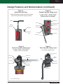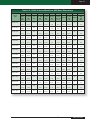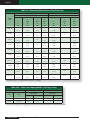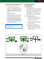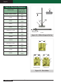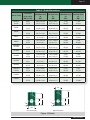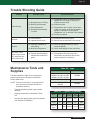
1
INSTALLATION, OPERATION AND MAINTENANCE MANUAL
19000 Series Consolidated® Safety Relief Valve
Series types include the
following design options:
• O-Ring Seat Seal (DA)
• 19096M-DA-BP
www.dresser.com
Page 2
19000 (April/2009)
19000 Series Consolidated® Safety Relief Valve
Page 3
Table of Contents
Page
Safety Sign and Label System ........................................................................................................................... 5
Safety Alerts! Read – Understand – Practice.................................................................................................. 6
Terminology for Safety Relief Valves................................................................................................................. 7
Introduction.......................................................................................................................................................... 8
Design Features and Nomenclature .................................................................................................................. 9
Handling, Storage, and Pre-Installation .......................................................................................................... 12
Recommended Installation Practices .............................................................................................................. 13
Mounting Position ......................................................................................................................................... 13
Inlet Piping .................................................................................................................................................... 13
Outlet Piping ................................................................................................................................................. 14
Disassembly Instructions ................................................................................................................................. 15
General Information ...................................................................................................................................... 15
Metal Seat Valves (MS)................................................................................................................................. 16
O-Ring Seat Seal Valves (DA) ........................................................................................................... 16
Cleaning ............................................................................................................................................................. 16
Parts Inspection................................................................................................................................................. 17
Base .............................................................................................................................................................. 17
Metal Seat (MS) Disc .................................................................................................................................... 17
O-Ring Seat Seal (DA) Assembly ................................................................................................................. 17
Bonnet ........................................................................................................................................................... 17
Metal Seat (MS) Disc Holder......................................................................................................................... 17
O-Ring (DA) Disc Holder ............................................................................................................................... 17
Guide ............................................................................................................................................................ 17
Spindle .......................................................................................................................................................... 18
Spring ............................................................................................................................................................ 18
Spring Washers............................................................................................................................................. 18
Adjusting Screw ............................................................................................................................................ 18
Maintenance Instructions ................................................................................................................................. 18
Metal Seat Valves (MS)................................................................................................................................. 18
O-Ring Seat Seal Valves (DA) ...................................................................................................................... 25
Checking Spindle Concentricity .................................................................................................................... 25
Reassembly and Lubrication............................................................................................................................ 28
Metal Seat Valves (MS)................................................................................................................................. 28
O-Ring Seat Valves (DA) .............................................................................................................................. 29
Setting and Testing ........................................................................................................................................... 29
General Information ...................................................................................................................................... 29
Test Equipment ............................................................................................................................................. 29
Test Media..................................................................................................................................................... 30
Setting the Valve ........................................................................................................................................... 30
Set Pressure Compensation ......................................................................................................................... 31
Blowdown ...................................................................................................................................................... 31
Simmer .......................................................................................................................................................... 31
Seat Leakage ................................................................................................................................................ 31
Back Pressure Tests ..................................................................................................................................... 32
19000 Series Consolidated® Safety Relief Valve
19000 (April/2009)
Page 4
Page
Hydrostatic Testing and Gagging .................................................................................................................... 32
Manual Popping of the Valve ........................................................................................................................... 32
Addendum: the 19096M-DA-BP Valve ............................................................................................................. 33
Introduction ................................................................................................................................................... 33
Changes in this Variation .............................................................................................................................. 34
Disassembly .................................................................................................................................................. 34
Parts Inspection ............................................................................................................................................ 34
Bonnet Top ............................................................................................................................................. 34
Bonnet Bottom ........................................................................................................................................ 34
Backup Plate .......................................................................................................................................... 34
Spindle.................................................................................................................................................... 34
Spindle O-Ring ....................................................................................................................................... 34
Backup Plate O-Ring .............................................................................................................................. 34
Seat O-Ring ............................................................................................................................................ 35
Re-assembly and Lubrication ....................................................................................................................... 35
Setting and Testing........................................................................................................................................ 37
General Information ................................................................................................................................ 37
Test Equipment ....................................................................................................................................... 37
Test Media .............................................................................................................................................. 37
Setting the Valve..................................................................................................................................... 37
Blowdown ............................................................................................................................................... 37
Seat Leakage ......................................................................................................................................... 37
Back Pressure Testing ............................................................................................................................ 38
Trouble Shooting Guide ................................................................................................................................... 39
Maintenance Tools and Supplies ..................................................................................................................... 39
Replacement Parts Planning............................................................................................................................ 40
General Information ...................................................................................................................................... 40
Inventory Planning ........................................................................................................................................ 40
Replacement Parts List ................................................................................................................................. 40
Identification and Ordering Essentials .......................................................................................................... 40
Genuine Dresser Parts ..................................................................................................................................... 40
Recommended Spare Parts for 19000 Series SRVs ...................................................................................... 41
Manufacturer’s Warranty, Field Service, Training, and Repair Program...................................................... 42
Warranty Information..................................................................................................................................... 42
Factory Repair Facilities ............................................................................................................................... 42
Safety Relief Valve Maintenance Training..................................................................................................... 42
Field Service ................................................................................................................................................. 43
Sales Office Locations...................................................................................................................................... 44
19000 (April/2009)
19000 Series Consolidated® Safety Relief Valve
Page 5
Safety Sign and Label System
Appropriate safety labels have been included in the practices and procedures
throughout this manual. The labels communicate:
•
•
•
•
Level of hazard seriousness
Nature of the hazard
Consequence of human or product interaction with the hazard
Instructions on how to avoid the hazard
!
DANGER
The top panel describes the
level of hazard seriousness
(DANGER or CAUTION).
!
CAUTION
The center panel contains a
pictorial that communicates
the nature and possible
consequence of the hazard.
The pictorial may depict
preventive measures to
take, such as wearing
protective equipment.
Do not remove bolts
if pressurized.
This will result in
serious personal
injury or death.
The bottom panel
contains an instruction
message on how to avoid
the hazard. This message
may give a more precise
definition of the hazard
and the consequences of
the hazard.
Wear necessary
protective
equipment to
prevent possible
injury.
ATTENTION! labels are horizontal bands describing special situations
and issues that could potentially damage the SRV.
ATTENTION!
Exercise care when inserting a rod or pipe in the outlet. Ensure the
valve nozzle is not damaged during the operation.
NOTE:
Any service questions not covered in this manual should be referred to
Dresser Consolidated Field Service Department, Phone + (1) (318) 640-6055.
In addition, you can contact your local Green Tag® Center or Dresser
Consolidated authorized sales representative (contact information can be
found on pages 44 & 45).
19000 Series Consolidated® Safety Relief Valve
19000 (April/2009)
Page 6
Safety Alerts! Read – Understand – Practice
Danger Alerts
•
A DANGER alert describes actions that may cause
severe personal injury or death. In addition, it
may provide preventive measures to avoid severe
personal injury or death.
Always perform correct service and repair.
Incorrect service and repair can result in
product or property damage or severe
personal injury or death.
•
DANGER alerts are not all-inclusive. Dresser
Consolidated cannot know all conceivable service
methods nor evaluate all potential hazards. Some
dangers are listed below:
Always use the correct tool for a job. The
misuse of a tool or the use of an improper
tool can result in personal injury, damage to
product or property.
•
Ensure the proper “health physics”
procedures are followed, if applicable,
before starting operation in a radioactive
environment.
•
High temperature/pressure can cause injury.
Ensure all system pressure is absent before
repairing or removing valves.
•
Do not stand in front of a valve outlet when
discharging. STAND CLEAR OF VALVE to
avoid exposure to trapped, corrosive media.
•
Exercise extreme caution when inspecting a
pressure relief valve for leakage.
•
Allow the system to cool to room temperature
before cleaning, servicing or repairing. Hot
components or fluids can cause severe
personal injury or death.
•
Always read and comply with safety labels
on all containers. Do not remove or deface
container labels. Improper handling or misuse
could result in severe personal injury or
death.
•
Never use pressurized fluids/gas/air to clean
clothing or body parts. Never use body
parts to check for leaks, flow rates or areas.
Pressurized fluids/gas/air injected into or near
the body can cause severe personal injury or
death.
•
It is the owner’s responsibility to specify and
provide protective wear to protect persons
from pressurized or heated parts. Contact
with pressurized or heated parts can result in
severe personal injury or death.
•
Do not work or allow anyone under the
influence of intoxicants or narcotics to work
on or around pressurized systems. Workers
under the influence of intoxicants or narcotics
are a hazard to themselves and other
employees. Actions taken by an intoxicated
employee can result in severe personal injury
or death to themselves or others.
19000 (April/2009)
Caution Alerts
CAUTION alerts describe actions that may result
in a personal injury. In addition, they may describe
preventive measures that must be taken to avoid
personal injury. Some caution alerts are listed
below.
•
Heed all service manual warnings. Read
installation instructions before installing
valve(s).
•
Wear hearing protection when testing or
operating valves.
•
Wear appropriate eye and clothing protection.
•
Wear protective breathing apparatus to
protect against toxic media.
19000 Series Consolidated® Safety Relief Valve
Page 7
Terminology for Safety Relief Valves (SRV)
•
Accumulation—the pressure increase over
the maximum allowable working pressure of
the vessel during discharge through the SRV,
expressed as a percentage of that pressure
or in actual pressure units.
•
Backpressure—the pressure on the
discharge side of the SRV:
Built-up Backpressure—the pressure that
develops at the valve outlet, after the SRV
has been opened, as a result of flow.
•
Operating Pressure—the gauge pressure
to which the vessel is normally subjected in
service. A suitable margin is provided between
operating pressure and maximum allowable
working pressure. For reliability of the valve,
the operating pressure should be at least 10%
under the maximum allowable working pressure
or 5 psi (.34 bar), whichever is greater.
•
Overpressure—a pressure increase over the
set pressure of the primary relieving device.
Overpressure is similar to accumulation when
the relieving device is set at the maximum
allowable working pressure of the vessel.
Normally, overpressure is expressed as a
percentage of set pressure.
•
Rated Capacity—the percentage of measured
flow at an authorized percent overpressure
permitted by the applicable code. Rated
capacity is generally expressed in pounds per
hour (lb/hr) for vapors, standard cubic feet per
minute (SCFM) or m3/min for gases, and in
gallons per minute (GPM) for liquids.
•
Relief Valve—an automatic pressure-relieving
device, actuated by static pressure upstream
from the valve. A relief valve is used primarily
for liquid service.
•
Safety Relief Valve (SRV)—an automatic
pressure-relieving device used as either
a safety or relief valve, depending upon
application. The SRV is used to protect
personnel and equipment by preventing
excessive overpressure.
•
Safety Valve—an automatic pressurerelieving device actuated by the static pressure
upstream of the valve and characterized by
a rapid opening or “pop” action. It is used for
steam, gas or vapor service.
•
Set Pressure—the gauge pressure at the
valve inlet for which the relief valve has been
adjusted to open under service conditions.
In liquid service, the inlet pressure at which
the valve starts to discharge determines set
pressure. In gas or vapor service, the inlet
pressure at which the valve pops determines
the set pressure.
•
Simmer—the audible passage of a gas or
vapor across the seating surfaces just before
“pop.” The difference between this start-toopen pressure and the set pressure is called
“simmer.” Simmer is generally expressed as a
percentage of set pressure.
Superimposed Backpressure—the
pressure in the discharge header before the
SRV is opened.
Constant Backpressure—the superimposed
backpressure that is constant with time.
Variable Backpressure—the superimposed
backpressure that varies with time.
•
•
•
Blowdown—the difference between set
pressure and re-seating pressure of the
SRV, expressed as a percentage of the set
pressure or in actual pressure units.
Cold Differential Test Pressure—the
pressure at which the valve is adjusted
to open on the test stand. This pressure
includes the corrections for backpressure
and/or temperature service conditions.
Differential Between Operating and Set
Pressures—Valves installed in process
services will generally give best results if
the operating pressure does not exceed
90% of the set pressure. However, on
pump and compressor discharge lines, the
differential required between the operating
and set pressures may be greater because
of pressure pulsations coming from a
reciprocating piston. The valve should be
set as far above the operating pressure as
possible.
•
Lift—the actual travel of the disc away from
the closed position when a valve is relieving.
•
Maximum Allowable Working Pressure—
the maximum gauge pressure permissible
in a vessel at a designated temperature.
A vessel may not be operated above this
pressure, or its equivalent, at any metal
temperature other than that used in its design.
Consequently, for that metal temperature, it
is the highest pressure at which the primary
pressure SRV is set to open.
19000 Series Consolidated® Safety Relief Valve
19000 (April/2009)
Page 8
Introduction
Design Options
The Consolidated® Series 19000 portable pressure
relief valves are designed to meet ASME Section
VIII requirements for fixed blowdown pressure
relief valves and liquid relief valves. They may be
used for various media such as air, liquids, process
steam and hydrocarbons and may serve as either
a safety valve or a relief valve, depending upon the
application.
O-Ring Seat Seal Valves
All 19000 Series Valves are available with an
O-Ring seat seal as a design option. This optional
design is bubble tight at 97% of set pressures over
100 psig, in order to meet application requirements
beyond the normal capabilities of metal to metal
seat valves. Consolidated Series 19000 Valves with
the O-Ring seat seal option are identified by the
suffix DA. (See Table X on page 31.)
Design Features and
Nomenclature
General Information
The Series 19000 portable safety relief valve
has 316 stainless steel trim as standard material.
Reliable performance and easy maintenance
procedures are characteristics of this valve, when
properly installed in suitable applications for its
design.
The 19000 Series SRV has three pressure
classes—19000L 5-290 psig, 19000M 291-2000
psig and 19000H 2001 psig and up. Standard
19000 parts are used for both liquid applications
and gas applications. It is designed for short
blowdown on all types of media, typically less than
10%.
All 19000 Series safety relief valves have fixed
blowdown. This means that the parts are designed
so that there is no blowdown adjustment required
when setting or testing the valve.
19000 (April/2009)
Lifting Levers, Caps and Gags
All 19000 Series Valves are designed so that field
conversion from the standard screwed cap to a
plain lifting lever cap, or to a packed lifting lever cap
(or vice versa), does not require valve disassembly
or resetting. The lifting lever option is designed to
open the valve at 75% of the valve set pressure, in
compliance with ASME Code Section VIII. Further,
all available 19000 Series Valve caps may be
equipped with a gag upon customer request.
Inlet/Outlet Connections
All 19000 Series Valves can be provided by Dresser
Consolidated with flanged, or socket weld inlet and
outlet connections, upon customer request.
Nomenclature
Applicable valve nomenclature for Types 19000
Male and Female inlet configurations are
illustrated in Figures 1 through 3. Relevant parts
nomenclature for optional lifting levers, caps and
the gag, as applicable, is provided in Figures 4
through 7.
19000 Series Consolidated® Safety Relief Valve
Page 9
Design Features and Nomenclature
Screwed Cap (15)
Spindle (6)
Adjusting Screw (9)
Adjusting Screw Locknut (10)
Cap Gasket (14)
Spring Washers (7)
Spring (8)
Bonnet (5)
Disc Holder (3)
Disc (2)
Guide (4)
Base (1)
Spindle (6)
19000-2 Design
Disc (2)
Disc Holder (3)
19000-2 Design
Guide (4)
19000-1 Design
Figure 1 – Metal Seat (MS) Valves
(Male NPT Inlet)
Figure 2 – Metal Seat (MS) Valves
(Female NPT Inlet)
19096L, 19110L, 19126L, 19226L, 19096M,
19110M, 19126M and 19226M
19096L, 19110L, 19126L, 19226L, 19357L, 19567L,
19096M, 19110M, 19126M, 19226M, 19357M, 19567M,
19096H, 19110H, 19126H and 19226H
19000 Series Consolidated® Safety Relief Valve
19000 (April/2009)
Page 10
Design Features and Nomenclature (continued)
Screwed Cap (15)
Spindle (6)
Adjusting Screw (9)
Adjusting Screw Locknut (10)
Cap Gasket (14)
Spring Washers (7)
Spring (8)
Bonnet (5)
Disc Holder (3)
Disc (2)
Guide (4)
Base (1)
Retainer
Lockscrew (18)
Disc
Holder (3)
O-Ring
Seat Seal (17)
O-Ring
Retainer (16)
Base (1)
Figure 3 – O-Ring Soft Seat (DA) Valves
Types 19000-DA
19000 (April/2009)
19000 Series Consolidated® Safety Relief Valve
Page 11
Design Features and Nomenclature (continued)
Figure 4
Typical Cap with Gag
Figure 5
Packed Cap with Lifting Lever*
For types 19096L, 19096M, 19096H,
19110H, 19110L, 19110M, 19126L,
19126M, 19226L and 19226M.
Both the standard screwed cap and the optional
caps can be provided with a gag, if required.
Gag Bolt
Packed Cap
Bushing
Standard
Screwed Cap
Release Lock Nut
Release Nut
Drive Pin
Sealing Plug
Cam Shaft
Bushing Gasket
Sealing Plug
Gasket
O-Ring
Cap Gasket
Lifting Lever
Figure 6
Packed Cap with Lifting Lever*
For types 19126H, 19226H, 19357L,
19357M, 19567L and 19567M.
Figure 7
Plain Cap with Lifting Lever*
For all series 19000 valves.
Plain Cap
Lifting Fork
Lifting Shaft
Packed Cap
Lifting Lever
Release
Lock Nut
Living
Lever
Packing
Lever Pin
Release Locknut
Packing Nut
Release Nut
Release Nut
Cap Gasket
Cap Screw
*Can be provided with a gag.
19000 Series Consolidated® Safety Relief Valve
19000 (April/2009)
Page 12
Handling, Storage and Pre-Installation
Handling
Valves should not be shipped with the inlet flange
down. These valves should be kept in their factory
foam-filled carton until installation.
ATTENTION!
Never lift the valve by the lifting lever.
ATTENTION!
Handle carefully. Do not drop or strike the
valve.
Do not subject SRVs, either crated or uncrated, to
sharp impact. Ensure that the valve is not bumped
or dropped during loading or unloading. While
hoisting the valve, take care to prevent bumping
the valve against steel structures and other objects.
Particular care needs to be taken when handling
screwed/portable valves to avoid damage to
external inlet threads.
ATTENTION!
Prevent dust and debris from entering inlet
or outlet of the valve.
Storage
Store SRVs in a dry environment and protect them
from the weather. Do not remove the valve from the
skids or crates until immediately before installation.
Do not remove flange protectors and seating plugs
until the valve is ready to be bolted into place
during the installation.
Screwed/portable valves should be kept in their
factory foam-filled carton until installation to avoid
damage to external inlet threads.
Pre-Installation
When SRVs are uncrated and the flange protectors
or sealing plugs are removed, exercise meticulous
care to prevent dirt and other foreign materials from
entering the inlet and outlet ports while bolting the
valve in place.
19000 (April/2009)
19000 Series Consolidated® Safety Relief Valve
Page 13
!
DANGER
Recommended Installation Practices
Mounting Position
Mount SRVs in a vertical (upright) position (in accordance with API RP 530 Part
II). Installing a safety relief valve in any position other than vertical (±1 degree) will
adversely affect its operation as a result of the induced misalignment of moving parts.
Mount safety relief
valves in a vertical,
upright position
only.
!
DANGER
A stop valve may be placed between the pressure vessel and its relief valve only as
permitted by code regulations. If a stop valve is located between the pressure vessel
and SRV, the stop valve port area should equal or exceed the nominal internal area
associated with the pipe size of the SRV inlet. The pressure drop from the vessel to
the SRV shall not exceed 3% of the valve’s set pressure when flowing at full capacity.
The threaded inlet and outlet ports and sealing faces of the valve and all connecting
piping must be free from dirt, sediment and scale.
Ensure all flange bolts are drawn evenly to prevent distortion of the valve body and
the inlet nozzle.
Do not mount valve
at the end of pipe
through which there is
normally no flow or
near elbows, tees,
bends, etc.
!
CAUTION
In the case of screwed/portable valves, use caution to avoid unscrewing bonnet
from the base; if a pipe wrench is used to install or remove the base, ensure that
the wrench is placed on the flats of the base and not on the bonnet. If the bonnet/
base joint is broken, the valve should be retested to insure proper set pressure and
function of the valve.
Position SRVs for easy access and/or removal so that servicing can be properly
performed. Ensure sufficient working space is provided around and above the valve.
Inlet Piping
The inlet piping (see Figure 8) to the valve should be short and directly from the
vessel or equipment being protected. The radius of the connection to the vessel
should permit smooth flow to the valve. Avoid sharp corners. If this is not practical,
then the inlet should be at least one additional pipe diameter larger.
Heed all service
manual warnings.
Read installation
instructions before
installing valve(s).
The pressure drop from the vessel to the valve shall not exceed 3% of valve set
pressure when the valve is allowing full capacity flow. The inlet piping must never be
smaller in diameter than the inlet connection of the valve. Excessive pressure drop in
gas, vapor or flashing-liquid service at the inlet of the SRV will cause the extremely
rapid opening and closing of the valve, which is known as “chattering.” Chattering will
result in lowered capacity and damage to the seating surfaces. The most desirable
installation is that in which the nominal size of the inlet piping is the same as, or
greater than, the nominal size of the valve inlet and in which the length does not
exceed the face-to-face dimensions of a standard tee of the required pressure class.
P.D.
P.D.
P.D.
P.D.
(from protected equipment)
Vessel
Vessel
Vessel
Figure 8
The pressure drop (P.D.) between the source of pressure in the protected equipment and
the pressure relief valve inlet is not to exceed 3% of the valve set pressure.
19000 Series Consolidated® Safety Relief Valve
19000 (April/2009)
Page 14
Do not locate SRV inlets where excessive
turbulence is present, such as near elbows, tees,
bends, orifice plates or throttling valves.
Section VIII of the ASME Boiler and Pressure
Vessel Code requires the inlet connection design
to consider stress conditions during valve operation
caused by external loading, vibration and loads due
to thermal expansion of the discharge piping.
The determination of reaction forces during valve
discharge is the responsibility of the vessel and/or
piping designer. Dresser Consolidated publishes
certain technical information about reaction forces
under various fluid flow conditions, but assumes no
liability for the calculations and design of the inlet
piping.
External loading, by poorly designed discharge
piping and support systems, and forced alignment
of discharge piping can cause excessive stresses
and distortions in the valve as well as the inlet
piping. The stresses in the valve may cause a
malfunction or leak. Therefore, discharge piping
must be independently supported and carefully
aligned.
Vibrations in the inlet piping systems may cause
valve seat leakage and/or fatigue failure. These
vibrations may cause the disc seat to slide back
and forth across the nozzle seat and may result
in damage to the seating surfaces. Also, vibration
may cause separation of the seating surfaces and
premature wear to valve parts. Low-frequency
vibrations are more detrimental to SRV tightness
than high-frequency vibrations. This effect can be
minimized by providing a larger difference between
the operating pressure of the system and the
set pressure of the valve, particularly under high
frequency conditions.
Temperature changes in the discharge piping may
be caused by fluid flowing from the discharge of
the valve or by prolonged exposure to the sun or
heat radiated from nearby equipment. A change
in the discharge piping temperature will cause
a change in the length of the piping, which may
cause stresses to be transmitted to the SRV and its
inlet piping. Proper support, anchoring or provision
for flexibility of the discharge piping can prevent
stresses caused by thermal changes. Do not use
fixed supports.
19000 (April/2009)
Outlet Piping
Alignment of the internal parts of the SRV is
important to ensure proper operation (see
Figure 9). Although the valve body will withstand
a considerable mechanical load, unsupported
discharge piping consisting of more than a
companion flange (for flange outlet valves),
long-radius elbow and a short vertical pipe is not
recommended. Use spring supports to connect
outlet piping to aid in preventing thermal expansion
from creating strains on the valve. The discharge
piping should be designed to allow for vessel
expansion as well as expansion of the discharge
pipe itself. These design issues are particularly
important on long distance lines.
A continual oscillation of the discharge piping
(wind loads) may induce stress distortion in the
valve body. The resultant movement of the valve’s
internal parts may cause leakage.
Where possible, use properly supported drainage
piping to prevent the collection of water or corrosive
liquid in the valve body.
When two or more valves are piped to discharge
into a common header, the built-up backpressure
resulting from the opening of one (or more) valve(s)
may cause a superimposed backpressure in the
remaining valves. Under these conditions, the use
of the 19096-DA-BP model is recommended (see
page 33).
In every case, the nominal discharge pipe size must
be at least as large as the nominal size of the SRV
outlet flange. In the case of long discharge piping,
the nominal discharge pipe size must sometimes be
much larger.
As a final point, the discharge piping size is never
less than the size of the valve outlet, nor heavier
than schedule 40 pipe size. In addition, the
discharge piping must be designed to limit the total
backpressure to a maximum of 10% of the valve set
pressure, or 400 psi, whichever is smaller.
ATTENTION!
Undersized discharge piping could create
built-up backpressure.
19000 Series Consolidated® Safety Relief Valve
Page 15
Cap may be required
for weather protection
WR
ON
G
Long-Radius
Elbow
For a closed system, always
keep piping strains isolated from
the pressure relief valve,
regardless of process operation
and temperature.
Vessel
Vessel
Figure 9 – Outlet Piping Considerations
!
DANGER
Disassembly Instructions
General Information
Many pressure
vessels protected
by Consolidated®
Safety Relief
Valves contain
dangerous
materials.
Decontaminate and
clean the valve
inlet, outlet, and all
external surfaces in
accordance with
the cleaning and
decontaminating
recommendations
in the appropriate
Material Safety
Data Sheet.
!
DANGER
Before
disassembling the
valve, ensure there
is no media
pressure in the
vessel.
Consolidated Safety Relief Valves can be easily disassembled for inspection,
reconditioning seats or replacing internal parts. Appropriate set pressure can
be established after reassembly. (Refer to Figures 1 through Figure 7 for Parts
Nomenclature.)
NOTES:
• Before starting to disassemble the valve, be sure there is
no media pressure in the vessel.
!
CAUTION
Wear necessary
protective equipment
to prevent possible
injury.
!
CAUTION
•
Many pressure vessels that are protected by Consolidated
Safety Relief Valves contain dangerous materials.
•
Decontaminate and clean the valve inlet and outlet and
all external surfaces in accordance with the cleaning and
decontaminating recommendations in the appropriate
Material Safety Data Sheet.
•
Parts from one valve should not be interchanged with parts
from another valve.
ATTENTION!
Do not interchange parts from one valve with parts from
another valve.
Valve caps and
bonnets can trap
fluids. Use caution
when removing to
prevent injury or
environmental
damage.
19000 Series Consolidated® Safety Relief Valve
19000 (April/2009)
Page 16
SRV Disassembly
Metal Seat Valves (See Figures 1 & 2)
(a)
Remove the cap (15) (including lifting gear, if
any); then, remove the cap (14) gasket.
(b)
Measure the position of the valve adjusting
screw (9) and record before removal.
Measure from the top of the screw to the
adjusting screw locknut (10).
(c)
Loosen the adjusting screw locknut (10)
and remove the adjusting screw (9) from the
bonnet (5).
(d)
Unscrew the bonnet (5) from the base (1).
(e)
Remove the spindle (6), spring (8), and spring
washers (7).
(f)
Remove the guide (4), disc holder (3), and
disc (2) from the base (1).
Cleaning
19000 Series Safety Relief Valve internal parts
may be cleaned with industrial solvents, cleaning
solutions and wire brushes.
If you are using cleaning solvents, take precautions
to protect yourself from potential danger from
breathing fumes, chemical burns or explosion. See
the solvent’s Material Safety Data Sheet for safe
handling recommendations and equipment. It is not
recommended to “sandblast” internal parts as it can
reduce the dimensions of the parts. The
base (1), bonnet (5) and cap (15) castings may
be sandblasted with care not to erode internal
surfaces or damage machined surfaces. If grit
blasting is required, the use of glass bead media is
recommended.
O-Ring Seat Seal Valves (DA) (See Figure 3)
!
DANGER
Follow steps (a) through (e) for Metal Seat
Valves above.
(f)
Remove the guide (4) and O-Ring disc holder
assembly from the base.
(g)
Remove the retainer lockscrew (18) and the
O-Ring retainer (16).
(h)
Carefully remove the O-Ring Seat Seal (17).
Be sure not to damage the O-Ring groove in
the disc holder (3).
19000 (April/2009)
19000 Series Consolidated® Safety Relief Valve
Follow
recommendations
for safe handling in
the solvent’s
Material Safety Data
Sheet and observe
safe practices for
any cleaning
method.
Page 17
Parts Inspection
Base (1) – the base should be
replaced if:
(a)
Bonnet (5) – the bonnet
should be replaced if:
(a)
Threads are stripped, torn or galled.
(b)
The guide seating surface is scratched,
nicked, corroded or leaks.
(c)
Condition is porous, corroded or distorted.
Seat Surface
(i)
(ii)
Metal Seated-Seat surface “N” (see
Figure 12), is scratched, nicked,
corroded, leaks or is too wide and cannot
be machined (see Table I and c.ii.ii on
page 20).
O-Ring Seat surface “N” (see insert,
Figure 12), is scratched, nicked, corroded
or leaks.
(b)
Threads (all) are torn, stripped or galled.
(c)
Guide seating surface “U” is scratched,
nicked, corroded or dimension “L” is less than
“L” minimum (see Figure 12, Table II, and
c.ii.ii on page 20).
(d)
Seat step “F” is at or above minimum
listed in Table II. “F” can be reestablished
by machining as long as “L” stays within
tolerance (see c.ii.ii on page 20).
Metal Seat Disc (2) – the metal
seat disc should be replaced
if:
Metal Seat Disc Holder (3) –
the disc holder should be
replaced if:
(a)
The outside surface is worn, egged or galled
and/or cannot meet “H” dimension.
(b)
The spindle pocket bearing surface is galled
or pitted.
(c)
The disc seating surface “Y” is galled or pitted
(see Figure 15).
O-Ring Disc Holder (3) – the
O-Ring disc holder should be
replaced if:
(a)
The outside surface is worn, egged or galled
and/or cannot meet “H” dimension (see
Figure 15).
(b)
The spindle pocket bearing surface is galled
or pitted.
(a)
Seat surface “Y” (see Figure 13), is damaged
beyond lapping or machining limits.
(c)
The O-Ring groove is nicked, scratched or
pitted.
(b)
Seat relief height “R” is less than “R”
minimum and dimension “S” cannot be
maintained (see Table III).
(d)
The O-Ring retainer screw threads are torn,
stripped or galled.
(c)
Length “S” is less than “S” minimum (see
Table III).
O-Ring Seat Seal Assembly –
the O-Ring seat seal assembly
parts should be replaced as
follows:
(a)
O-Ring Seat Seal (17) – always replace.
(b)
O-Ring retainer (16)
(i)
Lapped seat relief height “R” is less than
“R” minimum and dimension “S” cannot be
maintained (see Figure 13 and Table III).
(ii)
Length “S” is less than “S” minimum (see
Table III).
Guide (4) – replace the guide
if:
(a)
The inside surface is worn, egged or galled.
(b)
Base and bonnet seating surfaces are
scratched, nicked, corroded or leaks.
(c)
Hole dimension “K” is out of tolerance (see
Figure 16 and Table V).
(d)
Guide Height Dimension “L” is out of
tolerance (see Figure 16 and Table V).
(e)
“J” dimension is not within tolerance (see
Figure 16 and Table V).
(iii) Retainer Lockscrew - Always replace.
19000 Series Consolidated® Safety Relief Valve
19000 (April/2009)
Page 18
Spindle (6) – replace the
spindle if:
(a)
The bearing surfaces are galled, pitted or
scratched
(b)
Threads are torn, stripped or galled.
(c)
The stem is bent (see Figure 14).
will enable maintenance personnel to do a
“professional” job of lapping seats:
(i)
Keep work materials clean.
(ii)
Always use a fresh lap. If signs of wearing
(out of flatness) are evident, recondition the
lap. Reconditioning of laps is accomplished
by lapping them on a flat lapping plate. The
lapping should be done with a figure-eight
motion as indicated in Figure 10. To assure
the best results when lapping seats, the laps
should be reconditioned after each usage.
Spring (8) – replace the
spring if:
(1)
The ends are not ground flat and parallel.
(2)
The coils are bent, pitted or unevenly spaced.
(3)
The spring cannot be properly identified
(spring chart).
ATTENTION!
19000 Series valve springs do not have
sufficient wire diameter to allow permanent
spring marking.
Spring Washers (7) – replace
the Spring Washers if:
(a)
The bearing surface is galled, pitted or
scratched.
(b)
Corrosion affects the centering of the spring.
Adjusting Screw (9) – replace
adjusting screw if:
(a)
Threads are torn, stripped or galled.
(b)
The bearing surfaces are galled, pitted or
scratched.
(c)
The adjustment flats are damaged or
rounded.
(iii) Apply a very thin layer of compound to the
lap. This will prevent rounding off the edges
of the seat.
(iv) Keep the lap squarely on the flat surface
and avoid any tendency to rock the lap
which causes rounding of the seat.
(v)
When lapping, keep a firm grip on the part
to prevent the possibility of dropping it and
damaging the seat.
(vi) Lap, using an eccentric, or figure-eight
motion, in all directions, while at the same
time, applying uniform pressure and rotating
the lap slowly (see Figure 10).
(vii) Replace the compound frequently after
wiping off the old compound, and apply
more pressure to speed the cutting action of
the compound.
(viii) To check the seating surfaces, remove all
compounds from both the seat and the lap.
Then, shine the seat with the same lap using
the lapping motion described above. Low
sections on the seating surface will show up
as a shadow in contrast to the shiny portion.
Lapping Plate
Ring Lap
Maintenance
Instructions
Metal Seat Valves (MS)
(a)
Precautions and Hints for Lapping Seats
Reconditioning of the seat surface may be
accomplished by lapping with a flat cast
iron ring lap coated with a 1000 grit lapping
compound or its equivalent (see Table
XIII). The following precautions and hints
19000 (April/2009)
19000 Series Consolidated® Safety Relief Valve
Figure 10 – Lapping Pattern
Page 19
If shadows are present, further lapping is
necessary and only laps known to be flat
should now be used. Only a few minutes
will be required to remove the shadows.
(ix) When the lapping is completed, any lines
appearing as cross scratches can be
removed by rotating the lap (which has
been wiped clean of compounds) on the
seat about its own axis.
(x)
(b)
The seat should now be thoroughly
cleaned using a lint-free cloth and a
cleansing fluid.
Lapping the Base Seat
The base seat may be reconditioned
using the lapping procedure; however, the
dimensions provided in Table I, should be
used to determine the seat width.
The seat width can be measured by the use
of a “Measuring Magnifier” (see Figure 11.A).
Dresser Consolidated recommends the use
of Model S1-34-35-37 (Bausch and Lomb
Optical Co.) or an equivalent. This is a seven
power glass with a ¾ inch scale showing
graduations of 0.005 inch. The use of this
scale in measuring the seat width is shown in
Figure 11.B.
If additional lighting is required for measuring
the seat, Dresser Consolidated suggests a
goose-neck flashlight similar to the Type A
Lamp Assembly Flashlight (Standard Molding
Corporation, Dayton, Ohio) or an equivalent.
Base
Width
Measuring
Magnifier
0
0.1
0.2
0.3
0...44
00.4
0.
0.5
0.66
0.7
Flat Seat
Base
5° Taper
Figure 11.A – Measuring Magnifier
Figure 11.B – Measuring Magnifier Detail
Table I – Dimensions for Determining Seat Width
Set Pressure
Nominal Lapped Seat Width
psig
barg
inches
mm
21-100
1.448-6.896
0.01-0.013
0.254-0.33
101-300
6.965-20.689
0.014-0.018
0.356-0.457
301-800
20.758-55.172
0.019-0.023
0.483-0.584
801-900
55.269-62.1
0.024-0.028
0.609-0.711
901-1000
62.169-69
0.029-0.033
0.737-0.838
1001-1100
69.069-75.9
0.034-0.038
0.864-0.965
1101-1200
75.969-82.8
0.039-0.043
0.991-1.092
1201-1300
82.869-89.7
0.044-0.048
1.118-1.219
1301-1400
89.769-96.6
0.049-0.053
1.245-1.346
1401-1500
96.669-103.5
0.054-0.058
1.372-1.473
1501-1600
103.569-110.4
0.059-0.063
1.499-1.6
1601-1700
110.469-117.3
0.064-0.07
1.626-1.778
1701+
117.369+
0.07 Maximum
1.778 Maximum
19000 Series Consolidated® Safety Relief Valve
19000 (April/2009)
Page 20
(c)
Machining the Base Seat
ATTENTION!
(i)
When the base seat cannot be repaired
by lapping, it can be machined as shown
in Figure 12, using the dimensions
provided in Table II.
(ii)
Dresser Consolidated recommends that
the following procedure be adhered to
when machining the base seat:
(ii.i)
19000H and 19000 DA bases have flat seats
(90° angle) across the entire seating surface
from B diameter to D diameter.
(d)
Using a four-jaw chuck, align the
base so that surfaces marked X
and Y run true within .001” on an
indicator.
Machining the Disc Seat
(i)
When the disc seat cannot be repaired by
lapping, it can be machined as shown in
Figure 13, using the dimensions provided
in Table III.
(ii)
Dresser Consolidated recommends that
the following procedure be adhered to
when machining the disc seat:
(ii.ii) Take light cuts on the seat surface
until all damage is removed. Reestablish dimensions “B”, “C”,
“F”, “G”, “H” and Angle I. When L
(minimum) is obtained, the base
should be replaced.
(ii.i) Grip the disc in a collet.
(ii.ii) True up the disc so that surfaces
marked X and Y run true within
.001” on an indicator.
(ii.iii) After all machining has been
accomplished, lap the seat using
same procedure for base seat.
(ii.iii) Take light cuts across the seating
surface until the damage is
removed. Dimensions “R” and “D”,
(and 15° angle when applicable)
must be maintained.
E
(ii.iv) The disc is now ready for lapping.
(See Table III-A for proper seat
width).
D
C
(ii.v) When the minimum thickness
dimension “S” is reached, the disc
should be replaced.
B
F
X
H
Angle I
(-1 design only)
J
Angle K
G
Y
U
Guide Seating
Surface
O-Ring Base
N (Flat Seat - 0.010 radius
on seat OD)
L
F (Refer to “O” dim in place of “F”
dim for liquid service 5-1000psig)
A
Metal Seat Base
Figure 12
Machining the Base Seat
19000 (April/2009)
19000 Series Consolidated® Safety Relief Valve
Page 21
Table II-A: 19000 Series Soft Seat (DA) Base Dimensions
A
VALVE
TYPE
19096L-DA
19110L-DA
19126L-DA
19226L-DA
19357L-DA
19567L-DA
19096M-DA
19110M-DA
19126M-DA
19226M-DA
19357M-DA
19567M-DA
19096H-DA
19110H-DA
19126H-DA
19226H-DA
B
C
D
E
F
G
H
IN.
(REF)
IN.
(± .002)
(MIN)
IN.
IN.
(± .002)
IN.
(± .003)
IN.
(± .005)
IN.
(± .005)
IN. (+ .002)
(- .003)
MM.
(REF)
MM.
(± .05)
MM.
MM.
(± .08)
MM.
(± .13)
MM.
(± .13)
MM.
(± .13)
MM. (+.05)
(-. 08)
0.35
0.395
8.89
10.03
0.375
0.395
9.525
10.03
0.401
0.453
10.19
11.51
0.537
0.606
13.64
15.39
0.675
0.762
17.15
19.35
0.85
0.96
21.59
24.38
0.35
0.395
8.89
10.03
0.375
0.395
9.525
0.401
10.19
11.51
0.537
0.606
13.64
15.39
0.675
0.762
17.15
0.85
21.59
24.38
0.35
0.395
FLAT
FLAT
FLAT
FLAT
0.457
0.503
.045*
0.188
0.784
11.61
12.78
1.143
4.78
19.91
0.457
0.503
.045*
0.188
0.784
11.61
12.78
1.143
4.78
19.91
0.523
0.579
.045*
0.216
0.784
13.28
14.71
1.143
5.49
19.91
0.701
0.781
.050*
0.289
1.034
17.81
19.84
1.27
7.34
26.26
I
ANGLE
J
IN.
(± .005)
K
ANGLE
MM.
(± .13)
FLAT
FLAT
FLAT
FLAT
0.02
0.508
0.02
0.508
0.023
0.584
0.03
0.762
30˚
30˚
30˚
0
IN.
(MIN)
Liquid Valve
Only
IN. (+.003)
(- .002)
MM.
(MIN)
MM (+.08)
(- .05)
0.187
.032*
4.75
0.813
0.187
.032*
4.75
0.813
0.187
.032*
4.75
0.813
0.187
.032*
4.75
0.813
0.881
0.987
.060*
0.363
1.503
22.38
25.07
1.524
9.22
38.18
1.109
1.247
.060*
0.457
1.503
28.17
31.67
1.524
11.61
38.18
0.457
0.503
0.045
0.188
0.789
11.61
12.78
1.143
4.78
20.04
0.457
0.503
0.045
0.188
0.789
10.03
11.61
12.78
1.143
4.78
20.04
0.762
4.75
0.453
0.523
0.579
0.08
0.216
0.789
0.03
0.187
13.28
14.71
2.032
5.49
20.04
FLAT
FLAT
FLAT
FLAT
FLAT
FLAT
FLAT
FLAT
0.038
30˚
L
0.965
0.048
1.219
0.03
FLAT
FLAT
0.03
0.781
0.08
0.21
1.034
19.84
2.032
5.33
26.26
0.881
0.987
0.09
0.363
1.548
19.35
22.38
25.07
2.286
9.22
39.32
0.965
0.96
1.109
1.247
0.125
0.3
1.526
0.048
28.17
31.67
3.175
7.62
38.76
0.457
0.503
0.045
0.188
1.038
FLAT
FLAT
30˚
FLAT
0.03
30˚
30˚
FLAT
0.038
30˚
0.03
0.25
.050*
6.35
1.27
0.187
0.187
0.187
4.75
30˚
250
6.35
30˚
1.219
FLAT
.040*
1.016
4.75
0.762
FLAT
0.25
6.35
4.75
0.762
0.701
FLAT
30˚
0.762
17.81
FLAT
30˚
0.25
6.35
30˚
0.187
8.89
10.03
11.61
12.78
1.143
4.78
26.37
0.762
4.75
0.375
0.395
0.457
0.503
0.045
0.188
1.038
0.03
0.187
9.525
10.03
11.61
12.78
1.143
4.78
26.37
0.762
4.75
0.401
0.453
0.523
0.579
0.045
0.156
1.502
0.03
0.187
10.19
11.51
13.28
14.71
1.143
3.96
38.15
0.537
0.606
0.701
0.781
0.05
0.21
1.504
13.64
15.39
17.81
19.84
1.27
5.33
38.2
FLAT
FLAT
FLAT
FLAT
FLAT
FLAT
0.762
0.03
0.762
30˚
30˚
30˚
4.75
0.187
4.75
* Soft seat (DA) valves for liquid service from 5 - 100 psig require a special base.
base Refer to Dimension O instead of Dimension F in this case
case.
** Angles in degrees
19000 Series Consolidated® Safety Relief Valve
19000 (April/2009)
Page 22
Table II-B: 19000-1 Series Metal Seat (MS) Base Dimensions
VALVE
TYPE
A
B
C
D
E
F
G
H
IN.
(REF)
IN.
(± .002)
(MIN)
IN.
IN.
(± .002)
IN.
(± .003)
IN.
(± .005)
IN.
(± .005)
IN. (+ .002)
(- .003)
MM.
(REF)
MM.
(± .05)
MM.
MM.
(± .08)
MM.
(± .13)
MM.
(± .13)
MM.
(± .13)
MM. (+ .05)
(- .08)
0.35
0.395
0.01
0.457
0.503
0.03
0.188
0.784
19096L-MS-1
I
ANGLE
J
IN.
(± .005)
MM.
(± .13)
10.03
0.25
11.61
12.78
0.762
4.78
19.91
0.401
0.453
0.01
0.523
0.579
0.03
0.216
0.784
19126L-MS-1
11.51
0.025
13.28
14.71
0.762
5.49
19.91
0.537
0.606
0.01
0.701
0.781
0.03
0.289
1.034
19226L-MS-1
15.39
0.025
17.81
19.84
0.762
7.34
26.26
0.675
0.762
0.01
0.881
0.987
0.038
0.363
1.503
19357L-MS-1
19.35
0.025
22.38
25.07
0.965
9.22
38.18
0.85
0.96
0.01
1.109
1.247
0.048
0.457
1.503
19567L-MS-1
24.38
0.025
28.17
31.67
1.219
11.61
38.18
0.35
0.395
0.01
0.457
0.503
0.03
0.188
0.784
19096M-MS-1
0.584
10.03
0.025
11.61
12.78
0.762
4.78
19.91
0.401
0.453
0.01
0.523
0.579
0.03
0.216
0.784
19126M-MS-1
11.51
0.025
13.28
14.71
0.762
5.49
19.91
0.537
0.606
0.01
0.701
0.781
0.03
0.289
1.034
19226M-M S-1
0.762
15.39
0.025
17.81
19.84
0.762
7.34
26.26
0.675
0.762
0.01
0.881
0.987
0.038
0.363
1.503
19357M-MS-1
19.35
0.025
22.38
25.07
0.965
9.22
38.18
0.85
0.96
0.01
1.109
1.247
0.048
0.457
1.503
19567M-MS-1
0.965
24.38
0.025
28.17
31.67
1.219
11.61
38.18
0.35
0.395
0.01
0.457
0.503
0.03
0.188
1.034
19096H-MS-1
10.03
0.401
0.453
19126H-MS-1
0.025
11.61
12.78
0.762
4.78
26.26
0.523
0.579
0.03
0.156
1.524
FLAT
10.19
11.51
1.219
0.537
0.606
19226H-MS-1
14.71
0.762
3.96
38.71
0.701
0.781
0.03
0.21
1.504
FLAT
13.64
19000 (April/2009)
15.39
19.84
0.762
5.33
19000 Series Consolidated® Safety Relief Valve
38.2
0.187
30˚
0.762
4.75
0.03
0.187
30˚
0.762
4.75
0.038
0.187
30˚
0.965
4.75
0.048
0.187
30˚
1.219
4.75
0.03
0.187
30˚
0.762
4.75
0.03
0.187
30˚
0.762
4.75
0.03
0.187
30˚
0.762
4.75
0.03
FLAT
17.81
4.75
0.03
FLAT
13.28
0.187
30˚
FLAT
8.89
4.75
0.048
5˚
21.59
0.187
30˚
5˚
17.15
4.75
0.038
15˚
13.64
0.187
30˚
15˚
10.19
4.75
0.03
15˚
8.89
0.187
30˚
5˚
21.59
4.75
0.023
5˚
17.15
MM.
(MIN)
0.187
0.508
15˚
13.64
L
IN.
(MIN)
30˚
15˚
10.19
ANGLE
0.02
15˚
8.89
K
0.187
30˚
0.762
4.75
Page 23
Table II-C: 19000-2 Series Metal Seat (MS) Base Dimensions
VALVE
TYPE
19096L-MS-2
19110L-MS-2
19126L-MS-2
19226L-MS-2
19357-MS-2
19567L-MS-2
19096M-MS-2
19110M-MS-2
19126M-MS-2
19226M-MS-2
19357M-MS-2
19567M-MS-2
19096H-MS-2
19110H-MS-2
19126H-MS-2
19226H-MS-2
A
B
C
D
F
G
H
IN.
(REF)
IN
(± .002)
(MIN)
IN
IN
(± .002)
IN
(± .002)
IN
(± .005)
IN (+.002)
(-0.003)
MM
(REF)
MM
(± 0.5)
MM
MM
(± .05)
MM
(± .05)
MM
(± .13)
MM (+ 05)
(-. 076)
0.35
0.408
0.457
0.022
0.19
0.784
FLAT
0.02
8.89
10.36
11.61
0.558
4.82
19.91
(90°)
0.508
0.375
0.408
9.525
10.36
0.401
0.463
10.19
11.75
0.537
0.625
13.64
15.87
0.675
0.796
17.15
19.35
0.85
1
21.59
25.39
0.35
0.408
8.89
10.36
0.375
0.408
9.525
10.36
0.401
0.463
10.19
11.75
0.537
0.625
13.64
15.87
0.675
0.796
17.15
19.35
0.85
1
21.59
25.39
0.35
0.395
8.89
10.013
0.375
0.395
9.525
10.013
0.401
0.444
10.19
11.255
0.537
0.616
13.64
15.615
N/A
N/A
N/A
N/A
N/A
N/A
N/A
N/A
N/A
N/A
N/A
N/A
N/A
N/A
N/A
N/A
I
ANGLE
J
IN
(± .002)
MM
(± .05)
0.457
0.022
0.19
0.784
FLAT
0.02
11.61
0.558
4.82
19.91
(90°)
0.508
0.523
0.022
0.216
0.784
FLAT
0.023
13.28
0.558
5.48
19.91
(90˚)
0.584
0.701
0.022
0.289
1.034
FLAT
0.03
17.81
0.558
7.34
26.26
(90°)
0.762
0.881
0.022
0.363
1.503
FLAT
0.038
22.38
0.558
9.22
38.18
(90°)
0.965
1.109
0.022
0.457
1.503
FLAT
0.048
28.17
0.558
11.61
38.18
(90°)
1.219
0.457
0.022
0.12
0.789
FLAT
0.03
11.61
0.558
3.048
20.04
(90°)
0.762
0.457
0.022
0.12
0.789
FLAT
0.03
11.61
0.558
3.048
20.04
(90°)
0.762
0.523
0.022
0.125
0.789
FLAT
0.03
13.28
0.558
3.175
20.04
(90°)
0.762
0.701
0.022
0.21
1.034
FLAT
0.03
17.81
0.558
5.334
26.26
(90°)
0.762
0.881
0.022
0.244
1.548
FLAT
0.038
22.38
0.558
6.19
39.32
(90°)
0.965
1.109
0.022
0.3
1.572
FLAT
0.048
28.17
0.558
7.62
39.92
(90°)
1.219
0.457
0.022
0.12
1.038
FLAT
0.03
11.61
0.558
3.048
26.37
-900
0.762
0.457
0.022
0.12
1.038
FLAT
0.03
11.61
0.558
3.048
26.37
(90°)
0.762
0.523
0.022
0.125
1.502
FLAT
0.03
13.28
0.558
3.175
38.15
(90°)
0.762
0.701
0.022
0.21
1.504
FLAT
0.03
17.81
0.558
5.334
38.2
(90°)
0.762
19000 Series Consolidated® Safety Relief Valve
K
ANGLE
30°
30˚
30°
30°
30°
30°
30°
30°
30°
30°
30°
30°
30°
30°
30°
30°
L
IN
(MIN)
MM
(MIN)
0.187
4.75
0.187
4.75
0.187
4.75
0.187
4.75
0.25
6.35
0.25
6.35
0.187
4.75
0.187
4.75
0.187
4.75
0.187
4.75
0.25
6.35
0.25
6.35
0.187
4.75
0.187
4.75
0.187
4.75
0.187
4.75
19000 (April/2009)
Page 24
Table III – Reworking Dimensions of the Disc Seat
Disc
“O” Ring Retainer
(Metal Seat)
(Soft Seat)
-1 only
VALVE
TYPE
-2 only
R
S
S
R
S
Q*
(MIN.)
(MIN.)
(MIN.)
Q*
(MIN.)
(MIN.)
IN.
IN.
IN.
IN.
IN.
IN.
IN.
(MM)
(MM)
(MM)
(MM)
(MM)
(MM)
0.461
0.025
0.243
0.234
0.426
(11.71)
(0.64)
(6.17)
(5.94)
(10.82)
0.461
0.025
0.243
0.491
0.426
(MM)
0.156
19096L, M
____
(3.06)
0.156
19096H
____
(11.71)
(0.64)
0.461
0.025
19110L, M
(6.17)
(12.47)
(10.82)
0.234
0.426
(3.06)
0.156
N/A
(11.71)
(0.64)
0.461
0.025
19110H
____
(5.94)
(10.82)
0.491
0.426
(3.06)
0.156
N/A
(11.71)
(0.64)
0.527
0.025
0.243
____
(12.47)
(10.82)
0.234
0.489
(3.06)
0.156
19126L, M
____
(13.39)
(0.64)
(6.17)
(5.94)
(12.42)
0.527
0.025
0.243
0.491
0.489
(3.06)
0.156
19126H
____
(13.39)
(0.64)
(6.17)
(12.47)
(12.42)
0.705
0.025
0.301
0.272
0.676
(3.06)
0.204
19226L*, M*
0.025
(17.91)
(0.64)
(7165)
(6.91)
(11.43)
0.705
0.025
0.301
0.540
0.676
(5.18)
0.204
19226H*
0.025
(17.91)
(0.64)
(7165)
(13.72)
(11.43)
.885
0.025
0.493
.454
.852
(5.18)
0.249
19357L*, M*
0.025
(22.48)
(0.64)
12.52
(11.53)
(21.64)
1.113
0.025
0.493
0.473
1.056
(6.32)
0.249
19567L*, M*
0.025
(28.27)
(0.64)
12.52
(12.01)
(26.82)
(6.32)
* These valves have a 15° angle as shown in Figure 13 (-2 Design).
Table III-A – Disc Seat Lapping Width (-2 Design Only)
Set Pressure
PSI
Disc Seat Width
BAR
19096, 19110, 19126
VALVE TYPE
19226, 19357, 19567
VALVE TYPE
IN.
(MM)
IN.
(MM)
5-800
0.345.55.158
Flat
Flat
.020
.510
801-Up
55.159-Up
Flat
Flat
*
*
* Add 0.005 In. (0.125mm) per 100 psi (6.896 bar), until disc seat width has reached the maximum available width.
19000 (April/2009)
19000 Series Consolidated® Safety Relief Valve
Page 25
Checking Spindle
Concentricity
O-Ring Seat Seal Valves (DA)
(a)
Replacing the O-Ring Retainer (16)
(a)
If slight damage is present, the O-Ring
Retainer can be refurbished by either lapping
or machining. O-Ring Retainer should be
replaced if severely damaged or if dimension
S (minimum) is exceeded (see Figure 13 and
Table III).
(b)
It is important that the spindle (6) of a safety
relief valve be straight in order to transmit the
spring load to the disc without lateral binding.
Over-gagging is one of the common causes
of bent spindles. To check the essential
working surfaces of the spindle, the method
stated in the next section is recommended.
Polishing the Base Seat
Normally the base seating area on this type
of valve is not damaged, since the O-Ring
absorbs the impact when foreign material is
trapped between the O-Ring and the base
seating area. The O-Ring will therefore hold
a bubble tight seal with slight indications on
the base seating surface. Nevertheless, slight
indications on the base seat surface may be
removed by lapping the base.
(b)
ATTENTION!
Q
32
X
S min.
V-Block Support Set Up
(i)
The ball-pointed spindles should be
placed in a piece of material, B, that has
been recessed to permit free rotation of
the spindle (see Figure 14).
(ii)
Support the spindle with a V-block A,
placed near the upper end of the spindle,
but below the threads.
(iii) Apply a machinist’s indicator at
approximately 45° to the outer edge of
the spring washer seat at “C”. Rotate
the spindle. The total indicator reading
should not exceed .005”. Straighten the
spindle, if necessary.
The O-Ring always should be replaced to
insure seat tightness.
Q
General Information
X
(-1 Disc)
15°
R min.
S min.
S
R min.
Y
Q
Bearing
Surface
“T”
15°
Y
R min.
(-2 Disc)
(O-Ring Retainer)
15°
Figure 13
19000 Series Consolidated® Safety Relief Valve
19000 (April/2009)
Page 26
Table IV - Disc Holder Dimensions
H Diameter
VALVE TYPE
A
(top view)
IN. (± 0.001)
MM. (± 0.03)
19096L, 19096 & 19110L
1.000
C
25.40
Spring
Washer
Seat
45°
B
1.26
19357L
31.93
1.58
19567L
40.21
19096M & 19110M
0.65
16.61
0.75
19126M
18.97
1.000
19226M
Bearing Surface “T”
(-2 Spindle)
Figure 14 – V-Block Support Set Up
F
25.40
1.26
19357M
31.93
19567M & 19110H
19226H
A
18.97
19226L
19126H
16.61
7.47
19126L
19096H
0.65
H dia.
1.58
40.21
Z
0.65
16.61
Y
0.75
18.97
-2 Metal Seat Disc Holder
1.000
25.40
H dia.
H dia.
X
X
Z
Z
W
V
Y
Y
Metal Seat Disc Holder
O-Ring Disc Holder
Figure 15 – Disc Holder
19000 (April/2009)
19000 Series Consolidated® Safety Relief Valve
Page 27
Table V - Guide Dimensions
J Diameter
VALVE TYPE
K
(MS-Metal Seat)
K
(DA-Soft Seat)
L mm
(MS-Metal Seat)
L mm
(DA-Soft Seat)
IN. (± 0.001)
IN.
IN.
IN.
IN.
MM. (± 0.03)
MM.
MM.
MM.
MM.
0.661
0.810 ± 0.007
0.81 ± 0.007
1.701
1.701
16.79
20.57 ± 0.18
20.57 ± 0.18
43.210
43.210
0.754
0.804 ± 0.007
0.804 ± 0.007
1.717
1.717
19.15
20.42 ± 0.18
20.42 ± 0.18
43.610
43.610
1.007
1.109 ± 0.009
1.109 ± 0.009
2.267
2.267
25.58
28.17 ± 0.23
28.17 ± 0.23
57.580
57.580
1.264
1.623 ± 0.012
1.623 ± 0.012
3.105
3.105
32.11
41.22 ± 0.3
41.22 ± 0.3
78.870
78.870
1.59
1.671 ± 0.012
1.671 ± 0.012
3.159
3.159
40.39
42.44 ± 0.3
42.44 ± 0.3
80.240
80.240
0.661
0.81 ± 0.007
0.81 ± 0.007
1.727
1.727
16.79
20.57 ± 0.18
20.57 ± 0.18
43.870
43.870
0.754
0.804 ± 0.007
0.804 ± 0.007
1.743
1.743
19.15
20.42 ± 0.18
20.42 ± 0.18
44.270
44.270
1.007
1.109 ± 0.009
1.109 ± 0.009
2.267
2.292
25.58
28.17 ± 0.23
28.17 ± 0.23
57.580
58.220
1.264
1.623 ± 0.012
1.623 ± 0.012
3.105
3.196
32.11
41.22 ± 0.3
41.22 ± 0.3
78.870
81.180
1.59
1.671 ± 0.012
1.627 ± 0.012
3.159
3.251
40.39
42.44 ± 0.3
41.33 ± 0.3
80.240
82.580
0.661
1.06 ± 0.007
1.06 ± 0.007
2.227
2.227
16.79
26.92 ± 0.18
26.92 ± 0.18
56.570
56.570
0.754
1.523 ± 0.007
1.523 ± 0.007
2.707
2.707
25.58
38.48 ± 0.23
38.48 ± 0.23
68.760
68.760
1.007
1.515 ± 0.009
1.515 ± 0.009
3.027
3.027
25.58
38.48 ± 0.23
38.48 ± 0.23
76.880
76.880
19096L &
19110L
19126L
19226L
19357L
19567L
19096M &
19110M
19126M
19226M
19357M
19567M
19096H &
19110H
19126H
19226H
J dia.
X
X
L min.
L min.
K
Y
K
Y
Z
Z
J dia.
Low Pressure Guide
High Pressure Guide
Figure 16 Guide
19000 Series Consolidated® Safety Relief Valve
19000 (April/2009)
Page 28
Reassembly and
Lubrication
(g)
Thread the adjusting screw locknut (10) on the
adjusting screw (9). Apply a light coat of noncopper based thread lubricant to the adjusting
screw threads and spherical radius.
Thread the adjusting screw locknut (10)
onto the adjusting screw (9). Apply a small
amount of non-copper based thread lubricant
to the tip of the adjusting screw. Install the
adjusting screw in the bonnet, rotating the
number of times required to compress the
spring slightly. Use pliers to hold the spindle
(6) in position and prevent galling. Adjust the
adjusting screw to the measurement recorded
during disassembly. (See Metal Seat Valves
disassembly instructions, point (b) on page 16.)
Metal Seat Valves (MS)
(See Figures 1 and 2)
(a)
Bearing surfaces should be ground together
using a 320 grit lapping compound (see
Table XIII). These surfaces are: (a) the disc
holder-spindle pocket and spindle spherical
nose radius, (b) the lower spring washer
and spindle spring washer radius and (c) the
upper spring washer and adjusting screw
spherical radius. Clean all parts before
assembly.
(b)
Apply small amount of non-copper based
thread lubricant to the guide-bonnet seating
surface and the bonnet and base threads.
(c)
Use a clean base (1) lapped for the valve set
pressure (see seat width requirement Table
II). Place a lapped disc (2) on the base with
lapped surfaces facing each other. Place
the disc holder (3) onto the disc and base.
Place guide (4) over disc holder onto base.
Lubricate the disc holder-spindle bearing
surface with non copper based thread
lubricant
(d)
(e)
(f)
Lubricate the spindle nose with a small
amount of non-copper based thread lubricant
and insert the spindle (6) into the disc holderspindle pocket.
Apply a small amount of non-copper based
thread lubricant on the bearing surface of the
lower spring washer (7) and slip it over the
spindle (6). Install the spring (8) and upper
spring washer.
Apply a small amount of non-copper based
thread lubricant to the bonnet-base threads
and guide seating surface. When a stainless
steel bonnet (5) and base (1) are used,
and/or a standard bonnet for service above
500° temperature, apply non-copper based
thread lubricant to the bonnet-base threads
and guide (4) seating surface. Before
tightening the bonnet completely, adjust
the position of the guide so that one of the
holes is lined up with the discharge of the
valve. Tighten the bonnet using sufficient
torque from Base Torque Specification
(see Table VI).
19000 (April/2009)
(h)
The valve is now ready for setting. After the
set pressure has been adjusted, tighten the
adjusting screw locknut (10). Install the cap
(15) and cap gasket (14), or lifting gear, on
the valve after applying a small amount of
non-copper based thread lubricant to the
gasket seal surfaces, as well as to the cap
and bonnet threads.
Table VI - Base Torque Specifications
Recommended
Torque
Maximum
Torque
(ft.- lb.)
(ft.- lb.)
19096L
125
250
19110L
125
250
19126L
125
250
19226L
200
400
19357L
625
1000
19567L
625
1000
19096M
175
300
19110M
175
300
19126M
175
300
19226M
500
750
19357M
650
1200
19567M
650
1200
19096H
500
750
19110H
500
750
19126H
1000
1500
19226H
1000
1500
VALVE TYPE
19000 Series Consolidated® Safety Relief Valve
Page 29
O-Ring Seat Seal Valves (DA)
(i)
Thread the adjusting screw locknut (10) onto
the adjusting screw (9). Apply a small amount
of non-copper based thread lubricant to the
tip of the adjusting screw. Install the adjusting
screw in the bonnet, rotating the number of
times required to compress the spring slightly.
Use pliers to hold the spindle (6) in position
and prevent galling. Adjust the adjusting
screw to the measurement recorded during
disassembly. (See O-Ring Seat Seal Valves
(DA) disassembly instructions, point (b) on
page 16.)
(j)
The valve is now ready for setting. After the
valve set pressure has been adjusted, tighten
the adjusting screw locknut (10). Install the
cap gasket (14) and cap (15), or lifting gear,
on the valve after applying a small amount
of non-copper based thread lubricant to the
gasket seal surfaces, as well as to the cap
and bonnet threads.
(See Figure 3)
(a)
All bases shall be lapped flat enough to
remove nicks and burrs.
(b)
Bearing surfaces should be ground together
using a 320 grit lapping compound (see
Table XIII). These surfaces are: (a) the disc
holder-spindle pocket and spindle spherical
nose radius, (b) the lower spring washer
and spindle spring washer radius and (c) the
upper spring washer and adjusting screw
spherical radius. Clean all parts before
assembly.
(c)
Carefully insert a new O-Ring seat seal (17)
into the disc holder (3). Make sure the O-Ring
is the right size, material and hardness for the
application. Refer to the valve nameplate for
information required when ordering an O-Ring
seat seal.
(d)
Install the O-Ring retainer (16) and a new
retainer lockscrew (18).
Setting and Testing
(e)
Place the disc holder assembly onto the base
(1) and place the guide (4) onto base. The
guide seating surfaces should be free of any
nicks or scratches.
General
Information
(f)
Lubricate the spindle nose with a small
amount of non-copper based thread lubricant
and insert the spindle (6) into the disc holderspindle pocket.
(g)
Apply a small amount of non-copper based
thread lubricant on the bearing surface of the
lower spring washer (7) and slip it over the
spindle (6). Install the spring (8) and upper
spring washer (7).
(h)
The guide bonnet seating surfaces should be
free of any nicks or scratches, with a 63 rms
finish (maximum). Apply non-copper based
thread lubricant to the bonnet and base
threads and guide seating surfaces. Install
the bonnet (5) on the base (1) using torque
from Base Torque Specifications (see Table
VI). Before tightening the bonnet completely,
adjust the position of the guide (4) so that
one of the holes in the guide is in line with the
discharge of the valve. Tighten the bonnet
using sufficient torque from Base Torque
Specification (see Table VI).
Before putting the
reconditioned valve in
service, it must be set to
open at the required set
pressure as shown on the
nameplate. Although the
valve can be set on the
service installation, it is more
convenient to set the valve
and check seat tightness
on a test stand. Any spring
replacement shall be in
accordance with current
Dresser guidelines.
Test Equipment
The test stand used for
testing SRVs normally
consists of a pressure source
supply line with a throttle
valve and receiver that have
the following features:
• Outlet for attaching the
valve to be tested;
• Pressure gauge with a
shut-off valve;
19000 Series Consolidated® Safety Relief Valve
!
DANGER
Decontaminate or
clean, if necessary,
before pre-testing or
disassembly. Safety
and environmental
precautions must be
taken for the
decontamination or
cleaning method
used.
!
DANGER
Do not stand or
place hand in front
of valve discharge
flange if valve is
under pressure.
19000 (April/2009)
Page 30
• Drain line with a shut-off valve; and
• Adequate receiver volume for the valve to be
tested and to achieve proper operation.
Test Media
For best results, valves shall be tested by type as
follows:
• Steam valves are tested on saturated steam;
• Air or gas valves are tested on air or gas at
ambient temperature; and
• Liquid valves are tested on water at ambient
temperature.
Setting the Valve
Set the valve to open at the set pressure as shown
on the nameplate. If a cold differential test pressure
is indicated on the nameplate, set the valve to
open at that pressure on the test stand. (The
cold differential test pressure is the set pressure
corrected to compensate for backpressure and/or
operating temperature.) A new cold differential test
pressure may need to be determined if changes are
to be made to the set pressure or backpressure or if
the service temperature changes.
Set Pressure Compensation
Cold Differential Test Pressure for
Temperature Compensation
During production testing, the SRV is often
tested at temperatures that are different from
the temperatures the SRV will be exposed to in
service. Increasing the temperature from ambient
temperature causes the set pressure to decrease.
The decrease in set pressure is due to thermal
expansion of the seating area and spring relaxation.
Therefore, it is important to compensate for the
difference between production test temperature and
service temperature. The service temperature is
the normal operating temperature of the SRV. If the
operating temperature is unavailable, do not correct
the SRV set pressure.
Table VII lists the set pressure multipliers to be
used when computing the cold differential test
(CDTP) pressure for valves being set on an air or
water test stand at ambient temperatures.
Valves to be used in saturated steam service are
tested on saturated steam. Therefore, no CDTP is
required. However, valves in superheated steam
service are tested on saturated steam and require
a CDTP.
Table VIII lists the multiplier to be used based on
temperature above the saturated temperature
(degrees of superheat).
Cold Differential Test Pressure For Back
Pressure Compensation
Table VII – Set Pressure Multipliers
for Cold Differential Test Pressure
at Ambient Temperature
Operating
Temp. F
Temp. C
250
120
300
Multiplier
Operating
When a conventional Series 19000 valve is to
operate with a constant back pressure, the cold
differential test pressure is the set pressure minus
the constant back pressure.
Multiplier
Temp. F
Temp. C
1.003
900
498
1.044
149
1.006
950
510
1.047
350
177
1.009
1000
538
1.050
400
204
1.013
1050
565
1.053
450
248
1.016
1100
593
1.056
Fahrenheit
Table VIII – Set Pressure Multipliers
for Cold Differential Test Pressure
Superheat Temperature
Degrees of Superheat, Temp. above Sat.
Celsius
Multiplier
500
260
1.019
1150
621
1.059
100
55.6
1.006
550
288
1.022
1200
649
1.063
200
111.1
1.013
600
316
1.025
1250
676
1.066
300
166.7
1.019
650
343
1.028
1300
704
1.069
400
222.2
1.025
700
371
1.031
1350
732
1.072
500
277.8
1.031
333.3
1.038
750
415
1.034
1400
760
1.075
600
800
427
1.038
1450
788
1.078
700
388.9
1.044
850
454
1.041
1500
815
1.081
800
444.4
1.050
19000 (April/2009)
(A il/2009)
19000 S
Series
i Consolidated
C
lid t d® S
Safety
f t R
Relief
li f V
Valve
l
Page 31
Sample Calculations For Series 19000
Consolidated Safety Relief Valves (refer
to Tables VII and VIII)
Set pressure 2500 psig, temperature 500º F,
backpressure atmospheric
Set Pressure .......................................2500 psig
Multiplier (see Table VII) ................. X1.019
Cold Differential Set Pressure ............2548 psig
Set pressure 2500 psig, temperature 500º F,
constant backpressure 150 psig
Set Pressure .......................................2500 psig
Minus Constant Back Pressure .......... -150 psig
Differential Pressure ...........................2350 psig
Multiplier (see Table VII) ................. X1.019
Cold Differential Set Pressure ............2395 psig
must be installed. Test the valve for leakage
using an API test fixture. The API leakage test
procedure is described below:
(i)
Per API Standard 527, a standard test
fixture consists of a piece of tubing of 5/16”
(7.94 mm) x .035” (0.89 mm) wall, one end
of which is joined to an adapter on the valve
outlet and the other end of which is immersed
1/2” (12.70 mm) below the surface of a
reservoir of water.
(ii)
The leakage rate for a valve with metal
to metal seats shall be determined with
the valve mounted vertically and using a
standard test fixture, as described above. The
leakage rate, in bubbles per minutes, shall
be determined with the pressure at the safety
relief valve inlet held at 90 percent of the
set pressure, immediately after popping, for
valves set 51 psig (3.517 bar) and above. On
valves set at 50 psig (3.448 bar) and below,
test for leakage at 5 psig (0.345 bar) below
the set pressure, immediately after popping.
The test pressure shall be applied for a
maximum of one minute.
(iii)
The Tightness Standard is the leakage rate in
bubbles per minute and shall not exceed that
shown in Table IX for metal seat valves or
Table X for O-Ring seat seal valves.
Set pressure 2500 psig, temperature 100º F,
constant backpressure 150 psig
Set Pressure .......................................2500 psig
Minus Constant Back Pressure .......... -150 psig
Cold Differential Set Pressure ............2350 psig
Set pressure 400 psig on superheated steam,
temperature 650º F, backpressure atmospheric
Operating Temperature....................... 650º F
Minus Temperature of
Saturated Steam at 400 psig ......... -448º F
Degrees of Superheat ....................... 202º F
Set Pressure .........................................400 psig
Multiplier (see Table VIII) ................ X1.013
Cold Differential Set Pressure ..............405 psig
A valve with a seat of resilient material (i.e.,
an O-Ring valve) shall show no leakage at
pressures less than those indicated in Table X
when the test medium is either air or water.
Blowdown
The blowdown for all series 19000 valves is fixed.
Do not attempt to adjust the blowdown on these
valves. Typical blowdown is less than 10%.
(b)
When a metal-to-metal seat valve is tested
using water as the test medium, there shall
be no leakage, as determined by sight when
the pressure is held at 90% of set pressure.
Simmer
If simmer causes erratic valve opening, refer to the
Trouble Shooting Guide in this manual.
For O-Ring seat seal valves use Table X to
determine the percentage of set pressure.”
Seat Leakage
(a)
(c)
Air
The air-leakage test shall be performed with
all connections and openings in the body
and bonnet pressure-tight. The cap, with the
gasket which covers the adjusting screw,
Table IX
Water
Steam
When a metal-to-metal seat valve is checked
for tightness using steam as the test medium
Table X
Set Pressure
Min. Leak Point (% of Set
Pressure)
15/(1.034 bar) to 30 psig (2.069 bar)
90%
Max Leakage Rate
Approximate Leakage Rate
31/(2.138 bar to 50 psig (3.448 bar)
92%
(Bubbles per minute)
(Standard cubic ft. per 24 hr.)
51/(3.517 bar) to 100 psig (6.897 bar)
94%
40
0.06 (16.99 liters)
101/(6.966 bar) psig or greater
97%
19000 Series Consolidated® Safety Relief Valve
19000 (April/2009)
(A il/2009)
Page 32
(at 90% of the set pressure), there shall be
no visual or audible leakage after the interior
of the valve is allowed to dry after popping.
If there is no visual or audible leakage, the
valve is acceptable.
Gag Bolt
For O-Ring seat seal valves use Table X to
determine the percentage of set pressure.”
Sealing Plug
Back Pressure Testing
Sealing Plug
Gasket
After the valve has been set for the correct opening
pressure, it must be back pressure tested. Testing
can be conducted by installing the cap (with gasket)
and applying air or nitrogen to the valve outlet. Test
pressure should be 30 psig (2 barg) or the actual
valve back pressure, whichever is greater. Examine
the base (1) to bonnet (5) joint for leakage during
back pressure testing:
Note: Leakage is best detected by application of
a liquid leak detector. The use of soap or
household detergent as a leak detector is not
recommended, as it may cover up leaks.
Repair of leaking valve joints may be attempted
by tightening the leaking joint while the valve is
still on the stand. If this does not stop the leak,
disassemble and inspect the leaking joint. The
seating surfaces should be better than a 32 rms
finish. The valve must be re-tested if disassembly
is required. After the valve set pressure has been
adjusted, tighten the adjusting screw locknut (10).
Install the cap gasket (14) and cap (15) or lifting
gear on the valve after applying a small amount of
non-copper based thread lubricant to the gasket
seal surfaces, and the cap and bonnet threads.
Hydrostatic Testing
and Gagging
When hydrostatic tests are required after installation
of an SRV, remove the SRV and replace it with
a blind flange or pipe plug/cap. If the hydrostatic
test pressure will not be greater than the operating
pressure of the equipment, a test gag may be used.
Very little force, i.e. finger-tight pressure, on the test
gag is sufficient to hold hydrostatic pressures. Too
much force applied to the gag may bend the spindle
and damage the seat. After a hydrostatic test, the
gag must be removed and replaced by the sealing
plug furnished for this purpose (see Figure 17).
(Test gags for Consolidated SRVs can be furnished
for all types of caps and lifting gears.)
19000 (April/2009)
Figure 17
Typical Cap with Gag
Manual Popping of the
Valve
Consolidated Safety Relief Valves are furnished,
when so ordered, with packed or plain lifting levers
for hand popping.
When the valve is to be opened by hand using the
lifting lever, the pressure at the valve inlet should
be at least 75% of the valve’s set pressure. Under
flowing conditions, the valve must be fully lifted
from its seat, so that dirt, sediment and scale will
not become trapped on the seating surfaces. When
allowing the valve to close under flowing conditions,
completely release the lever from maximum lift to
snap the valve back on its seat.
Since, in some cases, the dead weight of the lever
may have a tendency to lift the valve disc, the lever
should be hung, supported or counter weighted so
the lifting fork does not contact the release nut.
19000 Series Consolidated® Safety Relief Valve
Page 33
Addendum: the
19096M-DA-BP Valve
Introduction
This is an addendum to the Consolidated 19000
Series portable safety relief valve installation,
operation and maintenance manual to incorporate
19096M-DA-BP valve requirements.
This section contains information specific to the
19096M-DA-BP Safety Relief Valve. The safety
precautions, warranty information, terminology,
handling, storage, pre-installation instructions,
recommended installation, disassembly, cleaning,
parts inspection, maintenance, reassembly,
lubrication, setting, testing, troubleshooting and
inventory instructions will be those of the general
manual unless they are indicated differently within
this section.
The 19000 back pressure version is only available
in the 0.096 inch orifice with an O-Ring seat. It is
available for steam, liquid or gas applications and
may be furnished with a plain or screwed cap. The
19096M-DA-BP variation is furnished as a 19096M
designation with a pressure range of 50-2000 psig.
The standard medium pressure valve is limited to a
minimum of 290 psig in the standard 19000 design.
The designation will be used since most of the parts
are from the 19096M bill of material.
Table XI – Performance Criteria for the 19096M-DA-BP Valve
Typical blowdown as a percent of set pressure
(At the low end of the spring range with the
maximum allowed back pressure applied, the
blowdown is shortest.)
Liquid: 6% – 20%
Allowable total back pressure
(This is the sum of the variable and constant
back pressure, superimposed and built-up.)
Liquid: 70% of set pressure
Note: Thermal relief applications may be supplied
with back pressures up to 90% of set
pressure.
Gas: 3% – 16%
Gas: 50% of set pressure
Note: Total back pressure for liquid or gas shall not
exceed 400 psig (27.58 barg).
Temperature limits
(Determined by O-Ring material selection)
Minimum: -20˚F (-28˚C)
Seat tightness
Set pressure of 50 psig (3.45 barg): 92%
Maximum: 600˚F (315˚C)
51 psig (3.52 barg) – 100 psig (6.8 barg): 94%
101 psig (6.9 barg) – Maximum Rating: 95%
Note: Refer to this Table for the performance criteria of this valve.
Applications outside of these ranges may cause malfunction of the intended valve operation.
19000 Series Consolidated® Safety Relief Valve
19000 (April/2009)
Page 34
Changes in this
Variation (See Figure 18)
In this design, the bonnet and the spindle are
different—there are two added parts and two
additional O-Rings. The bonnet is a two-piece
design rather than a one-piece. The top of the
bonnet (7A) is the male piece and it screws into
the female bottom bonnet (7B). The bottom bonnet
has a machined shelf in the top on which a metal
backup plate (12) seats via an O-Ring (13), part
number 310XX030. (The “XX” in the part number
designates the material and durometer of the
O-Ring.) The spindle (8) is modified to have a larger
diameter in the lower section to accommodate a
310XX011 O-Ring (9), which slides through the
inside diameter of the backup plate (12), providing
an area nearly equal to the area of the base which
balances the effects of the back pressure.
Disassembly
(a)
(b)
Remove the cap (20) (including lifting gear, if
any); then remove the cap gasket (19)
Measure the position of the valve adjusting
screw (14) and record before removal.
Measure from the top of the screw to the
adjusting screw locknut (15).
(c)
Loosen the adjusting screw locknut (15) and
remove the adjusting screw (14) from the
bonnet top (7A).
(d)
Unscrew the bonnet top (7A) from the bonnet
bottom (7B)
(e)
Remove the spindle (8), backup plate (12),
spring (11) and spring washers (10)
(f)
Unscrew the bonnet bottom (7B) from the
base (1)
(g)
Remove the guide (6) and O-Ring retainer (2)
(h)
Remove the retainer lockscrew (4) and the
O-Ring retainer (2)
(i)
Carefully remove the seat O-Ring (3). Be sure
not to damage the O-Ring groove in the disc
holder (5)
Parts Inspection (See Figure 18)
Bonnet Top (7A) – the bonnet
top should be replaced if:
The threads are stripped, torn or galled.
Bonnet Bottom (7B) – the
bottom bonnet should be
replaced if:
(a)
Threads are stripped, torn or galled
(b)
The guide seating surface is scratched,
nicked, corroded or leaks
(c)
The backup plate seating surface is scratched,
nicked or corroded
(d)
Condition is porous, corroded or distorted
Backup Plate (12) – the
backup plate should be
replaced if:
(a)
Inside circumference “X” is scratched, nicked,
pitted or galled
(b)
O-Ring groove “W” is scratched, nicked, pitted
or galled
(c)
Backup plate is distorted
Spindle (8) – the spindle
should be replaced if:
(a)
The bearing surfaces “V” are galled, pitted or
scratched
(b)
The threads are torn, stripped or galled
(c)
The spindle is bent
(d)
The O-Ring groove is nicked, scratched or
pitted
Spindle O-Ring (310XX011) (9)
The spindle O-Ring should always be replaced.
The material and durometer of the spindle O-Ring
should be the same material and durometer as that
specified for the seat O-Ring (3).
Backup Plate O-Ring
(310XX030) (13)
The backup plate O-Ring should always be
replaced. The material and durometer of the backup
plate O-Ring should be the same material and
durometer as that specified for the seat O-Ring (3).
19000 (April/2009)
19000 Series Consolidated® Safety Relief Valve
Page 35
Seat O-Ring (310XX013) (3)
Specification (see Table VI).
The seat O-Ring should always be replaced. The
material and durometer of the seat O-Ring should
be the same material and durometer as that
specified on the O-Ring nameplate.
(g)
Place backup plate O-Ring 310XX030 (13)
in the O-Ring groove in the backup plate (12)
using a small amount of O-Ring lubricant.
Verify that the backup plate seating surface
on the bonnet bottom and the backup plate
ring inside diameter have no more than a
32 rms finish. Insure that they are clean and
free from nicks and scratches. Place the
backup plate (12), O-Ring side down, into the
counterbore in the bonnet bottom.
(h)
Place spindle O-Ring 312XX011 (9) into the
O-Ring groove on the spindle (8). Lubricate
the spindle nose with a small amount of noncopper based thread lubricant and insert the
spindle through the backup plate into the disc
holder-spindle pocket.
(i)
Apply a small amount of non-copper based
thread lubricant to the bearing surface of the
lower spring washer (10) and slip it over the
spindle (8). Install the spring (11) and upper
spring washer (10).
(j)
Apply non copper-based thread lubricant to
the bonnet top threads for the bonnet bottom
and cap joints. Install the bonnet top (7A) into
the bonnet bottom (7B) carefully, allowing
the spindle (8) to line up with the hole in top.
Torque bonnet top to bonnet bottom with 133
ft/lb recommended torque (maximum torque
not to exceed 500 ft/lb).
Re-assembly and
Lubrication
(a)
All base seats shall be lapped flat enough to
remove nicks and burrs.
(b)
Bearing surfaces should be ground together
using a 320 grit lapping compound (see Table
XIII).
These surfaces are the following:
(i)
the disc holder-spindle pocket and the
spindle spherical holder-spindle radius
(for O-ring valves or -1 design);
(ii) the lower spring washer and spindle
spring washer radius; and
(iii) the upper spring washer and adjusting
screw spherical radius.
Note: Clean all parts prior to re-assembly.
(c)
(d)
Carefully insert a new seat O-Ring seal
into the disc holder (5). Make sure the
seat O-Ring is the right size, material and
hardness for the application. Refer to the
valve nameplate for information required
when ordering an O-Ring.
Install the O-Ring retainer (2) and the retainer
lockscrew (4). Apply thread locker fluid to lock
the screw in position.
(e)
Place the disc holder assembly onto the base
(1) and place the guide (6) onto the base. The
guide seating surfaces should be free of any
nicks or scratches.
(f)
The guide to bonnet bottom seating and the
backup plate ring to bonnet bottom seating
surfaces should be free of any nicks or
scratches. The guide to bottom bonnet (7B)
seating surface should have a finish with a
maximum of 63 rms. Apply non-copper based
thread lubricant or equivalent anti-seize to
the bonnet bottom threads on the base and
guide seating surfaces. Install the bonnet on
the base (1). Tighten the bonnet bottom to the
base using sufficient torque from Base Torque
ATTENTION!
The top bonnet is vented and the top bonnet
vent must not be plugged.
(k)
Thread the adjusting screw locknut (15)
on the adjusting screw (14). Apply a small
amount of non-copper based thread lubricant
to the tip of the adjusting screw. Install the
adjusting screw in the bonnet top, rotating
the number of times required to compress the
spring slightly. Use pliers to hold the spindle
in position and prevent galling.
Adjust the adjusting screw to the
measurement recorded during disassembly
(see step (b), “Disassembly”).
(l)
The valve is now ready for setting.
19000 Series Consolidated® Safety Relief Valve
19000 (April/2009)
Page 36
Gag (16)
Plain Cap (23)
Release Locknut (22)
Sealing Plug (17)
Release Nut (21)
Sealing Plug
Gasket (18)
Lever Pin (25)
Lifting Lever (24)
Plain Cap
Cap with Gag
Screwed Cap (20)
Spindle* (8)
Cap
Gasket (19)
Adj. Screw Locknut (15)
Adjusting Screw (14)
Spring (11)
19096c-BP
19096t-BP
Bonnet
Top* (7A)
Spring Washers (10)
Back-up
Plate
O-Ring* (13)
Back-up Plate* (12)
Bonnet
Bottom* (7B)
Spindle O-Ring* (9)
Disc Holder (5)
Retainer Lockscrew (4)
O-Ring
Retainer (2)
Seat
O-Ring (3)
Base (1)
Guide (6)
*These parts differ from the standard 19096M-DA
Figure 18 – 19096M-DA-BP Valve Nomenclature
19000 (April/2009)
19000 Series Consolidated® Safety Relief Valve
Page 37
Setting and Testing
backpressure and/or operating temperature.)
A new cold differential test pressure may need
to be determined if changes are to be made to
the set pressure or backpressure or if the service
temperature changes.
General Information
Before putting the
reconditioned valve in
service, it must be set to
open at the required set
pressure as shown on the
nameplate. Although the
valve can be set on the
service installation, it is more
convenient to set the valve
and check seat tightness
on a test stand. Any spring
replacement shall be in
accordance with current
Dresser guidelines.
Test Equipment
The test stand used for
testing SRVs normally
consists of a pressure source
supply line with a throttle
valve and receiver that have
the following features:
!
DANGER
Decontaminate or
clean, if necessary,
before pre-testing or
disassembly. Safety
and environmental
precautions must be
taken for the
decontamination or
cleaning method
used.
!
DANGER
(See Set Pressure Compensation)
Note: This design will allow the set pressure to
remain constant under superimposed variable
back pressure conditions. If changes are to
be made to the set pressure or back pressure
or the service temperature changes, a new
cold differential test pressure may need to be
determined.
Blowdown
The blowdown for all series 19000 valves is fixed.
Do not attempt to adjust the blowdown on these
valves. Typical blowdown is less than 10%. The
blowdown under the back pressure conditions will
cause a shorter blowdown than when observed with
no back pressure.
Seat Leakage
(a)
The air-leakage test shall be performed with
all connections and openings in the body
and bonnet pressure-tight. The cap, with the
gasket which covers the adjusting screw,
must be installed. Test the valve for leakage
using an API test fixture. The API leakage test
procedure is described below:
• Outlet for attaching the
valve to be tested,
• Pressure gauge with a
shut-off valve,
• Drain line with a shut-off
valve, and
Do not stand or
place hand in front
of valve discharge
flange if valve is
under pressure.
(i)
Per API Standard 527 (ANSI B147.1-72), a
standard test fixture consists of a piece of
tubing of 5/16” (7.94 mm) x .035” (0.89 mm)
wall, one end of which is joined to an adapter
on the valve outlet and the other end of
which is immersed 1/2” (12.70 mm) below the
surface of a reservoir of water.
(ii)
The leakage rate for a valve with metal
to metal seats shall be determined with
the valve mounted vertically and using a
standard test fixture, as described above. The
leakage rate, in bubbles per minutes, shall
be determined with the pressure at the safety
relief valve inlet held at 90 percent of the
set pressure, immediately after popping, for
valves set 51 psig (3.517 bar) and above. On
valves set at 50 psig (3.448 bar) and below,
test for leakage at 5 psig (0.345 bar) below
the set pressure, immediately after popping.
The test pressure shall be applied for a
maximum of one minute.
• Adequate receiver volume
for the valve to be tested and to achieve proper
operation.
Test Media
For best results, valves shall be tested by type as
follows:
• Steam valves are tested on saturated steam,
• Air or gas valves are tested on air or gas at
ambient temperature, and
• Liquid valves are tested on water at ambient
temperature.
Setting the Valve
Set the valve to open at the set pressure as shown
on the nameplate. If a cold differential set pressure
is indicated on the nameplate, set the valve to open
at that pressure. (The cold differential test pressure
is the test pressure corrected to compensate for
Air
19000 Series Consolidated® Safety Relief Valve
19000 (April/2009)
Page 38
(iii)
The Tightness Standard is the leakage rate
in bubbles per minute and shall not exceed
that shown in Table IX for metal seat valves
or Table X for O-Ring seat seal valves. A
valve with a seat of resilient material (i.e.,
an O-Ring valve) shall show no leakage at
pressures less than those indicated in Table X
when the test medium is either air or water.
(b)
Water
When a metal-to-metal seat valve is tested
using water as the test medium, there shall
be no leakage, as determined by sight when
the pressure is held at 90% of set pressure.
O-Ring and spindle O-Ring must be inspected. The
seating surfaces for these O-Rings must also be
inspected for nicks, damage or dirt. The seating
surfaces should be better than a 32 rms finish. The
valve must be re-tested if disassembly is required.
After the valve set pressure has been adjusted,
tighten the adjusting screw locknut (15). Install the
cap gasket (19) and cap (20) or lifting gear on the
valve after applying a small amount of non-copper
based thread lubricant to the gasket seal surfaces
and the cap and bonnet top threads.
Threads
For O-Ring seat seal valves use Table X to
determine the percentage of set pressure.
(c)
Threads
Steam
1/8-NPT Vent
Do not plug
When a metal-to-metal seat valve is checked
for tightness using steam as the test medium
(at 90% of the set pressure), there shall be
no visual or audible leakage after the interior
of the valve is allowed to dry after popping.
If there is no visual or audible leakage, the
valve is acceptable.
Threads
X
For O-Ring seat seal valves use Table X to
determine the percentage of set pressure.
W
Threads
Back Pressure Testing
Threads
After the valve has been set for the correct opening
pressure, it must be back pressure tested. Testing
can be conducted by installing the cap (with gasket)
and applying air or nitrogen to the valve outlet. Test
pressure should be 30 psig (2 barg) or the actual
valve back pressure, whichever is greater. Examine
the following components for leakage during back
pressure testing:
(a)
base (1) to bonnet bottom (7B) joint,
(b)
bonnet bottom (7B) to bonnet top (7A) joint,
and
(c)
the bonnet top vent port.
Note: Leakage is best detected by application of
a liquid leak detector. The use of soap or
household detergent as a leak detector is not
recommended, as it may cover up leaks.
Repair of leaking valve joints may be attempted
by tightening the leaking joint while the valve is
still on the stand. If this does not stop the leak,
disassemble and inspect the leaking joint. If the
leak is at the loose bonnet top vent plug, the valve
should be disassembled and the backup plate
19000 (April/2009)
Z
Threads
Y
Surface “V”
Threads
Figure 19 – 19096M-DA-BP Valve
Two Piece Bonnet, Spindle,
and Back-up Plate
ATTENTION!
Be careful when removing O-Rings to avoid
damage to the O-Ring groove.
19000 Series Consolidated® Safety Relief Valve
Page 39
Trouble Shooting Guide
Problem
Valve leaking
Probable Cause
(a)
(b)
(c)
(d)
Damaged seat or O-Ring
Bearing point damage
Part misalignment
Discharge stack binding
on outlet
Corrective Action
(a) Disassemble valve, lap seating surfaces,
replace disc or O-Ring (if required) as
outlined in this manual
(b) Grind and polish
(c) Disassemble valve, inspect contact area
of disc and nozzle, lower spring washer or
spindle, compression screw, spindle
straightness, etc. as outlined in this manual
(d) Correct as required
Simmer
(a) Line vibrations
(b) Lapped seat too wide
(a) Investigate and correct cause
(b) Rework seat as specified in this manual
Chatter
(a) Improper installation or
valve sizing
(b) Built-up back pressure
(a) Check for piping instructions; check
required capacity
(b) Check outlet piping for flow restrictions
No action; valve
does not go into full
lift; valve does not
close from full lift.
(a) Foreign material trapped
between disc holder and
guide
(a) Disassemble valve and correct any
abnormality as outlined in this manual.
Inspect system for cleanliness.
Maintenance Tools and
Supplies
The laps identified in Table XII, are required for
proper maintenance of Dresser Consolidated
Series 19000 seats.
NOTE: One set of three laps is recommended for
each size to assure ample flat laps are
available at all times.
•
The Lap Resurfacing Plate is part number
0439003
•
Lapping compounds are identified in Table
XIII.
•
Laps and the lapping plate may be purchased
from Dresser Consolidated.
Table XII – Laps
Valve
Part Number
19096L, 19110L, 19126L,
19096M, 19110M, 19126M,
19096H, 19110H, 19126H
1672802
19226L, 19226M, 19226H
1672803
19357L, 19567L, 19357M,
19567M
1672805
Table XIII – Lapping Compounds
Brand
Grade
Grit
Lapping
Size
Part
Function Container Number
Clover
1A
320
General
4 oz.
199-3
Clover
3A
500
Finishing
4 oz.
199-4
Kwik-AkShun
–
1000 Polishing 1 lb. 2 oz.
19000 Series Consolidated® Safety Relief Valve
199-11
199-12
19000 (April/2009)
Page 40
Replacement Parts Planning
General Information
the end of this manual) for assistance in determining
inventory levels, pricing and ordering parts.
The importance of maintenance planning is the
key to good plant operations. Part of that planning
involves making sure that replacement parts
needed to repair valves are available at the jobsite
when required. Developing and implementing
a standard valve maintenance plan will quickly
pay for itself by eliminating costly downtime,
unscheduled outages, etc.
Inventory Planning
The basic objectives in formulating a replacement
parts plan are:
•
Prompt availability,
•
Minimum downtime,
•
Sensible cost, and
•
Source control.
Replacement Parts List
Consult the Recommended Spare Parts list (see
Tables XV.A and XV.B) to determine the parts to
include in the inventory plan.
Select the desired parts and determine those
required for proper maintenance of the valve
population in the plant.
Identification and Ordering
Essentials
When ordering service parts, please furnish the
following information to insure receiving the correct
replacement parts:
(1)
Having parts immediately available from plant
storeroom inventory is obviously the best way to
accomplish those objectives. Since it is impractical
to have every part that might be needed to
accomplish a given repair in stock at all times,
guidelines for establishing meaningful inventory
levels are summarized in Table XIV.
Identify valve by the following nameplate data:
(a) Size 3/4"
(b) Type 19096LC - 1
(c) Temperature class (Spring Selection) S/N
(d) Serial Number TC75834
(2)
Specify parts required by:
(a) Part name
In addition, you can contact your local Green Tag
Center or Dresser Consolidated authorized sales
representative (contact information can be found at
(b) Part number (if known)
(c) Quantity
Table XIV – Establishing Inventory Levels
Part Classification
Replacement Frequency
Need Coverage Probability*
Class I
Most frequent
70%
Class II
Less frequent but critical
85%
Class III
Seldom replaced
95%
Class IV
Hardware
99%
* Need Coverage Probability means that percentage of time the user plant will have the right parts to make the proper repair on the product,
(i.e. if Class I parts are stocked at the owner’s facility, the parts needed to repair valve in question will be immediately available in 70% of
all instances).
Genuine Dresser Parts
•
Consolidated® valve products have been in
service since 1879.
Each time replacement parts are needed, keep
these points in mind:
•
Dresser, Inc. has worldwide service.
•
Dresser Consolidated has fast response
availability for parts with the global Green
Tag Center / authorized sales representatives
network.
•
Dresser, Inc. designed the parts.
•
Dresser, Inc. guarantees the parts.
19000 (April/2009)
19000 Series Consolidated® Safety Relief Valve
Page 41
Recommended Spare Parts for Series 19000
Safety Relief Valves
Table XV.A – Metal to Metal Seat Valves
Class
Part name
Quantity Parts/Size
Type & Material Valves in
Service
Need Coverage
Probability
I
Disc
Gaskets, Cap
1/1
1/1
70%
II
Disc Holder
Spindle
Guide
1/5
1/5
1/5
85%
III
Spring Assembly
Compression Screw
1/5*
1/5
95%
IV
Compression Screw Locknut
Cap (specify screwed, packed, or plain)
Release Nut (used on packed or plain
lever only)
Release Locknut (used on packed or
plain lever only)
1/5
1/5
1/5
1/5
99%
Table XV.B – O-Ring Seat Valves
Quantity Parts/Size
Type & Material Valves in
Service
Need Coverage
Probability
I
O-Ring Retainer
O-Ring
Lock Screw
Gaskets, Cap
1/1
1/1
1/1
1/1
70%
II
Disc Holder
Spindle
Guide
1/5
1/5
1/5
85%
III
Spring Assembly
Compression Screw
1/5*
1/5
95%
IV
Compression Screw Locknut
Cap (specify screwed, packed, or plain)
Release Nut (used on packed or plain
lever only)
Release Locknut (used on packed or plain
lever only)
1/5
1/5
1/5
1/5
99%
Class
Part name
* Consult Spring Selection Chart before ordering springs to determine actual quantities required in view of pressure setting
potential in each spring range.
19000 Series Consolidated® Safety Relief Valve
19000 (April/2009)
Page 42
YOUR SAFETY IS OUR BUSINESS!!!
Dresser, Inc. has not authorized any company or any individual to manufacture replacement parts for its valve
products. When ordering replacement valve parts, please specify in your purchase order: ALL PARTS MUST BE
DOCUMENTED AS NEW AND SOURCED FROM DRESSER, INC. OR YOUR LOCAL GREEN TAG CENTER /
DRESSER CONSOLIDATED AUTHORIZED SALES REPRESENTATIVE.
Manufacturer’s Warranty, Field Service, Factory
Repair Facilities and Training
Warranty Information
Factory Repair Facilities
WARRANTY STATEMENT* – Dresser, Inc.
warrants that its products and work will meet
all applicable specifications and other specific
product and work requirements (including those of
performance), if any, and will be free from defects in
material and workmanship.
The factory at Alexandria, Louisiana, maintains a
complete Consolidated repair center. The Repair
Department, in conjunction with the manufacturing
facilities, is equipped to perform specialized repairs
and product modifications, e.g., butt-welding, code
welding and pilot replacement.
Defective and nonconforming items must be held
for Dresser Consolidated’s inspection and returned
to the manufacturer upon request.
Contact: Valve Repair Department at
+(1) (318) 640-6057.
INCORRECT SELECTION OR MISAPPLICATION
OF PRODUCTS – Dresser, Inc. cannot be
responsible for customers’ incorrect selection or
misapplication of our products.
UNAUTHORIZED REPAIR WORK – Dresser, Inc.
has not authorized any non-Dresser-affiliated repair
companies, contractors or individuals to perform
warranty repair service on new products or fieldrepaired products of its manufacture. Therefore,
customers contracting such repair services from
unauthorized sources do so at their own risk.
* Refer to Dresser’s Standard Terms of Sale for complete details on
warranty and limitation of remedy and liability.
SRV Maintenance Training
The rising costs of maintenance and repair in
the utility and process industries indicate the
need for trained maintenance personnel. Dresser
Consolidated conducts service seminars that help
your maintenance and engineering personnel
reduce these costs.
Seminars, conducted either at your site, or at our
manufacturing plant in Alexandria, Louisiana,
provide participants with an introduction to the
basics of preventative maintenance necessary
to minimize downtime, reduce unplanned repairs
and increase valve safety. While these seminars
do not create “instant experts,” they do provide
the participants with hands-on experience with
Consolidated® valves. The seminar also includes
valve terminology and nomenclature, component
inspection, troubleshooting, setting and testing with
emphasis on the ASME Boiler and Pressure Vessel
Code.
For further information, contact the Product
Training Manager by fax at + (1) (318) 640-6325 or
telephone at + (1) (318) 640-6054.
19000 (April/2009)
19000 Series Consolidated® Safety Relief Valve
Page 43
Field Service
Dresser Consolidated provides safe, reliable valve
services through our Green Tag certified valve
assemblers and repair centers. The first valve
repair network of its kind and today’s industry
leader, our authorized Green Tag Centers have
successfully served the valve market for more than
25 years. Our services include:
Valve Survey
ValvKeep®
• Total computer-based valve management
system
• Free interchange of information
• Historical data and permanent record of
traceability
• Maintenance scheduling and planning
• Comprehensive, accurate record of all PRVs
• Interchangeability identified
• Repair intervals validated by each valves’
maintenance history
• Identify forgotten or overlooked valves
• Code compliance
• Product upgrades to reduce cost improve
performance
• Accessible via secure password-protected
internet connection.
Inspection of the Valve & Installation
• Downloadable and printable reports
• Visual evaluation of the installation for
compliance to codes and regulations
Call 1-800-245-VALV to find your local Dresser
Consolidated Certified Green Tag Service Center.
• Written evaluation highlighting compliance
and discrepancies
• Recommendations and corrective actions
Testing
• On-site and in-place testing using Dresser
Consolidated’s EVT® testing device
• Shop testing on high-capacity testing facilities
with steam, air or water by fully trained and
certified pressure relief valve technicians
• Baseline history established
Repair
• Dresser Audited Facility
• Using Dresser Consolidated’s Inspection
Criteria and Critical Dimensions
• By fully trained and certified pressure relief
valve technicians
• Using original manufactured parts
Inventory Control
• Global access to spare parts inventories via
www.greentag.net with your local Green Tag
Center / Dresser Consolidated authorized
sales representative
• Parts interchangeability
• Obsolete and excess inventory identified
• Recommend cost effective inventories
19000 Series Consolidated® Safety Relief Valve
19000 (April/2009)
Page 44
Sales Office Locations
GERMANY
Dresser Consolidated has an extensive
worldwide sales and service network. Listed
here are Dresser Consolidated offices that can
help you locate a representative for your locale.
Dresser Valves Europe GmbH
Heiligenstrasse 75
41751 Viersen, Germany
Tel: + (49) 2162 8170 0
Fax: + (49) 2162 8170 280
UNITED STATES
INDIA
Dresser Consolidated
Headquarters
10343 Sam Houston Park Drive
Houston, TX 77064
Telephone: + (1) 281 671 1640
Fax: + (1) 281 671 1735
Dresser Valve India Pvt. Ltd.
305/306, “Midas”, Sahar Plaza
Mathuradas Vasanji Road
J B Nagar, Andheri East
Mumbai, India 400 059
Telephone: + (91) 22 2 835 4790 / 838 1134
Fax: + (91) 22 2 835 4791
Dresser Consolidated
Dresser, Inc.
LA Hwy. 3225 @ US Hwy. 167N
P.O. Box 1430
Alexandria, LA 71309-1403
Telephone: + (1) 318 640 2250
Fax: + (1) 318 640 6222
Dresser Direct
1250 Hall Court
Deer Park, TX 77536-6557
Telephone: + (1) 281 884 1000
Fax: + (1) 281 884 1010
Dresser Direct
905A Industrial Road
Clute, TX 77531-5720
Telephone: + (1) 979 265 1309
Fax: + (1) 979 265 2514
Dresser Direct
4841 Leopard Street
Corpus Christi, TX 78408-2621
Telephone: + (1) 361 881 8182
Fax: + (1) 361 881 8246
BRAZIL
Dresser Industria E Comercio Ltda
Rua Funchal, 129 - Conj. 5A
04551-060 Sao Paulo, Brazil
Telephone: + (55) 11 2146 3600
Fax: + (55) 11 2146 3610
CHINA
Dresser, Inc.
Suite 1703, Capital Mansion
Beijing Rep. Office
6 Xinyuan S. Road, Chaoyang District
Beijing 100004 P. R. China
Telephone: + (86) 10 8486 4515, 4516, 4517
Fax: + (86) 10 8486 5305
19000 (April/2009)
ITALY
Dresser Italia S.r.l.
Via Cassano 77
80020 Casavatore (Naples), Italy
Telephone: + (39) 081 7892 111
Fax: + (39) 081 7892 419
JAPAN
Dresser Japan, Ltd. (DJL)
20th Floor Marive East Tower
WBG 2-6 Nakase
Mihama-ku Chiba-shi
Chiba 261-7120 Japan
Telephone: + (81) 43 297 9222
Fax: + (81) 43 299 1115
KOREA
Dresser Korea, Inc.
17 Fl. Hyundai Swiss Tower
143-40 Samsun-dong
Kangnam-ku
Soeoul, Korea (135-090)
Telephone: + (82) 2 2274 0748
Fax: + (82) 2 2274 0720
MALAYSIA
Dresser, Inc.
Asia Pacific Headquarters
Business Suite 18-1, 81-2 & 18-3
Wisma UOA II, No. 21, Jalan Pinang
50450 Kuala Lumpur, Malaysia
Telephone: + (60) 3 2267 2600
Fax: + (60) 3 2267 2711
19000 Series Consolidated® Safety Relief Valve
Page 45
MEXICO
SPAIN
Dresser De Mexico S.A. de C.V.
Henry Ford #114 Esq. Fulton
Fraccionamiento Industrial San Nicolas
C.P. 54030 Tlalnepantla, Estado de Mexico
Telephone: + (52) 55 3640 5060
Fax: + (52) 55 5310 5584
Dresser Masoneilan
C/Murcia 39C
08830 Sant Boi de Llobregat
Barcelona, Spain
Telephone: + (34) 93 652 64 30
Fax: + (34) 93 652 64 44
RUSSIA
SWITZERLAND
Dresser Europe
Derbenevskaya Ulitsa 1, Bldg. 3, Office 17
Moscow, Russian Federation 115 114
Telephone: + (7) 4955 851276
Fax: + (7) 4955 851279
Dresser Consolidated
Windenboden 23
CH-6345 Neuheim, Switzerland
Telephone: + (41) 41 755 27 03
Fax: + (41) 41 755 28 13
SAUDI ARABIA
UNITED ARAB EMIRATES
Dresser Al Rushaid Valve & Inst. Co. Ltd.
(DARVICO)
P. O. Box 10145
Jubail Industrial City 31961
Kingdom of Saudi Arabia
Telephone: + (966) 3 341 0278
Fax: + (966) 3 341 7624
Dresser International, Inc. - Middle East Operations
P. O. Box 61302
R/A 8, Blue Sheds JA1 & JA2
Jebel Ali Free Zone
Dubai, United Arab Emirates
Telephone: + (971) 4 8139200
Fax: + (971) 4 8838038
SINGAPORE
UNITED KINGDOM
Dresser Singapore, Pte. Ltd.
16 Tuas Avenue 8
Singapore 639231
Telephone: + (65) 6861 6100
Fax: + (65) 6427 8100
DI U.K. Limited.
Unit 4, Suite 2.1 Nobel House
Grand Union Office Park
Packet Boat Lane
Uxbridge, Middlesex
England UB8 2GH United Kingdom
Telephone: + (44) 1895 454900
Fax: + (44) 1895 454919
SOUTH AFRICA
Dresser International, Ltd., South Africa Branch
P. O. Box 2234, 16 Edendale Road
Eastleigh, Edenvale 1610
Republic of South Africa
Telephone: + (27) 11 452 1550
Fax: + (27) 11 452 2903
Dresser Consolidated, DI U.K. Limited.
Dresser House
Gillibrands Road, East Gillibrands Estate
Skelmersdale, Lancashire
England WN8 9TU United Kingdom
Telephone: + (44) 1695 52600
Fax: + (44) 1695 52601
FOR YOUR GREEN TAG CENTER IN USA/CANADA CALL 1-800-245-VALV
or contact the locations listed above for international service.
For the most current listings, see www.dresser.com
19000 Series Consolidated® Safety Relief Valve
19000 (April/2009)
Page 46
Notes
19000 (April/2009)
19000 Series Consolidated® Safety Relief Valve
Page 47
Notes
19000 Series Consolidated® Safety Relief Valve
19000 (April/2009)
Dresser Consolidated
Headquarters
10343 Sam Houston Park Drive
Houston, TX 77064
Telephone: 281 671 1640
Fax: 281 671 1735
© 2009 Dresser, Inc. All Rights Reserved.
® Registered trademark of Dresser, Inc.
™ Trademark of Dresser, Inc.
19000 (April/2009)
19000 Series Consolidated® Safety Relief Valve
www.dresser.com